1
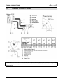
HDDE009/012/018/024
Indoor Units
Outdoor Units
AWSI-HDDE009-H11
AWSI-HDDE012-H11
AWSI-HDDE018-H11
AWSI-HDDE024-H11
AWAU-YDDE009-H11
AWAU-YDDE012-H11
AWAU-YDDE018-H11
AWAU-YDDE024-H11
REFRIGERANT
R410A
SM HDDE 1-A.1 GB
Version:1
HEAT PUMP
MAY-2013
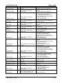
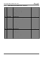
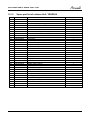
LIST OF EFFECTIVE PAGES
LIST OF EFFECTIVE PAGES
Note: Changes in the pages are indicated by a “Revision#” in the footer of each effected page
(when none indicates no changes in the relevant page). All pages in the following list represent
effected/ non effected pages divided by chapters.
Dates of issue for original and changed pages are:
Original ....... 01 ........ 22-May-2013
Total number of pages in this publication is 74 consisting of the following:
Page
No.
Revision
No. #
Page
No.
Revision
No. #
* Zero in this column indicates an original page.
SM HDDE 1-A.1 GB
A
Page
No.
Revision
No. #
TABLE OF CONTENTS
Table of Contents
1.
INTRODUCTION ............................................................................................................................. 1-1
2.
PRODUCT DATA SHEET............................................................................................................... 2-1
3.
RATING CONDITIONS ................................................................................................................... 3-1
4.
OUTLINE DIMENSION ................................................................................................................... 4-1
5.
PERFORMANCE DATA ................................................................................................................. 5-1
6.
PRESSURE CURVES..................................................................................................................... 6-1
7.
SOUND LEVEL CHARACTERISTICS ........................................................................................... 7-1
8.
ELECTRICAL DATA....................................................................................................................... 8-1
9.
WIRING DIAGRAM ......................................................................................................................... 9-1
10.
REFRIGERATION DIAGRAMS ...................................................................................................... 10-1
11.
TUBING CONNECTIONS ............................................................................................................... 11-1
12.
CONTROL SYSTEM ....................................................................................................................... 12-1
13.
TROUBLESHOOTING .................................................................................................................... 13-1
14.
CHARACTERISTICS OF SENSOR................................................................................................ 14-1
15.
EXPLODED VIEW & SPARE PART LIST...................................................................................... 15-1
16.
SERVICING..................................................................................................................................... 16-1
SM HDDE 1-A.1 G
i
INTRODUCTION
1.
INTRODUCTION
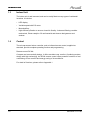
1.1
General
HDDE series is a mono-split DCI inverter air conditioner. This high-wall mounted
type indoor are mainly designed for residential buildings.
The ODU YDDE product is a DC inverter outdoor with high technology. By using
DC compressor sine wave torque control technology, this product provides more
comfort and economical operating.
The whole series includes 4 models 09/12/18/24 in cooling capacity.
1.2
Main Features
The unit benefits from the most advanced technological innovations, namely:
• DC inverter technology.
• R410A models
• Microprocessor control and indoor LED display
• High SEER/SCOP , A/A level with Average climate.
• Torque control for compressor running in lower Frequency but with low vibration
and little sound.
• Max allowing tubing distance of 25m(Model HDDE024).
• Up to 10 m vertical high between indoor and outdoor units
• Cooling operation at outdoor temperature up to 46ºC.
• Heating operation at outdoor temperature down to -15ºC.
• Easy installation and service.
• Sleep mode from remote control to save energy
• ON/OFF timer and clock display
• Vertical auto swing with motorized flap (any position stop)
• Intelligent Deicing
• Memory from power failure
• Rapid cooling/heating
• I-Feel function
• Cold air prevention in heating
• Clean function (Blow dry)
• Self diagnostic (Error indications) for ease of maintenance
1-1
SM HDDE 1-A.1 GB
INTRODUCTION
1.3
Indoor Unit
The indoor unit is wall mounted, and can be easily fitted to many types of residential
locations. It includes:
• LED display
• Variable speed with PG motor
• Motorized flap
• High efficiency filtration to ensure a best Air Quality : Advanced filtering combine
mechanical, Photo-catalytic + Bi-anti bacterial and observe bad gaseous and
smokes.
1.4
Control
The microprocessor indoor controller, and an infrared remote control, supplied as
standard, provide complete operating function and programming.
Remote control RC 8A:
Compact and economically design, it offers excellent user comfort. Combining modern
design with high technology, the RC8A remote control offers powerful functions of real
considering of user comfort and energy saving of air-conditioner.
For detail of functions, please refer to Appendix 1
1-2
SM HDDE 1-A.1 GB
INTRODUCTION
1.5
Outdoor Unit
The outdoor units can be installed as floor or wall mounted units by using a wall
supporting bracket. The metal sheets are protected by anti- corrosion paintwork
allowing long life resistance. All outdoor units are pre-charged. For further information
please refer to the Product Data Sheet, Chapter 2.
It includes:
• Compressor mounted in a soundproofed compartment :
• Axial fan.
• Outdoor coil with hydrophilic louver fins for RC units.
• Outlet air fan grill.
• Interconnecting wiring terminal block.
1.6
Tubing Connections
Flare type interconnecting tubing to be produced on site.
For further details please refer to the Installation Manual.
1.7
Inbox Documentation
Each unit is supplied with its own installation, operation and remote control manuals.
1-3
SM HDDE 1-A.1 GB
INTRODUCTION
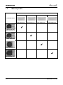
1.8
Matching Table
INDOOR UNITS
OUTDOOR UNITS
AWSI-HDDE009-H11
AWSI-HDDE012-H11
AWSI-HDDE018-H11
AWSI-HDDE024-H11
AWAU-YDDE009-H11
AWAU-YDDE012-H11
AWAU-YDDE018-H11
AWAU-YDDE024-H11
1-4
SM HDDE 1-A.1 GB
RATING CONDITIONS
2.
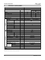
PRODUCT DATA SHEET
Model Indoor Unit
Model Outdoor Unit
Installation Method of Pipe
Characteristics
(1)
OUTDOOR
INDOOR
Capacity
Pdesign
SEER / SCOP (2)
Energy efficiency class
Annual energy consumption
Tbiv
Tol
Power supply
Circuit breaker rating
Fan type & quantity
Fan speeds
H/M/L
Air flow (3)
H/M/L
External static
Min-Max
pressure
(4)
Sound power level
H/M/L
Sound pressure level (5)
H/M/L
Moisture removal
Condensate drain tube I.D
Dimensions
WxHxD
Weight
Package dimensions
WxHxD
Packaged weight
Units per pallet
Stacking height
Refrigerant control
Compressor type, model
Fan type & quantity
Fan speeds
H/L
Air flow
H/L
Sound power level(4)
H/L
Sound pressure level(5)
H/L
Dimensions
WxHxD
Weight
Package dimensions
WxHxD
Packaged weight
Units per pallet
Stacking height
Refrigerant type
Refrigerant charge (standard connecting
tubing length)
Additional charge per 1 meter
Liquid line
Suction line
Connections
between units
Max.tubing length
Max.height difference
Operation control type
Heating elements
Others
Units
kW
kW
W/W
kWh
o
C
o
C
V/Ph/Hz
A
RPM
m3/hr
AWAU-HDDE009-N11
AWAU-YDDE009-H11
Flared
Heating
Cooling
Average
Warmer
2,6 (0,45-3,23)
3,0 (0,45-4,1)
2,6
2,6
2,8
5,6
3,8
4,4
A+
A
A+
163
958
891
N/A
-7
??
N/A
-15
-10
220-240V/Single/50Hz
16
Cross flow fan x1
1350/1100/900/700
1350/1140/980/820
600/520/370/280
600/520/370/280
Pa
0
dB(A)
dB(A)
l/hr
mm
mm
kg
mm
kg
units
units
55/48/40/34
43/38/30/24
0,8
16
770x283x201
8
855x280x360
11
21 units per pallet
7 levels
EEV
Rotary DC Inverter
Axial x 1
850
1800
62
51
776x540x320
36
851x595 x363
41
9 units per pallet
3 levels
R410A
RPM
m3/hr
dB(A)
dB(A)
mm
kg
mm
kg
Units
units
kg(5m)
0.8
gr / 1m
In.(mm)
In.(mm)
m.
m.
5m<L<15m 20g/m
1/4"(6.35)
3/8"(9.53)
Max.15
Max.10
Remote control
kW
(1) Rating conditions in accordance with ISO 5151 and ISO 13253 (for ducted units).
(2) SEER / SCOP calculation accordance with EN14825.
2-1
SM HDDE 1-A.1 GB
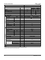
PRODUCT DATA SHEET
Model Indoor Unit
Model Outdoor Unit
Installation Method of Pipe
Characteristics
(1)
OUTDOOR
INDOOR
Capacity
Pdesign
SEER / SCOP (2)
Energy efficiency class
Annual energy consumption
Tbiv
Tol
Power supply
Circuit breaker rating
Fan type & quantity
Fan speeds
H/M/L
Air flow (3)
H/M/L
External static
Min-Max
pressure
Sound power level (4)
H/M/L
Sound pressure level (5)
H/M/L
Moisture removal
Condensate drain tube I.D
Dimensions
WxHxD
Weight
Package dimensions
WxHxD
Packaged weight
Units per pallet
Stacking height
Refrigerant control
Compressor type, model
Fan type & quantity
Fan speeds
H/L
Air flow
H/L
Sound power level(4)
H/L
Sound pressure level(5)
H/L
Dimensions
WxHxD
Weight
Package dimensions
WxHxD
Packaged weight
Units per pallet
Stacking height
Refrigerant type
Refrigerant charge (standard connecting
tubing length)
Additional charge per 1 meter
Liquid line
Suction line
Connections
between units
Max.tubing length
Max.height difference
Operation control type
Heating elements
Others
Units
kW
kW
W/W
kWh
o
C
o
C
V/Ph/Hz
A
RPM
m3/hr
AWAU-HDDE012-N11
AWAU-YDDE012-H11
Flared
Heating
Cooling
Average
Warmer
3,5 (0,6-3,96)
3,8 (0,6-5,13)
3,5
2,7
3,5
5,1
3,8
4,2
A
A
A+
240
995
1149
N/A
-7
??
N/A
-15
-10
220-240V/Single/50Hz
16
Cross flow fan x1
1350/1150/950/750
1350/1190/1020/850
680/560/410/300
680/560/410/300
Pa
0
dB(A)
dB(A)
l/hr
mm
mm
kg
mm
kg
units
units
56/49/41/35
44/39/31/25
1,4
16
770x283x201
9
855x280x360
12
21 units per pallet
7 levels
EEV
Rotary DC Inverter
Axial x 1
900
1800
62
53
848x540x320
40
881x595 x363
45
9 units per pallet
3 levels
R410A
RPM
m3/hr
dB(A)
dB(A)
mm
kg
mm
kg
Units
units
kg(5m)
1.0
gr / 1m
In.(mm)
In.(mm)
m.
m.
5m<L<20m 20g/m
1/4"(6.35)
3/8"(9.53)
Max.20
Max.10
Remote control
kW
(1) Rating conditions in accordance with ISO 5151 and ISO 13253 (for ducted units).
(2) SEER / SCOP calculation accordance with EN14825.
2-2
SM HDDE 1-A.1 GB
RATING CONDITIONS
Model Indoor Unit
Model Outdoor Unit
Installation Method of Pipe
Characteristics
Units
(1)
OUTDOOR
INDOOR
Capacity
Pdesign
SEER / SCOP (2)
Energy efficiency class
Annual energy consumption
Tbiv
Tol
Power supply
Circuit breaker rating
Fan type & quantity
Fan speeds
Air flow (3)
External static
pressure
Sound power level (4)
Sound pressure level (5)
Moisture removal
Condensate drain tube I.D
Dimensions
Weight
Package dimensions
Packaged weight
Units per pallet
Stacking height
Refrigerant control
Compressor type, model
Fan type & quantity
Fan speeds
Air flow
Sound power level(4)
Sound pressure level(5)
Dimensions
Weight
Package dimensions
Packaged weight
Units per pallet
Stacking height
Refrigerant type
kW
kW
W/W
kWh
o
C
o
C
V/Ph/Hz
A
H/M/L
H/M/L
RPM
m3/hr
AWAU-HDDE018-N11
AWAU-YDDE018-H11
Flared
Heating
Cooling
Average
Warmer
5,3 (1,2-6,3)
5,6 (1,1-6,4)
5,3
4,8
5,3
5,4
3,8
4,6
A
A
A++
345
1768
1611
N/A
-7
??
N/A
-15
-10
220-240V/Single/50Hz
25
Cross flow fan x1
1350/1100/950/800
1400/1200/1050/900
800/680/560/460
800/680/560/460
Min-Max
Pa
0
H/M/L
H/M/L
dB(A)
dB(A)
l/hr
mm
mm
kg
mm
kg
units
units
60/55/51/46
WxHxD
WxHxD
H/L
H/L
H/L
H/L
WxHxD
WxHxD
Refrigerant charge (standard connecting
tubing length)
Additional charge per 1 meter
Liquid line
Suction line
Connections
between units
Max.tubing length
Max.height difference
Operation control type
Heating elements
Others
RPM
m3/hr
dB(A)
dB(A)
mm
kg
mm
kg
Units
units
49/44/40/35
1,8
16
865x305x215
12
948x310x383
15
18 units per pallet
6 levels
Capillary
Twin Rotary DC Inverter
Axial x 1
750
3200
65
55
955x700x396
46
1029x750x458
50
6 units per pallet
2 levels
R410A
kg(5m)
1.3
gr / 1m
In.(mm)
In.(mm)
m.
m.
5m<L<25m 20g/m
1/4"(6.35)
1/2"(12.7)
Max.25
Max.10
Remote control
kW
(1) Rating conditions in accordance with ISO 5151 and ISO 13253 (for ducted units).
(2) SEER / SCOP calculation accordance with EN14825.
2-3
SM HDDE 1-A.1 GB
PRODUCT DATA SHEET
Model Indoor Unit
Model Outdoor Unit
Installation Method of Pipe
Characteristics
(1)
OUTDOOR
INDOOR
Capacity
Pdesign
SEER / SCOP (2)
Energy efficiency class
Annual energy consumption
Tbiv
Tol
Power supply
Circuit breaker rating
Fan type & quantity
Fan speeds
H/M/L
Air flow (3)
H/M/L
External static
Min-Max
pressure
(4)
Sound power level
H/M/L
Sound pressure level (5)
H/M/L
Moisture removal
Condensate drain tube I.D
Dimensions
WxHxD
Weight
Package dimensions
WxHxD
Packaged weight
Units per pallet
Stacking height
Refrigerant control
Compressor type, model
Fan type & quantity
Fan speeds
H/L
Air flow
H/L
Sound power level(4)
H/L
Sound pressure level(5)
H/L
Dimensions
WxHxD
Weight
Package dimensions
WxHxD
Packaged weight
Units per pallet
Stacking height
Refrigerant type
Refrigerant charge (standard connecting
tubing length)
Additional charge per 1 meter
Liquid line
Suction line
Connections
between units
Max.tubing length
Max.height difference
Operation control type
Heating elements
Others
Units
kW
kW
W/W
kWh
o
C
o
C
V/Ph/Hz
A
RPM
m3/hr
AWAU-HDDE024-N11
AWAU-YDDE024-H11
Flared
Heating
Cooling
Average
Warmer
6,45 (2,53-6,55)
7,0 (2,53-7,6)
6,45
5,8
6,2
5,4
3,8
4,6
A
A
A++
439
2137
1852
N/A
-7
??
N/A
-15
-10
220-240V/Single/50Hz
25
Cross flow fan x1
1350/1150/950/850
1400/1200/1000/900
1000/800/700/550
1000/800/700/550
Pa
0
dB(A)
dB(A)
l/hr
mm
mm
kg
mm
kg
units
units
63/57/52/49
51/47/42/39
2
16
1008X319X221
14,5
1076X328 X398
17,5
18 units per pallet
6 levels
Capillary
Twin Rotary DC Inverter
Axial x 1
RPM
m3/hr
dB(A)
dB(A)
mm
kg
mm
kg
Units
units
4000
68
58
980X790X427
55,5
1083X488X855
60,5
6 units per pallet
2 levels
R410A
kg(5m)
1.8
gr / 1m
In.(mm)
In.(mm)
m.
m.
5m<L<25m 50g/m
1/4"(6.35)
5/8"(15.88)
Max.25
Max.10
Remote control
kW
(1) Rating conditions in accordance with ISO 5151 and ISO 13253 (for ducted units).
(2) SEER / SCOP calculation accordance with EN14825.
2-4
SM HDDE 1-A.1 GB
RATING CONDITIONS
3. RATING CONDITIONS
Rating conditions in accordance with ISO 5151 and ISO 13253 (for ducted units).
Cooling:
Indoor:
27oC DB 19oC WB
Outdoor: 35 oC DB
Heating:
Indoor:
20oC DB
Outdoor: 7oC DB 6oC WB
3.1
Operating Limits
R410A
Indoor
Cooling
Heating
o
Upper limit
32 C DB 23 C WB
Lower limit
21oC DB 15oC WB
Upper limit
Lower limit
27oC DB
10oC DB
Voltage
3-1
o
Outdoor
46oC DB
10oC DB (HDDE009/012)
5oC DB (HDDE018/024)
24oC DB 18oC WB
-15oC DB -16oC WB
1-PH 50Hz 198 – 264 V
SM HDDE 1-A.1 GB
OUTLINE DIMENSION
4.
OUTLINE DIMENSION
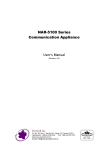
4.1
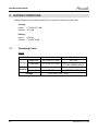
Indoor: HDDE009, HDDE012, HDDE018, HDDE024
Models
HDDE009/012
HDDE018
HDDE024
4-1
W
770
867
1008
H
283
305
319
D
201
215
221
SM HDDE 1-A.1 GB
OUTLINE DIMENSION
4.2
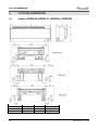
Outdoor: YDDE009
4.3
Outdoor: YDDE012
SM HDDE 1-A.1 GB
4-2
SOUND LEVEL CHARACTERISTICS
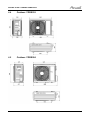
4.4
Outdoor: YDDE018
4.5
Outdoor: YDDE024
4-3
SM HDDE 1-A.1 GB
PERFORMANCE DATA
5.
PERFORMANCE DATA
SM HDDE 1-A.1 GB
5 -1
SOUND LEVEL CHARACTERISTICS
6.
PRESSURE CURVES
SM HDDE 1-A.1 GB
6-1
SOUND LEVEL CHARACTERISTICS
7.
SOUND LEVEL CHARACTERISTICS
7.1
Sound Pressure Level
SM HDDE 1-A.1 GB
7 -1
SOUND LEVEL CHARACTERISTICS
7.2
Sound Pressure Level Spectrum (Measured as Figure 1)
HDDE 1-A.1 GB
7-2
ELECTRICAL DATA
8.
ELECTRICAL DATA
MODEL
YDDE009
YDDE012
YDDE018
YDDE024
To indoor
Power Supply
1PH-220-240V-50Hz
7.3A
11.8A
Max Current, A
6.9A
12.4A
Circuit Breaker,A
16A
16A
25A
25A
Power Supply Wiring No. X Cross Section
mm2
3x1.5 mm2
3x1.5 mm2
3x2.5 mm2
3x2.5 mm2
Interconnecting Cable Model No. X Cross
Section mm2
4x1.5 mm2
4x1.5 mm2
4x2.5 mm2
4x2.5 mm2
NOTE
Power wiring cord should comply with local laws and electrical regulations requirements.
SM HDDE 1-A.1 GB
8-1
WIRING DIAGRAM
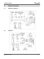
9.
WIRING DIAGRAM
9.1
HDDE009, HDDE012
9.2
HDDE018
SM HDDE 1-A.1 GB
9-1
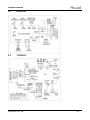
WIRING DIAGRAM
9.3
HDDE024
9.4
YDDE009
SM HDDE 1-A.1 GB
9-2
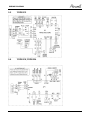
WIRING DIAGRAM
9.5
YDDE012
9.6
YDDE018,YDDE024
9-3
SM HDDE 1-A.1 GB
REFIGERATION DIAGRAMS
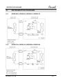
10.
REFRIGERATION DIAGRAMS
10.1
HDDE009+YDDE009, HDDE012+YDDE012
10.2
HDDE018+YDDE018, HDDE024+YDDE024
SM HDDE 1-A.1 GB
10-1
TUBING CONNECTIONS
11.
TUBING CONNECTIONS
When the outdoor unit is installed above the indoor unit an oil trap is required every 5m along the
suction line at the lowest point of the riser. In case the indoor unit is installed above the outdoor, no
trap is require
SM HDDE 1-A.1 GB
11-1
CONTROL SYSTEMS
12.
CONTROL SYSTEM
12.1
Electronic Control
12.1.1
Abbreviations
Abbreviation
A/C
BMS
PWR
CTT
DCI
EEV
HE
HMI
HST
Hz
ICT
IDU
MCU
OAT
OCT
ODU
OFAN
PFC
RAC
RAT
RC
RCT
RGT
RPS
RV
SB,STBY
SUCT
S/W
TBD
TMR
12.1.2
Definition
Air Condition
Building Management System
System Power
Compressor Top Temperature sensor
DC Inverter
Electronic Expansion Valve
Heating Element
Human Machine Interface
Heat Sink Temperature sensor
Hertz (1/sec) – electrical frequency
Indoor Coil Temperature (RT2) sensor
Indoor Unit
Micro Controller Unit
Outdoor Air Temperature sensor
ODU Coil Temperature sensor
Outdoor Unit
Outdoor Fan
Power Factor Corrector
Residential A/C
Room Air Temperature sensor
Reverse Cycle (Heat Pump)
Remote Control Temperature sensor
Return Gas Temperature sensor
Rounds per second (mechanical speed)
Reverse Valve
Stand By
Compressor Suction Temperature sensor
Software
To Be Defined
Timer
System Operation Concept
The control function is divided between indoor and outdoor unit controllers. Outdoor unit is the system
‘Master’, requesting the indoor unit for cooling/heating capacity supply. The indoor unit is the system
‘Slave’ and it must supply the required capacity unless it enters into a protection mode avoiding it from
supplying the requested capacity.
Target frequency is transferred via indoor to outdoor communication, and the calculation is based on
room temperature and set point temperature.
SM HDDE 1-A.1 GB
12-1
CONTROL SYSTEMS
12.1.3
Compressor Frequency Control
The Compressor Frequency Control is based on the PI scheme.
When starting the compressor, or when conditions are varied due to the change of the room
condition, the frequency must be initialized according to the ΔD value of the indoor unit and the Q
value of the indoor unit.
Q value: Indoor unit output determined from indoor unit capacity, air flow rate and other factors.
1. P control
Calculate ΔD value in each sampling time (20 seconds), and adjust the frequency according to its
difference from the frequency previously calculated.
2. I control
If the operating frequency is not change more than a certain fixed time, adjust the frequency up and
down according to the ΔD value.
Obtaining the fixed ΔD value
When the ΔD value is small- decrease the frequency
When the ΔD value is large- increase the frequency
3. Frequency management when other controls are functioning
When frequency is drooping;
Frequency management is carried out only when the frequency droops.
For limiting lower limit
Frequency management is carried out only when the frequency rises.
4. Maximum and minimum limits of frequency by PI control
The frequency upper and lower limits are set depending on indoor unit.
When low noise commands come from the indoor unit or when outdoor unit low noise or quiet
commands come from indoor unit, the upper limit frequency must be lowered than the usual setting.
(see 12.1.3.1)
12.1.3.1 Frequancy range
The compressor frequency limitation is set by the following table
Minimum Frequency(MinFreq)
Mode
Cooling
Heating
09
12
18
TBC
TBC
TBC
TBC
TBC
TBC
24
TBC
TBC
Maximum Frequency(MaxFreq)
24
09
12
18
TBC
TBC
TBC
TBC
TBC
TBC
TBC
TBC
12.1.5.1 Frequency Changes Control
Frequency change rate is 1 Hz/sec.
12-2
CONTROL SYSTEMS
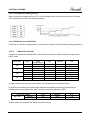
12.1.5.2 Compressor Starting Control
When turning the compressor from OFF to ON, the upper limit of frequency must be set as follows.
(The function must not be used when defrosting.)
12.1.5.3 Minimum On and Off Time
Prohibit to turn ON the compressor for 3 minutes after turning it off.(except during deicing protection)
12.1.6
Indoor Fan Control
8 Indoor fan speeds are determined for each model. 4 speeds for COOL modes and 4 speeds for
HEAT mode.
Unit Model
09
12
18
24
Mode
Cooling
Heating
Cooling
Heating
Cooling
Heating
Cooling
Heating
Turbo
(Super high)
1350
1350
1350
1350
1350
1400
1350
1450
High
Medium
Low
1100
1140
1150
1190
1100
1200
1150
1200
900
980
950
1020
950
1050
950
1000
700
820
750
850
800
900
850
900
In high/ medium/ low indoor fan user setting, unit will operate fan in selected speed.
In AutoFan user setting, fan speed will be adjusted automatically according to the difference
between actual room temperature (RAT) and user set point temperature (SPT).
Indoor Fan speed
Cooling
RAT-SPT
Heating
High
>=2
<=1
Medium
(0,2)
(1,3)
Low
<=0
>=3
In DRY mode, the automatic fan speed is forced to be low.
SM HDDE 1-A.1 GB
12-3
CONTROL SYSTEMS
12.1.6.1 Turbo Speed
In COOL and HEAT mode (not available in AUTO, DRY, FAN mode), press the Turbo button, the
super high fan speed is selected on Remote control and the indoor fan rotates at super high speed.
12.1.7
Outdoor Fan Control
12.1.7.1 FAN Speed Type
The outdoor fan motor is a one speed AC motor and controlled by the relay on outdoor controller.
12.1.7.2General rules
1. The outdoor fan is ON when compressor ON during cooling, dring and heating mode.
2. Outdoor fan OFF will delay 30sec when compressor is OFF during cooling and heating mode.
3. Outdoor fan control under outdoor deicing please refer to 12.11.6
12.1.8
Refrigerant control
12.1.8.1 EEV was used in model 09 and 12
1. EEV operation after power-on: When power on, EEV will open 240 steps and then move back
with 540steps. This position will be recognized as 0. Then EEV will open to 480 steps and be
ready for system operating.
2. EEV open loop: depends on OAT,RAT,SPT and compressor frequency after compressor starts
to operate.
3. Target CTT control: will be performed after compressor operates for 5min.The EEV opening will
be updated every 5s.
12.1.8.2 Capiliary is used in model 18 and 24
12.1.9
Reversing Valve (RV) Control
Reversing valve is on in heat mode.
Switching of RV state is done only after compressor is off for over 2 minutes.
12.2
Fan Mode
In this mode, the indoor fan may run at high,medium,low and automatic speed. The compressor,
outdoor fan and 4-way valve will be OFF.
In this mode, the range of setting temperature is 16~30 oC
12.3
Cool Mode
For model 09 and 12
If RAT≥SPT, the unit starts cooling operation. In this case, the compressor and outdoor fan will
operate and the indoor fan will run at the setting speed.
If RAT≤SPT-2, the compressor will stop operation and the outdoor fan will delay 30 seconds to stop.
While the indoor fan will run at the setting speed.
SM HDDE 1-A.1 GB
12-4
CONTROL SYSTEMS
If SPT-2<RAT<SPT, the unit will maintain the previous status.
For model 18 and 24
If RAT≥SPT-0.5, the unit starts cooling operation. In this case, the compressor and outdoor fan will
operate and the indoor fan will run at the setting speed.
If RAT≤SPT-2, the compressor will stop operation and the outdoor fan will delay 30 seconds to stop.
While the indoor fan will run at the setting speed.
If SPT-2<RAT≤SPT, the unit will maintain the previous status.
12.3.1
Indoor Fan operation under Cool Mode
When SPT-RAT<0, if indoor fan motor operates at high speed, the fan motor will operate at medium
speed. The medium speed or low speed will be maintained; (this condition should be executed
when compressor starts up); this function will be excluded in the super high speed; When (RATSPT) ≥1 , the fan will return to the setting fan speed.
In AutoFan user setting, fan speed will be adjusted automatically according to the SPT and RAT,
rerfer to 12.1.6
12.4
Heat Mode
For Model 09 and 12
If RAT≤SPT+2, the unit will operate in heating mode. The compressor, outdoor fan and 4-way valve
will operate and the indoor fan will delay 3min to start at the latest
If SPT+2≤RAT≤SPT+5,the unit will maintain the previous status.
If RAT≥SPT+5, the compressor will stop, the outdoor fan will delay 30s to stop and the indoor fan
will blow for 60s at the setting speed. During this period, the fan speed can’t be switched.
SM HDDE 1-A.1 GB
12-5
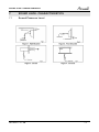
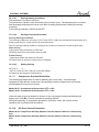
CONTROL SYSTEMS
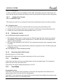
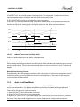
For model 18 and 24
If RAT≤SPT+3.5, the unit will operate in heating mode. The compressor, outdoor fan and 4-way
valve will operate and the indoor fan will delay 3min to start at the latest
If SPT+3≤RAT≤SPT+5,the unit will maintain the previous status.
If RAT≥SPT+5, the compressor will stop, the outdoor fan will delay 30s to stop and the indoor fan
will blow for 60s at the setting speed. During this period, the fan speed can’t be switched.
RAT
SPT+5
SPT+3
>=6min
COMP
ON
OFAN
ON
>=3min
OFF
30s
OFF
>=6min
ON
OFF
ON
30s
OFF
Anti-cold function
Max 3 min
IFAN
RV
12.4.1
Set Speed
60s
Set Speed
60s
ON
Indoor Fan Control in Heat Mode
Indoor fan speed depends on the indoor coil temperature
Anti-cold air function
When starting the heating mode, anti-cold air function will be activated and indoor fan can run at low
speed or stop running. This function will terminate after the unit runs for 3min or the ICT reaches 42
degree.
Residual heat blowing function
During heating, when the stopping condition for the compressor is reached, the compressor and the
outdoor fan motor stop running while the louver moves to position L. The indoor fan will stop after
running for 60s at setting speed.
12.5
Auto Cool/Heat Mode
In AUTO mode, the system selects the running mode (COOL/HEAT/FAN) automatically according
to the room temperature. The display shows the actual running mode and setting temperature.
There will be 30s delay for mode conversion.
1. When RAT≥25 oC, the cooling mode is selected.
2. When RAT≤22 oC, the unit runs in heating mode
3. When 22 oC <RAT< 25 oC, upon initial startup, the unit will enter auto mode and run in automatic
fan mode. If the other mode changes into auto mode, the previous running mode will remain.
SM HDDE 1-A.1 GB
12-6
CONTROL SYSTEMS
12.6
Dry Mode
If RAT>SPT, the unit starts drying operation. Indoor fan, outdoor fan and compressor will operate and
the indoor fan will run at low speed.
If SPT-2≤RAT≤SPT, the unit will keep running in the original mode.
If RAT<SPT-2, the compressor will stop running and the outdoor fan will delay 30 seconds to stop.
While the indoor fan will run at low speed.
In this mode, the Reverse Valve will be OFF and the temperature setting range is 16~30.
12.7
Louver Control
After power on, the up and down swing louver will automatically open and
then close completely.
In heating mode, if the swing function is not set, the up and down louver
will rotate to maximum in clockwise direction. Then it will rotate to position
D. Under other states, the upper and lower air deflector will rotate to level
L.
If the swing function is set when starting the unit, the louver will swing
between Position L and D. there are 7 states for louver: in position L, A, B,
C, D, and swing between L and D, stop in any place between Position L
and position D. When the unit is turned off, the air deflector will stay in
position 0.
The swing is available only when the swing function is set and the indoor fan is running.
The louver swing can also be set between L and B, between A and C, between B and D.
SM HDDE 1-A.1 GB
12-7
CONTROL SYSTEMS
Under clean function, the indoor fan will continue operation for 2 min at low speed after the
unit is turned OFF.
Clean function is defaulted as OFF after unit is
Power ON. Clean function is not available in Auto,
Fan or Heat mode.
12.9
Sleep function
Pressing SLEEP b vutton will enable the Sleep function.
will be shown on remote control.
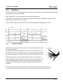
Sleep function in Cool and Dry mode:
The SPT will be adjusted according to following chart.
Sleep function in Heat mode:
The SPT will be adjusted according to following chart.
Press either Sleep button or ON/OFF button can cancel the Sleep function.
Sleep function will not be available in Auto mode or Fan mode.
12.10
I-Feel function
I-Feel function maintains the room temperature by comparing the RCT on remote control.
Pressing IFEEL button will enable the I-Feel function.
Will be shown on remote control.
Under I-Feel function, remote control sends I-Feel data every 10 min to IDU controller. If the IDU
controller does not received I-Feel data after 11 min. I-Feel function will be interrupted and then the
AC will work according to RAT on the IDU. I-Feel function cannot be remembered after power failure.
SM HDDE 1-A.1 GB
12-8
CONTROL SYSTEMS
12.11
Protections
There are 4 protection codes.
Normal (Norm) – unit operate normally.
Stop Rise (SR) – compressor frequency can not be raised but does not have to be decreased.
HzDown – Compressor frequency is reduced by 2Hz/s
Stop Compressor (SC) – Compressor is stopped.
12.11.1
Indoor Coil Defrost Protection
Conditions for Start Controlling
Judge the controlling start with the ICT (Indoor Coil Temperature) after 2 sec from operation start.
During cooling operation, the signals being sent from the indoor unit allow the operating frequency
limitation and then prevent freezing of the indoor heat exchanger.
Compressor will stop when ICT <= -1 oC for continuous 3 mins.
If the unit stops as such protection for 6 times, it can not resume running automatically and display
error code E2, it can resume by pressing ON/OFF.
During the operating, If compressor operates for more than 10min, the counter of stop operation
due to protection will be cleared.
12.11.2
Compressor over Heating Protection
The Discharging temperature is used as the compressor’s internal temperature. If the discharge
temperature rises above a certain level, the operating frequency upper limit is set to keep this
temperature from going up further.
Model 09/12 : Compressor will stop when CTT >110C
Model 18/24 : Compressor will stop when CTT >115C
If the unit stops as such protection for 6 times, it can not resume running automatically and display
error Code E4, it can be resumed by pressing ON/OFF.
During the operating, If compressor operates for more than 10min, the counter of stop operation
due to protection will be cleared.
12.11.3
Indoor Coil over Heating Protection (Heat Mode)
Conditions for Start Controlling
Judge the controlling start with the ICT after 2 sec from operation start.
During heating operation, the signals being sent from the indoor unit allow the operating frequency
SM HDDE 1-A.1 GB
12-9
limitation and prevent abnormal high pressure.
CONTROL SYSTEMS
For Model 09/12: Compressor will stop when ICT reaches 62C
For Model 18/24, Compressor will stop when ICT reaches 64C
If the unit stops as such protection for 6 times, it can not resume running automatically and display
the error code E8, it can resume by pressing ON/OFF.
During the operating, If compressor operates for more than 10min, the counter of stop operation
due to protection will be cleared.
12.11.4
Outdoor Coil Overheating protection (Cool/Dry Mode):
During heating operation, the ODU Coil Overheating Protection is detected by temperature sensor
OCT.
For Model 09/12: Compressor will stop when OCT reaches 62C
For Model 18/24, Compressor will stop when OCT reaches 65C
If the unit stops as such protection for 6 times, it can not resume running automatically and display
the error code E8, it can resume by pressing ON/OFF.
During the operating, If compressor operates for more than 10min, the counter of stop operation
due to protection will be cleared.
12.11.5
Compressor over Current Protection
Detect an input current by the CT during the compressor is running, and set the frequency upper
limit from such input current. In case of heat pump model, this control is the upper limit control
function of the frequency which takes priority of the lower limit of four way valve activating
compensation.
Detail
Model 09/12: Compressor will stop when AC current reaches 14.0A for continuously 2.5s.
Model 18/24: Compressor will stop when AC current reaches 17.0A for continuously 2.5s.
If the unit stops as such protection for 6 times, it can not resume running automatically and display
error Code E5, it can resume by pressing ON/OFF.
During the operating, If compressor operates for more than 10min, the counter of stop operation
due to protection will be cleared.
12.11.6
Outdoor Coil Deicing Protection
This protection is for Heat Pump Only
This protection is carried out by the cooling cycle (reverse cycle). The defrosting time or outdoor
heat exchanger temperature must be more than its setting values when finishing the deicing
protection.
In the deicing protection, IFAN is forced OFF.
SM HDDE 1-A.1 GB
12-10
CONTROL SYSTEMS
12.11.6.1
Deicing Starting Conditions
This protection is for Heat Pump Only
This protection is carried out by the cooling cycle (reverse cycle). The defrosting time or outdoor
heat exchanger temperature must be more than its setting values when finishing the deicing
protection.
In the deicing protection, IFAN is forced OFF.
12.11.6.2
Deicing Protection Procedure
Deicing Starting Conditions:
The starting conditions is a function of OAT and (OCT). Under the conditions that the system is in
heating operation for certain period (Accumulated time)
After the deicing starting condition is detected for continuous 3minutes, the de-icing will start.
Start deicing:
Compressor stops and starts up 55S later
OFAN will stop after compressor stops for 50S
Finish Deicing:
Compressor stops and starts up 55S later;
OFAN will start up when the compressor is stopping
12.11.6.3
Exiting Deicing
OCT≤12°C
or
OAT<5°C and OCT≥6°C lasts for more than 80Sec
Or Maximum de-icing time reaches 8min
12.11.7
Compressor Overload Protection:
The Discharging temperature is used for detecting the comp’ temp’. If the discharge
temperature rises above a certain level, the operating frequency upper limit is set to keep
this temperature from going up further.
Model 09/12 : Compressor will stop when CTT >110C
Model 18/24 : Compressor will stop when CTT >115C
If the unit stops as such protection for 6 times, it can not resume running automatically and
display error Code E4, it can be resumed by pressing ON/OFF.
During the operating, If compressor operates for more than 10min, the counter of stop
operation due to protection will be cleared.
12.11.8
AC Over Current Protection:
Model 09/12: Compressor will stop when AC current reaches 14.0A for continuously
2.5s.
Model 18/24: Compressor will stop when AC current reaches 17.0A for continuously
2.5s.
SM HDDE 1-A.1 GB
12-11
CONTROL SYSTEMS
If the unit stops as such protection for 6 times, it can not resume running automatically and
display error Code E5, it can resume by pressing ON/OFF.
During the operating, If compressor operates for more than 10min, the counter of stop
operation due to protection will be cleared.
12.11.9
AC Voltage Drop:
During compressor operation, the system will stop in case of an AC voltage malfunction the
unit will resume its operation automatically after 3min.
12.11.10 Communication malfunction:
If the unit does not receive correct signal from indoor unit for 3min continuously, the unit will
stop and will show communication malfunction protection (E6);
if the communication malfunction had been resumed and the compressor had stopped for a
period of 3min, the unit will restart its operation.
12.11.11 Overload protection of compressor
The Over Load Protector (OLP) is equipped to have the protection by compressor shell
temperature.
If OLP is detected OPEN for 3s successively, the system will stop operation.
it OLP is detected CLOSE, and compressor has stopped for 3min, the AC can go back to
normal operation.
If the unit stops operation due to overload protection of compressor for 3 times successively,
the unit can’t resume operation automatically and will show H3 error code, except pressing
ON/OFF button.
* The counter can be cleared if compressor operates for 30min.
SM HDDE 1-A.1 GB
12-12
CONTROL SYSTEMS
12.11.12 IPM module protection
After compressor is turned on, Once IPM modular protection signal (by its current or
temperature )is detected, the unit will stop operation immediately.
If modular protection is resumed and compressor has stopped for 3min, the complete unit
can then be allowed to resume operation.
If the unit stops operation due to modular protection for 3 times successively, the unit can’t
resume operation automatically and show error code H5, except pressing ON/OFF button.
* If compressor has operates for more than 10 min successively, the counter will be cleared.
12.11.13 Modular overheating protection (HST overheating protection)
Protect the IPM modular by reducing compressor frequency or stop compressor according
to the Module temperature (HST)
When HST>=80C, compressor frequency will be decreased or stopped increasing.
When HST>=95C, the unit will stop. (Back to normal when HST>87C and Comp OFF
time >3mins.)
If the unit stops operation for 6 times, the unit can’t resume its operation and show error
code P8 . Only press ON/OFF button can resume the operation.
* If compressor has operates for more than 10 min successively, the counter will be cleared.
12.11.14 Sensor Failure
When the temperature sensor is detected short circuit or open circuit for 5s successively,
the unit will stop operation, and error code will be shown accordingly.
Error code of Sensor:
F1 – RAT Sensor Failure
F2 – ICT Sensor Failure
F3 – OAT Sensor Failure
F4 – OCT Sensor Failure
F5 – CTT Sensor Failure
ICT sensor failure will not be detected during ODU deicing stage. It starts detecting
the sensor failure after deicing is finished for 5 mins.
Other sensor failure will be detected at any other time.
SM HDDE 1-A.1 GB
12-13
CONTROL SYSTEMS
12.12
Operating the Unit from the ON/OFF Button
The ON/OFF button allows to operate the unit in AUTO mode, the microcomputer will monitor the
room temperature and select the (COOL, HEAT, FAN) mode automatically, and temperature/Fan
speed settings can not be changed.
12.13
Indoor Unit Controllers and Indicators
The following is schematic drawing for the display:
RUN INDICATOR
COOL INDICATOR
DRY INDICATOR
HEAT INDICATOR
2* 7 segments display
1.
Lights up when the Air Conditioner is connected to power
and the mode is STBY.
2. When the unit is turned on remotely, the RUN LED goes out
while the current setting running mode is displayed
1. Lights up during specified operation mode
(COOL/DRY/HEAT).
1.
2.
3.
Unit ON/OFF Button
SM HDDE 1-A.1 GB
In normal situation, the setting temperature is displayed.
Shows outdoor temperature or indoor temperature when
receiving the corresponding demand from controller. It resumes
displaying setting temperature 5s later
Shows the alarm code whenever there is an alarm.(Refer to
Diagonostic part)
Short pressing(Less than 5s) : Unit will swich between Auto mode
and STBY. System will select the COOL/HEAT/FAN mode
automatically and temperature/Fan speed settings can not be
changed.
Long pressing (5~10s): System will enter into Force cooling
operating
12-14
12.14
Test Mode
TO BE CONFIRMED
SM HDDE 1-A.1 GB
12-15
TROUBLESHOOTING
13.
TROUBLESHOOTING
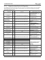
13.1
ELECTRICAL & CONTROL TROUBLESHOOTING
13.1.1
Precautions before Performing Inspection or Repair
Be cautious during installation and maintenance. Do operation following the regulations to avoid
electric shock and casualty or even death due to drop from high attitude.
* Static maintenance is the maintenance during de-energization of the air conditioner.
For static maintenance, make sure that the unit is de-energized and the plug is disconnected.
*Dynamic maintenance is the maintenance during energization of the unit. Before dynamic
maintenance, check the electricity and ensure that there is ground wire on the site. Check if there is
electricity on the housing and connection copper pipe of the air conditioner with voltage tester. After
ensure insulation place and the safety, the maintenance can be performed.
Take sufficient care to avoid directly touching any of the circuit parts without first turning off the power.
At time such as when the circuit board is to be replaced, place the circuit board assembly in a vertical
position. Normally, diagnose troubles according to the trouble diagnosis procedure as described
below.(Refer to the check points in servicing written on the wiring diagrams attached to the
indoor/outdoor units.)
Precautions when inspecting the control section of the outdoor unit: A largecapacity electrolytic capacitor is used in the outdoor unit controller (inverter).Therefore,if the
power supply is turned off, charge(charging voltage DC280V to
380V)remains and discharging takes a lot of time. After turning off the power source,if touching the
charging section before discharging, an electrical shock may be caused.
The outdoor unit can not be started up until the unit is de-energized for 20min
13.1.2
Confirmation
13.1.2.1 Confirmation of Power Supply Confirm that the power breaker operates(ON)
normally;
13.1.2.2 Confirmation of Power Voltage Confirm that power voltage is AC220~240V +/10%. If power voltage is not in this range, the unit may not operate normally.
SM HDDE 1-A.1 GB
13-1
TROUBLESHOOTING
13.1.3
Judgment by Indoor/Outdoor Unit Diagnostics
If the malfunction still exists 4min later after stop of unit due to compressor protection, error code will be
directly displayed though indoor display. In other situations, error code can be displayed by pressing
LIGHT button 6 times within 4s.
System High Pressure
Protection
2
x
7
Seg
men
ts
E1
OPER Indicator OFF 3s and blink once
Indoor Coil Defrost
Protection
E2
OPER Indicator OFF 3S and blink twice
Malfunction
System block or
refrigerant leakage
E3
Compressor over Heating
Protection
E4
IDU LEDs
OPER Indicator OFF 3S and blink 3 times
OPER Indicator OFF 3S and blink 4 times
OPER Indicator OFF 3S and blink 5 times
AC Over Current
Communication
Malfunction
Indoor/Outdoor Coil Over
Heating Protection
E5
OPER Indicator OFF 3 Sand blink 6 times
E6
OPER Indicator OFF 3S and blink 8 times
E8
EEPROM problem
Stop rise/HZ down due to
HST over heating
protection
EE
EU
Jumper Cap Malfunction
Gathering refrigerant
RAT Failure
ICT Failure
C5
F0
F1
F2
OAT Failure
F3
HEAT Indicator OFF 3Sand blink15
times
OPER Indicator OFF 3S and blink 15 times
F4
CTT Failure
F5
HZ down due to overload
F6
COOL Indicator OFF 3S and blink 5
times
COOL Indicator OFF 3S and blink for 6 times
Hz down due to over
current
F8
Hz down due to CTT over
heating
F9
Stop rise/HZ down due to
IDU defrosting protection
FH
SM HDDE 1-A.1 GB
2. Fan speed is abnormal
3. Evaporator is dirty.
1.Low-pressure protection
2.Low-pressure protection of system
3.Low-pressure protection of
compressor
1. EEV connection problem or
damage
2. Refrigerant leakage
3. Supply
Poor heat
exchange
1.
voltage
is unstable
2. Supply voltage is too low and
load is too high
3. Evaporator is dirty.
1. Wiring mistakes
2. IDU or ODU PCB problem
1. Too high ambient temperature
2. Poor heat exchange (including
blockage and bad radiating
environment )
Outdoor main board damaged
1. Insufficient grease on heatsink or
poor connection of heatsink to PCB
2. Outdoor PCB problem.
1. No jumper cap insert on main
board.
2. Incorrect insert of jumper cap.
3. Jumper cap damaged.
4. Abnormal detecting circuit of
main board.
Normal
function
COOL Indicator OFF 3S and blink once
COOL Indicator OFF 3S and blink twice
COOL Indicator OFF 3Sand blink3 times
COOL Indicator OFF 3Sand blink4 times
OCT Failure
Possible causes / Actions
1. Refrigerant was superabundant
2. Poor heat exchange
(including filter blockage of heat
exchanger and bad
radiating environment)
3.Ambient
temperature
is too
1.
Poor air-return
in indoor
unithigh.
COOL Indicator OFF 3S and blink 8 times
COOL Indicator OFF 3S and blink 9 times
1. Sensor connection is not good
2. Indoor ambient temp. sensor
damaged.(check with sensor
resistance
value chart)
3.
Mainhigh
board
damaged.
1. Too
ambient
temperature
2. Poor heat exchange (including
blockage and bad radiating
environment
)
1.The
input supply
voltage is too low
2.System pressure is too
high and overload
1.Overload or temperature is too
high;
2.Refrigerant is insufficient
3.Malfunction of electric expansion
valve
1. Poor air-return in indoor unit
(EEV)
2. Fan speed is abnormal
3. Evaporator is dirty.
13-2
TROUBLESHOOTING
DC Over Voltage
PH
COOL Indicator OFF 3S and blink
11 times
DC Under Voltage
PL
HEAT Indicator OFF 3Sand
blink21 times
1. AC power supply is higher than 2
2. Outdoor PCB circuit malfunction
1. AC power supply voltage is less than
150VAC
2. Outdoor PCB circuit malfunction
P5
COOL Indicator OFF 3Sand
blink15 times
1. Abnormal power input voltage.
2. Compressor wiring mistake.
3. Liquid and gas valve are not open.
4. EEV damaged or not proper working
5. Poor heat exchange.
6. Over charged system.
Charging malfunction
of capacitor
PU
HEAT Indicator OFF 3Sand
blink17 times
HST Failure
P7
HEAT Indicator OFF 3Sand
blink18 times
HST over
heating
protection
P8
HEAT Indicator OFF 3Sand
blink19 times
1. Reactor open
2. Charging relay or other components
damaged on PCB.
1. Senor was broken or damaged
2. PCB temperature detection cuircuit has
problem
1. Insufficient attachment of IPM module
to Heatsink
2. Outdoor PCB problem.
H3
HEAT Indicator OFF 3Sand
blink3 times
1. EEV connection problem or damaged
2. Refrigeratn leakage
3. OLP damaged
DC Over Current
Compressor
overload protection
IPM protection
H5
HEAT Indicator OFF 3Sand
blink5 times
No feedback of
indoor motor
H6
OPER Indicator OFF 3S and blink
11 times
1.Abnormal power input voltage.
2.Compressor wiring mistake.
3.Liquid and gas valve are not open.
4.EEV damaged or not proper working
5.Poor heat exchage.
6.Over charged system.
1. Bad contact of DC motor feedback
terminal.
2. Bad contact of DC motor control end.
3. Fan motor is blocked.
4. Motor malfunction.
5. Malfunction of main board rev
detecting circuit.
HEAT Indicator OFF 3Sand
blink7 times
1. Abnormal power input voltage.
2. Compressor wiring mistake.
3. Liquid and gas valve are not open.
4. EEV damaged or not proper working
5. Poor heat exchage.
6. Over charged system.
Desynchronizing
of compressor
H7
PFC protection
Outdoor DC fan
motor malfunction
HC
Over Power Protection
L9
IDU/ODU Mismatch
LP
Start-up Failure
LC
ODU Deicing
SM HDDE 1-A.1 GB
L3
HEAT Indicator OFF 3Sand
blink6 times
OPER Indicator OFF 3S and blink
23 times
OPER Indicator OFF 3S and blink
20 times
OPER Indicator OFF 3S and
blink19 times
HEAT Indicator OFF 3Sand
blink11 times
HEAT Indicator OFF 3Sand
blink once(during blinking, ON
10s and HEAT Indicator OFF
0.5s)
1. PFC module assembly problem.
2. Poor heat exchange of Heatsink
3. PFC reactor problem.
4. Abnormal power voltage
5. PFC circuit problem on PCB
1.DC fan motor malfunction or blocked
2.Bad connection
To protect the electronical components when
detect high power
Indoor unit and outdoor unit doesn't
match
1. Compressor wiring mistake
2. Over charged system
3. System not balanced before
compressor starting
4. Compressor problem
Its the normal state
13-3
TROUBLESHOOTING
Malfunction of phase
current detection
circuit for compressor
Malfunction of
voltage dropping for
DC BUS
AC Current detection
problem
The RV is abnormal
Zero-crossing
protection
(IDU)
Outdoor unit zerocross detecting error
SM HDDE 1-A.1 GB
U1
HEAT Indicator OFF 3Sand blink13
times
Outdoor main board damaged
U3
HEAT Indicator OFF 3Sand blink20
times
Supply voltage is unstable
U5
COOL Indicator OFF 3Sand blink13
times
Outdoor main board damaged
U7
COOL Indicator OFF 3Sand blink20
times
1.Supply voltage is lower than AC175V;
2.Wiring terminal RV is loosened or
broken;
3.RV is damaged.
U8
OPER Indicator OFF 3S and blink 17
times
1.Power supply is abnormal
2.Detection circuit of indoor control main
board is abnormal.
U9
Outdoor main board damaged
13-4
TROUBLESHOOTING
13.1.4
Checking the refrigeration system
Checking system pressures and other thermodynamic measures should be done when system
is in Test Mode (in Test mode, system operates in fixed settings). The performance curves
given in this manual are given for unit performance in test mode when high indoor fan speed is
selected.
Entering test mode please refer to section 12- Control system.
13.2
Simple procedures for checking the Main Parts
13.2.1
Checking Mains Voltage.
Confirm that the Mains voltage is between 198 and 264 VAC. If Mains voltage is out of this
range, abnormal operation of the system is expected. If in range check the Power (Circuit)
Breaker and look for broken or loosed cable lugs or wiring mistake(s).
13.2.2
Checking Power Input.
If Indoor unit power LED is unlighted, power down the system and check the fuse of the Indoor
unit. If the fuse is OK replace the Indoor unit controller. If the fuse has blown, replace the fuse
and power up again.
Checking Power Input procedure for the Outdoor unit is the same as with the Indoor unit.
13.2.3
Checking the Outdoor Fan Motor.
For AC motor
Check the voltage between two pins Hi and N of connector OFAN on controller, normal
voltage is 220~240VAC.
For DC Motor
Check the voltage between any two pins of connector OFAN on controller, normal voltage is
280~380VDC
13.2.4
Checking the Compressor.
The compressor is brushless permanence magnetic DC motor. Three coil resistance is
same. Check the resistance between three poles. The normal value should be with the
almost same value. Pay attention U,V, W are respective to connect to
RED,YELLOW,BLUE wires.
13.2.5
Checking the Reverse Valve (RV).
Running in heating mode, check the voltage between two pins of reverse valve connector,
normal voltage is 220~240VAC.
SM HDDE 1-A.1 GB
13-5
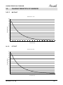
CHARACTERISTICS OF SENSOR
14.
CHARACTERISTICS OF SENSOR
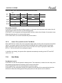
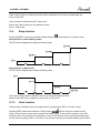
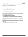
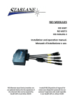
14.1.1
RAT/OAT
RAT/OAT R-T chart
140
130
120
110
Resistance(Kohm)
100
90
80
70
60
50
40
30
20
10
0
-20
-15
-10
-5
0
5
10
15
20
25
30
35
40
45
50
55
60
65
70
35
40
45
50
55
60
65
70
Temperature(C)
14.1.2
ICT/OCT
Resistance(Kohm)
ICT/OCT R-T Chart
180
170
160
150
140
130
120
110
100
90
80
70
60
50
40
30
20
10
0
-20
-15
-10
-5
0
5
10
15
20
25
30
Temperature(C)
SM HDDE 1-A.1 GB
14-1
CHARACTERISTICS OF SENSOR
14.1.3
CTT
CTT R-T Chart
14-2
SM HDDE 1-A.1 GB
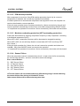
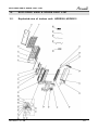
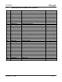
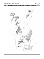
EXPLODED VIEW & SPARE PART LIST
15.
EXPLODED VIEW & SPARE PART LIST
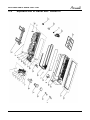
15.1
Exploded view of indoor unit: HDDE009, HDDE012
SM HDDE 1-A.1 GB
15-1
SERVICING
15.2
Spare part list of indoor Unit: HDDE009
NO.
1
2
3
4
5
Part Code
G1112208201
G20012806B
G24252019
G63062017
G2001237501
Part Description
Filter Sub-Assy
Front Panel
Screw Cover
Membrane
Front Case Assy
6
7
8
9
10
11
12
13
14
15
16
17
18
19
20
G10512119
G26112486
G10512160
G1054202001
G0523204101
G2220229501_K88497
G0125201801A
G15002020
G26112191
G10352423
G0100227003
none
G24212108
G76512210
G76712032
Guide Louver
Helicoid tongue
Air Louver
Shaft of Guide Louver
Drainage Pipe Sub-assy
Rear Case assy
Wall Mounting Frame
Motor Sub-Assy
Motor Press Plate
Cross Flow Fan
Evaporator Assy
Tube Sensor Bushing
Evaporator Support
Fan Bearing
Bearing Holder
1
1
2
2
1
1
1
1
1
1
1
1
1
1
1
21
22
23
24
25
26
27
28
29
30
31
32
33
34
35
36
37
G1054202101
G20402706
G20122106
G01592076
G73012005
G1521210701
G22242083
G22242084
G30568112
G20112086
G30148846
G42011233
G30510460_K88497
G390000453
G39000305
G400204643
none
Propeller Axile Bush
Electric Box Assy
Electric Box Cover
Shield Cover
Crank
Step Motor
Indicator shield cover
Indicator Light Cover
Display Board
Electric Box
Main Board
Terminal Board
Remote Controller
Ambient Temperature Sensor
Temperature Sensor
Power Cord
Pipe Connection Nut accessories
1
1
1
1
1
1
1
1
1
1
1
1
1
1
1
1
1
15-2
qty
2
1
1
1
1
SM HDDE 1-A.1 GB
SERVICING
15.3
NO.
1
2
3
4
5
6
7
8
9
10
11
12
13
14
15
16
17
18
19
20
21
22
23
24
25
26
27
28
29
30
31
32
33
34
35
36
37
Spare part list of indoor Unit: HDDE012
Part Code
G1112208201
G20012806B
G24252019
G63022016
G20012824
G10512119
G26112486
G10512160
G1054202001
G0523204101
G2220229501_K8849
G7
G0125201801A
G15002020
G26112191
G10352423
G0100274503
none
G24212108
G76512210
G76712032
G1054202101
G20402765
G20122106
G01592076
G73012005
G1521210701
G22242083
G22242084
G30568112
G20112086
G30148846
G42011233
G30510460_K88497
G390000453
G39000305
G400204643
none
SM HDDE 1-A.1 GB
Part Description
Filter Sub-Assy
Front Panel
Screw Cover
Membrane
Front Case Assy
Guide Louver
Helicoid tongue
Air Louver
Shaft of Guide Louver
Drainage Pipe Sub-assy
Rear Case assy
Wall Mounting Frame
Motor Sub-Assy
Motor Press Plate
Cross Flow Fan
Evaporator Assy
Tube Sensor Bushing
Evaporator Support
Fan Bearing
Bearing Holder
Propeller Axile Bush
Electric Box Assy
Electric Box Cover
Shield Cover
Crank
Step Motor
Indicator shield cover
Indicator Light Cover
Display Board
Electric Box
Main Board
Terminal Board
Remote Controller
Ambient Temperature Sensor
Temperature Sensor
Power Cord
Pipe Connection Nut accessories
qty
2
1
1
1
1
1
1
2
2
1
1
1
1
1
1
1
1
1
1
1
1
1
1
1
1
1
1
1
1
1
1
1
1
1
1
1
1
15-3
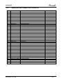
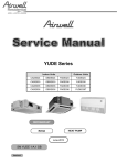
EXPLODED VIEW & SPARE PART LIST
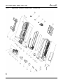
15.4
15-4
Exploded view of indoor unit: HDDE018
SM HDDE 1-A.1 GB
SERVICING
15.5
NO.
1
2
3
4
5
6
7
8
9
10
11
12
13
14
15
16
17
18
19
20
21
22
23
24
25
26
27
28
29
30
31
32
33
34
35
36
37
38
39
Spare part list of indoor Unit: HDDE018
Part Code
G4202300115
G22242083
G22242084
G30568112
G20112103
G4201026601
G01592087
G30148858
G20402748
G20122123
G01592088
G20122142
G4002046421
G40020538
G20012872_K8849
G7
G20012808P
G20012873
G242520041
G15012146
G10512140
G10542036
G01002320
G26112164
G10352036
G26112231
G15012086
G10582070
G26112232
G10512160
G0523001407
G22202154
G01252484
G76712012
G10512037
G26152022
G30510460_K8849
7
G7651205102
G24212119
G11122104
SM HDDE 1-A.1 GB
Part Description
Jumper
Indicator shield cover
Indicator Light Cover
Display Board
Electric Box
Terminal Board
Shield cover of Electric Box
Main Board
Electric Box Assy
Electric Box Cover
Shield Cover of Electric box Cover
Electric Box Cover2
Power Cord
Connecting Cable
Front Panel Assy
Front Panel
Front Case Assy
Screw Cover
Fan Motor
Guide Louver
Axile Bush
Evaporator Assy
Pipe Clamp
Cross Flow Fan
Motor Press Plate
Step Motor
Crank
Helicoid tongue
Air Louver
Drainage hose
Rear Case assy
Wall Mounting Frame
Water Tray Glue Plug
Left Axile Bush
Ring of Bearing
Remote Controller
O-Gasket sub-assy of Bearing
Evaporator Support
Filter Sub-Assy
qty
1
1
1
1
1
1
1
1
1
1
1
1
1
1
1
1
1
1
1
1
1
1
1
1
1
1
1
1
2
1
1
1
1
1
1
1
1
1
2
15-5
EXPLODED VIEW & SPARE PART LIST
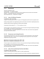
15.6
Exploded view of indoor unit: HDDE024
'
I'
I '
I
' ,i
I
I
I
I
I
I
I
I
I
I
(A.)
=
,..
ru
I ',
I
'
I
'
I
',
I
'
....0
I
',
I
'
I
)
I
I
I
I
I
I
I
I
I
I
I
I
I
I
I
I
I
I
I
I
I
I
I
I
I
I
I
I
I
I
I
I
I
I
I
I
I
I
I
I
I
I
I
{
'
I
'
15-6
I
I
I
I
'
;
I
I
I
I '>'v/
(
SM HDDE 1-A.1 GB
SERVICING
15.7
NO.
1
2
3
4
5
6
7
8
9
10
11
12
13
14
15
16
17
18
19
20
21
22
23
24
25
26
27
28
29
30
31
32
33
34
35
36
37
38
39
Spare part list of indoor Unit: HDDE024
Part Code
G4202300127
G22242083
G22242084
G30568112
G20112103
G42011233
G01592087
G30148859
G20402814
G20122123
G01592088
G20112081
G4002046418
G40020538
G20012828_K8849
G7
G20012809P
G20012845
G24252016
G15012098
G10512138
G10542036
G0100257205
G26112188
G10352030
G26112316
G1521300101
G10582070
G26112229
G10512139
G0523001405
G22202157
G01252032
G76712012
G10512037
G26152025
G30510460_K8849
G7
G7651205102
G24212103
G11122091
SM HDDE 1-A.1 GB
Part Description
Jumper
Indicator shield cover
Indicator Light Cover
Display Board
Electric Box
Terminal Board
Shield cover of Electric Box
Main Board
Electric Box Assy
Electric Box Cover
Shield Cover of Electric box Cover
Electric Box Cover2
Power Cord
Connecting Cable
Front Panel Assy
Front Panel
Front Case Assy
Screw Cover
Fan Motor
Guide Louver
Axile Bush
Evaporator Assy
Pipe Clamp
Cross Flow Fan
Motor Press Plate
Stepping Motor
Crank
Helicoid tongue
Air Louver
Drainage hose
Rear Case assy
Wall Mounting Frame
Water Tray Glue Plug
Left Axile Bush
Ring of Bearing
Remote Controller
O-Gasket sub-assy of Bearing
Evaporator Support
Filter Sub-Assy
qty
1
1
1
1
1
1
1
1
1
1
1
1
1
1
1
1
1
3
1
1
2
1
1
1
1
1
1
1
3
1
1
1
1
1
1
1
1
1
2
15-7
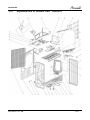
EXPLODED VIEW & SPARE PART LIST
15.8
15-8
Exploded view of outdoor unit: YDDE009, YDDE012
SM HDDE 1-A.1 GB
SERVICING
15.9
NO.
1
2
3
4
5
6
7
8
9
10
11
12
13
14
15
16
17
18
19
20
21
22
23
24
25
26
27
28
29
Spare part list of outdoor Unit: YDDE009
Part Code
G02613858
G02613862
G30148854
G43130184
G420111041
G71010003
G22413007
G01533034P
G10333004
G02803037P
G1501308502
G26233100
G01253073
G01703104
G01163812
G01473009
G4300876701
G07130369
G3900030804
G07133474
G07100003
G0171314201P
G26233433
G0130317801
G03073151
G01233385
G49010109
G00103896G
G06123401
SM HDDE 1-A.1 GB
Part Description
Electric Box Assy
Electric Box Sub-Assy
Main Board
Reactor
Terminal Board
Wire Clamp
Front Grill
Front Panel
Axial Flow Fan
Chassis Sub-assy
Brushless DC Motor
Small Handle
Top Cover Sub-Assy
Motor Support
Condenser Assy
Rear Grill
Magnet Coil
Electronic Expansion Valve
Temperature Sensor
Cut off Valve Assy
Valve
Valve Support
Big Handle
Right Side Plate Sub-Assy
4-Way Valve Assy
Clapboard Sub-Assy
Magnetic Ring
Compressor and Fittings
Drainage Connecter
qty
1
1
1
1
1
1
1
1
1
1
1
1
1
1
1
1
1
1
1
1
1
1
1
1
1
1
1
1
1
15-9
EXPLODED VIEW & SPARE PART LIST
15.10
NO.
1
2
3
4
5
6
7
8
9
10
11
12
13
14
15
16
17
18
19
20
21
22
23
24
25
26
27
28
29
15-10
Spare part list of outdoor Unit: YDDE012
Part Code
G02613643
G02613666
G30148856
G43130184
G420111041
G71010003
G22413007
G0153303204P
G10333427
G02803279P
G1501306719
none
G01253443
G0170310401
G01163898
G01473057
G4300876701
G07133818
G3900030805
G071302391
G07100003
G01713169
G26233433
G0130317801
G03073136
G0123314201
G49010109
G00103896G
G06123401
Part Description
Electric Box Assy
Electric Box Sub-Assy
Main Board
Reactor
Terminal Board
Wire Clamp
Front Grill
Front Panel
Axial Flow Fan
Chassis Sub-assy
Fan Motor
Small Handle
Top Cover Plate
Motor Support
Condenser Assy
Rear Grill
Magnet Coil
Electric Expansion Valve Sub-Assy
Temperature Sensor
Cut off Valve
Valve
Valve Support Assy
Big Handle
Right Side Plate Sub-Assy
4-Way Valve Assy
Clapboard Sub-Assy
Magnetic Ring
Compressor and Fittings
Drainage Connecter
qty
1
1
1
1
1
1
1
1
1
1
1
0
1
1
1
1
1
1
1
1
1
1
1
1
1
1
1
1
1
SM HDDE 1-A.1 GB
SERVICING
15.11
Exploded view of outdoor unit: YDDE018
SM HDDE 1-A.1 GB
15-11
EXPLODED VIEW & SPARE PART LIST
15.12
NO.
1
2
3
4
5
6
7
8
9
10
11
12
13
14
15
16
17
18
19
20
21
22
23
24
25
26
27
28
29
30
31
32
15-12
Spare part list of outdoor Unit: YDDE018
Part Code
G10335008
G1501506402
G01705036
none
G4300040033
G03073158
G01473043
G26235401
G3900030901
G01163935
none
none
G01255005P
G01305093P
G20113003
G02613677
G420111041
G26235254
none
G01715010P
G0713506803
G0713506703
G0130509402P
G02803207P
G06123401
G0681340101
G01535013P
G22415002
G00105249G
G43130025
G01233153
none
Part Description
Axial Flow Fan
Fan Motor
Motor Support Sub-Assy
Electric Box (Fireproofing)
Magnet Coil
4-Way Valve Assy
Rear Grill
Left Handle
Temperature Sensor
Condenser Assy
Electronic Expansion Valve assy
Electric Expand Valve Fitting
Top Cover
Left Side Plate
Insulating Plate of Electric box Cover
Electric Box Assy
Terminal Board
Handle
Capacitor CBB61
Valve support assy
Cut off Valve
Cut off Valve
Right Side Plate
Chassis Sub-assy
Drainage Connecter
Drainage Plug
Front Panel
Front Grill
Compressor and Fittings
Reactor
Clapboard Assy
Capacitor CBB65
qty
1
1
1
0
1
1
1
1
1
1
0
0
1
1
1
1
1
1
0
1
1
1
1
1
1
3
1
1
1
1
1
0
SM HDDE 1-A.1 GB
SERVICING
15.13
Exploded view of outdoor unit: YDDE024
SM HDDE 1-A.1 GB
15-13
EXPLODED VIEW & SPARE PART LIST
15.14
NO.
1
2
3
4
5
6
7
8
9
10
11
12
13
14
15
16
17
18
19
20
21
22
23
24
25
26
27
28
29
30
31
32
33
34
35
15-14
Spare part list of outdoor Unit: YDDE024
Part Code
G22415003
G1501403402
G20113027
G49010252
G30148864
G02613662
none
G420111041
G26235401
G01305043P
G01255006P
G01705025
G01175092
G01233164
G01163917
G01475013
G26115004
G3900030901
none
G0130504401P
G26235001
G07133157
G0171501201P
G01365435P
none
G03073144
G4300040045
G76710247
G00105249G
G06123401
G02803255P
G06813401
G10335009
G01305086P
G01435004P
Part Description
Front Grill
Fan Motor
Electric Box (Fireproofing)
Radiator
Main Board
Electric Box Assy
Terminal Board Support sub-assy
Terminal Board
Left Handle
Left Side Plate
Top Cover
Motor Support Sub-Assy
Condenser support plate
Clapboard Assy
Condenser Assy
Rear Grill
Wiring clamp
Temperature Sensor
Capacitor CBB61
Right Side Plate
Big Handle
Cut-off Valve
Valve Support Sub-Assy
Baffle (valve support)
Capillary Sub-assy
4-Way Valve Assy
Magnet Coil(4-way Valve)
Compressor Gasket
Compressor and Fittings
Drainage Connecter
Chassis Sub-assy
Drainage Hole Cap
Axial Flow Fan
Front Side Plate
Cabinet
qty
1
1
1
1
1
1
1
1
1
1
1
1
1
1
1
1
1
1
0
1
1
1
1
1
1
1
1
3
1
1
1
3
1
1
1
SM HDDE 1-A.1 GB
SERVICING
16.
SERVICING
16.1
Servicing procedure of indoor units
16.2
Servicing procedure of outdoor units
SM HDDE 1-A.1 GB
15-15
APENDIX
APPENDIX
SM HDDE 1-A.1 GB
a
SERVICE MANUAL
HDDE009/012/018/024
SM HDDE 1-A.1 GB
15-15