1
MONITOR ISM™ V4.2
LCD Keypad
User's Guide
Contents
About This Guide............................................................................................................................................. ii
Notices ........................................................................................................................................................... iii
Welcome.......................................................................................................................................1
Introduction to Security Management ..............................................................................................................2
The MONITOR ISM™ LCD Keypad ................................................................................................................8
Common Tasks ...............................................................................................................................................9
Alarms, Arming and Disarming................................................................................................13
Alarm Monitoring Features ............................................................................................................................14
Audible Keypad Tones ..................................................................................................................................14
Sirens ............................................................................................................................................................15
Dealing with Alarms (what to do if the keypad is beeping) .............................................................................15
Silencing a False Alarm.................................................................................................................................15
Using the Emergency Keys ...........................................................................................................................16
Worklate: Extending the Scheduled Closing Time ........................................................................................16
Suspending Schedules for an Area or Areas .................................................................................................17
Arming/Disarming or Viewing the Present Arming-Level ...............................................................................17
UK System Operation....................................................................................................................................19
UK and European System Operation.............................................................................................................19
Checking Status and Controlling Items ..................................................................................21
Status and Control Features..........................................................................................................................22
Using the Function Keys................................................................................................................................22
Checking the System Status (monitored conditions for a panel) ....................................................................22
Checking the Status of Sensors (Points) and Areas ......................................................................................23
Bypassing a Faulty Sensor ............................................................................................................................23
Checking Status or Controlling Readers or Doors .........................................................................................24
Checking the Status of a Suite Security Unit (Condo) (Suite Security/Multi-Tenant Keypad).........................25
Checking the Status or Controlling an Elevator Reader .................................................................................25
Checking the Status of an Application Module (Printer).................................................................................25
Administration and Maintenance Tasks .................................................................................27
Changing Your Own PIN ...............................................................................................................................28
Adding a User to the System .........................................................................................................................28
Viewing or Changing Settings for a User .......................................................................................................29
Deleting a User..............................................................................................................................................30
Setting the Date and Time .............................................................................................................................31
Viewing the History........................................................................................................................................31
Printing the History Log .................................................................................................................................32
Changing the Printed History Language ........................................................................................................32
Testing Monitored Sensors (Performing a Walk Test) ..................................................................................33
Testing Panic Buttons (Performing a Holdup Test) ........................................................................................34
Testing Sirens (System Test) ........................................................................................................................34
Reference Topics .....................................................................................................................35
System Information (Areas, Authorities, etc.).................................................................................................36
Residential Fire Safety / Evacuation Plan ......................................................................................................44
Arming Station Reference..............................................................................................................................46
Wireless Keypad Reference ..........................................................................................................................49
Error Messages and Trouble Indications .......................................................................................................50
21-0375v4.2 (5. 2003)
© 2003 CSG Security Inc. / Sécurité CSG Inc.
i
Copyrights and Trademarks
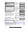
About This Guide
This guide provides details on performing
various tasks in a MONITOR ISM™ system
using an LCD keypad.
Firmware Revisions: This manual can be used with
panel firmware V2.x and V3.x, but be aware that:
+ Support for controlled elevators and floors
pertains to panels with V3 firmware and newer.
+ Support for 9-digit card ID/No. and card version
numbers pertains to panel firmware ≥ V3.20, and
door and elevator (lift) controller firmware ≥ V1.5.
™ MONITOR ISM is a trademark of CSG
Security Inc. / Sécurité CSG Inc.
™ Pentium is a trademark of Intel Corporation
™ ® Microsoft, Windows, Windows95, and
Windows98, are trademarks or registered
trademarks of the Microsoft Corporation.
© Copyright 2003
CSG Security Inc. / Sécurité CSG Inc.
All rights reserved.
To locate a desired topic, refer to the table of
contents (near the front of this guide), or the
Index (near the back of this guide).
Tip: The bottom of each odd-numbered page also
gives an indication as to your general position within
this guide.
Also See (Related Documents)
For details on using the MONITOR ISM™
Director software, refer to the on-line help or
User's Guide provided with the software.
For details on installing components, refer to
the installation sheet provided with each
specific device.
Disclaimer
In the interests of ongoing improvement in
quality and design, we reserve the right to
change product specifications without prior
notification. All software, firmware, drawings,
diagrams,
specifications,
catalogues,
literature, manuals and other materials relating
to the design, use, and service of related
products shall constitute the proprietary
information of the manufacturer.
For details on setting up a new system, and
performing other technical tasks, refer to your
system commissioning reference manual.
ii
MONITOR ISM™ LCD Keypad User's Guide
21-0375v4.2
Industry Canada Notice of Limitations
Notice: The Industry Canada Label identifies
certified equipment. This certification means
that the equipment meets telecommunications
network protective, operational and safety
requirements as prescribed in the appropriate
Terminal Equipment Technical Requirements
documents(s).
The Department does not
guarantee the equipment will operate to the
user's satisfaction.
Before installing this equipment, users should
ensure that it is permissible to be connected to
the facilities of the local telecommunications
company.
The equipment must also be
installed using an acceptable method of
connection. The customer should be aware
that compliance with the above conditions may
not prevent degradation of service in some
situations.
Repairs to certified equipment should be
coordinated by a representative designated by
the supplier. Any repairs or alterations made
by the user to this equipment, or equipment
malfunctions,
may
give
the
telecommunications company cause to
request the user to disconnect the equipment.
Users should ensure for their own protection
that the electrical ground connections of the
power utility, telephone lines and internal
metallic water pipe system, if present, are
connected together. The precaution may be
particularly important in rural areas.
Caution: Users should not attempt to make
such connections themselves, but should
contact the appropriate electric inspection
authority, or electrician, as appropriate.
Ringer Equivalence Number (REN): The REN
assigned to each terminal device provides an
indication of the maximum number of terminals
allowed to be connected to a telephone
interface. The termination on an interface may
consist of any combination of devices subject
only to the requirement that the sum of the
Ringer Equivalence Numbers of all the devices
does not exceed 5.
The REN for the MONITOR ISM is: 0.1
21-0375v4.2 (5. 2003)
© 2003 CSG Security Inc. / Sécurité CSG Inc.
iii
FCC Class A Digital Device Notice
This device complies with Part 15 of the FCC Rules.
Operation is subject to the following two conditions:
(1) this device may not cause harmful interference
and (2) this device must accept any interference
received, including interference that may cause
undesired operation.
This equipment has been tested and found to
comply with the limits for a Class A digital
device, pursuant to Part 15 of the FCC Rules.
These limits are designed to provide
reasonable
protection
against
harmful
interference when the equipment is operated
in a commercial environment. This equipment
generates, uses, and can radiate radio
frequency energy and, if not installed and used
in accordance with the instruction manual,
may cause harmful interference to radio
communications. Operation of this equipment
in a residential area is likely to cause harmful
interference in which case the user will be
required to correct the interference at his own
expense.
Warning: Changes or Modifications not expressly
approved by CSG Security Inc. could void the user's
authority to operate the equipment.
iv
Customer Instructions pertaining to
FCC Regulations
This equipment complies with Part 68 of the
FCC rules. On the casing of this equipment is
a label that contains, among other information,
the FCC registration number and ringer
equivalence number (REN) for this equipment.
If requested, this information must be provided
to the telephone company.
This equipment is designed to be connected to
the telephone network or premises wiring
using a hard wired connection that does NOT
rely on a modular jack. If a modular jack is
installed, it is the responsibility of the installing
company to ensure that the jack and/or plug
comply with FCC Part 68 requirements.
Applicable Jack USOC: RJ-11 (Dependent
on type of equipment, i.e. Standard modem,
Digital TE, Tie-Trunk)
The REN is used to determine the quantity of
devices which may be connected to the
telephone line.
Excessive REN's on the
telephone line may result in the devices not
ringing in response to an incoming call. In
most, but not all areas, the sum of REN's
should not exceed five (5.0). To be certain of
the number of devices that may be connected
to a line, as determined by the total REN's,
contact the local telephone company.
MONITOR ISM™ LCD Keypad User's Guide
21-0375v4.2
If the terminal equipment (MONITOR ISM)
causes harm to the telephone network, the
telephone company will notify you in advance
that temporary dis-continuance of service may
be required.
But if advance notice isn't
practical, the telephone company will notify the
customer as soon as possible. Also, you will
be advised of your right to file a compliant with
the FCC if you believe it is necessary.
The Telephone Company may make changes
in its facilities, equipment, operations or
procedures that could affect the operation of
the equipment. If this happens the telephone
company will provide advance notice in order
for you to make necessary modifications to
maintain uninterrupted service.
If trouble is experienced with this equipment
(MONITOR ISM™), please contact the
installing company for repair or warranty
information.
If the equipment is causing harm to the
telephone network, the telephone company
may request that you disconnect the
equipment until the problem is resolved.
UL Listed Systems
For UL-listed systems, weekly testing of the
bell/siren is required.
For details, refer to "Testing Sirens (System
Test)" (in the Admin. section).
As well, users should be cautioned against
giving out their entry codes (ID and PIN).
Where someone requires casual access to the
system (cleaner, baby-sitter, etc.), a new user
record should be set up with appropriate
authorities.
To set up a new user, refer to "Adding a New
User".
The following features have not been tested for UL
certification. Features pertaining to:
+ A wireless (handheld) keypad;
+ Communications with the MONITOR ISM Director
software;
As of this writing, UL and ULC testing is pending on
elevator controllers, Suite Security LED keypads and
related features.
There are no user serviceable parts which
may be repaired by the customer. All repairs
must be performed by an authorized dealer
representative.
This equipment cannot be used on public coin
phone service provided by the telephone
company. Connection to party line service is
subject to state tariffs. (Contact the state
public utility commission, public service
commission or corporation commission for
information.)
21-0375v4.2 (5. 2003)
© 2003 CSG Security Inc. / Sécurité CSG Inc.
v
#
vi
MONITOR ISM™ LCD Keypad User's Guide
21-0375v4.2
Welcome
21-0375v4.2
Welcome
Alarm
Status
Admin
Reference
1
Introduction to Security Management
General Concepts
Seamlessly Integrated Security
MONITOR ISM™ systems provide a seamless
integration between managing system security
and controlling personnel access at the facility.
This provides assurance that unauthorized
access will be detected for immediate
attention, while allowing authorized persons to
enter at their designated doors and times
without triggering an alarm.
Feature-Rich Security
The monitoring of doors, windows, and areas
within the facility can be uniquely customized
to meet even the most stringent requirements
for a wide array of applications and situations.
The interweaving of characteristics for 'areas'
and individual devices, in conjunction with
authority assignments for groups of persons
provides a feature-rich environment for
monitoring activity, maintaining security, and
managing personnel.
Access Control (Who can go Where and When)
In its simplest sense, access control is the
management of WHO can go WHERE and
WHEN. With the addition of door-control
modules, user-access can be controlled
throughout a facility as desired.
Persons authorized to enter the facility are
(typically) given an access card or token,
which will allow access only to specific doors
at applicable times as per the person's
assigned authority profile. Each reader may
require entry of a PIN, and/or the presence of
an assigned escort (escort mode) or any
second valid user (dual custody) before the
door will unlock.
Doors can also be set to unlock and re-lock or
change operating characteristics automatically
at desired times. Area characteristics can also
be automated based on a desired schedule,
and area(s) can be set to disarm automatically
whenever specific persons are granted entry.
2
Activity Monitoring and Signalling
Activity that occurs at each site can be viewed
through the MONITOR ISM Director software,
and can also be transmitted to a Central
Monitoring Station.
How sensors are monitored--and events signalled, is
based on the settings for the specific device and its
associated "area", in conjunction with the arming
level that is presently in effect for each specific area.
Panels with non-shared dial-up connections (or IP if
≥ v3.3) can be set to automatically dial-in and
transfer alarms, or blocks of activity messages to a
Director PC. Alarms and events are also transmitted
when a connection is made with the specific
panel(s)—either manually, or at scheduled times.
Centrally Monitored Systems
Centrally-monitored systems are connected to
a 24-hour ULC listed Monitoring Station
through telephone lines (dial-up), or through an
IP connection (SIP Reporting). When the
control panel detects an intrusion, fire, panic or
other alarm, it automatically signals the
monitoring facility.
Emergency response
operators will notify the appropriate local
authorities in the area. Where by-laws require,
alarms will be verified first.
A local alarm on your premises may not be
enough to scare away some intruders, so most
agree that a monitored system is a required
deterrent. As well, only a centrally monitored
system can provide this extra measure of
protection in the event of fire and other
emergencies.
Messages are transmitted to a monitoring station via
the 'Bell 103' (300 baud) modem support built into
each main panel, and/or an IP connection (Security
Internet Protocol Reporting)
SIP Reporting is supported beginning with v3.30
Director software and panel firmware.
Guard Tours
Through the MONITOR ISM™ Director
software, the routes taken by Guards can be
initially set up, and then monitored for a
specific user (guard) at any time. Each 'tour'
MONITOR ISM™ LCD Keypad User's Guide
21-0375v4.2
will consist of chosen access-controlled doors,
plus additional guard tour stations (checkpoints) that my be key-switches, or other types
of input points—along with the acceptable time
for the guard to arrive at each location.
Reporting
No security management system would be
complete without the ability to generate
reports. The MONITOR ISM Director software
provides an extensive list of customizable
reporting features, including various Time and
Attendance reports, Guard-Tour reports,
activity reporting (including Who went Where
and When), plus printouts of the users and
configured settings for a specific account.
These reports can be viewed and/or printed,
and many can be saved as a text file, or
archived in a viewable format.
Paging
The paging feature of the MONITOR ISM
system allows the triggering of certain outputs
(up to 12 separate outputs per panel) to
automatically send a message to a numeric
pager, letting the wearer know that a certain
event has occurred (e.g., forced entry, SNAPP
failure, fire, etc.). The specific events to be
notified though the pager can be customized
as desired through the programmable outputs
configuration.
Device Control
Items can be controlled both by an authorized
user at an alarm keypad, and by an operator
using the MONITOR ISM Director software.
Some examples include bypassing sensors,
arming and disarming areas, and unlocking or
re-locking doors, or changing the operating
characteristics for doors (by 'area', or for
individual doors).
Actions can also be
scheduled to occur automatically at desired
times, or when a specific event occurs (such
as when an area is disarmed, or when a fire
alarm occurs, etc.).
software licensing, up to 60 suite security
keypads with LED display are supported per
system panel, with 8 users supported per suite.
• Multiple-Tenant Support: User authorities can
be limited to working with a specific range of
users and user authorities. This allows a multitenant facility (such as a row of shops) to be
managed through a single system.
• High-Security Areas and Vault Auto-Arming:
Areas can be 'interlocked' so only one of them
can be disarmed at a time. Vault/safe areas
can be auto-armed when an attendant closes
the door.
• Door Interlock: Doors can be set to disallow
user access until up to 3 other specific doors
have been closed (and re-locked) for a specific
period of time. This allows limiting the number
of persons who can enter in close proximity,
and/or the speed at which persons can enter a
specific area.
• Master Override: A security officer can be
given the authority to enter doors that would
normally deny access (cards locked out, wrong
time, etc.).
Exceptions: Master override does not affect 'dual
custody', card/PIN mode, or door 'interlock' issues.
• Panic Token: Wireless (RF) panic tokens allow
for locally or centrally-monitored personal
protection.
• Wandering Patient Control: Patients can be
equipped with 'smart' wristbands, allowing their
presence to be detected as they approach
exterior doors, or other locations that may be of
concern. An alarm can be triggered, and the
door can optionally lock as the patient
approaches. Specific staff members can be
given the authority to cancel the alarm by
presenting their token at the specific door.
• Special Types of Input-Points: In addition to
allowing input-point monitoring to be fully
customized as desired, custom input-point
types can be set up to allow monitoring garage
door sensors, vault/safe inputs, arm/disarm
keyswitches, Guard-Tour station inputs, and
work-late buttons.
Special-Use Features
A number of features are provided for special
applications, including:
• Suite Security Support: Depending on
21-0375v4.2
Welcome
Alarm
Status
Admin
Reference
3
System Components and Software
System Software and Licensing
The MONITOR ISM™ Director Software
The MONITOR ISM Director software provides
a familiar Windows interface supporting these
easy-to use features:
• An authorized technician (service user) can
configure all aspects of the system;
• Authorized admin. persons have the ability to
easily manage personnel, monitor activity, and
perform typical maintenance tasks.
• Customizable access to specific status and
control features provides up-to-the-minute
status and manual-control ability on an areaby-area basis, or for individual doors or
sensors (input points).
• The software can be run on a single-PC, or
across multiple PCs in a client-server
arrangement.
MONITOR ISM Director is compatible with
MONITOR ISM alarm systems—which in turn
support many types of system modules and
related hardware.
4
The MONITOR ISM Director software (and the
on-line help) run under Windows9x/Me and
Windows 2000/NT.
Software versus Panel Firmware Revisions:
Monitor ISM Director software ≥ V3.20 is compatible
with panel firmware v2.0 and higher. Software
V3.0x and older is compatible only with firmware of
the same basic revision level as the software.
Customizable Desktop
The MONITOR ISM™ Director interface can
be set as desired by each individual operator.
This includes whether they prefer the MyTools
bar, or the Tree window, plus the sizing of the
desktop sections, and other settings. (The
MyTools bar can also be totally customized as
to the items it contains, what each item is
called, and the order (sequence) of the items.)
As well, the desktop will show only the features
and items that are available to each specific
operator (as per their assigned permissions).
MONITOR ISM™ LCD Keypad User's Guide
21-0375v4.2
Dual-Language Framework
The MONITOR ISM system provides a
framework for dual-language support, allowing
for dual-language installations, as new
language-versions of the software and panels
become available.
Once installed in the desired languages
(subject to availability), operators and users
can be set as to their preferred language—
allowing all operator screens, on-line help,
and/or LCD-keypad screens to appear in the
appropriate language for the person who is
presently logged in.
Single-language localized versions of the software
may also become available to allow for languages
that cannot be supported concurrently with other
character-sets.
Software Licensing and Activation Key
System capacities and types of expansion /
application modules supported depends on the
software version and licensing, which is
managed through the 'activation key' on the
parallel port of the server (or only) PC.
Software Demonstration Mode: If the activation key
is not installed on the PC's parallel port (server PC if
client-server), these features will be disabled:
+ Panel-to-PC communications (plus all related
features);
+ Client-server operation.
For details on using the Monitor ISM Director
software, refer to the on-line help or User's Guide for
the software.
Software Versions and Basic Capacities
Enterprise Version:
• Multiple accounts, with multiple panels;
(additional panels allow for additional areas /
sensors, doors, outputs, etc.)
• Full client/server support;
• Support for up to 60 Suite Security units;
• 32 access-controlled doors per panel
(with 1 or 2 readers per door);
• Up to 32 access-controlled elevator cabs per
panel (shared with the door capacity--max. 32 total);
• 124 unique floors (in a single building or multiple
buildings);
• Up to 1000 authority profiles for users;
• Up to 64000 users / cardholders.
Prime Version:
• One Account, with one system panel;
•
•
•
•
•
Single PC (no client/server support);
No suite security or elevator support;
16 Door capacity (1 or 2 readers per door);
100 authority profiles for users;
1000 users / cardholders.
The lists above show only the items that are different
between the two system versions. For a full list of the
items supported, refer to either the system commissioning reference guide, or the user's guide or on-line
help for the MONITOR ISM Director software.
Systems set for capacities higher than as shown under
"Prime" (above) can be configured only through the
MONITOR ISM Director software.
Some of the capacities that follow also require
additional panel memory to be installed.
System upgrades may involve a combination
of upgrading software, hardware, and/or
licensing (refer to the instructions provide with
the upgrade kit).
21-0375v4.2
Welcome
Alarm
Status
Admin
Reference
5
Overview of Tasks
(What can be Done from Where)
Adjusting the 'Closing' Time (Worklate) for an Active Schedule
The 'closing' time for a schedule can be
adjusted:
• By an authorized operator using the MONITOR
ISM Director software.
• By an authorized user/entrant at a system LCD
keypad;
Cardholder Administration
The administration of users/cardholders can be
done:
• Through this MONITOR ISM Director Software
(via modems or direct-connect);
• Locally through a system keypad (with 2-line
LCD display).
System Configuration
System/panel configuration can be done:
• By an authorized user/entrant at an 'arming
station' enhanced reader;
• By an authorized operator (with "Configuration"
permissions) through this MONITOR ISM
Director Software;
• By pressing a 'worklate' button (inside the
controlled-access facility);
• Locally through an alarm system's keypad
module (by an authorized technician).
Work-late buttons are set up as custom input-point
types.
Arming / Disarming Areas
The arming and disarming of a system and/or
individual areas can be:
• Linked to an Event--such as when an exit door
closes (Area settings), or when an authorized
person is granted access (Authority settings);
• Set to occur automatically at specific times
(Schedules and Area settings);
System configuration through the MONITOR ISM
Director software is supported through a directcable-connection or a dial-up (modem) connection to
associated panel(s).
All system configuration
requires knowledge of the 'Service PIN'.
Local user admin. (via keypad) is supported in all
systems, while local system configuration is
supported only in single panel systems set to
"Memory Model" 1, 2, 3, or 4. Exception: Keypad
programming is supported in all systems for any
'application' modules that require this due to custom
settings stored only at the module itself (Printer, RF
Wireless modules).
• Performed through the MONITOR ISM Director
software—by an authorized operator;
• Performed by an authorized user/entrant at an
'arming station' enhanced reader;
• Performed locally through a system LCD
keypad by an authorized user (similarly, a suite
unit can be armed and disarmed through a
'Suite Security' LED keypad).
• Performed using a custom "arm/disarm
keyswitch" input-point.
6
MONITOR ISM™ LCD Keypad User's Guide
21-0375v4.2
Avoiding False Alarms
No matter how full-featured, and reliable a
security system is, a number of steps must be
taken to absolutely minimize the likelihood of
false alarms occurring. These include:
1)
Ensuring the system's configuration
accurately reflects the requirements at the
site (regarding the working times and
movement of personnel during a typical
workweek, etc.).
2)
Knowing how the police and fire departments
handle false alarms, and ensuring
appropriate procedures have been set up
with the monitoring station. For example,
identifying the types of alarms where an offsite security or maintenance person is to be
called either first, or instead of the police.
3)
Ensuring all authorized persons know "where
they can go and when", and have received
appropriate training on the system. For
example, how to disarm the area, adjust the
'work late' time, and perform other basic
tasks through an LCD keypad.
Tip: To greatly minimize false alarms pertaining to
personnel entering an armed area, the system will:
• Allow persons to enter only if they have the authority
to disarm the applicable area, or:
• Disarm the area automatically when the person is
granted entry (optional / if set for this).
21-0375v4.2
Welcome
Alarm
Status
Admin
Reference
7
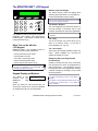
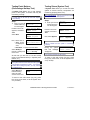
The MONITOR ISM™ LCD Keypad
Buttons under the Display
The buttons directly under the display allow
selecting associated items on the display (i.e.,
the item indicated above each button).
1' - #
2
4 GHI
5 JKL
7
PRS
8
0
ABC
TUV
Z_Q
3
6 M NO
9
Like the rest of the keypad, these buttons are backlit
for use in poor lighting conditions.
DEF
WXY
X
f
Â
Â
X
X
The MONITOR ISM LCD keypad provides an
integrated 2-line display and multi-function
backlit keypad. (The keypad is hidden behind
a hinged access cover.)
What You can do with the
LCD Keypad
MONITOR ISM™ LCD keypads provide a
convenient local interface that allows:
• Arming and disarming the system;
• Checking status of items;
• Controlling / commanding items;
• Performing administrative tasks;
• Performing the initial system set-up.
Note: Initial set up is performed by an authorized
technician as described in the "MONITOR ISM
Commissioning Reference Guide".
Keypad Display and Buttons
The display is your Welcome
'window'
into
the Enter ID: _ _ _
MONITOR
ISM
system.
When you enter your user ID and/or PIN, you
will be given access to all menus and features
as assigned through your user authorities.
8
The Numeric Keypad
The main keypad (in the bottom-left portion of
the unit) provides a convenient way to enter
numbers, and letters as well (when applicable).
This keypad is fully backlit for use in poor lighting
conditions.
The 8 Key
This is the "escape" key, which allows you to
return to a previous screen, or exit from a
menu altogether (i.e., log out).
The ◄ and ► Keys
These keys allow selecting different items and
topics. When available, the ◄ and/or ►
symbol will appear on-screen.
Emergency Keys and Programmed
Function Keys
Pressing a number and the ƒ key at the same
time will perform the action as programmed for
that key-sequence. The emergency keys on
the right-hand side of the keypad each transmit
a specific emergency message ( to the central
monitoring station).
For more information on the emergency keys, refer
to "Using the Emergency Keys" in the "Alarms…"
chapter.
For details on the programmable function keys, refer
to "Using the Function Keys" in the "Status &
Control" chapter.
MONITOR ISM™ LCD Keypad User's Guide
21-0375v4.2
Common Tasks
Entering at an Access-Controlled Door
Reader/Door Mode
Area
Setting
Disarmed (Off)
Locked &
Card Only
Present card,
open the door
Locked &
Card+PIN
Locked &
Card or UID/PIN
Locked &
UID/PIN Only
Present card, enter PIN Present card or enter
open the door
user no., enter PIN
open the door
Enter UID+PIN (or PIN
only), open the door
Present card, enter PIN Present card or enter
open the door
user no., enter PIN
open the door
Enter UID+PIN (or PIN
only), open the door
Armed & 'Auto
Disarm on Valid
Token'
Present card,
open the door
Armed & 'PINOnly' or 'ID+PIN'
Present card, open the Present card, enter PIN
door. Then log into
open door. Then log
panel and disarm it.
into the panel & disarm
it.
Present card or enter
user no., enter PIN
open door. Then log
into the panel & disarm
it.
Enter UID+PIN (or PIN
only), open the door.
Then log into panel and
disarm it.
Armed &
Dual Custody
Present card, open the
door. Then login with
two user PINs (or
ID+PIN), & disarm
area.
Present card or enter
user no., enter PIN
open door. Then login
with two user PINs (or
ID+PIN), & disarm
area.
Enter UID+PIN (or PIN
only), open the door.
Then login with two
user PINs (or ID+PIN),
& disarm area.
Present card, enter PIN
open door. Then login
with two user PINs (or
ID+PIN), & disarm
area.
If the door is unlocked, access is not controlled
(simply open the door to enter the area).
Conversely, if the door is locked, and all cards are
presently 'locked out', users will be unable to enter.
To enter at a controlled door and disarm the area, an
entry delay must be in effect. As well, only the users
with authority to both enter the door at this time AND
disarm the area will be granted entry.
The 'ID + PIN' or 'PIN Only' login requirement is
determined by the "Memory Model" as set by the
service
technician
(via
S002:0).
Dual Custody (and Escort mode) is supported at
individual readers as well.
Using an Arming Station: Additional features
and entry options are provided through an
arming station. These units are essentially a
proximity reader with keypad, plus additional
status indicators and features. For details on
using an arming station, please refer to
"Arming Station Reference" near the back of
this guide.
21-0375v4.2
Welcome
Alarm
To Enter using a Door-Opener Button: Use
your access card and/or PIN to unlock the door
(and activate the button). Then, simply press
and release the door-opener button. Once
inside the area, 'log' in at an LCD keypad, and
disarm the area if required (i.e., if NOT set for
"Auto-Disarm on Valid Token").
To Exit Using an RTE Button: Simply press
and briefly hold the request-to-exit (RTE)
button.
If you Hold the Door Open: If the door is
held open for 'too long', a 'Door Held Open'
message will be logged.
A person holding a door open, or indicating that they
are being forced to enter may also trigger an alarm
(depending on the monitoring settings for the specific
door).
Status
Admin
Reference
9
If You Are Being Forced to Enter
Overview of Screens (Topics)
A duress (panic) alarm is triggered when you
enter your PIN with the last two digits
reversed.
(This can be done at reader
keypads, system LCD keypads, and Suite
Security LED keypads.)
When logged in, you will see only the topics
that you have the authority to use. Some or all
of the following topics will be available:
Normal PIN Example: 1 2 3 4
If being forced to Enter: 1 2 4 3
This feature will be available unless it was disabled
by your service technician when the system was
initially set up.
Logging Into the Keypad
(User ID and/or PIN)
"Logging In" provides you with access to the
features of the LCD keypad. To log in:
Open the
cover, and
your user ID
and/or PIN
as indicated
display
keypad
key in
number
number
on the
Welcome
Enter ID: _ _ _
Your Name
Enter PIN: _ _ _ _
When finished viewing or entering items, you can
use the 8 key to exit (press multiple times as
needed--until the "login" screen appears). Tip: You
will also be logged out automatically if you do not
press any keys for approximately one (1) minute.
Selecting a Topic: Press the "►" key until your
desired topic appears on-screen. Then press the
key directly under your topic to select it.
Off // Stay // On: Push ► for Menus
↓Stay ↓On
The first screen that
you'll see allows you
to arm or disarm the area(s) as desired, or to
access other topics.
Only two of arm/disarm selections will appear
at a time—depending on the present armingstate of the area(s).
Status / View Status: This allows checking
the status of various items in the system, or
commanding items into different states.
Additional status screens (Comms, Modem, and
Licns) are accessible by a service technician (i.e.,
service login). These pertain to service issues which
are not pertinent to this guide.
Bypass:
This allows bypassing faulty
sensor(s) so the system ignores them, and/or
to allow arming the system.
History / View History: This allows viewing a
record of the tasks that users have performed
(disarm areas, bypass sensors, etc.)
PIN: This allows the person who is logged in
to change their password.
Users: This allows adding or deleting 'users'
from the system, or viewing or editing settings
for specific users.
A "User" is a person who has the authority to login to
system keypads, and/or to gain entry at accesscontrolled doors.
Test: This allows testing different aspects of
the system.
Config: This allows a service user (person
with the service login ID and PIN) to set up a
new system, add devices to an existing
system, and/or view or change operational
settings for various items in the system.
10
MONITOR ISM™ LCD Keypad User's Guide
21-0375v4.2
Time: This allows changing the time and/or
date for a system panel.
Verify: This allows a person to prove they are
present. This lets a monitoring facility know
that you are present after accidentally tripping
a sensor, and/or silencing a false alarm.
Schdule: This allows extending the scheduled
closing time for an area (the "work-late"
feature), or suspending a schedule altogether.
Keypad Entry Basics
Use the buttons directly under the display to
select items indicated on-screen.
The ◄ and ► buttons allow you to view
additional topics--when available.
("◄" and/or "►" will appear on the display to
indicate these keys can be used).
Use the 8 key when finished with your present
menu / topic.
Entering Letters (e.g., for a user's name)
The numeric keypad allows entering numbers-and letters as well--for items that support this.
When required, press the specific key multiple
times until the desired letter appears:
Pressing "2" multiple times yields: 2 A B C.
Pressing "3" multiple times yields: 3 D E F
...etc. (look for the letters on each key).
Tip: The "_" on the 0 key (zero) represents a space.
21-0375v4.2
Welcome
Alarm
Status
Admin
Reference
11
#
12
MONITOR ISM™ LCD Keypad User's Guide
21-0375v4.2
Alarms, Arming
and Disarming
21-0375v4.2
Welcome
Alarm
Status
Admin
Reference
13
Alarm Monitoring Features
Depending on how the system is set up,
specific alarms may be indicated by any of the
following items:
• An alarm message will appear on specific
keypad(s);
• Keypad 'sonalerts' (beepers) may sound;
• A local siren may be triggered;
• An alarm message may be transmitted to a
central monitoring facility (and/or to a
management PC running the MONITOR ISM
Director software);
• A programmable "output" may be triggered
(this can cause a horn to sound, or perform
any other type of automated 'switching'
function);
• A numeric pager may be called to let the
wearer know that a specific type of alarm has
occurred.
These actions can be fully customized for each type
of event--for each arming level that the system can
be in at a given time (Off, Stay / Perimeter, or fully
ON).
Audible Keypad Tones
Error and Warning Tones
These tones are heard upon errors in keypad
entry, selection of wrong PIN numbers and to
indicate that there was an alarm (upon entry)
during the last armed period.
_
_
_
_
_
Very fast beep.
Trouble
This tone is heard when the system has a
problem (e.g. cut phone line) or the system
goes into alarm.
____________
Steady continuous tone.
Fire Alarm
__
__
_______
__
__
A repeating pattern with 0.5 seconds on, 0.5
seconds off. After 3 beeps (on), there is a 1.5
second delay, and then the cycle repeats.
Visual indications (lights and LCD menu
prompts) are complemented by audible tones.
These are as follows:
Confirmation of PIN/ID & PIN Entry
When Arming and Disarming
Single short beep
_______
_______
Slow intermittent beep (approx. @ 1 second
intervals).
Entry and Exit Delay Tones (last 15
seconds)
__
__
Chime
When the chime feature is turned on and a
door is opened.
__
__
Three short low level beeps.
__
Quick intermittent beep (approx. @ 1/2 second
intervals).
14
MONITOR ISM™ LCD Keypad User's Guide
21-0375v4.2
Sirens
Steps:
Conventional Siren
Fire Alarm: Intermittent Tone
(see previous details).
Burglar Alarm: Steady Tone.
Voice Siren (optional)
Fire Alarm: Steady tone, followed by
optional voice Fire Alarm Message.
(e.g. FIRE, FIRE ... Leave Immediately)
Burglar Alarm: Intermittent tone, followed
by optional voice Burglar Alarm Message.
(e.g. Intrusion, Intrusion ... The police have
been called, leave immediately).
Dealing with Alarms (what to do if
the keypad is beeping)
If an alarm occurs, you must first decide if it is
a valid alarm (break-in, battery failure, etc.), or
a false alarm. If a valid alarm occurs, be sure
to notify the appropriate persons, and/or take
steps to either deal with the item yourself--if
appropriate, or get yourself and others out of
harm's way.
Enter your user ID
and/or password to log
into the keypad.
!! In Alarm !!
Enter ID: _ _ _
Select Yes to silence
the alarm.
Silence System?
↓Yes ↓No View↓
Select Yes again to
verify who you are.
Verify User?
↓Yes ↓No
To Verify User
Enter your PIN when
Enter PIN: _ _ _ _
prompted. This will
signal the monitoring
facility that you wish to cancel the false alarm.
To disarm area(s),
select "Off".
Push ► for menus
↓Off ↓Stay
Select Yes to turn all
areas off.
All Areas Off?
↓Yes ↓No
If there was a false
alarm, the following
screen will appear.
Area XX
Had an Alarm
Select Ack to
acknowledge the
alarm and disarm the
system.
xxx: Sensor Name
Status
↓Ack
XXX: refers to the number for the monitored sensor
(input point) that was in alarm.
Silencing a False Alarm
An authorized user can Cancel a false alarm,
disarm the system and inform the monitoring
station not to dispatch the respective
emergency service.
Press this key to
perform another
function.
Disarming...
↓Next Function
This feature may not be available in all areas.
Consult your local security representative for more
information.
To return to the main screen (log out), press
the (8) key a few times, or let the system timeout (1 minute).
The ability to clear alarms requires "Service Test"
authority.
The entry tones will now stop sounding and the
selected areas are now fully disarmed.
The following steps assume that you have
accidentally triggered a false alarm. If an
alarm has been generated, the LCD display
will show the alarm, and the keypad 'sonalert'
may also be emitting a steady tone.
The Verify option must be selected within 1 minute of
the false alarm being generated, for the station to
acknowledge the signal.
21-0375v4.2
Welcome
Alarm
Status
Admin
Reference
15
Using the Emergency Keys
There are three emergency keys that will
activate an emergency alarm. This will be
transmitted to the monitoring facility, and may
also trigger a local alarm, activate a
programmable output, and/or trigger a numeric
pager (depending on how the system is set
up).
To transmit an emergency alarm, press the
button on both sides of the specific symbol at
the same time.
Emergency Keys
Worklate: Extending the
Scheduled Closing Time
In its simplest sense, a Schedule defines
business hours versus after-hours for the
system. If the scheduled closing time is
approaching, and you wish to remain in the
area, you can extend the 'closing' time.
Steps:
1. Enter your user ID
and/or PIN to log
into the keypad.
2. Press the ► key
until you see
"Schdule". Then
select Schdule.
Fire
Welcome
Enter ID: _ _ _
Menu Options ◄ ►
↓Verify ↓Schdule
3. Select Schd to
Panic/Police Alarm
Â
Emergency (Non medical)
AreaName.....Off
change the
↓Schd ↓Next Area
Schedule for the
selected area (e.g. Office) or select Next
Area to select a different area.
4. Select WorkLate
Emergency keys are available only if programmed by
your security representative.
Close by 09:30Mo
to change the
↓Worklate Susp↓
closing time for
your selected area.
5. Select "+" or "-"
to adjust the
closing time as
desired.
..Until
17:30
↓Ok
↓+ Adj -↓
The "+" and"-" (Adj) keys adjust the closing time by
increments of 30 minutes.
6. Once the
scheduled closing
time is correct,
select Ok.
..Until
17:30
↓Ok
↓+ Adj -↓
To return to the main screen (log out), press
the (8) key a few times, or let the system timeout (1 minute).
An authorized user may only change the WorkLate
Schedule for the current day. 15 minutes before a
Schedule ends, the system will chime indicating that
a scheduled closing is in effect. At this stage, an
authorized user may change the WorkLate time to
prevent the system from arming until a specified
time.
16
MONITOR ISM™ LCD Keypad User's Guide
21-0375v4.2
Suspending Schedules for an
Area or Areas
Arming/Disarming or Viewing the
Present Arming-Level
A schedule can be blocked altogether if you do
not want a scheduled closing to occur.
With the appropriate authority, you can arm
and disarm the system, or specific area(s)
using an LCD keypad.
Steps:
1. Enter your user ID
and/or PIN to log
into the keypad.
Welcome
Enter ID: _ _ _
Menu Options ◄ ►
until you see
↓Verify ↓Schdule
"Schedule". Then
press the key under "Schedule" to select it.
Steps:
1. Enter your user ID
and/or PIN to log
into the keypad.
2. Press the ► key
3. Select Schd to
Area..........Off
suspend the
↓Schd ↓Next Area
Schedule for the
selected area (e.g. Office) or select Next
Area to select a different area.
4. Select Susp to
suspend the
Schedule for the
selected area.
Close by 09:30Mo
↓Worklate Susp↓
5. Select Ok to
Suspended
suspend the
↓Ok Resume↓
schedule and
return to the main screen. Select Resume to
reinstate the schedule.
To return to the main screen (log out), press
the (8) key a few times, or let the system timeout (1 minute).
A Schedule will remain suspended indefinitely until
you select Resume.
2. Select the key for
your desired
arming-level.
Welcome
Enter ID: _ _ _
Push ► for menus
↓Stay ↓On
If all areas are currently OFF, only STAY and ON are
shown. If STAY is not an authorized function, only
ON will be shown.
The "Stay" arming-level pertains to the perimeter
sensors being monitored, but not the interior ones.
This is typically used when someone is inside the
facility or area.
Select No to choose
an Area to view or
change (or Yes for all
areas).
All Areas ON?
↓Yes ↓No
Press the left-most
button to set the
AreaName.....Off
↓On ↓Nxt Done↓
arming-level. Select
Nxt to choose a different area, or select Done to
exit.
Select OK to confirm.
(Review allows you to
change your mind.)
Area(s) to....ON
↓OK
↓Review
If points are currently bypassed, in tamper, in
alarm, or not Ok, the following screen will
appear when you are attempting to arm an
area (to Stay or ON).
Select Ok? to arm the
system, or View to list
points that are
currently not Ok.
Pts in Bypass!
↓Ok?
↓View
Selecting OK will arm the system with point(s) not
secure.
21-0375v4.2
Welcome
Alarm
Status
Admin
Reference
17
Points not Ok!
Select View to view
points that are
↓View
currently bypassed or
not Ok. At this time the system will indicate
points that are not OK and force you to either
bypass or secure these points in order to arm the
system.
Select the desired
AreaName.....Off
topic:
↓Pts ↓Next All↓
• Pts:
Bypassable points (sensors) in the
displayed area;
• Next: Show the next area;
• All: All bypassable points regardless of
area.
When a point/sensor
xxx: Sensor Name
is displayed, you'll
Status ↓Bypass ↓?
have these options:
• "►": Press this key to scan through the
sensors (points) in the system (or the
selected area);
• Bypass: Select this to have the system
ignore (bypass) the selected sensor.
• "" / "?": "" shows the area for the point.
"?" jumps to the next point that is not OK.
Once all points have Arming...Bypass
been bypassed or ↓Next Function
secured, the system
will automatically arm.
After arming (On),
leave immediately by
the designated exit
route!
Area(s) arming
Please Leave
The tone you will hear is a reminder for you to
quickly leave the area or premises. During the
last 15 seconds this intermittent tone will
become more rapid. The exit tones will now
stop sounding and the selected areas are now
fully armed.
18
MONITOR ISM™ LCD Keypad User's Guide
21-0375v4.2
UK System Operation
The following is required to ensure conformity
with the ACPO, DD243:2002 Standard.
If after disarming this Confirmed Alarm!
Enter ID: _ _ _
screen displays…
the system has had a
Confirmed Alarm and the following procedure
must be done:
Resetting Confirmed Alarms
Once a confirmed alarm occurs at a site, the
user will be able to disarm and silence the
system. The confirmed alarm strobe display, if
it is part of the system’s equipment, will also
turn off. However, arming will be blocked until
reset by an Engineer during a service call in
the following manner:
1. The main panel cabinet must be opened to
activate the ‘tamper sensor’
2. The system will generate a tamper alarm; the
authorized user must first silence this.
3. Next, the Service user ID and Pin must be
entered followed by the ID and Pin of the
authorized user.
4. Select “Reset Confirmed Alarm”.
5. Close the main panel cabinet to secure the
tamper sensor.
If there is an attempt made to arm the system
and this reset procedure has not been done, this
!! Cannot Arm !!
screen will appear
momentarily…
Confirmed Alarm!
External Arming Button
When attempting to arm the system and exiting
the protected area the “external arming button”
must be pressed. Failure to do so will result in a
“Failed to Exit” condition. The protection will
disarm at the end of the arming delay and a failed
to exit report will be logged in the system’s
History log.
UK and European System
Operation
Restoring Tampers
Once a tamper condition occurs it will be
logged in the system’s History log. Any
authorized users can silence tampers
21-0375v4.2
Welcome
Alarm
however; the following system message will
scroll on the LCD display to indicate that a
Was in Tamper!
Enter ID: _ _ _
tamper condition had occurred…
This message will only appear when the
tamper condition has been restored. The
yellow “trouble” light on the keypad will also
turn off.
1. This message can only be cleared during a
service call in the following manner.
2. The main panel cabinet must be opened to
activate the ‘tamper sensor’
3. The system will generate a tamper alarm; the
authorized user must first silence this.
4. Next, the Service user ID and Pin must be
entered followed by the ID and Pin of the
authorized user.
2nd Service User
This screen message
will display to prompt
Enter ID: _ _ _
for the master
authority user to enter their ID and Pin.
After the reset procedure has been completed,
the system Status can be checked to ensure that
the only tamper condition still displaying is the
open main panel cabinet.
5. Close the main panel cabinet to secure the
tamper sensor.
Arming / Disarming Conditions
If at the time of arming, certain system faults are
present, arming will be blocked.
The red armed light on the keypad will only stay
on for 30 seconds from the time of any arming.
This is to prevent the condition of the system
from being easily visible.
To view the armed state of the system, log in
from the “Enter ID:” screen. If all areas are ON
this screen will
All on
Menus ►
display:
↓Off ↓Stay
If one or some
areas are armed
this screen will
display:
Status
Admin
Partially Armed ►
↓Off
↓Stay
Reference
19
If a trouble condition occurred since the last
arming, this screen
System Fault or
will display on
Tampered
↓Ack
disarming…
When this screen is acknowledged (Ack) the
problem condition can only be seen by checking
system Status. If fault conditions are present,
than arrangements should be made to have them
corrected.
20
MONITOR ISM™ LCD Keypad User's Guide
21-0375v4.2
Checking Status
and Controlling
Items
21-0375v4.2
Welcome
Alarm
Status
Admin
Reference
21
Status and Control Features
Checking the System Status
Using an LCD keypad, you can:
(monitored conditions for a panel)
The system status feature shows the status of
all conditions (tamper, low battery, etc.) that
are being monitored for the panel associated
with your keypad.
• Check the status of various items in the system
and view the present arming-level of desired
area(s).
• Bypass faulty sensors to allow arming the
system and/or specific area(s);
• Command doors to Unlock, relock, or change
operating characteristics;
• Use the function keys to perform preprogrammed signalling and/or switching
functions.
Tip: The status of most items can be viewed on an
area-by-area basis, and the arming-level of each
area is also displayed;
Note: Additional status screens (Comms, Modem,
and Licns) are accessible by a service technician
(i.e., service login). These pertain to service issues
which are not pertinent to this guide.
These items may also be referred to as "Equipment"
settings, or "Pseudo-Points".
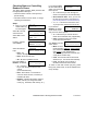
Steps:
1. Enter your user ID
and/or PIN to log
into the keypad.
Select ► to access
other functions.
Push ► for menus
↓Stay ↓On
Select Yes to view
Status.
View Status?
↓Yes ↓No
Select System.
View status of:
↓System ↓Points
Use the "?" selection
to scan through the
listed items.
Status Item
Using the Function Keys
LCD keypads provide 10 function keys that
can perform various signalling and/or switching
functions (as set up by your service
technician).
Function Key Reference: For a list of what your
function keys have been programmed to do, refer to
"System Information" in the reference section near
the back of this guide.
To use function key 1, 2, 3, 4, or 5, simply
press and hold the ƒ key, and press the
desired number at the same time.
Welcome
Enter ID: _ _ _
↓?
To return to the main screen (log out), press
the (8) key a few times, or let the system timeout (1 minute).
For details on the possible status messages, refer to
"Error Messages and Trouble Indications" in the
reference section near the back of this guide.
For function keys 6, 7, 8, 9, and 0, a user with
function-key authority may need to be logged
in to allow using these function keys.
This requirement is set on an area-by-area basis.
To log in, open the
keypad cover, and
key in your user ID
number and/or PIN
number as indicated
on the display.
Welcome
Enter ID: _ _ _
Your Name
Enter PIN: _ _ _ _
Then press and hold the ƒ key, and press the
desired number at the same time.
22
MONITOR ISM™ LCD Keypad User's Guide
21-0375v4.2
Checking the Status of Sensors
(Points) and Areas
The Points-status feature allows checking the
status of sensors in the system (and viewing
the arming-level for areas).
Steps:
1. Enter your user ID
and/or PIN to log
into the keypad.
Welcome
Enter ID: _ _ _
Select ► to access
other functions.
Push ► for menus
↓Stay ↓On
Select Yes to view
Status.
View Status?
↓Yes ↓No
Select Points.
View status of:
↓System ↓Points
Select the desired
AreaName.....Off
topic:
↓Pts ↓Next All↓
• Pts: Points
(sensors) in the displayed area;
• Next: Show the next area;
• All: All points regardless of area.
When a point/sensor
xxx: Sensor Name
is displayed, you'll
Status ↓Bypass ↓?
have these options:
• "►": Press this key to scan through the
sensors (points) in the system (or the
selected area);
• Bypass / Delbyp: Select Bypass to have
the system ignore the sensor (or "Delbyp"
to remove a "Bypass" that is in effect).
Also see: Bypassing a faulty sensor, to follow.
• "" / "?": "" shows the area for the point.
"?" jumps to the next point that is not OK.
Bypass appears only for points that are bypassable.
To bypass a sensor, the area cannot be armed (On).
If all points are OK,
you will see an "All
Secure" message.
All points in
area are secure
Bypassing a Faulty Sensor
If the system (or a specific area) needs to be
armed with a faulty or tripped sensor, you must
bypass the specific sensor.
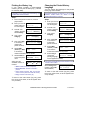
Steps:
1. Enter your user ID
and/or PIN to log
into the keypad.
Welcome
Enter ID: _ _ _
Menu Options ◄ ►
↓Bypass ↓History
Bypass appears
on the display.
Then, select Bypass.
2. Select ► until
To bypass a sensor, the area cannot be armed (On).
You can also bypass sensors through the Pointsstatus screens (see the preceding topic for details).
Select the desired
AreaName.....Off
topic:
↓Pts ↓Next All↓
• Pts:
Bypassable points (sensors) in the
displayed area;
• Next: Show the next area;
• All: All bypassable points in all areas.
When a point/sensor
xxx: Sensor Name
is displayed, you'll
Status ↓Bypass ↓?
have these options:
• "►": Press this key to scan through the
sensors (points) in the system (or the
selected area);
• Bypass / Delbyp: Select Bypass to have
the system ignore the sensor (or "Delbyp"
to remove a "Bypass" that is in effect).
• "" / "?": "" shows the area for the point.
"?" jumps to the next point that is not OK.
If all bypassable points No bypassable
points insecure
are secure, you will
see a related
message.
To return to the main screen (log out), press the (8) key
a few times, or let the system time-out (1 minute).
To return to the main screen (log out), press the (8) key
a few times, or let the system time-out (1 minute).
21-0375v4.2
Welcome
Alarm
Status
Admin
Reference
23
Checking Status or Controlling
Readers or Doors
The Door status screens allow persons with
the appropriate authority to:
• Check the status of doors in the system (or
specific areas);
• Command doors to unlock, relock, or change
operating characteristics.
Steps:
1. Enter your user ID
and/or PIN to log
into the keypad.
Welcome
Enter ID: _ _ _
Select ► to access
other functions.
Push ► for menus
↓Stay ↓On
Select Yes to view
Status.
View Status?
↓Yes ↓No
Press ►, and then
select Doors.
View status of:
↓Doors ↓Condo
(Condo: Suite Security)
Select the desired
AreaName.....Off
topic:
↓Door ↓Next All↓
• Door: For
doors in the displayed area;
• Next: Show the next area;
• All: All doors regardless of area.
Now select Door, or
D0x: Door Name
Readers, as desired:
↓Door ↓Readers
• "►": Press this
key to scan through the doors in the
system
(or the selected area);
• Door: Door status, or commands to
unlock or relock the door, or lockout (or
reinstate) all cards;
• Readers: Indicates the reader modes in
effect, and lets you change the reader
mode (e.g., Card+PIN, dual custody, etc.).
24
If you selected Door,
D0x: Door Name
the door state will be
↓DoorState
?↓
shown, and you'll have
these options:
• "►": Press this key to scan through the
doors in the system (or the selected area);
• Select the door state: Then, you can use
the ◄ ► keys to access a command (and
press the key under the command to select it);
• "" / "?": "" shows the area for the door.
"?" jumps to the next door that is not OK.
If you selected
D0x: Area Name
Readers, the reader
↓Cmd
RdrModes
mode will be shown,
and you'll have these options:
• "►": Press this key to view the second
reader for the selected door (if applicable);
• Cmd: Provides access to the reader
mode selections that follow.
Your Cmd choices are R0x: Area Name
↓Mode ↓Card ↓Lock
shown below:
• Mode: Access
modes including "Normal", "Dual Custody"
(two users/access cards needed to enter),
and "Escort" (a user identified as a
"Escort" must present their card first, then
a 2nd person w/valid card);
• Card: This includes various card-mode
selections (i.e., card and/or UID and PIN);
• Lock: This allows you to lockout or
reinstate card-access at this reader.
To return to the main screen (log out), press
the (8) key a few times, or let the system timeout (1 minute).
MONITOR ISM™ LCD Keypad User's Guide
21-0375v4.2
Checking the Status of a Suite
Security Unit (Condo)
Checking the Status of an
Application Module (Printer)
(Suite Security/Multi-Tenant Keypad)
You can check the status of any "application"
modules in the system.
(An application
module provides increased functionality such
as Printer capability.)
For systems that include Suite Security (multitenant) keypads, the MONITOR ISM Director
software is required to set up the system.
Due to the complexity of a typical Suite
Security installation, it is also recommended
that suite security status be checked only
through the software.
Each 'suite security' keypad pertains to an
individual multi-tenant suite or other selfcontained space.
As such, arm/disarm
functions are provided only through the suite
security keypads themselves.
UL / ULC Listed Installations: Suite Security
LED keypads have not been tested for UL or
ULC listing.
Checking the Status or Controlling
an Elevator Reader
For systems that include elevators, the
"Status" menus will include an "Elev" selection
for elevators and their associated readers.
The available selections will be the same as
for standard readers, as described in the
preceding section.
Attention:
All floor status and control
functions are available only through the
MONITOR ISM Director software. As such, it
is recommended that all elevator reader status
and control tasks be performed through the
software as well.
Exception: Checking a specific aspect of an
elevator reader can be performed through the
keypad (such as checking if it is in Card Plus
PIN mode), but you will have to log in at an
operator workstation to see if the floors are
secure.
UL / ULC Listed Installations: UL and ULC
testing is pending on elevator (lift) controllers
and related features.
21-0375v4.2
Welcome
Alarm
Steps:
POD (definition): "Module" - a controller
that e.g. connects a Printer to the system.
1. Enter your user ID
and/or PIN to log
into the keypad.
Welcome
Enter ID: _ _ _
Push ► for menus
↓Stay ↓On
2. Select ► to
access other
functions.
3. Select Yes to
View Status?
↓Yes ↓No
view status.
Status of? ◄ ►
↓Points
↓App
4. Select App to
view status of an
application
module.
ModuleName/Type ►
view the status of
↓Yes ↓No
the indicated
module (e.g. “HSC” for Printer), or use the ►
key to select another module.
5. Select Yes to
6. Select HSC and
then Printer to
view the status of
the Printer.
Pod Status . . . .
↓Printer
The status screen will
PRN(printer):OK
indicate if the system
POD:OK
device is Ok or
disabled and any device related information.
Select Next to view status of the next module.
To return to the main screen (log out), press
the (8) key a few times, or let the system timeout (1 minute).
Status
Admin
Reference
25
#
26
MONITOR ISM™ LCD Keypad User's Guide
21-0375v4.2
Administration
and Maintenance
Tasks
21-0375v4.2
Welcome
Alarm
Status
Admin
Reference
27
Changing Your Own PIN
The person who is logged in can change their
PIN number at any time.
and/or PIN to log
into the keypad.
2. Press ► to scroll
to the PIN option.
3. Select PIN to
change your PIN.
4. Enter your new 4digit or 5-digit
PIN.
Welcome
Enter ID: _ _ _
Push ► for menus
↓Stay ↓On
Menu Options ◄ ►
↓PIN ↓Users
New PIN _ _ _ _
For User: UID#
Hint: You can use the letters on the keypad to 'spell'
a word as a reminder of your PIN.
Re-enter the new PIN a second time when
prompted for this (this helps to protect against
typing errors).
Note: The last two digits of the PIN can not be
identical. Do not use consecutive numbers such as
1234. For security reasons, duplicate PINs are not
allowed on systems with a PIN only user code. If the
message “PIN not allowed” appears, select a
different PIN.
PIN Changed
The “PIN changed”
screen displays and
then returns to the
system standby screen.
Adding a User to the System
New users can be added to the system as
needed.
User (Definition): A person who can use system
keypads, and/or gain entry at access-controlled
doors.
Steps:
1. Log into the
Welcome
Enter ID: _ _ _
keypad by
entering your user ID and/or PIN as indicated
on-screen.
28
"Users" appears,
& select Users.
Menu Options ◄ ►
↓PIN
↓Users
0xx Select User
user number (and ↓OK
select Ok), or
select Ok, and then press ► until a user
number appears with "Add" (instead of Edit
and Delete).
3. Enter an available
Steps:
1. Enter your user ID
2. Press ► until
Select Add.
0xx ►
↓Add
?: In this screen, "?" pertains to systems with Suite
Security keypads (allows viewing the user-to-suite
assignments for your selected user number). Note:
Suite-to-user assignments can only be set up
through the MONITOR ISM Director software.
Refer to the details that follow while working with
any of the listed topics:
Aut: Use the Next
0xx AuthProfile
and Prev(ious)
↓Ok ↓Next ↓Prev
buttons to select an
authority profile for the user. (Select Ok when
finished).
This determines what doors the user can enter (and
at what time of day), and the tasks they will be able
to perform at system keypads. Cannot be Undfnd.
User authority profiles themselves are normally set
up by your service technician (service PIN needed).
System / Suite
0xx UserName
(Condo): For
↓System ↓Condo
systems with Suite
0xx AuthProfile
Security keypads,
this screen allows
↓Ok ↓Next ↓Prev
accessing the
System authority screen (same as Aut,
above), and the Suite authority screen.
Tip: Press 8 if you do not want to use this screen.
Use the Next and Prev buttons to select an
authority profile for the user. (Select Ok when
finished).
Suite Authority of "Undfnd": This is a reserved
suite user (that can be edited by a user with suite
"Master" authority).
Suite-to-user assignments can only be set up
through the MONITOR ISM Director software.
MONITOR ISM™ LCD Keypad User's Guide
21-0375v4.2
More: Provides access to additional screens.
. . . .
Use the
Name:
keypad to enter the ↓OK
user's name, and
select Ok when finished.
Tip: Check the letters on the numeric keypad.
Then, for each letter of the name, quickly press the
specific key until the letter appears (e.g., pressing 2
yields 2, A, B, C; 0 provides 0, Z, <space>, Q, etc).
To move to the next letter-position, use the ► key, or
wait 2 seconds. To retype a previous letter, use the
◄ ► keys, and then enter the letter as before.
Enter the 0xx UserName
Card:
version number (if ↓OK vv_nnnnnnnnn
applicable), and the
access-card/token number for this user, and
select Ok when finished.
If card-access (entry at controlled doors) does not
apply, leave the card number as "000000000".
Viewing or Changing Settings for
a User
For an existing user, you can view or edit their
settings as desired.
User (Definition): A person who can use system
keypads, and/or gain entry at access-controlled
doors.
Steps:
1. Log into the
keypad by
entering your user ID and/or PIN as indicated
on-screen.
2. Press ► until
"Users" appears,
& select Users.
This allows New PIN - - - PIN:
0xx
setting or changing For User
ID
the
Personal
Number for this user. (You'll be asked to enter
it twice--to help protect against typing errors.)
Menu Options ◄ ►
↓PIN
↓Users
0xx Select User
user number (and ↓OK
select Ok), or
select Ok first, and then press ► until the
desired user appears on-screen.
3. Enter the specific
Version number support is typically set up by your
service technician (service PIN needed).
Firmware revisions needed for 9-digit card IDs, or
cards with version numbers: Panel firmware ≥ V3.2,
and door/elevator controller firmware ≥ V1.5.
Welcome
Enter ID: _ _ _
Select Edit.
0xx ► UserName
↓Edit ↓Delete ↓?
?: In this screen, "?" pertains to systems with suite
security keypads (allows viewing the user-to-suite
assignments for your selected user number). Note:
Suite-to-user assignments can only be set up
through the MONITOR ISM Director software.
The last two digits of the PIN must be different. Also,
do not use consecutive numbers such as 1234.
Refer to the details that follow while working with
any of the listed topics:
Lang / Chal: This 0xx..Lng:Eng.C:N
screen allows setting ↓OK ↓Lang ↓Chal
the LCD language for
this user, and whether or not the "physicallychallenged" unlock times and door-held-open
times apply to this user.
More: Provides access to additional screens.
Select Lang to 'toggle' the language, or Chal
to 'toggle' the "Challenged" setting. When
finished, select Ok.
To return to the main screen (log out), press the
(8) key a few times, or let the system time-out
(1 minute).
Welcome
If card-access (entry at controlled doors) does not
apply, leave the card number as "000000000".
Version number support is typically set up by your
service technician (service PIN needed).
Watch the screen for the settings to change.
(You will remain in this same screen.)
21-0375v4.2
Enter the 0xx UserName
Card:
version number (if ↓OK vv_nnnnnnnnn
applicable), and the
access-card/token number for this user, and
select Ok when finished.
Alarm
Firmware revisions needed for 9-digit card IDs, or
cards with version numbers: Panel firmware ≥ V3.2,
and door/elevator controller firmware ≥ V1.5.
Status
Admin
Reference
29
PIN:
This allows New PIN - - - 0xx
setting or changing For User
ID
the
Personal
Number for this user. (You'll be asked to enter
it twice--to help protect against typing errors.)
The last two digits of the PIN must be different. Also,
do not use consecutive numbers such as 1234.
Name:
Use the UserName . . . .
keypad to enter the ↓OK
user's name, and
select Ok when finished.
Lang / Chal: This 0xx..Lng:Eng.C:N
screen allows setting ↓OK ↓Lang ↓Chal
the LCD language for
this user, and whether or not the "physicallychallenged" unlock times and door-held-open
times apply to this user.
Select Lang to 'toggle' the language, or Chal
to 'toggle' the "Challenged" setting. When
finished, select Ok.
Watch the screen for the settings to change.
(You will remain in this same screen.)
Tip: Check the letters on the numeric keypad.
Then, for each letter of the name, quickly press the
specific key until the letter appears (e.g., pressing 2
yields 2, A, B, C; 0 provides 0, Z, <space>, Q, etc).
To return to the main screen (log out), press the
(8) key a few times, or let the system time-out
(1 minute).
To move to the next letter-position, use the ► key, or
wait 2 seconds. To retype a previous letter, use the
◄ ► keys, and then enter the letter as before.
Deleting a User
Aut: Use the Next 0xx AuthProfile
and Prev buttons to ↓Ok ↓Next ↓Prev
select an authority
profile for the user. (Select Ok when finished).
This determines what doors the user can enter (and
at what time of day), and the tasks they will be able
to perform at system keypads.
Users can be deleted from the system when
necessary.
To allow tracking card-usage, you can alternatively
leave the user in the system, but set them to an
authority profile that provides no access to doors or
keypads. (See the preceding topic for more info.)
Note: Setting the authority to "undefined" will delete
the user (equivalent to selecting Delete).
Setting this as Undfnd will delete the user!
User authority profiles themselves are normally set
up by your service technician (service PIN needed).
System
0xx UserName
/ Condo (Suite): For ↓System ↓Condo
systems with suite
security keypads, this 0xx AuthProfile
↓Ok ↓Next ↓Prev
screen allows
accessing the
System authority screen (same as Aut,
above), and the Condo (Suite) authority
screen.
Tip: Press 8 if you do not wish to use this screen.
Use the Next and Prev buttons to select an
authority profile for the user. (Select Ok when
finished).
Condo (Suite) Authority of "Undfnd": This is a
reserved suite user (that can be edited by a user with
suite "Master" authority).
Suite-to-user assignments can only be set up
through the MONITOR ISM Director software.
30
Steps:
1. Log into the
Welcome
Enter ID: _ _ _
keypad by
entering your user ID and/or PIN as indicated
on-screen.
2. Press ► until
"Users" appears,
& select Users.
3. Enter the specific
Menu Options ◄ ►
↓PIN
↓Users
0xx Select User
↓OK
user number (and
select Ok), or
select Ok first, and then press ► until the
desired user appears on-screen.
With the desired user
on-screen, select
Delete.
0xx ► UserName
↓Edit ↓Delete ↓?
Then, select Yes to
delete the user, or
Del?
↓Yes
MONITOR ISM™ LCD Keypad User's Guide
↓Cancel
21-0375v4.2
select Cancel if you changed your mind.
Viewing the History
To return to the main screen (log out), press the
(8) key a few times, or let the system time-out
(1 minute).
All activity that occurs in the system can be
viewed one event at a time. This includes
area/door activity, as well as the tasks that
users have performed at a keypad.
Setting the Date and Time
The panel date and time can be set through an
LCD keypad if necessary.
Depending on your system type and licensing, up to
65 536 events will be recorded.
Viewing an area's history requires authority for that
area.
Steps:
"Service Test" authority is required to set the date
and/or time.
For a reference of the dates to automatically switch
between standard time and daylight-savings time,
refer to "Holidays and Time-Change Dates" (in the
Reference section).
1. Enter your user ID
and/or PIN to log
into the keypad.
2. Press ► until
"History" appears.
Select History.
Steps:
1. Enter your user ID
and/or PIN to log
into the keypad.
2. Press ► until
"Time" appears,
and then select
Time.
3. Enter current
Date and Time.
Welcome
Enter ID: _ _ _
Menu Options ◄ ►
↓Test ↓Time
YY-MM-DD
HH:MM ↓Ok
Watch the flashing cursor as you enter the
year, month, day, hours, and minutes (2 digits
each).
When finished, select Ok.
Enter the hours as 00-23 (24-hr. clock).
You can use the (◄ ►) keys to scroll back or
forward within the date or time if needed.
To return to the main screen (log out), press
the (8) key a few times, or let the system timeout (1 minute).
Menu Options ◄ ►
↓Bypass ↓History
3. Select All for a
View History of:
complete list, or
↓All ↓Category
Category for
history pertaining to an Area, Condo (Suite)
keypad, or Application module (e.g., Printer).
4. If you selected
Category, select
your desired topic
(such as by Area).
Date
Time
Welcome
Enter ID: _ _ _
View History of:
↓Area ↓Condo ↓App
(Condo: Suite Security)
If you selected "All" the area or other item associated
with each event will be shown on-screen.
If you selected by
AreaName.....Off
Area, the arming-level ↓Hist ↓Next Area
for the first area will be
shown, and you can select:
• Hist: Shows the log of events for the
displayed area;
• Next Area: Jumps to the next area.
xxx ► 1:23pMar
To cycle through the
History press the
Event
...↓
(◄►) right or left
arrow keys. For more details about this event
select "...".
Press either key to continue viewing the History.
"T/L" next to the time indicates that the date/time had
not been set when the event occurred.
To return to the main screen (log out), press
the (8) key a few times, or let the system timeout (1 minute).
21-0375v4.2
Welcome
Alarm
Status
Admin
Reference
31
Printing the History Log
If your system includes a printer-capable
module, you can print the history log. (This will
be sorted by date).
Depending on your system type and licensing, up to
65 536 events will be recorded.
Steps:
1. Ensure the printer is turned on, and has
paper loaded.
2. Enter your user ID
and/or PIN to log
into the keypad.
3. Press ► until
"History" appears.
Select History.
4. Then, select
Category.
Changing the Printed History
Language
You can change the language for the printed
history log when needed.
Supported languages will depend on your system
firmware revision and/or the version of your
MONITOR ISM Director software.
Steps:
1. Enter your user ID
Welcome
Enter ID: _ _ _
and/or PIN to log
into the keypad.
2. Press ► until
Menu Options ◄ ►
↓Bypass ↓History
"History" appears.
Select History.
3. Then, select
View History of:
↓All ↓Category
Category.
4. Now, select App
5. Now, select App
to access the
module with
printer functions.
View History of:
↓Area ↓Condo ↓App
Menu Option
(SMART) or HSC
↓SMA
↓HSC
to access the
module associated with the printer.
access the printer
menu.
Select from the
available choices as
needed:
Menu Options ◄ ►
↓Bypass ↓History
View History of:
↓All ↓Category
View History of:
↓Area ↓Condo ↓App
5. Select SMA
6. Select SMA
7. Select Printer to
to access the
module with
printer functions.
Welcome
Enter ID: _ _ _
Select Option...
↓Printer ↓Lang
Printer On-Line
↓Pause ↓Cnc ↓Plog
• Start: Enables the printer (if required).
• Pause / Resume: Pauses or resumes a
printout;
• Cncl: Cancels a printout. Tip: You may also
need to turn the printer off to clear its memory.
• Plog: Prints the entire history log.
Menu Option
(SMART) or HSC
↓SMA
↓HSC
to access the
module associated with the printer.
6. Select Lang to
Select Option...
↓Printer ↓Lang
change the
printing language
for this application module.
The present printed language will be indicated on the
first line under "LANG".
Select Change if/as
needed. (Select Ok
when finished. )
Lang: Language
↓Ok ↓Change
To return to the main screen (log out), press
the (8) key a few times, or let the system timeout (1 minute).
To return to the main screen (log out), press
the (8) key a few times, or let the system timeout (1 minute).
32
MONITOR ISM™ LCD Keypad User's Guide
21-0375v4.2
Steps:
1. Enter your user ID
Testing Monitored Sensors
(Performing a Walk Test)
A Walk Test allows you to test specific
sensors (points) in the system, to ensure that
they are functioning correctly.
A walk test can be done by users with "System Test"
authority.
A walk test must be completed within 15 minutes.
Emergency points (i.e. smoke, fire alarm, panic, etc.)
on a Monitored system display as Armed and should
not be tested during a Walk Test. The monitoring
station must be contacted if these points are to be
tested. When tested successfully, Emergency points
will indicate PASS and Armed will change to Alarm.
"Pass" indicates that a point is functioning correctly
(i.e. the sensor is operating properly), while "Fail"
indicates that a problem may exist with that point or
that the point was not tripped.
All points except Emergency points may be
bypassed during the Review for convenience, but
arming the system with a bypass reduces system
security.
and/or PIN to log
into the keypad.
Welcome
Enter ID: _ _ _
Press ► until "Test"
appears, and select
Test.
Menu Options ◄ ►
↓Test ↓Time
Select Area.
Test?
↓Area
↓System
Now, choose one of:
AreaName.....Off
↓Test ↓Next Area
• Test: To test
the displayed
area;
• Next Area: To jump to the next area.
Select Walk to
perform a Walk Test of
this area.
Select test type
↓Walk ↓Holdup
At this time you are free to test the points in
the selected area (i.e. open doors, trigger
motion sensors, etc.).
The walk test must be completed within 15 minutes.
Area in walk test
After activating points
in the tested area,
↓Review ↓End
return to the keypad
and select Review to view the results of the Walk
Test.
The tested points
and
the
results
(Pass/Fail) will be
displayed.
xxx ►
Status
ItemName
...↓
Press the "..." key to view all points that passed
during the test. Alternatively, you can use the ◄
► keys to display the results of all points in the
area.
Select End when finished viewing results.
Now, you can select another area to test, or
press the (8) key a few times to log out.
21-0375v4.2
Welcome
Alarm
Status
Admin
Reference
33
Testing Panic Buttons
(Performing a Holdup Test)
A Holdup Test allows you to test "holdup"
points in the system, to ensure that they are
functioning correctly.
A holdup test can be done by users with "System
Test" authority.
and/or PIN to log
into the keypad.
Welcome
Enter ID: _ _ _
Press ► until "Test"
appears, and select
Test.
Menu Options ◄ ►
↓Test ↓Time
Select Area.
Test?
↓Area
↓System
Now, choose one of:
AreaName.....Off
↓Test ↓Next Area
• Test: To test
the displayed
area;
• Next Area: To jump to the next area.
Select Holdup to
perform a 'holdup' test
of this area.
Select test type
↓Walk ↓Holdup
UL Listed Systems: This test must be done at least
once per week for UL listed systems.
1. Enter your user ID
and/or PIN to log
into the keypad.
Welcome
Enter ID: _ _ _
Press ► until "Test"
appears, and select
Test.
Menu Options ◄ ►
↓Test ↓Time
Now, select System.
Test?
↓Area
↓System
All Sirens will sound for 5 seconds and all LEDs will
light to indicate that the system is functioning
correctly.
During the system
test, this message
will appear.
System Testing
ChxSum [xxxxx]
The ChxSum message can be ignored.
At this time you are free to Test the Holdup
points in the selected area (i.e. depress panic
alarms, etc.).
When activating hold-up points in the tested area,
the system will emit a chime when the hold-up points
are activated, if functioning correctly. If no chime is
emitted when testing the points, you may need to
investigate further.
Select End when
finished viewing
and/or to select
another area to test.
A System Test allows you to test the entire
system to ensure security components are
functioning properly (sirens, etc.).
Steps:
Steps:
1. Enter your user ID
Testing Sirens (System Test)
To return to the main screen (log out), press
the (8) key a few times, or let the system timeout (1 minute).
Trip holdup pts!
↓End
To return to the main screen (log out), press
the (8) key a few times, or let the system timeout (1 minute).
34
MONITOR ISM™ LCD Keypad User's Guide
21-0375v4.2
Reference
Topics
21-0375v4.2
Welcome
Alarm
Status
Admin
Reference
35
System Information (Areas, Authorities, etc.)
Your MONITOR ISM system has information
specific to your installation. This information
should be recorded below upon installation for
each panel.
Contact Information and
Basic Settings
Service Representative:
Areas:
Area 1: _____________________________
Area 2: _____________________________
Area 3: _____________________________
Area 4: _____________________________
___________________________________
___________________________________
___________________________________
Area 5: _____________________________
Area 6: _____________________________
Area 7: _____________________________
Phone Number for the
Central Monitoring Station:
Area 8: _____________________________
___________________________________
Area 9: _____________________________
Your System Number:
Area 10:_____________________________
___________________________________
Area 11:_____________________________
Area 12:_____________________________
Area 13:_____________________________
Area 14:_____________________________
Area 15:_____________________________
Area 16:_____________________________
36
MONITOR ISM™ LCD Keypad User's Guide
21-0375v4.2
System Configuration Aspects:
Function Key Reference
Programmed Entry and Exit Delays:
The Function key ( ƒ ) is pressed and held in
conjunction with the number keys for
customized functions.
Entry Delay:_______
Exit Delay:_______
Note: Function keys are not active until configured
by a service technician.
Misc Topics:
Yes
No
Duress PIN entry supported
Entry Delay in Stay
Arm to Stay on Fail to Exit
Terminate Exit Delay
Alarm on Fail to Exit
Function keys 1 – 5 can be used by anyone.
Function keys 6, 7, 8, 9 and 0 may require a
user (with function key authority) to be logged
into the keypad. (This is configurable on an
area-by-area basis.)
Function key Assignments:
ƒ + 1 = _________________________
ƒ + 2 = _________________________
Emergency Keys that are Available:
ƒ + 3 = _________________________
Yes
No
Fire
Police
Emergency (non medical)
ƒ + 4 = _________________________
ƒ + 5 = _________________________
(also turns "chime" on and off)
ƒ + 6 = _________________________
ƒ + 7 = _________________________
ƒ + 8 = _________________________
ƒ + 9 = _________________________
ƒ + 0 = _________________________
Chime: Pressing ƒ and 5 simultaneously always
toggles the "Chime" feature on and off, and this
function key sequence can also be programmed for
an additional function if desired.
The "Chime" feature pertains to LCD keypads
emitting tones when a perimeter door is opened
(while the area is armed to "Stay")--to alert the
person(s) inside that someone has entered.
21-0375v4.2
Welcome
Alarm
Status
Admin
Reference
37
Schedules for User Access and System Automation
About Schedules
Schedules are customizable time-windows that can:
Up to 50 schedules can be
defined as necessary.
• Allow areas to 'open' (disarm), and 'close' (arm)
automatically;
• Set times when authorized entrants will be able to enter
assigned areas;
• Allow doors to unlock and relock automatically.
Once defined, schedules can be
assigned to areas, readers/doors,
and user authority levels. This is
done when the system is being
set up.
For each schedule, the focus is on the separate timeintervals to be used throughout the workweek, and the days
that each one applies. Each interval generally pertains to
any unique time-span within the schedule to be applied
throughout the workweek as needed. Each schedule can
contain up to 6 unique time intervals to be applied to any or
all weekdays as necessary.
A '24 hr' schedule is not needed
('24 hr' can be selected directly
instead of assigning a schedule).
Different schedules can be set to
take effect on holidays. This will
typically involve schedules that
are reserved for use with
holidays.
(Information on holidays appears
in a following section.)
Tip: Photocopy the tables on the following pages as necessary
for your defined number of schedules.
Schedule
__ _________
Int
Start
Stop
Sun
Mon
Tue
Wed
Thu
Fri
Sat
1
_____
_____
2
_____
_____
3
_____
_____
4
_____
_____
5
_____
_____
_____
6
_____
Schedule for
type 1 Holidays: ______
Schedule
__ _________
Schedule for
type 3 Holidays: ______
Int
Start
Stop
Sun
Mon
Tue
Wed
Thu
Fri
Sat
1
_____
_____
2
_____
_____
3
_____
_____
4
_____
_____
5
_____
_____
6
_____
_____
Schedule for
type 1 Holidays: ______
38
Schedule for
type 2 Holidays: ______
Schedule for
type 2 Holidays: ______
Schedule for
type 3 Holidays: ______
MONITOR ISM™ LCD Keypad User's Guide
21-0375v4.2
Schedule
__ _________
Int
Start
Stop
Sun
Mon
Tue
Wed
Thu
Fri
Sat
1
_____
_____
2
_____
_____
3
_____
_____
4
_____
_____
5
_____
_____
_____
6
Schedule
__ _________
_____
Schedule for
type 1 Holidays: ______
Schedule for
type 2 Holidays: ______
Schedule for
type 3 Holidays: ______
Int
Start
Stop
Sun
Mon
Tue
Wed
Thu
Fri
Sat
1
_____
_____
2
_____
_____
3
_____
_____
4
_____
_____
5
_____
_____
6
_____
_____
Schedule for
type 1 Holidays: ______
Schedule
__ _________
__ _________
Int
Start
Stop
Sun
Mon
Tue
Wed
Thu
Fri
Sat
_____
_____
2
_____
_____
3
_____
_____
4
_____
_____
5
_____
_____
6
_____
_____
Schedule for
type 2 Holidays: ______
Schedule for
type 3 Holidays: ______
Int
Start
Stop
Sun
Mon
Tue
Wed
Thu
Fri
Sat
1
_____
_____
2
_____
_____
3
_____
_____
4
_____
_____
5
_____
_____
_____
6
_____
Schedule for
type 1 Holidays: ______
21-0375v4.2
Schedule for
type 3 Holidays: ______
1
Schedule for
type 1 Holidays: ______
Schedule
Schedule for
type 2 Holidays: ______
Welcome
Alarm
Schedule for
type 2 Holidays: ______
Status
Admin
Schedule for
type 3 Holidays: ______
Reference
39
Holidays and Time-Change Dates
About Holidays
Holidays are defined dates that:
• Automatically change the system time between
Daylight Savings Time and Standard Time on
the applicable days (H001 & H002), or;
• Are treated as being either 'after-hours' for the
entire holiday, or days for which different
schedule times will apply.
Thirty 'holidays' are supported, in addition to
'Holiday 1' and 'Holiday 2' which are reserved as the
(optional) dates to switch between 'DaylightSavings' and 'Standard Time' respectively.
Reminder: "Spring ahead" for 'Daylight-Savings',
"fall back" for 'Standard Time'.
Note: Users with "24 hr" authority can enter on
holidays (if they also have the appropriate 'disarm'
authority).
40
MONITOR ISM™ LCD Keypad User's Guide
21-0375v4.2
Photocopy and/or fill in the holiday list for your
MONITOR ISM system:
#
Holiday (Name, Date, Type)
#
Holiday (Name, Date, Type)
17 _________________________________
1
Daylight-Savings (Optional)
2
Standard Time
18 _________________________________
(Optional)
3
_________________________________
19 _________________________________
4
________________________________
20 _________________________________
5
_________________________________
21 _________________________________
6
_________________________________
22 _________________________________
7
_________________________________
23 _________________________________
8
_________________________________
24 _________________________________
9
_________________________________
25 _________________________________
10 _________________________________
26 _________________________________
11 _________________________________
27 _________________________________
12 _________________________________
28 _________________________________
13 _________________________________
29 _________________________________
14 _________________________________
30 _________________________________
15 _________________________________
31 _________________________________
16 _________________________________
32 _________________________________
21-0375v4.2
Welcome
Alarm
Status
Admin
Reference
41
Authority Levels (Profiles) for Users
About Authority Levels
Authorities determine the features that
groups of alarm panel users will be able to
use, and when and where they can use
their access card to enter controlled
areas. Up to 100 user-authorities can be
set up (through a system keypad), with
each one containing up to 4 'profiles' of
settings—allowing a different set of
authorities to be assigned to different
areas, or groups of areas in the facility.
With the MONITOR ISM Director software: Up to 1000
user-authorities can be defined (depending on the
software version and licensing).
Floor Authority vs. Panel Firmware: Panel firmware
≥V3.2 (recommended for systems with elevators)
supports 4 sets of floors, with a schedule for each set.
V3.0x panel firmware supports one floor profile, with
scheduling only as set indirectly (via area profile
schedule below, plus schedules set during configuration
of the areas, readers, elevators, and floors).
Legend: O / S / O = For Off / Stay / On arming levels;
Days / PM = During vs. outside of schedule.
Photocopy the tables that follow to produce a reference for your defined user authorities.
Authority Level #, Name:
User Ranges:
Auth. Ranges:
Area Profile:
Sched:
Areas:
Silence Alarms
Bypass (& Reinst)
Arm/Disarm to
O/S/O Days
Access O/S/O : :
Panic Token
View Status
Auto-Remove
Arm/Disarm to
O/S/O PM
Entry via type A/B/C
Doors (days)
W. Patient
View History
System Test
Master
Override
Entry via type A/B/C
Doors (PM)
Reset W.P. Alarms
Floor Prof: | | | |
Sched: | | | | |
Floors: |
Service Test
Work Late
Function Keys
Suspend Sched.
Command Doors
Escort
Days/PM
Authority
Auto-Disarm (Current/All areas || to Off/Stay)
Days: || PM: ||
|
|
|
Authority Level #, Name:
User Ranges:
Auth. Ranges:
Area Profile:
Sched:
Areas:
Silence Alarms
Bypass (& Reinst)
Arm/Disarm to
O/S/O Days
Access O/S/O : :
Panic Token
View Status
Auto-Remove
Arm/Disarm to
O/S/O PM
Entry via type A/B/C
Doors (days)
W. Patient
View History
System Test
Master
Override
Entry via type A/B/C
Doors (PM)
Reset W.P. Alarms
Floor Prof: | | | |
Sched: | | | | |
Floors: |
42
Service Test
Work Late
Function Keys
Suspend Sched.
Command Doors
Escort
Days/PM
Authority
Auto-Disarm (Current/All areas || to Off/Stay)
Days: || PM: ||
|
MONITOR ISM™ LCD Keypad User's Guide
|
|
21-0375v4.2
Authority Level #, Name:
User Ranges:
Auth. Ranges:
Area Profile:
Sched:
Areas:
Silence Alarms
Bypass (& Reinst)
Arm/Disarm to
O/S/O Days
Access O/S/O : :
Panic Token
View Status
Auto-Remove
Arm/Disarm to
O/S/O PM
Entry via type A/B/C
Doors (days)
W. Patient
View History
System Test
Master
Override
Entry via type A/B/C
Doors (PM)
Reset W.P. Alarms
Floor Prof: | | | |
Sched: | | | | |
Floors: |
Service Test
Work Late
Function Keys
Suspend Sched.
Command Doors
Escort
Days/PM
Authority
Auto-Disarm (Current/All areas || to Off/Stay)
Days: || PM: ||
|
|
|
Authority Level #, Name:
User Ranges:
Auth. Ranges:
Area Profile:
Sched:
Areas:
Silence Alarms
Bypass (& Reinst)
Arm/Disarm to
O/S/O Days
Access O/S/O : :
Panic Token
View Status
Auto-Remove
Arm/Disarm to
O/S/O PM
Entry via type A/B/C
Doors (days)
W. Patient
View History
System Test
Master
Override
Entry via type A/B/C
Doors (PM)
Reset W.P. Alarms
Floor Prof: | | | |
Sched: | | | | |
Floors: |
21-0375v4.2
Welcome
Alarm
Service Test
Work Late
Function Keys
Suspend Sched.
Command Doors
Escort
Days/PM
Authority
Auto-Disarm (Current/All areas || to Off/Stay)
Days: || PM: ||
|
Status
Admin
|
Reference
|
43
Residential Fire Safety / Evacuation Plan
No fire detection system should be considered
100 percent foolproof.
This fire alarm system can provide early
warning of a developing fire, Such a system,
however, does not ensure protection against
property damage, or loss of life resulting from
a fire. Any fire alarm system can fail to warn
for a number of reasons such as: smoke not
reaching a detector that is behind a closed
door.
When considering detectors for residential
applications, refer to NFPA standard 72, "The
National Fire Alarm Code", or the equivalent for your
area.
The NFPA version is available at a nominal fee,
from: The National Fire Protection Association,
1 Batterymarch Park, P.O. Box 9101,
Quincy, MA 02269-9101.
Residential Installations
Adherence to the NFPA Standard 72 can lead
to reasonable fire safety when the following
items are practiced:
• Minimize Hazards: Avoid the three traditional
fire killers--smoking in bed, leaving children
home alone, and cleaning with flammable
liquids.
• Provide a Fire Warning System: Most fire
deaths occur in the home. The majority, during
sleeping hours. The minimum level of
protection requires working smoke detectors
outside each separate sleeping area, and on
each additional floor of the dwelling.
Notice: Never try to fight a large fire on your own,
and never use water when dealing with a kitchen
(grease) fire. (For a small grease fire, use baking
soda, or a fire extinguisher that is approved for this.)
44
Practicing Fire Safety
Fire can grow and spread through your home
very quickly. In a typical home fire, you may
have as little as two minutes to escape from
the time the smoke alarm sounds. Knowing
how to use those minutes wisely can make a
life-saving difference. That´s why home fire
escape planning is so important. Developing
and practicing a home fire escape plan will
help you snap into action immediately if the
smoke alarm sounds, so you can get out
quickly and safety.
Escape Plan Guidelines:
• Make sure to have at least one smoke alarm
on each level of the home and in or near each
sleeping area. Test the alarms every month by
pushing the test button, and replace the
batteries once a year or when the alarm chirps,
warning that the battery is low. (Note: Newer
smoke alarms have a signal repetition pattern
of three beeps, followed by a one and a half
second pause.)
• When entering other buildings, including other
people's homes, ask what type of emergency
alarm system is in place. If it sounds, act
immediately.
• Draw a floor plan of your home, marking all
doors and windows, and the location of each
smoke alarm. If windows or doors have
security bars, equip them with quick-release
devices.
• Locate two escape routes from each room. The
first way out would be the door, and the second
way out could be a window.
• As you exit your home, close all doors behind
you to slow the spread of fire and smoke.
• If your exit is blocked by smoke or fire, use
your second exit to escape. If you must
escape through smoke, stay low and crawl
under the smoke to safety. Smoke will rise to
the ceiling, leaving cooler, cleaner air close to
the floor. Crawl on your hands and knees, not
belly, because heavier poisons will settle in a
thin layer on the floor.
MONITOR ISM™ LCD Keypad User's Guide
21-0375v4.2
• If you live in a high-rise building, use the stairs
— never the elevator — in case of fire.
• Choose a meeting place a safe distance from
your home and mark it on the escape plan. A
good meeting place would be a tree, telephone
pole, or a neighbor's home. In case of fire,
everyone should gather at the meeting place.
• Make sure the street number/address of your
home is visible to firefighters.
• Memorize the emergency number of the local
fire department. Once outside, call that number
immediately from a nearby or neighbor's
phone, or use a portable or cellular phone you
can grab quickly on the way out.
• Practice your escape drill at least twice a year.
• NEVER go back inside a burning building!
Apartment buildings, dormitories, and
high-rises
If you live in an apartment building or dormitory
(up to four stories), make sure it's protected by
building-wide fire detection and alarm systems,
and check with your apartment manager to
ensure that those systems are regularly tested
and working properly.
Messages for young children
To be safe from a fire in your home, you
need three things:
1. Smoke Alarms: Make sure you have at
least one smoke alarm on each level of your
home. A smoke alarm makes a loud noise.
When you hear a smoke alarm beep, it's telling
you that there is smoke and you need to get
out of your home.
Questions: How many of you have a smoke alarm
in your home? Have you ever heard your smoke
alarm? What does it sound like? Do you know what
the smoke alarm is telling you?
2. A Home Fire Escape Plan: Make a home
fire escape plan with your parents or the
grown-ups in your home. You'll need two ways
out of every room. One way out would be the
door, and the second way out may be a
window. After you make your plan, practice it!
3. A Meeting Place: Pick a place outside your
home where everyone will meet after exiting. A
good meeting place would be a tree, light or
telephone pole, or mailbox.
If you live in a high-rise, count the number of
doors between your apartment and the two
nearest exits. If you discover fire, sound the
fire alarm and call the fire department. Leave
the area quickly, taking your key and closing
all doors behind you. If the building has a voice
enunciation system, follow its instructions
precisely, unless doing so puts you in
immediate danger. If fire or smoke blocks your
exits, stay in your apartment and cover all
cracks and vents (using wet towels, duct tape,
linens, clothing, and so forth) where smoke
could enter. Telephone the fire department,
even if firefighters are already at the building,
and tell them where you are. Signal to
firefighters for help with a light cloth. If
possible, open the window at the top and
bottom, but be ready to shut the window
immediately.
21-0375v4.2
Welcome
Alarm
Status
Admin
Reference
45
Arming Station Reference
MONITOR ISM™ Arming Station
(option)
The optional MONITOR ISM Arming Station
allows many system tasks to be performed
without having to login at the LCD Keypad.
The following is an overview of the available
commands.
For more information on entering at a controlled door
and/or disarming the system, refer to the "Welcome"
and "Alarm" chapters.
“Badge” refers to presenting your card or user-ID
and PIN as if to gain entry at the specific door.
If badging with user-ID and/or PIN
(i.e., no card/token), enter a single "#" to indicate the
beginning of your ID/PIN digits.
Be sure to enter all digits of your user-ID and/or PIN
(e.g., 023).
Command
Result
“badge”
Unlock Door
Example: Access area and unlock door without
using card.
Enter “001 1234” for user 001 with pin 1234.
Command
Result
∗ 1 “badge”
Turn Area Off
Example: Turn area off using User ID and PIN.
Enter “∗ 1 # 001 1234” for user 001 with PIN 1234.
Command
Result
∗ 1 0 “badge”
Turn all Areas Off
Example: Turn all areas off using card.
Enter “∗ 1 0” and present card.
Command
Result
∗ 3 “badge”
Turn area On
Example: Arm arming station area using card.
Enter “∗ 3” and present card.
Command
Result
∗ 3 0 “badge”
Turn all Areas On
Example: Turn all areas On using card.
Enter “∗ 3 0” and present card.
ENSURE ALL PROTECTION POINTS ARE
SECURE WHEN ARMING AT THE ARMING STN
If arming to STAY or ON occurs while any number
of non-bypassable protection points are insecure,
the Arming Station will warn the user with audible
and visual indications. The arming station will
make a long buzz and the left and right lights will
flash back and forth. This will also cause an alarm
condition. The user must turn OFF, locate and
correct the problem and attempt arming again. If
the protection point is bypassable, it will be
automatically bypassed when arming is done at the
station. Unless specially programmed, all points
except the entry/exit door ARE bypassable.
Command
Result
∗ 5 “badge”
Toggle between Lock Door
and Unlock Door & Disarm
area
Example: Unlock locked door and disarm area
using User ID and PIN.
Enter “∗ 5 # 001 1234” for user 001 with PIN 1234.
Command
Result
∗ 6 “badge”
Worklate in area for 2 hrs.
∗ 6 n “badge”
Worklate in area for n hrs.
Command
Result
Example: Extend schedule to Worklate for 2
additional hours using card.
∗ 2 “badge”
Turn area to Stay
Enter “∗ 6” and present card.
Example: Turn arming station area to the "stay"
arming-level using a card.
Example: Extend schedule to Worklate for 4
additional hours using User and PIN.
Enter “∗ 2” and present card.
Enter “∗ 6 4 # 001 1234” for user 001 with PIN
1234.
46
MONITOR ISM™ LCD Keypad User's Guide
21-0375v4.2
Command
Result
∗ 7 “badge”
Activate armed state LED
display for approximately 20
seconds
Command
Result
∗ 9 “badge”
Silence alarm (in all areas)
Example: Silence alarm in all areas using card.
Enter “∗ 9” and present card.
Command
Result
##
Cancels any keys entered
21-0375v4.2
Welcome
Alarm
Status
Admin
Reference
47
MONITOR ISM Arming Station
LEDs
The optional MONITOR ISM Arming Station
has three LEDs to indicate door, system and
arming status. The following list indicates the
LED messages and audible results from the
Arming Station. For detailed information on
Keypad Tones, see MONITOR Keypad Tones.
Work Late LED
Solid yellow lit within 15 minutes to the scheduled
closing time.
Off if the area is not scheduled or there are more
than 15 minutes to the scheduled closing time.
Door State LED
Solid red if the door is locked.
Solid green if the door is unlocked.
Flashing red at disarming if there was an alarm in
the area.
Armed LED
Solid green if the area is disarmed (Off).
Solid red if the area is set to the "Stay" arming-level
(only the perimeter sensors being monitored).
Flashing red if the area is armed (On)
Work-late and arming LEDs Alternating:
This may indicate that the arming station has been
wired incorrectly.
48
Tone/Siren
Result
Entry / Exit Tones
Cadence similar to
LCD keypad
Fire Siren
Cadence similar to
LCD keypad fire siren
Burglary Siren
Continuous tone
Bad Command
Double short beeps
Command
Accepted
Single long beep
Not authorized to
Perform Command
Double long beep
MONITOR ISM™ LCD Keypad User's Guide
21-0375v4.2
Wireless Keypad Reference
MONITOR ISM Wireless Keypad
(option)
The optional MONITOR ISM Wireless
Handheld Keypad allows system commands to
be performed using the wireless keypad.
Below is a list of the available Wireless Keypad
commands, and their proper Key sequences.
“login” refers to entering your User ID and PIN.
Command
Result
“login” +
command key +1
Turns area fully Off
Command
Result
“login” +
command key +2
Turns area to Stay
Command
Result
“login” +
command key +3
Turns area fully On
Command
Result
“login” +
command key +4
Performs a System Test
All Sirens will sound for 5 seconds and all LEDs
will light to indicate that the system is functioning
correctly.
Command
Result
“login” +
command key +9
Clears or Silences Alarms
Command
Result
“login” + function
key +1 to 9
Activates selected
function key
Command
Result
*
Cancels any keys entered
21-0375v4.2
Welcome
Alarm
Status
Admin
Reference
49
Error Messages and Trouble Indications
Trouble LED
LCD Error Messages
The
following
section
contains
a
comprehensive list of error messages that may
appear on the LCD user log on screen for
MONITOR ISM. The condition responsible for
each message is indicated below.
Power Failure: AC Failure.
System Trouble:
Main Panel Tamper,
module Communications, module Substitution,
module Tamper, Fuse Trouble.
Battery Trouble: Panel or module battery low
voltage or missing/disconnected.
Phone Trouble: Phone Line Voltage Trouble.
Report Trouble: Digital Dialler
Communications Trouble.
Area in Test: Walk Test or Holdup Test InProgress.
Program Lost: Configuration Lost.
Program Error: Error in Configuration on
Main Panel, Error in Configuration on module.
HSC Comms: Alarm Communications
Trouble.
HH ∗ MM: Configuration communications in
progress (denoted by "*"). Times are normally
denoted by a colon (":").
The Trouble LED on
the LCD panel may
be activated when the following system
conditions occur:
System Tamper, Battery Trouble, AC Failure
(Flashing), Phone Line Trouble, Report Delay,
Time Lost, Time Changed, Program Error,
Fuse Trouble, module Trouble, module
Program Error, Misc. (Test Failure), HSC
Trouble.
System Status Trouble
The following conditions may appear when
viewing the system status:
System Tampr,
LoNoBattery,
AC Failure,
No PhoneLine,
Report Delay,
Time Lost,
Time Change,
Program Edit,
Prog Error,
Fuse(s) Fail,
Pod Trouble,
Pod Battery,
Pod ProgEdit,
Pod ProgErr,
HSC (alarm communications) Trouble
"POD" refers to a "module". (Point expander, door
controller, keypad, etc.).
If any of these trouble conditions persist, contact
your local representative to service your system.
If a trouble condition persists, contact your local
representative to service your system.
50
MONITOR ISM™ LCD Keypad User's Guide
21-0375v4.2
Index
Access ..............................................................38
Access control...................................................38
Activity logs .................................................29, 30
Adding
Holidays ........................................................40
Schedules .....................................................38
Users.............................................................26
Adding a User ...................................................26
Administration and maintenance tasks .............25
Alarm monitoring features .................................14
Alarms
Dealing with ..................................................15
Area arm/disarm status .....................................17
Arming or disarming..........................................17
Arming Station Reference.................................46
Audible Tones ...................................................14
Authority profiles for users ................................42
Beeping (what to do if the keypad is beeping....15
Bypassing a faulty sensor .................................21
Cancelling A False Alarm..................................15
Changing settings for
Daylight-savings date....................................40
Holidays ........................................................40
Schedules .....................................................38
Standard-time date .......................................40
Users.............................................................27
Changing Your Own PIN...................................26
Check status or control
Elevator Readers ..........................................23
Monitored sensors (input points)...................21
Suite Security keypad ...................................23
Chime (toggle on and off)..................................37
Components (system introduction) .....................2
Condo, Suite Security keypad
Checking status of a security suite................23
Control and status features ...............................20
Controlling doors...............................................22
Copyrights and Trademarks................................ ii
Date and Time for the panel, setting .................29
Daylight savings time .... 40. Also see "Setting the
Date and Time"
Daylight-Savings and Standard time dates .......40
Deleting users ...................................................28
Disarming or arming..........................................17
Disclaimers ......................................................... ii
Doors
Check status .................................................22
Controlling.....................................................22
Duress Alarm ....................................................10
21-0375v4.2
Welcome
Alarm
Elevator readers
Checking status or controlling ...................... 23
Emergency keys
Using ............................................................ 16
Emergency Keys .............................................. 16
Entering at a controlled door .............................. 9
Error Messages................................................ 50
Evacuation plan................................................ 44
Event logs .................................................. 29, 30
Exiting at a controlled door................................. 9
False Alarm
Cancelling .................................................... 15
False Alarms ...................................................... 7
Faulty sensor, bypassing.................................. 21
FCC Class A Digital Device Notice..................... iv
Fire safety ........................................................ 44
Function keys
Using ............................................................ 20
Function Keys
Reference..................................................... 37
General Requirements ....................................... iv
History, printing ................................................ 30
History, viewing ................................................ 29
Holdup test ....................................................... 32
Holidays ........................................................... 40
Holidays and Time-Change Dates ................... 40
Industry Canada Notice of Limitations................ iii
Introduction to security management ................. 2
Keypad entry basics ......................................... 11
Keypad Tones .................................................. 14
Keypad, wireless .............................................. 49
Language for the printed history logs ............... 30
LCD error messages ........................................ 50
LEDs on an arming station ............................... 48
Maintenance tasks ........................................... 25
Monitor Keypad Tones
Arming and Disarming.................................. 14
Burglar Alarm ............................................... 15
Chime........................................................... 14
Conventional Siren ....................................... 15
Entry and Exit Delay..................................... 14
Error and Warning Tones ............................. 14
Fire Alarm..................................................... 14
Trouble ......................................................... 14
Voice Siren................................................... 15
Multi-tenant
Checking status of a Suite Security keypad . 23
Overview of Tasks (What can be Done from
Where) ........................................................... 6
Status
Admin
Reference
51
Panic buttons, testing (holdup test)................... 32
Performing Other Functions.............................. 10
PIN
Reverse digits to indicate duress .................. 10
PIN, changing ................................................... 26
Point (sensor), bypassing ................................. 21
Points (sensors), checking the status of ........... 21
Printing the History ........................................... 30
Readers, check status or controlling................. 22
Schedules ......................................................... 38
Adjusting ....................................................... 16
Suspending................................................... 17
Schedules (for areas & user-authorities)........... 38
Security management......................................... 2
Sensor, bypassing ............................................ 21
Sensors (points), checking the status of ........... 21
Setting the Date and Time ................................ 29
Setting up Schedules........................................ 38
Sirens................................................................ 15
Sirens, testing ................................................... 32
Standard time ................................................... 40
Standard time and Daylight-Savings dates ....... 40
Status and control
Application module (Printer).......................... 23
Checking sensors (points) ............................ 21
Checking the status of doors ........................ 22
Checking the system status .......................... 20
Elevator readers............................................ 23
Monitored sensors (input points)................... 21
Suite Security................................................ 23
Status and control features ............................... 20
52
Suspending schedules ......................................17
System components............................................2
System information (areas, authorities, etc. ......36
System introduction.............................................2
System test .......................................................32
Tasks (what is done from where) ........................6
Testing sirens....................................................32
Testing the Entire System .................................32
Testing the System
Panic buttons (holdup test)............................32
Walk Test ......................................................31
Time and date for the panel, setting..................29
Trademarks and copyrights................................. ii
Trouble LED indications ....................................50
Trouble messages.............................................50
UL, weekly system testing.................................32
Unlock/relock doors...........................................22
Users
Adding...........................................................26
Deleting.........................................................28
View or Edit ...................................................27
Using Emergency keys .....................................16
View area arm/disarm status.............................17
Viewing
User settings .................................................27
Viewing the History ...........................................29
Walk Test ..........................................................31
What is done from where ....................................6
Wireless keypad................................................49
Work-late...........................................................16
MONITOR ISM™ LCD Keypad User's Guide
21-0375v4.2