1
MULTI-TASKER™
MANUAL PART NUMBER: 400-0356-002
MT112-100
24 I/O PORTS, CONTACT CLOSURE/LED
DRIVE CONTROL CARD
FOR MULTI-TASKER™
USER'S GUIDE
MULTI-TASKER™
TABLE OF CONTENTS
Page
PRECAUTIONS / SAFETY WARNINGS .............. 2
GENERAL....................................................................2
CLEANING ..................................................................2
FCC / CE NOTICE .......................................................2
ABOUT YOUR MT112-100 ................................... 3
TECHNICAL SPECIFICATIONS .......................... 3
PRODUCT DESCRIPTION ................................... 4
APPLICATION DIAGRAM ..................................... 5
DIAGRAM 1: TYPICAL CONFIGURATION .................5
DIAGRAM 2: JUMPER SETTINGS..............................6
DIAGRAM 3: INTERNAL VIEW ...................................7
INSTALLING YOUR MT112-100........................... 8
OPERATION .......................................................... 8
RS-232 CONTROL ......................................................8
DESCRIPTION OF COMMANDS ................................8
SUMMARY OF COMMANDS .....................................18
MENU MODE.............................................................18
TROUBLESHOOTING GUIDE ............................ 21
I/O PORT NON RESPONSIVE ..................................21
ALTINEX POLICY................................................ 21
LIMITED WARRANTY/RETURN POLICY.................21
CONTACT INFORMATION .......................................21
400-0356-002
1
1
MULTI-TASKER™
PRECAUTIONS / SAFETY WARNINGS
•
1
Please read this manual carefully before using your
MT112-100. Keep this manual handy for future
reference. These safety instructions are to ensure
the long life of your MT112-100 and to prevent fire
and shock hazard.
1.1 GENERAL
•
Qualified ALTINEX service personnel, or
their authorized representatives must
perform all service on the MT112-100.
• To prevent fire or shock, do not expose this
unit to rain or moisture. Do not place the
MT112-100 in direct sunlight, near heaters
or heat radiating appliances, or near any
liquid.
• Handle the MT112-100 carefully. Dropping
or jarring can damage the card.
• Do not pull the cables that are attached to
the MT112-100.
• Insert the card carefully into the slots of the
MultiTasker™ without bending any edges.
• When removing a card, please make sure
that the card to which it is attached is also
pulled out simultaneously.
1.3 CLEANING
•
•
Clean only the connector area with a dry
cloth. Never use strong detergents or
solvents, such as paint thinner or acetone or
nail polish remover.
1.4 FCC / CE NOTICE
•
This device complies with part 15 of the FCC
Rules. Operation is subject to the following
two conditions: (1) This device may not
cause harmful interference, and (2) this
device must accept any interference
received, including interference that may
cause undesired operation.
400-0356-002
2
2
This equipment has been tested and found
to comply with the limits for a Class A digital
device, pursuant to Part 15 of the FCC
Rules. These limits are designed to provide
reasonable protection against harmful
interference when the equipment is operated
in a commercial environment. This
equipment generates, uses, and can radiate
radio frequency energy and, if not installed
and used in accordance with the instruction
manual, may cause harmful interference to
radio communications. Operation of this
equipment in a residential area is likely to
cause harmful interference in which case the
user will be required to correct the
interference at their expense.
Any changes or modifications to the unit not
expressly approved by ALTINEX, Inc. could
void the user’s authority to operate the
equipment.
MULTI-TASKER™
ABOUT YOUR MT112-100
2
TECHNICAL SPECIFICATIONS
MT112-100
Universal IO Control Card
FEATURES/DESCRIPTION
GENERAL
Control Ports
The MT112-100 has 24 Input/Output ports. These
ports are jumper configurable and each may be
configured as either an input or an output port. As
outputs, these IO ports may be used to control
external controls and devices. As inputs, these
ports can trigger events and control other cards in
the Multi-Tasker™ enclosure.
Connectors
MT112-100
(6) 5-pin Terminal
Blocks
Table 1. MT112-100 General
MECHANICAL
MT112-100
Basic Enclosure Slots
One
Required
Weight
1.0 lb (0.45 kg)
Connector Panel
Black
T° Operating
10°C-55°C
T° Maximum storage
0 to 75°C
Humidity
90% non-condensing
MTBF (calc.)
40,000 hrs
Table 2. MT112-100 Mechanical
As an Input port, an external contact closure to
ground activates the port. A subroutine may be
used to execute any number of desired commands.
Each port may be assigned one subroutine to be
performed when a low to high transition occurs and
another when a high to low transition occurs.
As an Output, the port generates a TTL level, 0 to
5 volts, output with a 24mA drive capacity. These
outputs may be used to drive external LED's or
other circuitry.
ELECTRICAL
MT112-100
I/O Port
Type
Optocoupler Isolated
Voltage
TTL
Current
24mA
Table 3. MT112-100 Electrical
The I/O ports may also be configured to work in
pairs. The first member of the pair is used as an
input to sense an external key or switch. The
second member of the pair controls an external
LED. Special control commands are available
which allow subroutines to be assigned to actions
when the key is pressed. Additionally, different
subroutines may be assigned to perform different
tasks depending on whether or not the LED is on or
off when the key is pressed.
400-0356-002
3
3
3
MULTI-TASKER™
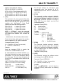
PRODUCT DESCRIPTION
400-0356-002
4
4
4
MULTI-TASKER™
APPLICATION DIAGRAM
5
DIAGRAM 1: TYPICAL CONFIGURATION
400-0356-002
5
5
MULTI-TASKER™
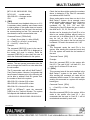
DIAGRAM 2: JUMPER SETTINGS
P7
U6
C7
R123
K1
P8
C58
C8
C13
INPUT
P9
K2
OP1
J8
C35
R65
R42
R67
R33
R36
OP3
R69
U9
OUTPUT
INPUT
OP2
C11
C1
OP4
K3
R71
OUTPUT
OUTPUT
INPUT
C40
U1
TP8
I G +5v
U23
C12
OP9
R81
C39
OP10
R104
R98
C19
OP11
C3
K6
U26
TP9
P19
R102
K7
SLAVE
C28
R66
C44
C29
C45
R117
K10
U29
C54
R70
J12
C22
C51
J10
U24
C55
C48
U12
U17
R108
C23
OP21
C43 U16
C53
R110
OP22
C50
R122
R112
R106
R119
C56
C49
C5
U28
R121
C31
C46 C47
K11
R120
K12
400-0356-002
U19
U20
U21
U31
OUTPUT
OUTPUT
OUTPUT
OUTPUT
OUTPUT
J9
J11
U14
OUTPUT
K9
U3
OP23
R124
J2-J5
ON-RS-232
OFF-IR
IR3
J3
OP24
R114
R125
IR1
J1 R72
C41 C42
SLAVE
P22
R68
MASTER
P21
C32
P20
P33
P32
MASTER
D5
IR4
J4
P24
D6
D3
IR2
J2
P25
R101
R116
R115
TP2
R103
D4
OUTPUT
P26
R118
OP19
OP20
C37
U13
OUTPUT
R97
R99
TP4
OUTPUT
P27
OP13
OP17
OP18
TP6
OUTPUT
P31
K8
INPUT
INPUT
R90
TP1
TP3
C60
OUTPUT
P30
R92
R105
R95
R93
C30
R94
OUTPUT
INPUT
C4
R107
C24
R111
R109
C25
U4
R96
OP14
OP15
C38
TP10
OUTPUT
P29
C36
R91
C14
R86
P23
U27
U5
OUTPUT
INPUT
C20
U10
R113
INPUT
P28
R88
R89
OUTPUT
INPUT
INPUT
U2
U18
Y1
R126
OUTPUT
R82
C27
OP16
1-800-ALTINEX
www.altinex.com
285-0408-002
R85
R87
OUTPUT
INPUT
INPUT
OP12
R84 U11
C52
R100
R83
P13
K5
R74
OUTPUT
P12
OP5
C16
C21
R77
R76
R73
R75
R78
OP6
INPUT
C2
R80
OP7
U7
C15
U22
OUTPUT
INPUT
P16
OP8
C18
C17
TP7
K4
R79
P17
C6
P18
I G +5v
C34
U8
J7
U30
C26
OUTPUT
U25
J5
C61
R39
P15
U15
P14
INPUT
C57
U32
6
6
IO2
OUTPUT
P10
C33
IO1
OUTPUT
INPUT
LED1
P11
C59
J6
J13
C10
INPUT
INPUT
INPUT
INPUT
INPUT
INPUT
INPUT
INPUT
INPUT
R1
R2
R3
R4
R5
R6
R7
R8
R9
R10
R11
R12
R13
R14
R15
R16
R17
R18
R19
R20
R21
R22
R23
R24
R25
R26
R27
R28
R29
R30
R31
R32
R45
R46
R47
R48
R49
R50
R51
R52
R34
R35
R37
R38
R40
R41
R43
R44
R53
R54
R55
R56
R57
R58
R59
R60
R61
R62
R63
R64
P1
D7
P2
P3
P5
P4
P29
C9
OUTPUT
P28
F1
OUTPUT
INPUT
P9
JUMPER
SETTINGS
Ports 1 to 24
P8
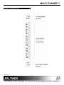
MT112-100 Input/Output Port Jumpers
Place the jumper across the two pins indicating the desired function, either Input or Output.
The diagram below shows the jumpers in the Output position. Each IO port is an individual port and
may be set to Input or Output regardless of the other ports.
OUTPUT
INPUT
IO23
P6
INPUT
IO24
MULTI-TASKER™
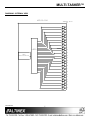
DIAGRAM 3: INTERNAL VIEW
MT112-100
TERMINAL BLOCK
I/O
I/O
CONTROL
MAIN
MICRO-PROCESSOR
400-0356-002
7
7
OC
1
OC
2
OC
3
OC
4
OC
5
OC
6
OC
7
OC
8
OC
9
OC
10
OC
11
OC
12
OC
13
OC
14
OC
15
OC
16
OC
17
OC
18
OC
19
OC
20
OC
21
OC
22
OC
23
OC
24
MULTI-TASKER™
INSTALLING YOUR MT112-100
6
1.
Step 1. Determine how each port will be used.
Either as an Input or as an Output. Set
the jumpers accordingly.
Square brackets “[
command.
2.
Use uppercase letters for all commands.
The cards in a Multi-Tasker™ system are
capable of performing various functions, as well
as providing feedback to the user or control
system. Some commands instruct a card to
perform specific actions. Other commands
request information about the status of the card.
Other commands do both at the same time.
See DIAGRAM 2 for details.
Step 2. Turn off power to the Multi-Tasker™
system.
WARNING: Installing or removing the
MT112-100 while power is
on may result in the loss of
all
stored
memory
subroutines.
A command that instructs the card to simply
perform an action will generate feedback of “[ ]”.
The open and close brackets indicate the card
received a valid command. If the command
requested information from the card, the
feedback generated by the card is the
acknowledgement of having received a valid
command.
Invalid
commands
generate
feedback of “[ERR001]”.
Step 3. Slide the MT112-100 into an available slot
in the MultiTasker™ Basic Enclosure in
order to connect to the bus. Make sure
that the MT112-100 card fits into place.
Secure the card to the MultiTasker™ by
tightening the retainer screws located on
the top and bottom of the MT112-100
card.
After processing a command, an OK or
[ERR001] will be returned as feedback if "F" is
included at the end of a command string.
Step 4. Turn on power to the Multi-Tasker™
system.
7.2 DESCRIPTION OF COMMANDS
Step 5. Connect control cables as required to the
input/output connector of the MT112-100.
Each command consists of three parts:
Function, Card ID, and Unit ID. [Function, Card
ID, Unit ID]
Step 6. Starting from the left, identify the slot
number where the MT112-100 card is
plugged into the Enclosure and note that
it is for RS-232 control.
OPERATION
Example:
[VERC3U2]
VER = Function
C3 = Card ID
U2 = Unit ID
7
7.1 RS-232 CONTROL
For detailed information regarding Function, see
each command description.
When used in the MultiTasker™ Enclosure, the
MT112-100 has many advanced remote control
capabilities, which are accessible through standard
RS-232 communication. The actual controlling can
be accomplished through a computer control
system or any other device capable of sending
RS-232 commands.
The Card ID is a unique identifier. It is equal to
the enclosure slot number, or it may be an
assigned value. As the slot number, the value
can range from 1 to 4 up to 1 to 20 depending
on the enclosure. If the value is assigned, the ID
may be a maximum of 99. Card ID 0 (C0) is
used for the controller and cannot be
reassigned.
7.1.1 RS-232 INTERFACE
The RS-232 commands for the MT112-100 are
in a simple ASCII character format.
400-0356-002
]” are part of the
8
8
MULTI-TASKER™
The Unit ID has a value from 0 to 9. Unit ID 0
should be used for single unit operation. If the
Unit ID is set to 0, then each command can be
used without Ui. Use command [SETU0] to set
Unit ID 0. See the MT100-100 User’s Guide for
more information.
[PLEASE WAIT]
Upon completion, the card will return the
following feedback:
Example:
01-08: 11111111
09-16: 11111111
17-24: 11111111
[FACTORY RESET COMPLETED]
After the reset, the status [C4] will be as follows:
[VERC3]:
for unit ID zero
[VERC3Ui]: for unit ID other than zero
[VERC3]:
equivalent to [VERC3U0]
3. [TEST]
This command performs a test of the memory
IC's on the MT112-100.
1. [C]
This command displays the status of the card.
Command Format: [TESTCnUi]
Command Format: [CnUi]
Cn = Card ID (n = # from 1 to max slots)
Ui = Unit ID (i = from 0 to 9)
Cn = Card ID (n = # from 1 to max slots)
Ui = Unit ID (i = from 0 to 9)
Example:
Example:
Perform a test of the memory on the
MT112-100 in slot #2. Send the command
[TESTC2] and observe the following feedback:
There is an MT112-100 card is in slot #4. All I/O
ports are ON. Send the command [C4], and the
system will return the following feedback:
MEMORY IC TEST RESULTS
01-08: 11111111
09-16: 11111111
17-24: 11111111
U14 OK
U19 OK
U20 OK
U21 OK
U31 OK
U32 OK
The feedback provides the current state of the
MT112-100. The IO Status shows all 1's, or ON.
2. [CLR]
This command performs a reset of the card and
restores settings to the factory defaults. The
subroutines stored in memory are not affected
by this command. In order to clear the
subroutine memory, see the [CLRS] command.
4. [?]
This command will return general information
about the Multi-Tasker™ and cards installed in
the unit.
Command Format: [CLRCnUi]
Command Format: [?Ui]
Cn = Card ID (n = # from 1 to max slots)
Ui = Unit ID (i = from 0 to 9)
Ui = Unit ID (i = from 0 to 9)
Example:
Example:
A Multi-Tasker™ with Unit ID #1 has a
panel with part number MT101-101
contains an MT103-122, MT103-123
MT112-100. Send the command [?U1]
receive the following feedback:
Send the command [CLRC4] to reset the card in
slot #4 to factory defaults. After sending the
command the feedback will be as follows:
400-0356-002
9
9
front
and
and
and
MULTI-TASKER™
[(MT101-101U1)(MT103-122C01)
(MT103-123C02)(MT112-100C03)]
The I/O port settings are read left to right
representing ports one through 24. A “0”
indicates the port is low and a “1” indicates the
port is high.
MT101-101U1 = Panel Number and Unit ID
MT103-122C01 = An MT103-122 is in slot 1
MT103-123C02 = An MT103-123 is in slot 2
MT112-100C03 = An MT112-100 is in slot 3
6. [STA1]
This command enables automatic feedback
from the front panel. The command affects any
card with auto-feedback capability, not just the
MT112-100. The default at power on or reset is
STA0, OFF. For more details, see the [?Cn]
command definition.
5. [?Cn]
This command will return general information
about the card and its status. It is a function of
both the card and the front panel and is only
available with Multi-Tasker™ Front Panel
systems that have the following firmware:
690-0122-015
690-0123-004
690-0124-018
Command Format [STA1]
= Version 015 or later.
= Version 004 or later.
= Version 018 or later.
MT
VR
IO
NOTE: In MTSetup™, send the command
[VER] from the Terminal Window. The system
will respond with feedback that includes the
following:
Model Number
Firmware Revision
IO Port Status
Example:
Command =
Feedback =
690-0122-015 690-0123-004 690-0124-018
Check the last three digits against the numbers
above to determine if the option is available.
Command Format: [?CnUi]
[WRIO1=0C4]
(IO0111…1111C02)
IO
= IO Status
011… = Port 1=Low
Port 2=High
Port 3=High etc…
C04 = Card/Slot number
7. [STA0]
Cn = Card ID (n = # from 1 to max slots)
Ui = Unit ID (i = from 0 to 9)
This command disables automatic feedback
from the card and front panel. The command
affects any card with auto-feedback capability,
not just the MT112-100. The default at power on
or reset is STA0, OFF.
Example:
Send the command [?C4] to receive the
feedback for the MT112-100 in slot #4:
Command Format [STA0]
All status feedback is enclosed in brackets, “[ ]“.
Each data field within the status is enclosed in
parentheses. The first two characters identify
the status type. The last three characters are
the card’s ID. The feedback will be similar to the
following:
8. [VER]
This command receives the software version
and card type for the MT112-100 card.
Command Format: [VERCnUi]
[(MT112-100C04)(VR690-0185-003C04)
(ON111111111111111111111111C04)]
Cn = Card ID (n = # from 1 to max slots)
Ui = Unit ID (i = # from 0 to 9)
MT112-100
VR690-0185-001
ON1111…
Example:
400-0356-002
= model number
= firmware version
= IO Port Status (1-24)
There is an MT112-100 in slot #4. Send the
command [VERC4] and receive the following
feedback:
10
10
MULTI-TASKER™
[MT112-100 690-0185-003 C04]
Check the last three digits against the numbers
above to determine if the Card ID commands
can address all 99 Card ID's.
MT112-100
= model number
690-0185-003 = firmware version
C04
= card ID
Some cards require more than one slot in the
Multi-Tasker™ system. As an example, some
matrix switcher cards require 4 slots. If there are
5 of these cards installed, they would be
numbered C4, C8, C12, C16 and C20.
Changing the Card ID allows the user to define
the cards as C1, C2, C3, C4 and C5.
9. [FBD]
This command turns feedback delay on or off. It
is necessary when installing some newer cards
in older systems. If the system does not receive
all of the feedback from the card, the card may
be communicating too fast. This command will
slow down the card's communication rate.
Another use for changing the Card ID is to be
able to use multiple systems without having to
set each unit to a different Unit ID. All systems
may be left as Unit ID 0 for ease of
programming. The cards in the first unit may be
numbered 1-10 and in the second unit 11-20.
Command Format: [FBDmCnUi]
m = Delay (0= no delay, 1= delay 100mS)
Cn = Card ID (n = # from 1 to max slots)
Ui = Unit ID (i = from 0 to 9)
10. [RSI]
Example:
This command resets the card ID's in the
system. After sending this command, each card
ID in the system will match the slot number of
the card.
The command [HELPC4] is sent to the card in
slot #4. Some of the HELP file is displayed on
the screen, but most is missing. Send the
command [FBD1C4] to slow down the rate at
which the card sends feedback to the system.
Command Format: [RSI]
CARD ID COMMANDS
Example:
The default Card ID is the same as the card slot
number. The next several commands allow the
user to change the Card ID to a value other than
the slot number.
Send the command [RSI] to the system with
Unit ID 0. The card in slot 1 will have ID 1, the
card in slot 2 will have ID 2 and so on.
11. [SIDn]
The ID commands work with all Multi-Tasker™
Front Panel systems. However, front panels that
have firmware releases prior to the following will
not be able to address Card ID's greater than
the number of slots in the system:
690-0122-019 = Version 019 or later.
This command sets all the cards installed in the
Multi-Tasker™ system to the same Card ID.
After sending this command, all cards will be
addressed with the same ID. Use caution when
sending this command to a system with multiple
board types.
690-0123-005 = Version 005 or later.
Command Format: [SIDn]
690-0124-019 = Version 019 or later.
n
NOTE: In MTSetup™, send the command
[VER] from the Terminal Window. The system
will respond with feedback which includes:
Example:
Send the command [SID1] to the system. All the
cards in the system now have ID 1. Any
commands that are sent to Card ID 1 will be
received and executed by each card.
690-0122-015 690-0123-005 690-0124-019
400-0356-002
= Card ID (n = # from 1 to 99)
11
11
MULTI-TASKER™
12. [SIDnCi]
14. [RSN]
This command sets the Card ID of a single card
to a number from 1 to 99.
This command reads the slot number of the
card with a specified ID number, and returns the
value to the system to be displayed in the
terminal window. If more than one card has the
same ID, each slot number will be displayed.
Command Format: [SIDnCi]
n = Card ID (n = # from 1 to 99)
Ci = Slot Number (i = # from 1 to max slots)
Command Format: [RSNCi]
Example:
Ci = Card ID (i = # from 1 to 99)
Send the command [SID50C10] to set the ID of
the card in slot #10 to an ID of 50.
Example:
The card in slot #4 takes up four slots in the
enclosure. Its ID was set to 1 since it is the first
card installed in the system, reading from left to
right. Send the command [RSNC1] to find the
slot number of this card. The system responds
with the following feedback:
13. [SID+n]
This command sets the Card ID of all the cards
in a system to their slot number plus the offset
value.
Command Format: [SID+n]
[4]
n = Offset amount (n = # from 0 to 99)
The maximum Card ID is 99, so subtract
the highest slot number from 99 to find
the maximum offset. For example, in an 8
slot enclosure, the maximum offset would
be 91. The slot number, 8, plus the offset,
91, equals 99.
15. [WAIT]
This command causes the control to delay
processing commands for a defined interval.
Command Format: [WAITmCnUi]
m = Multiples of 0.1sec (m = 01 to 99)
Cn = Card ID (n = # from 1 to max slots)
Ui = Unit ID (i = from 0 to 9)
Example:
There are two, 20 slot enclosures to be
connected together during normal operation.
The first unit will use the Card ID defaults which
are equal to their slot numbers. The second unit
will have the same Unit ID, but will have the
card ID's offset by 20.
Example:
Many commands are begin sent to the card in
slot #4. Delay 0.3 seconds after issuing several
commands, and then continue with issuing more
commands. Send the command [WAIT03C4].
Connect the computer to the second unit only
and send the command [SID+20] to set the ID
of all the cards in the enclosure to their slot
number plus 20. Reconnect both units to the
computer.
16. [RDIO]
This command reads and displays the status of
the I/O ports. Each port status is a "1" or a "0".
The port displayed on the left is Port 1 and Port
24 is on the right.
The cards in the first unit will be referenced as
Card ID's 1-20 and the cards in the second unit
will be referenced by Card ID's 21-40.
0
1
= Port is OFF
= Port is ON
Command Format: [RDIOkCnUi]
k = I/O port number (1 to 24, or * for all)
Cn = Card ID (n = # from 1 to max slots)
Ui = Unit ID (i = # from 0 to 9)
400-0356-002
12
12
MULTI-TASKER™
Example 1:
18. [WRI]
There is an MT112-100 in slot #2. I/O port
number "4" is ON. Send the command
[RDIO4C2] and the system will return the
following feedback:
This command assigns a subroutine to perform
when there is a transition on an I/O port.
Command Format: [WRIx,y=SUBkCnUi]
x
y
= I/O Port (x = # from 1 to 24)
= Port Transition (y= 0 or y=1)
0 = Low to High transition
1 = High to Low transition
k = Subroutine (k = # from 1 to 180)
Cn = Card ID (n = # from 1 to max slots)
Ui = Unit ID (i = from 0 to 9)
1
A "1" indicates the control is on. A "0" would
indicate the control was off.
Example 2:
There is an MT112-100 in slot #3. I/O Controls 1
and 2 are off while 3-24 are on. Send the
command [RDIO*C3] and receive the following
feedback:
Example:
An MT112-100 is in slot #3. Send the command
[WRI2,1=SUB9C3] to assign subroutine 9 to be
performed when I/O Port #2 changes from a
High to a Low.
001111111111111111111111
The ports are displayed left to right. The left
most digit represents Port 1 and the rightmost
represents Port 24. The first two 0's indicate
Ports 1 and 2 are off. The remaining 1's
indicate Ports 3-24 are on.
19. [RDIS]
This command displays
associated with an IO port.
the
subroutine
Command Format: [RDISxCnUi]
17. [WRIO]
This command writes to a single I/O port or all
the I/O ports and sets the output high or low. All
ports must be set to the same state using this
command.
x = I/O Port (x = # from 1 to 24)
Cn = Card ID (n = # from 1 to max slots)
Ui = Unit ID (i = from 0 to 9)
Command Format: [WRIOk=xCnUi]
An MT112-100 is in slot #3. Send the command
[RDIS2C3] and receive the following feedback:
k
x
=
=
Cn =
Ui =
Example:
Port Number (1 to 24, * for all)
I/O state to set port
0 = Set I/O port low (GND)
1 = Set I/O port high (+5V@24ma)
Card ID (n = # from 1 to max slots)
Unit ID (i = from 0 to 9)
Port02: Sub008, Sub009.
Port 02 is the port queried. Sub008 is the
subroutine performed when there is a LOW to
HIGH transition and Sub009 is performed when
there is a HIGH to LOW transition on port 2.
Example 1:
20. [RDIS*]
Set I/O #1 on for card in slot #1 by sending the
command [WRIO1=1C1].
This command displays the
associated with all the IO ports.
Example 2:
Command Format: [RDIS*CnUi]
Set all I/Os off for the card in slot #1 by sending
the command [WRIO * =0C1].
400-0356-002
subroutines
Cn = Card ID (n = # from 1 to max slots)
Ui = Unit ID (i = from 0 to 9)
13
13
MULTI-TASKER™
Example:
The ports are designed to work in pairs. Port 1
handles external Key #1 and Port 2 handles
external LED #1. Port 3 handles external Key #2
and Port 4 handles external LED #2.
An MT112-100 located in slot #3. Send the
command [RDIS*C3] and receive feedback
similar to the following:
In this setup, the Port 1 jumper should be set to
the INPUT position. Port 2's jumper should be in
the OUTPUT position and so on.
Port01: Sub000, Sub001.
Port02: Sub008, Sub009.
…
Port24: Sub001, Sub020.
Command Format: [WRKEYx,y=SUBkCnUi]
x
y
k
Cn
Ui
21. [CLRI]
This command clears the subroutines assigned
to an IO port.
Command Format: [CLRIxCnUi]
= key number
= LED state (0= ON, 1= OFF)
= subroutine number (# from 1 to 180)
= Card ID (n = # from 1 to max slots)
= Unit ID (i = from 0 to 9)
x = I/O Port (x = # from 1 to 24)
Cn = Card ID (n = # from 1 to max slots)
Ui = Unit ID (i = from 0 to 9)
Example:
Example:
I/O#1 = KEY#1 Port 1 jumpered for INPUT
I/O#2 = LED#1 Port 2 jumpered for OUTPUT
The external keys (switches) and LED's are
wired to the I/O ports as follows:
In order to clear the subroutines for IO port 8 of
card 2, send the command [CLRI8C2].
I/O#3 = KEY#2 Port 3 jumpered for INPUT
I/O#4 = LED#2 Port 4 jumpered for OUTPUT
22. [CLRI*]
This command clears all subroutines associated
with all IO ports for a given card.
Assign subroutine 10 to be executed if external
Key #1 is pressed and external LED #1 is ON.
Command Format: [CLRI*CnUi]
[WRKEY1,0=SUB10C4]
x = I/O Port (x = # from 1 to 24)
Cn = Card ID (n = # from 1 to max slots)
Ui = Unit ID (i = from 0 to 9)
The system knows external LED#1 (Port 2) is on
since the command [WRIO2=1C4] must have
been issued. Port 2 was turned on to drive the
LED.
Example:
24. [WRS]
Clear all of the subroutines for all IO ports on
card 2 by sending the command [CLRI*C2].
This command writes/programs a subroutine in
the MT112-100 by adding functions to its
subroutine. The subroutines may be used to
control other cards in the Multi-Tasker™
system, but cannot be used to control the Front
Panel LED's.
23. [WRKEY]
This command allows external switches and
LED's to control or be controlled through the I/O
ports. Subroutines are assigned to be executed
when an external key (switch) is pressed and
the external LED is in a given state.
See the MT101-110 User Guide for complete
instructions.
CAUTION: Do NOT confuse this command with
the {WRS} command, which writes subroutines
to the Front Panel memory.
400-0356-002
14
14
MULTI-TASKER™
Command Format: [WRSm=F1,F2,…;CnUi]
Example 1:
Sm
= Subroutine ID (m = # from 1 to 180)
F1,F2… = Functions:
functions
must
be
separated by a comma.
Read back the subroutine in the previous
example for the WRS command. The card is in
slot #4 and the Subroutine is 2. Send the
command [RDS2C4] and receive the following
feedback:
Cn
Ui
= Card ID (n = # from 1 to max slots)
= Unit ID (i = from 0 to 9)
ON1C3, ON2C3, ON123456C7, ONC3, ON4C3
The maximum number of characters, including
commas, which may be sent to a subroutine in a
single command is 16. If the length of the
command string exceeds the maximum, break
the functions into smaller groups. Previous
commands are NOT overwritten. The subroutine
is appended with the new commands.
Example 2:
Read back the contents of an empty subroutine.
The card is in slot #4 and the subroutine is
Subroutine 9. Send the command [RDS9C4]
and receive the following feedback:
Subroutine Empty
Example:
26. [CLRS]
Program Subroutine 2 of the card in slot #4 with
the following functions: ON1C3, ON2C3 and
ON123456C7.
Send
the
command
[WRS2=ON1C3,ON2C3,ON123456C7;C4].
NOTE:
This command clears the contents of memory
for one or all subroutines.
Command Format: [CLRSmCnUi]
A comma must be used between
functions.
Sm = Subroutine (m = # from 1 to 180, * = all)
Cn = Card ID (n = # from 1 to max slots)
Ui = Unit ID (i = from 0 to 9)
Add more functions such as ON3C3 and
ON4C3 to the subroutine. Subroutines are
written accumulatively. That is, each command
is appended to the functions that are already
part of the subroutine. Therefore, to add the
functions ON3C3 and ON4C3, it is only
necessary
to
send
the
command
[WRS2=ON3C3, ON4C3;C4].
Example 1: Clear One
Clear Subroutine 2 of the card in slot #4. Send
the command [CLRS2C4] and observe the
following feedback:
Sub Clear
Example 2: Clear ALL
After sending the command above, the contents
of Subroutine 2 will contain the following:
Clear all subroutines of the card in slot #4. Send
the command [CLRS*C4] and observe the
following feedback:
ON1C3, ON2C3, ON123456C7,ONC3, ON4C3
25. [RDS]
ALL SUBS WILL BE CLEARED
PLEASE WAIT
This command reads and displays the functions
programmed in a subroutine.
When all subroutines have been cleared, the
following feedback will be displayed:
Command Format: [RDSmCnUi]
TASK COMPLETED
Sm = Subroutine (m = # from 1 to 180)
Cn = Card ID (n = # from 1 to max slots)
Ui = Unit ID (i = from 0 to 9)
400-0356-002
27. [SUB]
This command executes the functions stored in
a subroutine.
15
15
MULTI-TASKER™
These subroutines are stored directly on the
card and are separate from the commands
stored in the Front Panel. Therefore, the front
panel LED's cannot be controlled with
commands stored on the control card, but they
may be used to control other cards.
In Multi-Tasker™ systems with audio and video
cards, boards are typically grouped as follows:
Group 1 = Video Cards
Group 2 = Audio Cards
Group 3 = Video and Audio Cards
Command Format: [WRCn1Cn2…GkUi]
Command Format: [SUBmCnUi]
Cn = Card ID (n = slot # from 1 to max slots)
Gk = Group number (k = # from 1-8)
Ui = Unit ID (i = # from 0-9)
m = Subroutine (m = # from 1 to 180)
Cn = Card ID (n = # from 1 to max slots)
Ui = Unit ID (i = from 0 to 9)
Example:
Example:
Group cards 2, 4, and 6 as group 5 of Unit ID 1
by sending the command [WRC2C4C6G5U1].
After executing this command, cards 2, 4 and 6
will be grouped together as group 5 of Unit ID 1.
The system will return the following feedback:
The function ON1C3 is stored in Subroutine 55
of the card ID 1. Send the command [SUB55C1]
and the stored function will be executed. Output
1 of card 3 will now be turned on.
28. [HELP]
[G5=C2C4C6]
This command displays information available for
the Multi-Tasker interface commands.
Now, when a command is sent to G5, each
board in G5 will execute the same command.
Command Format: [HELPCnUi]
30. [RMC]
Cn = Card ID (n = # from 1 to max slots)
Ui = Unit ID (i = # from 0 to 9)
This command may be used to remove one or
more group members from a group. Reset the
system after using this command for all changes
to take effect.
Example:
In order to view the RS-232 commands
available for the MT112-100 card in slot #2,
send the command [HELPC2]. The commands,
along with a brief description, will be displayed
in the Terminal Window.
Command Format: [RMCn1Cn2…GkUi]
Cn = Card ID (n= # from 1 to max slots)
Gk = Group number (k = # from 1-8)
Ui = Unit ID (i = # from 0-9)
GROUP COMMANDS
Example:
The next commands are group commands. These
commands are not normally used with control
cards, but are provided as added information for
controlling other cards in the system.
Group 5 consists of the cards located in slots
numbered 2, 4, and 6. Remove just cards #4
and #6 from the group by sending the command
[RMC4C6G1]. The system will return the
following feedback:
29. [WR]
[G5=C2]
This command groups multiple cards in the
enclosure allowing all the group members to be
controlled simultaneously with the same
command. Each unit may define a maximum of
eight groups.
31. [RMG]
This command may be used to delete an entire
group, or all groups.
REMOVE A GROUP
Remove all the members from the group,
effectively deleting the group.
400-0356-002
16
16
MULTI-TASKER™
Command Format: [RMGkUi]
33. [CLRG]
Gk = Group number (k = # from 1-8)
This command clears the members for a single
group or for all groups. The clear command
restores the cards to default settings and is the
equivalent to sending the [CLR] command to
each individual card.
Ui = Unit ID (i = # from 0-9)
Example:
Group 5 consists of the cards located in slots
number 2, 4 and 6. Remove all cards from the
group by sending the command [RMG5]. The
system will return the following feedback:
[G5=0]
NOTE: Since this command is sending the
[CLR] command to its group members,
each card will display its own reset
message, if any.
REMOVE ALL GROUPS
Command Format: [CLRGkUi]
Remove all the members from every group,
effectively deleting all groups.
Gk = Group ID (k = # from 1-8, or * for all)
Command Format: [RMG*Ui]
Example:
Ui = Unit ID (i = # from 0-9)
1)
To clear group 1 of Unit ID 0, send the
[CLRG1] command. This command clears
the members for the specified group only.
2)
To clear all groups of Unit ID 1, send the
[CLRG*U1] command.
Ui = Unit ID (i = # from 0-9)
Example:
Group 5 consists of cards 2, 4 and 6. Group 2
consists of cards 1, 2, 3, 4 and 5. Delete all the
groups by sending the command [RMG*]. The
system will return the following feedback:
34. [CLM]
G1-G8:EMPTY
This command removes the members in a
group and leaves the group empty.
32. [RD]
This command reads and then displays the
members in each group.
Command Format: [CLMGkUi]
Command Format: [RDGkUi]
Ui = Unit ID (i = # from 0-9)
Gk = Group number (k = # from 1-8)
Example:
Ui = Unit ID (i = # from 0-9)
Group 5 of Unit ID 1 contains the cards in slots
2, 4 and 6. Read the member data for group 5
of Unit ID 1. Send the command [RDG5U1] and
receive the following feedback:
Gk = Group number (k = # from 1-8)
Example:
The cards in slots 2, 4 and 6 are part of
group 5. Read the member data for group 5, by
sending the command [RDG5]. The system will
return feedback as follows:
[G5=C2C4C6]
[G5=C2C4C6]
Now, clear group 5 by sending the command
[CLMG5U1]. Reread the member data as above
and note the following feedback:
The feedback shows G5 (Group 5) and then the
cards that make up Group 5. In this case,
Group 1 includes C2, C4 and C6.
[G5=0]
400-0356-002
17
17
MULTI-TASKER™
7.3 SUMMARY of COMMANDS
24) [WRS]
Write a subroutine
Card Commands
25) [RDS]
Read a subroutine
1)
[C]
Receives card status.
26) [CLRS]
Clear a subroutine
2)
[CLR]
Resets card to default values.
27) [SUB]
3)
[TEST]
Tests the memory IC's.
Execute the functions in a
subroutine.
4)
[?]
Request system information
28) [HELP]
Display available commands
for the MT112-100.
5)
[?Cn]
Request card information
6)
[STA1]
Enable auto feedback.
7)
[STA0]
Disable auto feedback.
8)
[VER]
Receives software version.
9)
[FBD]
Feedback delay on/off
10) [RSI]
Reset Card ID’s
11) [SIDn]
Set all Card ID’s
12) [SIDnCi]
Set one Card ID
13) [SID+n]
Set Card ID offset
14) [RSN]
Read Card slot number
15) [WAIT]
Tells controller to delay before
the next instruction.
16) [RDIO]
Display I/O port status.
17) [WRIO]
Set one or more I/O ports to
different states.
Assigns subroutine to an I/O
port state change.
19) [RDIS]
Display
the
subroutines
associated with an IO port
20) [RDIS*]
Display
the
subroutines
associated with all IO ports
21) [CLRI]
Clear
the
subroutines
associated with an IO port
22) [CLRI*]
Clear all the subroutines
associated with a IO ports
400-0356-002
29) [WR]
Groups multiple cards
30) [RMC]
Remove members from group
31) [RMG]
Delete group
32) [RD]
Displays group members
33) [CLRG]
Clears group members
34) [CLM]
Delete group
7.4 MENU MODE
18) [WRI]
23) [WRKEY] Program external
and LED's.
Group Commands
MENU MODE commands are RS-232 commands
that allow the same functionality as the
programming commands. Unlike the programming
commands in the previous sections, 7.2 and 7.3,
MENU commands prompt the user to select from a
list of available commands. The system then
responds based upon selections made by the user.
MENU commands may be issued in response to
prompts from within MTSetup™ or any other
RS-232 communication software.
The MENU driven commands are only available
with Multi-Tasker™ Front Panel systems that have
the following firmware:
690-0122-015 = Version 015 or later.
690-0123-004 = Version 004 or later.
690-0124-018 = Version 018 or later.
NOTE: In MTSetup™, send the command [VER]
from the Terminal Window. The system will
respond with feedback including the following:
switches
690-0122-015 690-0123-004 690-0124-018
Check the last three digits against the numbers
above to determine if the MENU MODE option is
available.
18
18
MULTI-TASKER™
WARNING: Do NOT enter any characters
except the one relating to the desired
menu. Pressing ENTER or RETURN after
"8" will force the system back to the original
prompt.
7.4.1 MENU COMMAND DEFINITIONS
Refer to section 7.2 for details on card functions
and examples.
SUGGESTION: Before using the menu mode,
it is best to disable the
automatic feedback feature.
The values and current
settings will be displayed in
the menu mode, but the
automatic feature will display
after each setting change
making the menus difficult to
read.
7.
After selecting the MT112-100 as described
above, the system will prompt for selections
specific to that card.
8.
Read each menu carefully, and continue
selecting keys as prompted for further
functions.
7.4.3 MENU TYPES
1.
7.4.2 USING MENU MODE
MAIN MENU
The first menu displayed after selecting the
card is the Main Menu. This menu provides
access to the main functions related to the
card. Press the key representing the menu
item to access. A sub menu will appear
next.
1.
In order to enter MENU mode, the system
needs to be connected to a computer
running MTSetup™ or other RS-232 control
software.
2.
Insert the card into an empty slot and push
in all the way for a secure fit.
3.
Reset the system or power the system OFF
and then ON.
4.
In MTSetup™, click the cursor in the
Terminal Window and press the ENTER
key.
Each sub menu will either display another
menu (sub menu) or a list of available
options or settings. Press the key
corresponding to the menu choice to
change a setting or select the next menu.
5.
The system will interrogate the enclosure
and return a list cards installed and their
slot locations.
NOTE: Pressing the ESCAPE (ESC) key in
any menu will take you up to the previous
menu.
2.
Example: 8 (Slot 8): MT112-100
7.4.4 MT112-100 MENUS
NOTE: Only cards supporting the MENU
feature will be displayed.
5.
6.
Following are the menus available to the
MT112-100. The first menu is the Main Menu
only. The second listing is an expansion of all
the menu items available.
Find
the
alpha-numeric
character
representing the card whose setup requires
changing. It will be the first character in the
line.
The expanded menu contains values in
parentheses that indicate the current setting or
value of that parameter. Some menu settings
act as toggle features. For example, port
controls only provide one option. If the port is
on, it may be turned off. If the port is off, it may
be turned on.
Press the number or letter associated with
the card, and a menu with options available
for that card will appear on the screen. In
the example above, press "8".
400-0356-002
SUB MENUS
19
19
MULTI-TASKER™
MT112-100 MAIN MENU
KEY Comments
05
Select MT112-100 in slot #5
1
Select Control Menu and receive the
following feedback:
1: CONTROL
2: VERSION
3: STATUS
Press Key to Toggle Ports
4: HELP
1:1 (1)
2:2 (1)
3:3 (1)
4:4 (1)
5:5 (1)
6:6 (1)
7:7 (1)
8:8 (1)
ESC: GO BACK
MT112-100 EXPANDED MENUS
1. CONTROL
Press Key to Toggle Ports
1:1 (1)
2:2 (1)
3:3 (1)
4:4 (1)
5:5 (1)
6:6 (1)
7:7 (1)
8:8 (1)
9:9 (1)
A:10 (1)
B:11 (1)
C:12 (1)
D:13 (1)
E:14 (1)
F:15 (1)
G:16 (1)
H:17 (1)
I:18 (1)
J:19 (1)
K:20 (1)
L:21 (1)
M:22 (1)
N:23 (1)
O:24 (1)
3.
4.
5.
If the value in parentheses for port
number 20 is 1, then the port is ON. Press
'K' to toggle the port OFF.
20
Toggle Relay Number 20
The system will return feedback indicating
the port is now OFF.
ESC Return to the Main Menu
VERSION
Returns card number and firmware version.
STATUS
Equivalent to the [C] command.
Returns the card status/relay states.
HELP
Equivalent to the [HELP] command.
Displays a list of commands available for
the MT112-100 along with a brief
description.
ESC
Returns to the parent menu.
2. All Ports ON
An MT112-100 is in slot #5. Turn ON all IO
Ports regardless of whether they are ON or
OFF. Press ENTER for a list of available cards.
KEY
05
1
99
Comments
Select MT112-100 in slot #5
Select Control Menu
Turn ON all ports.
The system will return feedback indicating
all ports are now ON.
ESC Return to the Main Menu
3. Display Card Status
7.4.5 MENU MODE EXAMPLES
Display the status of the MT112-100 in slot #19.
Starting from the MT112-100's Main Menu,
follow the keystrokes below:
1. Turn ON IO Port 20
An MT112-100 is in slot #5. All IO Ports are
currently ON. Turn OFF IO Port number 20.
Start by clicking the mouse in the Terminal
window and pressing the ENTER key. The
system will return a list of available cards with
Menu Mode features:
400-0356-002
H:17 (1)
I:18 (1)
J:19 (1)
K:20 (1)
L:21 (1)
M:22 (1)
N:23 (1)
O:24 (1)
P: All ON(1) Q: All OFF(0) ESC: GO
BACK
P: All ON(1) Q: All OFF(0) ESC: GO
BACK
2.
9:9 (1)
A:10 (1)
B:11 (1)
C:12 (1)
D:13 (1)
E:14 (1)
F:15 (1)
G:16 (1)
3
Displays card status
NOTE: In this case, the Main Menu is still
active although it is not redisplayed.
20
20
MULTI-TASKER™
TROUBLESHOOTING GUIDE
8
ALTINEX POLICY
We have carefully tested and have found no
problems in the supplied MT112-100; however, we
would like to offer suggestions for the following:
9.1 LIMITED WARRANTY/RETURN POLICY
Please
see
the
Altinex
website
at
www.altinex.com for details on warranty and
return policy.
8.1 I/O PORT NON RESPONSIVE
Cause 1:
9.2 CONTACT INFORMATION
Jumpers are not set.
ALTINEX, INC
Solution 1: The I/O ports may be used as input
or output ports. Verify the jumpers
are set to the correct position.
592 Apollo Street
Brea, CA 92821 USA
Solution 2: Check the cable and verify there is
continuity for both the I/O port pin
and the Ground pin. If there is still
no response, please call Altinex at
(714) 990-2300.
TEL: 714 990-2300
TOLL FREE: 1-800-ALTINEX
WEB: www.altinex.com
E-MAIL: [email protected]
400-0356-002
9
21
21