1
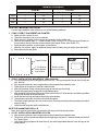
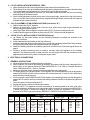
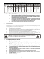
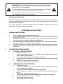
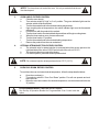
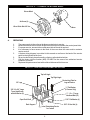
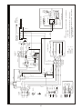
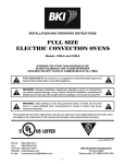
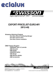
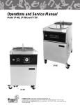
INSTALLATION AND OPERATING INSTRUCTIONS
FULL SIZE (CO1-E) & 1/2 SIZE (COH-E)
ELECTRIC CONVECTION OVENS
Models: CO1-E and COH-E
INTENDED FOR OTHER THAN HOUSEHOLD USE
RETAIN THIS MANUAL FOR FUTURE REFERENCE
OVEN MUST BE KEPT CLEAR OF COMBUSTIBLES AT ALL TIMES
FOR YOUR SAFETY
!
Do not store or use gasoline or other flammable vapors and liquids in the vicinity
of this or any other appliance.
!
!
Improper installation, adjustment, alteration, service or maintenance can cause
property damage, injury or death. Read the Installation, Operating and
Maintenance Instructions thoroughly before installing or servicing this equipment.
!
!
Initial heating of oven may generate smoke or fumes and must be done in a wellventilated area. Overexposure to smoke or fumes may cause nausea or dizziness.
!
WARNING
This equipment has been engineered to provide you with year round dependable service when used
according to the instructions in this manual and standard commercial kitchen practices.
P/N U4149A 9/07
Phone:
Fax:
Toll Free:
Website:
E-mail:
(864) 963-3471
(864) 963-5316
(800) 927-6887
www.bkideas.com
[email protected]
BKI Worldwide Headquarters
PO Box 80400
Simpsonville, SC 29680-0400 USA
1
INDEX
INSTALLATION INSTRUCTIONS
SECTION
1
2
3A
3B
4
5
6
7
ITEM
PAGE
Receiving
Location & Minimum Clearances
Set-Up & Mounting for COH-E1
Set-up & Mounting for CO1-E
Electrical Connections
Initial Start Up
System Check & Rotary Controls
Steam Injection (Optional)
2
2
3
3
4
5
5
6
OPERATING INSTRUCTIONS
SECTION
1
2
3
4
5
6
7
ITEM
PAGE
General Instructions
System Operation Sequence
1. Cook Only
2. Timed Cooking
3. Cook & Hold
4. Steam Injection (Optional)
5. Oven Cool Down
Cleaning
Servicing
Wiring Diagrams
a. 208-240V North America
b. 230-400V CE
Parts Lists w/Exploded Views
a. CO1-E Parts List w/Exploded View
b. COH-E Parts List w/Exploded View
Warranty
6
6
6
6
7
7
7
8
9
10
10
11
12
12
15
19
INSTALLATION INSTRUCTIONS
1. RECEIVING
Read the notice on the outside carton regarding damage in transit. “CONCEALED DAMAGE”,
damage discovered after opening the crate(s), must be reported immediately to the carrier. The carrier
will perform an inspection of the damage and furnish forms for the consignee's claim against the carrier.
Retain all packing material - including outer carton until the inspection has been completed. When the
oven arrives, it should consist of: A crate (or carton) containing your new oven, and a carton containing
four 30” legs with mounting hardware (for CO1-E1 oven only) or a set of four 6” legs (for CO1-E2
stacked installations). Legs for COH-E are packed inside the oven.
2. LOCATION & MINIMUM CLEARANCES
a. Adequate air space must be provided for proper venting of the motor and the controls.
b. The oven should be located no closer than 1” (COH-E) / 2” (CO1-E) on the left side, 1” on the right
side and 1” on the rear from any combustible or non-combustible construction.
c. Keep the area around your oven free and clear of combustible materials.
d. Provision of adequate air supply to the oven for ventilation is essential. Minimum clearances must
be maintained at all times.
2
MINIMUM CLEARANCES
COH-E1
CO1-E1
Inches
mm
Inches
mm
Right
1
25
1
25
Left
1
25
2
50
Rear
1
25
1
25
Suitable for installation on combustible floors when installed on factory supplied legs or casters.
3A.SET-UP / MOUNTING FOR COH-E1
Counter-top installation must conform to one of the following methods:
1. COH-E1: DIRECT PLACEMENT ON COUNTER
a. Make sure the counter is level.
b. Clean the area where unit is to be installed.
c. Place the unit in position on the counter and mark the outline of the unit.
d. Remove the unit and apply 1 ¼” bead of sealer (Dow Corning RTV 732 Multipurpose Sealant or
its equivalent) directly onto the counter following the traced outline (see Sketch “A”).
e. Place the unit in position, over the sealer, on the counter.
f. With the unit in place, apply an additional heavy bead of sealer along all edges (see Sketch“B”).
g. Wipe clean any excess sealer.
SKETCH “A” - TOP VIEW
SKETCH “B” - FRONT VIEW
RLDWIDEPRIDE
BKI WO
BAKERS
Traced Outline
Bead of sealer
along oven edges
1 1/4” Bead of
sealer applied
onto counter
2. COH-E1: INSTALLATION / MOUNTING 6” LEGS (Optional)
a. The adjustable legs are not shipped mounted to unit. The legs are packed inside the unit with the
wire shelves.
b. After unpacking the unit, remove legs and any other material from inside the oven.
c. Place the unit on a counter or other flat, stable surface.
d. With sufficient help, tilt the unit back far enough to mount the two front legs.
e. Tighten the upper part of the leg with an adjustable wrench.
f. After installing the front legs, lift the rear of the unit more than 6” off the surface and block in position
using wood or some other solid material.
g. Mount the two rear legs and tighten them in the same fashion.
h. Using proper equipment, move the unit to its final location.
i. To ensure proper operation, the unit must be level. Each leg can be adjusted separately to achieve
proper leveling.
j. Install the shelf supports and the wire shelves.
3B SET-UP / MOUNTING FOR CO1-E
Note: Units must be leveled after leg installation. Each leg is individually adjustable.
1. CO1-E1: INSTALLATION / MOUNTING 30” LEGS
a. After unpacking the unit, remove legs and any other material from inside the oven.
b. Tilt the oven onto its left side and attach the two right legs using three ½” bolts and washers for each
leg. Tighten firmly.
c. Use proper lifting equipment to raise the unit, and while suspended attach the two left legs in the
same manner.
3
2. CO1-E2: INSTALLATION / MOUNTING 6” LEGS
a. After unpacking the unit, remove legs and any other material from inside the oven.
b. Tilt the bottom oven onto its left side and attach the two mounting plates to the right underside using
½” bolts and washers and tighten firmly. Screw the 6” legs into the center holes.
c. Use proper lifting equipment to raise the unit, and while suspended attach the two left mounting
plates and legs in the same manner.
d. Use the lifting equipment to raise the top oven to the proper height, and slide it on top of the bottom
oven. Line up the sides and front and use the supplied stacking brackets, screws and lock washers
to fasten the two ovens in the back.
3.
CO1-E1: ASSEMBLY OF AN OPEN RACK STAND (see Sketch “D”)
a. Slightly loosen the (12) 30” leg bolts.
b. Remove (4) inner bolts, (1) from each of the four legs, place the top right angle underneath as
shown, and tighten these (4) bolts.
c. Insert Open Rack Shelf and tighten into place with (8) 3/8”-16 screws, washers and nuts.
d. Position Rack Supports and tighten in place using (4) 5/16”-18 hex nuts and flat washers.
4.
COH-E / CO1-E1: INSTALLATION OF CASTERS (Optional)
a. (4) Casters (2) with wheel brakes and the mounting hardware is packed and included in the
shipment if ordered.
b. Install casters with wheel brakes on the front of the unit.
c. Install rear legs with casters on the back of the unit with the restraining plate affixed firmly between
the right rear leg & the bottom of the appliance as shown on page 9.
d. Attach the Warning Label for the restraining device on the face of one of the front legs as shown on
page 9.
e. Provide a suitable restraining chain or cable to securely tether the appliance to the building
structure. The restraining chain or cable should be of such length, that it will stop movement of the
appliance before there is any strain on the power supply cable.
4. ELECTRICAL CONNECTIONS
1. GENERAL INSTRUCTIONS
a. A licensed electrician must make electrical connections.
b. When installed, unit must be electrically grounded in accordance with the local codes and/or the
latest edition of the National Electrical Code ANSI/NFPA No. 70 in USA or Canadian Electrical
Code, CSA Standard C22.1, Part 1 in Canada.
c. Make sure electrical supply corresponds with that specified on the rating plate.
d. For single phase 2-wire or three phase 3-wire supplies, the controlling branch circuit is designed to
operate at 208-240 volts AC and is pre-wired at the factory between L1 and L2 of the field wiring
terminal block (in North America).
e. For three phase 4-wire 230/400 Volts AC 50hz supplies, the controlling branch circuit is designed to
operate at 230 volts AC and is pre-wired at the factory between L2 and N of the field wiring terminal
block.
f. Only use copper conductors rated at 90°C.
g. All pole disconnect must be provided by the installer.
h. FOR CE UNITS: The appliance must be connected by an earthing cable to all other units in the
complete installation and thence to an independent earth connection in compliance with EN 603351 and/or local codes. If flexible line cordage is used to connect the equipment, it should be a
minimum of H07RN-F type conforming to EN60335-1, EN60335-2-42 and/or local codes.
Model
COH-E1
kw
Voltage Phase
9.5
208
8.7-10.3 220-240
9.5
208
8.7-10.3 220-240
9.5 230-400Y
9.5
230
3
3
1
1
3
1
COH-E: POWER SUPPLY
Amps
Motor - 50hz
Line 1
Line 2 Line 3
N RPM - Lo RPM - Hi
27.1
27.1
25.0
23.4-25.5 23.4-25.5 21.6-23.6 45.7
45.7
39.5-43.1 39.5-43.1
13
13
15.2
2.2
950
1425
41.3
41.3
950
1425
Each oven requires separate electrical connections
4
Motor - 60 hz
RPM - Lo RPM - Hi
1140
1140
1140
1140
-
1725
1725
1725
1725
-
Model
kw
Voltage
Phase
CO1-E1
CO11-E1 10.5
208
9.6-11.4 220-240
10.5
208
9.6-11.4 220-240
10.5 230-400Y
10.5
230
2.
5.
3
3
1
1
3
1
CO1-E: POWER SUPPLY
Amps
Motor - 50hz
Line 1
Line 2
Line 3
N RPM - Lo RPM - Hi
29.9
29.9
27.8
25.8-28.2 25.8-28.2 24-26.2 50.6
50.6
43.7-47.6 43.7-47.6
14.5
14.5
16.7
2.2
950
45.7
45.7
950
Each oven requires separate electrical connections
1425
1425
Motor - 60 hz
RPM - Lo RPM - Hi
1140
1140
1140
1140
-
1725
1725
1725
1725
-
FIELD CONNECTIONS
a.
Remove access panel from the right side of the oven.
b.
Feed power cable (supplied by the customer) through the access hole in the rear of
the oven and pull the cable to the front of the oven under the access panel where it
may be attached to the cable support bracket.
c.
Following the appropriate wiring diagram conforming to the rating plate, connect the
power supply leads to the field wiring terminal block. The ground wire should be
connected to the grounding lug attached to the cable support bracket.
d.
Make sure all connections are tight, and replace the access cover.
INITIAL START-UP
After installation, your oven will need approximately 1 hour to burn off. The following steps must be
completed before your new oven is ready for use:
a.
b.
c.
d.
CAUTION: Overexposure to smoke or fumes may cause nausea and dizziness.
Be sure the oven is placed in a well ventilated area.
!
6.
Place the oven in a ventilated area.
Open the door(s) and remove any instructions or samples shipped with the unit. Make sure
the oven cavity is empty and the wire shelves are properly installed.
Close the oven door(s) and set the temperature knob to 300°F (150°C) for ½ hour.
After ½ hour, increase the temperature to 500°F (260°C) for at least ½ hour more. This
procedure will dry out the insulation and will help to insure best baking results.
!
SYSTEM CHECK: ROTARY CONTROL
a.
b.
c.
d.
e.
f.
g.
h.
i.
J.
Open the oven door(s).
Turn selector switch to high. The green indicator light near the selector switch and oven
light(s) will illuminate.
Close the door(s). Oven light(s) will go off and fan will run. Make sure fan is rotating
clockwise looking from front.
Press oven light switch. Oven light(s) will go on and go off as the switch is released.
Turn the thermostat knob. The amber indicator light near the thermostat will illuminate and
the elements will come on.
Turn the timer knob and set a time of 2 minutes. At the end of 2 minutes, you will hear the
buzzer. Turn the timer knob to “0”.
Open the oven door(s). Oven light(s) will go on, and elements and fan will go off.
With the door(s) open turn the selector switch to “Cool Down” position. The fan will run to
cool down the oven.
Turn selector switch to “0” position.
Close the oven door(s).
5
IMPORTANT: The oven will begin to heat as soon as the door(s) is/are closed,
the oven temperature is lower than the temperature set and the selector switch
is in the “High” or “Low” cook position.
!
The thermostat indicator light will turn on and stay on while the oven is heating
up, and will turn off when the set temperature has been reached.
!
The door(s) interlock switch will deactivate the motor and heating elements and
turn on the light when the door(s) is/are opened.
7.
STEAM INJECTION OPTION
The solenoid valve for steam injection is mounted behind the service panel on the right hand side of
the unit on COH-E and on the back of the unit on CO1-E. It is pre-wired at the factory. The electronic
timer is pre-set at the factory.
A ¼” copper tubing with a compression fitting for water connection is provided on the solenoid
valve. Be sure to check for leaks after installation.
OPERATING INSTRUCTIONS
1.
GENERAL INSTRUCTIONS
a.
b.
c.
d.
e.
2.
This equipment has an electronic temperature control.
Due to increased efficiency of this oven, the temperature required for standard recipes may
be reduced 50°F (30°C).
Always load each shelf evenly and space pans away from each other and the back and
sides of oven to allow for maximum airflow around the product.
Large tempered glass window(s) and interior light(s) allow for a close check of the product
making it unnecessary to open the door(s) too frequently.
Products cook faster in a convection oven as compared to a conventional oven, therefore,
depending upon the product and type of pans used. Time saving may range anywhere from
20% to 50%.
SYSTEM OPERATING SEQUENCE
1.
COOK ONLY ROTARY CONTROL
a.
b.
c.
d.
e.
f.
2.
Close the oven door(s).
Turn selector switch to “High” or “Low” position. The green indicator light near the
selector switch will be illuminated.
Turn the thermostat knob to the desired cooking temperature.
Upon reaching the set temperature, the amber indicator light near the thermostat will
turn off.
Load the oven with the product to be cooked.
Remove the product from the oven when done.
TIMED COOKING ROTARY CONTROL
a.
b.
c.
d.
e.
f.
g.
h.
I.
Close the oven door(s).
Turn selector switch to “High” or “Low” position. The green indicator light near the
selector switch will be illuminated.
Turn the thermostat knob to the desired cooking temperature.
Upon reaching the set temperature, the amber indicator light near the thermostat will
turn off.
Load the oven with the product to be cooked.
Turn the timer knob to the desired bake time and timer will begin counting down.
When the timer reaches zero, a buzzer will sound.
Turn the timer knob to “0” position.
Remove the product from the oven.
6
!
NOTE: The timer does not control the oven. It is only a reminder that the set
time has elapsed.
!
3.
COOK & HOLD ROTARY CONTROL
a.
Close the oven door(s).
b.
Turn selector switch to “High” or “Low” position. The green indicator light near the
selector switch will be illuminated.
c.
Turn the thermostat knob to the desired cooking temperature.
d.
Upon reaching the set temperature, the amber indicator light near the thermostat
will turn off.
e.
Load the oven with the product to be cooked.
f.
Turn the timer knob to the desired bake time and timer will begin counting down.
g.
When the timer reaches zero, a buzzer will sound.
h.
Turn the timer knob to “0” position.
i.
Turn the thermostat knob to the desired holding temperature.
J.
Remove the product from the oven as desired.
4.
OPTIONAL STEAM INJECTION ROTARY CONTROL
a.
The solenoid valve for steam injection is mounted behind the service panel on the
right hand side of the unit on COH-E and on back of the unit on CO1-E1.
b.
The electronic timer is pre-set at the factory.
c.
For steam injection, press the steam injection switch.
!
5.
NOTE: Do not steam injection at temperatures below 275°F (135°C)
!
OVEN COOL DOWN ROTARY CONTROL
To cool down the oven to a lower desired temperature, follow the steps detailed below:
a.
b.
c.
!
Open the oven door(s).
Turn selector switch to “Oven Cool Down” position. Fan will now operate and cool
down the oven.
When the oven has cooled to the desired temperature, turn the selector switch to the
“0” position.
PROGRAMMING MENUS: MiniChef or FAST Option
See Set-Up & Operation Booklet for Programmable Oven Control with this
option.
7
!
CLEANING
Always clean equipment thoroughly before first use. Clean unit daily.
!
WARNING: To avoid any injury, turn the power switch off at the fuse disconnect switch/circuit
breaker or unplug the unit from the power source and allow to cool completely before performing
any maintenance or cleaning.
!
!
WARNING: Unit is not waterproof. To avoid electrical shock or personal injury, DO NOT submerge
in water. DO NOT operate if it has been submerged in water. DO NOT clean the unit with a water jet.
DO NOT steam clean or use excessive water on the unit.
!
!
CAUTION: Use mild detergent or soap solution for best results. Abrasive cleaners could scratch
the finish of your unit, marring it’s appearance and making it susceptible to dirt accumulation. DO
NOT use abrasive cleaners or cleaners/sanitizers containing chlorine, iodine, ammonia or bromine
chemicals as these will deteriorate the stainless steel and glass material and shorten the life of the
unit. Use nylon scouring pads. DO NOT use steel wool.
!
OVEN INTERIOR:
Clean The Racks And Rack Support Guides:
Open the doors and remove all wire racks and rack support guides. Take them to the sink and thoroughly
clean in warm water with mild detergent or soap. Use a nylon scouring pad or stiff nylon brush.
DO NOT USE STEEL WOOL.
Clean The Stainless Steel Interior:
Baked on splatter, oil, grease or discoloration on the stainless steel inside of the oven may be removed with
stainless steel cleaner, or any other similar cleaning agent. NEVER use vinegar or any corrosive cleaner.
Use only cleaners approved for stainless steel. NEVER use cleaning solvents with a hydrocarbon base.
NEVER use a wire brush, steel or abrasive scouring pads, scraper, file or other steel tools.
NOTE: ALWAYS RUB THE STAINLESS STEEL ALONG THE GRAINS.
Clean The Blower Wheel:
To clean the blower wheel, remove and immerse in ammoniated water for 20 to 25 minutes. Then, scrub it
off with a small, stiff brush. The same procedure can be followed for wire racks and rack supports. To
remove the blower wheel, loosen the set screws (2) on the hub of the blower wheel and tighten the 3/8”
wheel puller bolt (supplied) in center of hub (See Fig. 1).
Clean The Porcelain Interior:
Porcelain enamel interiors are designed to be as maintenance free as possible. However, for best results,
the oven should be cleaned regularly. Enameled interiors can be easily cleaned with oven cleaners. KEEP
CLEANING FLUIDS AWAY FROM ELECTRICAL WIRES, LIGHT SOCKETS, SWITCHES AND
CONTROL PANEL.
OVEN EXTERIOR:
Clean The Exterior Stainless Steel:
To remove normal dirt or product residue from stainless steel, use ordinary soap and water (with or without
detergent) applied with a sponge or cloth. Dry thoroughly with a clean cloth. Never use vinegar or corrosive
cleaner. Do not use chorine based cleaners.
To remove grease and food splatter or condensed vapors that have baked on the equipment, apply
cleaners to a damp cloth or sponge and rub cleanser on the metal in the direction of the polished lines on the
metal. Rubbing cleanser as gently as possible in the direction of the polished lines will not mar the finish of
the stainless steel. To remove discoloration, use a non-abrasive cleaner. NEVER use a wire brush, steel or
abrasive scouring pads, scraper, file or other steel tools. NEVER RUB WITH A CIRCULAR MOTION.
8
SKETCH “C” - CLEANING THE BLOWER WHEEL
Blower Wheel
Set Screw (2)
Wheel Puller Bolt 3/8” Hex
4.
Motor
SERVICING
1.
2.
3.
4.
5.
6.
7.
8.
The power supply to the unit must be disconnected prior to service.
Most of the service to this unit can be performed from the front and/or the control panel side.
For proper service, access to the control panel side of the unit is required.
It is necessary to have access to the back of the oven when the motor and/or contactor
require service.
A system wiring diagram is provided in this manual as well as on the back of the service
panel on the right side of the oven.
All service should only be performed by a factory-authorized technician.
Call the factory toll-free number (800) 972-6887 for the name of an authorized service
location in your area.
Replacement parts manual sent with unit should be saved for future use.
SKETCH “D” - OPEN RACK STAND ASSEMBLY INSTRUCTIONS
Top Left Angle
Top Right Angle
Restraining Plate for
Legs w/Casters
30” Legs
½” Flat Washer
(4 Corners Only)
3/8”-16 x 3/4” Large
Truss Head Screw
w/Nut & Washer (8)
½” - 13 x 1” Large
Hex Head Bolt (12)
Lab
el
Open Rack Shelf
FR
ON
5/16” Flat Washer (4)
T
5/16”-18 Hex Nut (4)
Rack Support
Label, Restraining Device
for Casters
9
10
1 PHASE
2 WIRE
GND
L2
L3
L1
3 PHASE
3 WIRE
13
W
H
T
16 WHT
7 WHT
8 BRN
4 BRN
5 BLK
15 BLK
GRN/YEL
K
15 BL
5 BLK
13 WHT
16 WHT
7 WH
T
8 BRN
4 BRN
5 BLK
7 WHT
13 WHT
16 WHT
8 BRN
4 BRN
K
15 BL
13 WHT
TERMINAL
BLOCK
TERMINAL
BLOCK
L2
L1
L2
L3
L1
3 WIRE
3 PHASE
16
W
H
T
17
B
L
K
CIRCUIT
BREAKER
9
B
L
K
18
W
H
T
32A
16A
16A
32A
12
B
L
K
TERMINAL
BLOCK
6 WHT
S
4
1
B
L
K
S
2
5 BLK
C
NC
NO
DOOR
SWITCH
9 BLK
L1
T1
T2
T3
T4
1
B
L
K
4 POLES,40 AMP
CONTACTOR
7 WHT
L2
L3
L4
2
B
L
K
C2
WHT
H5
W
H
T
H6 WHT
A6 WHT
USED ONLY ON
CO1-E
LIGHT
SWITCH
4 BRN
A5
W
H
T
BUZZER
TIMER
8 BRN
14
B
L
K
A3BL
K
C1 BLK
OXXO
OXOO
OOXO
OOOX
1
2
3
4
208V
220-240V
208 V
220-240 V
28 BRN
27 WHT
26 WHT
25 BRN
24 BLK
23 BLK
1
1
3
3
HI
MOT
PILOT
LIGHT
(POWER)
COM
LO
28 BRN
1
B
L
K
A4 WHT
A4
W
H
T
TC+
TC-
SENSOR
7
H2
6
A1 BLK
H1
H1
STEAM
SWITCH
BLU
RED
YEL
BLK
VALVE
WATER SOLENOID
29 BLK
31 BLK
STEAM OPTION
A2 WHT
3
STEAM TIMER
A1 1
4
2
5
BUTT
CONNECTOR
H2
POTENTIOMETER (TIMER)
WHT
RED
AMBER
PILOT LIGHT
(THERMOSTAT)
3- ALL HEATING ELEMENTS TO BE 208V OR 230V - 3 Kw FOR COH-E
AND 3.3 Kw FOR CO1-E.
2- ALL INTERNAL WIRES TO BE RATED 200° C AND 600 VOLTS.
TO BE # 14 AWM.
1- # 5 BLK & #7 WHT WIRES TO BE # 10 AWM. ALL OTHER WIRES
A3 BLK
2
B
L
K
L2
NOTE:
L1
NO COM
DWG. 1040-70A 8/11/98
ROBERTSHAW
THERMOSTAT
GC20-3006
250V
2 SPEED
HEATING ELEMENTS
11 WHT
S1 WHT
S2 WHT
10 BLK
250V
LIGHTS
H3 WHT
P1
P2
P3
P4
SELECTOR
SWITCH
5. WIRING DIAGRAM - COH-E & CO1-E OVEN SERIES- W/LIGHTS
11
N
L3
L2
L1
L3
L2
L1
N
3 PHASE
4 WIRE
GND
TERMINAL
BLOCK
3 PHASE
4 WIRE
16 BRN
7 BR
N
13 BRN
8 WHT
4 BLK
U
15 BL
5 BLU
GRN/YEL
5 BLU
7 BRN
13 BRN
16 BRN
8 WHT
4 BLK
15 BLU
16 BRN
17
B
L
U
9
B
L
U
12
B
L
U
TERMINAL
BLOCK
6 BRN
1mF, 250VAC
CIRCUIT
BREAKER
1mF, 250VAC
18
W
H
T
S
4
2
14
B
L
K
7 BRN
A5
B
R
N
T3
T2
T1
L3
L2
L1
T4
L4
1
B
R
N
4 POLES,40 AMP
CONTACTOR
8 WHT
5 BLU
2
B
L
U
NC
LIGHT
SWITCH
C
NO
C2
BRN
1
2
4
3
28 BRN
27 WHT
26 BLK
25 BLU
24 BLU
230/400
HI
3N
28 BRN
B
L
U
S
MOT
COM
LO
PILOT
LIGHT
(POWER)
10
B
L
U
11 BRN
S1BRN
S2 BRN
2 SPEED
250V
HEATING ELEMENTS
C1 BLU
OXXO
OXOO
OOXO
OOOX
23 BLU
P1
P2
P3
P4
H5
B 250V
R LIGHTS
N
H6 BRN
A6 BRN
DOOR
SWITCH
Used ONLY
on CO1-E
BUZZER
TIMER
4 BLK
1
B
L
U
S
10 BLU
C1 BLU
A3 BLU
SELECTOR
SWITCH
H3 BRN
L1
1
B
R
N
TC+
TC-
STEAM OPTION
RC
SENSOR
ROBERTSHAW
THERMOSTAT
GC20-3006
7
H2
5
6
BUTT
CONNECTOR
A2 BRN
A1 BLU
3
2
H1
WATER SOLENOID
VALVE
BLK
YEL
RED
BLU
29 BLU
H1 BRN
STEAM SWITCH
H2
B
R POTENTIOMETER
N
STEAM TIMER
A1
4 31 BLU
1
WHT
RED
AMBER
PILOT LIGHT
(THERMOSTAT)
4- ALL POLES DISCONNECT MUST BE PROVIDED BY THE
INSTALLER
3- ALL HEATING ELEMENTS TO BE 230 VOLTS - 3 KW FOR COH-E
AND 3.3 KW FOR CO1-E
2- ALL INTERNAL WIRES TO BE RATED 200° C AND 600 VOLTS.
1- # 5 BLUE WIRES TO BE # 10 AWM. ALL OTHER WIRES
TO BE # 14 AWM.
NOTES:
A4
B
R
N
A4 BRN
NO COM
A3 BLU
2
B
L
U
L2
WIRING DIAGRAM - STAR CONNECTION - COH-E & CO1-E DWG. 1040-71B 8/98
1mF, 250VAC
6. PARTS LISTS & EXPLODED VIEWS
PO Box 80400 • Simpsonville, SC • 29680-0400
CO1-E
(864) 963-3471
(864) 963-5316
(800) 927-6887
www.bkideas.com
Full Size Electric Convection Oven
Fax
US & Canada
web address
Exterior / Interior / Elements / Controls / Door
Figure A
88
82
8
36
10
81
56
55
14
2
1
89
5
16
12
34
76
20
18
29
4
15
75
83
6
17
BK
I WB
OARK
LDE
WRIDS
EPR
ID
E
82
35
19
77
78
9
86
11
3
45
44
22
67
42
39
7
54
66
41
53
38
21
65
33
79
84
51
57
85
80
13
69
87
74
57
52
48
47
68
73
49
46
24
23
90
50
37
58
40
62
64
43
or Switch
Do
71
92
61
60
31
70
70
25
32
63
27
70
26
58
71
59
30
91
Page 2 of 4
Note: When ordering, ALWAYS specify Part #, Model #, Serial # and Voltage/Phase.
12
U6002A-BKI 8/07
CO1-E
Full Size Electric Convection Oven
Item
Part #
Description
PO Box 80400 • Simpsonville, SC • 29680-0400
(864) 963-3471
(864) 963-5316
(800) 927-6887
www.bkideas.com
Item
Part #
Fax
US & Canada
web address
Description
Exterior / Interior / Elements / Controls / Door
1
2
3
4
5
6
7
8
9
10
11
12
13
14
15
16
17
18
19
20
21
22
23
24
25
26
27
28
29
30
31
32
33
34
35
36
37
38
39
40
41
42
43
44
45
46
E3450X
E3451K
E3466U
S1317U
Q1477A
Q3047A
E3487X
E3485K
E3486K
E3618K
E3499X
E3488X
E3583U
E3514X
E3454X
E3458X
E3456X
E3460X
S3229A
Q4033A
S1048X
E3053K
Q2009A
E3095X
Q1414A
E3471K
M1102X
Door Seal, Top & Bottom (2)
Door Seal, Sides (2)
Door Closure Strip
Door Handle
Screw, FH 10-32x1/2 (4)
#10 Lockwasher, Countersunk, Ext. (4)
Vertical Trim
Outer Cover (Left)
Outer Cover (Right)
Outer Cover (Top)
Access Cover (Side)
Top Trim
Bottom Apron
S/S Perforated Rear Panel
Door Assy Left (No Window)
Door Assy Left (w/Window)
Door Assy Right (No Window)
Door Assy Right (w/Window)
Door Rod
Roll Pin 1/4 x 1 1/4
Window Assy
Baffle Plate
Thumb Screw, 1/4-20x1/2 (4)
Baffle Plate Bracket Assy (4)
Screw, Hex Hd, #10x3/4 (8)
Door Switch Actuator
Microswitch (Rotary)
U1451X
U1450A
BKI Pride Name Plate (13 3/4")
Control Panel Overlay (Rotary)
U1296A
U1299A
U1192A
U1169A
U1210A
L1087X
L1088X
L1089X
L1090X
L1091X
L1092X
L1104X
L1105X
L1106X
K1100X
Timer Overlay (50 cycle only)
Rating Plate (Bi-Lingual)
Caution Hot Label (Bi-Lingual)
Motor Rotation Arrow
Installation Warning (English)
Element, Front, 208V, 3333W
Element, Center, 208V, 3333W
Element, Rear, 208V, 3333W
Element, Front, 230V, 3333W
Element, Center, 230V, 3333W
Element, Rear, 230V, 3333W
Element, Front, 460V, 3333W
Element, Center, 460V, 3333W
Element, Rear, 460V, 3333W
Element Bracket, Bent (4)
Page 2 of 4
47
48
49
50
51
52
53
54
55
56
57
58
59
60
61
62
63
64
65
66
67
68
69
70
71
72
73
74
75
76
77
78
79
80
81
82
83
84
85
86
87
88
89
90
91
Q1407A
K1375E
Q3017A
Q1402A
M1030X
E3616X
P1145X
P1147X
P1082A
P1084A
P1003X
M1049X
S1171A
M1326X
M1339A
P1128X
M1346X
M0110A
M1553A
M1555A
E3219K
P1042A
M1176X
M1335X
S1311X
M1352X
Screw, Hx Hd, #10x1/2
Element Bracket, Flat (4)
Star Washer #10
Nut, 10-32
Contactor, 208/240V
Contactor Bracket
Snap-In Light Assy (w/240V Bulb)
Light Bulb (15W,240V)
Conduit BX, 3/8"
Bushing, Anti-Short, 3/8"
Terminal Block (3 Pole)
Switch, Momentary (SPST)
Plug Button, 7/16"
Switch, Rotary (EGO)
Pilot Light Amber (Thermostat)
Pilot Light Green (Power)
Timer, 60 Minutes (208/240V)
T-stat, G6, FAST (Domestic)
T-stat, E6, FAST (CE)
RTD Temperature Probe
Clamp, Temperature Sensor (1)
Victor Clamp, Temp Sensor (3)
Potentiometer
Bell Audiolarm
Knob (3)
Ckt Breaker, 120-240V, 15A
M1356A
M1174X
M1217X
Q3008A
Q3014A
Q2204A
S1195X
Q2302A
P1108A
E3225X
T3044A
T3043A
E3531K
M1238X
P1004X
E3614K
E3615K
M1231A
E3772K
Solid State Relay, CE
Transformer (208/240V-24V)
Motor, 1/4HP, 2Spd, 200-230V,50-60
Flat Washer (4)
Lock Washer, Split (4)
Nut, 5/16 HX, 5/16-18 (4)
Blower Wheel
Bolt, Wheel Puller 3/8-16x2 Hx (2)
Conduit Connector, 3/8x24"
Stacking Bracket, CO11-E2 Only (each)
Rack Support
Wire Rack
Door Limit Block
Transformer, 480/240V, ( 480 Elem only)
Terminal Block (4 Pole)
Cut-Out Cover, Offset (L & R)
Cut-Out Cover
Steam Timer 208/230V
Control Panel, Rotary
Note: When ordering, ALWAYS specify Part #, Model #, Serial # and Voltage/Phase.
13
U6002A-BKI 8/07
PO Box 80400 • Simpsonville, SC • 29680-0400
CO1-E
(864) 963-3471
(864) 963-5316
(800) 927-6887
www.bkideas.com
Full Size Electric Convection Oven
Fax
US & Canada
web address
Door Chain / Legs & Open Rack Stand
Figure B
Door Chain Assy
5
21
2
20
3
1
4
6
7
12
10
8
11
13
9
14
15
16
17
22
18
24
19
23
Legs & Open Rack Stand
Item
Part #
Description
Item
Part #
Description
1
S3228A
Flange Bearing (4)
13
S1252T
24 1/2" S/S Leg (each) Used w/Casters
2
S3231X
Door Chain Assy (Complete)
14
S1081X
Casters, 4" (Set of 4)
3
S3226A
Door Chain Rod (Short)
15
S1022X
Caster, 4" (No Lock), each
4
S3227A
Door Chain Rod (Long)
16
S1023X
Caster, 4" (w/Lock), each
5
S3145X
Sprocket
17
K1357E
Mounting Plate (for Casters) each
6
S3112X
Roller Chain #35
18
S1049Y
6" Bullet Legs (Set of 4)
7
S3224A
Chain Connection Link #41
19
S1049A
6" Bullet Legs (each)
8
S3223A
Turnbuckle 1/4-20x3"
20
E3148U
Top Right Angle, Open Rack Stand
9
Q2039A 1/4-20 Hex Nut, Left Hand Thread (2)
21
E3149U
Top Left Angle, Open Rack Stand
10
S1050Y
22
T3051X
Left Rack Support, Open Rack Stand
11
Q4017V Leg Bolt, Set (For 4 Legs)
23
T3052X
Right Rack Support, Open Rack Stand
12
S1217Y
24
T8075X
Bottom Shelf w/Hardware, Open Rack Stand
30" Leg (Set of 4)
24 1/2" S/S Leg (Set/4) Used w/Casters
Steam Option (Not Shown)
N/S
M1114X
Solonoid Valve
N/S
N5814A
1/8x2 3/8 Nipple
N/S
M1115X
Coil (For Solonoid Valve)
N/S
N5815A
1/4 Tubing x 9"
N/S
N3039A
1/8 Brass Coupling
N/S
N1019X
Steam Injection Nozzle
N/S
N3040A
1/8 Brass Elbow
N/S
M1231A Steam Timer, 208/230V
N/S
N5831A
1/8x4" Brass Nipple
N/S
M1176X
N/S
N3041A
1/8NPT-1/4 Compression Fitting
N/S
M1049X Momentary Switch (Steam)
Page 2 of 4
Steam Potentiometer
Note: When ordering, ALWAYS specify Part #, Model #, Serial # and Voltage/Phase.
14
U6002A-BKI 8/07
PO Box 80400 • Simpsonville, SC • 29680-0400
COH-E
(864) 963-3471
(864) 963-5316
(800) 927-6887
www.bkideas.com
1/2 Size Electric Convection Oven
Fax
US & Canada
web address
Exterior / Interior / Elements / Controls / Door
Figure A
1
14
18
13
71
12
4
66
11
39
19
5
6
2
65
33
60
IKB
OW
LR
IWD
ED
26
8
16
7
28
27
21
25
20
3
40
29
30 33 60 64
31
12
13
9
14
10
32 33 70
17
15
22
51
58 55
53
41
34
24
57
54
35
23
56
67
69
59
42
43
36
He
ati
ng
ng
C
Do ool
wn
1
2
Se 4
Me lect
nu
44
37
52
6
wn
38
46
31
60
61
45
60
62
35
63
48
Up
Do
50
47
Ste
am
3
Sta 5
Stoprt
49
68
Page 2 of 4
Note: When ordering, ALWAYS specify Part #, Model #, Serial # and Voltage/Phase.
15
U6004A-BKI 8/07
COH-E
1/2 Size Electric Convection Oven
Item
Part #
PO Box 80400 • Simpsonville, SC • 29680-0400
(864) 963-3471
(864) 963-5316
(800) 927-6887
www.bkideas.com
Description
Item
Fax
US & Canada
web address
Part #
Description
Exterior / Interior / Elements / Controls / Door
1
2
3
4
5
6
7
8
9
10
11
12
13
14
15
16
17
18
19
20
21
22
23
24
25
26
27
28
29
30
31
32
33
34
35
36
37
38
39
40
41
42
E1178K
E1179K
E1180X
E1052X
S1048X
S1317U
Q1477A
Q3047A
S3029X
Q2008A
E1165K
Q2025A
Q3005A
E1087B
E1167K
Q2209A
T3041A
T3042A
K1088K
K1089K
S6037X
E1186K
E1183K
S3030X
P1128X
M1326X
Q1705A
P1127X
Q1406A
M0110A
M1553A
M1049X
M1346A
S1311X
S1171A
M1352A
E1195K
U1449A
Q1406A
U1452A
U1192A
U1299A
U1205A
Page 2 of 4
Outer Shell
Outer Side (Right)
Access Cover Assy.
Door Assy. (With Window)
Window Assy.
Door Handle Assy.
Screw, FH 10-32x1/2 (4)
#10 Lock Washer, Countersunk ext. (4)
Door Catch
Screw, FH 1/4-28x5/8 (4)
Hinge Assy (Top)
Bolt, HH 1/4-20x3/4 (2)
1/4 Lockwasher, Split (2)
Hinge Shim (2)
Hinge Assy (Bottom)
Screw, TH, 5/16-18x3/4 (8)
Wire Rack (5)
Rack Support (2)
Horizontal Seal Strip (2)
Vertical Seal Strip (2)
Door Gasket
Bottom Apron
Front Column Assy.
Door Latch Assy.
Pilot Light (Green)
Rotary Switch
Screw, 4x6mm (2)
Pilot Light (Amber)
Screw, SL HD #10x1/2 (2)
Thermostat, G6, FAST (Domestic)
Thermostat, E6, FAST (CE)
Push Button Switch (Light)
Timer, 60 Minutes (208/240VAC)
Knob (3)
Plug Button, 7/16
Circuit Breaker
Control Panel (GC-20)
Overlay (Rotary Controls)
Screw, TR HD #10x1/2 (4)
BKI, Name Plate, 8"
Caution Hot, Label, Bi-Lingual
Rating Plate, Bi-Lingual
Service Connection w/Neutral
43
44
45
46
47
48
49
50
51
52
53
54
55
56
57
58
59
60
61
62
63
64
65
66
67
68
69
70
71
U1206A
U1169A
S1195X
Q2318A
E1026K
Q2009A
E3095T
Q1414A
K1100X
K1375E
Q1407A
L1079X
L1080X
L1081X
L1082X
L1083X
L1084X
Q3017A
Q1402A
S1062X
Q1408X
Q1436A
S1153X
Q1206A
E1253A
U1428A
M1049X
U1296A
E1051X
Service Connection
Motor Rotation Arrow, Label
Blower Wheel
Bolt, Wheel Puller 3/8-16x1 1/2 Hx (1)
Baffle Plate
Thumb Screw, 1/4-20x1/2 (4)
Baffle Plate Bracket Assy (4)
Screw, HX HD #10x3/4 (8)
Element Bracket, Bent (3)
Element Bracket, Flat (3)
Screw HX HD #10x1/2 (6)
Element, Rear 208V 3KW
Element, Center 208V 3KW
Element, Front 208V 3KW
Element, Front 230V 3KW
Element, Center 230V 3KW
Element, Rear 230V 3KW
Star Washer #10
Nut 10-32 (12)
Terminal Cap (6)
Nut 10-24 (6)
Bolt, Hx Hd 10-32x5/8
Knob
Screw, 8-32 x 3/8 RD HD
Control Panel
Overlay
Push Button Switch (Steam)
Timer Overlay (50 cycle only)
Door Assy, No Window (Option)
Optional Steam Injection (Not Shown)
N/S
N/S
N/S
N/S
N/S
N/S
N/S
N/S
N/S
N/S
M1114X
M1115X
N1019X
N3039A
N3040A
N3041A
N5814A
N5815A
M1231A
M1176X
Solonoid Valve
Coil (For Solonoid Valve)
Steam Injection Nozzle
1/8 Brass Coupling
1/8 Brass Elbow
1/8NPT-1/4 Compression Fitting
1/8x2 3/8 Nipple
1/4 Tubing x 9"
Steam Timer, 208/230V
Steam Potentiometer
Note: When ordering, ALWAYS specify Part #, Model #, Serial # and Voltage/Phase.
16
U6004A-BKI 8/07
PO Box 80400 • Simpsonville, SC • 29680-0400
COH-E
(864) 963-3471
(864) 963-5316
(800) 927-6887
www.bkideas.com
1/2 Size Electric Convection Oven
Fax
US & Canada
web address
Door Latch / Electrical Components
Figure B
12
10
4
19
24
34
32
5
31
33
30
29
13
3
17
26
14
27
8
7
6
24
9
16
Re
ar
22
18
15
28
20
21
Item
Part #
1
2
3
4
5
6
7
8
9
10
11
12
13
14
15
16
17
U1210A
U1120A
M1555A
Q4021X
Q1406A
M1217X
Q3014A
Q2204A
S3005X
M1102X
Installation Warning, Label
Element Terminal, Plate
RTD Temperature Probe
Clip 3/16 Closed, Temp Sensor (2)
Screw, #10x1/2 (2)
Motor, 1/4HP, 2 Spd, 200-230V, 50-60
Lockwasher, Split 5/16 (4)
Nut, HX, 5/16-18 (4)
Spring, 2 1/2x5/16
Micro-Switch (Rotary)
M1173X
P1003X
Q1205A
P1004X
M1335X
E1199U
Actuator
Terminal Block, 3 Pole
Screw, Rd Hd, 8-32x1 1/4 (2)
Terminal Block, 4 Pole
Audio Alarm
Control Bracket Assy.
Page 2 of 4
Description
2
1
25
Item
Part #
18
19
20
21
22
23
24
25
26
27
28
29
30
31
32
33
34
K1087E
Q3017A
M1030X
Q1210A
E3210U
E1018K
Q1407A
E1176K
P1018A
P1084A
P1045A
P1082A
P1017A
P1079A
P1126X
P1122A
P1124X
23
Description
Spring Bracket
Star Washer #10
Contactor, 208/240V
Screw, Pan Hd, 8-32x1/2 (4)
Contactor Bracket
Terminal Box
Bolt, Hx Hd, #10x1/2 (2)
Cable Support
Bushing, Snap, 7/8 (2)
Bushing, Anti-Short, 3/8 (2)
Bushing, Snap, 2"
Conduit, BX Flex, 3/8x24"
Conduit Connector, 3/8x1/2-Straight
Wire Nut (3)
Lighting Assy (W/Bulb & Lens)
Light Bulb (40W, 240V)
Lens, Lighting Assy
Note: When ordering, ALWAYS specify Part #, Model #, Serial # and Voltage/Phase.
17
U6004A-BKI 8/07
NOTES:
18
7. BKI LIMITED WARRANTY
PO Box 80400 Simpsonville, SC 29680-0400 USA
(864) 963-3471 ♦ Toll Free: (800) 927-6887 ♦ Fax: (864) 963-5316
WHAT IS COVERED
This warranty covers defects in material and workmanship under normal use, and applies only to the original purchaser
providing that:
♦ The equipment has not been accidentally or intentionally damaged, altered or misused;
♦ The equipment is properly installed, adjusted, operated and maintained in accordance with National and local codes. and
in accordance with the installation instruction provided with the product;
♦ The serial number rating plate affixed to the equipment has not been defaced or removed.
WHO IS COVERED
This warranty is extended to the original purchaser and applies only to equipment purchased for use in the U.S.A.
COVERAGE PERIOD
Convection Ovens: COB Models: One (1) Year limited parts and labor; COM Models: Two (2) Year limited parts and labor;
Co1 Models: Two (2) Year limited parts and labor; (5) Year limited door warranty.
Warranty period begins the date of dealer invoice to customer or ninety (90) days after shipment date from BKI - whichever
comes first.
WARRANTY
COVERAGE
This warranty covers on-site labor, parts and reasonable travel time and travel expenses of the authorized service
representative up to (100) miles. round trip, and (2) hours travel time.
EXCEPTIONS
The extended door warranty years 3 through 5 is a parts only warranty and does not include labor, travel, milage or any other
charges.
EXCLUSIONS
♦
♦
♦
♦
♦
♦
♦
♦
♦
♦
♦
♦
♦
♦
♦
INSTALLATION
Leveling. as well as proper installation and check out of all new equipment - per appropriate installation and use materials - is
the responsibility of the dealer or installer, not the manufacturer.
REPLACEMENT
PARTS
BKI genuine Factory OEM parts receive a (90) day materials warranty effective from the date of installation by a BKI Factory
Authorized Service Center.
Negligence or acts of God,
Thermostat calibrations after (30) days from equipment installation date,
Air and Gas adjustments,
Light bulbs,
Glass doors and door adjustments.
Fuses,
Adjustments to burner flames and cleaning of pilot burners,
Tightening of screws or fasteners.
Failures caused by erratic voltages or gas supplies,
Unauthorized repair by anyone other than a BKI Factory Authorized Service Center,
Damage in shipment,
Alteration, misuse or improper installation,
Thermostats and safety valves with broken capillary tubes.
Freight - other than normal UPS charges,
Ordinary wear and tear.
This Warranty is in lieu of all other warranties, expressed or implied, and all other obligations or liabilities on the manufacturers part. BKI shall in no
event be liable for any special, indirect or consequential damages, or in any event for damages in excess of the purchase price of the unit. The repair or
replacement of proven defective parts shall constitute a fulfillment of all obligations under the terms of this warranty.
Form #U4177A-BKI 7/07
19
Phone:
Fax:
Toll Free:
Website:
E-mail:
(864) 963-3471
(864) 963-5316
(800) 927-6887
www.bkideas.com
[email protected]
BKI Worldwide Headquarters
PO Box 80400
Simpsonville, SC 29680-0400 USA
20