1
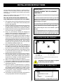
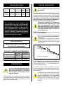
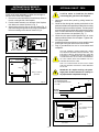
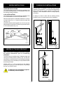
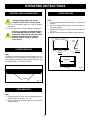
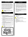
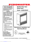
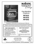
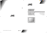
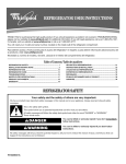
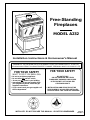
Free-Standing
Fireplaces
MODEL A232
Installation Instructions & Homeowner's Manual
WARNING! IF THE INFORMATION IN THIS MANUAL IS NOT FOLLOWED EXACTLY, A FIRE OR
EXPLOSION MAY RESULT CAUSING PROPERTY DAMAGE, PERSONAL INJURY OR LOSS OF LIFE.
FOR YOUR SAFETY
FOR YOUR SAFETY
WHAT TO DO IF YOU SMELL GAS:
*
*
*
*
Do not try to light any appliance.
Do not touch any electric switch
Do not use any phone in your building.
Immediately call your gas supplier from
your neighbours phone. Follow the gas
suppliers instructions.
* If you cannot reach your gas supplier call
the fire department.
DO NOT STORE
OR USE GASOLINE OR OTHER
FLAMMABLE VAPOURS AND LIQUIDS
IN THE VICINITY OF THIS OR ANY
OTHER APPLIANCE.
* INSTALLATION AND SERVICE MUST BE
PERFORMED BY A QUALIFIED INSTALLER,
SERVICE AGENCY OR YOUR GAS SUPPLIER.
INSTALLER: DO NOT DISCARD THIS MANUAL - LEAVE FOR HOMEOWNER
10002734
6/00 Rev. 0
TABLE OF CONTENTS
PLEASE READ THE INSTALLATION & OPERATING INSTRUCTIONS BEFORE USING APPLIANCE.
IMPORTANT: Read all instructions and warnings carefully before starting installation. Failure to follow these
instructions may result in a possible fire hazard and will void the warranty.
Installation Instructions.................................................................................................. 3
Important Curing/Burn Information ....................................................................... 3
Locating Your Fireplace ........................................................................................ 3
Clearance to Combustibles .................................................................................. 3
Fireplace Dimensions ........................................................................................... 4
Gas Specifications ................................................................................................ 5
Preparation ........................................................................................................... 5
Gas Line Installation ............................................................................................. 5
Installation of Remote Switch for RN/RP gas valve .............................................. 6
Fan Kit .................................................................................................................. 6
General Information on Assembling the Vent Pipes ................................................... 7
Venting Instructions .............................................................................................. 7
Venting of the A232 Fireplace .............................................................................. 7
Common Flue Installation ..................................................................................... 7
Retrofitting to an Existing Brick Chimney ............................................................. 8
Vent Safety System .............................................................................................. 8
Proper Vent Performance ..................................................................................... 8
Combustion Air ..................................................................................................... 8
Operating Instructions.................................................................................................... 9
General Glass Information .................................................................................... 9
Louvre Removal ................................................................................................... 9
Trim Removal ....................................................................................................... 9
Glass Removal ..................................................................................................... 9
Glass Cleaning ................................................................................................... 10
Installation of Logs and Burner Lava Rock ......................................................... 10
Maintenance ....................................................................................................... 10
Cleaning Procedure ............................................................................................ 10
Flame Adjustment & Characteristics .................................................................. 11
Lighting and Operating Instructions .................................................................... 12
Troubleshooting Gas Control (SIT 630) .............................................................. 13
Troubleshooting Gas Control (Honeywell) .......................................................... 14
Replacement Parts List .............................................................................................. 15
Replacement Parts Pictorial ............................................................................... 16
Options ......................................................................................................................... 27
-2-
INSTALLATION INSTRUCTIONS
This gas fireplace should be installed by a qualified installer in
accordance with local building codes and with current CAN /
CGA-B149 (. 1 or .2) Installation codes for Gas Burning Fireplaces
and Equipment.
IMPORTANT:
PLEASE REVIEW THE FOLLOWING
CAREFULLY
FOR U.S.A Installations follow local codes and/or the current
National Fuel Gas Code. ANSI Z223.1.
Remove any plastic from trim parts before turning the fireplace
ON.
FOR SAFE INSTALLATION AND OPERATION OF
YOUR FIREPLACE PLEASE NOTE THE FOLLOWING:
It is normal for fireplaces fabricated of steel to give off some
expansion and/or contraction noises during the start up or
cool down cycle. Similar noises are found with your furnace
heat exchanger or car engine.
1. This fireplace gives off high temperatures and should
be located out of high traffic areas and away from
furniture and draperies.
2. Children and adults should be alerted to the hazards of
the high surface temperatures of this fireplace and
should stay away to avoid burns or ignition of clothing.
3. Children should be carefully supervised when they are
in the same room as your fireplace.
4. Under no circumstances should this fireplace be
modified. Parts removed for servicing should be replaced prior to operating this fireplace again.
5. Installation and any repairs to this fireplace should be
carried out by a qualified service person. A professional service person should be contacted to inspect
this fireplace annually. Make it a practice to have all of
your gas fireplaces checked annually. More frequent
cleaning may be required due to excess lint and dust
from carpeting, bedding material, etc.
6. Control compartments, burners and air passages in
this fireplace should be kept clean and free of dust and
lint. Make sure that the gas valve and pilot light are
turned off before you attempt to clean this fireplace.
7. The venting system(chimney) of this fireplace should
be checked at least once a year and if needed your
venting system should be cleaned.
8. Keep the area around your fireplace clear of combustible materials, gasoline and other flammable vapour
and liquids. This fireplace should not be used as a
drying rack for clothing, nor should Christmas stockings or decorations be hung in the area of it.
9. Under no circumstances should any solid fuels (wood,
coal, paper or cardboard etc.)be used in this fireplace.
10. The flow of combustion and ventilation air must not be
obstructed in any way.
11. When the fireplace is installed directly on carpeting,
vinyl tile or any combustible material other than wood,
the fireplace must be installed on a metal or wood
panel extending the full width and depth of the fireplace.
12. This fireplace requires adequate ventilation and
combustion air to operate properly.
13. This fireplace must not be connected to a chimney flue
serving a separate solid fuel burning fireplace.
It is not unusual for your gas fireplace to give off some odour
the first time it is burned. This is due to the curing of the paint
and any undetected oil from the manufacturing process.
Please ensure that your room is well ventilated - open all
windows.
It is recommended that you burn youf fireplace for a least six
(6) hours the first time you use it. If optional fan kit has been
installed, place fan in the "OFF" position during this time.
LOCATING YOUR GAS FIREPLACE
12" (305mm)
A
12" (305mm)
D
B
C
F
E
Fig. 1
A) *Flat on wall corner
C) Island
E) Flat on wall
B)
D)
*Room divider
Cross corner
* A & B must maintain a 12" (305mm) clearance between the wall
and side glass of fireplace.
A minimum 12 foot vent height is required
to effectively vent this fireplace.
CLEARANCES TO COMBUSTIBLES
Adequate clearances as listed below must be
maintained for servicing and proper operation.
BACK... ...................................... 1"
SIDES.. .................................... 12"
COMBUSTIBLE FLOOR.. .......... 0"
TOP.... ...................................... 36"
CORNER ............ 0" to back edges
Flue Pipe Clearances - 6" Single Wall, 1"B" Vent.
-3-
FIREPLACE DIMENSIONS
MODEL A232
A
K
C
DE
G
I
J
F
H
B
MODEL A232
A
25"
635mm
B
24 1/8"
613mm
C
16"
406mm
D
20"
508mm
E
19"
483mm
F
21"
533mm
G
31 3/4"
806mm
H
17
3/4"
451mm
I
29
5/8"
752mm
J
9"
1/4"
229mm
K
5
133mm
L
–
–
M
–
–
N
–
–
-4-
GAS LINE INSTALLATION
GAS SPECIFICATIONS
MAX.
INPUT
GAS CONTROL B.T.U.H
When purging gas line, the front glass must
be removed.
MIN.
INPUT
B.T.U.H.
MODEL
FUEL
A232RN
Natural Gas
Millivolt Hi/Lo
30,000
21,000
A2S32RP
Propane Gas
Millivolt Hi/Lo
30,000
22,500
The gas pipeline can be brought in through the rear of the
fireplace as well as the bottom. Knockouts are provided on
the bottom behind the valve to allow for the gas pipe
installation and testing of any gas connection. It is most
convenient to bring the gas line in from the rear right
side of the valve, as this allows fan installation or
removal without disconnecting the gas line.
The gas line connection can be made with
properly tinned 3/8" copper tubing, 3/8" rigid
pipe or an approved flex connector. Since
some municipalities have some additional
local codes, it is always best to consult your
local authority and the CAN/CGA- B149 (.1 or
.2) installation code.
The installation of your Fireplace must
conform with local codes, or in the absence
of local codes, with National Fuel Gas Code,
ANSI Z223.1 latest edition, or CAN 1 B1-149.1
and .2 Installation Code. (EXCEPTION: Do
not derate this appliance for elevations up to
4,500 ft. (1,370mm). Maintain the manifold
pressure at 3.5 inches W.C. for Natural Gas
and 10 inches W.C. for LP gas.)
FOR U.S.A Installations consult the current National
Fuel Gas Code, ANSI Z223.1
Always check for gas leaks with a mild soap and
water solution. Do not use an open flame for
leak testing.
The gas control is equipped with a captured
screw type pressure test point, therefore it is not
necessary to provide a 1/8" test point up stream
of the control.
A232 CERTIFIED TO
ANSI.Z21.88b-1999 / CSA 2.33b - M99
Vented Gas Fireplace Heaters
1/2" GAS SUPPLY
1/2" X 3/8" REDUCER
3/8" NIPPLE
GAS INLET & MANIFOLD PRESSURES
Input Minimum
Input Maximum
Manifold Pressure
NATURAL
LP (Propane)
4.5" wc
11" wc
7" wc
13" wc
3.5" wc
10" wc
3/8" X 3/8" SHUT OFF VALVE
3/8" NIPPLE
3/8" UNION
3/8" NIPPLE
Typical gas supply installation
Fig. 2
When using copper or flex connector use only approved
fittings. Always provide a union when using black iron
pipe so that gas line can be easily disconnected for burner
or fan servicing. See Fig. 2. See gas specification for
pressure details and ratings.
PREPARATION
The fireplace valve must not be subjected to any test
pressures exceeding 1/2 psi. Isolate or disconnect this or
any other gas appliance control from the gas line when
pressure testing.
The use of wall paper adjacent to this fireplace is not recommended, as the high heat
given off by this fireplace may adversely
effect the binders in the adhesive used to
apply the wallpaper.
DO NOT USE THIS FIREPLACE IF ANY PART
OF THIS FIREPLACE HAS BEEN UNDER
WATER. IMMEDIATELY CALL A QUALIFIED
SERVICE TECHNICIAN TO INSPECT THE
HEATER AND TO REPLACE ANY PART
CONTROL WHICH HAS BEEN UNDER
WATER.
Before beginning, remove the glass door from the fireplace
(See page 9). Also check to make sure there is no hidden
damage to the fireplace. Take a minute and plan out the
gas, vent and electrical supply.
-5-
INSTALLATION OF REMOTE
SWITCH FOR RN/RP GAS VALVE
OPTIONAL FAN KIT - FK24
It will be easier to install the fan before
connecting the gas line to the fireplace.
Install on/off switch assembly on either the rear right or
left side of the A232 Gas Fireplace.
1. Remove the screw at the back of the cabinet top either on
the left or the right side of the fireplace.
2. Position switch assembly onto the back of the fireplace,
then fasten two screws as shown in Fig. 5.
3. Attach wiring under the clips on the rear casing (Fig. 5)
and install wiring through the rear opening of the fireplace
before connecting to the valve as shown in Fig. 4.
1. Open front access door panel by pulling forward on
brass lip.
2. Guide the fan through the opening at the back of the
pedestal, with the outlet pointed up and the fan mounting
bracket facing the back of the fireplace. The fan mounts
over two studs which hold the fan just below the firebox
floor. Do not install this fan on the base. Hold the fan
in place with the two nuts provided. (Fig. 7)
3. Locate the fan speed control/junction box on screw
studs provided on base of the fireplace. Tighten with
3/8" nuts provided.
4. Install thermal sensor element on screw studs located
to the right of the gas valve on the burner base.
5. Plug in grounded service cord to a convenient wall
receptacle.
VALVE
TH
TPTH
THERMOPILE
TP
TP
PILOT
ADJ
TP
TH
TH
OT
PIL
ON/OFF SWITCH OR
MILLIVOLT THERMOSTAT
THIS FAN ASSEMBLY COMES COMPLETELY WIRED
TO ELIMINATE THE NEED FOR ELECTRICIANS. THIS
ELECTRICAL DEVICE, WHEN INSTALLED, MUST BE
ELECTRICALLY CONNECTED AND GROUNDED IN
ACCORDANCE WITH LOCAL CODES. IN THE ABSENCE
OF LOCAL CODES, WITH THE CURRENT CSA C22.1
CANADIAN ELECTRICAL CODE.
Fig. 4
On/off switch
assembly
Screw
(through existing hole)
Screw
FOR U.S.A. INSTALLATION: FOLLOW LOCAL CODES
AND THE NATIONAL ELECTRICAL CODE ANSI/NFPA
NO.70-1984.
Clips
Should this fan require servicing, the power
supply must be disconnected. For rewiring of
any replacement components see Fig. 6.
Wiring for milli-volt
gas valves
A = Speed Control
B = Temperature Sensor
C = Fan
Fig. 5
C
B
A
BLACK
WHITE
GROUND
Fig. 6
Stud
Thermal sensor
location
Fan is installed at the back
of the pedestal
Valve
Fan speed control/
Junction box
TOP VIEW
-6-
Fig. 7
VENTING INSTRUCTIONS
COMMON FLUE INSTALLATIONS
CANADIAN INSTALLATIONS:
The venting system must be installed in accordance with
the current CAN/CGA-B149 (.1 or.2) installation code, and
the authority having jurisdiction.
In some areas it is possible to vent more than one gas
fireplace into the same flue. You must ensure that the flue
being shared has the proper capacity to handle both
fireplaces. Check installation codes for venting capacity
information.
U.S.A. INSTALLATIONS:
The venting system must be installed in accordance with
the current National Fuel Gas Code, ANSI Z223.1.
As always it is best to check with the authority having
jurisdiction prior to commencement of the installation.
Minimum clearances to combustible materials is 1 inch (25
mm) for B Vent (Fig. 13, 15) and 6 inches for single wall
vent (Fig. 14).
As with any natural drafted appliances, the vent cap must
always extend a minimum of 2' above any structure within
a 10' horizontal plane.(Fig. 12)
2'
10'
3'
10'
3'
Fig. 12
EXISTING
MASONRY CHIMNEY
OFFSET B
VENT CHIMNEY
Fig. 14
Fig. 13
VENTING OF THE A232 FIREPLACE
Note: Please refer to installation instructions supplied
by chimney manufacturer prior to commencing
installation.
The A232 may be installed using 4" diameter single wall
vent up to an existing masonry chimney.(Fig. 14) This vent
should then be connected to a 4" liner running the full height
of the chimney, as it is mandatory in most jurisdictions that
the chimney be lined.
Another option is 4" "B" vent directly off the fireplace
(Fig.13 & 11), going up to the chimney liner or up through
the roof if no chimney exists.
A minimum 12 foot vent height is required
to effectively vent this fireplace.
STRAIGHT B
VENT CHIMNEY
Fig. 15
-7-
PROPER VENT PERFORMANCE
Retrofitting To An Existing Brick Chimney
It is strongly recommends installing an approved chimney
liner in an existing brick chimney.
This will maximize the potential draft of the chimney and
lessen the effects of slow chimney start up.
Check
Draft
Here
This is important because many homes (including older
renovated ones) have become much tighter with respect to
air exchange (a home breathing). An overly tight home will
create conditions that will affect proper vent performance.
It may be necessary to install some form of makeup air to
the lowest extremities of the home. This will help to ensure
the above noted condition will not effect the proper operation
of this or any other combustion fireplace within the dwelling.
Fig. 16
A spillage test must be performed prior to leaving the
fireplace with the customer. Carry this test out in the
following manner.
VENT SAFETY SYSTEM
1) Close all windows and doors in the room; start all
exhaust fans in the house and furnace blower.
2) Light the fireplace and place in operation on high fire.
3) After several minutes, test with smoke match that there
is adequate "pull" at the draft hood opening (located on
the sides of the fireplace near back. See Figure 16)
If the flue is blocked (match being blown back into
room) the Vent Safety Switch will automatically shut
down the heater.
4) Should the heater turn off, wait approximately 10-15
minutes to allow for the switch to reset. Check draft
again. If the smoke is not drawn into the draft hood turn
the fireplace off and check the cause of lack of draft,
consult your dealer for expert advice.
This fireplace is equipped with a vent safety shut down
switch. This switch is factory installed, wired and tested.
Check and make sure the switch and wires are in the proper
position. The safety switch is heat activated and wired in
series with the pilot system.
Operation of this fireplace when not
connected to a properly installed and
maintained venting system or tampering with
the vent safety shutoff system can result in
carbon monoxide (CO) poisoning and possibly
death.
COMBUSTION AIR
It is very important that an adequate air supply is available
when the unit is being operated. Since most homes of
today are tightly sealed and insulated, additional makeup air is usually necessary.
This fireplace has been designed to operate by drawing air
in from the front and outer perimeters of the fireplace. The
air provides combustion air ensuring a clean burning
flame, dilution air for proper venting, as well as, the air
which the fan circulates over the firebox/heat exchanger
system.
Insulating around the fireplace will result in overheating
and possible malfunctioning of the circulating fan.
-8-
OPERATING INSTRUCTIONS
GLASS REMOVAL
GENERAL GLASS INFORMATION
A232
1 . Remove frame window brass trim (See Trim Removal
section)
2. Remove remaining bottom 3/8" nut fat the bottom of
the frame window.
3. Remove 3/8" nut from each side of the frame window
(Fig. 18).
4. Remove frame window by pulling it forward and up.
Only glass approved for use in these
products may be used for replacement.
1. The use of substitute glass will void all product
warranties.
2. Care must be taken to avoid breakage of the glass.
Under no circumstances should this fireplace
be operated without the front glass or with a
broken glass. Replacement of the glass (with
gasket) as supplied by the manufacturer
should be done by a licenced qualified
service person.
GLASS
FRAME
LOUVRE REMOVAL
OUTER NUTS
DRAWING 2
DRAWING 1
A232
To remove louvres first remove the two (2) screws (Fig. 17)
fastening the louvre assembly to the fireplace. Lift the
louvre assembly straight out sliding the back guides out of
the fireplace body. (To reinstall, reverse).
Side Nuts
Front View
BOTTOM NUT
Screws
Fig. 17
TRIM REMOVAL
A232
1. Remove the two (2) outer 3/8" nuts holding the frame
window brass trim in place. (Fig. 18)
2. Remove the frame window brass trim by moving it
straight forward.
-9-
Fig. 18
GLASS CLEANING
MAINTENANCE
It will be necessary to clean the glass periodically.
During start-up condensation, which is normal, forms on
the inside of the glass and causes lint, dust and other
airborne particles to cling to the glass surface. Also
initial paint curing may deposit a slight film on the glass.
It is therefore recommended that the glass be cleaned
two or three times with a non-ammonia household
cleaner and warm water (we recommend gas fireplace
glass cleaner). After that the glass should be cleaned
two or three times during each heating season
depending on the circumstances present.
1. It is important to keep the burner and the burner
compartment clean. This must be done periodically, at
least once per season. (See Cleaning Procedure).
2. Clean the brass trim using a soft clean cloth, slightly
dampened with lemon oil and buff with a soft clean
cloth. Do NOT use brass polish or household cleaners
as these products will damage the brass trim. Lemon
oil can be obtained at supermarkets or hardware
stores.
3. The optional FK12 and FK24 Fan requires periodic
cleaning. Check the fan and the area around the fan
assembly and wipe or vacuum at least once per month
during the operating season.
4. Contact your local representative to arrange an annual
service program.
Clean glass after first two weeks of
operation.
INSTALLATION OF LOGS &
BURNER LAVA ROCK
CLEANING PROCEDURE
A232
1 . Remove front glass. (See "Glass Removal" section)
2. Remove logs from packaging.
3. Place rear log (KR4) on rear bracket (ensure log is
seated properly, leveled and centered to the unit), so it
will not move from side to side and it is firmly positioned
on the bracket.
4. Slip front ember log (KR1) down in the front deflector.
5. Place front left log (KR2) on top burner, left side. Use
log's bottom holes to locate it into the left bracket log
locator studs.
6. Place front right log (KR3) on top of burner, right side.
Use log's bottom holes to locate it into the right bracket
log locator studs.
7. Place small lava rocks and ember material on top of
burner. (See Fig. 19 for proper location).
8. Place top left log (KR5) onto locator notches. Ensure
log is secure.
9. Place top right log (KR6) onto locator notches. Ensure
log is secure.
;;
;
;
;;
1.
2.
3.
CAUTION: LOGS MAY BE HOT
4.
5.
6.
7.
8.
9.
Top logs must be placed properly into
notches
KR5
KR6
KR4
KR2
Turn off pilot light at gas valve.
Remove front glass.
Remove logs.
KR3
KR1
Burner Lava Rock Placement
Fig. 19
- 10 -
Vacuum burner compartment especially around orifice/
primary air openings.
Reinstall logs.
Check pilot and main burner operation.
Reinstall front glass.
Recheck pilot and main burner operation.
Check visually the flame pattern and compare with Fig.
22 or 23.
FLAME ADJUSTMENT (RN/RP MODELS)
FLAME CHARACTERISTICS
It is important to periodically perform a visual
check of the pilot and the burner flames.
Compare them to the pictorials illustrated
below (Fig. 22, 23). If any of the flames
appear abnormal call a service person.
For units equipped with Hi/Lo valves, flame adjustment
is accomplished by rotating the Hi/Lo adjustment knob
located near the centre of the gas control. (Fig. 20a & b)
HI
Turn
counterclockwise
to increase
flame height.
3/8" - 1/2"
Turn clockwise
to lower
flame height.
SIT VALVE
LO
L
O H
Turn
counterclockwise
to decrease
flame height.
I
Fig. 20a
Turn clockwise
to increase
flame height.
PSE VALVE
Fig. 20b
Fig. 22
A232
Fig. 23
- 11 -
LIGHTING AND OPERATING INSTRUCTIONS
FOR YOUR SAFETY READ BEFORE LIGHTING
WARNING: If you do not follow these instructions exactly, a fire or explosion may result
causing property damage, personal injury or loss of life.
A.
This fireplace has a pilot which must be lit manually.
When lighting the pilot follow these instructions exactly.
BEFORE LIGHTING smell all around the fireplace area for
gas. Be sure to smell next to the floor because some gas
is heavier than air and will settle on the floor.
B.
WHAT TO DO IF YOU SMELL GAS
•
Do not try to light any fireplace.
•
Do not touch any electric switch
•
Do not use any phone in your building
•
Immediately call your gas supplier from a neighbor's
phone. Follow the gas supplier's instructions.
•
If you cannot reach your gas supplier, call the Fire
Department
C.
Use only your hand to push in or turn the gas control
knob. Never use tools. If the knob will not push in or turn
by hand, do not try to repair it, call a qualified service
technician. Applying force or any attempted repair may
result in a fire or explosion.
D.
Do not use this fireplace if any part has been under water.
Immediately call a qualified service technician to inspect
the fireplace and to replace any part of the control system
and any gas control which has been under water.
LIGHTING INSTRUCTIONS
1.
STOP! Read the safety information above on this
label
Turn off all electrical power to the fireplace.
For MN/MP/TN/TP appliances ONLY, go on to Step 4.
For RN/RP appliances turn the On/Off switch to off
position or set thermostat to lowest level.
Open control access panel.
Push in gas control knob slightly and turn clockwise
to
"OFF". Do not force.
2.
3.
4.
5.
10. Push the control knob all the way in and hold.
Immediately light the pilot by repeatedly depressing
the piezo spark ignitor until a flame appears.
Continue to hold the control knob in for about one
(1) minute after the pilot is lit. Release knob and it
will pop back up. Pilot should remain lit. If it goes
out, repeat steps 5 through 8.
OR
PI
LO
T
OFF
7.
8.
9.
PI LOT
6.
F
LO
OT
EURO SIT
ON
ON
it
PIL
OF
HI
OFF
SIT NOVA
HONEYWELL
Wait five (5) minutes to clear out any gas. Then smell
for gas, including near the floor. If you smell gas,
STOP! Follow "B" in the safety information above on
this label. If you don't smell gas, go to the next step.
Remove glass door before lighting pilot. (See Glass
Frame Removal in manual).
Visibly locate pilot by the main burner.
Turn knob on gas control counterclockwise
to "PILOT".
11.
12.
13.
14.
• If knob does not pop up when released, stop and
immediately call your service technician or gas
supplier.
• If after several tries, the pilot will not stay lit, turn
the gas control knob to "OFF" and call your service
technician or gas supplier.
Replace glass door.
Turn gas control knob to "On"
position.
For Rn/RP appliances turn the On/Off switch to "On"
positin or set thermostat to desired setting.
Turn on all electrical power to the fireplace.
TO TURN OFF GAS TO FIREPLACE
1.
2.
3.
Turn the On/Off switch to Off position or set the
thermostat to lowest setting.
Turn off all electric power to the fireplace if service
is to be performed.
Open control access panel.
4.
5.
- 12 -
Push in gas control knob slightly
and turn clockwise
to
"OFF". Do not force.
Close control access panel.
TROUBLE SHOOTING THE GAS CONTROL SYSTEM
SIT NOVA 820 MILLIVOLT VALVE
Note: Before trouble shooting the gas control system, be sure external gas shut off is in the "On" position.
WARNING: BEFORE DOING ANY GAS CONTROL SERVICE WORK, REMOVE GLASS FRONT.
SYMPTOM
1. Spark ignitor will not light
2. Pilot will not stay lit after
carefully following lighting
instructions.
3. Pilot burning, no gas to
burner, Valve knob "ON",
Wall Switch "ON".
4. Frequent pilot flare outage
problem.
POSSIBLE CAUSES
CORRECTIVE ACTION
A. Defective or misaligned
electrode at pilot.
Using a match, light pilot. If pilot lights, turn off pilot and
push the red button again. If pilot will not light - check gap
at electrode and pilot-should be 1/8" to have a strong spark.
B. Defective ignitor (Push Button)
Push Piezo Ignitor Button. Check for spark at electrode and
pilot. If no spark to pilot, and electrode wire is properly
connected, replace ignitor.
A. Defective pilot generator
(thermocouple), remote wall
switch.
1. Check pilot flame. Must impinge on thermocouple/
thermopile. Note: this pilot burner assembly utilizes both
a thermocouple and a thermopile. The thermocouple
operates the main valve operation (On and Off). Clean
and or adjust pilot for maximum flame impingement on
thermopile and thermocouple.
B. Defective automatic valve
operator.
Turn valve knob to "Pilot". Maintain flow to pilot; millivolt
meter should read greater than 10 mV. If the reading is
okay and the pilot does not stay on, replace the gas
valve. Note: An interrupter block (not supplied) must be
used to conduct this test.
A. Wall switch or wires
defective.
Check wall switch and wires for proper connections. Jumper
wire across terminals at wall switch, if burner comes on,
replace defective wall switch. If okay, jumper wires across
wall switch wires at valve, if burner comes on, wires are
faulty or connections are bad.
B. Thermopile may not be
generating sufficient
millivoltage.
1. Be sure wire connections from thermopile at gas valve
terminals are tight and thermopile is fully inserted into pilot
bracket.
2. One of the wall switch wires may be grounded. Remove
wall switch wires from valve terminals if pilot now stays lit,
trace wall switch wiring for ground. May be grounded to
fireplace or gas supply.
3. Check thermopile with millivolt meter. Take reading at
thermopile terminals of gas valve. Should read 250-300
millivolts (minimum 150) while holding valve knob depressed in pilot position and wall switch "Off". Replace
faulty thermopile if reading is below specified minimum.
C. Plugged burner orifice.
Check burner orifices for debris and remove.
D. Defective automatic valve
operator.
Turn valve knob to "On", place wall switch to "On" millivolt
meter should read greater than 100 mV. If the reading is
okay and the burner does not come on, replace the gas
valve.
A. Pilot flame may be too low
or blowing (high) causing the
pilot safety to drop out.
Clean and/or adjust pilot flame for maximum flame
impingement on thermopile and thermocouple.
B. Vent safety shutdown.
Check the vent system for blockage. Check all connections
on vent safety switch.
- 13 -
TROUBLE SHOOTING THE GAS CONTROL SYSTEM
HONEYWELL MILLIVOLT VALVE
START
CHECK
• GAS SUPPLY ON
NO
YES
PILOT LIGHTS WITH
PIEZO IGNITOR
NO
YES
PILOT STAYS LIT
YES
• LOCKOUT HAS ENGAGED. WAIT
60 SECONDS AND TRY AGAIN.
• FOR SPARK AT ELECTRODE
WHILE DEPRESSING PIEZO
— 1/8" GAP TO
PILOT HOOD NEEDED.
• ALL WIRING CONNECTIONS
• REPLACE PIEZO IGNITOR
NO
• FOR AIR IN THE LINES
• THERMOPILE NEEDS A
MINIMUM 325mV. ADJUST
PILOT FLAME HEIGHT.
• ALL WIRING CONNECTIONS.
• REPLACE THERMOPILE
• THERMOCOUPLE NEEDS A
MINIMUM OF 14mV.
• DEFECTIVE VALVE. TURN TO
PILOT, METER SHOULD READ
GREATER THAN 100 mV. IF
NOT, REPLACE.
NO
• VALVE IS TURNED ON
• ON/OFF SWITCH IS NOT
TURNED ON. WATCH
FOR GROUNDED WIRES!
• THERMOPILE NEEDS A
MINIMUM 325mV.
• PLUGGED BURNER ORIFICE.
YES
PILOT LIGHTS MAIN
BURNER
• SUPPLY LINE HOOKED UP
• SHUTOFF VALVE OPEN
SYSTEM OK.
- 14 -
REPLACEMENT PARTS LIST
DESCRIPTION
1.
1a.
1b.
1c.
1d.
1e.
1f.
2.
3a.
3b.
4.
5a.
5b.
6a.
6b.
7a.
7b.
8a.
8b.
9a.
9b.
10a.
10b.
11.
12.
13.
14.
15.
16.
17.
18.
19.
20.
21a.
21b.
22.
23.
24a.
24b.
25a.
25b.
26.
27.
28.
29.
30.
31.
32.
33.
36a.
36b.
37.
39.
41.
42.
43.
44.
45.
46.
47.
48.
A232
Log Set Complete
Log Ember Front
Log Front Left
Log Front Right
Log Rear
Log Top Left
Log Top Right
Burner Lava Rock (Package)
Burner with Tiles Nat.
Burner with Tiles Prop.
Ceramic Tile (single)
Orifice Front Nat.
Orifice Front Prop.
Orifice Main Nat.
Orifice Main Prop.
Orifice Pilot SIT Nat.
Orifice Pilot SIT Prop.
Orifice Pilot PSE Nat.
Orifice Pilot PSE Prop.
Pilot Assembly SIT Nat.
Pilot Assembly SIT Prop.
Pilot Asssembly PSE Nat.
Pilot Assembly PSE Prop.
Pilot SIT
Pilot w/ignitor and cable PSE
Pilot Tubing w/fittings
Manifold Tubing w/fittings
Thermocouple with Interrupter SIT
Thermocouple with Interrupter PSE
Thermopile
Electrode Ignitor w/cable SIT
Ignitor Piezo SIT
Ignitor Piezo Honeywell
Valve SIT 820 Nat.
Valve SIT 820 Prop.
Extension Knob Hi/Lo (RN/RP)
Extension Knob (On/Off) SIT (RN/RP)
Valve Honeywell Nat.
Valve Honeywell Prop.
Valve Eurosit 630 Nat.
Valve Eurosit 630 Prop.
Fan with Bracket
Electrical Cord (6ft.)
Fan Temperature Sensor
Speed Control
Speed Control Knob
Glass with Gasket -Front
Glass with Gasket - Side
Gasket Glass
Frame Window - Left Side
Frame Window - Right Side
Frame Window - Front
Trim Frame Window (PB)
Top Louvre
Front Louvre Assembly
Access Door with Handle
Latch
Remote Switch
Remote Wire Harness with Terminals
Vent Safety Switch
Vent Safety Switch Wiring Harness
10000160
KR1
KR2
KR3
KR4
KR5
KR6
57897
10000198
57904
57803
SEE RATING PLATE FOR ORIFICE SIZE
SEE RATING PLATE FOR ORIFICE SIZE
SEE RATING PLATE FOR ORIFICE SIZE
SEE RATING PLATE FOR ORIFICE SIZE
54273
54272
10001822
10001823
54219
54221
10001739
10001740
10001295
10001824
53211
57318
54912
10001828
53374
52465
52464
2000062
52677
52678
10000165
10000166
10001782
10001759
51844
51845
54103
51865
51704
51738
51882
52035
52032
57316
55110
55111
55109
52027
53977
57907
52052
52057
53606
57265
51866
54849
- 15 -
REPLACEMENT PARTS
42
41
4
42
11
3a/b
18
43
29
43
5/6a/b
15
17
13
44
9 a/b
49
33
22
32
31
19
7a/b
30
10 a/b
23
33
28
14
26
LO
36 a/b
PIL
37
it
OT
OF F
HI
25a/b
39
47
16
2
12 17
27
48
8 a/b
46
41
21a,b
PI
LO
T
PILOT
ADJ
ON
I
OFF
L
45
O H
42
20
43
#1 - COMPLETE LOG SET -- A232
1d
40
40
39
1f
1e
1b
1c
1a
- 16 -
24 a/b
OPTIONS
REMOTE CONTROL
For units with RN/RP valves
MRC1 - On/Off Button Remote Control
MRC2 - Temperature Control Remote
MRC3 - Temperature Control w/digital display &
24 hour programmable clock
IMT
- Wall Mounted Thermostat
- 17 -
LIMITED WARRANTY & EXTENDED LIFE TIME PROTECTION
For Gas Appliance Products*
BASIC WARRANTY:
The CFM Majestic, Inc.™ (hereinafter referred to collectively as the
"Company") warrants that your new Vermont Castings Gas Appliance is
free from manufacturing and material defects for a period of one year
from date of installation, subject to the following conditions and
limitations.
EXTENDED LIFE TIME WARRANTY:
The heat exchanger, combustion chamber and ceramic burner parts of
every *CFM Majestic, Inc. product are warranted for life to the original
owner, subject to proof of purchase and the following conditions and
limitations:
1. This new CFM Majestic, Inc. product must be installed by a competent,
authorized service contractor. It must be installed and operated at all times
in accordance with the Installation and Operating instructions furnished
with the product. Any alteration, willful abuse, accident, or misuse of the
product shall nullify this warranty.
2. This warranty is non-transferrable, and is made to the original owner,
provided that the purchase was made through an authorized supplier of
the Company.
3. This warranty is limited to the repair or replacement of part(s) found to be
defective in material or workmanship, provided that such part(s) have been
subjected to normal conditions of use and service, after said defect is
confirmed by the Company's inspection.
4. The Company may, at its discretion, fully discharge all obligations with
respect to this warranty by refunding the wholesale price of the defective
part(s).
5. Any installation, labour, construction, transportation, or other related costs/
expenses arising from defective part(s), repair, replacement, or otherwise
of same, will not be covered by this warranty, nor shall the Company assume
responsibility for same. Further, the Company will not be responsible for
any incidental, indirect, or consequential damages, except as provided by
law.
6. All other warranties - expressed or implied - with respect to the product, its
components and accessories, or any obligations/liabilities on the part of
the Company are hereby expressly excluded.
7. The Company neither assumes, nor authorizes any third party to assume,
on its behalf, any other liabilities with respect to the sale of this CFM
Majestic, Inc. product.
8. The warranties as outlined within this document do not apply to chimney
components or other non CFM Majestic, Inc. accessories used in
conjunction with the installation of this product.
9.
The Company will not be responsible for . . .
a) Down drafts or spillage caused by environmental conditions such as
near-by trees, buildings, roof tops, hills, or mountains.
b) Inadequate ventilation or negative air pressure caused by mechanical
systems such as furnaces, fans, clothes dryers, etc.
10. This warranty is void if:
a) The fireplace has been operated in atmospheres contaminated by
chlorine, fluorine or other damaging chemicals.
b) The fireplace is subjected to prolonged periods of dampness or
condensation.
c) Any damage to the fireplace, combustion chamber, heat exchanger
or other components due to water, or weather damage which is the
result of, but not limited to, improper chimney/venting installation.
d) Any alteration, willful abuse, accident, or misuse of the product.
GLASS DOORS & BRASS PLATED PARTS
Glass doors are not warranted for breakage due to misuse or accident.
Brass parts should be cleaned with lemon oil only. Brass cleaners cannot be
used. Mortar mix and masonry cleaners may corrode the brass finish. The
Company will not be responsible for, nor will it warrant any brass parts which
are damaged by external chemicals or down draft conditions.
IF WARRANTY SERVICE IS NEEDED . . .
1) Contact your supplier. Make sure you have your warranty, your sales receipt,
and the model/serial number of your CFM Majestic, Inc. product.
2) DO NOT ATTEMPT TO DO ANY SERVICE WORK YOURSELF.
GARANTIE DE BASE:
The CFM Majestic. Inc. (aux présentes nommée la "Société") garantit votre
nouveau foyer au gaz CFM Majestic, Inc. contre tous défauts de fabrication
et de matières premières pour une période d'un an à compter de la date
d'installation, sujet aux conditions et limitations suivantes.
GARANTIE A VIE PROLONGEE:
Les pièces de l'échangeur de chaleur, de la chambre à combustion et du
brûleur en céramique de tout produit *CFM Majestic, Inc. sont garanties pour
la vie de l'acheteur d'origine, le tout sujet à une preuve d'achat et aux
conditions et limitations suivantes:
1.
Ce nouveau produit CFM Majestic, Inc. doit être installé par un entrepreneur
de service autorisé et compétent. Il doit être installé et utilisé en tout temps
selon les instructions d'installation et de fonctionnement fournies avec le
produit. Toute altération, abus volontaire, accident ou mauvais usage du produit
annulera cette garantie.
2. Cette garantie n'est pas transférable et est offerte à l'acheteur au détail
d'origine, à condition que l'achat soit effectué par l'entremise d'un détaillant
autorisé de la Société.
3. Cette garantie est limitée à la réparation ou au remplacement de(des) pièce(s)
trouvée(s) défectueuse(s) en matières premières ou main-d'oeuvre, à condition
que lesdites pièces aient été sujettes aux conditions normales d'usage et de
service, après que ledit défaut a été confirmé par une inspection par la Société.
4. La Société peut, à sa discrétion, se décharger entièrement de toutes obligations
se rapportant à cette garantie en remboursant le prix de gros de la(des) pièce(s)
défectueuse(s).
5. Tous les frais/dépenses d'installation, de main-d'oeuvre, de construction, de
transport ou autres causés par une (des) pièce(s) défectueuse(s), une
réparation, un remplacement ou autre, ne seront pas couverts sous cette
garantie, et la Société n'assume aucune responsabilité pour ceux-ci. De plus,
la Société ne pourra être tenue responsable pour tous dommages fortuits ou
indirects sauf la ou prévu par la loi.
6. Toutes autres garanties, exprimées ou sous-entendues, en ce qui a trait au
produit, ses composants et accessiores, ou toutes obligations/responsabilités
de la part de la Société sont aux présentes expressment excluses.
7. La Société n'assume et n'autorise personne à assumer, en son nom, toutes
responsabilités en ce qui a trait à la vente de ce produit CFM Majestic, Inc..
8. Les garanties, telles que décrites dans ce document, ne s'appliquent pas aux
compasants de cheminée ou aux autres accessoires non CFM Majestic, Inc.
utilisés conjointement pour l'installation de ce produit.
9. La Société n'encourrera aucune responsabilité pour . . .
a) Les refoulements de cheminées ou débordements causés par les
conditions environnementales comme par les arbres, les édifices, les toits,
les côteaux ou les montagnes adjacents.
b) Une ventilation inadéquate ou une pression d'air négative causée par
des systèmes mécaniques comme les fournaises, les ventilateurs, les
sécheuses, etc.
10. Cette garantie est nulle si:
a) Le foyer a été utilisé dans une atmosphère contaminée par du chlore, du
fluor ou tous autres produits chimiques.
b) Le foyer est assujetti à de longues périodes d'humidité ou de condensation.
c) Des dommages sont causés au foyer, à la chambre de combustion. à
l'échangeur de chaleur ou aux autres composants par de l'eau ou par la
température qui est le résultat mais sans y être limité, d'une mauvaise
installation de cheminée/ventilation.
d) Toute altération, abus volontaire, accident ou mauvais usage du produit
annulera cette garantie.
PORTES EN VERRE & PIECES PLAQUEES LAITON
Les portes en verre ne sont pas garanties contre le bris causé par un mauvais
usage ou un accident.
Les pièces en laiton devraient être nettoyées qu'avec de l'essence de citron. Les
nettoyeurs de laiton ne peuvent pas être utilisés. La Société ne sera pas
responsable pour, et ne garantit pas les pièces en laiton qui sont endommagées
par des conditions chimiques externes ou de refoulement.
1.
2.
SI UN SERVICE SOUS GARANTIE EST REQUIS . . .
Communiquez avec votre détaillant. Assurez-vous que vous avez votre
garantie, votre reçu de caisse ainsi que le numéro de modèle/série de votre
produit CFM Majestic, Inc.
NE TENTEZ PAS D'EFFECTUER DES REPARATIONS VOUS-MEME.
CFM Majestic, Inc.
410 Admiral Blvd. • Mississauga, Ontario, Canada L5T 2N6 • 905-670-7885
www.vermontcastings.com
- 18 -
© Copyright
CFM Majestic, Inc.
10002734 6/00