1
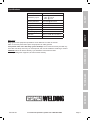
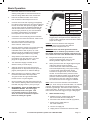
Table of Contents
SAFETY
Safety.......................................................... 2
Setup........................................................... 5
Specifications.............................................. 5
Operation.................................................... 10
Techniques................................................. 12
Maintenance............................................... 13
Troubleshooting.......................................... 14
Parts List and Diagrams............................. 18
Warranty..................................................... 22
WARNING SYMBOLS AND DEFINITIONS
This is the safety alert symbol. It is used to alert you to potential personal injury hazards.
Obey all safety messages that follow this symbol to avoid possible injury or death.
Indicates a hazardous situation which, if not avoided,
will result in death or serious injury.
SETUP
Indicates a hazardous situation which, if not avoided,
could result in death or serious injury.
Indicates a hazardous situation which, if not avoided,
could result in minor or moderate injury.
Addresses practices not related to personal injury.
OPERATION
IMPORTANT SAFETY INSTRUCTIONS
General Tool Safety Warnings
Read all safety warnings and instructions.
Failure to follow the warnings and instructions may result in electric shock, fire and/or serious injury.
Save all warnings and instructions for future reference.
TECHNIQUES
1.
Maintain labels and nameplates on the tool.
These carry important information.
If unreadable or missing, contact
Harbor Freight Tools for a replacement.
2.
Maintain a safe working environment.
Keep the work area well lit. Make sure
there is adequate surrounding workspace.
Keep the work area free of obstructions, grease,
oil, trash, and other debris. Do not use in areas
near flammable chemicals, dusts, and vapors.
Do not use in a damp or wet location.
3.
SERVICE
Avoid unintentional starting. Make sure
switch is in off position before plugging in.
Make sure you are prepared to begin
work before turning on the tool.
4.
Never leave the tool unattended when
it is plugged into an electrical outlet.
Turn off the tool, and unplug it from its electrical
outlet before leaving. Unplug the tool from
its electrical outlet before performing
any inspection, maintenance, or cleaning
procedures, including changing accessories.
5.
Prevent eye injury and burns. Wearing personal
protective equipment reduces the risk for injury.
• Wear an ANSI‑approved welding helmet featuring
at least a number 10 shade lens rating.
• Leather leggings, fire resistant shoes or
boots should be worn when using this
product. Do not wear pants with cuffs, shirts
with open pockets, or any clothing that can
catch and hold molten metal or sparks.
• Keep clothing free of grease, oil, solvents,
or any flammable substances. Wear dry,
insulating gloves and protective clothing.
Page 2
For technical questions, please call 1-800-444-3353.
SKU 95136
Exposure to welding or cutting
exhaust fumes can increase
the risk of developing certain cancers,
such as cancer of the larynx and lung cancer.
Also, some diseases that may be linked to
exposure to welding or cutting exhaust fumes are:
• Early onset of Parkinson’s Disease
• Heart disease
• Ulcers
• Damage to the reproductive organs
• Inflammation of the small intestine or
stomach
• Kidney damage
• Respiratory diseases such as
emphysema, bronchitis, or pneumonia
Use natural or forced air ventilation
and wear a respirator approved by
NIOSH to protect against the fumes
produced to reduce the risk of
developing the above illnesses.
• When possible, move the work to a location well
away from combustible materials. If relocation
is not possible, protect the combustibles with
a cover made of fire resistant material.
• Remove or make safe all combustible
materials for a radius of 35 feet (10 meters)
around the work area. Use a fire resistant
material to cover or block all open doorways,
windows, cracks, and other openings.
• Enclose the work area with portable fire
resistant screens. Protect combustible
walls, ceilings, floors, etc., from sparks
and heat with fire resistant covers.
• If working on a metal wall, ceiling, etc.,
prevent ignition of combustibles on the other
side by moving the combustibles to a safe
location. If relocation of combustibles is not
possible, designate someone to serve as a
fire watch, equipped with a fire extinguisher,
during the cutting process and for at least
one half hour after the cutting is completed.
10.
• Do not weld or cut on materials having a
combustible coating or combustible internal
structure, as in walls or ceilings, without an
approved method for eliminating the hazard.
• Where ventilation is questionable, have a
qualified technician take an air sampling to
determine the need for corrective measures.
Use mechanical ventilation to improve
air quality. If engineering controls are not
feasible, use an approved respirator.
• Do not dispose of hot slag in containers
holding combustible materials. Keep a fire
extinguisher nearby and know how to use it.
• Work in a confined area only if it is well ventilated,
or while wearing an air-supplied respirator.
• After welding or cutting, make a thorough
examination for evidence of fire. Be aware
that easily visible smoke or flame may not
be present for some time after the fire has
started. Do not weld or cut in atmospheres
containing dangerously reactive or flammable
gases, vapors, liquids, and dust.
• Provide adequate ventilation in work areas
to prevent accumulation of flammable gases,
vapors, and dust. Do not apply heat to a
container that has held an unknown substance
or a combustible material whose contents, when
heated, can produce flammable or explosive
vapors. Clean and purge containers before
applying heat. Vent closed containers, including
castings, before preheating, welding, or cutting.
SKU 95136
Avoid overexposure to fumes and gases.
Always keep your head out of the fumes.
Do not breathe the fumes. Use enough ventilation
or exhaust, or both, to keep fumes and gases
from your breathing zone and general area.
• Follow OSHA guidelines for
Permissible Exposure Limits (PEL’s)
for various fumes and gases.
SETUP
Prevent accidental fires. Remove any
combustible material from the work area.
INHALATION HAZARD:
Welding and Cutting Produce
TOXIC FUMES.
OPERATION
8.
9.
• Follow the American Conference of
Governmental Industrial Hygienists
recommendations for Threshold Limit
Values (TLV’s) for fumes and gases.
• Have a recognized specialist in Industrial
Hygiene or Environmental Services
check the operation and air quality
and make recommendations for the
specific welding or cutting situation.
11.
Keep hoses away from welding/cutting area.
Examine all hoses and cables for cuts, burns, or
worn areas before each use. If any damaged areas
are found, replace the hoses or cables immediately.
For technical questions, please call 1-800-444-3353.
Page 3
SERVICE
• When welding/cutting overhead or in confined
spaces, wear flame resistant ear plugs or
ear muffs to keep sparks out of ears.
• Only use compressed air to operate
the Plasma Welder/Cutter. Never use
other compressed gases. Don’t exceed
maximum PSI for this product as stated
on the specification table on page 6.
TECHNIQUES
• Wear an approved head covering to protect
the head and neck. Use aprons, cape, sleeves,
shoulder covers, and bibs designed and
approved for welding and cutting procedures.
SAFETY
General Tool Safety Warnings (cont.)
General Tool Safety Warnings (cont.)
Proper cylinder care. Secure cylinders to a
cart, wall, or post, to prevent them from falling.
All cylinders should be used and stored in an
upright position. Never drop or strike a cylinder.
Do not use cylinders that have been dented.
Cylinder caps should be used when moving or
storing cylinders. Empty cylinders should be kept
in specified areas and clearly marked “empty.”
13.
Never use oil or grease on any inlet connector,
outlet connector, or cylinder valves.
14.
Use only supplied Torch on this Inverter
Air Plasma Cutter. Using components
from other systems may cause personal
injury and damage components within.
15.
This product, when used for cutting and
similar applications, contains or produces
a chemical known to the State of California
to cause cancer and birth defects (or other
reproductive harm). (California Health
& Safety Code § 25249.5, et seq.)
SAFETY
12.
SETUP
16.
OPERATION
People with pacemakers should consult
their physician(s) before using this product.
Electromagnetic fields in close proximity to
a heart pacemaker could cause interference
to, or failure of the pacemaker.
17.
USE PROPER EXTENSION CORD. Make sure
your extension cord is in good condition. When
using an extension cord, be sure to use one heavy
enough to carry the current your product will draw.
An undersized cord will cause a drop in line
voltage resulting in loss of power and overheating.
A 50 foot extension cord must be at least
12 gauge in diameter, and an 100 foot extension
cord must be at least 10 gauge in diameter.
If in doubt, use the next heavier gauge. The
smaller the gauge number, the heavier the cord.
18.
This product requires a 3-prong, 240 V~,
twist-lock plug (not included). This plug must
be installed by a qualified electrician.
19.
KEEP CHILDREN AWAY. All visitors should
be kept safe distance from work area.
20.
MAKE WORKSHOP KID PROOF with padlocks,
master switches, or by removing starter keys.
21.
USE RIGHT TOOL. Don’t force tool or attachment
to do a job for which it was not designed.
22.
SECURE WORK. Use clamps or a vise to
hold work. It’s safer than using your hand
and it frees both hands to operate tool.
23.
MAINTAIN TOOLS WITH CARE.
Keep tools clean for best and safest performance.
Follow instructions for changing accessories.
24.
Inspect before every use;
do not use if parts loose or damaged.
Symbology
Double Insulated
TECHNIQUES
Canadian Standards Association
Underwriters Laboratories, Inc.
V~
A
Volts Alternating Current
n0 xxxx/min.
No Load Revolutions per Minute (RPM)
Amperes
SERVICE
Page 4
For technical questions, please call 1-800-444-3353.
SKU 95136
Specifications
60% @ 40 A
80% @ 34.6 A
100% @ 31 A
Air Requirements
3.5 CFM @ 60-80 PSI
Power Switch
Rocker Type
Weight
49.6 lb.
Cutting Current
15-40 A
Cutting Thickness
1/2″ Mild Steel Maximum
Arc Striking System
Pilot Arc
Unit Size
20″ L x 8-1/8″ W x 14-3/8″ H
Air Inlet
1/4″ - 18 NPT
SAFETY
Rated Duty Cycle
240V~, 50/60Hz, 19.2A
SETUP
Rated Input
Duty Cycle
Duty Cycle is the equipment specification which defines the number of minutes
within a 10 minute period that a piece of equipment can safely operate.
This plasma cutter has a 60% duty cycle at 40 Amps, which means that it may be used only
6 minutes at 40 Amps out of any 10 minute period, and must be rested the remaining 4 minutes.
SERVICE
TECHNIQUES
OPERATION
CAUTION: Failure to observe the duty cycle limitations of this Plasma Cutter
can easily damage this equipment, and will void the warranty.
SKU 95136
For technical questions, please call 1-800-444-3353.
Page 5
Setup
SAFETY
Read the ENTIRE IMPORTANT SAFETY INFORMATION section at the beginning of this
manual including all text under subheadings therein before set up or use of this product.
Note: For additional information regarding the parts listed in the following pages,
refer to the Assembly Diagram near the end of this manual.
Note: This air tool may be shipped with a protective plug covering the air inlet. Remove this plug before set up.
Grounding
SETUP
OPERATION
1.
Attach a ground wire of at least 14 Ga.
thickness (not supplied) to the screw on the
lower left of the back of the tool case.
2.
Connect the other end of the wire to an
appropriate ground, such as a steel workbench,
steel building member or grounding stake.
TECHNIQUES
SERVICE
Page 6
For technical questions, please call 1-800-444-3353.
SKU 95136
TO PREVENT SERIOUS INJURY FROM EXPLOSION:
Use only clean, dry, regulated, compressed air with this tool.
Do not use oxygen, acetylene, carbon dioxide, combustible gases,
or any other bottled gas as a power source for this tool.
Note: An oiler system should not be used with
this tool. The oil will mix with the material
being propelled, causing poor results.
2.
Attach an air hose to the compressor’s air outlet.
Connect the air hose to the air inlet on the back
of the Plasma Cutter. Other components, such
as a coupler plug and quick coupler, will make
operation more efficient, but are not required.
Note: Air flow, and therefore tool performance, can
be hindered by undersized air supply components.
The air hose must be long enough to reach
the work area with enough extra length to
allow free movement while working.
3.
Turn the tool’s switch to the off position; refer to
Operation section for description of controls.
4.
Close the in-line shutoff valve between
the compressor and the tool.
5.
Turn on the air compressor according to
the manufacturer’s directions and allow it
to build up pressure until it cycles off.
6.
Adjust the air compressor’s output regulator so
that the air output is enough to properly power
the tool, but the output will not exceed the tool’s
maximum air pressure at any time (60-80 PSI).
Adjust the pressure gradually, while checking the
air output gauge to set the right pressure range.
7.
Inspect the air connections for leaks.
Repair any leaks found.
8.
If the tool will not be used at this time, turn off
and detach the air supply, safely discharge
any residual air pressure, and release
the throttle and/or turn the switch to its off
position to prevent accidental operation.
Handle
Air pressure
regulator knob
Air pressure gauge
SERVICE
TECHNIQUES
Air inlet
SETUP
Incorporate a filter, regulator with pressure gauge,
dryer, in-line shutoff valve, and quick coupler for
best service, as shown on Figure A on page 8
and Figure B on page 9. An in-line shutoff
ball valve is an important safety device because
it controls the air supply even if the air hose
is ruptured. The shutoff valve should be a
ball valve because it can be closed quickly.
OPERATION
1.
SAFETY
Air Supply
SKU 95136
For technical questions, please call 1-800-444-3353.
Page 7
A
B
C
D
E
F
G
H
TECHNIQUES
Air Hose
Filter
Regulator
Lubricator (optional)
Coupler and Plug
Leader Hose (optional)
Air Cleaner / Dryer (optional)
Air Adjusting Valve (optional)
Description
Non-lubricated
Tools
A
OPERATION
Lubricated
Tools
B
B
C
C
A
Function
A
E
E
F
H
Connects air to tool
Prevents dirt and condensation from damaging tool or work piece
Adjusts air pressure to tool
For air tool lubrication
Provides quick connection and release
Increases coupler life
Prevents water vapor from damaging work piece
For fine tuning airflow at tool
G
D
SETUP
Figure A: Portable Air Supply Setup
SAFETY
SERVICE
Page 8
For technical questions, please call 1-800-444-3353.
SKU 95136
SKU 95136
For technical questions, please call 1-800-444-3353.
Page 9
SERVICE
B
A
A
B
C
D
E
F
G
H
I
J
K
L
M
N
O
F
Description
F
E
TECHNIQUES
I
I
J
N
K
J
H
OPERATION
SETUP
Function
H
L
L
M
O
F
SAFETY
For noise and vibration reduction
Secures air compressor in place
Isolates sections of system for maintenance
For vibration reduction
Distributes air to branch lines
To drain moisture from system
Brings air to point of use
Connects air to tool
Prevents dirt and condensation from damaging tool or work piece
Adjusts air pressure to tool
For air tool lubrication
Provides quick connection and release
Increases coupler life
Prevents water vapor from damaging work piece
For fine tuning airflow at tool
Non-lubricated
Tools
C
C
Vibration Pads
Anchor Bolts
Ball Valve
Isolation Hose
Main Air Line - 3/4″ minimum recommended
Ball Valve
Branch Air Line -1/2″ minimum recommended
Air Hose
Filter
Regulator
Lubricator (optional)
Coupler and Plug
Leader Hose (optional)
Air Cleaner / Dryer (optional)
Air Adjusting Valve (optional)
B
A
C D
G
Lubricated
Tools
Slope
Figure B: Stationary Air Supply Setup
Operating Instructions
SAFETY
Read the ENTIRE IMPORTANT SAFETY INFORMATION section at the beginning of this manual
including all text under subheadings therein before set up or use of this product.
Controls and Indicators
4
2
POWER
ON
1
POWER
WORKING
7
OFF
MIN
CUTTER
AIR
2.
Digital Amp Meter.
Shows actual cutting current,
which will vary during operation.
3.
Thermal Overload Indicator Lamp.
This light will come on, and the device will
shut down if the tool becomes overheated.
Stop trying to use the cutter while leaving the
power switch ON to allow the cooling fan to
operate, and the lamp will turn off automatically
when the machine cools down.
Pay attention to Duty Cycle discussed on page 6.
4.
Power ON Light.
5.
Power Supply Controller.
6.
Mode Selector.
Turns the air supply ON prior to cutting.
7.
Working Indicator Light.
Will be on during cutting operation.
3.
The floor and surrounding area of your work site
must not be flammable. A clean cement floor is
recommended. The cutting process will eject
molten metal slag onto the floor, and it will scatter
for 8-10 feet or more in any direction. Have an
adequate fire extinguisher available if needed.
MAX
CURRENT
ITEM 95136
SETUP
TECHNIQUES
Power Switch.
Up is ON, down is OFF.
6
Torch
Connector
TORCH
OPERATION
1.
3
5
SET
240 VOLT INVERTER PLASMA CUTTER
with Digital Display
OVERHEAT
GROUND
Ground
Connector
Preparing Your Work Area
1.
You must have a sturdy work table that is
open below the area you are cutting. Molten
slag will be blown through the work metal,
and must be able to fall away freely.
2.
Your work table must allow the work metal to be firmly
clamped to prevent it accidentally falling or moving.
SERVICE
Page 10
For technical questions, please call 1-800-444-3353.
SKU 95136
Basic Operation
Connect the Torch Cable plug into the twist-lock
connector on the lower left unit front. Twist to lock.
5.
Plug in the Grounding Cable into the
Ground Connector on the lower right
of the unit front. Twist to lock.
Securely place the clamping end of the Grounding
Cable Clamp to a part of the workpiece or
metal table that is clean of paint, oil, or dirt.
Clamp as close as possible to the workpiece
without damaging the cable during cutting.
7.
Verify that the Power Switch is in the Off
(O) position, then plug the 240 V~ line cord
plug into an appropriate 240 V~ outlet.
8.
Turn the Power Supply Controller to the
desired current (15 to 40 amps).
9.
Adjust air pressure by turning the Pressure
Regulator Knob on top of the unit (see photo on
page 6). Read pressure on Pressure Gauge.
10.
When everything is in place for cutting, press
the Power Switch UP to the ON position.
The green Power On Light will illuminate,
but the Torch is not yet energized.
11.
Orient yourself to one side of the area to be cut,
and move the Welding Helmet Face Shield (not
included, see page 4 item 7) over your eyes.
12.
BE CAREFUL! PILOT PLASMA ARC CAN
SEVERELY INJURE. Once the trigger
is squeezed, the arc will ignite. This
unit provides a pilot arc, so the torch
does not need to contact the workpiece
before the cutting arc ignites.
2A
5A
6A
7A
13.
Handle
2A
Trigger
3A
Body
4A
Electrode
5A
Insulating
Diffuser
6A
Nozzle
7A
Nozzle Holder
Direct torch away from people and flammables
while you squeeze (and hold) the Torch Handle
Trigger (2A) to energize the Torch Electrode (4A).
The air output is delayed a few seconds to enable a
proper arc to begin.
Caution: The Torch handle is now energized.
Be careful not to touch anything else with the
Torch except the workpiece to be cut.
WARNING! Never look at the ignited arc without
ANSI-approved, arc shaded, eye protection in a full
face shield. Permanent eye damage or blindness can
occur. Skin burns can occur. Never breathe arc fumes.
14.
Bring the Electrode (4A) of the Torch
close to the starting point of the cut. The
Working Indicator Light will come on.
15.
Slowly move the Torch at a slight angle along the
cutting line with the Torch tip trailing.
The air causes the molten metal to fall away
from the workpiece being cut. If proper cutting
is not achieved, adjust the Power Supply
Controller to a higher level, and/ or increase
air flow. To increase air flow, press the Power
Switch to the Off (O) position, then adjust the air
pressure at the Air Pressure Regulator. The air
will continue to come out of the Torch Handle
for a few seconds once the trigger is released.
Note: If too much current is drawn from the Plasma
Cutter (i.e., short circuit), the Thermal Switch, an overload
protector, will activate and the red Thermal Overload
Indicator Light will light. The Plasma Cutter will turn off
until it cools down. To reset you must turn the power OFF
then back ON. Press the Trigger to begin cutting again.
16.
When finished cutting:
a. Release the Torch handle trigger and lift
the Torch handle from the workpiece,
b. Press the Power Switch to the Off (O) position,
c. Set the Torch handle down on
the metal workbench,
d. Turn the air supply off,
e. Unplug the line cord from the electrical outlet.
SKU 95136
SAFETY
Connect an air hose and coupling (not supplied)
from the air supply tank to the Air Input Coupling at
the rear of the unit. See photo on page 6, bottom.
The air supply must be regulated to between 60
and 80 PSI as read on the Air Pressure Gauge.
The air supply must be dry. It is recommended
to install a moisture filter (not included) on
the compressor. Do not use an air oiler.
4A
1A
SETUP
Place the Air Plasma Cutter unit no closer
than six feet from the workpiece to be cut.
4.
6.
Part Description
OPERATION
3.
1A
3A
TECHNIQUES
2.
Mount the metal to be cut to the metal
welding‑cutting table. It should be mounted so
that the cutting debris falls to the cement floor.
For technical questions, please call 1-800-444-3353.
Page 11
SERVICE
1.
Technique
SAFETY
Using a plasma cutter is a skill that requires time and
effort to do well. Practice striking and maintaining
an arc on scrap work pieces before beginning
work. This will help you gauge the best settings
for the plasma cutter for the material at hand.
SETUP
1.
You can cut any metal that will conduct
electricity up to approximately ½″ thick mild
steel or equivalent. Very thin or very thick
metals are more difficult to cut cleanly.
2.
Generally set the air pressure between 60 and
80 psi. Increased air pressure will increase
plasma speed and cutting pressure. Air pressure
and amperage should be adjusted in tandem.
3.
Generally start with a mid-range amperage
setting (32-33 amps) and adjust up or down
from there. Increased amperage will increase
cutting heat. This is needed with heavier and
harder metals. However, increased amperage
will reduce Duty Cycle time. (See page 6.)
4.
Move the cutting head more slowly for thicker and
harder metals, and more quickly for thin or soft
metals. Keep the cutting head moving while cutting.
What is Plasma?
Materials in Nature exist in one of four different
states: Solid, Liquid, Gas or Plasma. Plasma is very
rare on Earth because of its very high temperature,
however most of the matter in the universe is plasma.
The Sun, stars and galaxies are made of plasma.
On Earth, you will find plasma in lightning and a
few other places. Neon tubes and florescent lights
contain low-temperature plasma when lighted.
The difference between water ice, liquid water and
water vapor is temperature. In each of these states,
temperature energy pushes the molecules of water
away from each other to change the state the water
is in. At very high temperature and pressure the water
molecules themselves break apart, and the atoms
begin to ionize. Normal atoms are made up of protons
and neutrons in the nucleus, surrounded by a cloud of
electrons. In plasma, the electrons separate from the
nucleus. The electrons are negatively charged, and
they leave behind their positively charged nuclei which
are known as ions. When the fast-moving electrons
collide with other electrons and ions, they release
vast amounts of energy. This energy is what gives
plasma its unusual status and great cutting power.
OPERATION
How Plasma Cutters Work
Plasma cutters work by feeding an inert gas (air)
through an electric arc. The air is then heated to
an extremely high temperature which converts
the gas to plasma which cuts the metal.
High temperature and pressure are required to create
a plasma. The electric arc provides the temperature,
and by exhausting the air through a very small
orifice, the pressure is increased far beyond the
60-80 PSI operating pressure of the air supply.
TECHNIQUES
SERVICE
Page 12
For technical questions, please call 1-800-444-3353.
SKU 95136
Service
SAFETY
Procedures not specifically explained in this
manual
must be performed only by a
qualified technician.
TO PREVENT SERIOUS INJURY FROM ACCIDENTAL OPERATION OR ELECTRIC SHOCK:
Make sure the Power Switch of the Plasma Cutter is in its "OFF" position and that the tool is unplugged
from the electrical outlet before performing any inspection, maintenance, or cleaning procedures..
2.
Periodically recheck all nuts, bolts,
and screws for tightness.
3.
Periodically blow the dust from the
cooling vents with compressed air.
4.
Verify that the cooling fan is
operational before cutting.
5.
If the unit repeatedly shuts down from
thermal overload, stop all use. Have the
Air Plasma Cutter inspected and repaired
by a qualified service technician.
Store the welder and accessories
in a clean and dry location.
Periodically disassemble and clean the Torch Head
components with steel wool. Replace burnt,
cracked, distorted, or coated components.
Refer to the assembly drawing on page 19.
8.
To gain access to the internal components
of the unit, remove screws from Main Body
Cover. The home user is strongly advised not
to remove the tool covers and not to attempt
any electronic repairs. Any repairs must be
completed by a qualified technician. Opening
the tool will void any warranties, and may
result in damage to equipment or possible
personal injury. Do not open the housing.
9.
On a daily basis check for any of the
following problems: if any are found, take
the tool to a qualified repair technician.
a. Abnormal vibration, sound or smell.
b. Abnormal heating at any cable connection.
c. The fan does not work properly.
d. Any switch or control does not work properly.
e. Any damage to cables.
SERVICE
6.
7.
OPERATION
Before each use, inspect the general condition
of the Air Plasma Cutter. Check for loose cable
connections, misalignment or binding of the fan,
cracked or broken parts, damaged electrical
wiring, and any other condition that may affect
its safe operation. If abnormal noise or vibration
occurs, have the problem corrected before
further use. Do not use damaged equipment.
TECHNIQUES
1.
SETUP
TO PREVENT SERIOUS INJURY FROM TOOL FAILURE: Do not use damaged equipment.
If abnormal noise or vibration occurs, have the problem corrected before further use.
SKU 95136
For technical questions, please call 1-800-444-3353.
Page 13
Troubleshooting
IMPORTANT!
SAFETY
Be CERTAIN to shut off the Plasma Cutter, and disconnect it from power and air before adjusting, cleaning, or
repairing the unit. A technician should discharge all capacitors before performing any internal procedures.
FAN RUNS WHEN SWITCHED ON BUT ARC WILL NOT IGNITE
Air pressure too high or too low.
Check the Air Pressure setting
on the regulator’s gauge.
SETUP
AIR PRESSURE
TOO HIGH
Adjust the Air Regulator
to deliver only 60‑80 PSI
to the Cutter.
AIR PRESSURE
CORRECT
Check that all air and electrical
connections are tight.
AIR PRESSURE
TOO LOW
a. Verify that the compressor
is delivering at least
3.5 CFM @ 60 PSI.
b. Set Regulator on the
unit to at least 60 PSI.
OPERATION
LOOSE
CONNECTIONS
Shut off switch, if not off already,
and tighten connections.
If connections do not tighten properly,
contact a qualified technician.
TIGHT
CONNECTIONS
Disconnect the
Torch Cables.
Disassemble the torch
assembly and inspect all
internal components.
Replace any damaged
or missing components
and reassemble
carefully, following the
directions on page 11.
TECHNIQUES
SERVICE
If the steps above do not solve the problem or if the repairs involved are too complex,
contact a qualified technician.
Page 14
For technical questions, please call 1-800-444-3353.
SKU 95136
Troubleshooting (cont.)
ARC IGNITES FOR SEVERAL SECONDS BUT THEN GOES OUT
SAFETY
IMPORTANT!
Be CERTAIN to shut off the Plasma Cutter, and disconnect it from power and air before adjusting, cleaning, or
repairing the unit. A technician should discharge all capacitors before performing any internal procedures.
DIRTY OR
COATED METAL
METAL IS CLEAN IN
BOTH AREAS
Use a wire wheel brush or sander
(not included) to thoroughly
clean both the grounding point
and the area that will be cut.
If any cleaners are used, allow them
to dry thoroughly before continuing.
LOOSE
CONNECTIONS
Shut off switch,
if not off already, and
tighten connections.
If connections do not
tighten properly, contact
a qualified technician.
Check that all air and electrical
connections are tight.
TIGHT
CONNECTIONS
Torch isn’t maintaining contact with the workpiece.
a.Be careful to not lose workpiece
contact after an arc is struck.
b.Disconnect the Torch Cables.
Disassemble the torch assembly and
inspect all internal components.
Replace any damaged or missing
components and reassemble carefully,
following the steps on page 11.
DO NOT OVERTIGHTEN.
c.Nozzle is moving too slowly across
the metal and cutting the material from
underneath, breaking contact.
If the steps above do not solve the problem or if the repairs involved are too complex,
contact a qualified technician.
SKU 95136
For technical questions, please call 1-800-444-3353.
Page 15
OPERATION
Check that the grounding point and
the metal being cut are both clean, dry,
and free from all coatings and paint.
These sections need to be able to
conduct electricity efficiently.
AIR PRESSURE
TOO LOW
a.Verify that the compressor
is delivering at least
3.5 CFM @ 80 PSI.
b.Set Regulator on the
unit to at least 60 PSI.
TECHNIQUES
Adjust the Air Regulator
to deliver only 60‑80 PSI
to the Cutter.
AIR PRESSURE
CORRECT
SERVICE
AIR PRESSURE
TOO HIGH
SETUP
Air pressure too high or too low.
Check the Air Pressure setting
on the regulator’s gauge.
Troubleshooting (cont.)
IMPORTANT!
SAFETY
Be CERTAIN to shut off the Plasma Cutter, and disconnect it from power and air before adjusting, cleaning, or
repairing the unit. A technician should discharge all capacitors before performing any internal procedures.
CUT GOES ONLY PARTIALLY THROUGH THE WORKPIECE
Material being cut is too thick.
Maximum thickness for steel is 1/2″.
SETUP
WITHIN THICKNESS
RANGE
Turn up the current
adjustment knob
and try again.
MATERIAL
TOO THICK
Cut the object along one side
and then cut along the other.
If this is not practical, use
a more powerful Cutter.
OPERATION
PROBLEM
CORRECTED
Take note of the
setting required for
this metal thickness.
PROBLEM PERSISTS AT
MAXIMUM SETTING
Air pressure too low.
Check the Air Pressure setting
on the regulator’s gauge.
TECHNIQUES
AIR PRESSURE
CORRECT
Disconnect the Torch Cables.
Disassemble the torch assembly
and inspect all internal components,
as explained on page 11.
AIR PRESSURE
TOO LOW
a. Verify that the compressor
is delivering at least
3.5 CFM @ 80 PSI.
b. Set Regulator on the
unit to at least 60 PSI.
TORCH IN GOOD
CONDITION
DAMAGED
COMPONENTS FOUND
SERVICE
Cut at a slower pace, the arc
may not have enough time to
cut through the workpiece.
Replace any damaged or
missing components and
reassemble carefully, following
the directions on pages 6-11.
If the steps above do not solve the problem or if the repairs involved are too complex,
contact a qualified technician.
Page 16
For technical questions, please call 1-800-444-3353.
SKU 95136
Troubleshooting (cont.)
FAST NOZZLE WEAR
OR
EXCESSIVE SLAG FORMATION
SAFETY
IMPORTANT!
Be CERTAIN to shut off the Plasma Cutter, and disconnect it from power and air before adjusting, cleaning, or
repairing the unit. A technician should discharge all capacitors before performing any internal procedures.
SETUP
These two problems have similar causes
and will often appear simultaneously.
The same diagnostic procedures
and remedies apply to both.
PROBLEMS PERSIST AT
LOWEST PRACTICAL SETTING
Take into account the thickness
and type of metal to be cut before
starting. Thinner materials
require lower amp settings.
Disconnect the Torch Cables.
Disassemble the torch assembly
and inspect all internal components,
as explained on page 11.
TORCH IN GOOD
CONDITION
DAMAGED
COMPONENTS FOUND
Air supply pressure may be inadequate:
a. Verify that the compressor is
delivering at least 3.5 CFM @ 80 PSI.
SERVICE
b. Set Regulator on the unit
to at least 60 PSI.
Replace any damaged or
missing components and
reassemble carefully, following
the directions on pages 6-11.
TECHNIQUES
PROBLEMS
REDUCED
OPERATION
Amperage setting too high; cut at lowest
setting possible for the metal being cut.
If the steps above do not solve the problem or if the repairs involved are too complex,
contact a qualified technician.
SKU 95136
For technical questions, please call 1-800-444-3353.
Page 17
Parts List and Diagrams
PLEASE READ THE FOLLOWING CAREFULLY
SAFETY
THE MANUFACTURER AND/OR DISTRIBUTOR HAS PROVIDED THE PARTS DIAGRAM IN THIS MANUAL
AS A REFERENCE TOOL ONLY. NEITHER THE MANUFACTURER NOR DISTRIBUTOR MAKES ANY
REPRESENTATION OR WARRANTY OF ANY KIND TO THE BUYER THAT HE OR SHE IS QUALIFIED TO
MAKE ANY REPAIRS TO THE PRODUCT OR THAT HE OR SHE IS QUALIFIED TO REPLACE ANY PARTS
OF THE PRODUCT. IN FACT, THE MANUFACTURER AND/OR DISTRIBUTOR EXPRESSLY STATES
THAT ALL REPAIRS AND PARTS REPLACEMENTS SHOULD BE UNDERTAKEN BY CERTIFIED AND
LICENSED TECHNICIANS AND NOT BY THE BUYER. THE BUYER ASSUMES ALL RISK AND LIABILITY
ARISING OUT OF HIS OR HER REPAIRS TO THE ORIGINAL PRODUCT OR REPLACEMENT PARTS
THERETO, OR ARISING OUT OF HIS OR HER INSTALLATION OF REPLACEMENT PARTS THERETO.
Parts List
SETUP
Part
Description
Qty
Part
Description
Qty
OPERATION
TECHNIQUES
1
Handle
1
24
Fast recover diode
1
2
Main body cover
1
25
Reactor
1
3
Air supply solenoid
1
26
Metal resistor
2
4
Control transformer
1
27
Thermostat
1
5
Transfer arc circuit board
1
28
Cement resistor
2
6
Control circuit board
1
29
Radiator
1
7
Chassis
1
30
Power switch
1
8
Splitter
1
31
Breaker holder
1
9
Current check coil
1
32
Regulator
1
10
Reactor
1
33
Pressure gauge
1
11
Main transformer
1
34
Fitting
1
12
Digital amp meter
1
35
Gas inlet connector
1
13
Indicator
3
36
Power supply circuit board
1
14
Air switch
1
37
Rectifier bridge
1
15
Power supply controller
1
38
Radiator
1
16
Lower cover
1
39
Radiator
1
17
Torch cable connector
1
40
Radiator
1
18
Ground cable connector
1
41
Inverter circuit board
1
19
Air pressure relief valve
1
42
Fan
1
20
Internal & external tooth bent joints
1
43
Fan grill
3
21
Solenoid holder
1
44
Power cable connector
1
22
Timing control PCB
1
45
Insulated foot
4
23
Drive circuit board
1
SERVICE
Record Product’s Serial Number Here:
Note: If product has no serial number, record month and year of purchase instead.
Note: Some parts are listed and shown for illustration purposes only, and
are not available individually as replacement parts.
Page 18
For technical questions, please call 1-800-444-3353.
SKU 95136
SERVICE
TECHNIQUES
OPERATION
SETUP
SAFETY
Assembly Diagram
SKU 95136
For technical questions, please call 1-800-444-3353.
Page 19
Wiring Diagram
SAFETY
CN2 CN1
CN3
CN4
2 2V
SERVICE
LED1 YL/D5
LED2 RED/D5
LED2 RED/D5
LED3 RED/D5
LED3 RED/D5
22V
I out
11
22v
11
35
34
52
51
52
11
51
31
32
35
11
34
30
11
20
28
11
22
11
20
24
I25
out
11
11
22v
28
15V
22V
BK1
22V
TH1
TH1
t
15V
22V
BK1
19
11
17
16
15
14
13
BK1
TH2
TH2
t
2 2V
LED1 YL/D5
Page 20
BK1
S4
t
S4
t
QA17050HA2BL/230V
QA17050HA2BL/230V
TECHNIQUES
FAN1
FHP06650604-1
19
10
11
FHP06060506-3
FHP06060506-3
11
17
11
16
12
15
14
13
11
22
20
24
25
11
10
11
11
12
FAN1
40 CN4
41
42
43
FHP06650604-1
CN3-2
11
20
CN1-1
36
11 37
31 38
32 39
11
30
40
41
36
11 42
37
31 43
38
32 39
11
30
40
41
42
43
CN2-5
CN4-2
CN4-1
CN7-3
FHP06930703-2
CN2-3
CN3-1
CN1-2
CN7-2
CN2-1
CN2-6
11
31
32
28
11
27
30
11 30 14
FHP06060506-3
CN2-1
CN3-2
CN6-3
28
27
11 30 14
FHP06060506-3
CN3-1
CN6-2
5K/2W
CN1-1
CN2-5
CN9-1
CN1-1
CN9-2
CN1-2
CN7-3
CN2-2
CN1-3
CN2-3
CN2-1
CN7-2
5K/2W
CN9-1
CN9-2
CN1-3
CN8-1
CN8-2
CN8-3
CN8-1
CN8-2
CN8-3
CN1-1
CN2-6
CN6-3
FHP06320608-3
FHP06320608-3
CN2-2
CN4-1
CN2-1
DC+
DC-
S4
CN4-2
CN5-1
CN4-5
CN4-4
CN5-4
CN4-3
CN4-1
OPERATION
CN6-2
FHP06640604-1
36
37
38 CN3
39
DC+
DC-
CN5-4
S4
32A/500V
CN4-5
CN4-4
CN4-3
CN4-1
24V/DC
S2
CT1
CN5 -2
CN5 -1
FHP06640604-1
DF1
S2 S1
CT1
40 CN4
41
36
42
37
43
38 CN3
39
FHP06070509
104/630V
S1
S1
32A/500V
CN4
CN5 -2
CN5 -1
FHP06930703-2
CN5-1
P1
S1
32A/500V
CN2 CN1
CN3
100k/3w
DF1
P1
32A/500V
104/280V
100k/3w
24V/DC
SETUP
104/280V
240VAC INPUT 240VAC INPUT
FHP06070509
BD1
MDQ100-16
104/630V
BD1
MDQ100-16
For technical questions, please call 1-800-444-3353.
SKU 95136
_
L1
103/3KV
400R/60W
103/3KV
2*102/2KV
1KV/20D
1KV/20D
L=2mH
FL1
1
2
FL1
1
2
50A/75MV
C5
103/3KV
50A/75MV
S2
L=2mH
S2
+
+
φ10×20
AC
11
IN
FHP06110508
PCB6
C5
103/3KV
C4
103/3KV
+5VDC
PCB6
GND
FHP06110508
IN
+5VDC
+5VDC
GND
GND
ININ
PCB7
LED
+5VDC
GND
IN
PCB7
LED
LGK-40-cpu
LGK-40-cpu
SERVICE
AC
11
IN
ZK1
L1
φ10×20
R1
C4
103/3KV
C3
OPERATION
ZK1
C3
400R/60W
R1
400R/60W
DA2F75P12SA
_
R2
10R/50W
400R/60W
1KV/20D
10R/50W
R2
2*102/2KV
DA2F75P12SA
1KV/20D
1KV/20D
2*102/2KV 10R/50W
2*102/2KV 10R/50W
L3
1KV/20D
L3
SETUP
L2
TECHNIQUES
L2
ZT1
ZT1
SAFETY
Wiring Diagram (cont.)
SKU 95136
For technical questions, please call 1-800-444-3353.
Page 21
90 Day Warranty
SAFETY
SETUP
Harbor Freight Tools Co. makes every effort to assure
that its products meet high quality and durability
standards, and warrants to the original purchaser
that this product is free from defects in materials and
workmanship for the period of 90 days from the date
of purchase. This warranty does not apply to damage
due directly or indirectly, to misuse, abuse, negligence
or accidents, repairs or alterations outside our facilities,
criminal activity, improper installation, normal wear and
tear, or to lack of maintenance. We shall in no event
be liable for death, injuries to persons or property, or
for incidental, contingent, special or consequential
damages arising from the use of our product. Some
states do not allow the exclusion or limitation of incidental
or consequential damages, so the above limitation of
exclusion may not apply to you. THIS WARRANTY IS
EXPRESSLY IN LIEU OF ALL OTHER WARRANTIES,
EXPRESS OR IMPLIED, INCLUDING THE
WARRANTIES OF MERCHANTABILITY AND FITNESS.
To take advantage of this warranty, the product or part
must be returned to us with transportation charges
prepaid. Proof of purchase date and an explanation
of the complaint must accompany the merchandise. If
our inspection verifies the defect, we will either repair
or replace the product at our election or we may elect
to refund the purchase price if we cannot readily and
quickly provide you with a replacement. We will return
repaired products at our expense, but if we determine
there is no defect, or that the defect resulted from
causes not within the scope of our warranty, then
you must bear the cost of returning the product.
This warranty gives you specific legal rights and you may
also have other rights which vary from state to state.
OPERATION
TECHNIQUES
SERVICE
Page 22
For technical questions, please call 1-800-444-3353.
SKU 95136
SKU 95136
For technical questions, please call 1-800-444-3353.
Page 23
3491 Mission Oaks Blvd. • PO Box 6009 • Camarillo, CA 93011 • (800) 444-3353