1
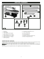
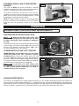
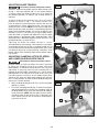
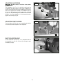
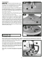
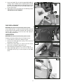
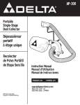
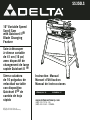
SS350LS 10" Contractors Saw (Model 36-978/36-979) 16" Variable Speed Scroll Saw with Quickset II® Blade Changing Feature Scie à découper $ELTA,OGO à vitesse variable0-3BLACK de 41 cm (16 po) 7HITELOGOWITHBLACK BACKGROUNDISTHEPRIMARY avec dispositif deUSEOFOURTRADEMARK7HEN SIZEOFLOGOFALLSBELOW ORTHEREISNOBLACKBACKGROUND changement de lame THENUSETHEBOTTOMLOGO ® rapide Quickset II4HISVERSIONOFTHETRADEMARKIS ONLYTOBEUSEDWHENTHEPRODUCT ISPRESENT Sierra caladora de 16 pulgadas de velocidad variable con dispositivo Quickset II® de cambio de hoja rápido A15112 -01-13-06 - Rev. A Copyright © 2006 Delta Machinery Instruction Manual Manuel d’Utilisation Manual de Instrucciones FRANÇAIS 19 ESPAÑOL 37 www.deltamachinery.com (800) 223-7278 - US (800) 463-3582 - CANADA TABLE OF CONTENTS IMPORTANT SAFETY INSTRUCTIONS . . . . . . . . . . . . . . . . . . . . . . . . . . . . . . . . . . . . . . . . . . . . . . . . . . . . . . . . . . . 2 safety guidelines - definitions . . . . . . . . . . . . . . . . . . . . . . . . . . . . . . . . . . . . . . . . . . . . . . . . . . . . . . . . . . . . 3 GENERAL SAFETY RULES . . . . . . . . . . . . . . . . . . . . . . . . . . . . . . . . . . . . . . . . . . . . . . . . . . . . . . . . . . . . . . . . . . . . . 4 ADDITIONAL SPECIFIC SAFETY RULES . . . . . . . . . . . . . . . . . . . . . . . . . . . . . . . . . . . . . . . . . . . . . . . . . . . . . . . . . . 5 FUNCTIONAL DESCRIPTION . . . . . . . . . . . . . . . . . . . . . . . . . . . . . . . . . . . . . . . . . . . . . . . . . . . . . . . . . . . . . . . . . . . 7 CARTON CONTENTS . . . . . . . . . . . . . . . . . . . . . . . . . . . . . . . . . . . . . . . . . . . . . . . . . . . . . . . . . . . . . . . . . . . . . . . . . 8 assembly . . . . . . . . . . . . . . . . . . . . . . . . . . . . . . . . . . . . . . . . . . . . . . . . . . . . . . . . . . . . . . . . . . . . . . . . . . . . . . . . . . 9 operation . . . . . . . . . . . . . . . . . . . . . . . . . . . . . . . . . . . . . . . . . . . . . . . . . . . . . . . . . . . . . . . . . . . . . . . . . . . . . . . . 10 TROUBLESHOOTING . . . . . . . . . . . . . . . . . . . . . . . . . . . . . . . . . . . . . . . . . . . . . . . . . . . . . . . . . . . . . . . . . . . . . . . . 15 MAINTENANCE . . . . . . . . . . . . . . . . . . . . . . . . . . . . . . . . . . . . . . . . . . . . . . . . . . . . . . . . . . . . . . . . . . . . . . . . . . . . . 15 SERVICE . . . . . . . . . . . . . . . . . . . . . . . . . . . . . . . . . . . . . . . . . . . . . . . . . . . . . . . . . . . . . . . . . . . . . . . . . . . . . . . . . . . 18 ACCESSORIES . . . . . . . . . . . . . . . . . . . . . . . . . . . . . . . . . . . . . . . . . . . . . . . . . . . . . . . . . . . . . . . . . . . . . . . . . . . . . . 18 WARRANTY . . . . . . . . . . . . . . . . . . . . . . . . . . . . . . . . . . . . . . . . . . . . . . . . . . . . . . . . . . . . . . . . . . . . . . . . . . . . . . . . 18 FranÇais . . . . . . . . . . . . . . . . . . . . . . . . . . . . . . . . . . . . . . . . . . . . . . . . . . . . . . . . . . . . . . . . . . . . . . . . . . . . . . . . . 19 ESPAÑOL . . . . . . . . . . . . . . . . . . . . . . . . . . . . . . . . . . . . . . . . . . . . . . . . . . . . . . . . . . . . . . . . . . . . . . . . . . . . . . . . . . 37 IMPORTANT SAFETY INSTRUCTIONS Read and understand all warnings and operating instructions before using any tool or equipment. When using tools or equipment, basic safety precautions should always be followed to reduce the risk of personal injury. Improper operation, maintenance or modification of tools or equipment could result in serious injury and property damage. There are certain applications for which tools and equipment are designed. Delta Machinery strongly recommends that this product NOT be modified and/or used for any application other than for which it was designed. If you have any questions relative to its application DO NOT use the product until you have written Delta Machinery and we have advised you. Online contact form at www.deltamachinery.com Postal Mail: Technical Service Manager Delta Machinery 4825 Highway 45 North Jackson, TN 38305 (IN CANADA: 125 Mural St. Suite 300, Richmond Hill, ON, L4B 1M4) Information regarding the safe and proper operation of this tool is available from the following sources: Power Tool Institute 1300 Sumner Avenue, Cleveland, OH 44115-2851 www.powertoolinstitute.org National Safety Council 1121 Spring Lake Drive, Itasca, IL 60143-3201 American National Standards Institute, 25 West 43rd Street, 4 floor, New York, NY 10036 www.ansi.org ANSI 01.1Safety Requirements for Woodworking Machines, and the U.S. Department of Labor regulations www.osha.gov SAVE THESE INSTRUCTIONS! safety guidelines - definitions It is important for you to read and understand this manual. The information it contains relates to protecting YOUR SAFETY and PREVENTING PROBLEMS. The symbols below are used to help you recognize this information. Indicates an imminently hazardous situation which, if not avoided, will result in death or serious injury. Indicates a potentially hazardous situation which, if not avoided, could result in death or serious injury. Indicates a potentially hazardous situation which, if not avoided, may result in minor or moderate injury. Used without the safety alert symbol indicates potentially hazardous situation which, if not avoided, may result in property damage. CALIFORNIA PROPOSITION 65 Some dust created by power sanding, sawing, grinding, drilling, and other construction activities contains chemicals known to cause cancer, birth defects or other reproductive harm. Some examples of these chemicals are: • lead from lead-based paints, • crystalline silica from bricks and cement and other masonry products, and • arsenic and chromium from chemically-treated lumber. Your risk from these exposures varies, depending on how often you do this type of work. To reduce your exposure to these chemicals: work in a well ventilated area, and work with approved safety equipment, always wear NIOSH/OSHA approved, properly fitting face mask or respirator when using such tools. GENERAL SAFETY RULES Failure to follow these rules may result in serious personal injury. 1. FOR YOUR OWN SAFETY, READ THE INSTRUCTION MANUAL BEFORE OPERATING THE MACHINE. Learning the machine’s application, limitations, and specific hazards will greatly minimize the possibility of accidents and injury. 2. WEAR EYE AND HEARING PROTECTION. ALWAYS USE SAFETY GLASSES. Everyday eyeglasses are NOT safety glasses. USE CERTIFIED SAFETY EQUIPMENT. Eye protection equipment should comply with ANSI Z87.1 standards. Hearing equipment should comply with ANSI S3.19 standards. 3. WEAR PROPER APPAREL. Do not wear loose clothing, gloves, neckties, rings, bracelets, or other jewelry which may get caught in moving parts. Nonslip protective footwear is recommended. Wear protective hair covering to contain long hair. 4. DO NOT USE THE MACHINE IN A DANGEROUS ENVIRONMENT. The use of power tools in damp or wet locations or in rain can cause shock or electrocution. Keep your work area well-lit to prevent tripping or placing arms, hands, and fingers in danger. 5. MAINTAIN ALL TOOLS AND MACHINES IN peak CONDITION. Keep tools sharp and clean for best and safest performance. Follow instructions for lubricating and changing accessories. Poorly maintained tools and machines can further damage the tool or machine and/or cause injury. 6. CHECK FOR DAMAGED PARTS. Before using the machine, check for any damaged parts. Check for alignment of moving parts, binding of moving parts, breakage of parts, and any other conditions that may affect its operation. A guard or any other part that is damaged should be properly repaired or replaced with Delta or factory authorized replacement parts. Damaged parts can cause further damage to the machine and/or injury. 7.KEEP THE WORK AREA CLEAN. Cluttered areas and benches invite accidents. 8.KEEP CHILDREN AND VISITORS AWAY. Your shop is a potentially dangerous environment. Children and visitors can be injured. 9. REDUCE THE RISK OF UNINTENTIONAL STARTING. Make sure that the switch is in the "OFF" position before plugging in the power cord. In the event of a power failure, move the switch to the "OFF" position. An accidental start-up can cause injury. Do not touch the plug’s metal prongs when unplugging or plugging in the cord. 10. USE THE GUARDS. Check to see that all guards are in place, secured, and working correctly to prevent injury. 11. REMOVE ADJUSTING KEYS AND WRENCHES BEFORE STARTING THE MACHINE. Tools, scrap pieces, and other debris can be thrown at high speed, causing injury. 12. USE THE RIGHT MACHINE. Don’t force a machine or an attachment to do a job for which it was not designed. Damage to the machine and/or injury may result. 13. USE RECOMMENDED ACCESSORIES. The use of accessories and attachments not recommended by Delta may cause damage to the machine or injury to the user. 14. USE THE PROPER EXTENSION CORD. Make sure your extension cord is in good condition. When using an extension cord, be sure to use one heavy enough to carry the current your product will draw. An undersized cord will cause a drop in line voltage, resulting in loss of power and overheating. See the Extension Cord Chart for the correct size depending on the cord length and nameplate ampere rating. If in doubt, use the next heavier gauge. The smaller the gauge number, the heavier the cord. 15. SECURE THE WORKPIECE. Use clamps or a vise to hold the workpiece when practical. Loss of control of a workpiece can cause injury. 16. FEED THE WORKPIECE AGAINST THE DIRECTION OF THE ROTATION OF THE BLADE, CUTTER, OR ABRASIVE SURFACE. Feeding it from the other direction will cause the workpiece to be thrown out at high speed. 17. DON’T FORCE THE WORKPIECE ON THE MACHINE. Damage to the machine and/or injury may result. 18. DON’T OVERREACH. Loss of balance can make you fall into a working machine, causing injury. 19. NEVER STAND ON THE MACHINE. Injury could occur if the tool tips, or if you accidentally contact the cutting tool. 20. NEVER LEAVE THE MACHINE RUNNING UNATTENDED. TURN THE POWER OFF. Don’t leave the machine until it comes to a complete stop. A child or visitor could be injured. 21. Turn the machine "OFF", and disconnect the machine from the power source before installing or removing accessories, changing cutters, adjusting or changing set-ups. When making repairs, be sure to lock the start switch in the "OFF" position. An accidental start-up can cause injury. 22. MAKE YOUR WORKSHOP CHILDPROOF WITH PADLOCKS, MASTER SWITCHES, OR BY REMOVING STARTER KEYS. The accidental start-up of a machine by a child or visitor could cause injury. 23. STAY ALERT, WATCH WHAT YOU ARE DOING, AND USE COMMON SENSE. DO NOT USE THE MACHINE WHEN YOU ARE TIRED OR UNDER THE INFLUENCE OF DRUGS, ALCOHOL, OR MEDICATION. A moment of inattention while operating power tools may result in injury. 24. Use of this tool can generate and disburse dust or other airborne particles, including wood dust, crystalline silica dust and asbestos dust. Direct particles away from face and body. Always operate tool in well ventilated area and provide for proper dust removal. Use dust collection system wherever possible. Exposure to the dust may cause serious and permanent respiratory or other injury, including silicosis (a serious lung disease), cancer, and death. Avoid breathing the dust, and avoid prolonged contact with dust. Allowing dust to get into your mouth or eyes, or lay on your skin may promote absorption of harmful material. Always use properly fitting NIOSH/OSHA approved respiratory protection appropriate for the dust exposure, and wash exposed areas with soap and water. ADDITIONAL SPECIFIC SAFETY RULES Failure to follow these rules may result in serious personal injury. 14. DO NOT CUT A WORKPIECE THAT DOES NOT HAVE A FLAT SURFACE against the table. 15. MAKE RELIEF CUTS before cutting long curves. Never attempt to cut a curve that is too tight. Breaking blades can cause injury. 16. NEVER BACK A BOUND BLADE OUT OF A KERF with the saw running. Turn the saw "OFF", disconnect the saw from the power source, wedge the kerf and remove the blade. Breaking blades can cause injury. 17. USE CAUTION WHEN CUTTING IRREGULAR WORKPIECES. This type of workpiece can pinch the blade before the cut is complete. Breaking blades can cause injury. 18. USE CAUTION WHEN CUTTING ROUND MATERIAL. This type of workpiece has a tendency to "roll" and can cause the blade to bite. Breaking blades can cause injury. 19. PROPERLY SUPPORT LONG OR WIDE workpieces. Loss of control of the workpiece can cause injury. 20. NEVER PERFORM LAYOUT, ASSEMBLY, OR SETUP WORK ON THE TABLE/WORK AREA WHEN THE MACHINE IS RUNNING. A sudden slip could cause a hand to move into the blade. Injury can result. 21. TURN THE MACHINE "OFF", disconnect the machine from the power source, and clean the table/ work area before leaving the machine. Lock the switch in the "OFF" position to prevent unauthorized use. Someone else might accidentally start the machine and cause injury to themselves. 22. ADDITIONAL INFORMATION regarding the safe and proper operation of power tools (i.e. a safety video) is available from the Power Tool Institute, 1300 Sumner Avenue, Cleveland, OH 44115-2851 (www.powertoolinstitute.com). Information is also available from the National Safety Council, 1121 Spring Lake Drive, Itasca, IL 60143-3201. Please refer to the American National Standards Institute ANSI 01.1 Safety Requirements for Woodworking Machines and the U.S. Department of Labor OSHA 1910.213 Regulations. 1. DO NOT OPERATE THIS MACHINE UNTIL IT IS COMPLETELY ASSEMBLED AND INSTALLED ACCORDING TO THE INSTRUCTIONS. A machine incorrectly assembled can cause serious injury. 2. OBTAIN ADVICE from your supervisor, instructor, or another qualified person if you are not thoroughly familiar with the operation of this machine. Knowledge is safety. 3. FOLLOW ALL WIRING CODES and recommended electrical connections to prevent shock or electrocution. 4. SECURE THE MACHINE TO A SUPPORTING SURFACE. Vibration can cause the machine to slide, walk, or tip over. 5. N E V E R S TA RT T H E M A C H I N E B E F O R E CLEARING THE TABLE of all objects (tools, scrap pieces, etc.). Debris can be thrown at high speed causing injury. 6. NEVER START THE MACHINE WITH THE WORKPIECE AGAINST THE BLADE. The workpiece can be thrown, causing injury. 7. NEVER START THE MACHINE UNTIL ALL HANDLES ARE LOCKED AND THE BLADE IS AT THE CORRECT TENSION. Abnormal operations cause injuries. 8. AVOID Awkward operations and hand positions. A sudden slip could cause a hand to move into the blade. 9.KEEP ARMS, HANDS, and fingers away from the blade to prevent injury. 10. NEVER REACH UNDER THE TABLE while the machine is running. A moving blade under the table can cause injury. 11. ADJUST THE "HOLD-DOWN" FOOT FOR EACH NEW OPERATION. Loss of control of the workpiece can cause injury. 12. HOLD THE WORKPIECE FIRMLY AGAINST THE TABLE. Loss of control of the workpiece can cause injury. 13. DO NOT CUT A WORKPIECE THAT IS TOO SMALL TO BE SAFELY SUPPORTED. When hands are too close to the blade, a wrong move can cause injury. SAVE THESE INSTRUCTIONS. Refer to them often and use them to instruct others. POWER CONNECTIONS A separate electrical circuit should be used for your machines. This circuit should not be less than #12 wire and should be protected with a 20 Amp time lag fuse. If an extension cord is used, use only 3-wire extension cords which have 3-prong grounding type plugs and matching receptacle which will accept the machine’s plug. Before connecting the machine to the power line, make sure the switch (s) is in the "OFF" position and be sure that the electric current is of the same characteristics as indicated on the machine. All line connections should make good contact. Running on low voltage will damage the machine. Do not expose the machine to rain or operate the machine in damp locations. MOTOR SPECIFICATIONS Your machine is wired for 120V, 60 HZ alternating current. Before connecting the machine to the power source, make sure the switch is in the "OFF" position. GROUNDING INSTRUCTIONS This machine must be grounded while in use to protect the operator from electric shock. 1. All grounded, cord-connected machines: In the event of a malfunction or breakdown, grounding provides a path of least resistance for electric current to reduce the risk of electric shock. This machine is equipped with an electric cord having an equipment-grounding conductor and a grounding plug. The plug must be plugged into a matching outlet that is properly installed and grounded in accordance with all local codes and ordinances. Do not modify the plug provided - if it will not fit the outlet, have the proper outlet installed by a qualified electrician. Improper connection of the equipment-grounding conduc-tor can result in risk of electric shock. The conductor with insulation having an outer surface that is green with or without yellow stripes is the equipment-grounding conductor. If repair or replacement of the electric cord or plug is necessary, do not connect the equipmentgrounding conductor to a live terminal. Check with a qualified electrician or service personnel if the grounding instructions are not completely understood, or if in doubt as to whether the machine is properly grounded. Use only 3-wire extension cords that have 3-prong grounding type plugs and matching 3-conductor receptacles that accept the machine’s plug, as shown in Fig. A. Repair or replace damaged or worn cord immediately. 2. Grounded, cord-connected machines intended for use on a supply circuit having a nominal rating less than 150 volts: If the machine is intended for use on a circuit that has an outlet that looks like the one illustrated in Fig. A, the machine will have a grounding plug that looks like the plug illustrated in Fig. A. A temporary adapter, which looks like the adapter illustrated in Fig. B, may be used to connect this plug to a matching 2-conductor receptacle as shown in Fig. B if a properly grounded outlet is not available. The temporary adapter should be used only until a properly grounded outlet can be installed by a qualified electrician. The green-colored rigid ear, lug, and the like, extending from the adapter must be connected to a permanent ground such as a properly grounded outlet box. Whenever the adapter is used, it must be held in place with a metal screw. NOTE: In Canada, the use of a temporary adapter is not permitted by the Canadian Electric Code. In all cases, make certain that the receptacle in question is properly grounded. If you are not sure, have a qualified electrician check the receptacle. GROUNDED OUTLET BOX GROUNDED OUTLET BOX GROUNDING MEANS CURRENT CARRYING PRONGS ADAPTER GROUNDING BLADE IS LONGEST OF THE 3 BLADES Fig. A Fig. B EXTENSION CORDS MINIMUM GAUGE EXTENSION CORD Use proper extension cords. Make sure your extension cord is in good condition and is a 3-wire extension cord which has a 3-prong grounding type plug and matching receptacle which will accept the machine’s plug. When using an extension cord, be sure to use one heavy enough to carry the current of the machine. An undersized cord will cause a drop in line voltage, resulting in loss of power and overheating. Fig. D-1 or D-2, shows the correct gauge to use depending on the cord length. If in doubt, use the next heavier gauge. The smaller the gauge number, the heavier the cord. RECOMMENDED SIZES FOR USE WITH STATIONARY ELECTRIC MACHINES Ampere Rating 0-6 0-6 0-6 0-6 6-10 6-10 6-10 6-10 10-12 10-12 10-12 10-12 12-16 12-16 12-16 Volts 120 120 120 120 120 120 120 120 120 120 120 120 120 120 120 Total Length of Cord in Feet up to 25 25-50 50-100 100-150 up to 25 25-50 50-100 100-150 up to 25 25-50 50-100 100-150 up to 25 25-50 Gauge of Extension Cord 18 AWG 16 AWG 16 AWG 14 AWG 18 AWG 16 AWG 14 AWG 12 AWG 16 AWG 16 AWG 14 AWG 12 AWG 14 AWG 12 AWG greater than 50 feet not recommended Fig. D-1 FUNCTIONAL DESCRIPTION FOREWORD The Delta SS350LS 16" Scroll Saw is designed to give high quality, smooth cutting performance with capacity to cut up to 16" wide by 2" thick woodworking materials and have a 3/4" stroke. The Delta SS350LS comes equipped with integral dust port; a stand; variable speed at 600-1650 cutting strokes per minute; lockout switch; cast iron table for minimal vibration; Quickset II® Blade Chuck System for ergonomic "wrench-free" blade changing; accepts wide variety of 5" flat end blades; 45° left tilting for bevel cuts and adjustable dust blower to keep cutting line free of dust. NOTICE: The photo on the manual cover illustrates the current production model. All other illustrations contained in the manual are representative only and may not depict the actual labeling or accessories included. These are intended to illustrate technique only. CARTON CONTENTS 2 3 4 5 6 1 7 9 8 11 10 13 12 Fig. 1 1. 2. 3. 4. 5. 6. 7. Scroll Saw Stand Leg (3) Lower Side Brace 30" Long (2) Upper Side Brace 22½" Long (2) Lower Back Brace 18½" Long (1) Upper Back Brace 12" Long (1) Stand Leg Foot (3) 8. 5/16-18x1½" Hex Head Screw (3) 9. 5/16" Flat Washer (6) 10. 5/16" Lockwasher (3) 11. 5/16-18 Hex Nut (3) 12. M8x16mm Carriage Head Screw (12) 13 M8x1.25 Flange Hex Nut (12) UNPACKING AND CLEANING Carefully unpack the machine and all loose items from the shipping container(s). Remove the rust-preventative oil from unpainted surfaces using a soft cloth moistened with mineral spirits, paint thinner or denatured alcohol. machine. Do not use highly volatile solvents such as gasoline, naphtha, acetone or lacquer thinner for cleaning your After cleaning, cover the unpainted surfaces with a good quality household floor paste wax. assembly For your own safety, do not connect the machine to the power source until the machine is completely assembled and you read and understand the entire instruction manual. ASSEMBLY TOOLS REQUIRED 1/2" and 13mm wrenches (not supplied) ASSEMBLY TIME ESTIMATE Assembly takes approximately 30 minutes to 1 hour. STAND NOTE: THE ASSEMBLY OF THIS STAND WILL USE M8X16MM CARRIAGE HEAD SCREWS AND M8 FLANGED HEX NUTS. KEEP THE HEAD OF THE CARRIAGE HEAD SCREWS TO THE OUTSIDE OF THE STAND WITH THE FLANGED HEX NUTS TO THE INSIDE OF THE STAND. 6 Fig. 2 4 4 NOTE: MAKE SURE THAT THE SHELF ON THE BRACES ARE ON TOP WHEN ATTACHING THE BRACES TO THE LEGS. 2 2 5 3 Assemble stand as shown in Fig. 2 using parts shown in Fig. 1. The braces, legs and feet are labeled the same in both illustrations. Insert the M8x1.25x16mm carriage head screws through legs and braces then secure with the M8x1.25 flange hex nuts. Loosely tighten hardware at this time. NOTE: MAKE SURE THAT THE DIMPLES ON THE LEGS (A) FIG. 2 ARE ENGAGED WITH THE HOLES ON THE BRACES (B). Fig. 2 7 3 7 A B SCROLL SAW TO STAND 1. Place the scroll saw on the top braces of the stand Fig. 3. 2. Align the three holes (A) Fig. 3, (two of which are shown), with the three holes in the top of the stand. 3. Place a 5/16" flat washer on a 5/16-18x1½" hex head screw, insert the screw through the hole in the base of the scroll saw and the hole in the stand. Place a 5/16" flat washer, 5/16" lockwasher and thread a 5/16-18 hex nut onto the screw. Repeat this process for the two remaining holes in the scroll saw base and stand. 4. Tighten all stand hardware securely. Fig. 3 A A FASTENING SCROLL SAW TO SUPPORTING SURFACE Fig. 4 This scroll saw MUST be securely fastened to a stand or workbench using the three holes, two of which are shown at (A) Fig. 4. The third hole is at the rear of the machine. An alternate method of securing the scroll saw to a supporting surface is to fasten the scroll saw to a mounting board. Then securely clamp the mounting board to a stand or workbench using two or more C-clamps. NOTE: For proper stability, the holes in the mounting board must be countersunk at the bottom so that the fastener heads are flush with the bottom surface of the mounting board. A operation OPERATIONAL Controls and ADJUSTMENTS STARTING AND STOPPING SCROLL SAW Make sure that the switch is in the "OFF" position before plugging cord into outlet. Do not touch the plug’s metal prongs when unplugging or plugging in the cord. The on/off switch (A) Fig. 5 is located on the right side of the scroll saw base. To turn the machine "ON", move the switch up to the "ON" position. To turn the machine "OFF", move the switch (A) down to the "OFF" position. Fig. 5 B LOCKING SWITCH IN THE "OFF" POSITION A IMPORTANT: When the machine is not in use, the switch should be locked in the "OFF" position to prevent unauthorized use. To lock the machine, grasp the switch toggle (B) and pull it out of the switch (Fig. 6). With the switch toggle (B) removed, the switch will not operate. Fig. 6 However, should the switch toggle be removed while the saw is running, the machine can be turned "OFF," but cannot be restarted without re-inserting the switch toggle (B). In the event of a power outage (such as a breaker or fuse trip), always move the switch to the "OFF" position until the main power is restored. An accidental start-up can cause injury. B VARIABLE SPEED SWITCH The scroll saw is equipped with a variable speed control (B) Fig. 5. The variable speed range is 600 to 1650 strokes per minute. When the variable speed knob (B) Fig. 5, is rotated all the way to the left (counterclockwise) the speed will be 600 strokes per minute. To increase the speed, rotate knob (B) to the right (clockwise) until the desired speed is obtained. When the knob (B) is rotated all the way to the right (clockwise) the speed will be 1650 strokes per minute. 10 ADJUSTING BLADE TENSION Disconnect machine from power source. Fig. 7 Tension is applied to the blade when the blade tension lever (A) Fig. 7, has been adjusted and is in the vertical position as shown. When the blade tension lever (A) is moved to the horizontal position, as shown in Fig. 8, blade tension is released. A To adjust blade tension, position lever (A) in the vertical position, as shown in Fig. 7. To increase tension, turn lever (A) clockwise and to decrease tension turn lever (A) counterclockwise. When adjusting tension, turn lever onequarter of a turn at a time. NOTE: It is necessary to adjust the blade tension only when the blade is removed from both the upper and lower blade holders and a new or different type of blade is used. It is not necessary to adjust blade tension when the blade is removed and replaced in only the upper blade holder as in performing inside cutting operations. After desired tension is obtained, position tension lever (A) in the horizontal position, as shown in Fig. 7. Adjusting the blade for proper tension is usually accomplished by trial and error. One method is to pull back on the blade tension lever (A) Fig. 8, the blade should start to have tension (resistance) when the blade tension lever is half way between open Fig. 8, and closed Fig. 7 positions. Finer blades require more tensioning while thicker blades require less tension. Fig. 8 ADJUSTING CLAMPING ACTION OF UPPER AND LOWER BLADE HOLDER CHUCK Disconnect machine from power source. Different widths of scroll saw blades will make it necessary to adjust the clamping action of the upper and lower blade holders. It should be noted, however, that very little adjustment is necessary and very little clamping force is required to hold the blade satisfactorily. As a rule of thumb, looking down at the table with the table insert slot in the 6 o’clock position, resistance on the blade locking lever should be felt when the upper blade locking lever reaches the 7 o’clock position, or when the lower blade locking lever reaches the 5 o’clock position. 1. Move the blade locking lever (A) Fig. 9, to the rear (open) position, as shown. 2. Turn chuck clamping knob (B) Fig. 9, clockwise to tighten and counterclockwise to loosen the clamping action of the blade holder chuck. Very little movement of knob (B) will be necessary. NOTE: Only the upper chuck is shown. Clamping action of the lower chuck is adjusted in the same manner and can be accessed by removing dust cup shown in Fig. 24. 11 A Fig. 9 B A TILTING THE TABLE Disconnect machine from power source. Fig. 10 The table on your scroll saw can be tilted 45° to the left for bevel cutting operations by removing the dust cup as shown in Fig. 24 and loosening table lock knob (A) Fig. 10, tilt the table to the desired angle indicated on degree scale (B) Fig. 11 and tighten lock handle (A) Fig. 10. When bevel cutting, the holddown (B) Fig. 12, can be adjusted to lay flat on the stock by loosening screw (C) and tilting the holddown (B). Then tighten screw (C). A ADJUSTING THE TABLE Disconnect machine from power source. 1. Loosen table lock knob as shown in Fig. 10 and move the table all the way to the right until angle indicator shown in Fig. 11 is on "0". 2. Using a square that includes a level, check to see if the table is level (A) Fig. 13, and is 90° to the saw blade (B), as shown. 3. If the table is not at 90° to the blade, adjust the table making certain screw (B) Fig. 14, contacts bottom of table surface when table is 90° to the blade. To make this adjustment loosen nut (C), turn screw (B) in or out the desired distance and tighten nut (C). NOTE: After adjusting table, reposition the pointer (B) Fig. 11 to "0" degrees. Loosen the screw (A) Fig. 11 and adjust pointer (B) to "0" degree mark and retighten screw (A). Fig. 11 A B Fig. 12 C B Fig. 13 Fig. 14 B B C A 12 ADJUSTING HOLDDOWN source. Fig. 15 Disconnect machine from power B The holddown (A) Fig. 15, should be adjusted so it contacts the top surface of the work (D) being cut. Loosen lock knob (B) and move holddown rod (C) up or down, then tighten lock knob (B). The holddown (A) Fig. 15, may be adjusted front to rear, by loosening set screw (B) Fig. 16, and positioning the holddown in the desired location. Once the holddown is in the desired location, tighten set screw (B), Fig. 16. C A D ADJUSTING DUST BLOWER Fig. 16 The dust blower (A) Fig. 16, may be positioned to direct air to the most effective point on the workpiece. B A DUST COLLECTION CUP Fig. 17 A dust collection cup (A) Fig. 17 is provided and can be attached to a vacuum system by utilizing the port covered by cap (B). A B 13 TABLE INSERT Fig. 18 Disconnect machine from power source. The table insert (A) can be positioned in the saw table with the opening in the insert pointing to the front of the table, as shown in Fig. 18, or to the right as shown in Fig. 19. With the table in the level position, 90° to the blade, the insert (A) should be positioned, as shown in Fig. 18. This allows for the blade to be pivoted forward after it is unclamped from the top blade holder, enabling you to quickly insert the blade into the next hole in a pattern when doing inside-cutting, as you will see later in this manual. When tilting the table for bevel cutting operations the insert (A) should be positioned as shown in Fig. 19. This allows for clearance of the blade when tilting the table. A Fig. 19 A blank table insert (B) Fig. 20, is supplied as standard equipment with your scroll saw and can be used when cutting very small workpieces to give added support to the bottom of the workpiece. Cut a slot into the blank and replace the standard insert (A) with the blank (B). The slot cut into the blank (B) will only be as wide as the blade giving maximum support to the bottom of the workpiece. Adhesive backed spacer pads (C) are also supplied for adjusting the table insert height relative to the table surface. Place three pads an equal distance apart on a cleaned surface to be applied to the blank insert. Pads can be stacked in order to achieve desired insert height. A Fig. 20 B A C MACHINE USE FOLLOWING A LINE With your scroll saw you should be able to perform straight or curved cuts with ease. Most beginners will experience blade wandering; however, they eventually learn to control it as they become more familiar with the machine. Use scrap material to practice cuts before starting a project. This enables you to develop your own style of cutting and you will Fig. 21 discover what you can do with your saw. Always hold the work firmly against the table and do not feed the workpiece too fast while cutting. Feed the workpiece only fast enough so that the blade will cut. Scroll saws cut faster across the grain than they do with the grain. Allow for this tendency when cutting patterns that shift rather quickly from with-the-grain cuts to cross-grain cuts. Make "relief" cuts before cutting long curves and never attempt to cut a curve that is too tight for the blade being used. C A D E B 14 INSIDE CUTTING Inside cutting takes place when the blade is threaded through a hole in the workpiece. With your scroll saw, you can perform this operation quickly and easily as follows: Loosen lock handle (A) Fig. 21, and raise the holddown (B). Release blade tension by moving the blade tension lever (C) to the horizontal position as previously explained. Release upper blade holder lever (D) as previously explained. This will release the blade (E) and allow you to thread the blade through the next hole in the pattern. Replace blade in upper blade holder and move blade tension lever to the vertical position to reapply blade tension. Lower holddown and you are ready to make the next cut. TROUBLESHOOTING For assistance with your machine, visit our website at www.deltamachinery.com for a list of service centers or call the DELTA Machinery help line at 1-800-223-7278 (In Canada call 1-800-463-3582). CHOICE OF BLADE AND SPEED Your scroll saw will accept a wide variety of 5" flat end blades and can be operated at any speed from 600 to 1650 cutting strokes per minute. Consider the following as a general guideline for selecting a blade and operating speed. 1. Use a finer blade for cutting thin workpieces, for hard materials, or when a smooth cut is required. 2. Use a coarser blade for cutting thick workpieces, when making straight cuts or for medium to soft materials. 3. Use a blade that will have 2 teeth in the workpiece at all times. 4. Most blade packaging is marked with the size of the wood the blade is intended to cut and the minimum radius which can be cut with that blade. 5. Slower speeds are generally more effective than faster speeds when using thin blades and making intricate cuts. 6. Always start at a slow speed and gradually increase the speed until the best cutting speed is obtained. BLADE BREAKAGE Blade breakage is usually caused by one or more of the following: 1. Bending the blade during installation. 2. Improper blade tension. 3. Improper blade selection for the work being cut. 4. Forcing the work into the blade too rapidly. 5. Cutting too sharp a turn for the blade being used. 6. Improper blade speed. MAINTENANCE KEEP MACHINE CLEAN Periodically blow out all air passages with dry compressed air. All plastic parts should be cleaned with a soft damp cloth. NEVER use solvents to clean plastic parts. They could possibly dissolve or otherwise damage the material. Wear certified safety equipment for eye, hearing and respiratory protection while using compressed air. FAILURE TO START Should your machine fail to start, check to make sure the prongs on the cord plug are making good contact in the outlet. Also, check for blown fuses or open circuit breakers in the line. LUBRICATION & RUST PROTECTION Apply household floor paste wax to the machine table, extension table or other work surface weekly. Or use a commercially available protective product designed for this purpose. Follow the manufacturer’s instructions for use and safety. To clean cast iron tables of rust, you will need the following materials: a sheet of medium Scotch-Brite™ Blending Hand Pad, a can of WD-40® and a can of degreaser. Apply the WD-40 and polish the table surface with the Scotch-Brite pad. Degrease the table, then apply the protective product as described above. 15 CHANGING BLADES Disconnect machine from power source. 1. Remove table insert (A) Fig. 22, and release blade tension by pulling tension lever (B) forward, as shown. Fig. 22 B A 2. Push upper blade chuck locking lever (C) Fig. 23, to the rear as shown. This will release the blade (D) from the upper chuck (E). Fig. 23 E C D 3. Remove the dust collection cup (A) by rotating knob (B) 90° as shown in Fig. 24. Slide dust cup out of the guides (C) by pulling it toward the front. NOTE: DO NOT OPERATE THE UNIT WITH THE DUST CUP REMOVED. Fig. 24 B A 4. Push lower blade chuck locking lever (F) Fig. 25, to the rear as shown. This will release the blade (G) from the lower chuck (H). Fig. 25 H G F 16 5. Insert new blade (I) Fig. 26, into the upper blade holder (J) making certain the blade teeth are pointing down toward the table. Push upper blade chuck locking lever (L) to the front. Insert new blade into the lower blade holder Fig. 25 in the same manner. 6. Apply blade tension by referring to the following section "ADJUSTING BLADE TENSION." Fig. 26 J I L FUSE REPLACEMENT Fig. 27 WARNING: Disconnect machine from power source. A fuse holder (A) Fig. 27, and fuse (B) are located at the rear of the machine and should be removed and checked if the machine does not operate. If the fuse (B) is bad, replace it with a 3 amp fast blow fuse. B LUBRICATION WARNING: Disconnect machine from power source. Perform maintenance below after each 20 hours of use. 1. Tilt the table 45° to the left as shown in Fig. 28. 2. Remove four rubber grommets (A) Fig. 29 that cover the lubrication access holes. 3. Lubricate the pivot points in each of the four access holes with a few drops of light machine oil. 4. Reassemble the four grommets as shown in Fig. 29. 5. Apply lightweight grease or anti-seize to lubricate the tensioning lever (C) Fig. 21 where it pivots on the upper chuck. A Fig. 28 Fig. 29 A 17 SERVICE REPLACEMENT PARTS Service Center, visit our website at www.deltamachinery. com or call our Customer Care Center at 1-800-223-7278. All repairs made by our service centers are fully guaranteed against defective material and workmanship. We cannot guarantee repairs made or attempted by others. Use only identical replacement parts. For a parts list or to order parts, visit our website at servicenet.deltamachinery. com. You can also order parts from your nearest factoryowned branch, or by calling our Customer Care Center at 1-800-223-7278 to receive personalized support from highlytrained technicians. You can also write to us for information at Delta Machinery, 4825 Highway 45 North, Jackson, Tennessee 38305 Attention: Product Service. Be sure to include all of the information shown on the nameplate of your tool (model number, type, serial number, etc.) SERVICE AND REPAIRS All quality tools will eventually require servicing and/or replacement of parts. For information about Delta Machinery, its factory-owned branches, or an Authorized Warranty ACCESSORIES A complete line of accessories is available from your Delta Supplier, Porter-Cable • Delta Factory Service Centers, and Delta Authorized Service Stations. Please visit our Web Site www.deltamachinery.com for a catalog or for the name of your nearest supplier. Since accessories other than those offered by Delta have not been tested with this product, use of such accessories could be hazardous. For safest operation, only Delta recommended accessories should be used with this product. WARRANTY To register your tool for warranty service visit our website at www.deltamachinery.com. Two Year Limited New Product Warranty Delta will repair or replace, at its expense and at its option, any new Delta machine, machine part, or machine accessory which in normal use has proven to be defective in workmanship or material, provided that the customer returns the product prepaid to a Delta factory service center or authorized service station with proof of purchase of the product within two years and provides Delta with reasonable opportunity to verify the alleged defect by inspection. For all refurbished Delta product, the warranty period is 180 days. Delta may require that electric motors be returned prepaid to a motor manufacturer’s authorized station for inspection and repair or replacement. Delta will not be responsible for any asserted defect which has resulted from normal wear, misuse, abuse or repair or alteration made or specifically authorized by anyone other than an authorized Delta service facility or representative. Under no circumstances will Delta be liable for incidental or consequential damages resulting from defective products. This warranty is Delta’s sole warranty and sets forth the customer’s exclusive remedy, with respect to defective products; all other warranties, express or implied, whether of merchantability, fitness for purpose, or otherwise, are expressly disclaimed by Delta. 18 The following are trademarks of PORTER-CABLE • DELTA (Las siguientes son marcas registradas de PORTER-CABLE • DELTA S.A.) (Les marques suivantes sont des marques de fabriquant de la PORTER-CABLE • DELTA): Auto-Set®, BAMMER®, B.O.S.S.®, Builder’s Saw®, Contractor’s Saw®, Contractor’s Saw II™, Delta®, DELTACRAFT®, DELTAGRAM™, Delta Series 2000™, DURATRONIC™, Emc²™, FLEX®, Flying Chips™, FRAME SAW®, Grip Vac™, Homecraft®, Jet-Lock®, JETSTREAM®, ‘kickstand®, LASERLOC®, MICRO-SET®, Micro-Set®, MIDI LATHE®, MORTEN™, NETWORK™, OMNIJIG®, POCKET CUTTER®, PORTA-BAND®, PORTA-PLANE®, PORTER-CABLE®&(design), PORTER-CABLE®PROFESSIONAL POWER TOOLS, PORTER-CABLE REDEFINING PERFORMANCE™, Posi-Matic®, Q-3®&(design), QUICKSAND®&(design), QUICKSET™, QUICKSET II®, QUICKSET PLUS™, RIPTIDE™&(design), SAFE GUARD II®, SAFE-LOC®, Sanding Center®, SANDTRAP®&(design), SAW BOSS®, Sawbuck™, Sidekick®, SPEED-BLOC®, SPEEDMATIC®, SPEEDTRONIC®, STAIR EASE®, The American Woodshop®&(design), The Lumber Company®&(design), THE PROFESSIONAL EDGE®, THE PROFESSIONAL SELECT®, THIN-LINE™, TIGER®, TIGER CUB®, TIGER SAW®, TORQBUSTER®, TORQ-BUSTER®, TRU-MATCH™, TWIN-LITE®, UNIGUARD®, Unifence®, UNIFEEDER™, Unihead®, Uniplane™, Unirip®, Unisaw®, Univise®, Versa-Feeder®, VERSA-PLANE® , WHISPER SERIES®,WOODWORKER’S CHOICE™. Trademarks noted with ™ and ® are registered in the United States Patent and Trademark Office and may also be registered in other countries. Las Marcas Registradas con el signo de ™ y ® son registradas por la Oficina de Registros y Patentes de los Estados Unidos y también pueden estar registradas en otros países. Marques déposées, indiquées par la lettre ™ et ®, sont déposées au Bureau des brevets d’invention et marques déposées aux Etats-Unis et pourraient être déposées aux autres pays. Delta Machinery 4825 Highway 45 North Jackson, TN 38305 www.deltamachinery.com