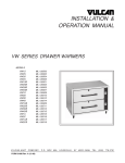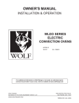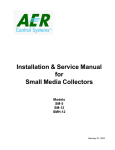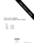
1
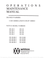
OPERATIONS
MAINTENANCE
MANUAL
DRAWER WARMERS
CAFE SERTES & RESTAURANT SERTES
WITTCO MODEL NUMBERS
200-1R-C
200-2R-C
200-3R-C
200-4R-C
200-iR
200- 1R-BI-C
200-2R-BI-C
200-3R-BI-C
200-4R-BI-C
200-1 R-BI
200-2R
200-3R
200-4R
A
200-2R-BI
200-3R-BI
200-4R-BI
i
wittco
foodservice
equipment
F-4101 b
F-41015
PDF compression, OCR, web optimization using a watermarked evaluation copy of CVISION PDFCompressor
PDF compression, OCR, web optimization using a watermarked evaluation copy of CVISION PDFCompressor
LIMITED WARRANTY
Wittco warrants the Products that it manufactures to be free from defects in materials and
workmanship, under normal use and service, for the periods indicated below from the date of purchase
when installed and maintained in accordance with Wittco's written instructions. Buyer must establish
the "Products" purchase date by returning Wittco's Warranty registration Card or by other means
satisfactory to Wittco in its sole discretion.
Wittco warrants its Products to be free from defects in materials and workmanship from the date of
purchase (subject to the foregoing conditions) for the period(s) of time and on the conditions listed
below:
Ninety (90) days Labor Warranty
One (1) Year Parts Warranty
THE FOREGOING WARRANTIES ARE EXCLUSIVE AND IN LIEU OF ANY OTHER WARRANTY,
EXPRESSED OR IMPLIED, INCLUDING BUT NOT LIMITED TO ANY IMPLIED WARRANTY OF
MERCHANTABILITY OR FITNESS FOR A PARTICULAR PURPOSE OR PATENT OR OTHER
INTELLECTUAL PROPERTY RIGHT INFRINGEMENT. Without limiting the generality of the foregoing,
SUCH WARRANTIES DO NOT COVER: Coated incandescent light bulbs or heat lamps, all glass
components, Product misuse, tampering, misapplication, application of improper voltage, or
recalibration of thermostats or high limit switches.
LIMITATION OF REMEDIES & DAMAGES
Wittco's liability and Buyer's exclusive remedy hereunder will be limited solely, at Wittco's option, to
repair or replacement by a Wittco authorized service agency (other than where Buyer is located outside
of the United States or Canada, in which case Wittco's liability and Buyer's exclusive remedy
hereunder will be limited solely to replacement of part under warranty) with respect to any claim made
within the applicable warranty period referred to above.
Without limiting the generality of the
foregoing, all portable Products, as defined by Wittco, shall be delivered by Buyer, at its sole expense,
to the nearest Wittco authorized service agency for replacement or repair. Wittco reserves the right
to accept or reject any such claim in whole or in part. Wittco will not accept the return of any Product
without prior written approval from Wittco, and all such approved returns shall be made at Buyer's sole
expense. WITTCO WILL NOT BE LIABLE. UNDER ANY CIRCUMSTANCES. FOR CONSEQUENTIAL OR
INCIDENTAL DAMAGES, INCLUDING BUT NOT LIMITED TO LABOR COSTS OR LOST OF PRODUCTS
AND LOSS OF PROFITS RESULTING FROM THE USE OF OR INABILITY TO USE THE PRODUCTS.
wîttco
iA
foodservice
equipment
PDF compression, OCR, web optimization using a watermarked evaluation copy of CVISION PDFCompressor
WITTCO TECHNICAL & PRODUCT SUPPORT
TECHNICAL SUPPORT & SERVICE INQUIRES MAY BE DIRECTED TO WITTCO BY:
CALLING DIRECTLY TO:
WITTCO FOODSERVICE EQUIPMENT TECHNICAL & SERVICE DEPARTMENT - (800)
367-8413
8:00 AM - 4:30 PM (CENTRAL TIME)
FAXING DIRECTLY TO:
WITTCO FOODSERVICE EQUIPMENT TECHNICAL & SERVICE DEPARTMENT - (414)
354-2821
DAILY 24 HOURS
MAILING DIRECTLY TO:
WITTCO FOODSERVICE EQUIPMENT INC.
7737 NORTH 81ST. STREET
MILWAUKEE, WISCONSIN 53223
USA
WHEN DIRECTING INQUIRIES TO WITTCO PLEASE HAVE THE FOLLOWING INFORMATION
AVAILABLE TO AVOID DELAYS
Wittco model number indicated on the equipment serial data plate located at the
electrical connection.
Wittco serial number indicated on the equipment serial data plate. The equipment
serial number will also have two (2) alpha characters immediately following the serial
number. These alpha characters are part of the serial
number.
wïttca
p
AA
foodservice
equipment
PDF compression, OCR, web optimization using a watermarked evaluation copy of CVISION PDFCompressor
INTRODUCTION
The 200 series of drawer warmers from Wittco Foodservice Equipment provide an efficient and
sanitary method of holding a variety of hot prepared foods.
This manual has been produced to provide persons responsible for the operation and maintenance
of the equipment with a simple but comprehensive understanding of its proper use and care. We
recommend that this manual be read and understood prior to placing the unit into operation.
NOTE:
THE DRAWER WARMER SHOULD BE THOROUGHLY CLEANED IN
ACCORDANCE WITH THE INSTRUCTIONS CONTAINED IN THIS
MANUAL PRIOR TO PUTTING INTO SERVICE.
It is recommended that prior to placing the drawer warmer into operation that it be pre-heated
at the highest temperature setting for period of 30-45 minutes.
Should repair or adjustment of the unit become necessary, we suggest that procedures described
in this manual be followed. The operator may also contact the authorized Wittco dealer who
sold the product or an authorized Wittco service agency. If the needed repair occurs during the
warranty period, prior authorization is required from Wittco by the service company before the
work is commenced.
It is our sincere desire that you obtain the maximum benefit from your Wittco heated drawer
warmer system. If at any time questions arise or additional information is required, contact
Wittco ar 800 367-8413.
DESCRIPTION
The Wittco 200 series of drawer warmers provide an efficient means of holding a variety of
prepared hot food products at proper temperatures until serving. The 200-R series is provided
with a large 15 X 20 over-sized drawer insert and the 200-C series with a standard
12 X 20 X 4 steam table pan insert.
UNCRATING
Each Wittco drawer warmer system is packed in a cardboard carton, which in turn is banded to
a wooden pallets. When the unit is received by the operator, the carton should immediately be
inspected for any sign of visible exterior damage to the carton. If the carton is punctured or
dented, it many be an indication that the unit has sustained concealed freight damage.
It is very important that any evidence of damage be noted on the Bill of Lading at the time
of receipt.
-1-
PDF compression, OCR, web optimization using a watermarked evaluation copy of CVISION PDFCompressor
UNPACKING THE UNIT
7
Remove the banding material holding the carton to the pallet.
Remove the cardboard carton and the plastic bag covering the unit.
Carefully lift the unit off the carton bottom and pallet and place it on the floor or table.
Remove the legs for the unit located in the drawer of the unit.
Secure the legs to the bottom of the drawer warmer by screwing the legs into the holes
provided.
Remove any and all packaging materials in the drawers.
Thoroughly clean the unit as described in the instructions.
ELECTRICAL REQUIREMENTS
The 200 drawer warmer series are factory wired for either 110/120 volt or 208/240 volt, single
phase operation. All 110/120 volt units are equipped with a 6 foot cord and NEMA 5-15 plug
as standard equipment. All 208/240 volt units are equipped with a 6 foot cord and NEMA 5-15
plug (200-iR & 1C; 200-2R & 2C; 200-3R & 3C) and a NEMA 6-20 plug (200-4R & 4C)
CAUTION: Verify that the power source matches the data plate on the lower rear corner
of the unit and the plug configuration before the connection is made.
OPERATION
The control panel of the 200 series contains an operating indicator light and full range
thermostat.
Once the unit has been connected to the appropriate power source the unit is ready for operation.
the operating thermostat also acts as the on/off switch to the drawer warmer system. Turning
the thermostat counter clock-wise until it stops will turn the system off.
Rotate the thermostat dial so that it points to the number 5. This will cause the heating elements
to start heating. When this occurs the red operating indicator light will illuminate, this light
will stay on as long as the heating element are engaged. Once the predetermined temperature
is achieved, the heating element will begin to cycle. During this period the red operating
indicator light will turn on and off as the heating elements cycle.
As the heating elements are heating, the thermometer will begin to move and indicate the interior
temperature of the cabinet. At the number 5 setting the thermometer should indicate an average
temperature of approximately 150 degrees F.
NOTE: The temperature in any heated unit will fluctuate as the heating element cycle on
and off. The thermostat setting will provide an average temperature in the unit. However,
the operator should always monitor the food product to insure that it remains at proper
temperatures.
2
PDF compression, OCR, web optimization using a watermarked evaluation copy of CVISION PDFCompressor
REMEMBER - THE GREATER THE THERMOSTAT NUMBER SETTING THE
HIGHER THE UNIT TEMPERATURE AN1 THE LOWER THE THERMOSTAT
NUMBER SETTING THE LOWER THE CABINET TEMPERATURE.
CLEANING
The interior drawer inserts of the unit should be cleaned prior to putting unit into service. Use
a mild soap and water solution to clean. Never use harsh chemicals or abrasive pads to clean
the unit.
REPLACEMENT OF ELECTRICAL COMPONENTS
It is highly recommended that only Wittco Foodservice Equipment replacement parts be used
to insure compatibility of component parts in the operation of the drawer warmer system.
THERMOSTAT/SENSING BULB REPLACEMENT
DISCONNECT THE UNIT FROM ITS POWER SOURCE.
Remove the black thermostat control knob from the control panel by loosening the "Lend" screws that hold it to the thermostat stem.
NOTE: PRIOR TO LOOSENING THE '1-END" SCREWS, TURN THE BLACK
THERMOSTAT KNOB SO THAT THE ARROW ON THE KNOB IS IN THE "OFF"
POSITION.
Remove the control panel from its housing by removing the control panel retaining
screws and gently pulling the control panel forward exposing the back side of the control
panel.
Notice the arrangement and connection of all electrical leads and refer to the wiring
diagrams for reference.
Disconnect the wire leads connected to the thermostat.
Remove the entire drawer from the unit exposing the temperature sensing bulb..
Loosen the screws holding the temperature sensing bulb to the interior drawer
compartment.
NOTE: The temperature sensing bulb must be replaced whenever the thermostat is
replaced. The temperature sensing bulb lead wire is permanently connected to the
thermostat.
Remove the screws holding the thermostat to the control panel.
-3-
PDF compression, OCR, web optimization using a watermarked evaluation copy of CVISION PDFCompressor
Gently pull the temperature sensing bulb lead wire through the access hole and remove
entire thermostat.
Install the replacement thermostat and temperature sensing bulb following the reverse
order of the above procedure.
Reinstall the control panel to the unit.
Reconnect the unit to its power source and test.
HEATING ELEMENT REPLACEMENT
DISCONNECT ThE UNIT FROM ITS POWER SOURCE.
Remove the entire drawer from the unit exposing the heating element.
Remove the element retaining screws securing the element to the floor of the drawer
compartment.
Remove the element retaining screws securing the element housing to the rear of the
drawer compartment.
Gently pull the element from its housing exposing the heated element wire connectors.
Disconnect the element connectors.
Install the replacement heating element following the reverse of the above steps.
Reinstall the drawer to its compartment by following the revere of the above.
Reconnect the unit to its power source and test.
INDICATOR LIGHT REPLACEMENT
DISCONNECT THE UNIT FROM ITS POWER SOURCE.
Remove the retaining screws holding the control panel to the unit.
Remove the control panel from its housing gently pulling the control panel forward
exposing the back side of the control.
Notice the arrangement and connection of all electrical leads and refer to the wiring
diagrams for reference.
4
PDF compression, OCR, web optimization using a watermarked evaluation copy of CVISION PDFCompressor
Disconnect the wire leads connected to the indicator light.
Remove the indicator light from the control panel.
Install the replacement indicator light into the control panel. The indicator will snap into
the control from the front.
Reinstall the control panel by following the reverse of the above.
Reconnect the units to its power source and test.
THERMOMETER REPLACEMENT
Remove the drawer assembly containing the defective thermometer.
Remove the defective thermometer by removing the retaining clip located on the back
side of the drawer assembly.
Install the replacement thermometer.
Reinstall the drawer assembly into the drawer compartment.
DRAWER SLIDE REPLACEMENT
Remove the drawer assembly containing the defective drawer slide(s).
Note the configuration of the drawer slides. The left and right drawer slides are
specific to each respective side.
Remove the defective drawer slides by lifting the slides off of the stainless steel rollers.
Install the replacement drawer slides in the same order as they were removed.
Reinstall the drawer assembly.
5
PDF compression, OCR, web optimization using a watermarked evaluation copy of CVISION PDFCompressor
POWER
CONNECTION
3.9A
120v. 1PH, 60 lIZ
475W
BLACK
WHITE
GREEN
-:L
cONTROL
THERMOSTAT
POWER
\/
200-iR
DRAWING TITLE
120v, 1PH, 60 HZ
PDF compression, OCR, web optimization using a watermarked evaluation copy of CVISION PDFCompressor
POWER
CONNECTION
7.9A
120v, 1PH, 60 HZ
950W
BLACK
WHITE
GREEN
POWER
CONTROL
THERMOSTAT
HEATING
ELEMENT
CONTROL
THERMOSTAT
LIGHT
HEATING
ELEMENT
POWER
LIGHT
200-2R
DRAWING TITLE
120v, 1PH, 60 HZ
OI
L
a)
w
O ->cl)
I-
o
OD
4-Q)
PDF compression, OCR, web optimization using a watermarked evaluation copy of CVISION PDFCompressor
POWER
CONNECTION
ligA
120v. 1PH. 60 HZ
1425W
BLACK
WHITE
GREEN
CONTROL
THERMOSTAT
HEATING
ELEMENT
POWER
LIGHT
CONTROL
THERMOSTAT
HEATING
ELEMENT
--
POWER
LICHT
ir
HEATING
ELEMENT
CONTROL
THERMOSTAT
--
POWER
\/
()
LICHT
200-3R
DRAWING TITLE
120V, 1PH, 60 HZ
r
fi0cl)>cl)
W
IIJLaE
I-
PDF compression, OCR, web optimization using a watermarked evaluation copy of CVISION PDFCompressor
POWER
CONNECTION
BLACK
WHITE
CREEN
120v, 1PH. 60 HZ]
=
1900W, 15.8A
s
POWER
LIGHT
Q!)
/
THERMOSTAT
4
CONTROL
THERMOSTAT
HEATING
ELEMENT
cONm
HEATING
ELEMENT
s
POWER
\.,
LIGHT
4
POWER
THERMOSTAT
LIGHT
CONTROL
THERMOSTAT
HEATING
ELEMENT
CflR
HEATING
ELEMENT
--
ORAWING TITLE
POWER
LIGHT
\.,
200-4R
120V, 1PH, 60 HZ
PDF compression, OCR, web optimization using a watermarked evaluation copy of CVISION PDFCompressor
WITTCO FOODSERVICE EQUIPMENT [NC.
REPLACEMENT PARTS LIST
WITTCO SERIES - DRAWER WARMERS - RESTAURANT SERIES
WITTCO
PART NO.
6/18/98
MODEL NUMBER AND QUANTITY REQUIRED
PART DESCRIPTION
200-iR
200-2R
200-3R
200-4R
WP-1 14-2R
CASTER 2" HEAVY DUTY RIGID
2
2
2
2
WP-I 14-2S
CASTER 2" HEAVY DUTY SWIVEL W/BRAKE
2
2
2
2
WP-1 14-3R
CASTER 3" HEAVY DUTY RIGID
2
2
2
2
WP-i 14-3 5
CASTER 3" HEAVY DUTY SWIVEL W/BRAKE
2
2
2
2
WP-1 14-4R
CASTER 4" HEAVY DUTY RIGID
2
2
2
2
WP-1 14-4S
CASTER 4" HEAVY DUTY SWIVEL W/BRAKE
2
2
2
2
WP-1 14-5R
CASTER 5" HEAVY DUTY RIGID
2
2
2
2
WP-1 14-5 S
CASTER 5" HEAVY DUTY SWIVEL W/BRAKE
2
2
2
2
WP-1 14-6R
CASTER 6" HEAVY DUTY RIGID
2
2
2
2
WP-1 14-6S
CASTER 6" HEAVY DUTY SWIVEL W/BRAKE
2
2
2
2
WP-1 14-6HR
CASTER 6" HI-MODULUS RIGID
2
2
2
2
WP-I 14-6HS
CASTER 6" HI-MODULUS SWIVEL W/BRAKE
2
2
2
2
WP-146-4
CONTROL PANEL DECAL (BLUE)
1
2
3
4
WP-052
CORD, 8 FT.
1
1
1
WP-247
CORD, HEAVY DUTY (20 AMP)
WP-204
DOLLY CART W/ 5" CASTERS
1
1
1
1
WP-156A
DRAWERASSEMBLYCOMPLETE
1
2
3
4
WP-156B
DRAWER ASSEMBLY (NO HARDWARE)
1
2
3
4
WP- i 56C
DRAWER FRAME ONLY (NO FRONT PANEL)
1
2
3
4
WP- 156
DRAWER FRONT PANEL ONLY (NO HARDWARE)
1
2
3
4
WP- 131
DRAWER HUMIDITY GRID
1
2
3
4
WP- 152
DRAWER MOIST/CRISP SLIDE W/KNOB
1
2
3
4
WP-272
DRAWER MOIST/CRISP SLIDE KNOB (ONLY)
1
2
3
4
WP-153
DRAWER PAN 15x20x5" DEEP
1
2
3
4
WP-1 17
DRAWER PULL HANDLE W/DECAL
1
2
3
4
WP-32 i
DRAWER PULL HANDLE DECAL (BLUE)
1
2
3
4
WP-081
DRAWER ROLLERS (BEARING TYPE)
8
16
24
32
WP-053
DRAWER SLIDES (Pr.) LII & RH
1
2
3
4
1
PDF compression, OCR, web optimization using a watermarked evaluation copy of CVISION PDFCompressor
WITTCO
MODEL NUMBER AND QUANTITY REQUIRED
PART NO.
PART DESCRIPTION
200-iR
200-2R
200-3R
200-4R
WF-003-1
ELEMENT. 475 WATT 120 VOLT
1
2
3
4
WF-003-2
ELEMENT, 475 WATT 208-240 VOLT
1
2
3
4
WP-022-5
LEGS, 4" TO 5
4
4
4
4
WP-040
LIGHT, INDICATOR ROUND 125 VOLT
1
2
3
4
AD-226-0000-0
UGT-IT, INDICATOR ROUND 250 VOLT
1
2
3
4
WP-006-1
STRAINRELIEFATPOWERCORD
1
1
1
WP-006-6
STRAIN RELIEF AT POWER CORD (METAL) STRAIGHT
Wi-008
THERMOMETER, DIAL TYPE
1
2
3
4
WP- 155
THERMOMETER BULB HOLDER
1
2
3
4
WP-110
THERMOSTAT, W/OUT KNOB
1
2
3
4
WP-242
THERMOSTAT KNOB
1
2
3
4
WP-089
THERMOSTAT BULB HOLDER
2
4
6
8
WP-308-1R
TOP COVER
i
I
i
Y2
ADJUSTABLE
PDF compression, OCR, web optimization using a watermarked evaluation copy of CVISION PDFCompressor
WITTCO FOODSERVICE EQUIPMENT INC.
REPLACEMENT PARTS LIST
WITTCO SERIES - DRAWER WARMERS - CAFE SERIES
WITTCO
6/18/98
MODEL NUMBER AND QUANTITY REQUIRED
PART NO.
PART DESCRIPTION
200-1R-C
200-2R-C
200-3 R-C
200-4 R-C
WP- I I 4-2R
CASTER 21 IEAVY DUTY RIGID
2
2
2
2
WP-1 14-2S
CASTER 2" HEAVY DUTY SWIVEL W/BRAKE
2
2
2
2
WP-1 14-3R
CASTER 3" HEAVY DUTY RIGID
2
2
2
2
WP-114-3S
CASTER 3" HEAVY DUTY SWIVEL W/BRAKE
2
2
2
2
WP-114-4R
CASTER 4' HEAVYDUTY RIGID
2
2
2
2
WP- 11 4-4S
CASTER 4" HEAVY DUTY SWIVEL W/BRAKE
2
2
2
2
WP-1 14-5R
CASTER 5' HEAVY DUTY RIGID
2
2
2
2
WP-1 14-SS
CASTERS" 1-ll:AVY DUTY SWIVEL W/BRAKE
2
2
2
2
WP-114-6R
CASTER6"HEAVYDUTYRIGID
2
2
2
2
WP-1 14-6S
CASTER 6' HEAVY DUTY SWIVEL W/BRAKE
2
2
2
2
WP-1 14-6HR
CASTER 6" HI-MODULUS RIGID
2
2
2
2
WP- 11 4-6HS
CASTER 6" HI-MODULUS SWIVEL W/BRAKE
2
2
2
2
WP-146-4
CONTROL PANEL DECAL (BLUE)
1
2
3
4
WP-052
CORD, 8 FT.
1
1
WP-247
CORD, IIEAVY DUTY (20 AMP)
WP-204
DOLLY CART W/ 5" CASTERS
1
1
1
1
V/F- I 56A
DRAWER ASSEMBLY COMPLETE
1
2
3
4
WP-156B
DRAWER ASSEMBLY (NO HARDWARE)
1
2
3
4
WP- i 56C
DRAWER FRAME ONLY (NO FRONT PANEL)
1
2
3
4
WF- 156
DRAWER FRONT PANEL ONLY (NO HARDWARE)
1
2
3
4
WP-152
DRAWER MOIST/CRISP SLIDE W/KNOB
1
2
3
4
WP-272
DRAWER MOIST/CRISP SLIDE KNOB (ONLY)
1
2
3
4
WP-200
DRAWER PAN 12x20x4" DEEP
1
2
3
4
WP- 117
DRAWER PULL HANDLE W/DECAL
1
2
3
4
WP-321
DRAWER PULL HANDLE DECAL (BLUE)
1
2
3
4
WF-081
IDRAWERROLLERS (BEARING TYPE)
8
16
24
32
WP-053
DRAWER SLIDES (Pr.) LH & RI-I
1
2
3
4
I
PDF compression, OCR, web optimization using a watermarked evaluation copy of CVISION PDFCompressor
WITTCO
PART NO.
MODEL NUMBER AND QUANTITY REQUIRED
PART DESCRIPTION
200-1R-C
200-2R-C
200-3R-C
290-4R-C
WP-003-1
ELEMENT. 475 WATT 120 VOLT
1
2
3
4
WP-003-2
ELEMENT. 475 WATT 208-240 VOLT
1
2
3
4
WP-022-5
LEGS, 4" TO 5 1/2
4
4
4
4
WP-040
L1GI-IT, INDICATOR ROUND 125 VOLT
1
2
3
4
AI)-226-0000-0
LIGHT, INDICATOR ROUND 250 VOLT
1
2
3
4
WP-006-1
STRAIN RELIEF AT POWER CORD
1
1
1
WP-006-6
STRAIN RELIEF AT POWER CORD (METAL) STRAIGHT
WP-008
THERMOMETER, DIAL TYPE
1
2
3
4
WP-155
THERMOMETER BULB HOLDER
1
2
3
4
WP-1 10
THERMOSTAT, W/OUT KNOB
1
2
3
4
WP-242
THERMOSTAT KNOB
1
2
3
4
WP-089
THERMOSTAT BULB HOLDER
2
4
6
8
WP-308-1R
TOP COVER
1
1
1
1
ADJUSTABLE
PDF compression, OCR, web optimization using a watermarked evaluation copy of CVISION PDFCompressor
WITTCO FOODSERVICE EQUIPMENT INC.
REPLACEMENT PARTS LIST
W1TTCO SERIES - DRAWER WARMERS - CAFE SERIES (BUILT - IN
WITTCO
PART NO.
6/18/98
MODEL NUMBER AND QUANTITY REQUIRED
PART DESCRIPTION
200-1R-C-BI
200-2R-C-BI
200-3R-C-BI
200-4R-C-BI
4
WP- 146-4
CONTROL PANEL DECAL (BLUE)
1
2
3
WP-269
CORD CONNECTOR & BX CABLE
1
1
1
WP-156A
DRAWER ASSEMBLY COMPLETE
1
2
3
4
WP- 1 56B
DRAWER ASSEMBLY (NO HARDWARE)
1
2
3
4
WP- i 56C
DRAWER FRAME ONLY (NO FRONT PANEL)
1
2
3
4
WP- 156
DRAWER FRONT PANEL ONLY
(NO HARDWARE)
1
2
3
4
WP- 152
DRAWER MOIST/CRISP SLIDE W/KNOB
1
2
3
4
WP-272
DRAWER MOIST/CRISP SLIDE KNOB (ONLY)
1
2
3
4
WP-200
DRAWER PAN 12x20x4" DEEP
1
2
3
4
WP- 117
DRAWER PULL HANDLE W/OVERLAY
1
2
3
4
WP-321
DRAWER PULL HANDLE DECAL (BLUE)
1
2
3
4
WP-081
DRAWER ROLLERS (BEARING TYPE)
8
16
24
32
WP-053
DRAWER SLIDES (Pr.) LH & RH
1
2
3
4
WP-003-1
ELEMENT, 475 WATT 120 VOLT
1
2
3
4
WP-003-2
ELEMENT, 475 WATT 208-240 VOLT
1
2
3
4
WP-040
LIGHT, INDICATOR ROUND 125 VOLT
1
2
3
4
AD-226-0000-0
LIGHT, INDICATOR ROUND 250 VOLT
1
2
3
4
WF-006-5
STRAIN RELIEF AT POWER CORD (METAL 90')
1
1
1
WP-006-6
STRAIN RELIEF AT POWER CORD
(METAL) STRAIGHT
WP-008
THERMOMETER, DIAL TYPE
1
2
3
4
WP-155
THERMOMETER BULB HOLDER
1
2
3
4
WP-1 10
THERMOSTAT, W/OUT KNOB
i
2
3
4
WP-242
THERMOSTAT KNOB
1
2
3
4
WP-089
THERMOSTAT BULB HOLDER
2
4
6
8
WP-308-2R
TOP COVER
1
1
1
1
WP-323-1RC
TRIM PANEL
1
PDF compression, OCR, web optimization using a watermarked evaluation copy of CVISION PDFCompressor
WITTCO
PART NO.
MODEL NUMBER AND QUANTITY REQUIRED
PART DESCRIPTION
W1'-323-2RC
TRIM PANI I
WP-323-3RC
TRIM PANEL
WP-323-4RC
TRIM PANEL
200-1R-C-BI
200-2R-C-BI
200-3R-C-BI
290-4R-C-BI
PDF compression, OCR, web optimization using a watermarked evaluation copy of CVISION PDFCompressor
WITTCO FOODSERVICE EQUIPMENT INC.
REPLACEMENT PARTS LIST
WITTCO SERIES - DRAWER WARMERS - RESTAURANT SERIES (BUILT - IN
WITTCO
PART NO.
6/18/98
MODEL NUMBER AND QUANTITY REQUIRED
PART DESCRIPTION
200-1R-BI
200-2R-BI
200-3R-BI
200-4R-BI
4
WP-146-4
CONTROL PANEL DECAL (BLUE)
1
2
3
WP-269
CORD CONNECTOR & BX CABLE
1
1
1
WP-156A
DRAWER ASSEMBLY COMPLETE
1
2
3
4
WP-156B
DRAWER ASSEMBLY (NO HARDWARE)
1
2
3
4
WP- i 56C
DRAWER FRAME ONLY (NO FRONT PANEL)
1
2
3
4
WP-156
DRAWER FRONT PANEL ONLY
(NO HARDWARE)
1
2
3
4
WP- 131
DRAWER HUMIDITY GRID
1
2
3
4
WP-152
DRAWER MOIST/CRISP SLIDE W/KNOB
1
2
3
4
WP-272
DRAWER MOIST/CRISP SLIDE KNOB (ONLY)
1
2
3
4
WP-153
DRAWER PAN 15x20x5' DEEP
1
2
3
4
WP- 117
DRAWER PULL HANDLE W/OVERLAY
1
2
3
4
WP-32 i
DRAWER PULL HANDLE DECAL (BLUE)
1
2
3
4
WP-081
DRAWER ROLLERS (BEARING TYPE)
8
16
24
32
WP-053
DRAWER SLIDES (Pr.) LH & RH
1
2
3
4
WP-003-1
ELEMENT, 475 WATT 120 VOLT
1
2
3
4
WP-003-2
ELEMENT, 475 WATT 208-240 VOLT
1
2
3
4
WP-040
LIGHT, INDICATOR ROUND 125 VOLT
1
2
3
4
AD-226-0000-0
LIGHT, INDICATOR ROUND 250 VOLT
1
2
3
4
WP-006-5
STRAIN RELIEF AT POWER CORD (METAL 90')
1
1
1
WP-006-6
STRAIN RELIEF POWER CORD
(METAL) STRAIGHT
WP-008
THERMOMETER, DIAL TYPE
1
2
3
4
WP- 155
THERMOMETER BULB HOLDER
1
2
3
4
WP-1 10
THERMOSTAT, W/OUT KNOB
1
2
3
4
WP-242
THERMOSTAT KNOB
1
2
3
4
WP-089
THERMOSTAT BULB HOLDER
2
4
6
8
WP-197-1
TOP COVER
1
1
1
1
PDF compression, OCR, web optimization using a watermarked evaluation copy of CVISION PDFCompressor
WITTCO
PART NO.
MODEL NUMBER AND QUANTITY REQUIRED
PART DESCRIPTION
WP-323-IRC
TRIM PAN]L
WP-323-2RC
TRIM PANi I
WP-323-3RC
TRIM PANEL
WP-3 23-4RC
TRIM PANEL
200-1R-BI
200-2R-BI
200-3R-BI
200-4R-BI
PDF compression, OCR, web optimization using a watermarked evaluation copy of CVISION PDFCompressor
-
NOTES -
PDF compression, OCR, web optimization using a watermarked evaluation copy of CVISION PDFCompressor
-
NOTES -
PDF compression, OCR, web optimization using a watermarked evaluation copy of CVISION PDFCompressor
PDF
F-41015
compression, OCR, web optimization using a watermarked evaluation copy of CVISION PDFCompressor