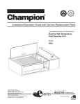
1
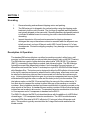
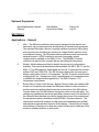
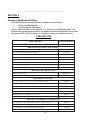
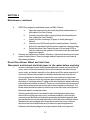
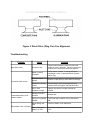
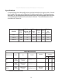
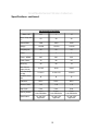
Installation & Service Manual for Small Media Collectors Models SM-5 SM-12 SMH-12 February 27, 2003 Small Media Series Filtration Collectors Table of Contents Disclaimer ....................................................................................................... 3 Uncrating ......................................................................................................... 4 Description & Operation ................................................................................. 4 Optional Equipment ........................................................................................ 5 Applications - General .................................................................................... 5 Installation ....................................................................................................... 6 Installation continued ...................................................................................... 7 Figure 1 Typical Drain Installation ................................................................... 7 Installation continued ...................................................................................... 8 Installation continued ...................................................................................... 9 Figure 2 Wire Connection Diagram ................................................................ 9 Ordering Replacement Parts ........................................................................ 10 Maintenance .................................................................................................. 11 Maintenance continued ................................................................................. 12 Figure 3 Direct Drive Plug Fan Fan Alignment ............................................. 13 Troubleshooting ............................................................................................ 13 Specifications ............................................................................................... 14 Specifications continued .............................................................................. 15 Limited Warranty ........................................................................................... 16 2 Small Media Series Filtration Collectors Disclaimer Although instructions and recommendations are included for installation of your Small Media Collector, the manufacturer does not assume responsibility for the installation of this equipment nor shall he be held liable for direct or consequential damages resulting from improper installation, application, maintenance or use. The immense variety of contaminants make it impossible to list all of the potential hazards that may be encountered with air pollution control systems. It is therefore important that the application of the equipment be discussed with an AER Control Systems representative or application engineer prior to use. Additionally, users should consult and comply with all National and Local Fire, Electrical and /or other appropriate codes when determining the application, location and operation of any air pollution control equipment. Collection of combustible or explosive materials and collection on flame or spark-generating operations may require specific system configurations (contact AER Control Systems LLC. Applications Engineering Department for questions and/or design assistance). The combined collection of combustible or explosive materials and contaminants from spark or flame generating operations, with a common collector or duct system, is not recommended, unless special design provisions have been made to the system (sparks or flames resulting from such operations may ignite the combustible or explosive material). Under no circumstances should anyone be allowed to discard a lighted cigarette, other burning materials, or refuse into an inlet hood or the duct of the collection system. It is the responsibility of the end user to comply with all applicable national, state, and local fire and safety codes. This manual should be read completely before attempting Operation or Maintenance of this equipment. All work should be performed by qualified personnel according to local requirements. All data and dimensions in this manual have been thoroughly checked however, we cannot assume responsibility for possible errors or omissions. We reserve the right to change designs and/or specifications without notice. WARNING Failure to comply fully with the following instructions and local code requirements may increase your risk of physical injury due to fire, explosion or electrical shock. 3 Small Media Series Filtration Collectors SECTION 1 Uncrating 1. Remove banding and cardboard shipping carton and packing. 2. The SM series unit is shipped in the vertical position using the shipping angle brackets to bolt the unit to the skid. The four legs (if supplied) and inlet plenum are typically shipped on the same skid. Mounting hardware and gasket material is included in labeled boxes for mounting, be sure to check all boxes before discarding. 3. Inspect the exterior of the unit and accessories for shipping damage or shortages that may not have been noticed or recorded when the shipment was initially received, you have 30 days to notify AER Control Systems LLC of any discrepencies. Contact the shipping company if any damage or shortages have occurred. Description & Operation The standard SM series collectors can either be machine mounted, ceiling hung, wall mounted, or floor mounted with an optional inlet plenum/leg kit (only on the SM-12 series). The SM collectors consist of either an bottom pan w/collar (SM-5 & SM-12) or plenum (SM-12), a standard 3 stage filtration module, and a blower module. The SM collectors typically house wet filter stages that include a 4 inch cleanable Chevron Impinger, a 1 cleanable metal mesh filter, and a 12 inch deep box style 95% ASHRAE efficient disposable fiberglass filter. The bottom pan is designed to allow the SM collector to be mounted to the top of a machine enclosure or when the unit is ceiling hung, a flex hose or duct can be attached to the bottom inlet and then be connected to a collar on the machine enclosure. Units equipped with the bottom pan, do not require a seperate drain hose as fluids will drain back through the collar, or collar and flex hose (or duct) into the machine. The inlet plenum option on the SM-12 has a drain fitting for removal of the coolant and a 10 foot drain hose to transport the coolant to either the sump of the machine or a suitable container. Also included as standard is a blower module which is typically mounted on the clean air side of the filters. A standard blower module consists of a direct drive backward inclined fan and an electric drive motor. The standard fan/motor combination for the SM-5 is ½ horsepower and a 1 horsepower is standard on the SM-12. The SMH-12 collector the SM12 unit described above with the addition of a HEPA Module and larger, 1 1/2 horsepower fan/motor combination. The HEPA module houses a standard HEPA filter rated at 99.97% efficient at 0.3 microns (other efficiencies available). This module is typically mounted after the 3 stage filter module and before the blower module. 4 Small Media Series Filtration Collectors Optional Equipment Mounting Brackets & stands Silencer Drain Bottles Hose Kits w/Collars Plenum Kit Leg Kit SECTION 2 Applications - General 1. Mist The SM series collectors are primarily designed for the capture and removal of mist contaminants from a wide variety of manufacturing processes. The standard SM series collector is typically machine mounted or ceiling hung with an bottom pan w/collar and consists of a 3 stage filtration cabinet, and a motor/blower housing. The SM series collector can also be wall mounted with optional bracket. A HEPA module for removal of secondary smoke contaminants is available on the SMH-12 Unit. The SM/SMH-12 series collectors can also be floor mounted with an optional leg kit/inlet plenum. 2. Models - Model codes are utilized to identify the various unit configurations available. There are three standard models available, the SM-5, SM-12, and the SMH-12. The SM stands for Small Media and the 5 & 12 represent the nominal airflow of 500 and 1200 CFM. The SM-5 series collector has only one motor/ blower configuration, which is ½ horsepower. The SM-12 has two motor/blower configurations, the 1 horsepower motor is standard and a ½ horsepower motor is available for derated airflow applications. The SMH12 uses a 1-1/2 Horsepower motor/blower. 3. Bottom Pan w/ Collar & Inlet Plenum Bottom Pans w/ collars are standard with a base unit, the bottom pan allows the SM series collector to be mounted to a machine enclosure and provides the air inlet to the bottom of the SM collector. Coolant drains out of the SM collector through the collar on the collar plate. For ceiling hung installations, the bottom pan allows a hose or duct to be attached to the collar and then attached to a collar or hood at the source of the contaminant. An inlet plenum option is available on the SM/SMH-12 series collectors. The inlet plenum comes with a choice of collar sizes (size dependent upon airflow) and requires a seperate drain hose for fluid drainage. A drain fitting is located on the bottom of the plenum to allow the coolant to drain back to the sump of the machine, suitable container, or drain bottle. 5 Small Media Series Filtration Collectors SECTION 3 Installation Assembly & Installation SM Series Collectors 1. Standard collectors are shipped without the bottom pan or inlet plenum and leg kit installed (mounting hardware and gasketing is included). The standard SM series is shipped in the vertical position on the skid using L shaped angled mounting brackets. Installation consists of machine mount or ceiling hung with bottom pan, wall mount with bracket, or floor mount with leg kit (only on SM/SMH-12 series). The same L-shaped angled shipping mounting bracket as mentioned above can be used for lifting and to ceiling mount the unit. 2. Machine Mounting - Machine mounting is easy with the bottom pan, one side attaches to the bottom of the SM series collector using supplied hardware and gasketing. The collar side of the plate is inserted into a hole cut into the top of a machine enclosure. Decide on a location on top of the machine enclosure and use the bottom pan as a template to cut the round hole in the machine enclosure. Insert the collar through the hole of the enclosure and screw down the pan to the enclosure. Sealant can be applied between the top of the enclosure and the bottom pan if sealing is an issue. Apply gasketing (supplied) to inside lip of the bottom pan and lower SM collector into the pan. Fasten collector to pan using hardware (supplied) and insert bolts through the holes in the bottom pan to the bottom four corners (weldnuts) of the collector. 3. Floor Mounting - The leg kit (if supplied) can be bolted to the unit using the hardware shipped with the unit. Once the legs are attached to the SM/SMH-12 unit, it should be located as close to the pick up source as possible. The SM/ SMH-12 unit with legs should be level and bolted to the floor. 4. Ceiling Hung - For suspended installations the L shaped angle bracket can be attached to the top of the 3 stage media module and either threaded rod or cable can be used to suspend the unit from the ceiling. The bottom pan can be attached to the bottom of the SM series Collector (See machine mounting section for bottom pan attachment). A Flex hose or duct is attached to the collar on the bottom pan and the other end is attached to a collar or hood at the source of the contaminant. 5. Wall Mounting - Optional Wall Mount Brackets are available to mount the SM units to a vertical wall or the side of a machine enclosure. Before mounting, ensure that the wall has suffcient strength to support the SM unit. The brackets are attached to the top of the third stage media module, and the assembly is fastened to the vertical wall with suitablemounting hardware (customer supplied). 6 Small Media Series Filtration Collectors SECTION 3 Installation continued 6. Inlet Plenum - The inlet plenum is only available on the SM/SMH-12 series collectors, the plenum is shipped with a drain fitting and 10 feet of 1 1/4 inch drain hose. The drain fitting is typically installed in the bottom of the inlet plenum, the drain hose barb is shipped loose and should be installed in the fitting. The drain hose slips over the barb fitting and the other end should be submerged in the sump of the machine or container. If the end of the drain hose cannot be submerged, then a loop should be created with the hose to provide a trap similar to the trap under a household sink. An alternative is to attach an air tight drain bottle to the bottom of the inlet plenum (two sizes are available as an option from AER Control Systems LLC). This is necessary so air is not drawn up through the drain line which would prevent fluid drainage. The inlet collars should be attached to the outside of the SM/SMH-12 unit using a sealant such as silicone or any other sealant that is suitable with the coolant used. The collars can be added before or after the unit is mounted to the inlet plenum. Figure 1 Typical Drain Installation 7 Small Media Series Filtration Collectors SECTION 3 Installation continued Electrical 1. Single phase 115V 60HZ units are standard prewired from the factory, and include an On/Off switch wired to the electric motor with a power cord for single phase power. Single phase 230V and three phase units are an option, but do not include a switch, cord, or plug. All three phase and 230V single phase units are wired for the input voltage specified on the purchase order. 2. Motors used on the SM series collectors are UL recognized and internal wiring is UL rated at 600 volts. Input power line protection is required for the motor and electrical components. Line load and current requirements are identified on the motor nameplate. Unless ordered with the machine, the power switch for operating the machine, any fusible disconnect, motor starter or controller are to be provided by the customer/user and located externally to the machine. 3. All connections to the non-standard units are made at the motor electrical box (three phase & 230V single phase). Wiring diagrams can be found on the motor nameplate or on the motor electrical box. Verify the incoming voltage and that the motor has been properly wired prior to connecting it to the machine. 4. Verify proper rotation of the blower motor. It will be necessary to view the blower wheel from the blower exhaust on the SM series unit to verify the rotation. Proper rotation is marked on the motor housing. The blower wheel should be rotating clockwise when viewed from the motor end of the wheel. Counterclock wise from the blower inlet cone side of the wheel. If opposite rotation is experienced, see Figure 2 for directions to switch rotation. NOTE A motor starter with overload protection must be provided by the User. Thermal overload heaters are installed in the external motor starter. Consult the starter manufacturer for recommended heater size for the installed motor. WARNING Permanent damage to the motor will be sustained if connected to voltages other than the normal operating voltage for which the unit is pre-wired. 8 Small Media Series Filtration Collectors SECTION 3 Installation continued Low Voltage High Voltage Low Voltage 6 5 4 6 5 4 8 5 9 8 7 9 8 7 3 4 3 2 1 3 2 1 1 2 Line Line High Voltage* 2 8 5 1 Line 4 Line * to change rotation flip 5 & 8 Interchange any two line wires to reverse rotation 3 Phase 3 Single Phase Figure 2 Wire Connection Diagram Minihelic Gauge 1. The Minihelic gauge is typically mounted on the 3 stage media module and measures the pressure drop across the 3 stages of filters. If a HEPA module is supplied the same gauge measures the pressure drop across the 3 stages of filters and the HEPA filter. 2. The Minihelic gauge has a red needle that indicates the pressure drop reading. To zero in the gauge, run the collector with clean filters and turn the screw at the bottom face of the gauge to zero. This is your starting point with clean filters in place. Periodically check the design airflow whether it be weekly or monthly to determine if the filters are dirty. Eventually the pressure drop reading will reach a point where there is insufficient airflow to capture the contaminants generated. Mark the gauge face with a black marker at the reading on the Minihelic gauge. In the future a quick look at the gauge will give you a sense of when the filters will need to be changed. In some cases the first or second stage filter could be dirty and the third stage filter (box filter) is fine. To check this scenario, pull out the first or second stage filter to see if the design airflow improves. If it does then either clean or replace the first or second stage and leave the third filter (box filter) alone. At some point the third stage filter (box filter) will need to be changed when removal of the first and second stage filters have little or no change on airflow or on the Minhelic gauge reading. 9 Small Media Series Filtration Collectors SECTION 4 Ordering Replacement Parts Information required for prompt delivery of replacement parts will be: 1. Model and Serial Number 2. Part Number and Description Contact your local AER Control Systems LLC. distributor for replacement parts. Use either our toll free telephone number or our website www.aercontrolsystem.com to obtain the nearest AER Control Systems LLC. distributors name and telephone number. 1-866-265-2372 D escription Part N umber Mi ni heli c Pressure Gauge 1217-01 Miscellaneous H oses and C lamps 4" x 10' Neoprene/Polyester Flexhose 1051-01 6" x 10' Neoprene/Polyester Flexhose 1051-02 8" x 10' Neoprene/Polyester Flexhose 1051-06 10" x 10' Neoprene/Polyester Flexhose 1051-07 Hose C lamp 4" Bri dge 1050-10 Hose C lamp 6" Bri dge 1050-11 Hose C lamp 8' Bri dge 1050-12 Hose C lamp 10" 1050-07 Miscellaneous Spare Parts SM-5 Impi nger C ell SM50018-10 SM-12 Impi nger C ell H10015-01 Miscellaneous Filters XE Box Style Filter 12" x 20" x 12", 95% ASHRAE,23sq.ft. 1036-03 XE Box Style Filter 24" x 24" x 12", 95% ASHRAE, 58sq.ft. 1036-04 Alumi num Prefi lter 1" x12" x 20" 1034-21 6-Pack Alumi num Prefi lters 1" x12" x20" 1034-22 Alumi num Prefi lter 1" x24" x 24" 1034-03 6-Pack Alumi num Prefi lters 1" x24" x 24" 1034-04 HEPA Fi lter 22" x 22" x 12", 99.97% @ .3 mi crons 1040-16 Miscellaneous Motors and Electrical 0.5 HP Motor, 1 PH, 3450 RPM for SM-5 & SM-12 Uni ts 1002-01 1 HP Motor, 1 PH, 3450 RPM for SM-12 Uni ts 1002-03 1.5 HP Motor, 1 PH, 3450 RPMfor SM-12 Uni ts 1002-06 On/Off Swi tch 1206-01 10 Small Media Series Filtration Collectors SECTION 5 Maintenance Operation & Maintenance Lubrication or other routine periodic preventive maintenance is not required. All that is needed is an occasional check of fasteners and a general visual check of the unit to make sure that nothing has gone wrong. Periodic replacement of the filters is required when necessary. Dispose of filters in accordance with local standards and procedures for the material collected. Filter Replacement for the SM Series Collectors Disconnect and lockout electrical power to the motor before servicing Access to all the filters is accomplished by opening the outside removable door on the three stage media module by turning the wing knobs enough to lift the door off the threaded studs. 1. Impinger Replacement on SM collectors: The 4 inch impinger is the first stage of the three stage media module. Once the outside filter access door is opened, the impinger can be removed by sliding the impinger out. The aluminum impinger is cleanable and can be washed with mild detergent or solvent. 2. Aluminum mesh filter replacement on SM collectors: The 1 inch aluminum mesh filter is the second stage of the three stage media module. This filter will be accessible once the lift off door is removed and mesh filter can be slid out of the cabinet. The cleanable aluminum mesh filter can be washed with mild detergent or solvent, but it is important to be gentle while washing. Observe the direction of flow indication on the new replacement filter. Insert the filter with this arrow facing the blower module direction. 3. Box Style Filter Replacement on SM collectors: The box style filter is the third stage of the three stage media module. This filter can be accessed once the lift off door is removed, the box filter can be slid out of the cabinet. Place filter in a plastic bag or dispose of in accordance to local requirements. Observe the direction of flow indication on the filter. Insert the filter with this arrow facing the blower direction. 11 Small Media Series Filtration Collectors SECTION 5 Maintenance continued 4. HEPA Filter Inspection and Replacement on SMH Collector a. 5. Open the access doors, and rotate the yellow handles down on both sides of the Cam Clamps. b. Carefully remove the filter by prying it away from the sealing sur face (toward the Cam Clamps). c. Inspect the filter for damage. If ripped, or visibly damaged, discard. d. Unpack a new HEPA and inspect the sealing surface. Carefully slide it into the cabinet with the gasket toward the metal seal edge e. Rotate the yellow Cam Clamps up and to lift and seal HEPA in cabinet; make sure the gasket is in full contact with the metal seal edge of the cabinet. Cleaning and Inspection of Cabinet: After dirty components have been removed, inspect cabinet interior. Remove foreign material, wipe interior, and clean all filter-seating surfaces. Direct Drive Blower Wheel and Inlet Cone Disconnect and lockout electrical power to the motor before servicing 1. Access to replace the motor and/or blower wheel will require removal of the top cover, motor, and blower assembly. Remove the fasteners that attach the top cover, motor, and blower assembly to the cabinet and lift the entire assembly off of the unit. Reverse this procedure to install the assembly back onto the unit. It is very important to maintain the correct inlet cone insertion into the blower wheel inlet. There can not be any large air gaps between the top of the cone and the bottom of the blower wheel. If a gap occurs then the blower wheels efficiency is diminished and airflow is reduced. There is a curved radius at the blower inlet where the air enters the wheel and the inlet cone is inserted into the wheel. The blower wheel should be located so that the top of the inlet cone is at midpoint of the blower wheels curved inlet radius. Checking and adjustment of the wheel to inlet cone alignment can be done without removing the top cover, motor, and blower assembly. Open the filter access door on the filter module directly preceeding the blower assembly and remove the filters for access and adjustment to the inlet cone and blower wheel. Standard units are equipped with composite fans and inlet cones, however aluminum inlet cones and wheels may be utilized in special applications. Reference the following diagram for proper wheel to inlet cone alignment. 12 Small Media Series Filtration Collectors Figure 3 Direct Drive (Plug Fan) Fan Alignment Troubleshooting Problem Motor fails to start Low airflow and/or suction Contaminant blowing out of collector exhaust Motor/blower noise or vibration Cause Solution No power to unit Check overload heaters in starter and fuses and replace or reset if necessary. Check for proper wire connections to and from the starter and collector. Blower is running backwards Check rotation of blower. If running backwards, interchange 2 of the 3 input power leads (3 phase motors only) Filters are dirty or blocked Replace or clean filters or check filters for blockage Obstruction in ducting or hose Check ducting or hose for blockage.Check for dampers in the duct system, they may be closed. Duct or hose resistance too high Improper duct design or higher pressure fan required. Damaged or hole in the filters Replace filter Filters are not properly installed Check seal edge on HEPA. Check seals around filter Wheel rubbing inlet cone Check for wheel to cone interference. Motor cooling fan is rubbing on cover Adjust motor cooling fan cover so that it does not rub or hit. 13 Small Media Series Filtration Collectors Specifications The specification chart below will give the important information for each module. Overall sizes, weight, filter area can be figured out by totaling module data. The dimensions are taken as if you are facing the access doors on the unit, the doors would be the front of the unit and the depth dimension is from the front to the back. The width dimension is from one side to the other side. M ode l # AER Control Nominal Sys te ms Box CFM Filte r Type Filte r Are a (ft2) M otor (hp) Fan Size Wt.(lbs )w/o ple num SM- 5 500 XE 23 0 .5 8" 95 SM- 12 120 0 XE 58 1 10" 165 SMH- 12 120 0 XE 58 1 .5 11" 283 SM Series Module Specification SM Series Module Prefilter Inter Final/Main Dimensions After filter Depth Height Width SM- 5 Impinger 12x20x4 Aluminum Mesh 1x12x20 Box Filter 23 sq. ft. 21 39* 19 SM- 12 Impinger 24x24x4 Aluminum Mesh 1x12x20 Box Filter 58 sq. ft. 29 42* 26 SMH- 12 Impinger 24x24x4 Aluminum Mesh 1x12x20 Box Filter 58 sq. ft. 29 60* 26 * includes bottom inlet collar 14 HEPA Filter 22x22x12 Small Media Series Filtration Collectors Specifications continued MOTOR SPECIFICATIONS Motor - HP 0.5 1 1.5 Motor Temp. Max -C 40 40 40 3450 3450 3450 115/230 115/230 115/230 60 60 60 1 1 1 56C 56C 56C Power Factor 72 82 85 Efficiency 66 68 70 Start Current Amps (60 Hz.) 21/10.5 38/19 50/25 Full Load Amps (60 Hz) 7/3.6-3.5 11.8/6.1-5.9 16/8.4-8 Insulation Class Min. B B B TEFC TEFC TEFC Service Factor 1.25 1.25 1.15 Duty Cycle Cont. Cont. Cont. Exxon POLYREX®EM Exxon POLYREX®EM Exxon POLYREX®EM UL and CSA Approved UL and CSA Approved UL and CSA Approved Speed RPM Voltage Frequency Hz Phase Frame - NEMA Enclosure Bearing Grease Specification 15 Limited Warranty AER Control Systems LLC warrants all products sold only to purchasers for use in business or for resale, against defects in workmanship or materials under normal use, for one (1) year after the date of purchase from AER Control Systems LLC. Misapplication of the product, decomposition by reaction or chemical action and wear caused by abrasion will not constitute, or be considered as a defect. Warranty is void if the product has been subject to damage, unreasonable use, neglect, improper service, improper installation, or other causes not arising from defects in original materials or workmanship. Any part that is determined to be defective in material or workmanship and returned to an AER Control Systems LLC distributor or authorized service facility, as AER Control Systems LLC designates, shipping costs prepaid, will be, as the exclusive remedy, repaired or replaced at AER Control Systems LLCs option. AER Control Systems LLC shall not be liable for any incidental or consequential cost, expenses, or damages resulting from any failure, defect, or malfunction of this product, liability is expressly disclaimed. AER Control Systems LLCs liability in all events is limited to and will not exceed, the purchase price of the product. Title and risk of loss pass to the buyer on delivery to the common carrier. If a product is damaged in transit, the recipient MUST make note of the damage upon receipt of the product and file a claim with the carrier. AER Control Systems LLC will make a good faith effort for prompt correction or other adjustment, with respect to any product that proves to be defective within the warranty period. Collection of combustible or explosive materials and collection on flame or spark-generating operation any require specific system configurations (contact AER Control Systems LLCs Applications Engineering Department for questions and/or design assistance). The combined collection of combustible or explosive materials and contaminants from spark or flame generating operations, with a common collector or duct system, is not recommended, unless special design provisions have been made to the system (sparks or flames resulting from such operations may ignite the combustible or explosive material). Under no circumstances should anyone be allowed to discard a lighted cigarette, other burning materials, or refuse into an inlet hood or the duct of the collection system. It is the responsibility of the end user to comply with all applicable national, state, and local fire and safety codes. AER Control Systems LLCs liabiltiy for consequential and incidental damage resulting from a fire or explosion is expressly disclaimed. Installation of suitable overload protection such as a motor starter, according to NEC guidelines, is required. Failure to provide proper overload protection will void warranty coverage on electrical components in the system. (Combination motor starters with fusible disconnect packages are available through your local AER Control Systems LLC representative). To ensure optimum collector performance, always use AER Control Systems LLC replacement filters.