1
MITSUBISHI ELECTRIC
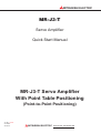
MR-J3-T
Servo Amplifier
Quick Start Manual
MR-J3-T Servo Amplifier
With Point Table Positioning
(Point-to-Point Positioning)
Art. No.: xxxxxx
21122007
Version A
MITSUBISHI ELECTRIC
INDUSTRIAL AUTOMATION
About This Manual
If you have any questions about programming or operating the equipment
described in this manual please don’t hesitate to contact your dealer or
one of our official distributors (see back cover).
You can find up-to-date information and answers to frequently-asked
questions on our website (www.mitsubishi-automation.com).
MITSUBISHI ELECTRIC EUROPE B.V. reserves the right to make
technical changes to the products or this manual at any time without prior
notice.
© December 2007
MITSUBISHI ELECTRIC EUROPE B.V.
Quick Start Manual
MR-J3-T Servo Amplifier with Integrated Point Table Positioning
Art. No.: xxxxxx
Version
A
10/2007
Changes / Additions / Corrections
pdp
First Edition
This Quick Start Manual for the servo amplifiers of the MR-J3-T series with point table positioning is designed to enable you to get your system installed and configured for use as quickly as
possible. Please note that this guide only covers the basic functions with the instructions necessary to use these functions. Complete descriptions of all the supported functions and all available extensions can be found in the instruction manuals.
Please also note that the servo amplifiers of the MR-J3-T series include the following additional
major functions that are not covered in this Quick Start Manual:
쎲 Communication via a serial port for controlling point table positioning
쎲 Positioning control in BCD format with the optional MR-DS60 digital switch
쎲 Amplifier controller circuit settings and auto-tuning functions
Safety Instructions
To ensure safe and proper installation of the equipment please also observe the instructions and
safety precautions in the instruction manuals supplied for your hardware.
Notes in this Quick Start Manual:
NOTE
Tips and useful information.
Additional documentation:
쎲 MR-J3-T Instruction Manual (SH(NA030061-A)
쎲 MR-J3-T Instruction Manual for CC-Link (SH(NA030058-B)
쎲 Instruction Manual for the CC-Link Master Module:
– QJ61BT11N
– A1SJ61BT11
– A1SJ61QBT11
– FX2N-16CCL-M
MR-J3-T
i
Contents
1
Introduction
1.1
Preparations . . . . . . . . . . . . . . . . . . . . . . . . . . . . . . . . . . . . . . . . . . . . . . . . . . . . .1-1
2
Installing the Equipment
2.1
Installing the MR-J3-D01 Extension . . . . . . . . . . . . . . . . . . . . . . . . . . . . . . . . . . .2-3
3
First Functional Test
3.1
Minimum Connections for the Functional Check . . . . . . . . . . . . . . . . . . . . . . . . . . . . . 3-5
3.1.1
3.2
Functional Test Settings. . . . . . . . . . . . . . . . . . . . . . . . . . . . . . . . . . . . . . . . . . . . .3-7
3.3
Configuring Positioning Point Tables . . . . . . . . . . . . . . . . . . . . . . . . . . . . . . . . . . .3-9
3.4
Functional Test with MR Configurator . . . . . . . . . . . . . . . . . . . . . . . . . . . . . . . . . 3-10
3.4.1
Selecting point table position entries . . . . . . . . . . . . . . . . . . . . . . . . . . 3-10
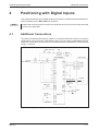
4
Positioning with Digital Inputs
4.1
Additional Connections . . . . . . . . . . . . . . . . . . . . . . . . . . . . . . . . . . . . . . . . . . . .4-11
4.2
Turning off Automatic Input Signal Activation . . . . . . . . . . . . . . . . . . . . . . . . . . . 4-14
4.3
Home Position Return. . . . . . . . . . . . . . . . . . . . . . . . . . . . . . . . . . . . . . . . . . . . .4-15
4.4
4.3.1
Dogless Z-phase reference mode. . . . . . . . . . . . . . . . . . . . . . . . . . . . . 4-15
4.3.2
Dog mode home position return . . . . . . . . . . . . . . . . . . . . . . . . . . . . . . 4-19
Configuration for Positioning . . . . . . . . . . . . . . . . . . . . . . . . . . . . . . . . . . . . . . . .4-23
4.4.1
ii
Connector pin assignments. . . . . . . . . . . . . . . . . . . . . . . . . . . . . . . . . . .3-6
Importing and exporting point tables. . . . . . . . . . . . . . . . . . . . . . . . . . . 4-26
4.5
Functional Test of Digital Input Positioning . . . . . . . . . . . . . . . . . . . . . . . . . . . . . . 4-28
5
Positioning via a CC-Link Network
5.1
Additional Connections . . . . . . . . . . . . . . . . . . . . . . . . . . . . . . . . . . . . . . . . . . . .5-31
5.2
CC-Link Communication Settings . . . . . . . . . . . . . . . . . . . . . . . . . . . . . . . . . . . .5-33
5.2.1
Settings on the servo amplifier . . . . . . . . . . . . . . . . . . . . . . . . . . . . . . . 5-33
5.2.2
Configuration for communication with GX IEC Developer . . . . . . . . . . 5-35
5.3
Testing the Servo Amplifier via CC-Link . . . . . . . . . . . . . . . . . . . . . . . . . . . . . . . 5-37
A
Appendix
A.1
Digital Signals − Quick Reference. . . . . . . . . . . . . . . . . . . . . . . . . . . . . . . . . . . .A-39
A.2
Standard Parameters − Quick Reference . . . . . . . . . . . . . . . . . . . . . . . . . . . . . . A-40
A.3
Alarms and Warning Messages . . . . . . . . . . . . . . . . . . . . . . . . . . . . . . . . . . . . . . .A-41
MITSUBISHI ELECTRIC
Introduction
1
Preparations
Introduction
The servo amplifiers of the MR-J3-T series are designed specifically for drive positioning applications using point-to-point positioning without interpolation or trajectory control. The positions
to be accessed stored in a table and can be selected cyclically, individually or in any order with:
쎲 Digital signals
쎲 CC-Link communication
The MR Configurator setup software package enables the user to test the entered positioning
steps quickly and easily in test mode.
1.1
Preparations
The following products and parts are needed for using the point table positioning features described in this manual:
쎲 A servo amplifier, for example MR-J3-10T
쎲 A servo motor compatible with the selected amplifier
Example: HF-KP13 motor for the MR-J3-10T servo amplifier
쎲 MRZJW3-SETUP221E Version C0 of the MR Configurator setup software package
쎲 MR-J3USBCBL3M USB cable for connecting your PC/notebook with the servo amplifier
쎲 MR-PWS1CBL M-A1-L motor connection cable
쎲 MR-J3ENCBL M-A2-L rotary encoder cable
쎲 MR-J2CMP2 connector for CN6 I/O signal connector
쎲 Power supply cables conforming to the applicable installation regulations
쎲 Connection cables for the control terminals
Required for positioning control with digital signals:
쎲 MR-J3CN1 connector for communication connector CN10
쎲 Optional MR-J3-D01 expansion card
Useful but not absolutely necessary:
쎲 Simulation Box and terminal block with connection cable for testing:
FX Simulation Box (Art. No. 3386)
MR-TB50 terminal block for CN10 (MR-J3-D01)
MR-J2M-CN1TBL•M cable for connecting CN10 to MR-TB50
MR-J3-T
1-1
Preparations
Introduction
Required for positioning control via a CC-Link network:
쎲 Q-Rack with PLC and the CC-Link module QJ61BT11N
or
A–Rack with PLC and CC-Link module A1SJ61BT11, A1SJ61QBT11 or FX2N-16CCL-M
쎲 CC-Link cable compatible with version V1.10 Standard
쎲 Cable for connecting the PC/notebook to the PLC CPU:
Q series: SC-Q QC30R2
A and FX series: SC-09
쎲 The GX IEC Developer programming software package for configuration of the data communications settings
NOTE
1-2
This Quick Start Manual describes the installation and setup of a typical servo system consisting of an MR-J3-10T servo amplifier (single-phase, 230V / 100W) and an HF-KP13 servo motor. Note that the specifications of this sample system may differ from those of your
configuration – please check your equipment’s instruction manuals for details if necessary.
MITSUBISHI ELECTRIC
Installing the Equipment
2
Installing the MR-J3-D01 Extension
Installing the Equipment
The procedure for the physical installation of the MR-J3-T series hardware is exactly the same
as for the MR-J3-A and MR-J3-B models. The dimensions of the MR-J3-T series amplifiers are
identical to those of the matching models of the MR-J3-A and MR-J3-B series.
NOTE
2.1
Please consult the instruction manual for detailed installation instructions.
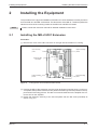
Installing the MR-J3-D01 Extension
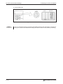
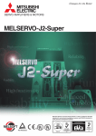
Procedure:
햲 Remove the cover of the CN7 connector on the right side of the MR-J3-T housing.
Upper mounting
point 2
Upper mounting
point 1
Cover for CN7
connector
Lower mounting
point 2
Fig. 2-1:
Lower mounting
point 1
Fixing points of the extension MR-J3-D01
햳 Position the MR-J3-D01 extension over the upper and lower mounting points 1 on the servo amplifier, then press the extension into place so that the lugs click into position in the upper and lower mounting points 2. This also connects the extension to the amplifier via connector CN7 on the amplifier.
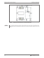
햴 Fasten the extension securely to the servo amplifier with the M4 screw (included) as
shown in Fig. 2-2.
MR-J3-T
2-3
Installing the MR-J3-D01 Extension
Fig. 2-2:
NOTE
2-4
Installing the Equipment
Fastening screw dimensions for extension MR-J3-D01
To uninstall the extension perform the above steps in the reverse order. To release the retaining clips press the retaining tabs marked “Push” inwards and pull the extension out to the
side.
MITSUBISHI ELECTRIC
First Functional Test
3
Minimum Connections for the Functional Check
First Functional Test
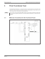
The wiring diagram below (Fig. 3-1) shows the minimum connections that you must make to test
an MR-J3-T series amplifier with the MR Configurator setup software. In test mode you can
check whether all the components are working properly.
NOTE
3.1
You can also use the optional MR-PRU-03 HMI control terminal for performing initial tests
and setting the amplifier’s parameters. For further details see the MR-J3-T series instruction
manual.
Minimum Connections for the Functional Check
Servo motor
1-phase
200–230V AC
Fig. 3-1:
MR-J3-T
Motor
Wiring diagram for minimum configuration without control terminals
3-5
Minimum Connections for the Functional Check
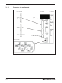
3.1.1
First Functional Test
Connector pin assignments
Servo amplifier
MR-J3-첸T
Power terminals
I/O extension
MR-J3-D01
USB
port
Connector CN2
Fig. 3-2:
3-6
Power and control connector pin assignments for minimum configuration
MITSUBISHI ELECTRIC
First Functional Test
3.2
Functional Test Settings
Functional Test Settings
The following input signals are required to activate the servo amplifier’s motor output:
쎲 EMG -> Force stop (safety signal)
쎲 SON -> Servo ON
쎲 LSP -> Forward rotation stroke end (limit switch)
쎲 LSN -> Reverse rotation stroke end (limit switch)
You can configure the servo amplifier to activate these signals automatically when the power is
switched on:
Procedure:
햲 Connect the PC / notebook to the servo amplifier’s USB port (CN5) with the
MR-J3USBCBL3M cable.
햳 Start MR Configurator on the computer and make the following settings:
– Select the MR-J3-T series servo amplifier:
�
�
�
Fig. 3-3:
MR-J3-T
Selecting the servo amplifier
3-7
Functional Test Settings
First Functional Test
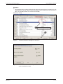
– Set the parameter for the automatic activation of the EMG, SON and LSP/LSN input
signals:
Parameter PD01 “Input signal automatic ON selection 1” = 1C04
�
�
�
Fig. 3-4:
Parameter settings for automatic input signal activation.
– Turn the servo amplifier off and then turn it on again to initialise the new parameter setting.
3-8
MITSUBISHI ELECTRIC
First Functional Test
3.3
Configuring Positioning Point Tables
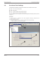
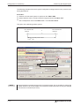
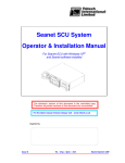
Configuring Positioning Point Tables
The position values, travel speeds and acceleration and deceleration times are stored in tables
known as “point tables”. We will now go through the steps required to configure and define a
point table.
Procedure:
햲 Select the Point Table option from the Point-data menu.
햳 Enter the values for the movements (position, speed, acceleration and deceleration times)
in the Point Table List window, using one line for each movement:
– Enter target position (a) in µm x 10STM (STM: e in diagram).
– Enter speed (b) in rpm.
– Enter acceleration/deceleration times (c) and (d) in ms as required for the motor’s rated
speed.
햴 Save the entries by clicking on the Write All button.
a
�
b
c
d
{
e
Fig. 3-5:
�
�
Point table positioning entries in the point table list window
Make sure that the Aux. Func. value in every line is left at the default factory setting (“0”) to
ensure that selecting a position value in the table does not inadvertently activate any subsequent table entries.
NOTES
In the factory default settings the absolute value command system for the target positions is
activated with parameter PA01 “*STY”. When this system is active all target position values
are referred to the physical home position. Alternatively you can also select the incremental
value command system. The absolute position detection system for the home return function can be set with parameter PA03 “*ABS” (see chapter 4.3).
Loading the factory defaults will not overwrite your point table entries.
MR-J3-T
3-9
Functional Test with MR Configurator
3.4
First Functional Test
Functional Test with MR Configurator
Using MR Configurator you can perform a basic test of the individual positioning steps and make
adjustments for your application. Note that setting parameter PA14 does not have any effect on
the rotation direction in jog mode when using MR Configurator. The rotation directions are
defined as follows, looking at the end of the drive shaft (i.e. towards the motor):
쎲 FORWARD -> anticlockwise
쎲 REVERSE -> clockwise
NOTES
Home position return is not possible in test mode when using MR Configurator – use the jog
function to move to the starting position.
You can set the rotation direction in “single-step feed mode” with parameter PA14.
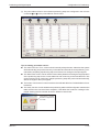
3.4.1
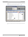
Selecting point table position entries
Procedure:
햲 Select Single-step Feed � in the Test menu.
햳 To select a position enter its point table line number in the dialog box displayed �.
햴 Start the positioning operation �.
�
�
�
Fig. 3-6:
3 - 10
Single-step Feed window for testing individual positioning steps
MITSUBISHI ELECTRIC
Positioning with Digital Inputs
4
Additional Connections
Positioning with Digital Inputs
This chapter describes how point table positioning is used in most applications with the MR-J3-T
series amplifiers and the MR-J3-D01 I/O extension.
NOTE
4.1
Please refer to the instruction manual if you need other functions other than those described
here for your application.
Additional Connections
The initial functional tests described in chapter 3.1 were performed with a minimum connection
configuration. For the full range of standard functions you now need to make additional power
supply and control terminal connections on the CN6 and CN10 terminal blocks, as shown below
in Figs. 4-1 and 4-2.
EMG. OFF OFF
ON
Servo amplifier
Servo motor
1-phase
200–230V AC
Motor
Encoder cable
Encoder
24V DC
EMG. OFF
24V DC ±10%
150mA
Alarm
24V DC
24V DC ± 10 %
800 mA
Servo ON
Fig. 4-1:
MR-J3-T
Single-phase power connections for the MR-J3-T amplifier
4 - 11
Additional Connections
Positioning with Digital Inputs
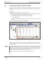
Connector CN6
Fig. 4-2:
4 - 12
Connector CN10
CN10 pin assignments
1
DI0
2
DI1
3
DI2
4
DI3
5
DI4
6
DI5
7
DI6
8
DI7
13
DICOM
14
DICOM
21
SON
22
ACD0
23
ACD1
24
ACD2
25
ACD3
26
RES
32
MD0
35
ST1
36
ST2
37
DOCOM
49
INP
Pin assignments of connectors CN6 and CN10
MITSUBISHI ELECTRIC
Positioning with Digital Inputs
Additional Connections
24V DC ±10%
150mA 햲
24V DC
EMG. OFF
Proximity dog
Forward stroke end
Reverse stroke end
max. 10m
max. 10m
MR-J3USBCBL3M
(Option)
24V DC ±10%
800mA 햲
24V DC
Alarm code
Point
table
selection
SERVO ON
RESET
Automatic/Manuall
Forward rotation start
Reverse rotation start
max.10 m
In position
max. 10m
햲
A 24V 1000mA power supply can be
used for all control terminals.
Fig. 4-3:
NOTES
Connection of the control terminals with PNP logic (source logic)
You can find a brief descriptions of the signal functions in Appendix A.1. Please refer to the
instruction manual for a complete reference.
All digital signals described in this manual use source logic.
For safety reasons the EMG signal must be connected to pin 1 of connector CN6 if the
servo amplifier is not operated during the first functional test. The EMG signal is permanently assigned to pin 1 and the amplifier is deactivated when there is no EMG signal if it is
configured accordingly (see chapter 3.2).
MR-J3-T
4 - 13
Turning off Automatic Input Signal Activation
4.2
Positioning with Digital Inputs
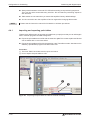
Turning off Automatic Input Signal Activation
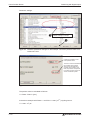
Procedure:
햲 Reset parameter PD01 to a value of "0":
�
Fig. 4-4:
4 - 14
Switching off automatic input signal activation
MITSUBISHI ELECTRIC
Positioning with Digital Inputs
4.3
Home Position Return
Home Position Return
At the factory the MR-J3-T servo amplifiers are configured with the incremental system activated by default (i.e. the absolute position detection system is switched off). This means that the
current position is not stored when the amplifier's power supply is switched off, making it necessary to perform a return to home position every time the unit is powered up. You can configure
the home position return mode with Parameter PC02:
Parameter PC02
Home position return modes
0: Proximity dog mode
1: Count mode
2: Data setting mode
3: Stopper mode
4: Ignore home position
5: Dog mode, rear end reference
6: Count mode, front end reference
7: Dog cradle mode
8: Dog mode, last Z-phase reference
9: Dog mode, front end reference
A: Dogless Z-phase reference
The most commonly used modes are:
1. Dogless Z-phase reference mode (A)
2. Proximity dog mode (0)
These two modes are described in detail below. Dogless Z-phase reference mode is suitable for
simple applications. Dog mode is frequently used for standard applications.
4.3.1
Dogless Z-phase reference mode
In this mode the Z-phase of the rotary encoder (zero position of the encoder) is used as the
machine's physical home position. However, it is quite rare to be able to configure a machine so
that its physical home position exactly matches the Z-phase of the encoder. It is thus almost
always necessary to enter an offset (shift) with parameter PC06.
After activation of the forward start command ST1 (or reverse ST2) the home position return is
initiated by parameter PC04 (“home position return speed”). When the Z-phase signal from the
encoder is registered the servo motor brakes to a halt. After this a precise return to home is performed at creep speed with parameter PC05.
The physical home position can be shifted in relation to the zero position of the encoder
(Z-phase) with the home position offset (shift) defined with parameter PC06. Parameter PC07
can be used to define a home position value other than zero.
When the home position return has been completed successfully the servo amplifier activates
the ZP signal.
MR-J3-T
4 - 15
Home Position Return
Positioning with Digital Inputs
Timing chart:
Auto/Manual mode (MD0)
ON
OFF
Select point table no. (DI0)
Start command
Forward (ST1)
ON
OFF
Start command
Reverse (ST2)
ON
OFF
PC04 “Home pos. return speed”
Servo motor speed setting
PC06 “Home offset”
PC05 “Creep speed”
Z-phase of encoder
ON
OFF
Home return complete (ZP)
ON
OFF
Fig. 4-5:
Home position return sequence in dogless Z-phase reference mode
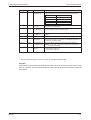
No.
Code
Function
Description
PA05 햲
*FTY
Feed length multiplication factor
Needed here to scale the home position value to the physical coordinate system.
PC02 햲
*ZTY
Home position return mode
Selects the home position return mode:
A: Dogless Z-phase reference mode
PC03 햲
*ZDIR
Home position return direction
0: Incrementing counting of encoder pulses
1: Decrementing counting of encoder pulses
PC04
ZRF
Home position return speed
Sets home position return speed until first detection of the Z-phase
in [rpm].
PC05
CRF
Creep speed
Speed for precise movement to home position in [rpm].
PC06
ZST
Home position off- Distance between the encoder zero point (Z-phase) and the physiset (shift)
cal home position in [µm].
PC07 햲
*ZPS
Home position re- The home position return stops when the Z-phase position is
turn position value reached.You can enter a non-zero coordinate for this position [in
10STMµm] with this parameter.
Table 4-1: Parameter reference table
햲
4 - 16
You must turn the power off and on again to activate this parameter.
MITSUBISHI ELECTRIC
Positioning with Digital Inputs
Home Position Return
Examples:
햲 The Z-phase of the encoder is defined as the physical home position of the machine. In this
example we are going to perform the home position return at 200 rpm in the direction in
which the encoder pulses are counted incrementally.
Parameter settings:
� Parameter settings for example
�
MR-J3-T
Fig. 4-6:
Relevant parameter settings for example 1
Fig. 4-7:
Values shown when the home position return has
been completed correctly
4 - 17
Home Position Return
Positioning with Digital Inputs
햳 Perform a home position return as in example 1 but with an offset between the physical and
encoder home positions, set with parameter PC06.
Parameter settings:
� Parameter settings for example
�
Fig. 4-8:
Relevant parameter settings for example 2. The offset is entered with parameter PC06.
Following completion of the home
position return:
The servo motor has travelled to
the specified home position. The
home position of the encoder has
been exceeded by the value of
PC06 = 3,000 µm. For the motor
connected this is equivalent to
259,144 encoder pulses.
Fig. 4-9:
4 - 18
Values shown when the home position return has been completed correctly
MITSUBISHI ELECTRIC
Positioning with Digital Inputs
4.3.2
Home Position Return
Dog mode home position return
In this mode, instead of the encoder Z-phase(Fig. 4-6), the DOG signal is used to switch from
“home position return speed” PC04 to “creep speed” PC05. You can use parameter PD16 “proximity dog detection polarity” to specify whether a logical “1” or a logical “0” should be identified as
an active DOG signal.
As in 햲 above, the physical home position can be shifted in relation to the home (zero) position
of the encoder (Z-phase) with PC06 “home position offset (shift)”. In addition to this you can also
set a non-zero coordinate for the home position with PC07.
Conditions for the proximity dog signal:
The proximity dog signal (DOG) must fulfill the following conditions to ensure that the Z-phase of
the encoder is detected during the activation period of the DOG signal:
L1 암
V td
폷
60 2
L2 암 2 폷 욼S
MR-J3-T
L1 = Length of the DOG signal in [mm]
V = Home position return speed in [mm/min]
td = Deceleration time in [s]
L2 = Length of the DOG signal in [mm]
욼S = Distance for one rotation of the motor in [mm]
4 - 19
Home Position Return
Positioning with Digital Inputs
Timing chart:
Auto/Manual mode (MD0)
ON
OFF
Select point table no. (DI0)
Start command
Forward (ST1)
ON
OFF
Start command
Reverse (ST2)
ON
OFF
PC04 “Home pos. return speed”
PC05 “Creep speed”
Servo motor speed setting
PC06 “Home offset”
Z-phase of encoder
ON
OFF
DOG signal
ON
OFF
Home return complete (ZP)
ON
OFF
Fig. 4-10: Home position return in proximity dog mode
4 - 20
MITSUBISHI ELECTRIC
Positioning with Digital Inputs
Home Position Return
No.
Code
Function
Description
PA05 햲
*FTY
Feed length multiplication factor
Needed here to scale the home position value to the physical coordinate system when a home position offset (shift) has been set.
Parameter value
Multiplication factor STM
0
1
1
10
2
100
3
1000
PC02 햲
*ZTY
Home position return mode
Selects the home position return mode:
0: Proximity dog mode (DOG)
PC03 햲
*ZDIR
Home position return direction
0: Incrementing counting of encoder pulses
1: Decrementing counting of encoder pulses
PC04
ZRF
Home position return speed
Sets home position return speed until first detection of the Z-phase
in [rpm].
PC05
CRF
Creep speed
Speed for precise movement to home position in [rpm]
PC06
ZST
Home position
offset (shift)
Distance between the encoder home position (Z-phase) and the
physical home position in [µm]. Does not change the zero point of
the physical coordinate system.
PC07 햲
*ZPS
Home position re- The home position return stops when the Z-phase position is
turn position value reached.You can enter a non-zero coordinate for this position [in
10STMµm] with this parameter.
PD16 햲
*DIAB
Input signal
polarity
Logical value for detection of the proximity dog signal (DOG):
0: Active DOG on logical "0"
1: Active DOG on logical "1"
Table 4-2: Parameter reference table
햲
You must turn the power off and on again to activate this parameter.
Example:
In the following example the physical home position is at the position of the Z-phase of the
encoder. However, we now want to assign a non-zero value in the physical coordinate system to
this position.
MR-J3-T
4 - 21
Home Position Return
Positioning with Digital Inputs
Parameter settings:
� Parameter settings for example
�
Fig. 4-11: Relevant parameter settings for the example. The home position value is entered with PC07.
Following completion of the
home position return:
The servo motor has travelled to
the encoder home position
which is also the machine’s
physical home position. However, this position corresponds
to a value of 100mm in the machine’s coordinate system.
Fig. 4-12: Values shown when the home position return has been completed correctly
The position value is calculated as follows:
X = PA05 폷 PC07 in [mm]
In the above example with PA05 = 1 and PC07 = 1000 [10
STM
µm] this gives us:
X = 1000 폷 101 µm
4 - 22
MITSUBISHI ELECTRIC
Positioning with Digital Inputs
4.4
Configuration for Positioning
Configuration for Positioning
If you install the MR-J3-D01 I/O expansion you can use point table positioning, which allows you
to select positions from a list of up to 256 table entries with a combination of eight digital inputs.
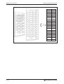
Table 4-3 shows how binary input signals are encoded to address the point table entries.
Digital Input Signals
DI7
DI6
DI5
DI4
DI3
DI2
DI1
DI0
Selected Point
Table Entry
0
0
0
0
0
0
0
1
1
0
0
0
0
0
0
1
0
2
0
0
0
0
0
0
1
1
3
0
0
0
0
0
1
0
0
4
·
·
·
·
·
·
·
·
·
·
·
·
·
·
·
·
·
·
·
·
·
·
·
·
·
·
·
1
1
1
1
1
1
1
0
254
1
1
1
1
1
1
1
1
255
Table 4-3: Selection of point table entries with digital input signals
In the factory default configuration the incremental system is activated, which means that the
absolute position detection system is turned off (PA03 “absolute position detection system”).In
this mode the current position is not stored when the power is turned off and you must thus perform a home position return every time the amplifier is powered on. The default configuration
also uses absolute target positions (PA01 “positioning control mode”).
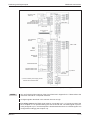
No.
Code
Function
PA01 햲
*STY
Positioning control 0: Absolute target position values
mode
1: Incremental target position values
Description
PA03 햲
*ABS
Absolute position
detection system
0: Incremental system (absolute detection off)
1: Absolute position detection system on
PA05 햲
*FTY
Feed length multiplication factor
Needed here to scale the home position value to the physical coordinate system when a home position offset (shift) has been set.
Parameter
value
Multiplication
factor STM
Range of the target
position values
0
1
−999.999 .. +999.999
1
10
−9999.99 .. +9999.99
2
100
−99999.9 .. +99999.9
3
1000
−999999 .. +999999
Table 4-4: Parameter reference
햲
MR-J3-T
To activate this parameter you must switch the amplifier power off and on again.
4 - 23
Configuration for Positioning
Positioning with Digital Inputs
The following example shows some typical configuration settings used for many common positioning applications:
Procedure:
햲 Select the incremental system for positions with PA03 *ABS.
햳 Select absolute value command mode for target positions with PA01 *STY.
햴 Set a multiplication factor with PA05 *FTY = 1 => 10 times factor.
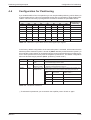
This gives us the following position system:
Min. absolute value
−9999.99
0
Max. absolute value
+9999.99
Range of possible position values
in [10STM µm]
Fig. 4-13: Effective range of the position values with the sample settings
�
Parameter settings for example
�
Fig. 4-14: Relevant parameters affecting the target position setpoint values
NOTE
4 - 24
If target positions are entered using the incremental system it is not possible to change the
rotation direction via the point table. In this mode the rotation direction can only be changed
with the start commands (ST1/ST2).
MITSUBISHI ELECTRIC
Positioning with Digital Inputs
Configuration for Positioning
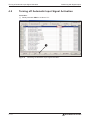
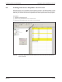
햵 The point table entries for the individual positioning steps are configured in the columns
numbered � to � in the point table list shown below.
�
�
�
�
Fig. 4-15: Example of a positioning application with 8 positioning steps
Tips for editing point table entries:
쎲 The value in the Aux. Func. column should normally always be zero. Otherwise the system
will automatically jump to the next entry in the table and execute the next positioning command after completing a positioning step, even if there is no change in the input signals.
쎲 The Dwell Time column can be used to insert a delay between reaching the target position
of the positioning step for the current table line and continuing to the next table line. This
option should only be used when multiple positioning steps are performed automatically,
without changes in the input signals.
쎲 The button Insert inserts a new line above the selected table line. Delete deletes the selected line.
쎲 The Verify function checks whether the positioning table in MR Configurator matches the
table stored in the connected servo amplifier. If the tables don't match a message is displayed showing the line number where the difference was found:
Number of table line
where tables in amplifier
and MR-Configurator do
not match
MR-J3-T
4 - 25
Configuration for Positioning
Positioning with Digital Inputs
쎲 Always deactivate start command ST1/ST2 before starting a new positioning sequence.
Then you can select a new table entry with DI0 - DI7 and start the positioning sequence
with ST1/ST2.
쎲 Table entries are not reset when you restore the amplifier's factory default settings!
쎲 You do not need to turn the amplifier off and on again after changing table entries.
NOTE
4.4.1
Please see the instruction manual for full details on all these procedures.
Importing and exporting point tables
There are two different ways to store the point table from your project so that you can edit it again
later in external programs and MR Configurator:
쎲 Export the point table as a text file with the extension .ptb. This creates a plain text file that
can be edited with a normal text editor.
쎲 Export the point table as a file with the extension .csv. These files contain data that can be
edited by spreadsheet programs like Microsoft Excel.
Procedure:
햲 The Point Table List window must be open and active.
햳 How to export the point table to a file:
�
�
�
Fig. 4-16: Exporting the point table to a file for archival or editing
4 - 26
MITSUBISHI ELECTRIC
Positioning with Digital Inputs
Configuration for Positioning
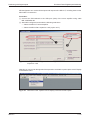
햴 How to open/import a point table data file:
�
�
Fig. 4-17: Opening a point table file to import the data
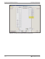
Fig. 4-18: Point table position data imported from a .csv file
MR-J3-T
4 - 27
Functional Test of Digital Input Positioning
4.5
Positioning with Digital Inputs
Functional Test of Digital Input Positioning
Normally you need a simple controller to set the digital inputs used to select the point table position entries, for example a PC, a mini PLC or an HMI control terminal. This chapter explains how
you can perform a thorough check of the functionality of the positioning control functions without
needing to perform the additional work of programming and installing a controller.
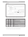
Fig. 4-19 shows a test installation without an external controller. Note that the FX Simulation Box
used in this setup can set a maximum of 14 digital inputs.
Servo motor
1-phase
200–230V AC
Motor
Encoder
Encoder cable
PC
� MR-J3USBCBL3M
Cable length: 3m
� MR-J2CMP2
� MR-J2M-CNT1TBL-M
Cable length: 0.5–1m
� MR-TB50
FX Simulation Box
24V DC
Fig. 4-19:
NOTE
4 - 28
24V DC
power supply
Test setup for simulating positioning with digital inputs
The test setup shown above does not use any safety features for the tests (EMG. OFF). You
should thus only use this setup in a controlled test environment where errors cannot cause
any danger for personnel or equipment!
MITSUBISHI ELECTRIC
Positioning with Digital Inputs
Functional Test of Digital Input Positioning
MR Configurator can monitor all the inputs and outputs of the MR-J3-T, including those on the
MR-J3-D01 I/O extension.
Procedure:
햲 Connect the PC/notebook to the USB port (CN5) of the servo amplifier using cable
MR-J3USBCBL3M.
햳 Start MR Configurator and make the following selections:
– Select the MR-J3-T series amplifier.
– Select the MR-J3-D01 expansion card (“option unit”).
�
�
Fig. 4-20: Settings in MR Configurator for checking the MR-J3-T with the MR-J3-D01
expansion card
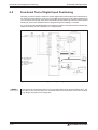
After this you can monitor the signals of the expansion card with the option Option unit I/F display
in the Monitor menu.
Fig. 4-21: Selection of the “Option unit I/F display” terminal monitor option
MR-J3-T
4 - 29
Functional Test of Digital Input Positioning
Positioning with Digital Inputs
Fig. 4-22: The “Option unit I/F display” terminal monitoring window
4 - 30
MITSUBISHI ELECTRIC
Positioning via a CC-Link Network
5
Additional Connections
Positioning via a CC-Link Network
As an alternative to using digital signals you can also control positioning with MR-J3-T servo
amplifiers via a CC-Link network connection.
NOTE
5.1
Before proceeding ensure that the MR-J3-D01I/O expansion card is not installed. If it is installed CC-Link communications will be disabled.
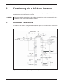
Additional Connections
In addition to the minimum configuration described in chapter 3.1 you also need to connect the
CC-Link cable and the cabling for connector CN6 for this mode.
EMG. OFF OFF
ON
Servo motor
Servo amplifier
1-phase
200–230V AC
Motor
Encoder cable
Encoder
24V DC
EMG. OFF
24V DC ±10%
150mA
Alarm
24V DC
24V DC ±10%
800mA
CC-Link
module
Servo ON
Fig. 5-1:
MR-J3-T
CC-Link cable
V1.10 compatible
Connections for operating the servo amplifier via a CC-Link network
5 - 31
Additional Connections
Positioning via a CC-Link Network
Connections for the CC-Link network
CC-Link
Master module
(e.g. QJ61BT11N)
Fig. 5-2:
NOTE
5 - 32
MR-J3-T
Connections between the servo amplifier and the CC-Link master module
You must install a terminating resistor on terminals DB and DB on the physical first and last
stations in the CC-Link network. The required ohmage of the resistor depends on the cable
length, please check the version V1.10 specifications for details.
MITSUBISHI ELECTRIC
Positioning via a CC-Link Network
CC-Link Communication Settings
5.2
CC-Link Communication Settings
5.2.1
Settings on the servo amplifier
In the instructions below we are assuming that you have an operating CC-Link network with the
following specifications:
쎲 Data rate 156Kbit/s
쎲 The master station is a QJ61BT11N module that is integrated in a System Q controller platform with a Q02H-CPU.
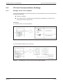
Procedure:
햲 Set the number of reserved stations:
1 reserved station
Factory default
setting
S1
2 reserved stations
Fig. 5-3:
Correct position of switch S1 for setting the number of reserved stations
햳 Set the station address (max. value 64):
x1
x10
higher values
lower values
address digits
Fig. 5-4:
MR-J3-T
Set switches x1 and x10 to the correct station address
5 - 33
CC-Link Communication Settings
Positioning via a CC-Link Network
햴 Set the data rate:
Mode
Fig. 5-5:
NOTE
5 - 34
Baud rate
Mode switch setting for the network data rate
The servo amplifier settings required for point table positioning are described in chapters 4.2
through 4.4. Please check that these settings have been made correctly before proceeding.
MITSUBISHI ELECTRIC
Positioning via a CC-Link Network
5.2.2
CC-Link Communication Settings
Configuration for communication with GX IEC Developer
Generally, positioning control is performed via a CC-Link network in applications where an additional PLC system is used for automation tasks as well as the integrated controller in the amplifier. In this example we will thus only provide detailed descriptions of the settings required to
integrate the servo amplifier in your project.
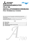
Procedure:
How to open an existing project in GX IEC Developer:
햲 Select Network � in the project directory tree in the left window.
햳 Select CC-Link � in the Network Parameter box.
햴 This opens the window Network parameters: Setting the CC-Link list where you can now
enter the settings shown in Fig. 5-6 �.
�
(a)
(b)
�
�
(c)
Fig. 5-6:
MR-J3-T
Settings required in GX IEC Developer for CC-Link communication between
the controller and the servo amplifier
5 - 35
CC-Link Communication Settings
Positioning via a CC-Link Network
Notes on the network settings:
(a) In the example only one servo amplifier is connected to the CC-Link network. This value must
be increased by the number of slave stations installed if applicable.
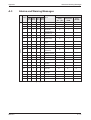
(b) These values specify which bits or data words are to be used to control the servo amplifier.
The settings shown in the example are for the following assignments:
PLC -> Servo Amplifier
Servo Amplifier -> PLC
PLC I/Os
Registers
Signals
PLC I/Os
Registers
Signals
Y100
RYn0
SON
X100
RXn0
RD
Y101
RYn1
ST1
X101
RXn1
INP
Y102
RYn2
ST2
X103
RXn3
ZP
Y103
RYn3
DOG
X11A
RX(n+1)A
ALM
Y104
RYn4
LSP
Y105
RYn5
LSN
Y106
RYn6
MD0
Y10A
RYnA
DI0
Y10B
RYnB
DI1
Y10C
RYnC
DI2
Y10D
RYnD
DI3
Y10E
RYnE
DI4
Y10F
RYnF
RES
NOTE:
Signals DI5, DI6 and DI7 are only available
when the amplifier is configured to occupy 2
stations in the network.
Table 5-1: Signal assignments
(c) Slave station type setting:
Fig. 5-7:
This configuration also enables exchange of data words
햵 Connect the PC to the PLC and transfer the modified project to the controller.
NOTE
5 - 36
If the CC-Link connection to the servo amplifier is established successfully the L.RUN, SD
und RD status LEDs on the servo amplifier will light up.
MITSUBISHI ELECTRIC
Positioning via a CC-Link Network
5.3
Testing the Servo Amplifier via CC-Link
Testing the Servo Amplifier via CC-Link
Before proceeding it is a good idea use the monitoring function in GX IEX Developer to check
that the individual servo functions can be started correctly (e.g. return to home, positioning).
After this you can then test the correct operation of the servo system with the PLC program.
Procedure:
햲 Activate monitoring mode.
햳 Select Entry Data Monitor in the Online menu.
햴 Enter the individual remote I/Os to be set or monitored.
�
Fig. 5-8:
MR-J3-T
The Entry Data Monitor window where you can set remote I/Os to test the
servo functions
5 - 37
Digital Signals − Quick Reference
Appendix
A
Appendix
A.1
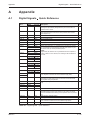
Digital Signals
Quick Reference
Connector
Pins
Signal Codes
DI/DO
CC-Link
CN6-1
EMG
–
Forced stop - emergency safety signal:
The signal is permanently assigned to this pin and must be activated for motor control.
DI
CN6-2
DOG
RYn3
Proximity dog switch:
This signal is used for some of the home position return modes.
(See chapter 4.3)
DI
CN6-3
LSP
RYn4
Forward rotation stroke end switch
DI
CN6-4
LSN
RYn5
Reverse rotation stroke end switch
DI
CN6-14
RD
RXn0
Servo amplifier ready
DO
CN6-15
ALM
RX(n+1)A
Alarm, signals a servo error
DO
CN6-16
ZP
RXn3
Home position return completed successfully
DO
CN10-1
DI0
RYnA
Select point table entry, i.e. activate a line in the table for positioning. Combinations of signals DI0 through DI7 (see Table 4-3) can
be used to selec up tot 256 positioning steps.
DI
Point table entry no.1
CN10-2
DI1
RYnB
Point table entry no. 2
CN10-3
DI2
RYnC
Point table entry no. 3
CN10-4
DI3
Description
NOTE:
Signals DI5, DI6 and DI7 are only available when the amplifier occupies 2 stations in the network, thus making 64 bits available via
CC-Link.
RYnD
DI /
DO
DI
DI
DI
Point table entry no. 4
CN10-5
DI4
RYnE
DI
Point table entry no. 5
CN10-6
DI5
RY(n+2)3
DI
Point table entry no. 6
CN10-7
DI6
RY(n+2)4
DI
Point table entry no. 7
CN10-8
DI7
RY(n+2)5
DI
Point table entry no. 8
CN10-13
DICOM
–
Connection for an external power supply for the digital control termi- DI
nals. Negative connection for source interface logic (PNP).
SON
RYn0
SERVO ON:
Activating the SON signal powers on the base circuit and makes
the amplifier ready for operation.
DI
Digital output signals for encoded error messages (see Appendix
A.3)
DO
DI
CN10-14
CN10-21
CN10-22
ACD0
–
CN10-23
ACD1
–
CN10-24
ACD2
–
CN10-25
ACD3
–
CN10-26
RES
RY1A
Reset for error messages
CN10-32
MD0
RYn6
DI
Switch between automatic/manual mode:
The MD0 signal must be off for opertion in jog mode. The signal
must be activated before starting a home position return or positioning.
CN10-35
ST1
RYn1
Start signal for forward rotation
DI
CN10-36
ST2
RYn2
Start signal for reverse rotation
DI
CN10-37
DOCO
–
Connection for an external power supply for the digital control termi- DI
nals. Positive connection for source interface logic (PNP).
CN10-49
INP
RXn1
IN Position: Target position reached signal.
DO
Table A-1: Digital signals - quick reference
MR-J3-T
A - 39
Standard Parameters − Quick Reference
A.2
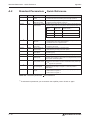
Standard Parameters
Quick Reference
No.
Code
Function
Description
PA01 햲
*STY
Positioning control
mode
0: Absolute value command system for target positions
1: Incremental value command system for target positions
PA03 햲
*ABS
Absolute position
detection system
0: Incremental system (absolute position detection off)
1: Absolute position detection system on
PA05 햲
*FTY
Feed length multipli- Needed here to scale the home position value to the physical cocation factor
ordinate system when a home position offset (shift) has been set.
Parameter
value
Multiplication Range of the target
factor STM
position values
0
1
−999.999 ... +999.999
1
10
−9999.99 ... +9999.99
2
100
−99999.9 ... +99999.9
PA14 햲
*POL
Servo motor rotation Motor rotation direction (looking at shaft end facing motor):
direction
0: Anticlockwise when ST1 signal is active
1: Clockwise when ST1 signal is active
PC02 햲
*ZTY
Home position return mode
Selects mode to be used for home position return:
0: Proximity dog mode
PC03 햲
*ZDIR
Home position return direction
0: Incrementing counting of encoder pulses
1: Decrementing counting of encoder pulses
PC04
ZRF
Home position return speed
Sets home position return speed until first detection of the
Z-phase in [rpm].
PC05
CRF
Creep speed
Speed for precise movement to home position in [rpm]
PC06
ZST
Home position
offset (shift)
Distance between the encoder home position (Z-phase) and the
physical home position in [µm]. Does not change the zero point of
the physical coordinate system.
PC07 햲
*ZPS
Home position return position value
The home position return stops when the Z-phase position is
reached.You can enter a non-zero coordinate for this position [in
10STMµm] with this parameter.
PD01 햲
*DIA1
Automatic activation This parameter configures the amplifier to automatically set the
of input signals
digital signals internally to a logical "1" when the power is
switched on.
PD01 햲
*DIAB
Polarity of the input
signal
Table A-2: Standard parameters
햲
A - 40
Appendix
Logical value for detection of the proximity dog signal (DOG):
0: Active DOG on logical "0"
1: Active DOG on logical "1"
quick reference
To activate this parameter you must switch the amplifier power off and on again.
MITSUBISHI ELECTRIC
Appendix
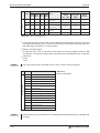
A.3
Alarms and Warning Messages
Alarms and Warning Messages
Alarm Code
Alarm Reset
Alarme
Display ACD3 ACD2 ACD1 ACD0 Error
(Bit 3) (Bit 2) (Bit 1) (Bit 0)
Power
Supply
OFF
ON
MRConfigurator/
HMI
Reset
(RES)
A10
0
0
1
0
Undervoltage
✔
✔
✔
A12
0
0
0
0
Memory error 1
✔
—
—
A13
0
0
0
0
Clock error
✔
—
—
✔
—
—
A15
0
0
0
0
Memory error 2
(E²PROM)
A16
0
1
1
0
Encoder error 1
(at power on)
✔
—
—
A17
0
0
0
0
Board error
✔
—
—
A19
0
0
0
0
Memory error 2
(Flash ROM)
✔
—
—
A1A
0
1
1
0
Incorrect servo
motor
✔
—
—
A20
0
1
1
0
Encoder error 2
✔
—
—
A24
1
1
0
0
Main circuit error
✔
✔
✔
A25
1
1
1
0
Absolute position
lost/erased
✔
—
—
A30
0
0
0
1
Regenerative
braking overload
✔햲
✔햲
✔햲
A31
0
1
0
1
Overspeed
✔
✔
✔
A32
0
1
0
0
Overcurrent
✔
—
—
A33
1
0
0
1
Overvoltage
✔
✔
✔
A35
1
1
0
1
Input frequency
too high
✔
—
—
A37
1
0
0
0
Parameter error
✔
—
—
A45
0
0
1
1
Main circuit
overheat
✔햲
✔햲
✔햲
A46
0
0
1
1
Servo motor
overheat
✔햲
✔햲
✔햲
A47
0
0
1
1
Cooling fan error
✔
—
—
햲
A50
0
0
1
1
Overload 1
✔
A51
0
0
1
1
Overload 2
✔햲
햲
✔햲
✔햲
✔햲
✔
Table A-3: Error messages(1)
MR-J3-T
A - 41
Alarms and Warning Messages
Appendix
Alarm Code
Alarm Reset
Alarms
Display ACD3 ACD2 ACD1 ACD0 Error
(Bit 3) (Bit 2) (Bit 1) (Bit 0)
Power
Supply
OFF
ON
MRConfigurator/
HMI
Reset
(RES)
A52
0
1
0
1
Excessive discrepancy error
✔
✔
✔
A61
0
1
0
1
Operation alarm
✔
✔
✔
A8A
0
0
0
0
Serial communication timeout
✔
✔
✔
A8E
0
0
0
0
Serial communication error
✔
✔
✔
888
0
—
—
—
Watchdog
✔
—
—
Table A-3: Error messages (2)
햲
햳
햴
햵
Switch on the RES signal.
To reset the alarm click on the Alarm Reset button in the alarm display window in MR
Configurator. You can also reset the alarm by pressing the STOP/RESET button on the HMI
control unit.
0: OFF
1: ON
The output signal ALM is activated when an error or alarm signal is triggered.
Warning messages
NOTE
Locate and correct the cause of the error and allow the servo amplifier, the servo motor and
the regenerative braking unit to cool down for at least 30 minutes before resetting the alarm
and restarting the system for normal operation.
NOTE
A - 42
Display
Warning
A90
Home position return incomplete
A92
Battery cable disconnected
A96
Home position return error
A98
Software limit warning
A99
Stroke limit warning
A9A
Option unit input data error
A9F
Battery warning
AE0
Regenerative system overload warning
AE1
Overload warning 1
AE3
Absolute position counter error
AE6
Server emergency off warning
AE8
Cooling fan too slow
AE9
Main circuit off
AEC
Overload warning 2
AED
Output wattage exceeded
Table A-4:
Warning messages
Please see the instruction manual for more detailed descriptions of the alarm messages and
warnings.
MITSUBISHI ELECTRIC
Index
Index
A
Alarm messages
List . . . . . . . . . . . . . . . . . . . . A - 41
Automatic input signal activation
Turning off. . . . . . . . . . . . . . . . . 4 - 14
C
CC-Link communications
Settings . . . . . . . . . . . . . . . . . . 5 - 33
Connections
Minimum connections . . . . . . . . . . . 3 - 5
Creep speed . . . . . . . . . . . . . . . . . 4 - 15
D
Digital signals
Quick reference . . . . . . . . . . . . . . A - 39
DOG home position return . . . . . . . . . . 4 - 19
E
Expansion card MR-J3-D01
Installation . . . . . . . . . . . . . . . . . 2 - 3
Settings . . . . . . . . . . . . . . . . . . 4 - 23
F
Functional test . . . . . . . . . . . . . . . . . 3 - 5
CC-Link . . . . . . . . . . . . . . . . . . 5 - 37
Positioning with digital inputs . . . . . . . 4 - 28
Settings . . . . . . . . . . . . . . . . . . . 3 - 7
G
GX IEC Developer
Data communications . . . . . . .5 - 35, 5 - 37
H
Home position return . . . . . . . . . . . . . 4 - 15
I
Installation
Hardware . . . . . . . . . . . . . . . . . . 2 - 3
MR-J3-T
M
Minimum connections . . . . . . . . . . . . . 3 - 5
MR Configurator
functional check . . . . . . . . . . . . . . 3 - 10
P
Parameter
Quick reference . . . . . . . . . . . . . . 4 - 21
Pin assignments . . . . . . . . . . . . . . . . 3 - 6
Point table
configuring . . . . . . . . . . . . . . . . . 3 - 9
Point table positioning . . . . . . . . . . . . 4 - 11
Preparations . . . . . . . . . . . . . . . . 1 - 1
Positioning
Settings . . . . . . . . . . . . . . . . . . 4 - 23
via a CC-Link network. . . . . . . . . . . 5 - 31
with digital inputs . . . . . . . . . . . . . 4 - 11
Positioning table
exporting . . . . . . . . . . . . . . . . . 4 - 26
importing . . . . . . . . . . . . . . . . . 4 - 26
Positioning table entries
selecting . . . . . . . . . . . . . . . . . . 3 - 10
S
Servo amplifier
selecting . . . . . . . . . . . . . . . . . . 3 - 7
Signal assignments
Connectors CN6 and CN10 . . . . . . . . 4 - 12
Standard parameters
Quick reference . . . . . . . . . . . . . . A - 40
W
Warning messages
Reference list . . . . . . . . . . . . . . . A - 42
Z
Z-phase reference
without DOG signal . . . . . . . . . . . . 4 - 15
A - 43
MITSUBISHI ELECTRIC
HEADQUARTERS
EUROPEAN REPRESENTATIVES
MITSUBISHI ELECTRIC EUROPE B.V.
German Branch
Gothaer Straße 8
Phone: +49 (0)2102 / 486-0
Fax: +49 (0)2102 / 486-1120
MITSUBISHI ELECTRIC EUROPE B.V.
French Branch
25, Boulevard des Bouvets
Phone: +33 (0)1 / 55 68 55 68
Fax: +33 (0)1 / 55 68 57 57
MITSUBISHI ELECTRIC EUROPE B.V.
Irish Branch
Westgate Business Park, Ballymount
Kazpromautomatics Ltd.
2, Scladskaya str.
Phone: +43 (0)2252 / 85 55 20
Fax: +43 (0)2252 / 488 60
TEHNIKON
Oktyabrskaya 16/5, Off. 703-711
Phone: +371 (0)784 / 2280
Fax: +371 (0)784 / 2281
Beijer Electronics UAB
Savanoriu Pr. 187
Phone: +7 3212 / 50 11 50
Fax: +7 3212 / 50 11 50
AVTOMATIKA SEVER
Lva Tolstogo str. 7, off. 311
Phone: +375 (0)17 / 210 46 26
Fax: +375 (0)17 / 210 46 26
Koning & Hartman B.V.
Industrial Solutions
Woluwelaan 31
Phone: +370 (0)5 / 232 3101
Fax: +370 (0)5 / 232 2980
INTEHSIS srl
bld. Traian 23/1
Phone: +7 812 / 718 3238
Fax: +7 812 / 718 3239
CONSYS
Promyshlennaya st. 42
Phone: +373 (0)22 / 66 4242
Fax: +373 (0)22 / 66 4280
Beijer Electronics AS
Postboks 487
Phone: +7 812 / 325 36 53
Fax: +7 812 / 325 36 53
Electrotechnical Systems Siberia
Derbenevskaya st. 11A, Office 69
Phone: +47 (0)32 / 24 30 00
Fax: +47 (0)32 / 84 85 77
Koning & Hartman B.V.
Haarlerbergweg 21-23
Phone: +7 495 / 744 55 54
Fax: +7 495 / 744 55 54
STC DRIVE TECHNIQUE
Poslannikov per. 9, str 1
Phone: +31 (0)20 / 587 76 00
Fax: +31 (0)20 / 587 76 05
MPL Technology Sp. z o.o.
Ul. Krakowska 50
Phone: +7 495 / 790 72 10
Fax: +7 495 / 790 72 12
Phone: +359 (0)2 / 97 44 05 8
Fax: +359 (0)2 / 97 44 06 1
INEA CR d.o.o.
Losinjska 4 a
Phone: +39 039 / 60 53 1
Fax: +39 039 / 60 53 312
MITSUBISHI ELECTRIC CORPORATION
Office Tower “Z” 14 F
Phone: +385 (0)1 / 36 940 - 01/ -02/ -03
Fax: +385 (0)1 / 36 940 - 03
AutoCont Control Systems, s.r.o.
Jelinkova 59/3
Tokyo 104-6212
Phone: +81 3 622 160 60
Fax: +81 3 622 160 75
MITSUBISHI ELECTRIC EUROPE B.V.
UK Branch
Travellers Lane
Phone: +420 (0)59 / 5691 150
Fax: +420 (0)59 / 5691 199
AutoCont Control Systems, s.r.o.
Technologická 374/6
Phone: +44 (0)1707 / 27 61 00
Fax: +44 (0)1707 / 27 86 95
MITSUBISHI ELECTRIC EUROPE B.V.
Spanish Branch
Carretera de Rubí 76-80
Phone: +420 595 691 150
Fax: +420 595 691 199
B:TECH, a.s.
Na Ostrove 84
Phone: +34 93 / 565 3131
Fax: +34 93 / 589 1579
MITSUBISHI ELECTRIC AUTOMATION
500 Corporate Woods Parkway
Phone: +420 (0)569 / 408 841
Fax: +420 (0)569 / 408 889
B:TECH, a.s.
Headoffice
U Borové 69
Phone: +1 847 478 21 00
Fax: +1 847 478 22 83
USA
EURASIAN REPRESENTATIVES
Beijer Electronics SIA
Vestienas iela 2
Phone: +32 (0)2 / 257 02 40
Fax: +32 (0)2 / 257 02 49
AKHNATON
4 Andrej Ljapchev Blvd. Pb 21
Phone: +353 (0)1 4198800
Fax: +353 (0)1 4198890
MITSUBISHI ELECTRIC EUROPE B.V.
Italian Branch
Viale Colleoni 7
EUROPEAN REPRESENTATIVES
GEVA
Wiener Straße 89
Phone: +420 569 777 777
Fax: +420 569 777 778
Beijer Electronics A/S
Lautruphoj 1-3
Phone: +45 (0)70 / 26 46 46
Fax: +45 (0)70 / 26 48 48
Beijer Electronics Eesti OÜ
Pärnu mnt.160i
Phone: +372 (0)6 / 51 81 40
Fax: +372 (0)6 / 51 81 49
Beijer Electronics OY
Jaakonkatu 2
Phone: +358 (0)207 / 463 500
Fax: +358 (0)207 / 463 501
UTECO A.B.E.E.
5, Mavrogenous Str.
Phone: +30 211 / 1206 900
Fax: +30 211 / 1206 999
MELTRADE Ltd.
Fertő utca 14.
Phone: +36 (0)1 / 431-9726
Fax: +36 (0)1 / 431-9727
Phone: +48 (0)12 / 630 47 00
Fax: +48 (0)12 / 630 47 01
Sirius Trading & Services srl
Aleea Lacul Morii Nr. 3
Phone: +40 (0)21 / 430 40 06
Fax: +40 (0)21 / 430 40 02
CRAFT Consulting & Engineering d.o.o.
Toplicina str.4 lok 6
Phone: +381 (0)18 / 292-24-4/5 , 523 962
Fax: +381 (0)18 / 292-24-4/5 , 523 962
INEA SR d.o.o.
Karadjordjeva 12/260
Phone: +381 (0)26 / 617 163
Fax: +381 (0)26 / 617 163
CS MTrade Slovensko, s.r.o.
Vajanskeho 58
MIDDLE EAST
REPRESENTATIVE
Sherf Motion Techn. Ltd.
Rehov Hamerkava 19
Phone: +972 (0)3 / 559 54 62
Fax: +972 (0)3 / 556 01 82
AFRICAN REPRESENTATIVE
CBI Ltd.
Private Bag 2016
Phone: + 27 (0)11 / 928 2000
Fax: + 27 (0)11 / 392 2354
Phone: +421 (0)33 / 7742 760
Fax: +421 (0)33 / 7735 144
INEA d.o.o.
Stegne 11
Phone: +386 (0)1 / 513 8100
Fax: +386 (0)1 / 513 8170
Beijer Electronics Automation AB
Box 426
Phone: +46 (0)40 / 35 86 00
Fax: +46 (0)40 / 35 86 02
ECONOTEC AG
Hinterdorfstr. 12
Phone: +41 (0)44 / 838 48 11
Fax: +41 (0)44 / 838 48 12
GTS
Darulaceze Cad. No. 43 KAT. 2
Phone: +90 (0)212 / 320 1640
Fax: +90 (0)212 / 320 1649
CSC Automation Ltd.
15, M. Raskova St., Fl. 10, Office 1010
Phone: +380 (0)44 / 494 33 55
Fax: +380 (0)44 / 494-33-66
MITSUBISHI
ELECTRIC
FACTORY AUTOMATION
Mitsubishi Electric Europe B.V. /// FA - European Business Group /// Gothaer Straße 8 /// D-40880 Ratingen /// Germany
Tel.: +49(0)2102-4860 /// Fax: +49(0)2102-4861120 /// [email protected] /// www.mitsubishi-automation.com
Specifications subject to change /// Art. no. XXXXXX-A /// 12.2007