1
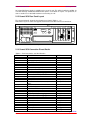
Seanet SCU System Operator & Installation Manual For Seanet SCU with Windows XP and Seanet software installed The electronic version of this document is the controlled copy. Therefore all printed versions of this document are uncontrolled. For the latest manual revision always visit – www.tritech.co.uk Supplied by Issue 6 TIL – Eng – Spec – 043 Seanet System OIM COPYRIGHT © Tritech International Ltd The copyright in this document is the property of Tritech International Limited. The document is supplied by Tritech International Limited on the understanding that it may not be copied, used, or disclosed to others except as authorised in writing by Tritech International Limited. Tritech International Limited reserved the right to change, modify and update designs and specifications as part of their ongoing product development programme. F063.1 Tritech International Ltd Seanet System OIM Table of Contents Handling of Electrostatic-Sensitive Devices ..................................................................................5 Safety Statements .............................................................................................................................7 Technical Support .............................................................................................................................7 SECTION 1..........................................................................................................................................8 1.1 General Overview ...................................................................................................................8 1.2 Seanet SCU Specification...........................................................................................................9 1.2.1 Seanet SCU Front Panel Layout ............................................................................................9 2.1 Installation & Configuration Details ........................................................................................10 2.1.1 Seanet SCU Connections.....................................................................................................10 2.1.2 Seanet SCU Rear Panel Layout ...........................................................................................11 2.1.3 Seanet SCU Connection Pinout Details ...............................................................................11 2.2 Seanet SCU Communication Configuration ...........................................................................12 2.2.1 AIF Card details ....................................................................................................................12 2.2.2 Subsea Sensor Electrical Installation ..................................................................................12 2.2.3 ST Head Subsea Interconnect Cabling ................................................................................13 2.2.4 ArcNet Line Termination........................................................................................................13 SECTION 3........................................................................................................................................15 3.1 General Information & Operating details ................................................................................15 3.2 Seanet System Display .............................................................................................................15 SECTION 4........................................................................................................................................16 4.1 Maintenance...............................................................................................................................16 4.1.1 ESD / Transient Protection (COM Port 1 )............................................................................16 4.1.2 Front Air Inlet Filter ...............................................................................................................16 4.2 Trouble Shooting.......................................................................................................................17 SECTION 5........................................................................................................................................18 5.1 System Software Configuration...............................................................................................18 5.1.1 Seanet System Re-Installation .............................................................................................18 5.1.2 Repair of Seanet Pro ............................................................................................................18 5.1.3 Full Disk Re-Installation from 'Emergency Backup' ZIP® Disk .............................................19 5.2 Configuring Video Output ........................................................................................................20 APPENDIX 1 : AIF – ACOUSTIC INFORMATION CARD ..............................................................22 Appendix 1-1. AIFV4 - ISA Version ................................................................................................23 I) AIFV4 ISA Card Hardware settings ............................................................................................23 II) AIFV4 ISA Diagnostic Led's ......................................................................................................24 III) V4AIF ISA Interrupt and I/O Base Card Address .....................................................................24 IV) AIFV4 ISA Connector Details...................................................................................................25 AIFV4 ISA Connector Details (cont.) .............................................................................................26 AIFV4 ISA Connector Details (cont.) .............................................................................................27 Appendix 1-2. AIFV4 - PCI version ................................................................................................28 I) AIFV4 PCI Card Hardware settings............................................................................................28 II) AIFV4 PCI Diagnostic Led's ......................................................................................................29 III) V4AIF PCI Card resources .......................................................................................................29 IV) AIFV4 PCI Connector Details...................................................................................................30 AIFV4 PCI Connector Details (cont.) .............................................................................................31 AIFV4 PCI Connector Details (cont.) .............................................................................................32 Issue 6 TIL – Eng – Spec – 043 Page 4 of 32 Tritech International Ltd Seanet System OIM Handling of Electrostatic-Sensitive Devices Attention Observe Precautions for handling Electrostatic Devices Caution Handling of Electrostatic-Sensitive Devices Certain semiconductor devices used in the equipment are liable to damage due to static voltages. Observe the following precautions when handling these devices in their unterminated state, or sub-units containing these devices: • Persons removing sub-units from any equipment using electrostatic sensitive devices must be earthed by a wrist strap via a 1MΩ resistor to a suitable discharge reference point within the equipment. • Soldering irons used during any repairs must be low voltage types with earthed tips and isolated from the Mains voltage by a double insulated transformer. Care should be taken soldering any point that may have a charge stored. • Outer clothing worn must be unable to generate static charges. • Printed Circuit Boards (PCBs) fitted with electrostatic sensitive devices must be stored and transported in appropriate anti-static bags/containers. F110.0 Issue 6 TIL – Eng – Spec – 043 Page 5 of 32 Tritech International Ltd Seanet System OIM Warranty Statement Tritech International Limited herein after referred to as TIL TIL warrants that at the time of shipment all products shall be free from defects in material and workmanship and suitable for the purpose specified in the product literature. The unit/system warranty commences immediately from the date of customer acceptance and runs for a period of 365 days. Customer acceptance will always be deemed to have occurred within 72 hours of delivery. Note: Any customer acceptance testing (if applicable) must be performed at either TIL premises or at one of their approved distributors unless mutually agreed in writing prior to despatch. Conditions: These include, but are not limited to, the following: 1 The warranty is only deemed to be valid if the equipment was sold through TIL or one of its approved distributors. 2 The equipment must have been installed and commissioned in strict accordance with approved technical standards and specifications and for the purpose that the system was designed. 3 The warranty is not transferable, except or as applies to Purchaser first then to client. 4 TIL must be notified immediately (in writing) of any suspected defect and if advised by TIL, the equipment subject to the defect shall be returned by the customer to TIL, via a suitable mode of transportation and shall be freight paid. 5 The warranty does not apply to defects that have been caused by failure to follow the recommended installation or maintenance procedures. Or defects resulting from normal wear & tear, incorrect operation, fire, water ingress, lightning damage or fluctuations in vehicles supply voltages, or from any other circumstances that may arise after delivery that is out with the control of TIL. (Note: The warranty does not apply in the event where a defect has been caused by isolation incompatibilities.) 6 The warranty does not cover the transportation of personnel and per diem allowances relating to any repair or replacement. 7 The warranty does not cover any direct, indirect, punitive, special consequential damages or any damages whatsoever arising out of or connected with misuse of this product. 8 Any equipment or parts returned under warranty provisions will be returned to the customer freight prepaid by TIL 9 The warranty shall become invalid if the customer attempts to repair or modify the equipment without appropriate written authority being first received from TIL. 10 TIL retains the sole right to accept or reject any warranty claim. 11 Each product is carefully examined and checked before it is shipped. It should therefore be visually and operationally checked as soon as it is received. If it is damaged in anyway, a claim should be filed with the courier and TIL notified of the damage. Note: TIL reserve the right to change specifications at any time without notice and without any obligation to incorporate new features in instruments previously sold. Note: If the instrument is not covered by warranty, or if it is determined that the fault is caused by misuse, repair will be billed to the customer, and an estimate submitted for customer approval before the commencement of repairs. F167.1 Issue 6 TIL – Eng – Spec – 043 Page 6 of 32 Tritech International Ltd Seanet System OIM Safety Statements Caution! Throughout the manual certain safety or operational related comments and requirements will be highlighted to the operator by indications identified by the adjacent symbol and text. Technical Support Contact your local agent or Tritech International Ltd Mail Tritech International Ltd. Peregrine Road, Westhill Business Park, Westhill, Aberdeen, AB32 6JL, UK Telephone ++44 (0)1224 744111 Fax ++44 (0)1224 741771 Email [email protected] Web www.tritech.co.uk An out-of-hours emergency number is available by calling the above telephone number If you have cause to use our Technical Support service, please ensure that you have the following details at hand prior to calling: • • • System Serial Number (if applicable) Fault Description Any remedial action implemented Due to the expansion of equipment capabilities and the fact that new sub-modules are continually being introduced, this manual cannot detail every aspect of the operation. The name of the organisation which purchased this system is held on record at Tritech International Ltd. Details of new software and hardware packages will be announced at regular intervals. Depending on the module, free upgrades will be offered in keeping with our policy of maintaining the highest levels of customer support. Tritech International Ltd can only undertake to provide software support for systems loaded with Operating System and Tritech Seanet software in accordance with the instructions given in the System Re-installation section of this manual. It is the customers responsibility to ensure the compatibility of any other package that they may choose to load unless with the prior consent of Tritech. Issue 6 TIL – Eng – Spec – 043 Page 7 of 32 Tritech International Ltd Seanet System OIM SECTION 1 1.1 GENERAL OVERVIEW The SEANET SCU was introduced on the market in January 2002 as a direct replacement for the SeaKing SCU which is now a discontinued product. The SEANET SCU has all the features of the SeaKing SCU with added options and capabilities for future expansion. The system uses modern PC technology housed in a semi-rugged anodised Aluminium housing and incorporates a sophisticated front panel Remote Access Terminal (RAT) which enables all functions to be controlled by a combination of trackball and function button operations. The SEANET Surface Control Unit (SCU) is designed to control and display the complete range of SeaKing subsea sensors and incorporates a number of very important features. • Versatility The SEANET SCU can simultaneously run combinations of Imaging Sonar, Profiling Sonar, Bathymetric & Oceanographic package and Sidescan together. • High speed communication The SEANET SCU uses a very fast ArcNet communications to the subsea devices allowing a standard data rate of 156kBaud (max cable length 1200m) with options for fibre-optic interfaces and other Baud rates available for longer cable lengths. • Display resolution The SEANET SCU is able to run on a SVGA monitor at up to 1280 x 1024* screen resolution. The Seanet operating software will run on any number of display colours – this is a marked improvement on the SONV3 revision of software which required a fixed 256-colour display setting. * For clarity, a resolution of 800 x 600 is recommended. • Digital recording of data The SEANET SCU is installed with a high capacity ZIP® drive that can be used to record and replay back all data from subsea sensors such as SeaKing DFS Sonar, DFP Profiler, Sidescan and Bathy. The floppy drive is also available for recording shorter log files. As well as sonar data, other data including NMEA 1083 may be recorded. • Solid State Boot Drive All Operating System and Sensor Control software are installed on a solid state Flash card which is faster and more shock-resistant than mechanical platter disks. Full re-installation in just minutes from a bootable 'Emergency Backup' ZIP® disk. • RS-232 Interfaces for survey data All data collected by the subsea devices can be made available on one or more RS-232 ports for survey purposes. The XPE SEANET SCU has 1 motherboard COM port built in for this purpose with a further 2 ports on an internal Auxiliary I/O card. (Note on earlier models which have 2 motherboard ports, the Aux I/O card is an option) • Downloading software to subsea sensors All SeaKing subsea sensor software is stored in Flash RAM that enables the head to have its software upgraded without dismantling the unit and replacing EPROM’s etc. • 19" Rack Mount The SEANET SCU is designed to be rack-mountable in Racks of depth 330mm or greater. • Expansion and connectivity The XPE Seanet SCU has a 10/100 base-T Ethernet card fitted as standard and USB 2.0 connections to facilitate data storage and transfer using network or external storage drives. Issue 6 TIL – Eng – Spec – 043 Page 8 of 32 Tritech International Ltd Seanet System OIM 1.2 SEANET SCU SPECIFICATION Processor Intel™ Pentium Operating System Microsoft Windows XP Primary Control PS/2 Remote Access Terminal (RAT) Video Output (1) SVGA, XGA or SXGA Video Output (2) Composite and S-VHS PAL/NTSC ArcNet Link 1 x 156kbit/sec (1500m) or 78kbit/sec (2500m) Storage Media 3.5” Floppy & 250MB Zip Interface Ports 1 (+ 2) x RS-232 (electrically protected COM ports) 1 x Keyboard (PS/2) 1 x Mouse (PS/2) 1 x Parallel Port (Centronics) 1 x 24VDC @ 24VA Output (for equipment test purposes) 4 x USB 2.0 port 1 x Ethernet (10/100 Base-T) Input Voltage 110/220VAC 50/60Hz @ 50VA Weight 12kg Material Aluminium, Stainless Steel Operating Temperature 0 to 40 deg C Storage Temperature -20 to 50 deg C Options Composite Video Input Barometric Pressure Sensor Internal HDD 1.2.1 Seanet SCU Front Panel Layout 132.5 mm 482.6 mm Fig. 1.1 SEANET SCU Front Panel Layout (complete with Rev.2 RAT as shown) The particular RAT controls depend on the particular subsea sensors fitted, and the user should refer to the appropriate section of the manual for full details of operation. Issue 6 TIL – Eng – Spec – 043 Page 9 of 32 Tritech International Ltd Seanet System OIM SECTION 2 2.1 INSTALLATION & CONFIGURATION DETAILS The SEANET SCU should be carefully removed from its transit case and checked to see that the control unit is undamaged. The unit may be inverted to check for any parts that may have been loosened during transit. If so, remove the unit cover and investigate further. The unit should be firmly mounted in a clean dry installation such as a rack system. If fitted in a confined space such as a rack, then an adequate supply of cool air should be available to keep the unit from overheating. The SEANET SCU has an internal cooling fan for sourcing and filtering the air at the front of the unit. The back of the unit must have a clear space around it, for air venting, cooling and cable access. If the unit is mounted on a desk or bench, then it should be secured against movement when powered on. Again leave access for air circulation and cable access. 2.1.1 Seanet SCU Connections The SEANET SCU is supplied to the customer with the screen display and output and communications already configured to suit their system. The user should not have to change the screen display layout or comm’s set-up unless it is not suited to their use. Contact Tritech for details. The SEANET SCU mains input (J1) should be connected to a fused (rated 5A) 110/230V 50/60Hz power supply. The mains supply to the SEANET SCU must be 'clean', free of transient noise spikes and interference, as suitable for computers and electrical instruments. If the mains supply is of a 'dirty' nature then a suitable filter or uninterruptible power supply (UPS) must be fitted. There is an On/Off Isolator switch at the rear of the unit and momentary On/Off 'soft power' switch at the front. The On/Off Isolator switch must be ON before operating the front momentary soft power switch. For the full connection details of the SEANET SCU to other parts of the system please refer to the Connection Pinout data and take particular note of (data comm's) cable termination requirements. Connect the ArcNet communication lead, for connection to the subsea device(s), to the AIF Card (J2.1). Connect the VGA output display to a suitable VGA monitor (J3.1). If Video OUT option is active then the Video Jumper lead should be connected to the Video Out port (J3.2). If the Video OUT option is used for recording or viewing, the S-VHS format provides a much better picture quality than the normal composite PAL / NTSC. If the RAT is used remotely, use the extension lead supplied to connect it to either the front of the SEANET SCU, or the back at the AIF card (J2.2). Mount the RAT in a secure safe place if not fitted to the SEANET SCU. PS/2 connections are available for Keyboard and Mouse options. If a keyboard is to be used, then this connects on to the front or rear panels. Similarly a PS/2 mouse could be used, as a backup, to replace the RAT controller if this is ever necessary. A PS/2 mouse will connect on the front or rear panels and by simply re-powering the SCU this will force it to be detected and loaded by Windows. For Remote Profiler operations the SEANET SCU will have to be linked to another computer, use the RS-232C I/O connections for this on the rear (COM1 on the main rear panel and COM5 and COM 6 in the expansion slot). These I/O ports are surge protected and opto-isolated. Before powering up the SEANET SCU check that the subsea heads are correctly connected, check the data communication lines for shorts to other wires, and check the termination resistance is correct at both ends. See Subsea Interconnect Cabling, ArcNet Line Termination and installation notes for more details. Issue 6 TIL – Eng – Spec – 043 Page 10 of 32 Tritech International Ltd Seanet System OIM An Isolated DC Power Supply is available at the rear of the unit. This will be installed as 24VDC, 1A as default although 12VDC and 36VDC Power options can be fitted on request. For protection, an auto-re-setable fuse is fitted with maximum current rating of 1.2A. 2.1.2 Seanet SCU Rear Panel Layout The connection details shown in these drawings are listed in Table1.1 - 1.5. Note that the layout of earlier and upgraded Seanet SCUs will differ from that shown below. J5 Not Fitted 1 2 3 4 J2.2 5 6 J6.2 J2.1 Slot J4.2 J2 J5.1 J7 J3.2 J1 J6.1 J4 J6 J1.2 J3.1 J1.1 J4.1 J3 7 Fig. 2.1 SEANET SCU Back Panel Layout 2.1.3 Seanet SCU Connection Pinout Details Table 2.1 Panel connections and Slot Allocation REF. DESCRIPTION J1 Mains Input 240/120V AC 1Ø J2 Mains On/Off Isolator Switch J3 DC Supply Output (0V, +24V/12 VDC) J4 Mouse J5 Keyboard J6 Earth/Ground Point J7 Barometric Input (option) TYPE IEC On-off Rocker Switch 4mm Banana Socket PS/2 PS/2 External Tab / stud J1.1 J1.2 J1.3 LPT1 Printer port PORT 1 (COM1) Data logging port (COM2 NOT FITTED) 25-way D female 9-way D male No connector SLOT 3 J3.1 J3.2 VGA / VIDEO card VGA monitor 1 connector PAL/NTSC monitor 2 connector (for interface cable) 15-way HDD female 15-way HDD female SLOT 4 J5.1 Network Card 10/100Base-T Ethernet port RJ45 SLOT 5 J4.1 J4.2 Auxilliary com Port PORT 1 (COM5) Data logging port PORT 2 (COM6) Data logging port 9-way D male 9-way D male SLOT 6 J2.1 J2.2 Sonar AIF Card Subsea Sensor Comms Aux. RAT connector 15 way D female 9-way D female SLOT 7 J6.1 J6.2 Issue 6 USB backplane USB 2.0 port USB 2.0 port USB Type A USB Type A TIL – Eng – Spec – 043 Page 11 of 32 Tritech International Ltd Seanet System OIM 2.2 SEANET SCU COMMUNICATION CONFIGURATION 2.2.1 AIF Card details The AIF interface PCB is located in slot 6 of the SCU. Full details of all the connections are contained in Appendix 1. Normal communications with the subsea devices is via a customised version of the ARCNET network system and requires a good quality balanced twisted pair cable. An optional RS-232 interface can be provided to allow telemetry connection through a fibre optic system capable of 115kBaud transmission. The RS-232 interface is available in the guise of an RS232 to ARCNET 'converter' PCB that is installed in a dry pod on the vehicle. Alternatively, an intelligent 4000m pressure rated Junction Box will provide the RS-232 interface to the network of SeaKing ARCNET devices. Note: there is a single-head RS-232 option built into SeaKing heads but this is not multi-drop. 2.2.2 SUBSEA SENSOR ELECTRICAL INSTALLATION The SeaKing range of Subsea Sensors are designed to work from a smoothed DC power supply of 18v-36v DC (Absolute Maximum 36v DC). If using a rectified transformer PSU, the output of the PSU must have a filter capacitor of not less than 470µF, for each head being powered. If an unregulated PSU is used, then make sure that the voltage value measured at the head is in the range 18-36v DC, in power on/off and running conditions. If powering the head(s) down a long lead or umbilical, the maximum recommended loop resistance of the power line must not exceed 10Ω for one head, 5Ω for two heads, and 3Ω for three heads. If the supplied voltage is less than 18v dc the head may not operate correctly. Caution! Issue 6 Never try to make SeaKing DFS system heads work down a long cable by increasing the PSU output voltage above 36v DC. Always pay particular attention to the termination of the data lines as below. If using cables in excess of 1,200m it may prove necessary to reduce the Baud rate - if in doubt contact Tritech for details. TIL – Eng – Spec – 043 Page 12 of 32 Tritech International Ltd Seanet System OIM 2.2.3 ST Head Subsea Interconnect Cabling The Standard Underwater Connector supplied is Tritech 6 way. Default telemetry is ARCNET and the wiring code for this is shown below. Note: If another telemetry option such as single node RS-232 is used, wiring details will be found in another section of the manual. Caution! The numbers shown relate to all schematic diagrams, (not a DIN style format). 1 1 6 2 2 3 3 5 4 Connector Face View 4 5 6 ARCNET-A (RS-232 Tx) ARCNET-B (RS-232 Rx) +24v DC (+24v DC) 0v DC (0v DC) (RS-232 Gnd) HEAD CHASSIS Yellow Blue Red Black Green Screen Fig 2.2 Tritech 6-Way Underwater Connector - Wiring Configuration Pin-outs for optional single-node RS-232 communications are shown in italics. Refer to the “Seanet Pro Sensor Communication Manual” for more information on RS232 configuration and baud setup. 2.2.4 ARCNET LINE TERMINATION The ArcNet communications link normally requires termination resistors to be installed at each end of the umbilical cable. These resistors are fitted between each line of the twisted pair. Mode 1. For twisted pair cables that are below 100 metres in length, it is only necessary to install one termination resistor of value between 47 to 100 ohms (68 ohms nominally). Mode 2. For twisted pair cables that are between 100 to 1200 metres in length, two termination resistors should be installed, one at either end of the cable. At the surface AIF / SKIM-100 connection point, a 270 ohm resistor should be fitted, normally inside the 15-way ‘D’ connector shell. At the subsea end of the cable, a 39 ohm resistor should be fitted – if there is more than one Sensor connected then this resistor should be fitted at the junction / splice point of the cable. Mode 3. For twisted pair cables that are between 1200m to 2500 metres, install 270 and 39 ohm resistors as per Option 2 above. (Modes 1 & 2 = Normal ArcNet Baud Rate, Mode 3 = Half ArcNet Baud Rate) Issue 6 TIL – Eng – Spec – 043 Page 13 of 32 Tritech International Ltd Seanet System OIM Fig. 2.3 ArcNet Termination Resistors 6w Underwater Connector AIF / SKIM-100 'ArcNet LAN' 8 1 15 2 39 ohm Resistor 47 - 100 ohm Resistor 270 ohm Resistor 100 - 2500 metre twisted pair cable Caution! < 100 metre twisted pair cable 8 1 15 2 AIF / SKIM-100 'ArcNet LAN' 6w Underwater Connector To operate over 1200 metres, the ArcNet Baud rate must be switched to the lower 78.1kBaud rate, this is termed the Half Baud rate. (refer to‘SeaNet Pro (Survey Data Acquisition & Logging) Software – Operator Manual’ (TIL-ENG-SPEC-078)). * …this section of the manual contains the Sensor head and AIF Card switch settings for both the Normal and 1/2 Baud operations. The default factory setting is Normal Baud operation of 156.2kBaud. Note on Subsea Termination Resistor: (as shown in diagram above) This will normally be installed in the Junction point on the vehicle where the communications pair splits off to each SeaKing device that is connected; i.e. this junction point would normally be inside the vehicle Junction box/pod. There are circumstances where it is not possible to install a permanent subsea termination resistor for the SeaKing communications; i.e. when operating over a single run of cable. In these cases, a Yellow Waterblock Adapter (Part No. 2648) is available which has a 39 ohm termination resistor installed internally. These Yellow adapters are now supplied with each SeaKing system (SCU surface unit or PC Install kit) as supplied from mid-2000 onwards. For systems purchased before this date and which do not therefore include this Yellow adapter, they can be obtained from Tritech or through a local agent. The Yellow terminated waterblock should be installed directly onto the ‘Main’ connector port on one of the SeaKing heads attached to the network (as indicated left). Important: (1) Only one yellow 39Ω terminated waterblock to be used per system. (2) Check that there are no other termination resistors present – other than 270Ω at surface – prior to installation. Issue 6 TIL – Eng – Spec – 043 Page 14 of 32 Tritech International Ltd Seanet System OIM SECTION 3 3.1 GENERAL INFORMATION & OPERATING DETAILS Once a system has been installed in conjunction with the relevant sections of this manual and the sensor manuals, it can be tested in air by powering up the system and observing that communications with the subsea device(s) is established. When the SEANET SCU and subsea heads are switched on, the system display will appear on the monitor after a few seconds delay. Until the SEANET SCU, AIF Card, Remote Access Terminal (RAT), and Subsea elements are communicating correctly, the Status Bar will display a Timeout (‘Timeout Node xx’) message for each Node that it is trying to communicate with. These messages will disappear as each subsea element checks out OK. If the RAT or subsea elements are not powered up, not present, or have a fault somewhere, then error messages will be shown in the status bar boxes on the bottom of the display. If error messages appear, check that all the system parts are connected and that all leads/cables are correctly installed. When error messages continue to appear then there is a fault and the TroubleShooting section should be referred to. The following sections of this manual will describe the general software controls in addition to installation and connection instructions. Further, separate manual sections will describe operation of each of the subsea Sensors and their connection details. 3.2 SEANET SYSTEM DISPLAY Full details of the Seanet Pro and Seanet Setup operation can be found in the Seanet Pro Users Manual. There are also a number of devices that can be connected to the Seanet SCU including Imaging Sonar, Profiler, Bathy and Sidescan. Refer to the Operator’s manual section that was supplied with each of these devices for specific details on their screen controls and functions. Issue 6 TIL – Eng – Spec – 043 Page 15 of 32 Tritech International Ltd Seanet System OIM SECTION 4 4.1 MAINTENANCE There are few user-serviceable parts inside the SEANET SCU that can be checked and/or replaced. Firstly, it is recommended that the unit be used in a clean, well ventilated and dust-free environment. Also, operating in extreme temperature and humidity should be avoided if possible. The environmental temperature should be between 0 to +40 degrees C. 4.1.1 ESD / Transient Protection (COM Port 1 ) The main RS-232 COM Port is installed with electrical surge protection. These elements are fitted on the SCU4IO PCB (P/N 5126) which is located inside the SCU at the rear. If the COM 1 Port is subjected to very high electrostatic noise or transients, the protective elements on this PCB would blow / open-circuit and therefore protect the serial UART that is installed on the main motherboard. If in the unlikely event the protection does blow on the PCB then the user has a number of options open to themselves; a) Replace the SCU4IO PCB with a spare if carried. Contact Tritech or a local agent who will supply this PCB. b) Replace the blown protective elements / components on the PCB. This would obviously require some diagnosing and know-how on the part of the user. c) As an emergency option, by-pass the PCB and connect straight through to the COM1 port on the motherboard. Caution! This is only recommended in emergencies as the UART is now unprotected and any further surges or voltage spikes may render the main motherboard inoperable. To bypass the SCU4IO PCB, remove the bottom panel on the rear of the SCU, situated under the recess where COM Port connections …etc are located. This panel is held on with 4 x screws. If COM1 is faulty, remove the ribbon cable that connects to the 9-pin male 'D' header on the main motherboard, this is UART1 (COM1). Connect your cable directly to the 'D' header on the motherboard. Caution! It is strongly advised that bypassing the protection only be used for a temporary period and that the blown protection element(s) be replaced as soon as possible. 4.1.2 Front Air Inlet Filter It is recommended that this filter be replaced annually although a replacement may be required sooner if operating the unit in a particularly dirty environment. The Tritech Part number of the air filter is 5023. Issue 6 TIL – Eng – Spec – 043 Page 16 of 32 Tritech International Ltd Seanet System OIM 4.2 TROUBLE SHOOTING Symptoms: 1. Failure to boot-up. Check that all internal boards and connectors are correctly in place and firmly secured. Particularly if the system has been recently moved or subjected to any shock loads. 2. Continuous Status "Timeout” messages. This indicates that there is no communication with the device flagged. Check the power and communications links to the Subsea Sensor for continuity and for correct polarity, voltage and ensure that the power supply can provide sufficient current to power all devices. If necessary refer to the service section to check that the head internal fuses have not blown. If this occurs on first installation pay particular attention to cable terminations and check that you are not exceeding the recommended cable length (1200m using the standard Baud rate). If a cable flood is suspected, then the conductors will need to be insulation tested; the subsea units and SEANET SCU must be disconnected. Caution! This is especially critical if a cable insulation tester is used to check resistance between conductors, as serious damage to the Scanning/Profiling heads and SEANET SCU will occur if the correct procedure is not followed. 3. Other Status Messages. Refer to the STATUS BAR Status Codes. Issue 6 TIL – Eng – Spec – 043 Page 17 of 32 Tritech International Ltd Seanet System OIM SECTION 5 5.1 SYSTEM SOFTWARE CONFIGURATION Your system will be delivered with Windows XP Embedded and Seanet System Software preinstalled. An Emergency Backup Zip Disk is provided which contains backup files for the Seanet SCU. **The disk is supplied inside the SCU secured on top of the floppy drive chassis.** There are 2 levels of restoration that can be carried out A) Reinstallation of the Seanet Pro software only to factory default. Detailed in section 6.1.2 below It is recommended where possible that this is attempted before level B in order to recover the SCU. B) Complete Re-installation of the Flash disk to factory supplied condition. Detailed in section 6.1.3 below Use of this level will erase all files currently stored on the Flash disk and replace with factory state. 5.1.1 Seanet System Re-Installation The SEANET SCU has the following Drive Letters; Drive C:\ Drive D:\ [Primary, Flash Memory boot drive where system files and SeaKing software are installed. This drive should NOT be used for storing any log files]. [The ZIP® Drive where all Log Files should be recorded. This drive is also where the ® Full System Restore from the 'Emergency Backup' Zip Disk is performed. N.B. There is an option to install a Hard Disk Drive which will normally appear with the Drive E:\ letter. 5.1.2 Repair of Seanet Pro If the SCU is booting up normally and only the Seanet software is giving a problem then, as a first level recovery, the Seanet Pro software can be re-installed from the Zip Disk Located on the Emergency Backup Zip disk are files to allow only the restoration of the Seanet Pro program. Browse the Zip Disk and locate the following folder Run the file AifSetup.exe from this folder and follow the installation prompts through. Remove the Zip disk and reboot the SCU when prompted. Issue 6 TIL – Eng – Spec – 043 Page 18 of 32 Tritech International Ltd Seanet System OIM 5.1.3 Full Disk Re-Installation from 'Emergency Backup' ZIP® Disk If any part of the Windows operating system becomes corrupt and requires re-installing, the original factory configuration can be restored from a Zip Disk in a matter of minutes. Refer to the following steps for guidance... a) Power up Seanet SCU. b) Insert Emergency Backup Zip® Disk into Zip® Drive, then press Reset button on front of SCU. ® c) The SCU should re-boot from the software on the Zip Disk and start the Image Restore program. ® Note: If this is not the case and the SCU re-boots directly into Windows, then remove the Zip Disk and restart the SCU. Enter the BIOS on restart, by pressing 'Delete', and in the 'Advanced BIOS Features' ensure the 'First Boot Device' is set to 'ZIP100'. Remember to save any changes before exiting the BIOS and then refer back from a) above. d) The 'Microsoft Windows Startup Menu' will appear. In this menu, select… '1. Restore Hard Disk to factory defaults' e) The Restore should take around 3 minutes, after which time the prompt to "remove Zip Disk and Restart computer" will appear. Press the 'Reset' button on the front of the Seanet SCU to Restart. f) A Windows license will have been allocated to the Seanet SCU by Tritech. g) On first boot up the Installation will reseal the SCU after which it will restart automatically h) On second boot up the SCU will display a log on prompt. Do not enter a password and press the <OK> button to continue. You will then be asked to re-insert the Zip Disk in order that the Seanet Pro installation can be performed. i) Subsequent boot ups will not display the log on prompt Issue 6 TIL – Eng – Spec – 043 Page 19 of 32 Tritech International Ltd Seanet System OIM 5.2 CONFIGURING VIDEO OUTPUT The SEANET SCU display can be either to an SVGA or PAL/NTSC monitor. It is possible to have 2 monitor connections operating simultaneously; SVGA + PAL or SVGA + NTSC. These features will be configured within Windows for whatever particular video card is installed, as now described… 1. Matrox Millennium G450 DualHead LX This is a combined SVGA + PAL/NTSC Video card. There are 2 x 15-pin High Density 'D' output connectors on the rear, the top connector is for SVGA output, whilst the bottom provides PAL/NTSC. If a PAL/NTSC output is configured, this will require the supplied interface cable to be connected. The interface cable connects to the bottom 'D' connector and splits off to both Composite and S-VHS plugs. SVGA + PAL/NTSC Output Connections matrox 1 SVGA Output to CRT Monitor #1 PAL / NTSC Composite Output PAL / NTSC S-VHS Output 2 To configure the PAL/NTSC Video Output option, in Windows… Note: If a network connection has been installed, ensure that you are logged on to XP as an Administrator to make changes. The factory-set Administrator should be; User = “Administrator”, Password = <blank>. 1. Right-click on the Windows desktop and select ‘Properties’ from the pop-up panel. 2. Select 'Settings' tab page and then click on 'Advanced' button. 3. To enable the PAL/NTSC Video Output, select 'DualHead' tab page and then double-click on the ‘DualHead’ clone… Issue 6 TIL – Eng – Spec – 043 Page 20 of 32 Tritech International Ltd Seanet System OIM 4. Click on the Hot Keys button to open the following panel and then expand the ‘Features’ list. Double-click on 'DualHead Clone’ to open the following panel… 5. Click on the ‘Keyboard shortcut:’ text box and then using the keyboard type the key that should be pressed at the same time as the ‘Alt’ key to enable/disable the PAL/NTSC video output. 6. Click on ‘Save’ and then ‘OK’ on the next panel. 7. Expand the ‘TV Output’ list where the output standard (PAL or NTSC) and other video settings can be configured. 8. Click on 'Apply' button to enforce all above changes and re-start the computer if prompted. 9. Connect the video interface cable, as shown above, between card and monitor cable. Use the keyboard Hot Keys (as configured in Step 5) to enable/disable the video output. Issue 6 TIL – Eng – Spec – 043 Page 21 of 32 Tritech International Ltd Seanet System OIM APPENDIX 1 : AIF – ACOUSTIC INFORMATION CARD There are 4 revisions of SeaKing AIF card; AIFBV3 – the first revision, installed in earlier SEAKING SCUs. These cards are NOT compatible with the Windows XP operating system. AIFV4 ISA – the second revision, installed in earlier SEANET SCUs (see Fig 4.2). AIFV4 PCI – the third revision, installed in current SEANET SCUs. These cards will NOT support SONV3 software AIFV4 (PC104 Layout) – Specialist revision for PC104 application. The four types of AIF card have the same functionality and communicate using ARCNET networked communications. ARCNET communications requires a screened twisted pair. The AIF card’s default comm’s and Head comm’s configuration is ARCNET, however serial interfaces are available to allow Tritech sensors to interface through fibre optic or modem systems that are capable of 156kBaud transmission. TTL, RS-232 and RS-422 are available modem interface options. Refer to this manual and the “Seanet Sensor Communications Manual” or the “Seanet TTL Fibre Optic Interface Manual” for more information on utilising different interface options. Important: This manual will only describe the AIFV4ISA and AIFV4 PCI as these are the only cards which support Seanet Pro software. Details for the PC104 card can be obtained by contacting Tritech International Ltd or their agent. Issue 6 TIL – Eng – Spec – 043 Page 22 of 32 Tritech International Ltd Seanet System OIM APPENDIX 1-1. AIFV4 - ISA VERSION I) AIFV4 ISA Card Hardware settings Internal Ribbon connection on Seanet SCU from J9 to RAT JP2 should be set +12V Rotary switches should be set SW2=3 SW1=4 LANSENS should have NO jumper fitted J4 Header should be set with INT10 shorted Fig. 4.2 AIFV4 Rev.C PCB Card Layout. Note: J5 = J2.2, J3 = J2.1 on SCU rear panel JP1 sets the output between ARCNET and TTL Note that JP1 is not shown in the above drawing. Refer to photographs below for settings JP1 in ARCNET position Issue 6 JP1 in TTL position TIL – Eng – Spec – 043 Page 23 of 32 Tritech International Ltd Seanet System OIM II) AIFV4 ISA Diagnostic Led's LED 1-4 The AIF Card has a column of diagnostic LED's situated on the back of the module between the back panel connections. These are used to check on the status of the communications channels to the systems devices. They are useful for setting up the communications lines, and when fault finding the system. See below LED 5, 6 (…& 7, 8 - Rev.C) The AIF Card also has four LED’s mounted at the upper rear edge of the PCB Module. These LEDs indicate the presence of +5v, +12v and -12v power rails to the card. The fourth LED is a diagnostic LED to indicate AIF CPU activity Aux.Rx Aux.Cts Rat.Rx Lan.Rx RED RED RED RED LED4 Aux.Tx GREEN LED3 Aux.Rts GREEN LED2 Rat.Tx GREEN LED1 Lan.En GREEN +12V -12V RED RED LED6 +5V GREEN LED5 DIAG GREEN DIAG Flashes On/Off AIF V4 (Rev.B) LED5 -12V LED6 DIAG LED7 +12V LED8 +5V RED ORANGE RED RED DIAG On when SONV3 / V3SETUP Open AIF V4 (Rev.C) LED 1-4 Aux Rx and Aux Tx LEDs reflect data transfer between a RS232 head or Tritech Junction Box and the AIF. RAT Tx and RAT Rx LEDs reflect the data between the RAT and the AIF card. Lan Rx and Lan En LEDs reflect data on the ARCNET circuit. III) V4AIF ISA Interrupt and I/O Base Card Address The AIFV4 ISA card has the Interrupt default set to INT10, this can be changed by moving the jumper to the required setting. The I/O Base Card Address is default set to 3400 for AIFV4 ISA, this can be changed by setting the four (only two used in later revisions) rotary dials to the new required setting. Neither of the above should need to be changed, especially in a Seanet SCU, but in a circumstance where these is a conflict with another 3rd party card / device, then the new settings have to be applied to the card and in software. Details for making these changes would then be provided by Tritech. Issue 6 TIL – Eng – Spec – 043 Page 24 of 32 Tritech International Ltd Seanet System OIM IV) AIFV4 ISA Connector Details 'J3' is used for connections to SEAKING system Devices and Networks J3 - Communications D15F Rear Panel Socket Pin 1 2 3 4 5 6 7 8 9 10 11 12 13 14 15 Signal Name Supply -12V F0.3A Ground SparePort Lan.RxInB Aux.CTS Aux.TX Lan.Pulse2 Lan.A Supply +12V F0.3A Supply +5V F0.3A Lan.Enable Aux.RTS Aux.RX Lan.Pulse1 Lan.B For Options Signal Ground For Options For Lan Modem Aux RS232 Comms Aux RS232 Comms For Lan Modem To Sonar Pin 1 For Options For Options For Lan Modem Aux RS232 Comms Aux RS232 Comms For Lan Modem To Sonar Pin 2 'J5' is used for External connection to the RAT control device J5 - Rat Communications D9M Rear Panel Socket Pin 1 2 3 4 5 6 7 8 Signal name Ground RAT.RS-232.RTS RAT.RS-485.B RAT.RS-485.A Supply +5V RAT Supply -12v F0.3A RAT.RS-232.OUT RAT.RS-232.IN RAT Interface 'J9' is used for internal connection to the RAT control device J9 - Rat Communications IDC-10 PCB Header Pin To SCU Front Panel 1 2 3 4 5 6 7 8 9 10 Issue 6 Supply +5V RAT Supply +12v F0.3A RAT.RS485.A RAT.RS232.IN RAT.RS485.B RAT.RS232.OUT RAT.RS232.RTS Supply -12v F0.3A Ground N/C TIL – Eng – Spec – 043 Page 25 of 32 Tritech International Ltd Seanet System OIM AIFV4 ISA Connector Details (cont.) 'J8' / 'J12' are the AUX RS-232 Interface is for external communications options. The two formats of pin-out are provided to ease connection to D9 type connector cables (IDC or PIN layout). J8 - Aux-IDC Communications IDC-10 PCB Header Pin 1 2 3 4 5 6 7 8 9 10 DCD * DSR * Aux.RX Aux.RTS Aux.TX Aux.CTS DTR * RI * Ground N/C Tied to * Tied to * Aux Comms Aux Comms Aux Comms Aux Comms Tied to * Tied to * Signal Ground J12 - Aux-PIN Communications IDC-10 PCB Header Pin 1 2 3 4 5 6 7 8 9 10 DCD * Aux.RX Aux.TX DTR * Ground DSR * Aux.RTS Aux.CTS RI * N/C Tied to * Aux Comms Aux Comms Tied to * Signal Ground Tied to * Aux Comms Aux Comms Tied to * 'J10' / 'J11' are the RATCOM RS-232 Interface for interfacing RAT Trackball signals to system COMx: ports as a pointer device. The two formats of pinout are provided to ease connection to D9 type connector cables ( IDC or PIN layout ) J10 - RATCOM-IDC Communications IDC-10 PCB Header Pin 1 2 3 4 5 6 7 8 9 10 Issue 6 DCD * DSR * Rat.RX Rat.RTS Rat.TX Rat.CTS DTR * RI * Ground N/C Tied to * Tied to * Rat TrackerBall Rat TrackerBall Rat TrackerBall Rat TrackerBall Tied to * Tied to * Signal Ground TIL – Eng – Spec – 043 Page 26 of 32 Tritech International Ltd Seanet System OIM AIFV4 ISA Connector Details (cont.) J11 - RATCOM-PIN Communications IDC-10 PCB Header Pin 1 2 3 4 5 6 7 8 9 10 Issue 6 DCD * Rat.RX Rat.TX DTR * Ground DSR * Rat.RTS Rat.CTS RI * N/C Tied to * Rat TrackerBall Rat TrackerBall Tied to * Signal Ground Tied to * Rat TrackerBall Rat TrackerBall Tied to * TIL – Eng – Spec – 043 Page 27 of 32 Tritech International Ltd Seanet System OIM APPENDIX 1-2. AIFV4 - PCI VERSION I) AIFV4 PCI Card Hardware settings Internal Ribbon connection on Seanet SCU from J4 to RAT JP3 is the ARCNET drive voltage selector. This should ALWAYS be set to 12V. Some boards may have this jumper removed and a zero ohm link fitted to the 12V position instead Issue 6 TIL – Eng – Spec – 043 Page 28 of 32 Tritech International Ltd Seanet System OIM II) AIFV4 PCI Diagnostic Led's LED 1-4 The AIF Card has a column of diagnostic LED's situated on the back of the module between the back panel connections. These are used to check on the status of the communications channels to the systems devices. They are useful for setting up the communications lines, and when fault finding the system. See below LED 5, 6, 7, 8, 9 The AIF Card also has five LED’s mounted at the upper rear edge of the PCB Module. These LEDs indicate the presence of +5v, +12v and -12v power rails to the card. The fourth and fifth LEDs monitor CPU activity . LAN.Rx RAT.Rx Aux2.Rx Aux1.Rx RED RED RED RED LED8 LED9 LED5 LED6 LED7 LED3 Lan.En LED4 RAT.Tx LED2 Aux2.Tx LED1 Aux1.Tx FPGA ORANGE DIAG ORANGE -12V RED +12V RED +5V RED GREEN GREEN GREEN GREEN FPGA Led is Always ON. DIAG Led is for factory test use only. LED 1-4 Lan Rx and Lan En LEDs reflect data on the ARCNET circuit. RAT Tx and RAT Rx LEDs reflect the data between the RAT and the AIF card. Aux1 Rx and Aux1 Tx LEDs reflect data transfer through Aux channel 1 on the AIF. Aux2 Rx and Aux2 Tx LEDs reflect data transfer through Aux channel 2 on the AIF. Both Aux1 and Aux2 can be used for serial communications to Tritech subsea sensor heads or Junction box. They are ALWAYS enabled and will detect any Tritech device when connected assuming the baud rates match. On a PCI card the Aux channels can be toggled between RS232 RS485 and RS422. Refer to the “Tritech Sensor Communications” manual for further details on how to utilise these functions. III) V4AIF PCI Card resources Because the PCI card is a PnP device the Base address and interrupt settings are allocated automatically by the PCI bus. The drivers for the card are pre-installed on a Seanet SCU so there are no user settings to adjust. AMIBIOS To check the PCI card is being detected by the PCI bus you need to disable quick boot under the BOOT - BOOT SETTINGS CONFIGURATION section of the bios menu. The Amibios reports the Aif card as PCI SLOT-3 I/O Port Device , IRQ11. AWARD Bios (Earlier Seanet SCUs) During boot up the PCI status screen should display the following information about the card… You may need to pause the SCU during boot up to view this information VENDOR ID = 10EE DEVICE ID = 8384 CLASS ID = 0780 “Simple COMM Controller” IRQ assigned to a number, but not “N/A” Issue 6 TIL – Eng – Spec – 043 Page 29 of 32 Tritech International Ltd Seanet System OIM IV) AIFV4 PCI Connector Details 'J1' is used for connections to SEAKING system Devices and Networks J1 - Communications D15F Rear Panel Socket Pin 1 2 3 4 5 6 7 8 9 10 11 12 13 14 15 Signal Name Supply -12V F0.3A Iso Ground Ground Lan.RxInB Aux2.Rx/A Aux1.Tx/B Lan.Pulse2 Lan.A Supply +12V F0.3A Supply +5V F0.3A Lan.Enable Aux2.Tx/B Aux1.Rx/A Lan.Pulse1 Lan.B For Options Signal Ground For Options For Lan Modem Aux 2 Comms Aux 1 Comms For Lan Modem To Sonar Pin 1 For Options For Options For Lan Modem Aux 2 Comms Aux 1 Comms For Lan Modem To Sonar Pin 2 Refer to the ”Seanet Sensor Communication Manual” for more detail on the Aux comms channels 'J5' is used for External connection to the RAT control device J5 - Rat Communications D9M Rear Panel Socket Pin 1 2 3 4 5 6 7 8 Signal name Ground RAT.RS-232.RTS RAT.RS-485.B RAT.RS-485.A Supply +5V RAT Supply -12v F0.3A RAT.RS-232.OUT RAT.RS-232.IN RAT Interface 'J4' is used for internal connection to the RAT control device J4 - Rat Communications IDC-10 PCB Header Pin To SCU Front Panel 1 2 3 4 5 6 7 8 9 10 Issue 6 Supply +5V RAT Supply +12v F0.3A RAT.RS485.A RAT.RS232.IN RAT.RS485.B RAT.RS232.OUT RAT.RS232.RTS Supply -12v F0.3A Ground N/C TIL – Eng – Spec – 043 Page 30 of 32 Tritech International Ltd Seanet System OIM AIFV4 PCI Connector Details (cont.) 'J2' is the AUX RS-232 Interface for external communications options. This is IDC layout J2 - Aux-IDC Communications IDC-10 PCB Header Pin 1 2 3 4 5 6 7 8 9 10 DCD * DSR * Aux.RX Aux.RTS Aux.TX Aux.CTS DTR * RI * Ground N/C Tied to * Tied to * Aux Comms Aux Comms Aux Comms Aux Comms Tied to * Tied to * Signal Ground 'J6' / 'J7' are the RATCOM RS-232 Interface for interfacing RAT Trackball signals to system COMx: ports as a pointer device. The two formats of pinout are provided to ease connection to D9 type connector cables ( IDC or PIN layout ) J7 - RATCOM-IDC Communications IDC-10 PCB Header Pin 1 2 3 4 5 6 7 8 9 10 DCD * DSR * Rat.RX Rat.RTS Rat.TX Rat.CTS DTR * RI * Ground N/C Tied to * Tied to * Rat TrackerBall Rat TrackerBall Rat TrackerBall Rat TrackerBall Tied to * Tied to * Signal Ground J6 - RATCOM-PIN Communications IDC-10 PCB Header Pin 1 2 3 4 5 6 7 8 9 10 Issue 6 DCD * Rat.RX Rat.TX DTR * Ground DSR * Rat.RTS Rat.CTS RI * N/C Tied to * Rat TrackerBall Rat TrackerBall Tied to * Signal Ground Tied to * Rat TrackerBall Rat TrackerBall Tied to * TIL – Eng – Spec – 043 Page 31 of 32 Tritech International Ltd Seanet System OIM AIFV4 PCI Connector Details (cont.) 'J9' is the Analogue header this is used to interface internal barometer option on the Seanet SCU J9 - Analogue Interface IDC-10 PCB Header Pin For Options 1 2 3 4 5 6 7 8 9 10 Issue 6 12V.ANA 12V ANA 5V 5V Ground Ground ADC.AN0 ADC.VREF ADC.AN1 Ground TIL – Eng – Spec – 043 Page 32 of 32