1
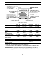
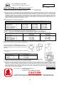
WOOD STOVE
MODELS
1000, 1600, 1600INS, 2100
OWNERS AND OPERATORS MANUAL
EF-183
TABLE OF CONTENTS
•
PLEASE READ AND SAVE INSTRUCTIONS
•
OPERATING INSTRUCTIONS
3
•
PEDESTAL INSTALLATION
7
•
BRICK INSTALLATION
SAFETY WARNING
2
•
MODEL 1000
8
•
MODEL 1600 INSERT
9
•
MODEL 2100
10
•
FREESTANDING INSTALLATION
11
•
MOBILE HOME INSTALLATION
12
•
FIREPLACE INSERT INSTALLATION
13
•
HOW IT WORKS
14
•
SPECIFICATIONS
15
•
DOOR INSTALLATION
16
•
OPTIONAL FAN INSTALLATION (WIRING DIAGRAM)
17
•
RATING LABEL COPY
18
•
PARTS AND ACCESSORIES
19
•
WARRANTY
20
•
EXPLODED VIEW
21
PLEASE READ AND SAVE INSTRUCTIONS
SAFETY WARNING
•
•
•
•
•
•
•
•
Please read this entire manual before you install and use your new heater. Failure to follow these
instructions may result in property damage, personal injury, and even death.
If this appliance is not properly installed, operated, and maintained a serious house fire could
result. Do not use any makeshift materials during installation.
Never place wood, paper, furniture, drapes or other combustible materials near the stove, or let
children or pets touch it when it is hot.
Operate only with the door and ash pan tightly closed and burn wood directly on the stove floor.
Do not operate if the door glass is broken or a gasket is missing or damaged. Do not alter the
combustion air control valves. Dangerous overfiring could occur which could ignite creosote in the
chimney or cause a house fire.
At least 12 inches2 (77.4 cm2) of fresh outside air should be admitted into the room or directly to
the stove through a 4” inches (10.16 cm) diameter pipe. It would be dangerous to operate the
stove with the combustion-air inlet closed.
Do not burn coal or charcoal, as there is danger of carbon monoxide being produced. Do not use
chemical fluids to start or re-fresh the fire. Do not burn garbage or flammable fluids such as
gasoline, grease, or naphtha or engine oil. Never let the stove become hot enough to get any part
red or glowing red.
Burning wet unseasoned wood could cause excessive creosote accumulation. When ignited it
could cause a chimney fire that could result in a serious house fire.
Do not use grates, andirons or any other methods to support or raise the fire up off the hearth of
the appliance.
2
OPERATING AND LIGHTING INSTRUCTIONS
FIRST START:
When first installed, the chimney, firebricks and steel are cold and it usually takes several hours on a fairly high
burn for them to become hot and dry enough for the stove to function well. The paint will smell a little for the first
time or two as it cures. You may wish to open a door or window to eliminate the smell.
DRAFT CONTROL:
Located on the front of the stove just below the ash sill is the Slider Air Damper. This damper will control the
amount of air to the fire. Pull this control all the way out when first starting the stove. Once the fire has been
established you may adjust this control to set the burn rate of the fire. If this damper is closed at first start up the
fire will burn very slowly and could soot the appliance.
FANS:
All models have been approved for operation with or without the optional fans supplied by the manufacturer. On
medium or high burns, using a fan will increase the heat transfer slightly. Route the power supply cord along the
floor behind the stove where it will remain cool.
DISPOSAL OF ASHES:
If you let the ashes accumulate two or three inches on the floor they tend to burn themselves up. Open the small
trap door located on the floor of the unit. Push the ashes that have accumulated into the hole were the ashes
would drop into the ash pan. Ensure that the trap door is closed properly before relighting the unit. When
necessary put the ashes in a metal container with a tightly fitting lid. Place the closed container on a noncombustible floor, well away from combustible materials. If the ashes are to be buried in soil or otherwise locally
dispersed, keep them in a closed container until all cinders have cooled. If your model has an ash pan, be sure to
latch the ash pan tightly when finished. Small amounts of cold wood ash can be used in the garden or compost.
REPLACING THE GLASS:
Never strike or slam the door, hit the glass or let burning wood rest against it. If the glass cracks when the fire is
burning, do not open the door until the fire is out and do not operate the stove again until the glass has been
replaced, preferably by your dealer. To remove the door, open and lift. To replace the glass, remove the steel
retaining clips and all loose glass. Replace only with Neoceram 5 mm glass 16.61” (422 mm) x 10.63” (270 mm)
and wrap the edges with 0.125” (3.2 mm) x 0.5” (13 mm) self-adhesive fiberglass gasket.
FIRE EXTINGUISHER AND SMOKE DETECTION:
All homes with a solid fuel burning stove should have at least one fire extinguisher in a central location known to
all in the household, and at least one smoke detection devise in the room containing the stove. If it sounds the
alarm, correct the cause but do not deactivate or relocate the smoke detection devise.
CREOSOTE - ITS FORMATION AND REMOVAL:
When wood is burned slowly, it may produce tar and other vapors that combined with moisture form creosote.
These vapors condense in the relatively cooler chimney flue of a slow burning fire, and if ignited, make an
extremely hot fire. So, the smoke pipe and chimney should be inspected bi-weekly during the heating season to
determine if a build-up has occurred. If creosote has accumulated it should be removed to reduce the risk of a
chimney fire.
CHIMNEY OR RUN AWAY FIRE:
1. Call local fire department (or dial 911)
2. Close the draft fully
3. Examine flue pipes, chimney, attic, and roof of the house, to see if any part has become hot enough to catch
fire. If necessary spray with fire extinguisher or water from the garden hose.
4. Do not operate the stove again until you are certain the chimney and its lining have not been damaged.
MAINTENANCE:
At the end of each heating season clean the chimney and the smoke pipe. If soot has accumulated above the top
baffle bricks, remove, clean, and then replace them. If the secondary air tube is badly eroded, replace it. Replace
worn door gaskets and broken bricks as needed. FAILURE TO INSPECT AND CLEAN YOUR CHIMNEY
SYSTEM REGULARLY CAN RESULT IN A CHIMNEY FIRE, WHICH COULD DAMAGE THE CHIMNEY OR
CAUSE A HOUSE FIRE.
3
Building Your Fire
Proper operation of your stove will help to ensure safe, efficient heating. Please take a few moments to review
these simple operating procedures.
1. Fuel Selection:
This stove is designed to burn natural wood only. Higher efficiencies and lower emissions generally result
when burning air-dried seasoned hardwoods, as compared to softwoods or to green or freshly cut hardwoods. DO
NOT BURN the following: treated wood, coal, garbage, solvents, colored papers, or trash. Burning these may
result in the release of toxic fumes and may poison or render the catalytic ineffective. Burning coal, cardboard, or
loose paper can produce soot, or large flakes of char or fly ash that can coat the combustor, causing smoke
spillage into the room, and rendering the combustor ineffective.
2. Building/Maintaining a Fire:
a) Open the primary air slide by pulling it all the way to the right.
b) Place a base of crumpled uncolored newspaper in the bottom of the stove. Lay pieces of kindling on top of
the newspaper and light it.
CAUTION: "Never use gasoline, gasoline-type lantern fuel, kerosene, charcoal lighter fluid, or similar
liquids to start or "freshen up" a fire in this heater. Keep all such liquids well away from heater while it
is in use.
c) As the kindling begins to burn, add several larger pieces of wood until the fire is burning well. At this point,
regular size logs may be added.
NOTE: Until the fire is burning well, leave the draft controls fully open.
d) Regulate the heat output of the stove by adjusting the draft controls to allow a larger fire and vice versa. A
short period of experimentation with the control settings will allow you to regulate the heat output to keep your
home comfortable.
Do not use a grate or elevate the fire. Build wood fire on the stove firebox hearth floor.
3. Refueling the Stove:
Use a long pair of gloves (barbecue gloves) when feeding the fire because these stoves burn at the front they are
clean and efficient, but they are also very hot and gloves are useful. Keep a small steel shovel and whisk nearby
for moving a log or lifting a fallen ember and for keeping the hearth clean.
a) Before attempting to add fuel to the stove, OPEN the damper control fully by pulling it all the way out. This
allows the chimney to carry away the additional smoke, which occurs when the door is open.
b) DO NOT OVERLOAD THE STOVE. Normally, three or four logs will provide heat for several hours. Never
operate this stove where portions glow red hot.
c) DO NOT OVERFIRE. If the heater or chimney connector glows, you are overfiring.
d) CAUTION: DO NOT PLACE FUEL WITHIN SPACE HEATER INSTALLATION CLEARANCES OR WITHIN
THE SPACE REQUIRED FOR CHARGING AND ASH REMOVAL.
4. For Maximum Efficiency:
When the stove is hot, load it fully to the top of the door opening, and burn at medium low settings. When the
fuel is mostly consumed, leaving a bed of red coals, repeat the process. Maximum heat for minimum fuel occurs
when the stovetop temperature is between 250°F (120°C) and 550°F (290°C). The most likely causes of dirty
glass are: not enough fuel to get the stove thoroughly hot, burning green or wet wood, closing the draft until there
is insufficient air for complete combustion, or a weak chimney draw. Indeed, the cleanness of the glass is a good
indicator of the stove operating efficiently.
4
Helpful Hints Worth Repeating
1. Helpful advice on the correct way to start your fire.
a) You will need small pieces of dry wood, called kindling, and paper. Use only newspaper or paper that has
not been coated or had other materials glued or applied to it. Never use coated (typically advertising flyers) or
coloured paper.
b) Always open the door of the wood stove slowly to prevent suction and drawing smoke into the room.
c) Crumple several pieces of paper and place them in the center of the firebox and directly onto the firebricks
of the wood stove. Never use a grate to elevate the fire.
d) Place small pieces of dry wood (kindling) over the paper in a “teepee” manner. This allows for good air
circulation, which is critical for good combustion.
e) Light the crumpled paper in 2 or 3 locations. Note: It is important to heat the air in the stovepipe for draft to
start.
f) Fully open the air controls of the wood stove and close the door until it is slightly open, allowing for much
needed air to be introduced into the firebox. Never leave the door fully open, as sparks from the kindling may
fly out of the stove, causing damage or injury. As the fire begins to burn the kindling, some additional kindling
may be needed to sustain the fire. DO NOT add more paper after the fire has started.
g) Once the kindling has started to burn, add some smaller pieces of seasoned, dry firewood. Note: Adding
large pieces at the early stages will only serve to smother the fire. Continue adding small pieces of seasoned
dry firewood, keeping the door slightly open until each piece starts to ignite. Remember to always open the
door slowly between placing wood into the fire.
h) Once the wood has started to ignite and the smoke has reduced, close the wood stove door fully. The
reduction of smoke is a good indication that the draft in the chimney has started and good combustion is now
possible. Larger pieces of seasoned, dry firewood can now be added when there is sufficient space in the
firebox. Adjust the air control setting to desired setting. Note: The lower the air control setting, the longer the
burn time of your firewood.
2. What type of wood is best to use as firewood?
Both hardwood and softwood burn well in this stove. Both woods contain about 8,000 BTUs per pound, but
hardwood is generally denser, will weigh more per cord, and burns a little slower and longer. Cutting firewood so
that it will fit horizontally, front to back, makes it easier loading and less likely for the fuel to roll on the glass.
Except for a cold start, there is no need to crisis-cross the logs. Ideal lengths would be about 12 “ for models
1000, 16.5” for model 1600, 21 “ for model 2100. Burn only dry, seasoned wood. It produces more heat and less
soot or creosote. Freshly cut wood has about 50% moisture. A ten-pound log contains 5 pounds of water. To
season firewood split and stack it so that air can get to all parts of the wood. Burn beach wood only if its salt
content has been washed away in a season of rain and then the wood dried. To prevent smoke spillage, when
refueling, open the door slowly.
3. What does dry, seasoned wood mean?
Wood that has been dried for a period of one year in a well-ventilated and sheltered area would be considered
dry, seasoned wood. Wood from slow-growing trees is generally considered better than wood from fast-growing
trees. To season firewood split and stack it so that air can get to all parts of the wood.
4. Will following the above-listed steps for starting a fire mean perfect results every time?
The quick answer is ‘ most of the time’. There are many variables that may affect your success when starting a
fire. Most of those variables and how to deal with them will be learned through experience. Your ability to start a
good fire will significantly increase with time and patience. Some of the reasons for poor stove performance will
be covered in the next section of these instructions.
5
5. Why can’t I get the fire lit?
Damp or wet wood and poor drafts are the main reasons for poor results in starting a fire. Always use dry,
seasoned wood for your fire. Even wood dried for two years will be difficult to ignite if it has become wet.
6. Is it normal for soot to cover the glass at the beginning of a fire?
Your stove has been built with an air-wash system that will help keep the glass clear when the firebox has
reached a good operating temperature and has a good draft. Normally a hot stove will keep the glass clean, but if
you must clean the glass, use a soft cloth with no abrasive and clean only when cold. Cold firebox temperature
and poor draft cause sooting of the glass. Once the firebox temperature and the draft increase, the soot will burn
off.
7. What is draft?
Draft is the ability of the chimney to exhaust or draw smoke produced during the normal combustion process. Too
much draft may cause excessive temperatures in the appliance and may damage the appliance*. Inadequate
draft may cause backpuffing or "plugging" of the chimney. There is a certain amount of draft that is required to
allow for your stove to function at its’ highest efficiency. A water column gauge can be used to reference this
amount.
8. What can cause a poor draft?
The most common factors for poor draft are:
a) Air supply
b) Environmental conditions
c) Cold chimney temperature
d) Poor chimney installation and maintenance
e) Atmospheric pressure
a) Air supply – Inside the home, normal household appliances such as clothes dryers and forced-air furnaces
compete for air, resulting in air starvation to the fire. This creates a condition in the house known as negative
pressure. When a house experiences negative pressure, the combustion gases can be drawn from the
chimney and into the house. This condition is commonly referred to as down drafting. Increased amounts of
insulation, vinyl windows, extra caulking in various places and door seals can all keep heat in but may also
make a home too airtight. An easy way to stop negative pressure in a home is to crack a window in the room
containing the stove.
b) Environmental Conditions - High trees, low-lying house location such as in a valley, tall buildings or
structures surrounding your house and windy conditions can cause poor draft or down drafting.
c) Cold Chimney Temperature - Avoid cold chimney temperatures by burning a hot fire for the first fifteen to
forty minutes, being careful not to over-fire the stove. If any part of the chimney or parts of the stove starts to
glow, you are over-firing the stove. Where possible, install a temperature gauge on the chimney so
temperature drops can be seen.
d) Chimney Installation and Maintenance - Avoid using too many elbows or long horizontal runs or height of
your chimney. If in doubt, contact a chimney expert and/or chimney manufacturer for help. Clean chimney,
rain caps and especially spark arrestor regularly, to prevent creosote build-up, which will significantly reduce
chimney draw and possibly a chimney fire.
9. Should I close or open the air control fully when shutting down the stove?
When shutting down the stove, fully open the air control. This allows the chimney temperatures to remain as high
as possible for as long as possible. Cold chimney temperatures create creosote.
Note: These instructions are intended as an aid and do not supercede any local, provincial or state
requirements. Check with officials or authorities having jurisdiction in your area.
6
PEDESTAL AND LEG INSTALLATION
Please read and understand these instructions before installing ash pan and leg option.
Failure to follow these instructions carefully could cause personal injury or property damage.
All screws are pre installed on the base of the unit.
PEDESTAL
• Remove the bricks from the unit before
starting.
• Loosen the two carriage bolts that secure
the unit to the pallet. Slide the pallet towards
the front to release carriage bolts from the
key holed slots in the unit. Place the unit on
the pallet on its back.
• Slide the pedestal assembly over the bolts
located on the base of the unit using the key
holed slots provided.
• Tighten all four bolts ensuring the pedestal
is properly aligned to the edges of the unit.
• Ensure that the gasket material is properly
sealed before continuing.
• Stand the unit on the pedestal and set the
unit in the location ready for installation.
• If fresh air supply is being supplied from the
bottom of the unit please install the cover
plate supplied to the rear of the pedestal
covering the 4” inch hole.
•
•
•
•
•
•
7
LEGS AND ASH PAN
Place the unit on the pallet on its
back.
Slide the ash pan assembly over the
bolts using the key holed slots
provided and tighten all four bolts.
Ensure that the gasket material is
properly sealed before continuing.
Carefully remove the cast iron legs
from the packaging and secure each
leg with two bolts provided.
Secure all four legs, push the leg
towards the center of the stove and
align the legs with the outer edges of
the firebox.
Stand the unit on the legs and set the
unit in the location ready for
installation
MODEL 1000 BRICK PLACEMENT:
COMPLETE THE STOVE AND SMOKE PIPE INSTALLATION BEFORE PLACING THESE BRICKS.
1. Place the bottom layers of the sides and back of the firebox.
2. Place the floor bricks. The spaces between the bricks will soon fill with ashes.
3. Finish the sides and back ready to accept the top, ceiling bricks.
4. On the right and left sides, leave the front top brick out and install this brick last. Start with a 3” wide brick first,
lift this brick up and rest the brick on the center baffle plate and the top of the side bricks, make sure that it is
slid all they way to the back of the stove. Place a full width brick next, and then place another full width brick on
the top so that all the joints are staggered. Complete both sides of the ceiling bricks in this manner.
5. Install the last two bricks in the right and left side, uppermost front corners.
6. Make sure that all bricks are secure before starting a fire in this unit.
REMOVE CEILING BRICKS AND CLEAN ABOVE THEM ONCE A
YEAR. REPLACE ANY BROKEN BRICKS
WHEN REPLACING BRICKS USE ONLY CLAYBURN TYPE FIRE BRICKS.
TOTAL BRICKS:
25- FULL SIZE BRICKS
4- PARTIAL BRICKS
(9” LONG X 4.5” WIDE X 1.25” THICK)
(22.86 CM LONG X 11.43 CM WIDE X 3.175 CM THICK)
(9” LONG X 3” WIDE X 1.25” THICK)
(22.86 CM LONG X 7.62 CM WIDE 3.175 CM THICK)
3- 1/2 BRICK FOR ASH DUMP (4.5 “ LONG X 4.5“ WIDE X 1.25” THICK)
(11.43 CM LONG X 11.43 CM WIDE X 3.175 CM THICK)
8
MODEL 1600 BRICK PLACEMENT:
COMPLETE THE STOVE AND SMOKE PIPE INSTALLATION BEFORE PLACING THESE BRICKS.
1. Place the bottom layers of the sides and back of the firebox.
2. Place the floor bricks. The spaces between the bricks will soon fill with ashes.
3. Finish the sides and back ready to accept the top, ceiling bricks.
4. On the right and left sides, leave the front top brick out and install this brick last. Start with a 3” wide brick first,
lift this brick up and rest the brick on the center baffle plate and the top of the side bricks, make sure that it is
slid all they way to the back of the stove. Place a full width brick next, and then place another full width brick on
the top so that all the joints are staggered. Complete both sides of the ceiling bricks in this manner.
5. Install the last two bricks in the right and left side, uppermost front corners.
6. Make sure that all bricks are secure before starting a fire in this unit.
REMOVE CEILING BRICKS AND CLEAN ABOVE THEM ONCE A
YEAR. REPLACE ANY BROKEN BRICKS
WHEN REPLACING BRICKS USE ONLY CLAYBURN TYPE FIRE BRICKS.
TOTAL BRICKS:
35- FULL SIZE BRICKS
4- PARTIAL BRICKS
(9” LONG X 4.5” WIDE X 1.25” THICK)
(22.86 CM LONG X 11.43 CM WIDE X 3.175 CM THICK)
(9” LONG X 3” WIDE X 1.25” THICK)
(22.86 CM LONG X 7.62 CM WIDE 3.175 CM THICK)
1- 1/2 BRICK FOR ASH DUMP (4.5 “ LONG X 4.5“ WIDE X 1.25” THICK)
(11.43 CM LONG X 11.43 CM WIDE X 3.175 CM THICK)
9
MODEL 2100 BRICK PLACEMENT:
COMPLETE THE STOVE AND SMOKE PIPE INSTALLATION BEFORE PLACING BRICKS.
1. Place the bottom layers of the sides and back of the firebox.
2. Place the floor bricks. The spaces between the bricks will soon fill with ashes.
3. Finish the sides and back ready to accept the top, ceiling bricks.
4. On the right and left sides, leave the front top brick out and install this brick last. Start with a 3” wide brick first,
lift this brick up and rest the brick on the center baffle plate and the top of the side bricks, make sure that it is
slid all they way to the back of the stove. Place a full width brick next, and then place another full width brick on
the top so that all the joints are staggered. Complete both sides of the ceiling bricks in this manner.
5. Install the last two bricks in the right and left side, uppermost front corners.
6. Make sure that all bricks are secure before starting a fire in this unit.
REMOVE CEILING BRICKS AND CLEAN ABOVE THEM ONCE A
YEAR. REPLACE ANY BROKEN BRICKS
WHEN REPLACING BRICKS USE ONLY CLAYBURN TYPE FIRE BRICKS.
TOTAL BRICKS:
39- FULL SIZE BRICKS
8- PARTIAL BRICKS
(9” LONG X 4.5” WIDE X 1.25” THICK)
(22.86 CM LONG X 11.43 CM WIDE X 3.175 CM THICK)
(9” LONG X 3” WIDE X 1.25” THICK)
(22.86 CM LONG X 7.62 CM WIDE 3.175 CM THICK)
3- 1/2 BRICK FOR ASH DUMP (4.5 “ LONG X 4.5“ WIDE X 1.25” THICK)
(11.43 CM LONG X 11.43 CM WIDE X 3.175 CM THICK)
10
FREESTANDING INSTALLATION:
CHIMNEY:
Vent the stove into a clean, lined, approved masonry
chimney in good condition, conforming to local building
codes or a listed 6” factory built chimney suitable for
use with solid fuels and conforming to, ULC-S629 in
CANADA or UL-103HT in the U.S.A.. Connect the stove
to this chimney with a short and straight 6” (150 mm),
25 gauge or heavier, single wall black or blued steel
smoke pipe. Connection to all masonry chimneys must
be a metal or masonry thimble cemented in place. All
smoke pipes must slope upwards, all connections must
be tight and secured with three sheet metal screws
equally spaced. The smoke pipe length should not
exceed 40% of the chimney height above the stove.
A non-combustible floor protector is required
under all freestanding units. The floor
protection must extend 18” (457 mm) in front of
the unit and 8” (203 mm) to each side. When
venting into a masonry chimney the floor
protector must be installed directly below the
chimney vent and 2” (50.8 mm) on either side
of the chimney vent.
DO NOT CONNECT THIS UNIT TO A CHIMNEY
FLUE SERVING ANOTHER APPLIANCE.
MAINTAIN THESE MINIMUM CLEARANCES TO UNSHIELDED COMBUSTIBLES*
DOUBLE WALL
PIPE**
DOUBLE WALL
PIPE**
MODEL 1000
MODEL 1600
MODEL 2100
MODEL 1000
MODEL 1600
A. SIDE TO UNIT
19 “ (485 MM)
20” (510 MM)
22” (560 MM)
14” (355 MM)
11” (280 MM)
B. REAR TO UNIT
10” (2556 MM)
12” (300 MM)
12” (300 MM)
6” (150 MM)
4” (101 MM)
C. CORNER TO UNIT
6” (150 MM)
6” (150 MM)
8” (200 MM)
2” (50 MM)
6” (150 MM)
D. SIDE TO COLLAR
28” (710 MM)
29” (735 MM)
31” (790 MM)
23’ (585 MM)
20” (508 MM)
E. REAR TO COLLAR
13” (330 MM)
16.5” (420 MM)
16.5” (420 MM)
9” ( 230 MM)
8.25” (210 MM)
F. CORNER TO COLLAR
16” (405 MM)
16.5” (420 MM)
19 “ (485 MM)
11.5” (290 MM)
15.5” (394 MM)
CAUTION: AN UN INSULATED SMOKE PIPE MUST NOT PASS THROUGH AN ATTIC, ROOF SPACE,
CLOSET OR SIMILAR CONCEALED SPACE, OR THROUGH A FLOOR, CEILING, WALL, OR PARTITION,
OR ANY COMBUSTIBLE CONSTRUCTION.
*ALL CLEARANCES CAN BE REDUCED WITH SHIELDING ACCEPTABLE TO THE LOCAL AUTHORITY.
**DOUBLE WALL: IN CANADA: ANY ULC-629 LISTED CHIMNEY SYSTEM WITH THE ACCOMPANYING
LISTED DOUBLE WALL VENT CONNECTOR.
IN U.S.A.: ANY HT-103 LISTED CHIMNEY SYSTEM WITH THE ACCOMPANYING
LISTED DOUBLE WALL VENT CONNECTOR.
11
OUTSIDE AIR:
A 4” (10.16 cm) fresh air adapter kit is available. This adapter can be installed either
on the back pedestal or through the floor under the pedestal.
Place the ¼” mesh screen between the fresh air adapter and the body of the
pedestal. (AS SHOWN)
NOTE: Fresh air connection to the unit must be a non combustible pipe.
(Example: 4” (10.16 cm) single wall aluminum flex pipe)
NOTE: REMOVE THE 4” KNOCK OUT ON THE REAR OF THE
PEDESTAL IF ROOM AIR IS TO BE USED FOR
COMBUSTION AIR
Pedestal
rear
ALCOVE INSTALLATION;
Model 1000 May be installed with double wall pipe in an alcove up to 4
ft. (1.2 m) deep and at least 7 ft. (2.13 m) high: sides 14” and rear 6”.
Model 1600 May be installed with double wall pipe in an alcove up to 30” (76 cm) deep and at least 70” (178 cm)
high and a minimum width of 48” (122 cm)
FLOOR PROTECTION:
If a stove is installed on a combustible floor, it must have a pedestal attached and be on a NON COMBUSTIBLE
hearth pad extending at least 8” (200 mm) to each side, and 18” (455 mm) to the front as indicated below.
TO INSTALL A LISTED, FACTORY BUILT CHIMNEY.
1. Set floor protector and stove in location in accordance with the clearances required
above (see previous page).
2. Mark the position for the ceiling hole by using a plumb bob.
3. Move this location, if necessary, to avoid floor joists, ceiling rafters while still maintaining
required clearances (see manufacturer’s label on page 15 or the clearances to
combustibles on page 8).
4. Mark the hole for the outside air kit.
5. Move the stove out of the way.
6. Cut a pilot hole in the ceiling.
7. Cut a hole for the ceiling penetration components and frame in the sides of the hole in
both the ceiling and roof. Check, and follow chimney manufacturer’s instructions for all
of these steps.
8. Install the support box and chimney through the roof. Install the slip section for the
chimney connector.
9. Slip the roof flashing over the chimney and secure to the roof, being careful to keep the
pipe centered in the opening. To meet the code, the chimney must extend above the
roof at least 3 FT. (91.44 cm), and 2 FT. (60.9 cm) above any area of the roof, within 10
FT. (304.8 cm) of the end of the chimney.
10. Be sure all pieces including outside rain cap, flange, collar and pipe are installed and then place the stove
back into position.
11. Install the smoke pipe with the lower (crimped) edge of the pipe inside the smoke collar. Any creosote formed
will then run back down into the stove. All connections must be tight and secured with three sheet metal
screws equally spaced.
12. Also install an outside air flex pipe to the stove.
12
MOBILE HOME INSTALLATION
SPECIAL REQUIREMENTS: Pedestal models 1000 and 1600 are approved for mobile homes. All freestanding
installation requirements on the preceding page plus the following must be met:
VENTING:
In Canada: Any ULC-629 listed chimney system with the accompanying double wall vent connector. In U.S.A.
Any HT-103 listed chimney system with the accompanying double wall vent connector. Do not connect a listed
chimney of one manufacture with a listed double wall connector from another manufacture. These connectors
must be installed in accordance with the manufacturer’s instructions. Use only specified components. The
chimney and pipe must extend at least 10-ft. (2.4m) above the stove and 3-ft. (.9 m) above the highest point of the
roof. (RECOMMENDED CHIMNEY HEIGHT 12’ FEET) Install a rain cap with spark arrestor at the top that will not
impede the smoke exhaust. The chimney must be supported at the ceiling or roof so that its weight will not sit on
the stove. Seal with silicone to maintain vapor barrier at the chimney and outside air penetrations. CAUTION:
THE STRUCTURAL INTEGRITY OF THE MOBILE HOME FLOOR, WALL, AND CEILING/ROOF MUST BE
MAINTAINED.
OUTSIDE AIR :
Connection from the stoves air intake to the outside
is mandatory, (MOBILE HOMES ONLY) either
through a hole in the wall not higher than the stoves
bottom, or through a hole in the floor beneath the
pedestal using the fresh air adapter provided. If the
air intake is through the floor, the hole in the pedestal
back must be closed with the sheet metal cover
provided. Avoid cutting any floor joists, wall studs,
electrical wiring or plumbing. Seal around the outside
air pipe with insulation to prevent drafts. Also install a
¼” mesh rodent or pest screen in the end of fresh air
pipe. Fresh air connection must be of a noncombustible material (example: 4” 10.16 cm flexible
aluminum single wall pipe.)
Fresh air could also be supplied from a vented
crawlspace
The pedestal must be firmly bolted to the floor using
¼” bolts. Be sure to replace any insulation or panels
removed when fastening the bottom nuts.
If room air starvation occurs because the air intake is
blocked with ice, leaves etc. Or because the stove
door was left open, or due to a strong exhaust fan
operating, dangerous fumes could be sucked into the
room.
IN SOME AREAS IT MAY BE REQUIRED TO ELECTRICALLY GROUND THE STOVE.
When this unit is installed in a Mobile Home it must be grounded to the steel chassis or connected to a grounding
rod.
Manufactured (Mobile) home installation must be in accordance with the Manufactured Home Construction and
Safety Standard, UL 307B, Title 24 CFR, Part 3280 and/or The Standard for Manufactured Home Installations,
ANSI A225.1/NFPA 501A
WARNING:
DO NOT INSTALL IN A MOBILE HOME SLEEPING ROOM.
13
MODEL 1600 INS FIREPLACE INSERT
Unless you are experienced, we recommend installation
by your dealer or a professional installer.
Install only in a masonry fireplace at least 25” (635 mm)
wide, 22” (560 mm) high and 14” (356 mm) deep with an
approved lined chimney at least 15 ft (4.6 m) high, both of
which have been constructed in accordance with the
building code. Be sure the fireplace and chimney are
clean and sound without any cracks or loose mortar. Do
not remove any bricks or mortar from the fireplace.
1. Remove any fireplace damper or fasten in a permanent
open position.
(IN CANADA)
2. The stove is vented with a 6” stainless steel liner that
goes directly to the top of the chimney and is covered with
a rain cap. The chimney top is sealed with a flashing or
steel plate that supports the weight of the chimney liner.
The installation must conform to the liners manufacturer’s
instructions.
This fireplace must be installed with a continuous liner of
6” diameter (CANADA ONLY) extending from the fireplace
insert to the top of the chimney. The chimney liner must
conform to the class 3 requirements of CAN/ULC-S635,
standard for lining systems for existing masonry or factory
built chimneys and vents, or CAN/ULC-S640, Standards
for lining systems for new masonry chimneys.
(IN U.S.A.)
The appliance when installed, must follow local building codes, in the absence of local building codes, with the
current NFPA 211 Standard for Chimneys, fireplaces, vents, and Solid Fuel Burning Appliances
Screw or Nail the metal plate provided form the manufacture to the inside of the fireplace.
METAL TAG: “THIS FIREPLACE HAS BEEN ALTERED TO ACCOMMODATE A FIREPLACE INSERT AND
SHOULD BE INSPECTED BY A QUALIFIED PERSON PRIOR TO THE RE-USE AS A
CONVENTIONAL FIREPLACE.”
REQUIRED CLEARANCES TO COMBUSTIBLES FROM INSERT:
Minimum clearances to an unshielded sidewall:
17” (430 mm)
Minimum clearances to an unshielded mantle:
28” (710 mm)
Minimum top facing clearance:
28” (710 mm)
Minimum side facing clearance:
1” (25 mm)
If there is a combustible floor in front of the masonry
fireplace, the fireplace insert must be 8” (205 mm) above
the combustible floor, and floor protection must be provided
18” (455 mm) in front of the fireplace insert and 8 “(205
mm) to each side of the unit.
14
HOW IT WORKS
SPECIFICATIONS:
WIDTH X DEPTH
HEIGHT ON PEDESTAL
HEIGHT OF BODY
FUEL CHAMBER
DEPTH X WIDTH X HEIGHT
CAPACITY
*APPROXIMATE HEATING
AREA
** EPA OUTPUT RATING
* DURATION ON LOW BURN
WEIGHT WITHOUT BRICKS
WEIGHT OF BRICKS
E.P.A. EMISSIONS
SURROUND PANELS
MODEL 1000
24 X 21”
(.61 X .53 M)
33 “ (.83 M)
22” (.56 M)
12.5 X 18 X 12”
(.3 X .46 X .3 M)
1.7 CU. FT.
3
(.048 M )
1000 SQ. FT.
2
(85 M )
11700 to 32700
BTU/Hr
5 TO 7 HOURS
311 LBS
(141 KG)
63.58 LBS
(28.9 KG)
4.1 G/HR
MODEL 1600
24 X 25.5”
(.61 X ..64 M)
33 “ (.83 M)
22” (.56 M)
17 X 18 X 12”
(.42 X .46 X .3 M)
2.3 CU. FT.
(.065 M 3)
1600 SQ. FT.
(150 M 2)
11500 to 33600
BTU/Hr
7 TO 9 HOURS
356 LBS
(161 KG)
83.38 LBS
(37.9 KG)
3.5 G/HR
MODEL 1600fpi
24 X 25.5”
(.61 X .64 M)
N/A
22” (.56 M)
17 X 18 X 12”
(.42 X .46 X .3 M)
2.3 CU. FT.
(.065 M 3)
1600 SQ. FT.
(150 M 2)
11500 to 33600
BTU/Hr
7 TO 9 HOURS
337 LBS
(152 KG)
83.38 LBS (37.9
KG)
3.5 G/HR
MODEL 2100
24 X 30”
(.61 X .76 M)
33 “ (.83 M)
22” (.56 M)
21.5X 18 X 12”
(.53 X .46 X .3 M)
3.1 CU. FT.
(.082 M 3)
2100 SQ. FT.
(200 M 2)
11800 to 34000
BTU/Hr
9 TO 11 HOURS
414 LBS
(187 KG)
103.18 LBS
(46.9 KG)
2.9 G/HR
40” X 28”
101 X 71 CM
46” X 33”
117 X 84 CM
(STANDARD SURROUND)
(OVERSIZE SURROUND)
*FIGURES WILL VARY CONSIDERABLY WITH FUEL AND CONDITIONS.
** E.P.A. OUTPUT IS CALCULATED FROM A LOAD OF FIR AVERAGED FROM START UNTIL ENTIRELY
CONSUMED. THE ACTUAL HEAT OUTPUT WITH REFUELING IS VERY MUCH GREATER.
CERTIFICATION: THESE STOVES HAVE BEEN TESTED AND LISTED by INTERTEK (ITS) (WH). TO
STANDARDS. CSA B366.2/ULC-S627, ULC-S628-M93, UL 1482-1994, MODELS 1000 AND
1600 FREESTANDING UNITS HAVE BEEN TESTED AND LISTED FOR USE IN MOBILE
HOMES.
15
DOOR INSTALLATION
Remove the door from the packaging. Inspect the door
assembly for damage. DO NOT USE DOOR IF GLASS IS
BROKEN.
Place the door assembly on the two hinge pins mounted
on the body of the unit. Open and close the door, applying
pressure down, to ensure the door assembly is properly
seated on the hinges.
NUT
CAST LATCH
WASHERS X 2
SPRING WASHER
FERAL
HANDLE
CLOSE THE DOOR
ASSEMBLY AND TURN
THE DOOR HANDLE
DOWNWARDS UNTIL
DOOR IS TIGHT
Thread slider damper spring handle onto slider
damper control.
16
OPTIONAL FAN INSTALLATION
The appliance when installed must be electrically connected and grounded in accordance with local codes or in
the absence of local codes, with the current CSA C22.1 CANADIAN ELECTRICAL CODE. Part 1, SAFETY
STANDARDS FOR ELECTRICAL INSTALLATIONS, or THE NATIONAL ELECTRICAL CODE ANSI / NFPA 70 in
the USA.
CAUTION
Label all wires
prior to
disconnection
when servicing
controls. Wiring
errors can cause
improper and
dangerous
operation. Verify
proper operation
after servicing.
1) Remove the fan assembly from the box and inspect
for any damage to the assembly.
2) Remove the metal knock out on the rear of the
appliance.
3) Install two screws into the top two holes. Place the
blower assembly over these two screws and tighten.
Install the two bottom screws and tighten.
4) Plug the fan assembly in and check for proper
operation.
DO NOT cut or remove the grounding prong from the plug. Also do not route the power cord beneath the heater.
WARNING: ELECTRICAL GROUNDING INSTRUCTIONS.
This appliance is equipped with a three-prong (grounding) plug for your protection against shock hazard and
should be plugged into a properly grounded three-prong receptacle.
WIRING DIAGRAM
This is a basic wiring diagram for the option fan
installation. Models 1000, 1600, 2100
freestanding units only.
1) Plug the fan assembly into a three prong
(grounded) receptacle.
2) Turn the fan controller to the desired setting.
3) Once the unit has reached operating
temperature, the fan temperature sensor will
turn the fan on automatically.
4) When the unit cools down the fan
temperature sensor will shut the fan off
automatically.
17
DO NOT REMOVE THIS LABEL
WH-
LISTED SOLID FUEL SPACE HEATER SERIAL NO.
MODEL:
1000
1600
2100
1600 INS
MODEL 1000 SUITABLE FOR USE IN MOBILE HOMES.
CERTIFIED FOR CANADA AND THE U.S.A.
TESTED TO CSA B366.2/ULC-S627, ULC-S628-M93, UL-1482-1994
REPORT NO. J99011443-231
REPORT NO. 6385
INSTALL AND USE ONLY IN ACCORDANCE WITH THE MANUFACTURERS INSTALLATION AND OPERATING INSTRUCTIONS. CONTACT LOCAL
BUILDING OR FIRE OFFICIALS ABOUT RESTRICTIONS AND INSTALLATION INSPECTION IN YOUR AREA. USE 6 IN. / 150 MM DIAMETER
MINIMUM 24 MSG BLACK OR 25 MSG BLUED STEEL CONNECTOR LISTED FACTORY-BUILT CHIMNEY SUITABLE FOR USE WITH SOLID FUELS
OR MASONRY CHIMNEY. SEE LOCAL BUILDING CODE AND MANUFACTURER’S INSTRUCTIONS FOR PRECAUTIONS REQUIRED FOR PASSING
A CHIMNEY THROUGH A COMBUSTIBLE WALL OR CEILING. DO NOT PASS CHIMNEY CONNECTOR THROUGH A COMBUSTIBLE WALL OR
CEILING. MINIMUM CLEARANCES FROM HORIZONTAL CONNECTOR AND CEILING (18 IN./ 455 MM) DO NOT CONNECT THIS UNIT TO A
CHIMNEY FLUE SERVICING ANOTHER APPLIANCE U.S.A. ONLY.
MINIMUM CLEARANCES TO COMBUSTIBLE MATERIALS
RESIDENTIAL INSTALLATIONS USING SINGLE WALL CONNECTOR. WITH ANY ULC-S629 LISTED CHIMNEY IN CANADA , AND
ANY UL 103 HT LISTED CHIMNEY SYSTEMS IN THE U.S.A.
MODEL :1000
MODEL: 1600
MODEL: 2100
22 IN. / 560 MM
20 IN. / 510 MM
19 IN. / 485 MM
SIDE WALL TO UNIT
A
12 IN. / 305 MM
12 IN. / 305 MM
10 IN. / 255 MM
BACK WALL TO UNIT
B
8 IN. / 205 MM
6 IN. / 150 MM
6 IN. / 150 MM
CORNER TO UNIT
C
31 IN. / 790 MM
29 IN. / 735 MM
28 IN. / 710 MM
SIDE WALL TO CONNECTOR
D
16.5 IN. / 420 MM
16.5 IN. / 420 MM
13 IN. / 330 MM
BACK WALL TO CONNECTOR E
19 IN. / 485 MM
16.5 IN. / /420 MM
16 IN. / 405 MM
CORNER TO CONNECTOR
F
COMPONENTS REQUIRED FOR MOBILE HOME INSTALLATIONS: MODELS 1000 AND 1600
IN CANADA: ANY ULC-629 LISTED CHIMNEY SYSTEM WITH THE ACCOMPANYING DOUBLE WALL VENT CONNECTOR
IN U.S.A.:
ANY HT-103 LISTED CHIMNEY SYSTEM WITH THE ACCOMPANYING DOUBLE WALL VENT CONNECTOR
SPECIFIED CLEARANCES APPLY AND UNITS MAY BE INSTALLED IN CONVENTIONAL HOMES IF SPECIFIED CONNECTORS ARE USED.
MODEL 1000
MODEL 1600
11 IN. / 280 MM
14 IN./ 355 MM
SIDE WALL TO UNIT
A
4 IN. / 101 MM
6 IN. / 150 MM
BACK WALL TO UNIT
B
6 IN. / 153 MM
2 IN. / 50 MM
CORNER TO UNIT
C
20 IN. / 508 MM
23 IN. / 585 MM
SIDE WALL TO CONNECTOR
D
8.25 IN. / 210 MM
9 IN. / 230 MM
BACK WALL TO CONNECTOR
E
15.5 IN. / 394 MM
11.5 IN. / 290 MM
CORNER TO CONNECTOR
F
MODEL 1000 MAY BE INSTALLED IN AN ALCOVE: ALCOVE DEPTH, 4 FT. /1.22 M, HEIGHT 7 FT. 2.13 M
MODEL 1600 MAY BE INSTALLED IN AN ALCOVE: ALCOVE DEPTH 30” (76 CM) HEIGHT 70”(178 CM) WIDTH 48” (122 CM)
ROOM HEATER, SOLID FUEL TYPE, SUITABLE FOR MOBILE HOMES
If a stove is installed on a combustible floor, it must have a
pedestal attached and be on a NON COMBUSTIBLE hearth pad
extending at least 8” (200 mm) to each side, and 18” (455 mm)
to the front
MODEL 1600 INS MAY BE INSTALLED AS AN INSERT IN A MASONRY
FIREPLACE.
MINIMUM CLEARANCES TO COMBUSTIBLE MATERIALS (MEASURE TO UNIT)
MODEL 1600 INS
17 IN. / 430 MM
ADJACENT SIDE WALL A
28 IN. / 710 MM
MANTLE
B
28 IN. / 710 MM
TOP FACING
C
1 IN. / 25 MM
SIDE FACING
D
HEARTH EXTENSION MUST BE RAISED (F) 8 IN. / 205 MM ABOVE A SURROUNDING COMBUSTIBLE FLOOR.
COMBUSTIBLE FLOOR MUST BE PROTECTED BY A NON-COMBUSTIBLE MATERIAL EXTENDING (E) 18 IN.
455 MM TO THE FRONT OF THE UNIT AND (F) 8 IN. / 205 MM TO THE SIDES
OPERATE ONLY WITH THE DOOR AND ASH PAN CLOSED. ONLY OPEN DOOR TO FEED FIRE. FOR USE WITH SOLID WOOD FUELS ONLY. DO NOT
USE GRATE OR ELEVATE-FIRE BUILD WOOD FIRE DIRECTLY ON HEARTH. DO NOT OVERFIRE, DO NOT OBSTRUCT COMBUSTION AIR
OPENINGS.. IF HEATER OR CHIMNEY CONNECTOR GLOWS, YOU ARE OVERFIRING. INSPECT AND CLEAN CHIMNEY FREQUENTLY-UNDER
CERTAIN CONDITIONS OF USE, CREOSOTE BUILDUP MAY OCCUR RAPIDLY. KEEP FURNISHING AND OTHER COMBUSTIBLES WELL AWAY
FROM HEATER. REPLACE GLASS ONLY WITH CERAMIC GLASS. OPTIONAL COMPONENTS: FAN, ELECTRICAL RATING 115V, 60 Hz 1 AMP.
ROUTE CORD AWAY FROM HEATER (EFW-261).
MANUFACTURED BY: SHERWOOD INDUSTRIES LTD.
6782 OLDFIELD RD.
VICTORIA B.C V8M-2A3MADE
IN CANADA
CAUTION
HOT WHILE IN OPERATION. DO NOT TOUCH. KEEP CHILDREN, CLOTHING AND FURNITURE AWAY.
CONTACT MAY CAUSE SKIN BURN. READ NAMEPLATE
18
AND INSTRUCTIONS.
PARTS AND ACCESSIORIES
PLEASE CONTACT YOUR LOCAL ENVIRO DEALER WHEN REPLACEMENT PARTS ARE REQUIRED.
10-000
10-001
10-006
10-007
50-957
50-958
50-959
EC-042
EC-069
EF-045
EF-163
EF-164
EF-165
EF-166
EF-168
EF-169A
EF-169B
EF-169C
EF-170
EF-171
EF-173
EF-174
EF-177
EF-178
EF-182
EF-183
EF-186
EF-191
EF-197
EF-198
EFW-250
EFW-251
EFW-252
EFW-253
EFW-254
EFW-255
EFW 256
EFW-257
EFW-258
EFW-259
EFW-260
EFW-261
EFW-262
EFW-263
EFW-265
EFW-267
EFW-269
GLASS WITH GASKET
DOOR HANDLE ASSEMBLY (ROD, CAST LATCH, BRASS SPRING)
DOOR SPRING HANDLE - BRASS
DOOR SPRING HANDLE - NICKEL
SLIDER DAMPER – POST MAR1/01 (1000)
SLIDER DAMPER – POST MAR2/01 (1600)
SLIDER DAMPER – POST APR7/01 (2100)
POWER CORD
CONVECTION BLOWER – 115V
FAN CONTROLLER WITH KNOB - 115V
WOODSTOVE DOOR SKIN - PAINTED
WOODSTOVE DOOR SKIN - GOLD
1600 FPI PANEL SET (REGULAR)
1600 FPI PANEL SET (OVERSIZE)
DOOR GASKET
WOODSTOVE BRICK – 3” x 9”
WOODSTOVE BRICK – 4½” x 9”
WOODSTOVE BRICK – 4½” x 4½”
INNER DOOR (B) WITH GLASS AND GASKET
SECONDARY AIR TUBE
AIR SHUTTER CONTROL, SLIDER DAMPER – PRE MAR1/01 (1000)
AIR SHUTTER CONTROL, SLIDER DAMPER – PRE MAR2/01 (1600, 2100)
ASH PAN GASKET
ASH PAN LATCH
REAR SECONDARY AIR CHAMBER (2100)
OWNER’S MANUAL
FRESH AIR KIT
DAMPER HANDLE SPRING - BRASS
FREESTANDING ASH DRAWER (1000)
FREESTANDING ASH DRAWER (1600, 2100)
SET OF 4 LEGS W / ASH PAN (1000) - PAINTED
SET OF 4 LEGS W / ASH PAN (1000) - GOLD
SET OF 4 LEGS W / ASH PAN (1000) - NICKEL
ONE LEG - PAINTED
ONE LEG - GOLD
ONE LEG - NICKEL
FREESTANDING PEDESTAL (1000)
FREESTANDING PEDESTAL (1600, 2100)
CAST IRON DOOR WITH GLASS PAINTED
CAST IRON DOOR WITH GLASS GOLD
CAST IRON DOOR WITH GLASS NICKEL
FREESTANDING FAN KIT (1000, 1600, 2100)
REGULAR PANEL SET
OVERSIZE PANEL SET
SET OF 4 LEGS WITH ASH PAN (1600, 2100) - PAINTED
SET OF 4 LEGS WITH ASH PAN (1600, 2100) - GOLD
SET OF 4 LEGS WITH ASH PAN (1600, 2100) - NICKEL
19
WARRANTY
Because of our high standards Sherwood Industries Ltd. can offer a *Lifetime Warranty on all it’s wood products.
Covered under this warranty are Cabinet Sides, Tops, Pedestals, Surround Panels, Removable Air Channel, and
Chassis. These steel components are covered against manufacture’s defects for 1 year on parts and labor and for
parts only for the next 4 years. Please refer to the warranty agreement for specific details on the coverage of your
*Lifetime Warranty.
Sherwood Industries Ltd. offers an unlimited lifetime warranty for the secondary air tube (channel) for parts only
and labor for the first year.
Sherwood Industries Ltd. does not offer warranty on the following items:
Door and Ash Pan gasketing.
Firebricks.
(A) The following exclusions apply:
GOLD PLATING- Damage caused by scratching, marring, fingerprints, abrasive cleaners, overfiring and
discoloration with age.
GLASS- The use of harsh or abrasive cleaners, striking the glass or surface contaminates.
All claims under this warranty are to be made in writing by your dealer:
WHEN FILING A WARRANTY CLAIM PLEASE COMPLETE THE FOLLOWING
INFORMATION ON AN OFFICIAL WARRANTY CLAIM FORM:
To the Dealer
• Name, address and telephone number of purchaser and date of purchase.
• Date of installation. Name of installer and dealer. Serial number of the appliance. Nature of complaint, defect
or malfunction. Description and part # of any parts replaced.
To the Distributor
• Sign and verify that the work and information is correct.
This warranty covers defects in materials and workmanship only if the product has been installed according to the
manual’s instructions. If the product is damaged or broken as a result of misuse or mishandling, the warranty
does not apply. The warranty does not cover removal and re-installation costs.
Sherwood Industries Ltd. reserves the right to repair or to replace the defective product. The consumer pays for
the shipping costs. All warranties by the manufacture are set forth herein and no claim shall be made against the
manufacturer on any oral warranty or representation.
Sherwood Industries Ltd. and its employees or representatives will not assume any damages, either directly or
indirectly caused by improper usage, operation, installation, servicing or maintenance of this appliance.
Sherwood Industries Ltd. reserves the right to make changes without notice. Please complete and mail the
warranty registration card and have the installer fill in the installation data sheet in the back of the manual for
warranty and future reference.
SHERWOOD INDUSTRIES LTD.
6782 OLDFIELD ROAD
SAANICHTON, BRITISH COLUMBIA
V8M-2A3
January 27, 2004
20
ASH DUMP
COVER PLATE
FAN CONTROLLER 115V
EF-045
SECONDARY
AIR TUBE
EF-171
EF-196
CONVECTION
BL0WER – 115V
SET OF FOUR (4) LEGS with ASH PAN
EC-069
FREESTANDINGFAN KIT
120° TEMPERATURE
SENSOR
EFW 261
EC-040
FLAT TOP
CABINET SIDES
EF 1000:
PAINTED - EFW 250
GOLD - EFW 251
NICKEL - EFW 252
EF 1600 & 2100
PAINTED - EFW-265
GOLD - EFW-267
NICKEL - EFW-269
STEP TOP
CABINET SIDES
ASH PAN
LATCH
EF-178
SLIDER DAMPER
BRICKS
1000 50-957
1600 50-958
2100 50-959
3” X 9”
EF-169A
4½” X 9” EF-169B
4½” X 4½” EF-169C
SLIDER
DAMPER
SPRING
HANDLE
FRESH AIR KIT
EF-186
GLASS
with TAPE
10-000
EF-191
FREESTANDING
PEDESTAL
ASH PAN
LATCH
1000
EFW-256
1600, 2100 EFW-257
EF-178
WOOD STOVE -COMPONENTS
21
DOOR
HANDLE
ASSEMBLY
10-001
CAST DOOR
W/ GLASS
PAINTED
EFW-258
GOLD
EFW-259
NICKEL
EFW-260
SPRING
HANDLE
BRASS
10-006
NICKEL
10-007