1
US007099934B1
(12)
United States Patent
(10) Patent N0.:
US 7,099,934 B1
(45) Date of Patent:
Aug. 29, 2006
Ewing et a].
(54)
(76)
NETWORK-CONNECTING POWER
4,442,319 A
MANAGER FOR REMOTE APPLIANCES
4,495,568 A
1/1985 Gilbert et a1.
4,611,289 A
9/1986 Coppola
Inventors; Carrel W, Ewing; 285 Deer CL; Incline
4,647,721 A *
Village; NV (Us) 89451; Andrew J_
Cleveland, 5419 Greenview Ct., Reno,
NV (Us) 89502; Brian P- Auclair;
4540 Great Falls Loop, Reno, NV (US)
4,701,946
4,709,318
4,780,714
4,937,561
89511
A
A
A
A
5,164,609 A *
5,198,806 A
(*)
Notice:
Subject to any disclaimer, the term of this
patent is extended or adjusted under 35
USC‘ 1540’) by 711 days‘
(21) APP1- NO-I 09/732,557
Feed:
(63)
Related US Application Data
Continuation-in-part of application No. 09/375,471,
?led on Aug. 16, 1999, now Pat. No. 6,711,613,
3/1987 Busam et a1. ........ .. 379/102.04
10/1987
11/1987
10/1988
6/1990
Oliva et a1.
Gephart et a1~
Moustakas et a1.
Sasakl et a1‘
11/1992
Poppe et a1. .............. .. 307/147
3/1993 Lord
(Continued)
FOREIGN PATENT DOCUMENTS
WO
(22)
4/ 1984 Treidl
PCT/US91/08543
Dec‘ 8’ 2000
5/1993
OTHER PUBLICATIONS
which is a continuation-in-part of application No.
08/685,436, ?led on Jul. 23, 1996, now Pat. No.
5,949,974~
American Power Conversion, “Call-UPS”, 1991, #996-0070, AFC,
West Kmgston’ RI 02892 USA‘
(Continued)
_
_
Primary Exemmerile?crey PWu
Assistant ExamineriAshok Patel
(74) Attorney, Agent, or FirmiKlarquist Sparkman, LLP
(51)
Int. Cl.
G06F 15/173
(52)
US. Cl. .................... .. 709/223; 361/601; 361/622;
(58)
(2006.01)
(57)
ABSTRACT
713/340; 439/652; 337/186; 307/11; 307/18;
Anetwork comprises a power manager with a network agent
307/31; 307/32; 307/39; 307/37; 307/43;
307/ 149; 307/150
in communication over a network with an network manager.
The power manager is connected to control several intelli
Field of Classi?cation Search ................ .. 307/34,
gent PeWer modules eaeh able to independently eentrel the
307/35; 36; 37; 3g; 32; 43; 149; 150; 361/601;
power on/oiT status of several network appliances. Power-on
361/622; 713/340; 439/652; 337/186; 11;
337/18; 31
See application ?le for Complete Search history
and load sensors within each intelligent power module are
able to report the power status of each network appliance to
the network manager with variables in response to com
_
(56)
References Clted
US. PATENT DOCUMENTS
4,051,326
4,101,878
4,206,444
4,356,545
A
A
A
A
9/1977
7/1978
6/1980
10/1982
Badagnani et 31.
Shimizu et a1.
Ferlan
West
mands. Each intelligent power module is equipped with an
output that is connected to cause an interrupt signal to the
network appliance being controlled. The network manager is
able to test which network appliance is actually responding
before any cycling of the power to the corresponding
appliance is tried.
7 Claims, 3 Drawing Sheets
"202
200
US 7,099,934 B1
Page 2
US. PATENT DOCUMENTS
American Power Conversion, “PowerNet”, 1998, #996-0325D,
APC, West Kingston, RI 02892 USA.
5,319,571 A
6/1994 Langer et al.
5,359,540 A *
10/1994
Ortiz ........................ .. 700/295
5,374,922 A
12/1994 Ebersohl
5,381,554 A *
1/1995
Langer et al.
5,410,713 A
5,412,645 A
4/1995 White et al.
5/1995 Younkin et al.
B. Ewing and J. Mallory, “Power-ON/OFF-Product Information”,
1990, Server Technology, Inc., Reno, Nevada.
Raphael Needleman, “Power-ON/OFF Lets You Turn on Remote
.............. .. 714/14
Gilbert ...................... .. 307/38
PCs by Phone”, Feb. 1991, Info World Impression, V. 13, Issue 5.
Server Technology, Inc., “Any-To-Any Matrix Communications
Switch”, 1996, Server Technology, Inc. Reno, Nevada.
Server Technology, Inc., “Sentry Ambassador”, 1996, Server Tech
nology, Inc. Reno, Nevada.
Server Technology, Inc., “LAN WAN, Enterprise, Internet Access
5,436,510 A *
7/1995
5,481,730 A
5,485,576 A
5,495,607 A
1/1996 Brown et al.
1/1996 Fee et al.
2/1996 Pisello et al.
5,506,573 A
4/1996 Ewing et al.
Equipment”, 1996, Server Technology, Inc., Reno, Nevada.
Server Technology, Inc., “SENTRYRACK”, 1996, Server Technol
5,506,790 A *
4/1996
ogy, Inc., Reno, Nevada.
Nguyen .................... .. 700/286
5,537,462 A
5,561,769 A
7/1996 Utter et al.
10/1996 Kumar et al.
5,579,201 A *
11/1996
5,585,678 A
5,596,628 A
12/1996 Dijk et al.
1/1997 Klein
5,652,893 A *
5,687,079 A *
7/1997
11/1997
5,717,934
5,721,934
5,761,084
5,781,434
A
A
A
A
5,835,700 A *
2/1998
2/1998
6/1998
7/1998
11/1998
Karageozian ............. .. 361/119
Ben-Meir et al. ......... .. 713/310
Bauer et al. ................ .. 700/70
Pitt et al.
Scheurich
Edwards
Tobita et al.
Carbonneau et al. ....... .. 714/44
5,862,391 A
6,029,092 A
1/1999 Salas et al.
2/2000 Stein
6,046,513 A *
4/2000
6,408,395
6,496,103
6,507,273
6,519,509
B1
B1
B1
B1
6,715,088 B1
2002/0007463 A1*
2003/0200473 A1*
6/2002
12/2002
1/2003
2/2003
Server Technology, Inc. “SENTRY Communications and User
Interface”, 1996, Server Technology, Inc., Reno, Nevada.
Server Technology, Inc., “SENTRYSHELF”, 1996, Server Tech
nology, Inc., Reno, Nevada.
Server Technology, Inc., “SENTRY Power Modules”, 1996, Server
Technology, Inc., Reno, Nevada.
Server Technology, Inc., “SENTRY ShutDown Remote Power
Manager”, 1997, Server Technology, Inc., Reno, Nevada.
Server Technology, Inc., “SENTRY Administrator R-450 Remote
Power Manager”, 1999, Server Technology, Inc., Reno, Nevada.
Server Technology, Inc., “How Do You ReBoot Remote Equip
ment?”, 1999, Server Technology, Inc., Reno, Nevada.
Jouper et al. ............... .. 307/31
Server Technology, Inc., “SENTRY R-2000 Remote Power Man
Sugahara et al.
Weiss et al.
Chang et al.
Nierlich et al.
ager”, 1999, Server Technology, Inc., Reno, Nevada.
Server Technology, Inc., “MasterSwitcha”, 1996, Server Technol
3/2004 Togawa
1/2002
10/2003
Server Technology, Inc., “SENTRYINTERNATIONAL”, 1996,
Server Technology, Inc., Reno, Nevada.
Fung ........................ .. 713/320
Fung ........................ .. 713/320
OTHER PUBLICATIONS
American Power Conversion, “Measure-UPS”, Mar. 1993, #996
0127, APC, West Kingston, RI 02892 USA.
American Power Conversion,“Introducing the UPS to build your
business on . . . ”, Oct. 1993, #996-0207-A, APC, West Kingston,
RI 02892 USA.
American Power Conversion, “Application Note #A2”, Oct. 1993,
APC, West Kingston, RI 02892 USA.
American Power Conversion, “Application Note #A6”, Oct. 1993,
APC, West Kingston, RI 02892 USA.
American Power Conversion, “Internetworking Power Protection”,
Jan. 1994, # 996-0295, APC, West Kingston, RI 02892 USA.
American Power Conversion, “PowerNeta SNMP Adapter”, Jan.
1994, #996-0126, APC, West Kingston, RI 02892 USA.
American Power Conversion, “Solutions ’94”, Feb. 1994, #996
0131, APC, West Kingston, RI 02892 USA.
American Power Conversion, “APC NetShelter”, 1995, #996-0643
A, APC, West Kingston, RI 02892 USA.
American Power Conversion, “PowerNet”, Sep. 1995, #996-0325
b, APC, West Kingston, RI 02892 USA.
American Power Conversion, “APC Smart-UPS RM”, 1996, #996
0618-B, APC, West Kingston, RI 02892 USA.
American Power Conversion, “APC Smart-UPS XL”, 1996, #996
0630-B, APC, West Kingston, RI 02892 USA.
American Power Conversion, “Smart-UPS”, 1996, #996-0386-E,
APC, West Kingston, RI 02892 USA.
American Power Conversion, “PowerChute plus”, 1996, #996
0041-C, APC, West Kingston, RI 02892 USA.
American Power Conversion, “Internetworking Power Protection”,
1996, #996-0295-B, APC, West Kingston, RI 02892 USA.
American Power Conversion, “UPS Accessories”, 1996, #996
0411-C, APC, West Kingston, RI 02892 USA.
American Power Conversion, “Application Notes”, Oct. 1996,
#996-0495-C, APC, West Kingston, RI 02892 USA.
ogy, Inc., Reno, Nevada.
W. Richard Stevens. “TCP/IP Illustrated, vol. liThe Protocols”,
pp. 359-361, 1994.
Michael Slater. “Microprocessor-Based DesigniA Comprehensive
Guide to Hardware Design”, pp. 19-24, 1989.
Peter Drake. “Using SNMP to Manage Networks”, pp. 2/1-2/4,
1991.
Novak, T. “Remote Management of Individual Power Supplies”,
netman.cit.buffalo.edu/CDN-M, p. 1, May 10, 1995.
Uninteruptable Power Source FAQ, v. 1.0, pp. 1-10, Feb. 10, 1994.
Davison, M., et al. UPS Management Information Base, Internet
Draft, IETF, pp. 1-28, May 13, 1992.
Sentry Ambassador Remote Power Manager © 1996.
Sentry R-2000 Remote Power Manager © 2001.
Sentry 110/230 VAC Product Family © 2000.
Sentry Power Manager*48 VDC Product Family © 2000.
Distributed Power Module Product List, Sep. 23, 2002.
Sentry Power Modules © 1999.
Sentry Power Tower Products © 2001/2002.
Sentry Expanded Function Power Tower (PTEF) © 2001/2002.
Sentry Serial Power Tower (PTSS) © 2001/2002.
Sentry Power Tower Power Distribution © 2001/2002.
Sentry Commander R-400 Remote Power Mgr. © 2001/2002.
Sentry Commander R-400 Remote Pwr. Mgr. Datasheet © 1999.
Sentry Administrator R-450 © 2001/2002.
Sentry Administrator R-450 Remote Pwr. Mgr. © 1998.
Sentry Power On/Off, Installation and Operations Manual, © 1991.
Sentry Remote Power Manager brochure © 1991.
Power-On product wrapper © 1991.
Remote Power-On product wrapper © 1991.
Intelligent Power Module © 1991.
Local and Remote Power-On/Off Alternatives © 1991.
NEW BOX Speci?cation, dated Mar. 6, 1991.
RPM-15 Power Module Speci?cation, Mar. 18, 1991.
Sentry Remote Power Manager, Operational Instructions, Sep. 24,
1992.
“Keeping Up With . . . ”, INTERNET TELEPHONY, Mar. 2000, pp.
84-87.
“Rebooting Across the Net”, PC Magazine, May 5, 1998.
“Server Technology Sentry R-2000”, PC Magazine, May 5, 1998.
“APC MasterSwitch”, PC Magazine, May 5, 1998.
US 7,099,934 B1
Page 3
American Power Conversion, “Smart-UPS”, 1996, #996-0386-E
APC, West Kingston, RI 02892USA.
American Power Conversion, “PowerChute plus”, 1996, #996
004l-C, APC, West Kingston, RI 02892USA.
American Power Conversion, “Internetworking Power Protection”,
1996, #996-0295-B, APC, West Kingston, RI 02892USA.
American Power Conversion, “UPS Accessories”, 1996, #996
04ll-C, APC, West Kingston, RI 02892USA.
American Power Conversion, “Application Notes”, Oct. 1996,
#996-0495-C APC, West Kingston, RI 02892USA.
American Power Conversion, “PowerNetEl”, 1996, #996-0325D,
APC, West Kingston, RI 02892USA.
B. Ewing and J. Mallory, “Power-ON/OFF-Product Infomation”,
1990, Server Technology, Inc., Reno. Nevada.
Raphael Needleman, “Power-ON/OFF Lets You Turn on Remote
PCs by Phone”, Feb. 1991, Info World Impressions, V. 13, Issue 5.
Server Technology, Inc., “Any-To-Any Matrix Communications
Switch”, 1996, Server Technology, Inc., Reno, Nevada.
Server Technology, Inc., “Sentry Ambassador”, 1996, Server Tech
nology, Inc., Reno, Nevada.
Server Technology, Inc., “LAN, WAN, Enterprise, Internet Access
Equipment”, 1996, Server Technology, Inc., Reno, Nevada.
Server Technology, Inc., “SENTRYRACK”, 1996, Server Technol
ogy, Inc., Reno, Nevada.
Server Technology, Inc., “SENTRYINTERNATIONAL”, 1996,
Server Technology, Inc., Reno, Nevada.
Server Technology, Inc., “SENTRY Communications and User
Interface”, 1996, Server Technology, Inc., Reno, Nevada.
Server Technology, Inc., “SENTRYSHELF”, 1996, Server Tech
nology, Inc., Reno, Nevada.
Server Technology, Inc., “SENTRY Power Modules”, 1996, Server
Technology, Inc., Reno, Nevada.
Server Technology, Inc., “SENTRY ShutDown Remote Power
Manager”, 1997, Server Technology, Inc., Reno, Nevada.
Server Technology, Inc., “SENTRY Administrator R-450 Remote
Power Manager”, 1999, Server Technology, Inc., Reno, Nevada.
Server Technology, Inc., “How Do You ReBoot Remote Equip
ment?”, 1999, Server Technology, Inc., Reno, Nevada.
Server Technology, Inc., “SENTRY R-ZOOO Remote Power Man
ager”, 1999, Server Technology, Inc., Reno, Nevada.
Server Technology, Inc., “MasterSwitch”, 1996, Server Technology,
Inc., Reno, Nevada.
Server Technology, Inc., “Sentry Power Tower”, 2000, Server
Technology, Inc., Reno, Nevada.
American Power Conversion, “MasterSwitch plus”, Dec. 6, 2000,
APC, West Kingston, RI 02892USA.
American Power Conversion, “Built-in Serial UPS Support In
Windows 2000 Developd by APC”, Dec. 6, 2000, APC, West
Kingston, RI 02892USA.
Western Telematic, Inc., “NPS Series Network Power Switch Mod
els NPS-ll5 & NPS-230, WTI Part No. 12927 Rev. C, User’s
Guide,”34 pages, marked © 1999 and Jul. 1999.
Server Technology, Inc., “VersaTimer Operations Manual, Thank
you for purchasing the VersaTimer,” 3 pages, marked © 1995.
Server Technology, Inc., “VersaTimer, A 7-Day, Programmable
Power Scheduler,” 2 pages, marked © 1994.
Western Telematic, Inc., “RMM Rack Mount Data/Fax Modem,
WTI Part No. 12548 Rev. E, User’s Guide,” 15 pages, marked ©
1998 and Sep. 1998.
MIRAPATH, A Cyclades Premier Partner, “AlterPath PM User
Guide,” 49 pages, marked © 2003 and Jun. 2003.
* cited by examiner
U.S. Patent
[136
telnet-
Aug. 29, 2006
r138
Sheet 1 of3
/140
brlg?ger
SNMP
US 7,099,934 B1
[144
termini“
operating system
v
TCP/IP network
.-r ’
126
.-_'
:
120
secunty
f1 14
computer-based
:
appllance
5.
D (D 0-O
e (02 é’
:'
I
I
: I 0 u l i I I I l I I I I i
A
power
manager I ‘mks-amps
5‘u m a.
_I
sensor
V
operating power
-
U.S. Patent
Aug. 29, 2006
MIB
E
L236
telnet
hr 238
browttger
’242
/
SNMP
Sheet 2 0f 3
E‘"2°2
240
5
user
r 244 :
termina| -
l
:
operating system
t
NIC
r
-
5
(2
H9. 2
z
’232
200
,
"""""""""""""""
<—i??b391l~>
22B
US 7,099,934 B1
8
<-I32'@EQR§1}->
TCP/IP network (204
, ......... -f .....................................................................
pwr >
network-
tickle’ equipment unit
5
NIC
P222
t
206,?5
§
i5
'-
214
PM >
r
pgi‘gte'
a9 ent "226
smri
5
5
network-
5
,3; 209
5
4210
tickle; equipment unit
PM >
network-
4211
"CRIB: equipment unit
on, off,
E
network-
time: equipment unit
security "224
r r220
5
pwr >
20.8
war
pwr
E
tickle’> equrpmentunrt
TIGtWOTk' _
manager
1 ,216
V0
Its
’
sensor ->
operating power
.
r218
drsplay
=
U.S. Patent
Aug. 29, 2006
MIB
336
’342
{338
US 7,099,934 B1
5,302
340 r344;
htt
telnet
Sheet 3 of 3
browger
user
SNMP
terminal
5
5
operating system
334
P
,
g 3
2
335 :
<—:I§?I¢3§1;» 328
........................ J
TCP/IP network
""
PM >
I
NI?r
(-322
‘I
305,-?
314
security
r
"324
E
agent
r1
E
30,8
{-326
320
f‘
321
?ckle
____
""
relays
'2 '
tlckler
PM > equipment
network-unit 4309
.... a:
tickle
"" '1
on off
5
network
I
E
5
r304
“"5"’
network-
4310
____
"" ,-_
'2 _'
“CH9:
PM = equipment
network-unit_
____ -; _
tickle; equlpmentumt ‘HE
....
'
M ‘
equipment unit
PWr _
_,
power
tickle’
"F311
5
network- .
“1'31?
> equipment umt ‘H:
utlity, generators
manager
—> recti?ers
W
volts -> batteries
sensor
r [316
» dlsplay
.
r318
(307
(306
US 7,099,934 B1
1
2
NETWORK-CONNEC TING POWER
MANAGER FOR REMOTE APPLIANCES
iZation, it sends a ready-to-receive signal and a data con
versation can begin. Another telephone-activated poWer
controller is described by Vincent Busam, et al., in US. Pat.
No. 4,647,721, issued Mar. 3, 1987.
Another one like these is described by Arthur P. Ferlan, in
US. Pat. No. 4,206,444, issued Jun. 3, 1980, and titled
CO-PENDING APPLICATIONS
This application is a continuation-in-part of US. patent
application Ser. No. 09/375,471, ?led Aug. 16, 1999, titled
REMOTE POWER CONTROLLER UTILIZING COM
MUNICATION LINES. The stated objective is to alloW
remote computers to turn olf and be poWered up only When
needed. For example, When another computer calls in and
REMOTE POWER CONTROL SYSTEM THAT VERI
FIES WHICH DEVICES WILL BE SHUT-DOWN
BEFORE SUCH ACTION IS COMMIITED, now US. Pat.
No. 6,711,613, Which in turn is a continuation-in-part of
Wants service. But here encoded messages are used on
dedicated telephone lines, e.g., Dataphone Service. The
US. patent application Ser. No. 08/685,436, that Was ?led
on Jul. 23, 1996 and is titled, SYSTEM FOR READING
remote veri?es Who is calling, and alloWs access only if
authoriZed. If authoriZed, the remote computer is poWered
THE STATUS AND CONTROLLING THE POWER SUP
PLIES OF APPLIANCES CONNECTED TO COMPUTER
NETWORKS, and now US. Pat. No. 5,949,974, issued Sep.
up.
A kind of alarm clock Was added to this basic con?gu
7, 1999.
ration by Raymond A. Oliva, et al., their device for control
ling the application of poWer to a computer is described in
US. Pat. No. 4,701,946, issued Oct. 20, 1987. The alarm
BACKGROUND OF THE INVENTION
20
1. Field of the Invention
The invention relates generally to automatic poWer con
trol and more particularly to remote control methods and
devices to reboot computer-based appliances that have fro
Zen, locked-up, crashed, or otherWise become inoperable.
2. Description of the Prior Art
Anthony Coppola describes a computer poWer manage
ment system in US. Pat. No. 4,611,289, issued Sep. 9, 1986.
A uninterruptable poWer supply With a limited poWer storage
is connected to supply one or more computers With operat
clock can turn the remote computer on and olf according to
a preset schedule.
TWo of the present inventors, Carrel EWing and AndreW
Cleveland, described technology along these general lines in
25
30
PCT International Publication Number W0 93/ 10615, pub
lished May 27, 1993. This is a system for protecting and
restarting computers and peripherals at remote sites Which
are accessible by telephone communication. They also ?led
US. patent application Ser. No. 08/061,197, on May 13,
1993, and noW abandoned, for a REMOTE POWER CON
TROL SYSTEM FOR COMPUTER AND PERIPHERAL
ing poWer. A poWer manager implemented With a micropro
cessor is connected to signal the computers When poWer
reset a remote computer that had become hung up.
reserves are running short and a graceful shut-doWn should
be executed. This alloWs data to be saved to disk for use
based appliances are noW required to be on all the time. Any
later. The poWer manager also signals the computers When
EQUIPMENT. Such speci?cally described poWer-cycling to
Things have changed quite a lot since then. Computer
35
poWer conditions have been restored to normal. The com
puters can signal the poWer manager to tell it When backup
poWer can safely be cut o?‘.
If such computers Were located at some remote site and
they shut doWn, some other means Would be necessary to
?nd out Why. And if these remote computers Were to crash
or lock-up due to some softWare fault, the poWer manager
described by Coppola has no Way to be commanded to
poWer cycle the poWer to any of the computers.
By at least 1991, American PoWer Conversion (APC)
(West Kingston, RI) marketed CALL-UPS, Which Was a
telephone-actuated remote UPS turn-on accessory. The
40
Enterprise netWorks exist to support large World-Wide
45
CALL-UPS Was intended to Work With the APC SMART
50
puter’s modem and the telco subscriber line outlet. When an
incoming call Was detected by its ring or loop current, the
CALL-UPS Would command the SMART-UPS to turn on.
This, in turn, Would cause the computer to boot-up, load
application softWare, and take the call. The poWer Would
such information exchanges are necessary to carry on the
60
daily business of modern organizations. For example, some
international banks have thousands of branch of?ces placed
throughout Europe, Asia and the United States that each
critically depend on their ability to communicate banking
transactions quickly and ef?ciently With one another and
could be handled Without the reboot delay. Serial data
communication only progressed after the computer booted
up, loaded the application softWare, and ?nished the modem
headquarters.
service to be remotely corrected by rebooting crashed
devices through an out-of-band modem link.
A very similar but much earlier arrangement is described
by Guido Badagnani, et al., in US. Pat. No. 4,051,326,
issued Sep. 27, 1977. A call ring signal is used to turn on a
data terminal. Once the data terminal completes its initial
application softWare. Such enterprise netWorks can be used
to support a large company’s branch offices throughout the
World, and, as such, these netWorks have become mission
critical to the functioning of such organizations. Masses of
information are routinely expected to be exchanged, and
55
stay up a feW minutes after the call terminated so call-backs
handshaking. The so-called CALL-UPS-IL Was introduced
about February of 1994 and it enabled a locked-up LAN
organiZations and depend on a combination of technologies,
e.g., data communications, inter-netWorking equipment
(frame relay controllers, asynchronous transfer mode (ATM)
sWitches, routers, integrated services digital netWork (ISDN)
controllers, application servers), and netWork management
UPS to protect computers from broWnouts and poWer out
ages. Such CALL-UPS connected betWeen a remote com
doWn-time is costly. But computers being What they are,
they lock up occasionally and a poWer-on reset is about the
only Way to generate a reboot. When such computer-based
appliances are netWork servers, routers, and bridges located
at telco modem-farm locations, it isn’t practical to send a
technician to the site to force the operating poWer on-olT-on.
Much more than a simple phone call to a dial-up number is
needed too, an accidental reboot could cause serious damage
to user’s data and the service provider’s goodWill.
65
A typical enterprise netWork uses building blocks of
router and frame relay netWork appliances mounted in
equipment racks. Such equipment racks are distributed to
remote point of presence (POP) locations in the particular
netWork. Each equipment rack can include frame relay
controllers, routers, ISDN controllers, servers and modems,
US 7,099,934 B1
3
4
etc., each of Which are connected to one or more power
the extension of standard values With values speci?c to a
sources. The value of POP equipment can range from
particular agent. Directives issued by the netWork manager
$200,000 to $500,000, and the number of individual devices
Many enterprises rely on an uninterruptable poWer supply
client to an SNMP agent comprise SNMP variable identi?
ers, e.g., MIB object identi?ers or MIB variables, and
instructions to either GET the value for the identi?er, or SET
(UPS) to keep their netWork appliances operational. Many
the identi?er to a neW value. Thus private MIB variables
netWork appliances are typically connected to a single UPS,
alloW SNMP agents to be customiZed for speci?c devices,
e.g., netWork bridges, gateWays, and routers. The de?nitions
can exceed a thousand.
and this sets up a problem. When an individual router locks
up, the router’s poWer cannot be individually cycled on and
off externally at the UPS because it is connected to a
multiple poWer outlet. The recovery action choices available
to the netWork control center operator thus do not include
being able to reinitialiZe the individual equipment through a
poWer interruption reset. The netWork operator could com
mand the UPS to poWer cycle, but that Would reset all the
other attached devices that Were ostensibly operating nor
of MIB variables being supported by particular agents are
located in descriptor ?les, typically Written in abstract syn
tax notation (ASN.1) format. The de?nitions are available to
netWork management client programs.
SNMP-based netWork management systems (NMS) can
be implemented With Compaq INSIGHT MANAGER, Nov
ell NETWARE, HeWlett-Packard OPENVIEW, Castlerock
SNMPC, Banyan VINES, Ar‘tisoft LANTASTIC, Microsoft
WINDOWS, SunNet MANAGER, IBM AS/ 400, etc. Spe
mally and carrying other netWork traf?c. Another option is
to dispatch someone to the remote location to reset the
locked-up device. Neither choice is an attractive solution.
In large organizations that have come to depend heavily
on enterprise netWorks, there is great pressure to develop
Ways to control costs and thus to improve pro?ts. Organi
Zational doWn-siZing has been used throughout the corporate
20
iZed SNMP MIB library by Way of source-text ?les on
?oppy disks or compact disks (CD’s). These MIB extensions
load on the NMS, and an assigned IP-address for the agent
is entered-in by a user at the NMS. Connecting the agent and
World to reduce non-netWork costs, and that usually trans
lates to feWer technical people available in the right places
to support large and complex in-house global netWorks.
25
Such reduced repair stalfs noW rely on a combination of
In 1994, American PoWer Conversion (West Kingston,
tenance organiZations to service their remote POP sites. The
30
times can humble the business operations over a Wide area
for What seems an eternity.
Global communication netWork operators, located at a
feW centraliZed netWork management centers, are relying
the NMS to a properly con?gured netWork is usually enough
to establish communications and control.
centraliZed netWork management tools and third-party main
costs associated With dispatching third-party maintenance
technicians is very high, and the dispatch and travel delay
ci?c control of an agent is traditionally afforded by hardWare
manufacturers by supplying MIB extensions to the standard
35
RI) marketed a combination of their SMART-UPS, POW
ERNET SNMP ADAPTER, MEASURE-UPS, and an
SNMP-based management station. POWERNET SNMP
agents Were used to generate traps or alarms for attention by
the management station. The SNMP agents Were described
as being able to supply real-time UPS status and poWer
quality information, e.g., UPS run-time, utility-line voltage,
more and more on automated netWork management appli
and UPS current load.
cations to analyZe, process, display and support their net
Works. An increasing number of netWork management soft
In 1996, American PoWer Conversion Was marketing their
MASTERSWITCH embodiment that comprises a single
rack-mountable box With eight relay-controlled poWer out
lets on the back apron. Abuilt-in l0 Base-T netWorking plug
Ware applications are being marketed that use open-system
standardized protocols. Particular netWork application tool
softWare is possible to report lists of the netWork appliances,
by location, and can issue trouble lists and keep track of
softWare versions and releases. Simple netWork manage
ment protocol (SNMP) applications are conventionally used
40
to issue alarms to central management consoles When
45
remote netWork appliances fail.
SNMP is conventionally used to send messages betWeen
management client nodes and agent nodes. Management
information blocks (MIBs) are used for statistic counters,
port status, and other information about routers and other
alloWs connection to a LAN. It further includes an embed
ded SNMP agent responsive to the netWorking plug that can
control individual poWer outlets. A Telnet agent Was also
Webpages on a logged-in Web broWser. SNMP traps Were
relied on to generate unsolicited alarm inputs. Automatic
50
netWork devices. GET and SET commands are issued from
management consoles and operate on particular MIB vari
ables for the equipment nodes. Such commands alloW net
Work management functions to be carried out betWeen client
equipment nodes and management agent nodes. The agent
55
nodes can issue alert or TRAP messages to the management
center to report special events.
SNMP is an application protocol for netWork manage
ment services in the internet protocol suite. SNMP has been
adopted by numerous netWork equipment vendors as their
main or secondary management interface. SNMP de?nes a
IP-address assignment is provided by a Bootup process.
By at least 1998, American PoWer Conversion began
marketing a “complete enterprise poWer management sys
tem”. A POWERNET manager controls SMART-UPS
devices over a netWork using SNMP. An SNMP agent is
associated With each controlled SMART-UPS and a graphi
cal user interface (GUI) on the manager alloWs a user to see
60
the poWer status of each SMART-UPS. ShutdoWns and
reboots of individual SMART-UPS sites are initiated from
the GUI. The POWERNET EVENT ADAPTER converts
SNMP traps into events that are reported in a GUI, e. g., the
TIVOLI ENTERPRISE CONSOLE (TEC). In 1998, volt
age, current, temperature, and relative humidity Were being
client/ server relationship, Wherein the client program, a
“netWork manager”, makes virtual connections to a server
program, an “SNMP agent”, on a remote netWork device.
The data base controlled by the SNMP agent is the SNMP
management information base, and is a standard set of
statistical and control values. SNMP and private MIBs alloW
included. Revisions of the MASTERSWITCH that appeared
by 2000 further included a hypertext transfer protocol
(HTTP) agent that can generate information and control
reported, e.g., by MEASURE-UPS, and displayed in the
65
POWERNET MANAGER GUI.
All such patents and patent applications mentioned herein
are incorporated by reference.
US 7,099,934 B1
5
6
SUMMARY
would be especially true in the computer-based appliance
114 were a server, router, bridge, etc.
The problem to be solved by the power manager system
100 is the maintenance of the operating health of the
Brie?y, a power manager embodiment comprises a net
work comprising a power manager with a network agent in
communication over a network with a network manager. The
computer-based appliance 114. Such computer-based appli
power manager is connected to control several intelligent
power modules each able to independently control the power
on/olf status of several network appliances. Power-on and
ance 114 is prone to freeZing or crashing where it is
load sensors within each intelligent power module are able
to report the power status of each network appliance to the
network manager with variables in response to commands.
It is therefore the role and purpose of the power manager 100
to monitor the power and environmental operating condi
effectively dead and unresponsive. It is also in some mis
sion-critical assignment that sulfers during such down time.
tions in which the computer-based appliance 114 operates,
that is connected to cause an interrupt signal to the network
and to afford management personnel the ability to turn the
computer-based appliance 114 on and off. Such allows a
appliance being controlled. The network manager is able to
test which network appliance is actually responding before
any cycling of the power to the corresponding appliance is
power-on rebooting of software in the computer-based
appliance 114 to be forced remotely from the NMS 102. The
operating conditions and environment are preferably
tried.
Certain embodiments may provide a system and method
reported to the NMS 102 on request and when alarms occur.
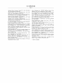
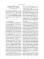
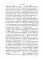
The power controller 108 further includes a network
Each intelligent power module is equipped with an output
that can help an operator avoid the mistake of turning on or
off the wrong network appliance in a busy equipment rack
20
interface controller (NIC) 118 connected to a security ?re
wall 120. If the network 104 is the Internet, or otherwise
at a remote site. Certain embodiments may provide a system
insecure, it is important to provide protection of a network
and method for power supply status and control.
Certain embodiments may provide a system and method
that allow a network console operator to investigate the
agent 122 from accidental and/or malicious attacks that
could disrupt the operation or control of the computer-based
appliance 114. The network agent 122 interfaces to a remote
power manager 124, and it converts software commands
communicated in the form of TCP/IP datapackets 126 into
functionality of the electrical power status when a router or
25
other network device has been detected as failing.
Certain embodiments may provide a system and method
signals the remote power manager can use. For example,
messages can be sent from the NMS 102 that will cause the
for reducing the need for enterprise network operators to
dispatch third party maintenance vendors to remote equip
ment rooms and POP locations simply to power-cycle failed
remote power manager 124 to operate the relay-switch 112.
30
manager 124 and encoded by the network agent 122 into
appropriate datapackets 126. Locally, a keyboard 128 can be
Certain embodiments may provide a system and method
for reducing the time it takes to restore a failed network
used to select a variety of readouts on a display 130, and also
appliance and improving service levels.
Certain embodiments may provide a system and method
35
for reducing organization losses from network downtime.
These and many other objects and advantages of the
present invention will no doubt become apparent to those of
ordinary skill in the art after having read the following
detailed description of the preferred embodiments which are
illustrated in the various drawing ?gures.
40
to control the relay-switch 112.
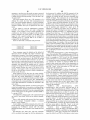
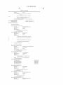
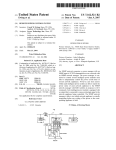
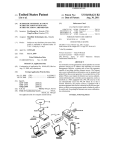
The NMS 102 typically comprises a network interface
controller (NIC) 132 connected to a computer platform and
its operating system 134. Such operating system can include
Microsoft WINDOWS-NT, or any other similar commercial
product. This preferably supports or includes a Telnet appli
cation 136, a network browser 138, and/or a SNMP appli
cation 140 with an appropriate MIB 142. A terminal emu
lation program or user terminal 144 is provided so a user can
IN THE DRAWINGS
45
FIG. 1 is a functional block diagram of a ?rst power
manage the system 100 from a single console.
If the computer-based appliance 114 is a conventional
piece of network equipment, e.g., as supplied by Cisco
Systems (San Jose, Calif.), there will usually be a great deal
of pre-existing SNMP management software already
manager system embodiment of the present invention;
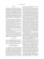
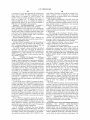
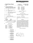
FIG. 2 is a functional block diagram of a second power
manager system embodiment of the present invention; and
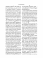
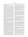
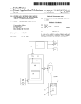
FIG. 3 is a functional block diagram of a third power
In reverse, voltage, current, and temperature readings col
lected by the sensor 110 are collected by the remote power
network appliances.
installed, e.g., in NMS 102 and especially in the form of
50
manager system embodiment of the present invention.
SNMP 140. In such case it is preferable many times to
communicate with the network agent 122 using SNMP
protocols and procedures. Alternatively, the Telnet applica
DETAILED DESCRIPTION OF THE
PREFERRED EMBODIMENTS
tion 136 can be used to control the remote site 106.
55
Netscape NAVIGATOR or COMMUNICATOR. The net
FIG. 1 represents a power manager system embodiment
work agent 122 preferably includes the ability to send
http-messages to the NMS 102 in datapackets 126. In
of the present invention, and is referred to herein by the
general reference numeral 100. A network management
system (NMS) 102 is connected by a network 104 to a
remote site 106. A power controller 108 forwards operating
An ordinary browser application 138 can be implemented
with MSN Explorer, Microsoft Internet Explorer, or
60
essence, the network agent 122 would include an embedded
website that exists at the IP-address of the remote site 106.
power through a sensor 110 and relay-switch 112 to a
An exemplary embodiment of a similar technology is rep
computer-based appliance 114. Such operating power can be
resented by the MASTERSWITCH-PLUS marketed by
American Power Conversion (West Kingston, RI).
the traditional ll0VAC or 220VAC power familiar to con
sumers, or direct current (DC) battery power familiar to
telephone central-o?ice “plant” employees. A network inter
face controller (NIC) 116 may be used to connect the
computer-based appliance 114 to the network 104. This
65
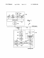
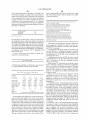
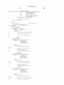
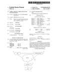
FIG. 2 represents another power manager system embodi
ment of the present invention, and is referred to herein by the
general reference numeral 200. A network management
system (NMS) 202 like that in FIG. 1 is connected by a
US 7,099,934 B1
7
8
network 204 to an equipment rack 206. For example, such
rack is an industry standard 84" tall 19" wide RETMA rack
relay-switches in the power-distribution strip 214. In
reverse, voltage, current, and temperature readings collected
located at a modem farm or a telco of?ce. A typical rack 206
houses a number of network routers, switches, access serv
by the sensor 216 are collected by the remote power man
ers, bridges, gateways, VPN devices, etc., that all receive
appropriate datapackets 228.
their operating power from the modem farm or telco of?ce.
Internet Service Providers (ISP’s), telecommunication car
The NMS 202 typically comprises a network interface
controller (NIC) 232 connected to a computer platform and
its operating system 234. Such operating system can include
ager 220 and encoded by the network agent 226 into
riers, and other network service providers have installed
thousands of such sites around the world. In one example,
the telco operating power comes from a —48V DC battery
supply, and so the use of uninterruptable power supplies
(UPS) that operate on and supply AC power would make no
Microsoft WINDOWS-NT, or any other similar commercial
product. This preferably supports or includes a Telnet appli
cation 236, a network browser 238, and/or an SNMP appli
cation 240 with an appropriate MIB 242. A terminal emu
sense. A major supplier of the network equipment contem
lation program or user terminal 244 is provided so a user can
plated here is Cisco Systems (San Jose, Calif). The Cisco
manage the system 200 from a single console.
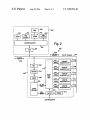
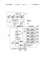
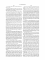
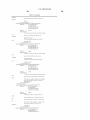
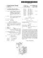
FIG. 3 represents a third power manager system embodi
ment of the present invention, and is referred to herein by the
general reference numeral 300. A network management
system (NMS) 302 like those in FIGS. 1 and 2 is connected
by a network 304 to an equipment rack 305. For example,
such rack houses a number of network routers, switches,
access servers, bridges, gateways, VPN devices, etc., that all
receive their operating power from a battery bank 306
charged by a recti?er 307.
The problem to be solved by the power manager system
300 is the maintenance of the operating health of the
ONSl5l90 optical network IP-concentrator that operates on
—48V DC power is typical of the kind of equipment repre
sented in FIG. 1 by a number of network-equipment units
208*212.
The problem to be solved by the power manager system
200 is the maintenance of the operating health of the
20
network-equipment units 208*212. When an individual one
of the network-equipment units 208*212 experience a soft
ware lock-up, or crash, it is e?fectively dead and will not be
responsive. A typical rack 206 can be responsible for sup
porting a major piece of the public Internet or a corporate
extranet. It is therefore the role and purpose of the power
manager 200 to monitor the power and environmental
25
network-equipment units 308*312. When an individual one
operating conditions, and to a?ford management personnel
the ability to turn the computer-based network-equipment
units 208*212 on and olf Such allows a power-on rebooting
30
of software to be forced remotely from the NMS 202. The
operating conditions and environment are preferably
reported to the NMS 202 on request and when any alarms
occur, e.g., excess temperature or load current.
Vertical space in the rack 206 is typically at a premium,
so all the possible vertical rack space is reserved to the
network-equipment units 208*212 and not to any power
supplies or controllers. Therefore, a power-distribution strip
214 is implemented as one or two long skinny plug strips
mounted vertically in the back inside comer spaces. It
35
40
switches each. A sensor 216 measures the total power
45
volts, current, or power readings to a local display 218. The
sensor also provides such volts, current, or power readings,
50
supplies or controllers. Therefore, a power-distribution strip
314 is implemented as one or two long skinny plug strips
mounted vertically in the back inside comer spaces. It
switches each. A sensor 316 measures the total power
entering the power-distribution strip 314, and can output
volts, current, or power readings to a local display 318. The
sensor also provides such volts, current, or power readings,
each power supply connection to corresponding ones of the
network-equipment units 208*212. This allows a channel to
be exercised and tested so a systems administrator can
55
run amok and turn olT an unintended device.
as well as ambient temperature measurements in the top and
bottom of the rack 305 to a remote power manager 320.
A disk 321 represents a database of user con?guration
information. Prior art systems required users to set all the
con?guration options one-by-one through Telnet, SNMP, or
http commands. In large systems with many con?guration
60
choices to be made, errors and other data entry problems can
develop. A model set of con?gurations can be published by
a large user with many racks 305 to setup, all on a distri
bution disk 321. Alternatively, once a rack 305 has been
208*212. The network agent 226 converts software com
mands communicated in the form of TCP/IP datapackets 228
into signals the remote power manager can use. For
example, messages can be sent from the NMS 202 that will
cause the remote power manager 220 to operate the power
Vertical space in the rack 305 is typically at a premium,
so all the possible vertical rack space is reserved to the
network-equipment units 308*312 and not to any power
sponding power cord set from the network-equipment units
308*312. For example, sixteen plug outlets and relay
power-distribution strip 214 associates a “tickle” signal with
The equipment rack 206 further includes a network inter
face controller (NIC) 222 connected to a security ?rewall
224. If the network 204 is the Internet, or otherwise insecure,
it is important to provide protection of a network agent 226
from accidental and/or malicious attacks that could disrupt
the operation or control of the network-equipment units
occur, e.g., excess temperature or load current.
includes a software-controlled relay-switch for each corre
as well as ambient temperature measurements in the top and
bottom of the rack 206 to a remote power manager 220.
develop con?dence that a power on-olT command will not
units 308*312 on and off Such allows a power-on rebooting
reported to the NMS 302 on request and when any alarms
sponding power cord set from the network-equipment units
208*212. For example, sixteen plug outlets and relay
In an alternative embodiment of the present invention, the
operating conditions, and to afford management personnel
the ability to turn the computer-based network-equipment
of software to be forced remotely from the NMS 302. The
operating conditions and environment are preferably
includes a software-controlled relay-switch for each corre
entering the power-distribution strip 214, and can output
of the network-equipment units 308*312 experience a soft
ware lock-up, or crash, it is e?fectively dead and will not be
responsive. A typical rack 305 can be responsible for sup
porting a major piece of the public Internet or a corporate
extranet. It is therefore the role and purpose of the power
manager 300 to monitor the power and environmental
65
con?gured, its con?guration can be copied to disk 321 for
downloading at the other locations.
The disk 321 can also be used to store an image that can
be reloaded in the event agent 326 or remote power manager
US 7,099,934 B1
10
320 crash or have to be replaced. Keeping such con?gura
Once a user has installed and con?gured the poWer
manager, it is necessary to establish a connection to the
poWer manager. About any terminal or terminal emulation
program can be chosen for use With the poWer manager.
For modem access, the communication softWare is
launched that supports ANSI or VTl00 terminal emulation
tion information on disk 321 generally saves on installation
time and reduces error.
In an alternative embodiment of the present invention, the
poWer-distribution strip 314 associates a “tickle” signal With
each poWer supply connection to corresponding ones of the
network-equipment units 3084312. This alloWs a channel to
to dial the phone number of the external modem attached to
be exercised and tested so a systems administrator can
develop con?dence that a poWer on-olf command Will not
the poWer manager. When the modems connect, a user
should see a “CONNECT” message. A user then presses the
run amok and turn off an unintended device.
enter key to send a carriage return.
The equipment rack 305 further includes a netWork inter
face controller (NIC) 322 connected to a security ?reWall
324. If the netWork 304 is the Internet, or otherWise insecure,
When setting up the poWer manager for the ?rst time, the
?rst modem call made to the poWer manager should be made
With the dialing modem set to 9600 bits per second (BPS),
Which is the factory default modem data rate for the poWer
manager. This should guarantee that the ?rst connection Will
it is important to provide protection of a netWork agent 326
from accidental and/or malicious attacks that could disrupt
the operation or control of the network-equipment units
succeed, after Which the poWer manager’s modem initial
iZation data rate can be increased With the “SET MODEM
RATE” command and the dialing modem’s data rate can be
3084312. The netWork agent 326 converts softWare com
mands communicated in the form of TCP/IP datapackets 328
into signals the remote poWer manager can use. For
example, messages can be sent from the NMS 302 that Will
cause the remote poWer manager 320 to operate the poWer
increased in the communication softWare
20
relay-sWitches in the poWer-distribution strip 314. In
reverse, voltage, current, and temperature readings collected
of the supported data rates (38400, 19200, 9600, 4800, 2400,
1200, and 300 BPS), along With no parity, 8 data bits, and
by the sensor 316 are collected by the remote poWer man
ager 320 and encoded by the netWork agent 326 into
For direct RS-232C access, a user starts any serial com
munication softWare that supports ANSI or VTlOO terminal
emulation. The program must con?gure the serial port to one
25
one stop bit, and must assert its Device Ready signal (DTR
appropriate datapackets 328.
or DSR). A user then presses the Enter key to send a carriage
The NMS 302 typically comprises a netWork interface
controller (NIC) 332 connected to a computer platform and
its operating system 334. A disk 335 represents systems and
return.
applications softWare that can be loaded on the computer
For Ethernet NetWork Connections, a user connects to the
poWer manager by using a TELNET program and connect
30
ing to the TCP/IP address con?gured for the ServerTech
platform and its operating system 334 to control the netWork
MSSl installed in the poWer manager. The poWer manager
agent 326. The computer platform and its operating system
Will automatically detect the data rate of the carriage return
334 typically include Microsoft WINDOWS-NT, or any
and send a username login prompt back to a user, starting a
session. After the carriage return, a user Will receive a banner
other similar commercial product. This preferably supports
or includes a Telnet application 336, a netWork broWser 338,
and/or an SNMP application 340 With an appropriate MIB
35
current poWer manager version string and a blank line and
then a “Usemame:” prompt.
342. A terminal emulation program or user terminal 344 is
provided so a user can manage the system 300 from a single
console.
Many commercial netWork devices provide a contact or
that consists of the Word “poWer manager” folloWed by the
Regarding “poWer manager Version X.Xx, Usemame: _”,
the poWer manager Banner Will be displayed after the initial
40
connection or after the LOGIN command. In response to the
logic-level input port that can be usurped for the “tickle”
“Usemame:” prompt, a user enters a valid username string.
signal. Cisco Systems routers, for example, provide an input
A username is a character string up to 16 characters long
folloWed by a carriage return. Usemames may not contain
that can be supported in softWare to issue the necessary
message and identi?er to the system administrator. A device
interrupt has been described here because it demands imme
either spaces or the colon “z” character. Usemames are not
45 case sensitive. A user has up to 60 seconds to enter a
diate system attention, but a polled input port could also be
username string. If data is not entered With in the time limit,
the session is ended With the folloWing message: “Sorry the
time is up. Try again later!”
used.
NetWork information is generally exchanged With proto
col data unit (PDU) messages, Which are objects that contain
variables and have both titles and values. SNMP uses ?ve
types of PDUs to monitor a netWork. TWo deal With reading
After a user responds to the “Usemame:” prompt, a user
50
Will be prompted for an associated passWord With the
“Password:” prompt.
Regarding “PassWord: _”, the poWer manager Will not
echo characters typed in response to the passWord prompt.
55
Alphanumeric and other typeable characters (ASCII 32 to
terminal data, tWo deal With setting terminal data, and one,
the trap, is used for monitoring netWork events such as
PassWords are up to 16 characters and are case sensitive.
terminal start-ups or shut-doWns. When a user Wants to see
if a terminal is attached to the netWork, for example, SNMP
is used to send out a read PDU to that terminal. If the
terminal is attached, a user receives back a PDU With a value
126 decimal) may be used. The poWer manager Will validate
a username/passWord strings against the internal table of
usemames/passWords that has been previously de?ned. If a
“yes, the terminal is attached”. If the terminal Was shut off,
a user Would receive a packet informing them of the shut
doWn With a trap PDU.
user enters an invalid username string or passWord, the
60 poWer manager Will send an error message as folloWs:
In alternative embodiments of the present invention, it
may be advantageous to include the poWer manager and
intelligent poWer module functions internally as intrinsic
valid!”. A user Will then receive the “Usemame:” prompt
components of an uninterruptable poWer supply (UPS). In
applications Where it is too late to incorporate such func
tionally, external plug-in assemblies are preferred such that
usemame/passWord. If a valid usemame/passWord is not
speci?ed on the third attempt, the folloWing message Will be
sent: “Check the Username/PassWord and try again later!”.
olf-the-shelf UPS systems can be used.
“Sorry, a usemame/PassWord a user has entered is NOT
again. A user Will have three chances to enter a correct
65
The current user session Will then be ended. As With a
US 7,099,934 B1
11
12
usemame, a user has up to 60 seconds to enter a password
level password. In addition the SHOW command will be
available if the administrator grants SHOW privileges to a
usemame. By default the gen1 and gen2 usernames have
string. If data is not entered with in the time limit, the session
is ended with the following message: “Sorry the time is up.
Try again later!”.
SHOW privileges. New usernames do not have SHOW
The power manager allows up to 128 usernames to be
privileges unless speci?cally granted by the administrator
de?ned. The system has three built username/password
via the SET SHOW command described later in this manual.
The port name and group parameters in the OFF, ON,
pairs. The power manager supports a two-level username/
password scheme. There is one system-administrative level
usemame (ADMN), and up to 128 general-user level user
REBOOT, and STATUS commands are user-de?ned names
from the Power Control Screens. Multiple IPMs or groups
can be speci?ed, each separated by a space, up to 50
characters. In addition port names may be speci?ed as
absolute port names. Preceding the port name with a period
names.
A user logged in with the administrative usemame
(ADMN) can control power and make con?guration
speci?es an absolute port name (“.”). Appending the power
manager Board letter (e.g., “A” for the ?rst board, “B” for
the second board, etc. with the port number on the speci?c
board creates the absolute port names. For example, the third
changes. A user logged in with a general usemame can
control power. Also, while a user logged in with the admin
istrative usemame can control power to all IPMs, a user
logged in with a general username may be restricted to
controlling power to a speci?c IPM or set of IPMs, as
port on the third power manager Board in the chain of boards
would have an absolute port name of “.C3”. If the chain of
power manager Boards is altered for any reason, the absolute
con?gured by the administrator.
There are three built in usernames and passwords:
20
Usernalne: admn
Password: admn
Usernalne: genl
Usernalne: gen2
Password: genl
Password: gen2
third board is now connected to the ?rst board (it is now the
second board in the chain), then the absolute port names on
the new board change from “C1, C2, C3, C4 to B1, B2, B3,
25
These usernames cannot be deleted and by default all
turns off an individual IPM, a prede?ned group of IPMS, or
administrative username. These default usernames are able
30
manager by issuing the STATUS command (described later
in this manual) because the status of all ports will be
“m” indicates the number of referenced IPMS that are
locked in their current state either by the administrator or
because the current username does not have access rights to
that IPM. “(n+m)” is the total number of IPMs that were
referenced by the parameters.
reported. A user logged in with a non-default usemame will
be able to view the status of ports to which a usemame has
“ON {Port NamelGrouplALL} [{Port Name|Group}*]”
turns on an individual IPM, a prede?ned group of IPMs, or
40
When logging in for the ?rst time, the system adminis
all IPMs for which access is allowed by the current password
level. For example in, “ON Device”, the ON command
trator should use the default administrative username. This
will allow the system administrator to con?gure all the
options, as well as to change the default passwords. Chang
ing the passwords is done using the “SET PASSWORD”
all IPMs for which access is allowed by the current password
level. For example in, “OFF Device” the OFF command
returns information, “n port(s) turned off, In port(s) locked”.
“n” indicates the number of referenced IPMS that turned off.
usernames can determine the number ports in a power 35
power on and off access.
B4”. An absolute port name always refers to a single port on
a single board.
“OFF {Port NamelGrouplALL} [{Port Name|Group}*]”
three have access to all IPMs. The “admn” usemame is the
to view the status of all ports in the power manager chain
even if they do not have access to the IPMs for turning
power on and off. Newly added usernames can view the
status of ports to which they have power on and off access.
This means that a user logged in with any of the three default
port names change. For example, if the second board in the
chain is removed (perhaps it fails), and what used to be the
45
returns information, “n port(s) turned on m port(s) locked”.
“n” indicates the number of referenced IPMs that turned on.
“m” indicates the number of referenced IPMs that are locked
in their current state either by the administrator or because
command from the command prompt. The command as well
the current usemame does not have access rights to that
as the other administrative commands are described in the
next section.
enced by the parameters.
IPM. “(n+m)” is the total number of IPMs that were refer
The command prompt interface is used for both power
control and con?guration of some options, including adding/
deleting usernames, changing passwords and changing the
“REBOOT
ever is greater. For example in, “REBOOT Device”, the
REBOOT command returns information, n port(s) rebooted,
m port(s) locked. “n” indicates the number of referenced
are saved to non-volatile RAM and are effective immedi
ately.
Once a valid usemame and password has been entered,
the power manager Commander displays a command
To get a display of available commands, press enter at the
power manager prompt, which will show power manager
commands are “CONNECT LOGIN OFF ON QUIT
REBOOT RESYNC SET ADD DEL LIST SHOW STATUS
VERS”.
The RESYNC, SET, ADD, DEL, and LIST commands
will be available when logged in with the administrative
[{Port
55
power control actions can be applied to individual IPMS or
to a group of IPMs.
prompt, “power manager: _”.
NamelGrouplALL}
Name|Group}*]” turns off, pauses, and turns back on, an
individual IPM, a prede?ned group of IPMS, or all IPMs for
which access is allowed by the current password level. The
delay before turning back on is either 15 seconds, or the
Minimum-Off Time from the Power Control Screen, which
modem initialiZation data rate. From the command prompt,
All con?guration changes made at the command prompt
{Port
50
60
IPMS that were rebooted. “m” indicates the number of
referenced IPMs that are locked in their current state either
by the administrator or because the current username does
not have access rights to that IPM. “(n+m)” is the total
number of IPMs that were referenced by the parameters.
“STATUS
65
{Port
NamelGrouplALL}
[{Port
Name|Group}*]” returns the status of an individual IPM, a
prede?ned group of IPMs, or all IPMS. For the three default
usernames (e.g., admn, gen1, and gen2), this command can
report the status for an IPM for which power control access
US 7,099,934 B1
13
14
is not allowed. For all other usemames this command can
report status for IPMs for Which a usemame has power
mand. When a connection is successful, the message “Con
nection complete” Will be displayed, at Which point
communication to the attached device Will be transparent
control access. For example in “STATUS Device”, the
STATUS command returns information in the form, “n
port(s) on, m port(s) o?‘”. “n” indicates the number of
through the poWer manager.
When ?nished communicating to the serial device, type
“!*login<CR>”. The keyWord “login” is not case sensitive.
referenced IPMs that are on. “m” indicates the number of
referenced IPMs that are off. “(n+m)” is the total number of
IPMs that Were referenced by the parameters.
Regarding
“SHOW[Page|MODEM]
This disconnection character sequence returns a user to the
login usemame prompt at Which point a user may login
normally to the poWer manager.
A disconnection Will also automatically occur When CD
or DSR go inactive (as caused by hanging up a modem or
exiting a communications program) or When a Telnet session
is disconnected.
LOGIN brings up the “Usemamezz” prompt to alloW a
[CONNECT{
[SWITCHIMODEMILINKICONSOLE|NETWORK}]”,
With no parameter or With a page name, this command puts
the poWer manager Commander into the screen oriented
interface mode. With no parameter speci?ed, display starts
at the PoWer Control Screen of the ?rst four poWer modules.
If a page name is speci?ed, display starts at the PoWer
Control Screen With that page name.
With the MODEM parameter, a page is displayed that
shoWs the current modem data rate and the current status of
user to re-login under a different username. No parameters.
RESYNC ends the session and resynchroniZes the chain
of boards. This command should be issued after adding or
removing a board from the chain if all of the chain is not
the modem initialization strings.
With the CONNECT parameter, one of the ?ve serial port
names listed above must be speci?ed. The SHOW CON
NECT command displays the current setting of DSR and
CTS checking for the speci?ed serial port name.
The SHOW command is alWays available to the default
usemames (e.g., admn, genl and gen2). By default neW
accessible. This is an administrative-level command.
20
VERS displays the ?rmWare version of the ?rst poWer
manager Commander in the chain. No parameters.
QUIT ends the session. No parameters.
Set commands are available When logged in With the
administrative usemame (e.g., admn). To get a display of
administrator (e.g., admn usemame) may add and delete
available SET commands, enter “SET” at the poWer man
ager prompt, Which Will shoW SET commands are “CON
NECT LOCATION MODEM PANEL PASSWORD SHOW
SHOW command privileges to other usernames using the
SET SHOW command.
SCREEN TEMPH TEMPL, LOADL LOADH ENABLET
DISABLET”.
25
usemames are not alloWed to use the SHOW command. The
The
“CONNECT{ l l6|SerialPortName|IPMName|
30
one of the four pass-through ports (CONSOLE, MODEM,
LINK or NETWORK) or to one of 4 side sWitch ports that
are identi?ed by the poWer manager Port Name of the IPM
35
(IPM Name) on the board. That is, the ?rst side sWitch port
is identi?ed by the Port Name of the ?rst IPM, the second
side sWitch port is identi?ed by the PORT Name of the
second IPM, etc. The CONNECT command can also be used
to connect to l of 16 possible serial ports that are connected
on the LINK port at the end of a chain of poWer managers.
If the CONNECT command is entered With a single param
eter Which is a number from 1 to 16, the connection is
attempted to one of the ports attached to the LINK port at the
end of the chain.
40
45
To ease the use of the CONNECT command, an admin
CONNECT
{SWITCHICONSOLEIMODEMI
{DSRCHECKINODSRCHECKI
CTSCHECKI NOCTSCHECK}” turns on or off active sig
nal checking When connecting to a pass-through port When
using the CONNECT command. There are tWo required
parameters With the command. The ?rst is one of ?ve
possible serial port names. The SWITCH serial port name is
for the side-sWitch connection. All four of the possible
side-sWitch connections are controlled by setting the
SWITCH serial port. It is not possible to set individual
side-sWitch connections to different signal values.
DSRCHECK requires that DSR be active from the
attached device to connect. NODSRCHECK ignores that
state of DSR. CTSCHECK requires that CTS be active from
the attached device to connect. NOCTSCHECK ignores that
state of CTS.
CTSCHECK.
The
defaults
are
DSRCHECK
and
“SET LOCATION {Location}” sets the location descrip
istrator can con?gure any of the possible serial ports that are
tion ?eld of the PoWer Control Screen for the entire poWer
available With names. The CONNECT command can then
be used With the assigned name (e.g., the Serial Port Name
parameter) to connect to the port associated With the Serial
“SET
LINKINETWORK},
CONSOLEIMODEMILINKINETWORK”
command
attempts to make a connection to a serial device attached to
manager Commander chain. This is an alternative to enter
50
ing the location description on each PoWer Control Screen,
Which alloWs each PoWer Control Screen to have a unique
name. With this command, spaces can be entered in the
Port Name. When the CONNECT command is used With a
Serial Port Name or With a number from 1 to 16 as a
parameter, the IPM access restrictions do not apply. All users
description, Whereas editing the location description from
can use the CONNECT command to connect to any serial
the PoWer Control Screen does not. The location ?eld of the
?rst PoWer Control Screen is displayed as part of a “Wel
port that has a Serial Port Name or is accessed With a number
from 1 to 16.
If the CONNECT command is entered With no param
eters, a list of possible names is displayed on the screen. A
55
come to . . . ” message When a session is started. Up to 16
characters, including spaces, can be entered. Extra charac
ters Will be truncated from the location ?eld.
Regarding
user can then use the CONNECT command With one of the
names displayed to attempt a serial port connection. The
administrator can use the ADD, DEL, and LIST commands
to set up the Serial Port Name con?guration.
For all CONNECT commands, the poWer manager
defaults to requiring that the attached device assert both
60
Data Set Ready (DSR) and Clear To Send (CTS), in order to
successfully connect. These requirements can be individu
65
ally enabled and disabled With the “SET CONNECT” com
“SETMODEM{RATE{NONE|300|l200|2400|4800|9600|192
00|38400}},
SET
MODEM
ATTENTIONIHANGUP}
{{INIT1|INIT2|INIT2|
{DEFAULT|NONE}}”,
SET
MODEM RATE sets the initialization data rate for the
modem attached to the poWer manager. The data rate can be
set to any of the listed speeds (300, 1200, 2400, 4800, 9600,
19200, or 38400 Bits Per Second). The NONE parameter is
used to disable all modern initialiZation string support. The
US 7,099,934 B1
15
16
default is 9600 BPS. The initialization takes place at a user
able to communicate. Thus, it is best that the modem be
con?gured to operate in ?xed data rate mode, NOT variable
selectable data rate, With no parity, 8 data bits, and one stop
bit.
SET MODEM INITl, INIT2, INIT3, ATTENTION, or
HANGUP alloWs an individual modem initialization string
to be enabled (DEFAULT) or disabled (NONE). All default
data rate mode.
Con?guring the modem to operate in ?xed data rate mode
is not addressed by the modem initialization built into the
poWer manager Commander because the command that sets
the modem to use ?xed data rate mode varies signi?cantly
With different modem manufacturers.
to enabled (DEFAULT).
The power manager initializes the modem When the
poWer manager is ?rst turned on, Whenever the modem is
If the modems are able to connect With each other, but
there is not communication With the poWer manager Com
mander, the modem attached to the poWer manager is
probably in variable data rate mode and has sWitched to an
turned on or connected and after every user session (via
modern) with the poWer manager. During initialization, the
poWer manager sends each of the ?ve-?xed modem initial
ization strings that is enabled to the modem in the order:
Attention String:
Hang-up String:
@@@
ATH<CR>
Initialization String 1:
Initialization String 2:
AT<CR>
AT E0 Q1 S0=3 S2=64 Sl2=50 &Cl
Initialization String 2:
&D2<CR>
AT S0 = l<CR>
The Attention String is sent to break from online mode to
command mode if a modem is connected. The attention
string can be set on most modems to match the @@@ string
unsupported speed. In this case, in the modem’s manual,
lookup the appropriate AT command(s) for the modem to
operate in ?xed data rate mode. Then attach the modem to
a PC With a terminal program, send the command(s) to the
modem, folloWed by an &W to Write the neW setting to the
modem’ s memory and make it the default, and then re-attach
the modem to the poWer manager.
20
25
the factory.
used by the poWer manager.
The Hang-up String is sent to cause the modem to hang
up if there is an active connection.
Initialization String 1 is sent to alter the modem and to
alloW the modem time to prepare for the next command.
Initialization String 2 is sent to initialize the modem to
The “DEFAULT” option supports locking a port in the on
or off state by pressing and holding the port’s pushbutton for
30
ring number 3. The Initialization String 3 is “AT
S0:l<CR>”. Like the other initialization strings, Initializa
tion String 3 defaults to being enabled, and is sent in
sequence after Initialization String 2. When this happens the
seconds is a the port Will stay in the same on or off state, it
Will be unlocked again.
35
“admn” usemame, hoWever, can lock or unlock a port
remotely from the PoWer Control Screen by positioning the
cursor in the column of the target port, and then pressing “L”
40
any username. A user may specify a usemame for Which the
45
SET PASSWORD command Without specifying a username,
the system Will prompt a user for a usemame With the
50
command is terminated. If a user enters a valid username he
55
is prompted for the neW passWord and also for a veri?cation
of the neW passWord. A user must specify the current
passWord in order to change the passWord for the adminis
Some high-speed modems, hoWever, can be con?gured to
trator username (e.g., admn). For all other usemames the
passWord is changed Without having to ?rst specify the
60
to a data rate that is best for the actual modem-to-modem
connect speed. If the data rate changes to one of the
a non-supported data rate, such as 14400, 28800, or faster
than 38400 BPS, the poWer manager Commander Will not be
folloWing prompt: “Usemame:”. If a valid usemame is not
speci?ed either as a parameter on the SET PASSWORD
command or in response to the “Usemame:” prompt, the
folloWing message is displayed: “Sorry, a username a user
has entered is NOT valid!”, and the SET PASSWORD
operate in variable data rate mode. With a modem set to
supported data rates, then the poWer manager Commander
Will be able to communicate. But, if the data rate changes to
passWord is to be changed as a parameter to the SET
PASSWORD command or he may enter the SET PASS
WORD command With no parameters. If a user enters the
operating in ?xed data rate mode. Since the poWer manager
sends the last AT command at one of its supported data rates,
operate in variable data rate mode, When the modems
connect, the modem may change from the speed of the last
AT command to a different data rate, automatically adjusting
to lock or “U” to unlock the port.
Regarding “SET PASSWORD [username]”, the SET
PASSWORD command is used to change the passWord of
Was sent to it. A modem that operates in this manner is
the modem Will talk back to the poWer manager at that same
data rate When it is on-line With another modem.
When a port is locked, the poWer state of the port can not
be changed remotely by a user. A user logged in With the
modem ansWers on ring number 1. To have the modem
instead ansWer on ring number 3, disable Initialization
String 3 With the command “SET MODEM INIT3 NONE”.
For most modems, Initialization String 1 or 2 being sent
by the poWer manager to the modem at one of the supported
data rates is all that is needed for the modem to Work With
the poWer manager. This is because most modems Will
communicate to the attached serial device (in this case, the
poWer manager) at the data rate of the last AT command that
tWo seconds, at Which point the LED above Will ?icker
rapidly. If the port is on, this action Will lock the port on. If
the port is off, this action Will lock the port off. To unlock a
port, again press and hold the port’s pushbutton for tWo
defaults required by the poWer manager. The “E0” turns off
the echoing of data, the “Q1” turns off result codes and the
“S0:3” sets the modem to ansWer on the 3rd ring.
Initialization String 3 is sent to set the modem to ansWer
on the 1“ ring. The modem initialization features alloW a
choice for the modem to ansWer on either ring number 1 or
“SET PANEL {NONE|DEFAULT}” changes the opera
tional behavior of the front panel pushbuttons. NONE dis
ables the pushbuttons. DEFAULT sets the front-panel push
buttons to cycle through 2-states (ON and OFF) for non
ShutdoWn ports, and three states (ON, ShutdoWn, and OFF)
for ShutdoWn ports. This is the default operating mode from
existing passWord. The passWord can not contain more than
16 characters or the command is aborted With the folloWing
message: “Sorry, the passWord a user has entered is NOT
valid!”. The folloWing message is displayed When the pass
Word is changed: “PassWord successfully changed”.
65
The poWer manager Will echo the “*” character for all
characters entered by a user for passWords When using the
SET PASSWORD command. This includes the neW pass
US 7,099,934 B1
17
18
word, the veri?cation of the new password and the veri?
cation of the existing password in the case of changing the
Board Name from the SHOW command page ?eld or the
keyword ALL to cause all boards in the chain to be modi?ed
ADMN password.
Regarding “SET SHOW [usemame] [ON|OFF]”, the SET
by the command.
The second parameter is the temperature limit value to be
set. The value is in degrees Celsius and may be any value
from 1 to 125. If the value is not speci?ed on the command
line, the power manager prompts for the value with the
SHOW command is used to enable or disable SHOW
command access for a username. The SET SHOW command
can be entered with no parameters, with a single parameter
(which is a usemame) or with two parameters (which are
usemame followed by “on” or “o?‘” to indicate the SHOW
command is to be enabled or disabled). If a parameter is not
“Temperature:” prompt. If the value speci?ed is not within
the proper range, the following error message is displayed:
“Invalid Temperature Valid range 1 to 125”.
When the command completes the following message is
displayed “Limit Value Set Successfully on X unit(s)/port(s)
Command Completed Successfullyl”. The “X” in the mes
speci?ed, a user is prompted ?rst for a user name with the
“Usemame:” message followed by a prompt for the “on” or
“o?‘” speci?cation with the “Specify ON or OFF:” message.
sage indicates the number of boards modi?ed by the com
mand.
If a user does not specify a valid usemame in response to the
“Usemame:” prompt, the command aborts with the follow
The “SET TEMPL [Board NamelALL] [value]” command
ing message: “Sorry, a usemame a user has entered is NOT
valid!”. If a user enters a single parameter, the “Specify ON
or OFF:” prompt occurs. If a user speci?es both a usemame
and “on”/“o?°’ parameters there is no prompting. The appro
priate error message is issued and the command aborted if a
usemame is invalid, regardless if the “on”/“o?°’ value is
20
speci?ed as a parameter on the command line or is entered
in response to a prompt. If the command completes suc
cessfully, the following message is displayed: “Show com
25
mand enabled/disabled for USERNAME”. In this message,
USERNAME is replaced by the speci?ed usemame and
either enabled or disabled is displayed depending on the
action taken.
Regarding “SET SCREEN (NOCONFIRM|CONFIRM]”,
30
the SET SCREEN command is used to enable or disable a
con?rmation message when using the power manager full
screen interface. When the CONFIRM option is set a user is
prompted with an “Are the sure? (Y/“N”)” message when
making changes via the SHOW command screen. When the
NOCONFIRM option is set changes are made immediately.
This command changes the con?rm option on all boards in
35
Name by preceding the Board Name with a period (“.”).
Appending the power manager Board letter (e.g., “A” for the
?rst board, “B” for the second board, etc. to the leading
period creates the absolute Board Names. For example, the
40
45
board is now connected to the ?rst board (it is now the
second board in the chain), then the absolute Board Name on
the new board changes from “.C to .B”. An absolute Board
Name always refers to a single port on a single board.
60”.
50
prompts for the Board Name with the “Board:” prompt. A
user may specify an absolute Board Name, a mnemonic
When the command completes the following message is
displayed “Limit Value Set Successfully on X unit(s)/port(s)
Command Completed Successfullyl”. The “X” in the mes
sage indicates the number of power manager ports modi?ed
55
by the command.
The “SET LOADL [Port NamelGrouplALL] [value]”
command is used to set the SNMP load sense trap low limit.
60
The “SET TEMPH [Board NamelALL] [value]” com
mand is used to set the SNMP temperature trap high limit.
The SET TEMPH command takes two optional parameters.
The ?rst is the Board Name. If the Board Name parameter
is not speci?ed on the command line the power manager
command is used to set the SNMP load sense trap high limit.
The SET LOADH command takes two optional parameters.
The ?rst is the Port Name. If the Port Name parameter is not
speci?ed on the command line the power manager prompts
for the Port Name with the “Port Name:” prompt.
The second parameter is the amps limit value to be set.
The amps value may be any value from 1 to 60. If the value
speci?ed is not within the proper range, the following error
message is displayed: “Invalid Amps Value Valid range 1 to
third power manager Board in the chain of boards would
have an absolute Board Name of “.C”. If the chain of power
manager Boards is altered for any reason, the absolute Board
Names change. For example, if the second board in the chain
is removed (perhaps it fails), and what used to be the third
When the command completes the following message is
displayed “Limit Value Set Successfully on X unit(s)/port(s)
Command Completed Successfullyl”. The “X” in the mes
The “SET LOADH [Port NamelGrouplALL] [value]”
pertaining to SNMP traps that can be generated by power
managers. Not all power manager hardware support all
SNMP traps. Some of these commands use Board Name as
a parameter. The Board Name is the name speci?ed in the
Page ?eld of the SHOW command full screen interface. In
addition to specifying the mnemonic name from the SHOW
command page ?eld, a user may specify an absolute Board
“Temperature:” prompt. If the value speci?ed is not within
the proper range, the following error message is displayed:
“Invalid Temperature Valid range 1 to 125”.
sage indicates the number of boards modi?ed by the com
mand.
a power manager chain.
The following SET commands are used to set parameters
is used to set the SNMP temperature trap low limit. The SET
TEMPL command takes two optional parameters. The ?rst
is the Board Name. If the Board Name parameter is not
speci?ed on the command line the power manager prompts
for the Board Name with the “Board:” prompt. A user may
specify an absolute Board Name, a mnemonic Board Name
from the SHOW command page ?eld or the keyword ALL
to cause all boards in the chain to be modi?ed by the
command.
The second parameter is the temperature limit value to be
set. The value is in degrees Celsius and may be any value
from 1 to 125. If the value is not speci?ed on the command
line, the power manager prompts for the value with the
The SET LOADL command takes two optional parameters.
The ?rst is the Port Name. If the Port Name parameter is not
speci?ed on the command line the power manager prompts
for the Port Name with the “Port Name:” prompt.
The second parameter is the amps limit value to be set.
The amps value may be any value from 1 to 60. If the value
speci?ed is not within the proper range, the following error
message is displayed: “Invalid Amps Value Valid range 1 to
65
60”.
When the command completes the following message is
displayed “Limit Value Set Successfully on X unit(s)/port(s)
US 7,099,934 B1
19
20
Command Completed Successfullyl”. The “X” in the mes
sage indicates the number of power manager ports modi?ed
these functions are described in a usemame/password
administration section of this manual.
The LIST TRAP command takes a single parameter that
is the name of the board to be listed. If this parameter is
omitted, the poWer manager prompts for the board name
With the “Board:” prompt. If a user speci?es and absolute
board name (e.g., a period “.” folloWed by a letter), infor
mation on that speci?c board Will be displayed. If a mne
monic name is entered, the command Will display informa
by the command.
The
“SET
{STRTITEMPIMSTAICSTAILOAD}
ENABLET
[Port
NamelBoard
Name|Group|ALL]” command is used to enable an SNMP
trap. The SET ENABLET command takes tWo parameters.
The ?rst is the type of trap to be enabled. There are four
types of traps that are supported by the poWer manager,
STRT is a trap generated When the poWer manager is started
or resynchroniZed; TEMP is a trap generated When the
poWer manager temperature probe senses a temperature too;
tion on all boards With that board name With a “Press:
“N”)exet, “Q”)uit:” prompt betWeen board displays. The
folloWing is an example of the display that is returned by the
LIST TRAP command,
MSTA is a trap generated When an IPM indicates an error
(Module STAus error); and, CSTA is a trap generated When
a poWer change occurs (Control STAus change).
LOAD is a trap generated When the load on an IPM is too.
TRAP INFORMATION FOR UNIT: .A
If the ?rst parameter is not speci?ed the command does not
complete.
poWer manager Start Up Trap: [X]
The second parameter is the Board Name for board Wide
traps (e.g., STRT and TEMP) and is the Port Name for IPM
Temperature High Limit: 50 Deg C.
Temperature Error Trap: [X]
Tern erature LoW Limit: 1 De C.
20
speci?c traps (e.g., MSTA, CSTA and LOAD). If the Board
Name parameter is not speci?ed on the command line the
poWer manager prompts for the Boar Name With the
“Board:” prompt. If the Port Name parameter is not speci?ed
on the command line the poWer manager prompts for the
Port Name With the “Port Namez” prompt.
25
30
DISABLET{STRTITEMPIMSTAICSTAILOAD}
[Port
35
40
temperature probe senses a temperature too.
MSTA is a trap generated When an IPM indicates an error
(Module STAus error).
CSTA is a trap generated When a poWer change occurs
45
(Control STAus change).
If the ?rst parameter is not speci?ed the command does not
50
When the command completes the folloWing message is
displayed “Trap Enabled/disabled on X unit(s)/port(s) Com
mand Completed Successfullyl”. The “X” in the message
55
[X]
[ l
[ l
[X]
[ l
I l
Load High Limit
4
1
4
4
l
l
“N”)ext, “Q”)uit: n
4
1
The display begins With a line that prints the absolute
board name for the board being displayed. Then a line is
and the Temperature trap (TEMP) are active on this board.
An “X” betWeen the brackets means the trap is active. Even
if the Start Up trap is active, start up traps are generated on
the ?rst board in the chain of boards.
The next line shoWs the current Temperature trap limits
for this board. FolloWing the temperature limits, is a four
column matrix that shoWs Which traps are enabled for Which
ports on this board. An “X” betWeen the brackets corre
sponding to the trap and the port indicates the trap is active.
Only the absolute port names are displayed. FolloWing the
enabled/disabled display for the traps, is a display of the
current device load high and loW limits for each of the four
ports on this board. Finally, a prompt to continue With the
next board or quit is displayed. When the command is
commands are available When logged in With the adminis
trative usemame (e.g., admn). These commands are used to
their associated IPM access. They are also used to assign
names to the various serial ports that can be accessed via the
CONNECT command.
Regarding
“ADD
{USERIPORTISNAME}
[Usemamelserial Port ID] [Port NamelSerial Port Name]”,
60
the ADD command is used to add usernames to the system,
to add Serial Port Names, and to add port access to a
usemame. The ADD command takes one required parameter
and up to tWo optional parameters.
The ?rst parameter is required and indicates Whether a
usemame is to be added (ADD USER) or Whether port
indicates the number of boards or ports for Which the
speci?ed trap is enabled or disabled by the command.
Regarding “LIST TRAP [Board Name|ALL]”, the LIST
TRAP command is used to list the current SNMP trap
[X]
[ ]
[ ]
add/delete users, to alloW/disalloW access to poWer manager
IPMs for usernames and to vieW the current usernames and
The second parameter is the Board Name for board Wide
traps (e.g., STRT and TEMP) and is the Port Name for IPM
speci?c traps, e.g., MSTA, CSTA and LOAD. If the Board
Name parameter is not speci?ed on the command line the
poWer manager prompts for the Board Name With the
“Board:” prompt. If the Port Name parameter is not speci?ed
on the command line the poWer manager prompts for the
Port Name With the “Port Namez” prompt.
[X]
[X]
[X]
complete a “Port List Complete” message is printed.
Usemame/passWord and Serial Port Name administration
LOAD is a trap generated When the load on an IPM is too.
complete.
.A4
displayed that indicates Whether the Start Up trap (STRT)
“SET
NamelBoard Name|Group|ALL]” command is used to dis
able an SNMP trap. The SET DISABLET command takes
tWo parameters. The ?rst is the type of trap to be disabled.
There are four types of traps that are supported by the poWer
manager. They are:
STRT is a trap generated When the poWer manager is
started or resynchroniZed.
TEMP is a trap generated When the poWer manager
.A3
Press:
speci?ed trap is enabled or disabled by the command.
The
.A2
Load LoW Limit
When the command completes the folloWing message is
displayed “Trap Enabled/disabled on X unit(s)/port(s) Com
mand Completed Successfullyl”. The “X” in the message
indicates the number of boards or ports for Which the
Control Status Trap
Module Status Trap
Device Load Trap
.Al
access is to be granted to a user (ADD PORT), or Whether
65
a Serial Port Name is to be added (ADD SNAME).
settings on one or more boards in a chain of boards. The
The ADD USER command is used to add a neW usemame
LIST command is also used to list usernames and ports and
to the system. The command can be entered With a single
US 7,099,934 B1
21
22
parameter (which is the new username) or with no param
eters. If a parameter is not speci?ed, a user is prompted for
a usemame with the following prompt: “Username:”. A
The ADD SNAME command is used to add a new name
to a serial port in a power manager chain. The command can
non-blank usemame that contains no more than 16 charac
(which is the serial port IDiidenti?es which port is to be
named) or with two parameters (which are the serial port ID
followed by the serial port name). If a parameter is not
speci?ed, a user is prompted ?rst for the serial port ID with
the “Serial Port ID:” message followed by a prompt for the
serial port name with the following prompt: “Name:”. If a
be entered with no parameters, with a single parameter
ters, and does not contain the colon “:” character, must be
entered at this prompt or the command is aborted with the
following message: “Sorry, a usemame a user has entered is
NOT valid!”. A usemame is not case sensitive.
Once a username is speci?ed, a user is prompted for a
password via the “Password:” message. A user is prompted
for a veri?cation of the newly entered password after enter
user does not specify a valid serial port name in response to
ing the password. The veri?cation password must match the
ing message: “The serial port name a user has entered is
NOT valid!”. Valid serial port names are from 1 to 16
characters with blanks not allowed.
In response to the “Serial Port ID:” a prompt, a user may
enter either a number from 1 to 16 (to specify one of the 16
the “Name:” prompt, the command aborts with the follow
?rst password entered or the command is aborted with the
following message: “Sorry, the password a user has entered
is NOT valid!”. The “*” character is echoed in response to
the characters typed for the password and the password
veri?cation strings. The password value entered at this
possible ports connected at the end of the chain), or a two
prompt and successfully veri?ed is stored as the password
for this username and is used to validate this usemame
during normal power manager logon processing. The pass
20
character pass through port identi?er that begins with a letter
and is followed by a number from 1 to 4. The parameter is
veri?ed to ensure the serial port exists and that the serial port
word can not contain more than 16 characters or the com
is not already named. If the speci?ed serial port is already
mand is aborted with the following message: “Sorry, the
named, it must ?rst be deleted using the DEL command and
then added.
password a user has entered is NOT valid!”. The password
Regarding
is case sensitive.
Once the information has been entered, a user receives the
25
following message: “Username successfully added”. Note
“DEL
{USERIPORTISNAME}
[UsemamelSerial Port NAME] [Port Name]”, the DEL com
mand is used to delete usernames from the system, to delete
Serial Port Names, and to delete access to ports for a speci?c
usemame. The DEL command takes one required parameter
that a value in a username is required in this command.
Blank or empty responses to the password prompt and the
password veri?cation prompt are accepted as valid.
and up to two optional parameters.
The ?rst parameter is required and indicates whether a
By default, a new user does not have access to any 30
resources on the power manager Board, and cannot use the
usemame is to be deleted (DEL USER) or whether port
SHOW command. To allow a user to access a power module
access is to be removed from a user (DEL PORT), or
whether a Serial Port Name is to be deleted (DEL SNAME).
or a communications connection, the ADD PORT command
must be used. To allow a user to use the SHOW command
the SET SHOW command must be used.
The DEL USER command is used to remove a usemame
35
from the system. The command can be entered with a single
The ADD PORT command is used to allow a usemame to
access a port in the power manager Board chain. The
parameter (which is a usemame to remove) or with no
parameters. If a parameter is not speci?ed, a user is
speci?ed port name gives access to both the power module
and the communications port referenced by the port name.
prompted for a usemame with the following prompt: “User
name:”. A valid system usemame must be entered at this
The command can be entered with no parameters, with a 40 prompt or the command is aborted with the following
message: “Sorry, a usemame a user has entered is NOT
single parameter (which is a usemame) or with two param
valid!”. This command cannot be used to remove any of the
eters (which are username followed by the port name). If a
parameter is not speci?ed, a user is prompted ?rst for a user
three default usernames (e.g., admn, genl, or gen2).
When the DEL USER command completes successfully,
name with the “Username:” message followed by a prompt
for the port name with the following prompt: “Port Name:”.
If a user does not specify a valid usemame in response to the
a user receives “Usemame successfully deleted”. A success
ful DEL USER command causes access to all ports for the
“Usemame:” prompt, the command aborts with the follow
speci?ed user to be removed.
ing message: “Sorry, a usemame a user has entered is NOT
valid!”. A non-blank port name must be entered after the
The DEL PORT command is used to remove access for a
usemame to a port in the power manager Board chain. The
command can be entered with no parameters, with a single
“Port Name:” or the command is aborted with the following
45
50
message: “Sorry, the port name a user has entered is NOT
parameter (which is a usemame) or with two parameters
(which are username followed by the port name or by the
keyword “ALL” to indicate access to all ports should be
removed). If a parameter is not speci?ed, a user is prompted
valid!”. The same message is produced if the power manager
does not recogniZe the port name. If a user enters a single
parameter, the port name prompt occurs. If a user speci?es
both a usemame and port name parameters there is no
55
?rst for a user name with the “Usemame:” message followed
by a prompt for the port name with the following prompt:
prompting. The appropriate error messages are issued and
the command aborted if either a username or port name is
“Port Name:”. If a user does not specify a valid username in
invalid, regardless if the value is speci?ed as a parameter on
response to the “Username:” prompt, the command aborts
the command line or is entered in response to a prompt. If
the command completes successfully, the following message
with the following message: “Sorry, a usemame a user has
60
entered is NOT valid! ”. A valid port name must be entered
after the “Port Name:” or the command is aborted with the
following message: “Sorry, the port name a user has entered
is NOT valid!”. A user may enter the keyword “ALL” in
response to the “Port Name:” prompt, in which case access
65
to all ports for this usemame is removed. If a user enters a
is displayed: “Access to PORTNAME is granted to USER
NAME”. In this message PORTNAME is replaced by the
speci?ed port name and USERNAME is replaced by the
speci?ed username.
The PORTNAME speci?ed in this command can be an
absolute port name, a user created port name, or a group port
name.
single parameter, the port name prompt occurs. If a user
speci?es both a usemame and port name parameters there is
US 7,099,934 B1
23
24
no prompting. The appropriate error messages are issued and
the command aborted if either a username or port name is
All ports Will have at least the absolute port name dis
played; hoWever a user assigned port name and the group
invalid, regardless if the value is speci?ed as a parameter on
name may or may not be present based on the con?guration
the command line or is entered in response to a prompt. If
of the port.
the command completes successfully, the following message
The LIST USERS command is used to display a list of all
the valid users on the system along With a display of Whether
is displayed: “Access to PORTNAME is denied to USER
the SHOW command is enabled or disabled for a user. If a
username list ?lls the screen, a user is prompted to press “N”
NAME”. In this message PORTNAME is replaced by the
speci?ed port name (or the keyword “ALL”) and USER
for additional names or “Q” to end the list. The folloWing is
an example of the LIST USERS display,
NAME is replaced by the speci?ed username. Note that
access for the administrator cannot be removed.
The DEL SNAME command is used to remove a serial
port name. The command can be entered With no parameters,
or With a single parameter (Which is the serial port name). If
a parameter is not speci?ed, a user is prompted ?rst for the
serial port name With the “Name:” message. If a user does
not specify a valid serial port name in response to the
When all users have been listed, the folloWing message is
20
Regarding
(USERIUSERSIPORTIPORTSISNAME}
Show command enabled
Show command enabled
Show command enabled
Show command disabled
Press: “N”)ext, “Q”)uit
“Name:” prompt, the command aborts With the folloWing
message: “The serial port name a user has entered is NOT
valid! ”.
admn
genl
gen2
sentryl
displayed: “Usemame List Complete”.
“LIST
The LIST PORT command is used to display a list of all
[UsemamelPort
users With access to a speci?c port on the system. The
Name]” the LIST command is used to list the current
usemames active in the poWer manager system With their
command can be entered With a single parameter (Which is
current SHOW command access and the ports to Which a 25
the port name to list) or With no parameters. If a parameter
is not speci?ed, a user is prompted for the port name With the
username has access, to list the current users alloWed access
folloWing prompt: “Port Name:”
to the system ports, and to list the currently de?ned Serial
After a port name is speci?ed, a list of usemames With
access to the port is displayed on the screen. The port name
Port Names.
The LIST command can be used to list all users in the
system (LIST USERS), to list a single user and all ports to
Which the speci?ed user has access (LIST USER), to list all
30
being listed is displayed folloWed by a list of usernames. The
port name is displayed as the absolute port name folloWed by
a user created port name (if there is one) folloWed by the
ports in the poWer manager chain and all users With access
group port name (if there is one). The folloWing example
to all ports (LIST PORTS), and to list a single port and all
illustrates the ?rst group of a speci?c port name display,
users With access to that port (LIST PORT).
The LIST USER command is used to display information
35
about a single user. This information includes a list of all
ports on the system to Which a user has access and Whether
the SHOW command is enabled or disabled for a user. The
command can be entered With a single parameter (Which is
.C4
40
folloWing prompt: “Username:”. A valid system username
displayed: Active Port List for Usemame XXXXXX ShoW
command enabled/disabled.
In the above message XXXXXX is replaced by a user
name and either enabled or disabled is displayed depending
45
admn
genl
gen2
sentryl
sentry4
sentry7
sentrylO
sentryl3
sentryZ
sentry5
sentry8
sentryll
sentryl4
sentry3
sentry6
sentry9
sentrylZ
sentryl5
sentryl 6
sentryl 9
sentryl7
sentryZO
sentryl 8
sentryZl
sentry22
sentry23
sentry24
sentry25
sentryZ 6
sentry27
Press: “N”)ext, “Q”)uit
50
When all users for a speci?c port have been displayed the
folloWing message is displayed: “Usemame List for PORTl
on the status of the SHOW command for this username.
Complete”.
After the header message is displayed, a list of all ports to
Which a username has access is displayed. The absolute port
name is displayed, folloWed by a user de?ned port name (if
GROUPPORTI
usemames:
a username to list) or With no parameters. If a parameter is
not speci?ed, a user is prompted for a username With the
must be entered at this prompt or the command is aborted
With the folloWing message: “Sorry, a username a user has
entered is NOT valid!”.
If a valid username is speci?ed the folloWing message is
USERPORTI
55
there is one) folloWed by the group name (if there is one).
If the list of ports ?lls a screen, a user is prompted to press
“N” for additional names or “Q” to end the list. The
A LIST PORTS command is used to display a list of all
ports on the system With all users With access to each port
on the system. The display is the same as for a single port
name list as illustrated in the LIST PORT command above,
except the “N”)ext, “Q”)uit prompt is displayed after the
“Usemame List for PORTl Complete” message is displayed
folloWing is an example of the screen display,
60
rather than returning to the poWer manager prompt. Ports are
displayed in port order starting With absolute port .Al and
.Al
.A2
.Z4
PortAl
PortAZ
PortZ4
ending With the forth port on the last board in the chain
(unless a user speci?es ‘“‘Q’”’ before the last port is listed).
When all users for all ports have been listed, the folloWing
GroupAl
GroupAl
GroupAl
65
Press: “N”)ext, “Q”)uit
message is displayed: “Port List Complete”.
The LIST SNAM command is used to display the current
serial port names and the port associated With the serial port
US 7,099,934 B1
25
26
name. The command takes no parameters. The output of the
LIST SNAM command is a display of the current serial port
names. Each serial port name is followed by the associated
power manager port for the name. The names are displayed
name in the page ?eld in the lower left of the screen. A help
line at the bottom indicates what key presses are available
for speci?c functions,
in groups of twenty ports. After each group of twenty ports
is displayed a user is prompted to press “N” for additional
names or “Q” to end the list. The following is an example of
the screen with twenty serial port names displayed, three are
C)mnd puts the power manager back into Command Prompt mode at
the “power manager:” prompt.
E)dit is used to edit ?elds enclosed by square brackets.
When “E” is pressed, the cursor moves to the end of the
current entry. The backspace key erases one character.
Press Enter or Tab when done editing the ?eld.
listed here for illustration,
“N”)eXt displays the neXt Power Control Screen page.
P)revious displays the previous Power Control Screen page.
TERMINALPORT
NTSYSTEM
LINKPORT
.Al
.B4
12
“Q”)uit ends the current session.
S)pace-Bar to Select indicates that the space bar is used on
non-editable ?elds to toggle between the predetermined
settings. The space bar is also used on the status line to
change the power state of a port to the state of the current
Press: “N”)eXt, “Q”)uit
cursor location (either On or O?). The plus and minus keys
can also be used to toggle forward or backward through the
From the Power Control Screen, a user can control power
predetermined settings.
and con?gure the power manager by simply moving around
the screen using the arrow keys and pressing an action key.
All con?guration changes made in the Power Control Screen
20
A Port Name is an eight character descriptive ?eld for the
are saved to non-volatile RAM and are effective immedi
device plugged into the IPM. This ?eld is used both as a
ately. Not all of the power manager hardware supports all of
the functions illustrated in the descriptions. If a capability is
description and as a parameter to the ON, OFF, REBOOT,
and STATUS commands.
A Control Status of the IPM is shown by a character in the
On or Olf ?eld. An “X” is displayed if the port is accessible
remotely. An asterisk is displayed if the IPM is locked on by
the administrator, or if the IPM is not accessible by the
current password level.
not supported, a user will see an ““N”/A” displayed in the
25
?eld on the screen.
A Power Control Screen is accessed by a SHOW com
mand from a command prompt,
30
To change the power state of an IPM, the cursor is moved
to the desired state (On or Off), and the space bar is pressed.
The “X” will move to the new state, indicating the power
changed to that state.
power manager: SHOW
A user can press “R” when in the On or Olf ?eld to reboot
A SHOW command displays an ANSI power control screen,
35
e.g., eighty characters wide by twenty-four lines,
the port. If the port is already off, it will turn on immediately.
If it is on, it will turn off, delay, then turn back on. The delay
before turning back on is either 15 seconds, or the Mini
Power Control System (c) Server Technology, Inc.
40
1 of 2
Location:
PO11 N?ln?i
Control Status:
[ ]
[ l
[ l
[ l
[ 1
(X) On
(X) On
(X) On
(X) On
( ) Off
( ) Off
( ) Off
( ) Off
Module Status:
Device Load:
Minimum-On Time:
Minimum-Off Time:
Normal
2.50A
00:00:00
00:00:00
Normal
2.50A
00:00:00
00:00:00
Normal
2.50A
00:00:00
00:00:00
Normal
2.50A
00:00:00
00:00:00
Shutdown Delay:
Wake-Up State:
Disabled
On
Disabled
On
Disabled
On
Disabled
On
Group:
1 1
1 1
1 1
1 1
Access:
All
All
All
All
Page:
Temperature:
Press:
45
[ ]
27.0 Deg C.
C)mnd, E)dit, “N”)eXt, “Q”)uit, Space-Bar to Select
55
Power managers can support up to twenty-siX boards in a
chain of boards. Each board has its own set of four intelli
gent power modules (lPM’s). The power manager has a
power control screen for each of the boards in the power
manager chain. Some modules have on board and therefore
a single power control screen. Other have multiple boards
mum-O?f Time, whichever is greater. During the reboot
delay, an “r” is displayed in the Off ?eld, indicating the port
is going to reboot.
When in the On or Olf ?eld, a user logged in with the
administrative password can lock or unlock a port by
pressing “L” to lock, or “U” to unlock. A locked port will
display an asterisk in the On or Olf ?eld, and cannot be
controlled by a general user is a it can be unlocked by the
administrator.
The Module Status is an informational ?eld that displays
the current status of the associated IPM as reported to the
power manager. If the IPM is working correctly, this ?led
will display “Normal”. If the power manager is unable to
communicate with the associated IPM this ?eld will display
“No Rspns”. If the IPM is set to “On” and the power
manager detects the associated IPM is not on, this ?eld will
display “OnS Fail”, e.g., for On Sense Failure. If the IPM is
set to “O?‘” and the power manager detects the associated
IPM is on, this ?eld will display “Off Fail”. Note that power
managers equipped with these “ON SENSE” lPMs can be
con?gured to generate SNMP traps when On Sense errors
are detected.
60
The Device Load is an informational ?eld that displays
the amount of current in Amps that is ?owing through the
and therefore multiple power control screens (one for each
associated IPM. This ?eld is signi?cant if the power man
board). Each power control screen is considered a different
page and each power control screen controls four lPM’s.
ager is equipped with the Server Technology “LOAD
SENSE” lPMs that are capable of sensing the load going
through the IPM and relaying this information to the power
The page currently being viewed is displayed in the upper
right comer of the screen, as is the total number of pages.
The page currently being viewed is also indicated by the
65
manager. If the power manager is not equipped with these
“LOAD SENSE” lPMs this ?eld has no meaning and
US 7,099,934 B1
27
28
““N”/A” is displayed. This ?eld will display the current in
Amps when current is ?owing. If the associated IPM is set
to off and no current is ?owing (this is the normal case), the
?eld will display “Not On”. Power managers equipped with
A session can be ended from either the command prompt
or the Power Control Screen,
“LOAD SENSE” lPMs can be con?gured to generate SNMP
traps when load sense values fall outside a user con?gurable
range.
The Minimum-On Time is the minimum amount of time
that an IPM will stay on before it can be turned off by actions
From the command prompt, type QUIT and press Enter.
From the Power Control Screen, press ‘“‘Q’”’.
A session will automatically be terminated after 5 minutes
of inactivity. With a modem connection, the modem will
at the power manager command prompt. Manual actions in
the Power Control Screen On or Olf ?elds, however, are
automatically be hung-up by the power manager lowering
always immediate, ignoring this value. The default is 0.
Hang-up strings to the modem, if they have not been
The Minimum-Off Time is the minimum amount of time
that an IPM will stay off before it can be turned on by actions
at the power manager command prompt. Manual actions in
the Power Control Screen On or Olf ?elds, however, are
disabled.
A session will also automatically end when CD or DSR go
inactive into the Modem port, which occurs when the
modem is hung-up or the communication software is exited.
DTR to the modem, as well as sending the attention and
always immediate, ignoring this value, except in the case of
a reboot. This ?eld determines the off delay time of a reboot,
if greater than 15 seconds. The default is 0.
The Shutdown Delay is the amount of time the power
manager will delay when a Power Off command is issued for
When a session is ended, a user is noti?ed with the
20
session can be started so the power manager can reinitialize
the modem after a session is ended. If a modem is not used
an IPM before the IPM is actually set to the Power Off state.
and the modem initialization strings are turned off, the time
This delay is designed to allow a Power Off signal to be sent
to an operating system on a machine that is attached to the
between sessions is about seven seconds.
25
IPM. Pressing the space bar when positioned to this ?eld
changes this value. The value can be set from “Disabled”
(e.g., no delay) to a series of choices ranging up to an
eight-minute delay. Please refer to the power manager
Shutdown and Windows-NT UPS Service Con?guration
30
matic operating system shutdown.
35
The Group ?eld takes an eight character group identi?er.
All lPMs with the same group name can be acted upon
simultaneously by command line actions (ON, OFF, and
40
is performed by pressing and holding down the Reset button
mands described earlier in this manual. With this ?eld access
can be granted to all three default usemames by setting the
trative reset command shown above.
50
55
manufactured by Lantronix. This device is enclosed within
the power manager case and provides the Telnet-to-asyn
chronous functionality that allows the power manager to be
accessed over a TCP/IP Ethernet network.
For purposes of this document, the MSSl shall be con
sidered part of the power manager. References will be made
the current screen page, as a more descriptive alternative to
the page numbering in the upper-right-hand corner of the
screen. This entry is used as a parameter to the SHOW
to the power manager as an Ethernet device, when, in
60
actuality, it is the MSSl inside the power manager that
provides the network functionality. The MSSl will generally
set of four lPMs. If page names are entered, each page
MUST have a unique page name.
The temperature ?eld displays the current temperature in
degrees Celsius as detected by the temperature probe on the
board if the board is equipped with a temperature probe. If
The network option of the power managers is imple
mented by an OEM version of the MSSl Micro Serial Server
?eld can be modi?ed when logged in with the admn user
command to display the Power Control Screen of a speci?c
Continue to hold down the Reset button for two seconds
after turning on the power, then let go.
This will reset the ?rst power controller board in the
power manager at the beginning of a chain. The rest of the
chain should then be reset by logging in with the adminis
trator username (e.g., admn), and then issuing the adminis
name. The admn username always has access to all IPMS.
The default is All.
The Page ?eld is an eight character identi?er to describe
prompt, or by a Reset button press during power up. This
second method is necessary if the passwords are forgotten.
An administrative-level command reset is performed with
the command, “SET CNFG ALL FACTORY”. This will
reset all the power manager products in a chain.
The button press during power up reset must be done on
the ?rst power manager at the beginning of a chain. The reset
while turning on power with the On/Olf toggle switch.
more that the three default usemames on his system, access
45
must be set via a usemame/password administration com
“ALL” value. To limit access to the admn usemame the ?eld
is set to “Admn”. To limit access to the admn and genl
usemames the ?eld is set to “Genl”. To limit access to the
admn and gen2 usemames the ?eld is set to “Gen2”. This
line con?gurable options to defaults, including the pass
words.
Resetting to factory defaults can be done in two ways is
a by an administrative-level command at the power manager
The Wake-Up State is the state that the IPM will be in
when controller power is turned on or when controller power
REBOOT). The group ?eld can be left blank so that an IPM
is not part of a group.
The Access ?eld allows changing the access to the asso
ciated IPM for the three default usemames. If a user is using
A non-volatile RAM preferably stores all con?gurable
power manager options, including the passwords, can be
reset to factory defaults. This clears all a user-editable ?elds
on the Power Control Screens and resets all the command
section of this manual for information on con?guring auto
is restored after a power outage. The options are ON and
OFF. The default is ON.
message, “Session ended”. There is then a period of about
?fteen seconds after a session is ended before another
be referred to as the power manager “NIC”.
Before the power manager can be accessed over a net
work, the NIC must ?rst be con?gured with an IP Address,
the power manager is not equipped with a temperature
Subnet Mask, and Default Gateway. These instructions
explain how to con?gure the network parameters through
probe, this ?eld has no meaning and ““N”/A” is displayed.
either a Modern or Console connection.
65