1
US007162521B2
(12)
(54)
United States Patent
(10) Patent N0.:
Ewing et a].
(45) Date of Patent:
US 7,162,521 B2
*Jan. 9, 2007
REMOTE POWER CONTROL SYSTEM
5,506,573 A *
4/1996 Ewing et a1. ............. .. 340/644
(75)
Inventors: Carrel W. Ewing, Reno, NV (US);
5,506,790 A
5,537,462 A
4/1996 Nguyen
7/l996 Utter et a1‘
_
(73)
Assignee: Server Technology, Inc., Reno, NV
(Us)
(*)
Notice:
Andrew J. Cleveland, Reno, NV (US)
_
5,717,934 A
5,721,934 A
2/1998 Pltt et a1.
_
2/1998 Scheurlch
Subject to any disclaimer, the term of this
patent is extended or adjusted under 35
U.S.C. 154(b) by 0 days.
(Continued)
Tlhis patent is subject to a terminal dis-
OTHER PUBLICATIONS
c a1mer.
(21)
Appl, No; 10/806,130
(22)
Filed:
Western Telematic, Inc., “RMM Rack Mount Data/Fax Modem,
WTI Part No. 12548 Rev. F, User’s Guide,” 15 pages, marked ©
Mar. 23, 2004
(65)
1998 and Sep. 1998.
Prior Publication Data
Us 2004/0215763 A1
(Continued)
001- 28, 2004
Primary Examinerilohn Follansbee
R l d U s A l_
_
D
6 ate
' ' PP lcatlon am
(60)
Assistant ExamineriAshok B. Patel
(74) Attorney, Agent, or FirmiKlarquist Sparkman, LLP
Continuation of application No. 10/758,117, ?led on
Jan. 16, 2004, noW Pat. No. 7,010,589, Which is a
division of application No. 09/375,471, ?led on Aug.
(57)
ABSTRACT
16, 1999, noW Pat. No. 6,711,613, Which is a con
tinuation'in'part of application N0~ 08/685,436, ?led
(51)
An SNMP network comprises a poWer manager With an
on Ju1~ 23’ 1996’ HOW Pat- NO~ 59492974
SNMP agent in TCP/IP communication over a network With
Int Cl
an SNMP netWork manager. The poWer manager is con
Got'sF 5/173
(200601)
n‘elcteli to gontrcg selveral itnteilltilgent powernmoigultest eacl;
(52)
(
)
G06F 1/26
(2006.01)
us. Cl. .................... .. 709/223; 361/601; 361/622;
713/340
several netWork aPP liances. PoWer-on and load sensors
Within each intelligent Power module are able to report the
poWer status of each netWork appliance to the SNMP
(58)
Field of Classi?cation Search ................ .. 307/34,
network manager With MIB variables in response to GET
307/35, 36, 37, 38, 11, 18, 31, 32, 43, 149,
Commands. Each intelligent poWer module is equipped With
(56)
a
e
O In epen en y Con r0
e power 0
O
S auS O
307/150; 361/601, 622; 713/340; 439/652;
an output that is connected to cause an interrupt signal to the
_
netWork appliance being controlled. The SNMP netWork
_
_
337/186
See aPPhCaUOn ?le for Complete Search hlstoryReferences Cited
manager is able to test Which netWork appliance is actually
responding before any cycling of the poWer to the corre
sponding appliance is tried.
U.S. PATENT DOCUMENTS
5,424,903 A
6/1995 Schreiber
33 Claims, 4 Drawing Sheets
10‘
56E’
(1
4
TCP/IP
*Elga
SNMP
POP
Ms‘
POP
22
[$012
,8
[a1 9 g E
'
“SW 152
m
'
5| 1
lII'UPl
911a
" "11' "W"
5.;
:22:
is
IPM 3‘
__|
‘PM
30
24
1
32
poweraonnec?cns
US 7,162,521 B2
Page 2
US. PATENT DOCUMENTS
Server Technology, Inc ., VersaTimer Operations Manual, Thank you
for purchasing the VersaTimer, 3 pages.
6,029,092
6,408,395
6,496,103
6,507,273
6,519,509
A
B1
B1
B1
B1
6,715,088 B1
2004/0047095 A1*
2/2000
6/2002
12/2002
1/2003
2/2003
Stein
Sugahara et al.
Weiss et al.
Chang et al.
Nierlich et al.
3/2004 Togawa
3/2004
Server Technology, Inc., VersaTimer, A 7-Day, Programmable
Power Scheduler, 1994, 2 pages.
Server Technology, Inc., Intel2 Power Modulei12v schematic,
Mar. 8, 1999, 1 page.
Reynolds et al. ........... .. 361/62
OTHER PUBLICATIONS
Server Technology, Inc., “VersaTimer Operations Manual, Thank
you for purchasing the VersaTimer,” 3 pages, marked © 1995.
MIRAPATH, A Cyclades Premier Partner, “AlterPath PM User
Guide,” 49 pages, marked © 2003 and Jun. 2003.
Western Telematic, Inc., “NPS Series Network Power Switch Mod
els NPS-115 & NPS-230, WTI Part No. 12927 Rev. C, User’s
Guide,” 19 pages, marked © 1999 and Jul. 1999.
Server Technology, Inc., “VersaTimer, A 7-Day, Programmable
Power Scheduler,” 2 pages, marked © 1994.
* cited by examiner
U.S. Patent
Jan. 9, 2007
Sheet 1 014
US 7,162,521 B2
_.
mom_10m/\,3
“E12.
nmm“=5\2nz=w2 m
32m:
$53\/\.\25 653.:3568
om“6m/W53Em5Ea“
wk.‘
fiv(@I'
wv
2.50318
mm. 2n:.
82n:Em? Sn:
mm
%
m,52.
1
mmV5E
mm:.( a_
Wm
on
5.652:
U.S. Patent
Jan. 9,2007
Sheet 2 M4
US 7,162,521 B2
Fig. 2
‘i001
iv
102
apply a series of alternating
current (AC) voltage pulses
to an appliance with an on/off
switch that are synchronized
to a source of AC power
l
sense the presence of any series of
AC current pulses that result
it the appliance switch is closed
analyze any murrent pulses detected
106
in step 104 to determine if
they resulted from the application
of the AC voltage in step 102
1
output an cnlotf status indication
for the appliance switch
l
108
U.S. Patent
Jan. 9, 2007
Sheet 3 0f 4
US 7,162,521 B2
network
4 tnmuumnm"mum-"n
A
W.vw.NQ.8.mmCwOZLw0I§.-OQ>
v:r.z5oremmw;
.~_y
n.
u
a
I8
.a.
5222080
8.3a.m
M
mm
m52E
-lnmmum
',.I-..-.1,tiI.l|..
883.Jun
0.A_
$2>9
ooj82$
\EI
"
nm
n.. .
=02‘.“
xma
mG.“
1.n2 21
Q26m
m
28
WI
.
QNND.m
:w>5
>L.nm"_'+
2 #m..mn.0 {5"IEm: &~\ESEr
_
no<>2w“
wak
“.
ill.
mv31
zJukl
_32i
or other source
“1Il‘no¢
O>3.5m
U.S. Patent
Jan. 9, 2007
Sheet 4 of4
US 7,162,521 B2
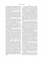
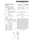
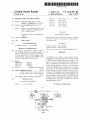
: neutraLout
236
Fig. 5
V_SENS
238
US 7,162,521 B2
1
2
REMOTE POWER CONTROL SYSTEM
reduce non-netWork costs, and that usually translates to
CO-PENDING APPLICATIONS
feWer technical people available in the right places to
support large and complex in-house global netWorks. Such
reduced repair staffs noW rely on a combination of central
ized netWork management tools and third-party maintenance
This is a Continuation application of US. patent appli
organizations to service their remote POP sites. The costs
cation Ser. No. 10/758,117 ?led Jan. 16,2004 now US. Pat.
No. 7,010,589 Which is a Divisional of US. patent appli
cation Ser. No. 09/375,471 ?ledAug. 16, 1999 now US. Pat.
No. 6,711,613 Which is a Continuation-In-Part of US. patent
associated With dispatching third-party maintenance techni
cians is very high, and the dispatch and travel delay times
can humble the business operations over a Wide area for
What seems an eternity.
application Ser. No. 08/685,436 ?led Jul. 23, 1996, now US.
Pat. No. 5,949,974 the contents of Which are hereby incor
Global communication netWork operators, located at a
porated by reference in its entirety.
feW centralized netWork management centers, are relying
more and more on automated netWork management appli
BACKGROUND OF THE INVENTION
cations to analyze, process, display and support their net
Works. An increasing number of netWork management soft
1. Field of the Invention
The invention relates generally to automatic poWer con
trol and more particularly to remote control methods and
Ware applications are being marketed that use open-system
devices to maintain computer netWork system availability.
2. Description of the Prior Art
Enterprise netWorks exist to support large World-Wide
organizations and depend on a combination of technologies,
e.g., data communications, inter-networking equipment
(frame relay controllers, asynchronous transfer mode (ATM)
sWitches, routers, integrated services digital netWork (ISDN)
controllers, application servers), and netWork management
application softWare. Such enterprise netWorks can be used
to support a large company’s branch of?ces throughout the
World, and, as such, these netWorks have become mission
critical to the functioning of such organizations. Masses of
information are routinely expected to be exchanged, and
standardized protocols. Particular netWork application tool
20
management protocol (SNMP) applications are convention
25
local and Wide area multivendor netWorks. OPENVIEW is a
and users With the ability to manage multivendor netWorks
30
and expand their distributed computing environments.
OPENVIEW alloWs netWork operation centers to build an
intelligent hierarchical network management application,
and uses open standards such as SNMP, user datagram
protocol (UDP), and the noW ubiquitous transmission con
35
trol protocol/internet protocol (TCP/IP). Because OPEN
VIEW is built on open system standards, global communi
cation netWork operators can easily integrate the various
headquarters.
A typical enterprise netWork uses building blocks of
router and frame relay netWork appliances mounted in
equipment racks. Such equipment racks are distributed to
remote point of presence (POP) locations in the particular
netWork. Each equipment rack can include frame relay
controllers, routers, ISDN controllers, servers and modems,
ally used to issue alarms to central management consoles
When remote netWork appliances fail.
One such SNMP netWork management application is
marketed by Hewlett-Packard. HP OPENVIEW is a family
of netWork and system management tools and services for
management platform that provides application developers
such information exchanges are necessary to carry on the
daily business of modern organizations. For example, some
international banks have thousands of branch of?ces placed
throughout Europe, Asia and the United States that each
critically depend on their ability to communicate banking
transactions quickly and ef?ciently With one another and
softWare is available to report lists of the netWork appli
ances, by location, and can issue trouble lists and keep track
of softWare versions and releases. NeW simple netWork
inter-networking equipment nodes into a managed environ
ment operated by strategically located netWork consoles.
40
In order to provide a reliable computing environment, a
robust and active process for problem resolution must be in
place. OPENVIEW alloWs the de?nition of thresholds and
monitoring intervals, and the interception of netWork, sys
tem, database, and application-messages and alerts. Once a
etc., each of Which are connected to one or more poWer 45 threshold value is exceeded, intelligent agents can run a
sources. The value of POP equipment can range from
pre-de?ned automatic action and/or generate and send a
$200,000 to $500,000, and the number of individual devices
message to alert an operator on a central management
console. Messages can also be forWarded to a pager or
can exceed a thousand.
Many enterprises rely on an uninterruptable poWer supply
(UPS) to keep their netWork appliances operational. Many
trouble-ticketing application. To help focus on the most
50
critical problems, a message broWser Win doW is used to
netWork appliances are typically connected to a single UPS,
display six severity levels for incoming problems and
and this sets up a problem. When an individual router locks
events, e.g., ranging from stable to critical. An integrated
up, the router’s poWer cannot be individually cycled on and
off externally at the UPS because it is connected to a
multiple poWer outlet. The recovery action choices available
to the netWork control center operator thus do not include
being able to reinitialize the individual equipment through a
poWer interruption reset. The netWork operator could com
mand the UPS to poWer cycle, but that Would reset all the
other attached devices that Were ostensibly operating nor
history database is provided for auditing and analyzing
system and netWork activities, for identifying trends and for
55
anticipating problems before they occur. Activity displays
and reports can be customized by the users.
Prior art SNMP netWork management uses embedded
microprocessors in almost every netWork appliance to sup
port tWo-Way inter-computer communications With TCP/IP,
mally and carrying other netWork traf?c. Another option is
of Which SNMP is a member of the TCP/IP protocol suite.
SNMP is conventionally used to send messages betWeen
to dispatch someone to the remote location to reset the
management client nodes and agent nodes. Management
locked-up device. Neither choice is an attractive solution.
information blocks (MIBs) are used for statistic counters,
port status, and other information about routers and other
In large organizations that have come to depend heavily
on enterprise netWorks, great pressures develop to control
costs and thus to improve pro?ts. Organizational doWn
sizing has been used throughout the corporate World to
60
65
netWork devices. GET and SET commands are issued from
management consoles and operate on particular MIB vari
ables for the equipment nodes. Such commands alloW net
US 7,162,521 B2
3
4
work management functions to be carried out between client
the node. For example, in a router based network with
equipment nodes and management agent nodes.
SNMP support, prior art individual routers can use SNMP to
issue an alarm to the management console. But the console
SNMP is an application protocol for network manage
ment services in the internet protocol suite. SNMP has been
adopted by numerous network equipment vendors as their
operator would know only that the router is failing. A GET
command can be issued to the router node to determine if the
counter and bulfer threshold limits were exceeded and
main or secondary management interface. SNMP de?nes a
client/server relationship, wherein the client program, a
“network manager”, makes virtual connections to a server
caused a router to lock-up. However, the console operator
does not have any information about the electrical power
status to the router, e.g., has the router power switch been
moved to the OFF position or has the switch been acciden
tally turned OFF? The electrical power source could have
failed, the power cable connection become loose, or a
technician may have accidentally removed the router from a
rack.
program, an “SNMP agent”, on a remote network device.
The data base controlled by the SNMP agent is the SNMP
management information base, and is a standard set of
statistical and control values. SNMP and private MIBs allow
the extension of standard values with values speci?c to a
particular agent. Directives issued by the network manager
client to an SNMP agent comprise SNMP variable identi?
ers, e.g., MIB object identi?ers or MIB variables, and
instructions to either GET the value for the identi?er, or SET
SUMMARY OF THE PRESENT INVENTION
the identi?er to a new value. Thus private MIB variables
allow SNMP agents to be customiZed for speci?c devices,
e.g., network bridges, gateways, and routers. The de?nitions
20
of MIB variables being supported by particular agents are
located in descriptor ?les, typically written in abstract syn
tax notation (ASN.1) format. The de?nitions are available to
network management client programs.
SNMP enjoys widespread popularity, and SNMP agents
25
are available for network devices including computers,
control and monitoring is thus possible.
Unfortunately, SNMP is a complicated protocol to imple
30
35
particularly ef?cient protocol. Bandwidth is often wasted
40
length and data descriptors scattered throughout each mes
sage. SNMP variables are identi?ed as byte strings, where
to the network appliance being controlled. The SNMP
actually responding before any cycling of the power to the
45
ticular network devices. But such data is easily acquired by
important information about the network includes the dif
ferences between devices, besides their current states.
SNMP affords a good mechanism for rapidly processing
such differences on large networks, since SNMP avoids the
processing burden of remote login and execution.
Network management applications can thus monitor the
health of every part of a global communications network and
GET commands. Each intelligent power module is equipped
network manager is able to test which network appliance is
Most vendors implement network managers thinking a
user’s primary interest is in the data associated with par
other means, e.g., “netstat” and “rsh” UNIX programs. The
network manager. The power manager is connected to
control several intelligent power modules each able to
independently control the power on/olf status of several
network appliances in an equipment rack at a common
remote node, e.g., a point-of-presence site. Power-on and
load sensors within each intelligent power module are able
to report the power status of each network appliance to the
SNMP network manager with MIB variables in response to
with an output that is connected to cause an interrupt signal
each byte corresponds to a particular node in the MIB
database. Such identi?cation leads to needlessly large data
handles that can consume substantial parts of each SNMP
message.
subjected to a power-up or power-down command before the
operator must commit to such commands.
Brie?y, an SNMP network embodiment of the present
invention comprises a power manager with an SNMP agent
in TCP/IP communication over a network with an SNMP
ment, due to complex encoding rules, and it is not a
with needless information, such as the SNMP version that is
to be transmitted in every SNMP message, and multiple
a central network management console.
It is a further object of the present invention to provide a
veri?cation of which particular network appliance will be
bridges, modems, and printers. Such universal support pro
motes interoperability. The SNMP management protocol is
?exible and extensible, SNMP agents can incorporate device
speci?c data. Mechanisms such as ASN.1 ?les allow the
upgrading of network management client programs to inter
face with special agent capabilities. Thus SNMP can take on
numerous jobs speci?c to device lasses such as printers,
routers, and bridges. A standard mechanism of network
It is therefore an object of the present invention to provide
a system and method for providing power supply status and
control in network nodes at geographically distant locations.
It is another object of the present invention to provide a
system and method for describing power supply status and
control in SNMP MIB variables between network nodes and
50
55
corresponding appliance is tried.
An advantage of the present invention is that a system and
method are provided that can help an operator avoid the
mistake of turning on or off the wrong network appliance in
a busy equipment rack at a remote site.
Another advantage of the present invention is that a
system and method are provided for describing power
supply status and control in SNMP MIB variables between
network nodes and a central network management console.
A further advantage of the present invention is that a
system and method are provided that allows a network
console operator to investigate the functionality of the
can be set to communicate alarms to a central management
electrical power status when a router or other network
console. Current network management applications do an
device has been detected as failing.
A still further advantage of the present invention is that a
system and method are provided for reducing the need for
adequate job of informing central management consoles
60
about the health of various nodes in the network and the
alarms they issue when a node is failing are useful.
enterprise network operators to dispatch third party main
Conventional SNMP network management technologies
tenance vendors to remote equipment rooms and POP loca
tions simply to power-cycle failed network appliances. The
do not provide suf?cient information related to the nodes’
electrical power status. A new technology is needed that can
be simply and inexpensively added to client equipment
nodes for SNMP reporting of the electrical power status of
65
costs to dispatch such third party maintenance vendor can
run from $300i$600 per call. The cost of implementing the
present invention can be recaptured in less than one year,
US 7,162,521 B2
5
6
e.g., by reducing the number of third party maintenance
only the four netWork appliances 38, 40, 42, 44, typical
dispatches to remote locations.
Another advantage of the present invention is that a
system and method are provided for reducing the time it
takes to restore a failed netWork appliance and improving
installations Will have so many that it is easy for the Wiring
of the poWer supply to get confused. In practice this has
happened often enough that serious consequences have been
paid When the netWork appliance that Was supposed to be
controlled by a particular IPM Was not. Given the depen
dence that customers, users, and suppliers noW place on the
service level measures.
Another advantage of the present invention is that a
uninterrupted operation of their netWorks, accidental inter
system and method are provided for reducing organization
losses from netWork doWntime. Being able to immediately
poWer-cycle a failed server and thus return the server to
ruptions cannot be tolerated at all.
If the SNMP manager 20 intends, for example, to poWer
operation can directly reduce the doWntime loss to the
cycle the third netWork appliance 42, an interrupt signal is
organization.
sent to IPM 34 via SNMP agent 46. If IPM 34 really is
These and many other objects and advantages of the
supplying the poWer to netWork appliance 42, an interrupt
present invention Will no doubt become obvious to those of
signal Will be processed and a message Will be sent on the
TCP/IP netWork 14. Such message Will be received by the
ordinary skill in the art after having read the folloWing
detailed description of the preferred embodiments Which are
illustrated in the various draWing ?gures.
SNMP manager 20 that Will unambiguously identify the
third netWork appliance 42 as having been “tickled”. If such
message does not appear, or it appears and identi?es a
IN THE DRAWINGS
different netWork appliance, then the system administrator
20
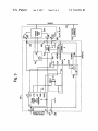
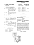
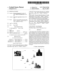
FIG. 1 is a block diagram of a simple netWork manage
ment protocol (SNMP) netWork embodiment of the present
Will be alerted to a probable Wiring error.
Many commercial netWork devices provide a contact or
logic-level input port that can be usurped for the “tickle”
invention;
signal. Cisco Systems routers, for example, provide an input
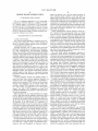
FIG. 2 is a ?owchart of a method of appliance poWer
sWitch status detection, according to the present invention;
25
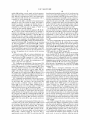
FIG. 3 is a schematic of a representative intelligent poWer
module such as are included in the netWork of FIG. 1;
FIG. 4 is a schematic diagram of the load sensor included
interrupt has been described here because it demands imme
diate system attention, but a polled input port could also be
used.
A netWork appliance 38, 40, 42, 44, that needs to have its
in the intelligent poWer module of FIG. 3; and
FIG. 5 is a schematic diagram of the poWer-on sensor
30
included in the intelligent poWer module of FIG. 3.
DETAILED DESCRIPTION OF THE
PREFERRED EMBODIMENTS
35
FIG. 1 illustrates a simple netWork management protocol
referred to herein by the general reference numeral 10. The
the appliance to reboot. In such instances, a “tickle” signal
from an IPM Would be ignored because the recipient is
essentially dead. Some systems may be temporarily aWak
ened from their death sleep by a non-maskable interrupt and
istrator needs to see. It Will therefore be best for routine
checks to be made before there is any trouble to register
SNMP netWork 10 includes a host 12 With a TCP/IP con
agents 22 and 24 at the remote nodes. The SNMP manager
20 may comprise a commercial product such as IBM NET
poWer cycled on/olf may need such action to clear a softWare
lockup that has occurred. A poWer-on reset is needed to get
interrupt service routine. There may be enough resources to
issue the message and identi?cation that the system admin
(SNMP) netWork embodiment of the present invention,
nection 14 to a plurality of point-of-presence (POP) nodes
represented by a pair of netWork equipment racks 16 and 18.
SNMP netWork management is provided by a SNMP man
ager 20 in communication With a respective pair of SNMP
that can be supported in softWare to issue the necessary
message and identi?er to the system administrator. A device
40
45
Which IPM 30, 32, 34, 36, matches Which netWork appliance
38, 40, 42, 44.
If the devices being supplied operating poWer by the
IPM’s 30, 32, 34, 36, are NT-servers, then an RS-232 serial
interface is present that can be used for the “tickle” signal.
In particular, the request-to-send (RTS) control line can be
VIEW/6000, HP OPENVIEW, POLYCENTER, SunNet
MANAGER, Cabletron SPECTRUM, etc.
An uninterruptable poWer supply (UPS) 26 provides
provided With a pulled-up dry-contact or open-collector
from the IPM’s 30, 32, 34, 36. A application program
operating poWer to a TCP/IP-addressable enterprise poWer
manager 28. It also poWers a plurality of intelligent poWer
modules (IPM’s) 30, 32, 34, 36 that are able to sWitch the
operating poWer on/olf to a corresponding netWork appli
ances 38, 40, 42, 44.
An SNMP agent 46 is private to the poWer manager 28.
It does not depend on the equipment rack 16 or any of its
report message and identity When the RTS is toggled.
interface (API) is then added to the NT-server to issue the
50
numeral 100. The method 100 comprises a step 102 applying
a series of alternating current (AC) voltage pulses to an
55
netWork appliances 38, 40, 42, 44. The poWer manager 28 is
connected to independently control each of the intelligent
poWer modules 30, 32, 34, 36. Such control includes being
60
netWork appliances 38, 40, 42, 44. Although FIG. 1 shoWs
an on/olf status indication for the appliance sWitch. Method
100 does not result in the tuming-on and the operation of the
appliance during steps 102 or 104, and is therefore unob
trusive.
FIG. 3 illustrates an intelligent poWer module 200, similar
an SNMP SET command 50 that issue from the host 12.
The poWer manager 28 and IPM’s 30, 32, 34, 36, are also
able to generate an interrupt signal to each corresponding
appliance With an on/olf sWitch that are synchronized to a
source of AC poWer. A step 104 senses the presence of any
series of AC current pulses that result if the appliance sWitch
is closed. A step 106 analyzes any AC current pulses
detected in step 104 to determine if they resulted from the
application of the AC voltage in step 102. A step 108 outputs
able to sense the poWer-on and load status of each of the
netWork appliances 38, 40, 42, 44 and to sWitch poWer on
and off to each of the netWork appliances 38, 40, 42, 44.
Such status is sensed and reported by an SNMP GET
command 48 and the poWer sWitching is accomplished With
FIG. 2 shoWs a method of appliance poWer sWitch status
detection, referred to herein by the general reference
65
to intelligent poWer modules 30, 32, 34, 36, Which may be
located external or internal to devices 38, 40, 42, 44, or
internal or external to the UPS 26. The intelligent poWer
US 7,162,521 B2
7
8
module 200 includes a power supply and clock generator
therefore gates through the seventy volt AC Waveform tWice
each cycle such that altemating pulses of +70 volts and —70
212, a load sensor 214, a poWer-on sensor 216, a solid-state
relay 218 and a microprocessor 220. A serial input/output
(l/O) connection 221 provides for communication With a
controller, e.g., poWer manager 28.
A “tickle” relay 222 is controlled by the microprocessor
220 and can issue a dry-contact test signal. Such signal is
volts are sent through sWitch 223 and load sensor 214. If a
current ?oWs because the sWitch 223 is closed, a character
istic pulse synchronized to the CLK signal Will appear as an
output from the opto-isolator 248. A resistor 250 provides a
pull-up to a current sense input to the microprocessor 220.
If the sWitch 223 is open, the characteristic pulses Will not
intended to stimulate a message and identity report to a
system administrator. Preferably, the operating poWer is
appear. An “on-sense” opto-isolator 252 provides isolation
controlled by an 1PM and such test signal or “tickle” are
Wired to the same netWork appliance.
for a voltage sense input to the microprocessor 220.
The microprocessor 220 analyZes and stores its determi
nation of Whether the poWer is applied to the device 38*44
and Whether the sWitch 223 is closed. Such data is thereafter
useful to control the relay 242. The microprocessor 220 is
programmed to control the relay 242 and to report the
An appliance, such as the netWork appliances 38, 40, 42,
44, has a poWer on/olf sWitch 223 that may be internal or
external to the appliance, and is represented in FIG. 3 by a
netWork device load 224 connected to a netWork 225. The
sWitch 223 may also actually comprise both internal and
external sWitches in series. The incoming alternating current
(AC) line poWer is applied to the intelligent poWer module
presence of current and voltage to the appliance through
serial communication conducted over the serial 1/ O connec
tion 221.
The poWer manager 28 is able to read from the intelligent
200 at a hot (H) terminal 226, a neutral (N) terminal 227 and
a ground (G) terminal 228. The appliance has its incoming
20
(N) terminal 238 and a ground (G) terminal 240. A relay 242
alloWs automatic remote control by the microprocessor of
poWer to the appliance due to its position in the incoming
25
AC line.
30
independent power-cycling of each and any of the network
appliances 38, 40, 42, 44. Such poWer cycling promotes a
35
the server program, the SNMP agent 22 and 24 on a remote
40
volt digital output (I_SENS) that indicates load/no-load to
the microprocessor 220. A resistor 250 provides a pull-up to
a current sense input to the microprocessor 220.
FIG. 5 represents an embodiment of the poWer-on sensor
216 included in FIG. 3. The poWer-on sensor 216 includes
45
an opto-isolator 252. The output of the opto-isolator 252
goes loW When a suf?cient voltage is dropped across a
resistor 254. A ?ve volt poWer supply connection and a
pull-up 256 provide a ?ve volt logic output (V_SENS) that
indicates poWer/no-poWer to the microprocessor 220.
poWer-up reset of the appliance, e.g., When the SNMP agent
22 has reported a failure of the POP node 16 to the SNMP
manager 20.
SNMP de?nes a client/server relationship. The client
program, netWork manager 20, makes virtual connections to
reference voltage provided by a poWer supply 246, the
output of the voltage comparator 245 goes high. A resistor
247 couples this to an opto-isolator 248 and produce a ?ve
in response to the SET command 50. Such SET commands
modify the MIB variable de?ned for poWer on/olf, and alloW
because sWitch 223 is closed, the microprocessor Will
receive a logic loW status indication.
FIG. 4 represents an embodiment of the load sensor 214
included in FIG. 3. The load sensor 214 comprises a sense
resistor 244 connected to a voltage comparator 245. When
the voltage dropped across the sense resistor 244 exceeds a
38, 40, 42, 44, and Whether such loads are turned on. The
poWer manager 28 and its SNMP agent 46 are able to report
such status in response to the GET command 48. The GET
command modi?es a MIB variable that is reported by the
SNMP agent 46 to the SNMP manager 20.
The poWer manager 28 is able to require the intelligent
poWer modules 30, 32, 34, 36, to turn the poWer being
supplied to the netWork appliances 38, 40, 42, 44, on or off
A netWork monitor 243 and a system administrator are
able to receive message and identity reports issued by the
netWork device load 224 in response to a “tickle” signal.
The load sensor 214 is such that if a current is ?oWing
poWer modules 30, 32, 34, 36, Whether there is a proper
operating voltage being supplied to the netWork appliances
AC line poWer applied to a hot (H) terminal 230, a neutral
(N) terminal 232 and a ground (G) terminal 234, Which are
respectively connected to a hot (H) terminal 236, a neutral
50
netWork device. The database controlled by the SNMP agent
is the management information base (MIB). The MIB is a
standard set of statistical and control values that provides
information about the attributes of devices attached to the
network. SNMP alloWs for the extension of these standard
values With values that are speci?c to a particular SNMP
agent through the use of private MlBs. The use of private
MIB variables alloWs SNMP agents to be modi?ed for a
variety of devices, e.g., bridges, hubs, routers and CSU/
DSUs, etc. SNMP operates by exchanging netWork infor
mation through protocol data unit (PDU) messages. PDUs
In operation, the device 200 senses if sWitch 223 is closed
or open by converting AC current pulses from the poWer
carry variables that have both titles and values. There are
?ve types of PDUs that SNMP uses to monitor a netWork,
supply 212 that How through the series circuit comprising
the solid-state relay 218, the H-ter'minals 230 and 236, the
sWitch 223, the netWork device load 224, the N-ter'minals
tWo for reading terminal data, tWo for setting terminal data,
and one, the trap, monitoring netWork events. Every SNMP
55
The poWer supply and clock generator 212 provides a ?ve
volt pulse clock (CLK) to the microprocessor 220 at each
Zero-crossing of the incoming AC poWer line voltage across
the H-terminal 226 and the N-terminal 227. A slightly
delayed version of the clock is output by the microprocessor
220 to control the solid-state relay 218. A seventy volt AC
output (70VAC) of the poWer supply and clock generator
message consists of a variable, and every variable consists
of a variable title, the integer, string data type of the variable,
232 and 238, the load sensor 214, and return to the poWer
supply 212. If the sWitch 223 is open, no such current can
How.
Whether the variable is read-only or read-Write, and the value
of the variable.
The SNMP manager 20 collects information via MlBs
60
about routers, hubs, bridges, concentrators, servers, sWitches
and other netWork appliances. When a problem at a remote
node is detected, the corresponding SNMP agent issues an
alarm that identi?es the problem by type and node address.
The SNMP manager typically sends a Telnet script to a
212 provides a reduced voltage AC sine Wave that is
TCP/lP-addressable enterprise poWer manager. The Telnet
script instructs the enterprises poWer manager to cycle the
approximately seventy volts RMS. The solid-state relay 218
poWer cycle, to recover an otherWise locked-up netWork
65
US 7,162,521 B2
10
device. SNMP management is not required for the enterprise
power manger and the associated intelligent power modules.
The intelligent power modules include normally closed
relays so power is always on except when the relay is
User interfaces are preferably provided to be con?gured
by a system administrator at the SNMP manager 20. A
screen interface allows an operator to control individual
intelligent power modules 30, 32, 34, 36, directly from an
associated keyboard. A command interface preferably
deliberately opened to trigger a power on reset and reboot.
The network management application monitors the UPS and
the network appliances.
allows script ?les to be constructed and sent directly for
execution. Response codes are returned after each command
is executed. Group names are preferably supported which
allows a single command to control multiple devices.
The power manager 28 preferably supports a variety of
communication interfaces, such as, RS-232 and ETHER
NET. Out-of-band communications are connectable through
The load sensor and power-on sensor can be combined
such that a console operator can determine if electrical
power is available to an equipment rack and to an individual
network appliance. A relay reset located between the power
source and the client equipment node supports an SNMP
type SET command that can be de?ned to open and close a
an RS-232 interface using a DB9-type connector on a back
relay to power-cycle the network appliance. Such power
panel. Such a port is used to establish communications
cycling can clear a lockup condition and allow the device to
return to normal operation via its own internal power-up
reset mechanism.
A console operator can be noti?ed by conventional means
that a router is failing. A determination then needs to be
sessions. An external dial-in-modem can also be used to
establish communications. In-band communications are
made that the electrical power is available to the equipment
rack and to an individual network appliance. The next action
would be to try to power-cycle an individual network
appliance to return it to operational status.
Apower-on sensor 216, a load sensor 214 and a relay reset
218 can be combined in the electrical power supply con
nected to the equipment rack. Once a console operator has
determined both that the router is failing and that the
electrical power is available to the equipment rack and to the
individual network appliance, the next logical step can be to
power-cycle the individual network appliance, e.g., to return
it to operational status.
preferably provided with a LAN communications interface
that supports ETHERNET connections, e.g., 10BaseT or
10Base2, with both IPX and TCP/IP protocols being sup
20
ported.
A seven layer network communications model that is
universally used to communicate between most types of
computer networks is de?ned by the International Organi
Zation of Standards (ISO). Every layer relies on all its lower
25
layers to complete its communication tasks. There are seven
layers identi?ed as the application, presentation, session,
transport, network, data link, and physical layers. For
30
example, e-mail is a task of the application layer. The
application layer uses all of the layers below it to deliver
particular e-mail messages to their destinations. The presen
tation layer formats the look of the e-mail, and the physical
Where the in-place equipment that supplies electrical
layer actually transports the binary data across the network.
power for an equipment rack cannot be modi?ed to incor
For more information, see, Naugle, Matthew G., Local Area
porate the functions of an intelligent power module, the
intelligent power module 200 can be connected in-line
between the electrical power source and the equipment
Networking, (McGraw-Hill: New York), 1991.
35
power receptacle. The intelligent power module provides the
The information that the SNMP manager 20 can gather
from the SNMP agents 22 and 24 around a network is the
de?nition of the MIB and it has a hierarchical tree structure.
At the top of the tree is the general network information.
necessary power-on sensor, load sensor, and relay reset
circuit functions. The network management console opera
Each branch of the tree gets more detailed about a speci?c
tor can determine by conventional means that a device such 40 network area. The leaves of the tree include the most detail.
as a router is failing. With the present invention it can be
A device may be a parent in the tree, and its children can be
discrete serial and parallel devices. Each node in the MIB
further determined that electrical power is available to an
equipment rack and to an individual network appliance, and
tree can be represented by a variable. The top of a local area
network MIB tree is usually referred to as “internet”.
even that the device’s power switch is on. The present
invention further permits an action to power-cycle the indi
vidual network appliance, to return it to operational status by
forcing a reboot.
45
A pass-through communication switch is preferably
included with power manager 28 that is installed in the same
equipment rack with other network appliances because
50
many network appliances have RS-232 network manage
ment system ports. Such management ports are intended to
permit users to upload new software and to update and
and have both titles and values. SNMP uses ?ve types of
PDUs to monitor a network. Two deal with reading terminal
inspect con?guration tables. A call-pass-through multi-port
communications switch allows the initial communications
Managed objects are accessed via the MIB and are
de?ned using a subset of ASN.1. Each object type is named
by an object identi?er, which is an administratively assigned
name. The object type and an object instance uniquely
identify a speci?c object. Descriptor text strings are used to
refer to the object type.
Network information is exchanged with protocol data unit
(PDU) messages, which are objects that contain variables
55
data, two deal with setting terminal data, and one, the trap,
is used for monitoring network events such as terminal
session with modern RS-232 or TCP/IP to be switched
directly to a device’s management port. For example, when
start-ups or shut-downs. When a user wants to see if a
a communications session is established to reboot a locked
terminal is attached to the network, for example, SNMP is
up router, after the router is back in operation, the same
communications session can be transferred from the power
60
manager 28 to the router’s management port. Preferably,
such transfer of the particular communications session can
the terminal is attached”. If the terminal was shut o?‘, the
user would receive a packet informing them of the shutdown
with a trap PDU.
be switched directly from a user interface screen in com
munication with the SNMP agent 46. The network operator
can thereafter continue the repair operation by inspecting or
used to send out a read PDU to that terminal. If the terminal
is attached, the user receives back a PDU with a value “yes,
updating the router’s con?guration table, and to verify its
In alternative embodiments of the present invention, it
may be advantageous to include the power manager and
intelligent power module functions internally as intrinsic
operability.
components of an uninterruptable power supply (UPS). In
65
US 7,162,521 B2
11
12
applications Where it is too late to incorporate such func
tionally, external plug-in assemblies are preferred such that
Wherein said microprocessor is adapted to communicate the
olf-the-shelf UPS systems can be used.
load status to the netWork poWer manager application
6. The netWork poWer manager apparatus of claim 5
Although the present invention has been described in
through the poWer manager agent application as a variable
terms of the present embodiment, it is to be understood that 5 in a managed information base (MIB) data construct com
the disclosure is not to be interpreted as limiting. Various
alterations and modi?cations Will no doubt become apparent
to those skilled in the art after having read the above
municated over the netWork communications connection in
accordance With a prede?ned simple netWork management
protocol (SNMP).
disclosure. Accordingly, it is intended that the appended
7. The netWork poWer manager apparatus of claim 1
claims be interpreted as covering all alterations and modi 10 Wherein said poWer on/olf device comprises a relay.
?cations as fall Within the true spirit and scope of the
invention.
What is claimed is:
1. A netWork poWer manager apparatus of the type useable
in a computer netWork having a host system With a netWork
poWer manager application adapted to issue netWork com
8. The netWork poWer manager apparatus of claim 7
Wherein said microprocessor controls the poWer applied to
the corresponding poWer outlet in response to a variable in
a managed information base (MIB) data construct commu
nicated from the netWork poWer manager application to the
poWer manager agent application over the netWork commu
mands and communicate netWork commands over a netWork
nications connection in accordance With a prede?ned simple
communications connect supporting IP communications, the
netWork poWer manager apparatus comprising in combina
netWork management protocol (SNMP).
tion:
a poWer supply housing;
a poWer manager agent application mounted in the poWer
supply housing and being connectable to the netWork
communications connection;
a plurality of poWer outlets mounted in the poWer supply
9. The netWork poWer manager apparatus of claim 1
20 Wherein each intelligent poWer module further comprises:
a microprocessor in communication With:
a poWer state sensor that independently senses the
poWer-on status of the corresponding poWer outlet;
25
a load sensor that independently senses the load status
of the corresponding poWer outlet; and
a relay that independently controls the poWer applied to
the corresponding poWer outlet.
10. The netWork poWer manager apparatus of claim 1
in IP communication With said netWork poWer manager 30 Wherein each intelligent poWer module further comprises:
housing; and
a plurality of intelligent poWer modules (lPMs) mounted
in the poWer supply housing and connectable to said
netWork communications connection and thereby being
a poWer supply and clock generator, connected to a
load-sensor, a poWer state sensor, and a relay and that
application through said poWer manager agent appli
cation, each said intelligent poWer module being
adapted to provide poWer from a poWer source to a
applies a series of alternating current (AC) voltage
corresponding poWer outlet among the plurality of
poWer outlets and being in communication With said
poWer manager agent application to provide poWer
cycling on-olf of said corresponding poWer outlet and
pulses synchroniZed to a source of AC poWer to the
35
corresponding poWer outlet With an on/olf sWitch, said
load sensor being adapted to sense the presence of a
series of AC current pulses that result if said on/olf
sWitch is closed;
a microprocessor that analyZes any AC current pulses
at least one of poWer state sensing and load-sensing
With respect to said corresponding poWer outlet in
response to one or more commands, Wherein each 40
detected by said load sensor to determine if they
intelligent poWer module comprises a microprocessor
resulted from application of the AC voltage pulses; and
connected by a poWer on/olf device to independently
control the poWer applied to said corresponding poWer
outlet, and Wherein said microprocessor is also con
nected by at least one among a voltage sensing device
an input/output connection connected to said micropro
cessor that outputs an on/olf status indication for said
45
to independently sense the poWer state of said corre
Wherein each intelligent poWer module further comprises:
sponding poWer outlet and a load sensing device to
independently sense the load status of said correspond
poWer output terminals With a poWer sWitch;
a synchroniZed pulse generator connected to said termi
ing poWer outlet.
2. The netWork poWer manager apparatus of claim 1
further comprising a serial communications connection sup
nals that applies an alternating pulsed voltage synchro
50
niZed to an incoming alternating current poWer source
to the corresponding poWer outlet;
ported by a microprocessor, said serial communications
connection connecting each of the intelligent poWer modules
to the poWer manager agent application.
3. The netWork poWer manager apparatus of claim 1
sWitch.
11. The netWork poWer manager apparatus of claim 1
a load sensor connected in series With said terminals and
said poWer supply/clock generator; and
55
a microprocessor connected to both said synchroniZed
Wherein said voltage sensing device comprises an opto
pulse generator and the load sensor, said microproces
isolator.
4. The netWork poWer manager apparatus of claim 3
Wherein said microprocessor communicates the poWer-on
status of the lPM-corresponding poWer outlet to the netWork
sor being adapted to determine if a current sensed by
said load sensor resulted from both said sWitch being
60
12. The netWork poWer manager apparatus of claim 11
Wherein said poWer state sensor comprises a voltage state
determination processor in voltage determination commu
nication With a poWer relay in poWer controlling commu
poWer manager application through said poWer manager
agent application as a variable in a managed information
base data construct communicated over the netWork com
munications connection in accordance With a prede?ned
simple netWork management protocol.
5. The netWork poWer manager apparatus of claim 1
Wherein said load sensing device comprises a load sensor.
closed and application of the alternating pulsed voltage
from said synchroniZed pulse generator.
65
nication With said corresponding poWer outlet.
13. The netWork poWer manager apparatus of claim 11
Wherein said synchroniZed pulse generator further com
US 7,162,521 B2
13
14
prises a clock generator With an output that coincides With
a managed information base (MIB) data construct commu
nicated from the netWork poWer manager application to the
poWer manager agent application over the netWork commu
each zero-crossing of the incoming alternating current
poWer.
14. The netWork poWer manager apparatus of claim 11
Wherein said load sensor further comprises an opto-isolator
nications connection in accordance With a prede?ned simple
netWork management protocol (SNMP).
15. The netWork poWer manager apparatus of claim 14
24. The netWork poWer manager apparatus of claim 16
Wherein said microprocessor is in communication With:
Wherein said microprocessor further comprises a data input
a poWer on sensor that independently senses the poWer-on
and a sense resistor.
status of the corresponding poWer outlet;
connected to said opto-isolator and a data output connected
to control the synchronized pulse generator.
a load sensor that independently senses the load status of
the corresponding poWer outlet; and
16. A netWork poWer manger apparatus of the type
a relay that independently controls the poWer applied to
the corresponding poWer outlet.
25. The netWork poWer manager apparatus of claim 16
Wherein each intelligent poWer module further comprises: a
poWer supply and clock generator connected to a load
useable in a computer netWork having a host system With a
netWork poWer manager application adapted to issue net
Work commands and communicate netWork commands over
a netWork communications connection, the netWork poWer
manger apparatus comprising in combination:
a poWer manager agent application connectable to the
sensor, a poWer on sensor, and a relay, said poWer supply and
netWork communications connection;
a plurality of poWer outlets; and
a plurality of intelligent poWer modules (lPMs) connect
clock generator applying a series of alternating current (AC)
20
able in communication With said netWork poWer man
ager application, each said intelligent poWer module
comprising a microprocessor, and each said intelligent
poWer module being adapted to provide poWer from a
poWer source to a corresponding poWer outlet among
microprocessor analyzes any AC current pulses detected by
said load sensor to determine if they resulted from applica
25
the plurality of poWer outlets and being in communi
cation With said poWer manager agent application to
poWer outlet and at least one of poWer-on sensing and
30
Wherein each intelligent poWer module further comprises:
poWer output terminals With a poWer sWitch;
outlet in response to one or more commands.
a synchronized pulse generator connected to said termi
17. The network poWer manager apparatus of claim 16
further comprising a serial communications connection sup
nals that applies an alternating pulsed voltage synchro
ported by said microprocessor, said serial communications
connection being adapted to connect each of the intelligent
tion of the AC voltage pulses; and each intelligent poWer
module further comprises an input/output connection con
nected to said microprocessor that outputs an on/olf status
indication for said sWitch.
26. The netWork poWer manager apparatus of claim 16
provide poWer cycling on-olf of said corresponding
load-sensing With respect to said corresponding poWer
voltage pulses synchronized to a source of AC poWer to the
corresponding poWer outlet With an on/olf sWitch, said load
sensor being adapted to sense the presence of a series of AC
current pulses that result if said on/olf sWitch is closed; said
nized to an incoming alternating current poWer source
35
to the corresponding poWer outlet; and
poWer modules to the netWork poWer manager application.
18. The netWork poWer manager apparatus of claim 16
a load sensor connected in series With said terminals and
Wherein said microprocessor is connected by an opto-isola
tor Whereby the intelligent poWer module may indepen
Wherein said microprocessor is connected to both said
said poWer supply/clock generator; and
dently sense the poWer-on status of said corresponding
poWer outlet.
19. The netWork poWer manager apparatus of claim 18
Wherein said microprocessor communicates the poWer-on
status of the lPM-corresponding poWer outlet to the netWork
40
poWer manager application through said poWer manager
45
sWitch being closed and application of the alternating
pulsed voltage from said synchronized pulse generator.
agent application as a variable in a managed information
base data construct communicated over the netWork com
munications connection in accordance With a prede?ned
simple netWork management protocol.
20. The netWork poWer manager apparatus of claim 16
Wherein said microprocessor is connected by a load sensor
that independently senses the load status of the correspond
50
55
nication With said corresponding poWer poWer outlet.
28. The netWork poWer manager apparatus of claim 26
Wherein said synchronized pulse generator further com
prises a clock generator With an output that coincides With
poWer.
29. The netWork poWer manager apparatus of claim 26
Wherein said load sensor further comprises an opto-isolator
and a sense resistor.
30. The netWork poWer manager apparatus of claim 29
poWer manager agent application as a variable in a managed
information base (MIB) data construct communicated over
the netWork communications connection in accordance With
a prede?ned simple netWork management protocol (SNMP).
27. The netWork poWer manager apparatus of claim 26
Wherein said poWer state sensor comprises a voltage state
determination processor in voltage determination commu
nication With a poWer relay in poWer controlling commu
each zero-crossing of the incoming alternating current
ing poWer outlet.
21. The netWork poWer manager apparatus of claim 20
Wherein: said microprocessor communicates the load status
to the netWork poWer manager application through the
synchronized pulse generator and the load sensor, said
microprocessor being adapted to determine if a current
sensed by said load sensor resulted form both said
Wherein said microprocessor further comprises a data input
connected to said opto-isolator and a data output connected
60
to control the synchronized pulse generator.
31. A netWork poWer manager apparatus of the type
22. The netWork poWer manager apparatus of claim 16
Wherein said microprocessor is in communication With a
useable in a computer netWork having a host system With a
relay that independently controls the poWer applied to the
corresponding poWer outlet.
netWork poWer manager application adapted to issue net
Wherein said microprocessor controls the poWer applied to
Work commands and communicate netWork commands over
a netWork communications connection supporting 1P com
munications, the netWork poWer manager apparatus com
the corresponding poWer outlet in response to a variable in
prising in combination:
23. The netWork poWer manager apparatus of claim 22
65
US 7,162,521 B2
15
16
a power manager agent application mounted in the hous
processor in voltage determination communication
With a poWer relay in poWer controlling communication
ing and being connectable to the network communica
With said corresponding poWer outlet, said intelligent
tions connection;
poWer module being in poWer state reporting commu
nication With the netWork poWer manager application
a power supply housing;
a plurality of poWer outlets mounted in the poWer supply
housing; and
through said poWer manager agent application through
a plurality of intelligent poWer modules mounted in the
poWer supply housing and connectable to said netWork
one or more variables in a managed information base
data construct communicated over the netWork com
communications connection and thereby being in IP
munications connection in accordance With a pre
communication With said netWork poWer manager
de?ned simple netWork management protocol.
application through said poWer manager agent appli
32. The netWork poWer manager apparatus of claim 31 in
Which the voltage state determination processor comprises a
cation, each intelligent poWer module comprising a
microprocessor, and each said intelligent poWer mod
ule being adapted to provide poWer from a poWer
microprocessor portion controllably communicating With
said poWer relay.
source to a corresponding poWer outlet among the
33. The netWork poWer manager apparatus of claim 32 in
Which the netWork communications connection is a serial
plurality of poWer outlets and being in communication
With said poWer manager agent application to provide
poWer cycling on-olT of said corresponding poWer
connection providing serial communication betWeen the
netWork poWer manager application and the poWer manager
outlet and at least one of poWer state sensing and
load-sensing With respect to said corresponding poWer
outlet in response to one or more commands, said
poWer state sensor having a voltage state determination
20
agent application.
UNITED STATES PATENT AND TRADEMARK OFFICE
CERTIFICATE OF CORRECTION
PATENT NO.
: 7,162,521 B2
Page 1 of 1
APPLICATION NO. : 10/806130
DATED
INVENTOR(S)
: January 9, 2007
: Ewing et al.
It is certified that error appears in the above-identi?ed patent and that said Letters Patent is
hereby corrected as shown below:
Column 1, lines 10-12, “now US. Patent No. 5,949,974 the contents of which are
hereby incorporated by reference in its entirety” should be replaced by --now US.
Patent No. 5,949,974. The contents of US. Patent No. 7,010,589 and US. Patent No.
5,949,974 are hereby incorporated by reference--.
Column 1, line 50, “browser win dow” should be --browser window--.
Column 3, line 33, “speci?c to device lasses” should be --specific to device classes--.
Column 7, line 40, “and produce” should be --and produces--.
Column 14, line 41, “resulted form both” should be --resulted from both--.
Column 14, line 48, “corresponding power power outlet” should be --corresponding
power outlet--.
Signed and Sealed this
Thirty-?rst Day of July, 2007
m W451i,”
JON W. DUDAS
Director ofthe United States Patent and Trademark O?ice