1
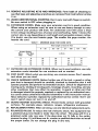
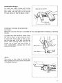
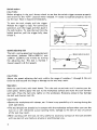
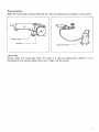
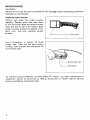
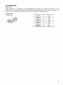
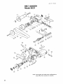
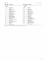
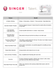
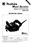
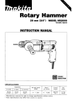
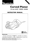
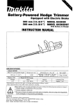
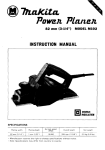
Belt Sander
MODEL 9031
INSTRUCTION MANUAL
S PEClFICAT10 NS
Belt size
30 mm x 533 mm
(1.3116" x 21")
Overall length
Net weight
380 mm (14-31/32")
2.1 kg (4.6 Ibs)
Belt speed
200 m - 1,000 m
(656 ft.
3,280 f t , ) / m ~ n .
~
* Manufacturer reserves the right t o change specifications without notice.
* Note: Specifications may differ from country t o country.
WARNING: For your personal safety, READ and UNDERSTAND before using.
SAVE THESE INSTRUCTIONS FOR FUTURE REFERENCE.
IMPORTANT
SAFETY INSTRUCTIONS
(For All Tools)
WARNING: WHEN USING ELECTRIC TOOLS, BASIC SAFETY
PRECAUTIONS SHOULD ALWAYS BE FOLLOWED TO REDUCE
THE RISK OF FIRE, ELECTRIC SHOCK, AND PERSONAL
INJURY, INCLUDING THE FOLLOWING:
READ ALL INSTRUCTIONS.
1. KEEP WORK AREA CLEAN. Cluttered areas and benches invite injuries.
2. CONSIDER WORK AREA ENVIRONMENT. Don't use power tools in damp
or wet locations. Keep work area well lit. Don't expose power tools t o rain.
Don't use tool in presence of flammable liquids or gases.
3. KEEP CHILDREN AWAY. All visitors should be kept away from work area.
Don't let visitors contact tool or extension cord.
4. STORE IDLE TOOLS. When not in use, tools should be stored in dry, and high
or locked-up place - out of reach of children.
5. DON'T FORCE TOOL. It will do the job better and safer at the rate for which
it was intended.
6. USE RIGHT TOOL. Don't force small tool or attachment t o do the job of a
heavy-duty tool. Don't use tool for purpose not intended; for example, don't
use circular saw for cutting tree limbs or logs.
7. DRESS PROPERLY. Don't wear loose clothing or jewelry. They can be caught
in moving parts. Rubber gloves and non-skid footwear are recommended
when working outdoors. Wear protective hair covering t o contain long hair.
8. USE SAFETY GLASSES. Also use face or dust mask if cutting operation is
dusty.
9. DON'T ABUSE CORD. Never carry tool by cord or yank it to disconnect from
receptacle. Keep cord from heat, oil, and sharp edges.
IO. SECURE WORK. Use clamps or a vise to hold work. It's safer than using
your hand and it frees both hands t o operate tool.
11. DON'T OVERREACH. Keep proper footing and balance at all times.
12. MAINTAIN TOOLS WITH CARE. Keep tools sharp and clean for better and
safer performance. Follow instructions for lubricating and changing accessories. Inspect tool cords periodically and if damaged, have repaired by authorized service facility. Inspect extension cords periodically and replace if
damaged. Keep handles dry, clean, and free from oil and grease.
13. DISCONNECT TOOLS. When not in use, before servicing, and when changing accessories, such as blades, bits, cutters.
14. REMOVE ADJUSTING KEYS AND WRENCHES. Form habit of checking to
see that keys and adjusting wrenches are removed from tool before turning
it on.
15. AVOID UNINTENTIONAL STARTING. Don't carry tool with finger on switch.
Be sure switch is OFF when plugging in.
16. EXTENSION CORDS. Make sure your extension cord is in good condition.
When using an extension cord, be sure to use one heavy enough to carry
the current your product will draw. An undersized cord will cause a drop
in line voltage resulting in loss of power and overheating. Table 1 shows the
correct size to use depending on cord length and nameplate ampere rating.
If in doubt, use the next heavier gage. The smaller the gage number, the
heavier the cord.
TABLE 1
I
I
MINIMUM GAGE FOR CORD SETS
Total Length of Cord in Feet
0-25
I
26 - 50
Ampere Rating
More
Not More
Than
Than
0
-
6
-
10
12
~
-
6
10
12
16
I
51 - 100
I
101 - 150
A W G
18
18
16
14
16
16
16
12
;:
1
14
12
14
12
Not Recommended
17. OUTDOOR USE EXTENSION CORDS. When tool is used outdoors, use only
extension cords intended for use outdoors and so marked.
18. STAY ALERT. Watch what you are doing, use common sense. Don't operate
tool when you are tired.
19. CHECK DAMAGED PARTS. Before further use of the tool, a guard or other
part that is damaged should be carefully checked to determine that it will
operate properly and perform its intended function. Check for alignment of
moving parts, binding of moving parts, breakage of parts, mounting, and any
other conditions that may affect its operation. A guard or other part that
is damaged should be properly repaired or replaced by an authorized service center unless otherwise indicated elsewhere in this instruction manual.
Have defective switches replaced by authorized service center. Don't use
tool if switch does not turn it on and off.
20. GUARD AGAINST ELECTRIC SHOCK. Prevent body contact with grounded
surfaces. For example; pipes, radiators, ranges, refrigerator enclosures.
21. REPLACEMENT PARTS. When servicing, use only identical replacement parts.
22. POLARIZED PLUGS. To reduce the risk of electric shock, this equipment has
a polarized plug (one blade is wider than the other). This plug will fit in a
polarized outlet only one way. If the plug does not fit fully in the outlet,
reverse the plug. If it still does not fit, contact a qualified electrician to install
the proper outlet. Do not change the plug in any way.
3
VOLTAGE WARNING: Before connecting the tool to a power source (receptacle,
outlet, etc.) be sure the voltage supplied is the same as that specified on the
nameplate of the tool. A power source with voltage greater than that specified
for the tool can result in SERIOUS INJURY t o the user - as well as damage t o
the tool. If in doubt, DO NOT PLUG IN THE TOOL. Using a power source with
voltage less than the nameplate rating is harmful t o the motor.
ADDITIONAL SAFETY RULES
1. Hold the tool firmly with both hands.
2. Make sure the belt is not contacting the workpiece before the switch is turned
on.
3.Keep hands away from rotating parts.
4. Do not leave the tool running. Operate the tool only when hand-held.
5. This tool has not been waterproofed, so do not use water on the workpiece
surface.
SAVE THESE INSTRUCTIONS.
4
Installing the side grip
For your own safety, always use the side
grip. Install it by screwing it firmly on the
grip holder. The side grip can be pivoted
for easy operation. See the figure a t right.
Side grip can pivoted
-
Side grip
Grip holder
Installing or removing the abrasive belt
CAUTION :
Always be sure that the tool is switched off and unplugged before installing or removing
the belt.
Loop the belt over the front pulley. Hold
the tool as shown a t right and press down
to retract the front pulley so that you can
slip the other end of the belt over the rear
pulley. When pressing down the tool, be
careful not to allow the front pulley to
turn unexpectedly, causing you to lose
control of the tool.
NOTE :
The arrow on the inside of the belt and
that marked on the rear pulley must point
in the same direction.
Arrow
-,
5
Switch action
CAUTION :
Before plugging in the tool, always check t o see that the switch trigger actuates properly
and returns to the "OFF" position when released. If i t does not operate properly, do not
use the tool. Have it repaired immediately.
To start the tool, simply pull the trigger.
Release the trigger to stop. For continuous
operation, pull the trigger and then push in
the lock button. To stop the tool from the
locked position, pull the trigger fully, then
release it.
Lock button
Speed adjusting dial
The belt running speed can be adjusted and
maintained between 200 m (656 ft.) and
1,000 m (3,280 ft.) per minute by turning
the adjusting dial. The dial is marked 1
(lowest speed) t o 6 (full speed).
Speed adjusting dial
I
CAUTION :
Adjust the speed adjusting dial only within the range of numbers 1 through 6.
force the dial beyond this range or damage t o the tool may result.
Do
not
Operation
Hold the tool firmly with both hands. Turn the tool on and wait until it attains your desired speed. Gently apply the tool to the workpiece surface and move the tool forward
and back. Press the belt only lightly on the workpiece. Excessive pressure may damage
the belt and shorten tool life.
CAUTION :
0 Secure the workpiece with clamps, etc. if there i s any possibility of it moving during the
work operations.
0
0
6
The tool should not already be in contact with the workpiece surface when you turn the
tool on or off, Otherwise a poor sanding finish, damage to the belt of loss of control
of the tool may result.
When working with the tool, be very careful to avoid any contact of the tool and belt
with any part of your body or anyone or anything near you.
Dust extraction
Open the nozzle cap. Connect the hose of a vacuum cleaner/dust collector to the nozzle.
Nozzle
cap
Vacuum cleaner
CAUTION :
Always close the nozzle cap when the hose of a vacuum cleaner/dust collector i s not
connected to the nozzle. Never insert your finger into the nozzle.
7
MAINTENANCE
CAUTION :
Always be sure that the tool i s switched off and unplugged before attempting t o perform
inspection or maintenance.
Replacing carbon brushes
Remove and check the carbon brushes
regularly. Replace when they wear down
to the limit mark. Keep the carbon brushes
clean and free t o slip in the holders. Both
carbon brushes should be replaced a t the
same time. Use only identical carbon
brushes.
3
Limit mark
Use a screwdriver to remove the brush
holder caps. Take out the worn carbon
brushes, insert the new ones and secure the
brush holder caps.
I
\
Brush holder cap
LScrewdriver
'To maintain product SAFETY and RELIABILITY, repairs, nay other maintenance or
adjustment should be performed by Makita Authorized or Factory Service Centers,
always using Makita replacement parts.
8
ACCESSORIES
CAUTION :
These accessories or attachments are recommended for use with your Makita tool specified in this
manual. The use of any other accessories or attachments might present a risk of injury t o persons. The
accessories or attachments should be used only in the proper and intended manner.
0
Abrasive belt
(10 per pkg)
Part No.
742301.7
Grit
I
40
60
742302-5
742303-3
80
742304- 1
100
742305-9
742334-2
I
I
120
150
9
June-01 -'95
US
BELT SANDER
Model 9031
Note: The switch and other part configurations
may differ from country to country.
10
MODEL 9031
June-01-'95
$zD
ED
MO" : '
DESCRIPTION
3
4
5
6
7
8
1
1
1
1
3
10
11
12
13
14
15
16
17
18
19
20
21
22
1
1
1
1
1
1
1
1
1
1
1
2
1
1
1
1
1
23
3
24
25
27
28
1
1
1
2
9
-
DESCRIPTION
MACHINE
MACHINE
1
2
US
~
Grip 36
Hex Bolt Max40
Cap 30
Spring Pin 4 - 2 0
Tapping Screw 4x25
Flat Shoe
Tapping Screw Bind CT 5x12
Compression Spring 13
Flat Washer 12
Wmg Nut M 1 6
Gear Housing Complete
Ball Bearing 607L8
Helical Gear 35
s p m g P,n 3 5 - 12
Ball Rearing 69040DW
Bearing Retainer 4 4
Tapping Screw CT 4x12
Pulley 3 3 - 6 4
Abrasive Belt 30x533 AAlOO
Pulley h e r
Flaf Washer 5
Hex Socket Head Bolt M5xZO
Tapping Screw 4x18
Handle Cover
Switch
ContlDllel
Tapeina Screw 4x18
29
30
31
32
33
34
35
36
37
38
40
41
42
43
44
45
46
47
48
49
50
51
1
1
1
1
1
1
1
1
1
1
1
2
1
1
2
2
1
1
2
1
1
1
1
52
53
1
1
39
Strain Relief
Cord
Cord Guard
Sprmg PI" 4 20
Top Pulley Shaft
Pulley 3 0 - 2 5
Ball Bearing 6880DW
Sleeve 12
Ball Bearing 6880OW
Angle Stay Complete
Arm Complete
Wave Washer 12
Hex Nut M 6 - 1 7
Name Plate
Carbon Brush
Brush Holder Cap
Motor Housing Complete
FIELD ASSEMBLY
Tapping Screw Bind ET 4x60
Baffle Plate
Ball Bearing 627LB
Insulation Washer
ARMATURE ASSEMBLY
IWith Item 49 5 0 52 & 531
Fan 60
Ball Bearing 808DDW
- -
Note The s w i t c h and other part Specifications may dlffer f r o m country t o country
11
MAKITA LIMITED ONE YEAR WARRANTY
Warranty Policy
Every Makita tool is thoroughly inspected and tested before leaving the factory. It is warranted to
be free of defects from workmanship and materials for the period of ONE YEAR from the date of
original purchase. Should any trouble develop during this one- year period, return the COMPLETE
tool, freight prepaid, to one of Makita’s Factory or Authorized Service Centers. If inspection shows
the trouble is caused by defective workmanship or material, Makita will repair (or at our option,
replace) without charge.
This Warranty does not apply where:
repairs have been made or attempted by others:
repairs are required because of normal wear and tear:
The tool has been abused, misused or improperly maintained;
alterations have been made t o the tool.
IN NO EVENT SHALL MAKITA BE LIABLE FOR ANY INDIRECT, INCIDENTAL OR CONSEQUENTIAL DAMAGES FROM THE SALE OR USE O F THE PRODUCT. THIS DISCLAIMER
APPLIES BOTH DURING AND AFTER THE TERM O F THIS WARRANTY.
MAKITA DISCLAIMS LIABILITY FOR ANY IMPLIED WARRANTIES, INCLUDING IMPLIED
WARRANTIES O F “MERCHANTABILITY” AND “FITNESS FOR A SPECIFIC PURPOSE.’’
AFTER THE ONE-YEAR TERM O F THIS WARRANTY.
This Warranty gives you specific legal rights, and you may also have other rights which vary from
state to state. Some states do not allow the exclusion or limitation of incidental or consequential
damages, so the above limitation or exclusion may not apply t o you. Some states do not allow
limitation o n how long an implied warranty lasts, so the above limitation may not apply t o you.
Makita Corporation
3-11-8, Sumiyoshi-cho,
Anjo, Aichi 446 Japan
883891 - 064
PRINTED IN JAPAN
1995 - 7 - N