1
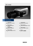
LTC 0440
Installation Manual
EN Digital Color Cameras
Installatiehandleiding
NL Digitale Kleurencamera
Manuel d’installation
FR Caméra Numérique
Couleur
Manuale d’installazione
IT
Installationsanleitung
DE Digitale Farbkamera
Manual de Instruções
PT Câmara Digital Colorida
Manual de instalación
ES Cámara Digitale de Color
Videocamera Digitale a Colori
ZH
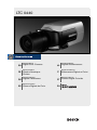
LTC 0440 | Installation Manual
EN | 1
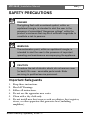
SAFETY PRECAUTIONS
EN
DANGER
The lighting flash with arrowhead symbol, within an
equilateral triangle, is intended to alert the user to the
presence of uninsulated "dangerous voltage" within the
product's enclosure that may be of sufficient magnitude to
constitute a risk to persons.
Installation
ENGLISH
Manual
WARNING
The exclamation point, within an equilateral triangle, is
intended to alert the user to the presence of important
operating and maintenance accompanying the appliance.
CAUTION
To reduce the risk of electric shock, do not remove cover
(or back). No user - servicable parts inside. Refer
servicing to qualified service personnel.
Important Safeguards
1.
2.
3.
4.
5.
6.
Keep these instructions.
Heed all Warnings.
Follow all instructions.
Do not use the apparatus near water.
Clean with a dry cloth only.
Do not install near heat sources such as radiators, heat registers,
stoves, or other apparatus that generates heat (including
amplifiers).
Bosch Security Systems | 2004-11
LTC 0440 | Installation Manual
7.
8.
9.
10.
11.
12.
13.
EN | 2
Do not defeat the purpose of a polarized or grounded mains plug.
A polarized plug has dissimilar prongs (one wider than the other)
to ensure correct polarity, while a grounded plug has an
additional 'ground' prong provided for your safety. If the plug
supplied with the apparatus does not fit into your outlet, consult
an electrician for advice.
Protect the power-supply cord from being walked on or pinched,
particularly close to plugs, receptacles and the point where it exits
from the apparatus.
Only use attachments and accessories (including stands, tripods,
mounting brackets and housings) specified or recommended by
the manufacturer.
Unplug the apparatus during lightning storms and when unused
for extended periods.
Do not attempt to service this unit yourself as opening or
removing covers may expose you to dangerous voltage or other
hazards. Refer all servicing to qualified service personnel.
Servicing is required when the apparatus does not function in the
normal way, has been dropped, if liquid has been spilled on it, or
if it has been exposed to rain or water. Unplug the unit from the
outlet and refer servicing to qualified service personnel.
An all-pole mains switch with contact separation of at least 3 mm
in each pole shall be incorporated in the electrical installation of
the building.
EN
WARNING
To reduce the risk of fire or electric shock, do not expose
this apparatus to rain or moisture.
Bosch Security Systems | 2004-11
LTC 0440 | Installation Manual
EN | 3
FCC INFORMATION
CAUTION
Any changes or modifications to construction of this
device that are not expressly approved by the party
responsible for compliance could void the userfs authority
to operate the equipment.
This equipment has been tested and found to comply with the limits
for a Class B digital device, pursuant to part 15 of the FCC Rules.
These limits are designed to provide reasonable protection against
harmful interference in a residential installation. This equipment
generates, uses and can radiate radio frequency energy and, if not
installed and used in accordance with the instructions, may cause
harmful interference to radio communications. However, there is no
guarantee that interference to radio or television reception, which can
be determined by turning the equipment off and on, the user is
encouraged to try to correct the interference by one or more of the
following measures:
• Re-orient or relocate the receiving antenna.
• Increase the separation between the equipment and receiver.
• Connect the equipment into an outlet on a circuit different from
that to which the receiver is connected.
• Consult the dealer or an experienced radio/TV technician for
help.
Bosch Security Systems | 2004-11
LTC 0440 | Installation Manual
EN | 4
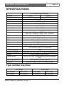
SPECIFICATIONS
LTC 0440/x0 High resolution
Standard
Active pixels (H x V)
PAL
NTSC
752 x 582
768 x 494
Imager
1/3" interline CCD
Resolution
480 TV lines
Minimum illumination
<0.4 lux (30 IRE)
Signal-to-noise ratio
> 50 dB
Video output
1 Vpp, 75Ω
Synchronization
Internal or Line-Lock (selectable)
Shutter
Auto / Flickerless / Off (selectable)
PAL: 1/50 - 1/125000 - NTSC: 1/60 - 1/150000
AGC
On (0-21 dB)/ Off (0 dB) (selectable)
BLC
On / Off (selectable)
ATW
Auto 2500 to 9000 K (with 'Hold' mode)
Lens mount
C and CS compatible
ALC
Video-iris or DC-iris (auto detect)
Power supply
LTC 0440/10 & /20: 12 to 28 VAC or 11 to 36 VDC
LTC 0440/50 & /60: 100 to 230 VAC
Power consumption
<4 W
Dimensions (HxWxL)
58 x 66 x 122 mm (2.28 x 2.6 x 4.8 inch without lens)
Weight
450 g (0.99 lbs) (without lens)
Camera mount
Two 1/4" 20 UNC - isolated (bottom) and non-isolated
(top)
Operating temperature
Controls
-20ºC to +50ºC (-4ºF to +122ºF)
On-screen display (OSD) with softkey controls
Type number overview
Low voltage
High voltage
PAL (Europe)
NTSC (USA)
PAL (Europe)
NTSC (USA)
LTC 0440/10
LTC 0440/20
LTC 0440/50
LTC 0440/60
Bosch Security Systems | 2004-11
LTC 0440 | Installation Manual
EN | 5
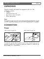
UNPACKING
Unpack carefully and handle the equipment with care. The
packaging contains:
• Camera
• CCD protection cap
• Spare lens connector (male)
• These Instructions
Note:
If equipment appears to have been damaged during shipment, repack
it in the original packaging and notify the shipping agent or supplier.
CONNECTION
Power
LTC 0440/10 and /20
LTC 0440/50 and /60
To open the quick-connect, push in on the tabs. Connections are not
polarity sensitive Use stranded or solid wire AWG16 to AWG22, cut
back 10mm (0.4") of insulation.
Bosch Security Systems | 2004-11
LTC 0440 | Installation Manual
EN | 6
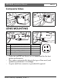
Composite Video
LENS MOUNTING
Pin
Video iris lens
DC iris lens
1
Supply (11 V, 50 mA max.)
Damp-
2
Not used
Damp+
3
Video signal 1 Vpp, 1 kΩ
Drive+
4
Ground
Drive-
•
•
•
Video-iris and DC-iris lenses are recommended for the best
picture performance.
The camera automatically detects the type of lens used, and
optimizes performance accordingly.
A spare male lens connector is provided if required.
Bosch Security Systems | 2004-11
LTC 0440 | Installation Manual
EN | 7
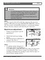
CAUTION
• To avoid damaging the CCD sensor when using a Cmount lens, turn the 'green' back-focus ring counter
clockwise until it stops ('Back focus adjustment')
before mounting the lens.
• Lenses weighing more than 0.5 kg (1.1lbs) must be
separately supported.
Note:
If a short circuit is detected on the lens connector, the on-screen
display (OSD) failure message 'LENS SHORT CIRCUIT' is shown.
The lens circuit is automatically disabled to avoid internal damage.
Remove the lens connector and check the pin connections.
Back focus adjustment
•
Camera accepts both C and CSmount lenses.
1. Unlock the back focus locking
button.
2. Turn the back focus adjustment as
required. (See Note 1).
3. Lock the back focus locking button.
Notes:
1. To optimize picture sharpness in
both bright and low-level lighting, it
is recommended to adjust the back focus when carrying out the
set-up procedure. The camera's unique 'Lens Wizard' allows
focusing at maximum lens opening to ensure that the object of
interest always remains in focus.
Bosch Security Systems | 2004-11
LTC 0440 | Installation Manual
EN | 8
2. When back focusing vari-focus lenses, it must be possible to
obtain a sharp picture in both wide-angle and tele positions, and
for both far and near focus.
3. When back focusing zoom lenses, ensure the object of interest
remains in focus throughout the entire zoom range of the lens.
(See Advanced Set up).
CAUTION
Do not point the camera/lens into direct sunlight. When
viewing an outdoor scene, a video- or DC-iris lens is
recommended.
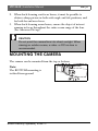
MOUNTING THE CAMERA
The camera can be mounted from the top or bottom.
Note:
The BOTTOM mounting is
isolated from ground.
Bosch Security Systems | 2004-11
LTC 0440 | Installation Manual
EN | 9
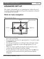
ADVANCED SET-UP
The camera will normally give an optimal picture without the need
for further adjustments. However for special circumstances advanced
set up options are available.
Hints for menu navigation
How to use the 5 keys
Up key
Menu/select key
Right key
Left key
Lock
Down key
•
•
•
•
•
•
Press the menu/select key to access the menus or to move to the
next or previous menu.
Press the menu/select key for approximately 1.5 seconds to open
the Installer menu.
Use the up or down keys to scroll up or down through a menu.
Use the left or right keys to move through options or to set
parameters.
When in a menu, quickly pressing the menu/select key twice
restores the selected item to its factory default.
To close all menus at once from any menu, select the Exit item
and hold down the menu/select key until the menu display
disappears.
Bosch Security Systems | 2004-11
LTC 0440 | Installation Manual
EN | 10
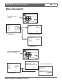
Menu Navigation
Press the menu
button
MAIN MENU
LEVEL
SHUT/AGC
BLC
COLOR
SYNC
VPHASE
SHUT/AGC MENU
0
OFF
ATW
LINE LOCK
0¡
SHUTTER
AGC
AES
ON
EXIT
Main Menu
EXIT
Shutter/AGC Menu
COLOR MENU
WHITE BAL
RED-GAIN
BLUE-GAIN
ATW
0
0
EXIT
Color Menu
Press the menu button
for more than 5sec.
LENS WIZARD
DETECTED LENS
INSTALLER
VERSION
LENS
SPEED
WIZARD
DCIRIS
SET BACK FOCUS NOW
00.0010.XX
AUTO
FAST
DEFAULTS
EXIT
EXIT
Lens Wizard Menus
LENS WIZARD
DETECTED LENS
VIDEO
SET BACK FOCUS NOW
SET LVL
Installer Menu
Bosch Security Systems | 2004-11
EXIT
LTC 0440 | Installation Manual
EN | 11
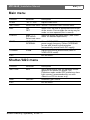
Main menu
Function
Selection
Description
LEVEL
-15 - 0 - +15
Adjusts video level.
SHUT/AGC
Select next menu Shutter / Automatic Gain Control menu.
BLC
ON
OFF
COLOR
ATW
Select to access the color menu. (See Color
ATB HOLD
menu for detailed explanation).
Select next menu
SYNC
LINE LOCK
INTERNAL
Select 'LINE LOCK' to synchronize with the
power supply frequency. Select 'INTERNAL'
for use with internal synchronization
(automatically selected with DC supply).
V PHASE
0-358º
Adjusts the vertical phase offset (when in
'LINE LOCK' mode).
EXIT
When 'ON', the level is optimized at the center
of the screen. Parts outside the center may be
under- or over-exposed (this is normal).
Exit the menu.
Shutter/AGC menu
Function
Selection
Description
SHUTTER
AES
(AES) Auto-shutter sets the optimum shutter
speed FL for manual iris lenses. (FL)
Flickerless mode avoids OFF interference from
light sources (recommended for use with
video-iris or DC-iris lenses only).
AGC
ON/OFF
Automatic gain control
EXIT
Exit the menu.
Bosch Security Systems | 2004-11
LTC 0440 | Installation Manual
EN | 12
Color Menu
Function
Selection
Description
WHITE BAL
ATW
AWB HOLD
ATW: Auto tracking white balance allows the
camera to automatically adjust for optimal
color reproduction.
AWB HOLD: Puts the ATW on hold and
preserves the color settings.
RED- GAIN*
-5 - 0 - +5
Offset factory white point alignment (reducing
red introduces more cyan).
BLUE- GAIN*
-5 - 0 - +5
Offset factory white point alignment (reducing
blue introduces more yellow).
EXIT
Exit the menu.
*Note:
For special scene conditions only, it will be necessary to change the
white point offsets.
Accessing installer menu
•
To access the installer menu, press and hold the menu/select key
for five seconds.
Installer menu
Function
Selection
VERSION
Description
Read-only firmware release number (for
service purposes).
LENS
AUTO
Automatically detect lens type.
A different lens type can be selected.
SPEED
FAST
Selects the response time of DC-iris lenses.
Some lenses require slow lens control to avoid
overshoots.
WIZARD
Access the lens wizard menu.
DEFAULTS
Select next menu Return all set-up settings to
factory defaults.
EXIT
Exit the menu.
Bosch Security Systems | 2004-11
LTC 0440 | Installation Manual
EN | 13
Lens wizard menu
Function
Description
SET BACK FOCUS NOW
Back focus the lens (see 'Back focus adjustment'). The
scene is focused at maximum lens opening to ensure
that the object of interest remains in focus in bright and
low-light conditions.
SET LVL
When a Video-iris lens is detected, a level
potentiometer is displayed to obtain the best picture
performance. The lens wizard includes a level detector
meter that must be set to the center using the
potentiometer for best results.
EXIT
Exit the menu.
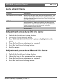
Adjustment procedure DC-iris Lens:
1. Unlock the back focus locking button.
2. Access the "Lens Wizard" menu.
3. The "SET BACK FOCUS NOW" option is highlighted in the
menu.
4. Turn the back focus adjustment as required.
5. Lock the back focus locking button.
6. Exit the menu.
Adjustment procedure Manual-iris Lens:
1.
2.
3.
4.
Unlock the back focus locking button.
Adjust the lens to the maximum lens opening.
Turn the back focus adjustment as required.
Lock the back focus locking button.
Bosch Security Systems | 2004-11
LTC 0440 | Installation Manual
EN | 14
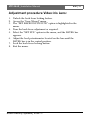
Adjustment procedure Video-iris Lens:
1. Unlock the back focus locking button.
2. Access the "Lens Wizard" menu.
3. The "SET BACK FOCUS NOW" option is highlighted in the
menu.
4. Turn the back focus adjustment as required.
5. Select the "SET LVL" option in the menu, and the LEVEL bar
appears.
6. Adjust the level potentiometer located on the lens until the
LEVEL bar is in the central position.
7. Lock the back focus locking button.
8. Exit the menu.
Bosch Security Systems | 2004-11
Bosch Sicherheitssysteme GmbH
Bosch Security Systems B.V.
Ludwig-Bölkow-Allee
P.O. Box 80002
85521 Ottobrunn
5600 JB Eindhoven
Germany
The Netherlands
www.bosch-sicherheitssysteme.de
www.boschsecuritysystems.com
3122 165 22593 04-50
© 2004 Bosch Security Systems B.V.
Subject to change Printed in Portugal