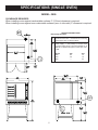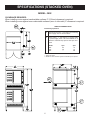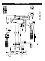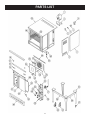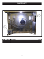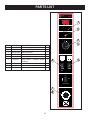
1
OWNER’S MANUAL PREMIER SERIES HIGH PERFORMANCE ELECTRIC CONVECTION OVEN MODELS: m 3000 m 3092 WARNING: FOR YOUR SAFETY: Improper installation, adjustment, alteration, service or maintenance can cause property damage, injury or death. Read these installation, operation and maintenance instructions thoroughly before installing or servicing this equipment. Do not store or use gasoline or other flammable vapors or liquids in the vicinity of this or any other appliance. Form Number: S-6053 Printed in U.S.A. 12/05 35 Garvey Street l Everett l MA l 02149 Tel: (617) 387-4100 l Fax: (617) 387-4456 l Outside MA Fax: (800) 227-2659 E-Mail: [email protected] l Website: www.mfii.com TABLE OF CONTENTS INTRODUCTION ................................................................................................................ IMPORTANT ............................................................................................................ INSTALLATION, OPERATION & SERVICE PERSONNEL ...................................... SHIPPING DAMAGE CLAIM PROCEDURE ........................................................... ii ii ii ii GENERAL ........................................................................................................................... RATING PLATE ........................................................................................................ CLEARANCE ........................................................................................................... SINGLE OVEN ......................................................................................................... DOUBLE OVEN ....................................................................................................... CASTER INSTALLATION ......................................................................................... 1 1 1 1 1 1 ASSEMBLY ......................................................................................................................... 2 STACKING INSTRUCTIONS ................................................................................... 2 IMPORTANT ....................................................................................................................... LEVELING ................................................................................................................ AIR SUPPLY & VENTILATION ................................................................................. ELECTRICAL CONNECTION .................................................................................. FINAL PREPARATION ............................................................................................. 3 3 3 3 3 CLEANING & MAINTENANCE ........................................................................................... CLEANING ............................................................................................................... OVENS .................................................................................................................... STAINLESS STEEL ................................................................................................. PERIODIC MAINTENANCE ..................................................................................... 4 4 4 4 4 SPECIFICATIONS SPECIFICATIONS (SINGLE OVEN) ........................................................................ 5 SPECIFICATIONS (STACKED OVEN) .................................................................... 6 WIRING DIAGRAM ............................................................................................................. 7 PARTS LIST ........................................................................................................................ 9-13 i INTRODUCTION IMPORTANT: Service of the equipment should be performed by qualified personnel who are knowledgeable with Market Forge cooking equipment. Safe and satisfactory operation of your equipment depends on proper installation. Installation must conform with local codes, or in the absence of local codes, the Natonal Electrical Code, (ANSI NFPA-70 Latest Edition). Canadian Electrical Codes (C.S.A. C22.1). SHIPPING DAMAGE CLAIM PROCEDURE: Electrical wiring from the Electric Meter, main control box or service outlet to appliance must be electrically grounded in accordance with local codes or, in the absence of local codes, the National Electric Code (ANSI/NFPA-70 Current). In Canada wiring should conform with Canadian Electrical Code (CSA-C22.1). The equipment is crafted and inspected carefully by skilled personnel before leaving the factory. The transportation company assumes full responsibility for safe delivery upon acceptance of this equipment. If shipment arrives damaged: Visible loss or damage: Note the damage or loss on freight bill or express delivery and signed by the person making the delivery. INSTALLATION, OPERATION & SERVICE PERSONNEL: Installation of the equipment should be performed by qualified, certified, licensed and/or authorized personnel who are familiar with and experienced in state/local installation codes. File claim for damages immediately: Regardless of the extent of damages. Concealed loss or damage: If damage is noticed after unpacking, notify the transportation company immediately and file a “Concealed Damage” claim with them. This should be done within fifteen (15) days from the date delivered. Retain container for inspection. Operation of the equipment should be performed by qualified and authorized personnel who have read this manual and are familiar with the functions of the equipment. ii GENERAL IMPORTANT: To perform maintenance and repairs of the appliance, please contact the factory, factory representative, or the nearest local authorized service company. SINGLE OVEN: Assemble the leg/stand assembly as follows: 1. Remove legs from package. 2. Secure top frame parts to the legs with bolts provided (long angle - front and back. short angle - sides). RATING PLATE: The rating plate is located in front of the oven below the oven section. Information on this plate includes the model, serial number, date of manufacture, and electrical ratings. 3. Place the oven on top of leg/stand assembly. Match holes on the frame with oven bottom base. Fasten with bolts provided. If provided with optional bottom shelf and rack support (Fig. 1) CLEARANCE: The appliance area must be kept free and clear of all combustibles. This unit is design-certified for the following installations only: a. Screw the bottom shelf to the legs. b. Screw rack guide support angles to bottom shelf and top leg frame. The clearances for combustibles and noncombustible construction are as follows: DOUBLE OVEN: 1. Match holes on the legs with oven bottom base and screw with bolts provided. Back / Combustible 6” & Noncombustible 0” Side / Combustible 6” & Noncombustible 0” DO NOT MOUNT over on a curb base. Use legs/ casters provided. Adequate air space at the bottom and rear of the unit must be provided for proper venting of blower motor. 2. Set top oven on top of bottom oven. 3. Bolt down at rear and front as shown in (Fig. 2). Remove top kick plate to access screwing the front bolts. DO NOT USE door to lift or move oven. All ovens must be installed on leg assembly/ casters shipped with unit. OPTIONAL CASTER INSTALLATION: If casters are provided, match holes on the caster with the holes on the oven bottom base and fasten with bolts provided. The leg/stand assembly parts or casters are shipped separately. NOTE: Front casters are locking type. 1 ASSEMBLY STACKING INSTRUCTIONS MODEL 3092 OVENS STEP 1. Attach (4) foot mounting plates and (4) bullet feet onto bottom ove. Set top oven in place on top of bottom oven and slign them in place. STEP 2. Fasten rear mounting plates as shown. STEP 3. Remove the bottom front trim from top oven and the top front trim from the bottom oven. Fasten front mounting plates as shown. STEP 4. Reattach the front trim pieces to ovens. NOTES: 1. Top oven is shown with the bottom trim removed. The bottom oven is shown with the top trim removed. 2. If ovens are supplied with solid back panels, remove them prior to stacking. Fig. 1 Stand Assembly Fig. 2 Stacked Ovens (Model 3092) 2 IMPORTANT LEVELING: A carpenter’s level should be placed on the oven’s center baking rack and the unit leveled both frontto-back and side-to-side. If it is not level, cakes, casseroles, and any other liquid or semi-liquid batter will not bake evenly, and the unit will not function efficiently. FINAL PREPARATION: On initial installation, turn the oven to 250o and operate for about 1 hour, then reset the thermostat to its maximum and operate for another hour. At the end of this second hour, turn the thermostat OFF, open the door and allow the unit to cool. Oven should then be thoroughly washed using hot, soapy water before being used. Units with casters must be leveled with shims. A unit will probably not return to the same position after being moved, requiring releveling after each and every move. Any piece of equipment works better and lasts longer when maintained properly. Cooking equipment is no exception. Your Market Forge oven must be kept clean during the working day and thoroughly cleaned at the end of the day. VENTlLATION: The area, around and above the appliance must be kept clear to avoid any obstruction of air flow needed for ventilation. Adequate clearance must be main-tained at all times in front and at the sides of the appliances for servicing and proper operation. CAUTION: NEVER USE AMMONIA IN AN OVEN THAT IS WARMER THAN ROOM TEMPERATURE AND ALWAYS HAVE DIRECT VENTILATION! ELECTRICAL CONNECTION: 1.The Market Forge Convection Oven requires a 208, 240 or 480 volt supply to operate the heater system and fan motor. Read the data plate before connecting electrical supply to oven. Make sure the electrical supply is the same voltage and frequency called for on the data plate. NOTICE TO THE INSTALLER 2. Ovens may be shipped three phase and may be converted to single phase as per alternate view on wire diagram. IF THIS APPLIANCE IS SUPPLIED WITH CASTERS, UNIT MUST BE CONNECTED USING FLEXIBLE CONDUIT WITH SUITABLE STRAIN RELIEF ATTACHED TO SIDE OF REAR CONNECTION BOX. PLEASE ENSURE CASTER BRAKES ARE ENGAGED AFTER CONNECTION. NOTES: Improper connection to power supply other than that is designated on data plate will voild warranty. This appliance is not capable of being operated in the event of power failure. No attempt should be made to operate this appliance during a power failure. 3 CLEANING & MAINTENANCE DAILY CLEANING: OVENS: 1. Remove the baking racks. Wash in hot soapy water and replace after the rest of the oven is cleaned. 2. Scrape off any food particles with a nylon griddle scraper. Be very careful about scraping the porcelain finish on the oven liner panels. 3. Wash all the above with hot soapy water, then reassemble. 4. Baked on spills may be loosened and stubborn stains removed with ordinary houshold ammonia and scrubbing with a nylon pad in a cold oven only. 5. Do not allow spray type oven cleaners to come into contact with the temperature probe in the oven. 6. After cleaning the oven, rinse well with 1/4 cup of vinegar to one quart of water solution to neutralize any caustic residue of the cleaning compound. Wipe dry. with a liquid cleaner designed for this material at the end of each day. DO NOT USE steel wool, abrasive cloths, cleaners or powders to clean stainless surfaces. If necessary to scrape stainless steel to remove encrusted materials, soak in hot water to loosen the material, then use a wooden nylon scraper. DO NOT USE a metal knife, spatula, or any other metal to scrape stainless steel. Scrape marks are almost impossible to remove. PERIODIC MAINTENANCE: Check the ventilation system periodically to see that nothing has fallen down into the exhaust vents. Lubricate the pivot pins of the oven door hinge. Use a multi-purpose lubricating oil sparingly so as to not drip oil needlessly. Your appliance should be checked for safe and efficient operation at least once a year by qualified service personnel. STAINLESS STEEL: Contact the factory, the factory representativeor a local service company to perform all maintenance and repairs. All stainless steel body parts should be wiped regularly with hot soapy water during the day and 4 SPECIFICATIONS (SINGLE OVEN) MODEL: 3000 CLEARANCE REQUIRED: CLEARANCE REQUIRED: When installing ovens against combustable 6” (152mm) clearance is required. When installing ovens against combustable surfaces 6” surfaces 152mm clearance is required. When installing ovens against non-combustable surfaces (rear or side walls) 0” clearance is required. When installing ovens against non-combustable surfaces (rear or side walls) 0” clearance is required. SERVICE CONNECTIONS Electrically Operated EC Electrical Connection - Connection for incoming power supply wire on terminal block. EP Power supply - 1 3/8 (44mm) access holes for power supply wires. Use wire suitable for at least 90°C. Nominal amp per line wire per oven: 11 kW VOLTS 208V 240V 480V 1pH 53 46 --- 3pH 31 27 14 15 Details of other electrical systems available upon request. 5 SPECIFICATIONS (STACKED OVEN) MODEL: 3092 CLEARANCE REQUIRED: When installing ovens against combustable surfaces 6” (152mm) clearance is required. When installing ovens against non-combustable surfaces (rear or side walls) 0” clearance is required. SERVICE CONNECTIONS Electrically Operated EC Electrical Connection - Connection for incoming power supply wire on terminal block. EP Power supply - 1 3/8 (44mm) access holes for power supply wires. Use wire suitable for at least 90°C. Nominal amp per line wire per oven: 11 kW VOLTS 208V 240V 480V 1pH 53 46 --- 3pH 31 27 14 15 NOTES: 1. Amps Per Oven. 2. Details of other electrical systems available upon request. 6 WIRING DIAGRAM 7 PARTS LIST 8 PARTS LIST ITEM # PART # DESCRIPTOPM QTY. 1 93-0025 MOTOR 1 2 93-0026 MOTOR BRACKET 1 3 93-0021 LIGHT BOX 1 4 93-0022 LIGHT SOCKET 1 5 93-0020 LIGHT BULB 1 6 93-0064 LIGHT COVER 1 8 93-0067 RIGHT SIDE PANEL - REAR 1 9 93-0055 RIGHT SIDE PANEL - FRONT 1 10 93-0017 TERMINAL BLOCK (8-WAY) 1 21 93-0300 MARKET FORGE PREMIER LEXAN DECAL (CONTROL PANEL) 1 22 93-0011 INDICATOR LIGHT 1 KNOB - THERMOSTAT 1 93-0013 SWITCH, FAN - 2-SPEED 1 93-0014 SWITCH, LIGHT - MOMENTARY OVEN LIGHT SWITCH 1 93-0012 SWITCH, POWER - 3 POSITION, ON-OFF-COOL DOWN 1 25 93-0028 KNOB - TIMER 1 26 93-0029 TIMER 1 27 93-0023 THERMOSTAT 60” CAPLINE 1 28 93-0030 DOOR SWITCH - PLUNGER STYLE 1 29 93-0063 KICK PLATE 1 30 93-0059 DOOR ASSY. - R/H WITH GLASS 1 93-0057 DOOR ASSY. - R/H WITH NO GLASS 1 93-0044 GLASS WINDOW ASSY. ONLY 1 31 93-0060 HANDLE - OVEN DOOR 1 32 93-0065 DOOR ASSY. - L/H WITH GLASS 1 93-0058 DOOR ASSY. - L/H WITH NO GLASS 1 33 93-0061 DOOR SEAL - SIDES 1 34 93-0062 DOOR SEAL - TOP & BOTTOM 1 35 93-0040 CHAIN, HT HD PRE STRETCHED 1 93-0041 LINK ROD, 1/4 x 3” W/EYE COUPLER 1 93-0042 LINK ROD, 1/4 x 20” W/EYE COUPLER 1 93-0043 TURN BUCKLE 1 36 93-0056 DOOR CHAIN SPROCKET HOLDER 1 37 93-0070 CHANNEL SPROCKET SUPPORT 1 38 93-0039 BUSHING, 1/2” DIA., BRONZE 1 39 93-0052 BLOWER BAFFLE 1 40 93-0053 SNORKLE TUBE ASSY. 1 41 93-0027 BLOWER WHEEL 1 42 93-0045 BOLT, 1/4-20 x 5, HEX HEAD 1 43 93-0002 SPACER TUBE 3/8” O.D. x 4-1/4” S/S 1 23 24 REF. 93-0023 9 PARTS LIST 44 93-0076 DIVERTER - BOTTOM 1 45 93-0077 DIVERTER - SIDES 1 46 93-0078 DIVERTER - TOP 1 47 93-0074 LEG 6” S/S - WITH ADJUSTABLE FOOT (TSCV-2) 1 48 93-0075 LEG PLATE ASSY. (TSCV-2) 1 52 93-0048 RACK GUIDE - R/H 1 93-0050 RACK GUIDE - L/H 1 53 93-0049 RACK 1 54 93-0069 TOP PANEL 1 56 93-0047 LEG ASSY. (SINGLE UNIT) 1 57 93-0003 FOOT 1 58 93-0072 BOTTOM LEG FRAME - SIDES 1 59 93-0073 BOTTOM LEG FRAME - FRONT & REAR 1 60 93-0007 CASTER W/BRAKES (FRONT) 2 61 93-0006 CASTER W/O BREAKES (REAR) 2 10 PARTS LIST Fig. 5 Heating Elements ITEM # PART # DESCRIPTION QTY. 1 98-4066 208 Volt Heating Elements (Nest of Three) 1 Set 2 98-4067 240 Volt Heating Elements (Nest of Three) 1 Set 3 98-4065 480 Volt Heating Elements (Nest of Three) 1 Set Fig. 6 Terminal Block Contactor & Wire Assembly 11 ITEM # PART # DESCRIPTION QTY. 1 97-4616 Terminal Block Assy. 1 2 10-5944 Contactor 40 Amp. 50/60 Hz (120 Volt) 1 3 98-4096 Fuse 1 4 98-3685 Wire Harness 1 5 08-6469 Fuse Holder 1 PARTS LIST Fig. 7 Electrical ITEM # PART # DESCRIPTION QTY. 1 98-4098 Electrical Box 6” x 6” x 4” 1 2 98-4092 Transformer, 1KVA 1 12 PARTS LIST PREMIER SERIES 1 9 HEAT ON THERMOSTAT O FF 0 60 5 ITEM # PART # DESCRIPTION 1 93-0300 Market Forge Premier Lexan Decal 10 QTY. 93-0023 Thermostat 60” Capline 1 3 REF.93-0023 Thermostat Knob 1 4 93-0013 Switch, Fan Hi-Lo 1 5 93-0014 Switch, Light Momentary Oven Light 1 6 93-0012 Switch Power, 3 Positions On/Off Cooldown 1 7 93-0028 Timer Knob 1 8 93-0029 Timer 1 9 93-0011 Indicator Light, 120 Volt 1 50 15 1 2 55 45 20 40 25 30 35 MODE 4 5 HI ON LO FAN LIGHT POWER ON OFF COOL DOWN TIMER 7 8 0 45 15 30 Fig. 8 Control Panel 13 2 3