1
Model and Manufacturing
numbers listed on pages 4 & 5.
Service
Instructions
48" 90% Condensing Gas Furnaces
GUC, GUD, GUX, GCC, GCD, GDC & Accessories
AIRCOMMAND
HI EFFICIENCY 90GASFURNACE
AIRCOMMAND
HI EFFICIENCY 90GASFURNACE
DE SI GN
CE RT I F I E D
CE
RTIFIE D
®
This manual is to be used by qualified HVAC technicians only. Amana
does not assume any responsibility for property damage or personal injury
due to improper service procedures performed by an unqualified person.
RS6610001
Revision 3
June 2000
INDEX
Important Safety Information ................................................................................... 3
Product Identification ............................................................................................... 4-16
Furnace Specifications ............................................................................................ 17-29
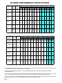
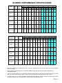
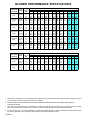
Blower Performance Specifications ........................................................................ 30-35
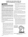
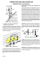
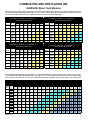
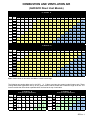
Combustion and Ventilation Air ............................................................................... 36-49
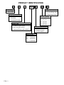
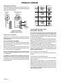
Product Design ........................................................................................................ 50-56
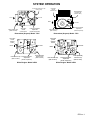
System Operation .................................................................................................... 57-69
Polarization and Phasing........................................................................................ 70
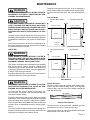
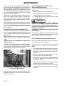
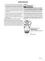
Scheduled Maintenance .......................................................................................... 71-73
Servicing .................................................................................................................. 74-94
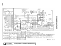
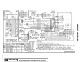
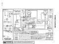
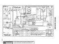
Wiring Diagrams ...................................................................................................... 95-106
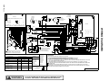
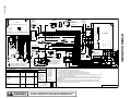
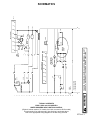
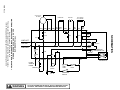
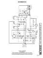
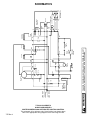
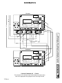
Schematics .............................................................................................................. 107-113
This manual replaces RS6610001 Rev. 2.
REV. 3 - Corrections made to manual, no new models added.
2 Rev. 3
IMPORTANT INFORMATION
Pride and workmanship go into every product to provide our customers with quality products. It is possible, however,
that during its lifetime a product may require service. Products should be serviced only by a qualified service technician
who is familiar with the safety procedures required in the repair and who is equipped with the proper tools, parts,
testing instruments and the appropriate service manual. REVIEW ALL SERVICE INFORMATION IN THE APPROPRIATE SERVICE MANUAL BEFORE BEGINNING REPAIRS.
IMPORTANT NOTICES
WARNING
IF REPAIRS ARE ATTEMPTED BY UNQUALIFIED PERSONS,
DANGEROUS CONDITIONS (SUCH AS EXPOSURE TO ELECTRICAL SHOCK) MAY RESULT. THIS MAY CAUSE SERIOUS INJURY OR DEATH.
AMANA WILL NOT BE RESPONSIBLE FOR ANY INJURY OR
PROPERTY DAMAGE ARISING FROM IMPROPER SERVICE OR
SERVICE PROCEDURES. IF YOU PERFORM SERVICE ON YOUR
OWN PRODUCT, YOU ASSUME RESPONSIBILITY FOR ANY PERSONAL INJURY OR PROPERTY DAMAGE WHICH MAY RESULT.
CAUTION
To locate an authorized servicer, please consult your telephone book or the dealer from whom you purchased this
product. For further assistance, please contact:
CONSUMER AFFAIRS DEPT.
AMANA HEATING & AIR CONDITIONING
AMANA, IOWA 52204
OR
CALL
1-319-622-5511
and ask for
Consumer Affairs
If outside the United States contact:
AMANA HEATING & AIR CONDITIONING
ATTN: INTERNATIONAL DIVISION
AMANA, IOWA 52204, USA
Telephone: (319) 622-5511
Facsimile: (319) 622-2180
RECOGNIZE SAFETY SYMBOLS, WORDS AND LABELS
DANGER
DANGER - Immediate hazards which WILL result in
severe personal injury or death.
WARNING
WARNING - Hazards or unsafe practices which COULD
result in severe personal injury or death.
CAUTION
CAUTION - Hazards or unsafe practices which COULD
result in minor personal injury or product or property damage.
3 Rev. 3
PRODUCT IDENTIFICATION
The model and manufacturing number are used for positive identification of component parts used in manufacturing. At
which time engineering and manufacturing changes take place where interchangeability of components are affected, the
manufacturing number will change.
It is very important to use the model and manufacturing numbers at all times when requesting service or parts information.
MODEL
GUC045B30A
GUC070B30A
GUC070B40A
GUC090B35A
GUC090B50A
GUC115B50A
M/N
P9898401F
P9898402F
P9898403F
P9898404F
P9898405F
P9898406F
GUC045B30B
GUC070B30B
GUC070B40B
GUC090B35B
GUC090B50B
GUC115B50B
P1106901F
P1106902F
P1106903F
P1106904F
P1106905F
P1106906F
GUC045B30C
GUC070B30C
GUC070B40C
GUC090B35C
GUC090B50C
GUC115B50C
P1114301F
P1114302F
P1114303F
P1114304F
P1114305F
P1114306F
GUC045C30C
GUC070C30C
GUC070C40C
GUC090C35C
GUC090C50C
GUC115C50C
P1114307F
P1114308F
P1114309F
P1114310F
P1114311F
P1114312F
GUC045X30A
GUC070X30A
GUC070X40A
GUC090X35A
GUC090X50A
GUC115X50A
P1173601F
P1173602F
P1173603F
P1173604F
P1173605F
P1173606F
GUC045X30B
GUC070X30B
GUC070X40B
GUC090X35B
GUC090X50B
GUC115X50B
P1208701F
P1208702F
P1208703F
P1208704F
P1208705F
P1208706F
GUC045X30B
GUC070X30B
GUC070X40B
GUC090X35B
GUC090X50B
GUC115X50B
P1212901F
P1212902F
P1212903F
P1212904F
P1212905F
P1212906F
4 Rev. 3
MODEL
M/N
GUC090X35BI P1209404F
GCC045B30A
GCC070B30A
GCC070B40A
GCC090B40A
GCC090B50A
GCC115B50A
P9898501F
P9898502F
P9898503F
P9898504F
P9898505F
P9898506F
GCC045B30B
GCC070B30B
GCC070B40B
GCC090B40B
GCC090B50B
GCC115B50B
P1107001F
P1107002F
P1107003F
P1107004F
P1107005F
P1107006F
GCC045C30C
GCC070C30C
GCC070C40C
GCC090C40C
GCC090C50C
GCC115C50C
P1114407F
P1114408F
P1114409F
P1114410F
P1114411F
P1114412F
GCC045C30C
GCC070C30C
GCC070C40C
GCC090C40C
GCC090C50C
GCC115C50C
P1161801F
P1161802F
P1161803F
P1161804F
P1161805F
P1161806F
GCC045X30A
GCC070X30A
GCC070X40A
GCC090X40A
GCC090X50A
GCC115X50A
P1161807F
P1161808F
P1161809F
P1161810F
P1161811F
P1161812F
GUD045B30A P1115001F
GUD070B30A P1115002F
GUD070B40A P1115003F
GUD090B35A P1115004F
GUD090B50A P1115005F
GUD115B50A P1115006F
GUD045C30A
GUD070C30A
GUD070C40A
GUD090C35A
GUD090C50A
GUD115C50A
P1115007F
P1115008F
P1115009F
P1115010F
P1115011F
P1115012F
MODEL
GUD045C30A
GUD070C30A
GUD070C40A
GUD090C35A
GUD090C50A
GUD115C50A
M/N
P1164501F
P1164502F
P1164503F
P1164504F
P1164505F
P1164506F
MODEL
GUX045X30A
GUX070X30A
GUX070X40A
GUX090X35A
GUX090X50A
GUX115X50A
M/N
P1161707F
P1161708F
P1161709F
P1161710F
P1161711F
P1161712F
GUD045X30A
GUD070X30A
GUD070X40A
GUD090X35A
GUD090X50A
GUD115X50A
P1164507F
P1164508F
P1164509F
P1164510F
P1164511F
P1164512F
GUX045X30B
GUX070X30B
GUX070X40B
GUX090X35B
GUX090X50B
GUX115X50B
P1207801F
P1207802F
P1207803F
P1207804F
P1207805F
P1207806F
GUD045X30B
GUD070X30B
GUD070X40B
GUD090X35B
GUD090X50B
GUD115X50B
P1208001F
P1208002F
P1208003F
P1208004F
P1208005F
P1208006F
GUX045X30B
GUX070X30B
GUX070X40B
GUX090X35B
GUX090X50B
GUX115X50B
P1213001F
P1213002F
P1213003F
P1213004F
P1213005F
P1213006F
GUD045X30B
GUD070X30B
GUD070X40B
GUD090X35B
GUD090X50B
GUD115X50B
P1213101F
P1213102F
P1213103F
P1213104F
P1213105F
P1213106F
GUX070X30BI P1209302F
GUX045B30A
GUX070B30A
GUX070B40A
GUX090B35A
GUX090B50A
GUX115B50A
P1119801F
P1119802F
P1119803F
P1119804F
P1119805F
P1119806F
GUX045B30A
GUX070B30A
GUX070B40A
GUX090B35A
GUX090B50A
GUX115B50A
P1161701F
P1161702F
P1161703F
P1161704F
P1161705F
P1161706F
GDC045X30B
GDC070X30B
GDC070X40B
GDC090X40B
GDC090X50B
GDC115X50B
P1208101F
P1208102F
P1208103F
P1208104F
P1208105F
P1208106F
GDC045X30B
GDC070X30B
GDC070X40B
GDC090X40B
GDC090X50B
GDC115X50B
P1213201F
P1213202F
P1213203F
P1213204F
P1213205F
P1213206F
GCD070X30B P1212802F
GCD090X40B P1212804F
GCD070X30B P1217602F
GCD090X40B P1217604F
PRODUCT IDENTIFICATION
The model and manufacturing number are used for positive identification of component parts used in manufacturing. At
which time engineering and manufacturing changes take place where interchangeability of components are affected, the
manufacturing number will change.
It is very important to use the model and manufacturing numbers at all times when requesting service or parts information.
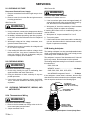
FURNACE ACCESSORY KITS
ADDITIONAL FURNACE ACCESSORY KITS
FFK_
Fossil Fuel Kit
CCC_ Counterflow Coil Cabinet Assembly
FTK_
Furnace Twinning Kit
CCU_ Coil Cabinet Upflow Assembly
HANG_ High Altitude Natural Gas Kit
HALP_ High Altitude LP Kit
HAPS_ High Altitude Pressure Switch Kit
Note: For the two additional furnace accessory kits listed
above, see accessory parts catalog for available kits and
usage.
LPTK_ LP Conversion Kit
CFC_ Counterflow Filter Cabinet Assembly
Note: For the furnace accessory kits listed above, see servicing section for available kits and usage.
CFSB_ Counterflow Subbase
CFRK_ Counterflow Filter Rack Kit
EAC_
Electronic Air Cleaner
EFR_
External Filter Rack Kit
HDF_ Horizontal Duct Flange Kit
HFC_ Horizontal Filter Cabinet Assembly
MAC_ Media Air Cleaner
MAF_ Media Air Filter (Replacement Filter For MAC_)
Note: For additional furnace accessory kits listed above,
see product identification section pages 14, 15 and 16 for
available kits and usage.
5 Rev. 3
PRODUCT IDENTIFICATION
G
U
C
045 B
50
B
Product Type
Design Series
G: Gas Furnace
A:
B:
C:
Supply Type
U: Upflow
Airflow Capability
C: Counterflow
25:
30:
35:
40:
50:
D: Counterflow/Horizontal
Furnace Type
2.5 Tons
3.0 Tons
3.5 Tons
4.0 Tons
5.0 Tons
C: Condensing (90% AFUE)
Feature Designator
D: Direct Vent (90% AFUE)
X: Enhanced Efficiency (95% AFUE)
B: Standard Domestic Line
C: Integrated Control
X: Low NOx Models
Nominal Input
045: 45,000 Btuh
070: 70,000 Btuh
090: 90,000 Btuh
115: 115,000 Btuh
6 Rev. 3
First Design Series
Second Design Series
Third Design Series
PRODUCT IDENTIFICATION
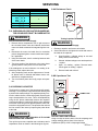
FOR YOUR SAFETY
READ BEFORE OPERATING
WARNING: If you do not follow these instructions
explosion may result causing property damage,
personal injury or loss of life.
A. This appliance does not have a pilot. It is equipped
with an ignition device which automatically lights
the burner. Do not try to light the burner by hand.
B. BEFORE OPERATING smell all around the appliance
area for gas. Be sure to smell next to the floor
because some gas is heavier than air and will
settle on the floor.
WHAT TO DO IF YOU SMELL GAS
Do not try to light any appliance.
Do not touch any electric switch;
do not use any phone in your building.
Immediately call your gas supplier from a neighbor's
phone. Follow the gas supplier's instructions.
If you cannot reach your gas supplier,
call the fire department.
C. Use only your hand to turn the gas control knob.
Never use tools. If the knob will not turn by
hand, don't try to repair it, call a qualified service
technician. Force or attempted repair may result in a fire
or explosion.
D. Do not use this appliance if any part has been underwater.
Immediately call a qualified service technician to inspect
the appliance and to replace any part of the control
system and any gas control which has been underwater.
LIRE AVANT DE METTRE
EN MARCHELIRE
AVERTISSEMENT: Quiconque ne respecte pas á
la lettre les instructions dans le présent manuel
risque de déclecher un incendie ou une explosion
entraînant des dammages matériels, des lésions
corporelles ou la perte de vies humaines.
A.
Cet appareil ne comporte pas de veilleuse. Il est
muni d'un dispositif d'allumage qui allume
automatiquement le brûleur. Ne pas tenter
d'allumer le brûleur manuellement.
B. AVANT DE LE FAIRE FONCTIONNER,
renifler tout autour de l'appariel pour déceler
une odeur de gaz. Renifler près du plancher, car
certains gaz sont plus lourds que l'air et
peuvent s'accumuler au niveau du so.l
QUE FAIRE S'IL Y A UNE ODEUR DE GAZ
Ne pas tenter d'allumer l'appariel
Ne toucher aucun interrupteur électrique;
n'utiliser aucun téléphone dans le bâtiment.
Appeler immédiatement le fournisseur de gaz
en employant le téléphone dún voisin.
Respecter à la lettre les instructions du
fournisseur de gaz.
Si personne ne répond, appeler le service des
incendies.
C. Ne pousser ou tourner le robinet d'admission du gaz
qu'à la main; ne jamais emploer d'outil à cet effet.
Si la manette reste coincée, ne pas tenter de la
réparer; appeler un technicien qualifié. Quiconque
tente de forcer la manette ou de la reparer peut
déclencher une explosion ou un incendie.
D. Ne pas se servir de cet appareil s'il a été plongé
dans l'eau, complètement ou en partie. Appeler un
technicien qualifié pour inspecter l'appareil et
remplacer tout partie du système de contrôle et
toute commande qui ont été plongés dans l'eau.
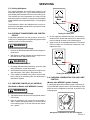
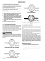
OPERATING INSTRUCTIONS
1. STOP! Read the safety information above on
this label.
2. Set the thermostat to lowest setting.
3. Turn off all power to the appliance.
4. This appliance is equipped with an ignition.
device which automatically lights the burner.
Do not try to light the burner by hand.
5. Turn the gas control knob clockwise
to
"OFF" Position. Do not force.
6. Wait five (5) minutes to clear out any gas. Then
smell for gas, including near the floor. If you
then smell gas, STOP! Follow "B" in the safety
information above on this Label.
ROBINET A GAZ
MANUEL, EN POS
If you don't smell gas, go to
"ON/MARCHE"
next step.
7. Turn gas control knob
counterclockwise
to "ON".
GAS
INLET
8. Replace access panel.
9. Turn on all electric
power to the appliance.
ARRIVEE
10.Set thermostat to desired setting.
DU GAZ
11.If the appliance will not operate,
follow the instructions "To Turn
Off Gas To Appliance" and call your
MANUAL GAS
service technician or gas company.
MISE EN MARCHE
1. ARRETÊR! Lisez les instructions de sécurité sur
la portion supérieure de cette étiquette.
. 2. Régler le thermostat à la température la plus basse
3. Couper l'alimentation électrique de l'appareil.
4. Cet appareil ménager étant doté d'un système
d'allumage automatique, ne pas essayer à
allumer le brûleur manuellement.
5. Torner le robinet a gaz dans le sens des aigilles
d'une montre
en position "OFF/ARRET"
6. Attendre cinq (5) minutes pour laisser echapper tout le
gaz. Renifler tout autour de l'appareil, y compris près du
plancher, pour déceler une odeur de gaz. Si c'est le cas,
ARRETER! Passer à l'étape B des instructions de sécuritié
sur la portion supérieure de cette étiquette.
S'il n'y a pas d'odeur de gaz, passer à l'étape suivanté.
7. T ourner le robinet a gaz dans le sens inverse des
aigilles d'ne montre
en pos "ON/MARCHE".
8. Remettre en place le panneau d'accés.
9. Mettre l'appareil sous tension.
10. Régler le thermostat à la température desirée.
11. Si l'appareil ne se met pas en marche, suiyre les
instructions intitulées. Comment coupler l'admission
de gaz de l'appereil et appeler un technicien
qualifié ou le fourrnisseur de gaz.
OFF
ON
Hone ywe ll
KNOB SHOWN
IN "ON" POSITION
TO TURN OFF GAS TO APPLIANCE
1. Set the thermostat to lowest setting.
2. Turn off all electric power to the appliance
if service is to be performed.
3. Turn the gas control knob clockwise
to
"OFF" Position. Do not force.
4. Replace control access panel.
POUR COUPER L'ADMISSION
DE GAZ DE L'APPAREIL
1. Régler le thermostat à la température la plus basse.
2. Couper l'alimentation électrique de l'appareil s'il
faut procéder à des opérations d'entretien.
3. Torner le robinet a gaz dans le sens des aigilles
d'une montre
en position "OFF/ARRET".
Ne pas forcer.
4. Remettre en place le panneau d'accès.
11 07270 2
7 Rev. 3
PRODUCT IDENTIFICATION
FOR YOUR SAFETY
READ BEFORE OPERATING
LIRE AVANT DE METTRE
EN MARCHELIRE
WARNING: If you do not follow these instructions
AVERTISSEMENT: Quiconque ne respecte pas á
explosion may result causing property damage,
personal injury or loss of life.
la lettre les instructions dans le présent manuel
risque de déclecher un incendie ou une explosion
entraînant des dammages matériels, des lésions
corporelles ou la perte de vies humaines.
A. This appliance does not have a pilot. It is equipped
with an ignition device which automatically lights
the burner. Do not try to light the burner by hand.
A.
B. BEFORE OPERATING smell all around the appliance
area for gas. Be sure to smell next to the floor
because some gas is heavier than air and will
settle on the floor.
Cet appareil ne comporte pas de veilleuse. Il est
muni d'un dispositif d'allumage qui allume
automatiquement le brûleur. Ne pas tenter
d'allumer le brûleur manuellement.
B. AVANT DE LE FAIRE FONCTIONNER,
renifler tout autour de l'appariel pour déceler
une odeur de gaz. Renifler près du plancher, car
certains gaz sont plus lourds que l'air et
peuvent s'accumuler au niveau du so.l
WHAT TO DO IF YOU SMELL GAS
Do not try to light any appliance.
Do not touch any electric switch;
do not use any phone in your building.
Immediately call your gas supplier from a neighbor's
phone. Follow the gas supplier's instructions.
If you cannot reach your gas supplier,
call the fire department.
QUE FAIRE S'IL Y A UNE ODEUR DE GAZ
Ne pas tenter d'allumer l'appariel
Ne toucher aucun interrupteur électrique;
n'utiliser aucun téléphone dans le bâtiment.
Appeler immédiatement le fournisseur de gaz
en employant le téléphone dún voisin.
Respecter à la lettre les instructions du
fournisseur de gaz.
Si personne ne répond, appeler le service des
incendies.
C. Ne pousser ou tourner le robinet d'admission du gaz
qu'à la main; ne jamais emploer d'outil à cet effet.
Si la manette reste coincée, ne pas tenter de la
réparer; appeler un technicien qualifié. Quiconque
tente de forcer la manette ou de la reparer peut
déclencher une explosion ou un incendie.
C. Use only your hand to turn the gas control knob.
Never use tools. If the knob will not turn by
hand, don't try to repair it, call a qualified service
technician. Force or attempted repair may result in a fire
or explosion.
D. Do not use this appliance if any part has been underwater.
Immediately call a qualified service technician to inspect
the appliance and to replace any part of the control
system and any gas control which has been underwater.
D. Ne pas se servir de cet appareil s'il a été plongé
dans l'eau, complètement ou en partie. Appeler un
technicien qualifié pour inspecter l'appareil et
remplacer tout partie du système de contrôle et
toute commande qui ont été plongés dans l'eau.
OPERATING INSTRUCTIONS
1. ARRETÊR! Lisez les instructions de sécurité sur
la portion supérieure de cette étiquette.
. 2. Régler le thermostat à la température la plus basse
3. Couper l'alimentation électrique de l'appareil.
4. Cet appareil ménager étant doté d'un système
d'allumage automatique, ne pas essayer à
allumer le brûleur manuellement.
5. Torner le robinet a gaz dans le sens des aigilles
d'une montre
ROBINET A GAZ
MANUEL, EN POS
"ON/MARCHE"
PIL OT A DJ
ON
ARRIVEE
DU GAZ
MANUAL GAS
KNOB SHOWN
IN "ON" POSITION
TO TURN OFF GAS TO APPLIANCE
1. Set the thermostat to lowest setting.
2. Turn off all electric power to the appliance
if service is to be performed.
3. Turn the gas control knob clockwise
to
"OFF" Position. Do not force.
4. Replace control access panel.
GAS
INLET
en position "OFF/ARRET"
6. Attendre cinq (5) minutes pour laisser echapper tout le
gaz. Renifler tout autour de l'appareil, y compris près du
plancher, pour déceler une odeur de gaz. Si c'est le cas,
ARRETER! Passer à l'étape B des instructions de sécuritié
sur la portion supérieure de cette étiquette.
S'il n'y a pas d'odeur de gaz, passer à l'étape suivanté.
7. T ourner le robinet a gaz dans le sens inverse des
aigilles d'ne montre
OFF
1. STOP! Read the safety information above on
this label.
2. Set the thermostat to lowest setting.
3. Turn off all power to the appliance.
4. This appliance is equipped with an ignition.
device which automatically lights the burner.
Do not try to light the burner by hand.
5. Turn the gas control knob clockwise
to
"OFF" Position. Do not force.
6. Wait five (5) minutes to clear out any gas. Then
smell for gas, including near the floor. If you
then smell gas, STOP! Follow "B" in the safety
information above on this Label.
If you don't smell gas, go to
next step.
7. Turn gas control knob
counterclockwise
to "ON".
8. Replace access panel.
9. Turn on all electric
power to the appliance.
10.Set thermostat to desired setting.
11.If the appliance will not operate,
follow the instructions "To Turn
Off Gas To Appliance" and call your
service technician or gas company.
MISE EN MARCHE
en pos "ON/MARCHE".
8. Remettre en place le panneau d'accés.
9. Mettre l'appareil sous tension.
10. Régler le thermostat à la température desirée.
11. Si l'appareil ne se met pas en marche, suiyre les
instructions intitulées. Comment coupler l'admission
de gaz de l'appereil et appeler un technicien
qualifié ou le fourrnisseur de gaz.
POUR COUPER L'ADMISSION
DE GAZ DE L'APPAREIL
1. Régler le thermostat à la température la plus basse.
2. Couper l'alimentation électrique de l'appareil s'il
faut procéder à des opérations d'entretien.
3. Torner le robinet a gaz dans le sens des aigilles
d'une montre
en position "OFF/ARRET".
Ne pas forcer.
4. Remettre en place le panneau d'accès.
11 072703
8 Rev. 3
PRODUCT IDENTIFICATION
FOR YOUR SAFETY
READ BEFORE OPERATING
LIRE AVANT DE METTRE
EN MARCHELIRE
WARNING: If you do not follow these instructions
AVERTISSEMENT: Quiconque ne respecte pas á
explosion may result causing property damage,
personal injury or loss of life.
la lettre les instructions dans le présent manuel
risque de déclecher un incendie ou une explosion
entraînant des dammages matériels, des lésions
corporelles ou la perte de vies humaines.
A. This appliance does not have a pilot. It is equipped
with an ignition device which automatically lights
the burner. Do not try to light the burner by hand.
A.
B. BEFORE OPERATING smell all around the appliance
area for gas. Be sure to smell next to the floor
because some gas is heavier than air and will
settle on the floor.
Cet appareil ne comporte pas de veilleuse. Il est
muni d'un dispositif d'allumage qui allume
automatiquement le brûleur. Ne pas tenter
d'allumer le brûleur manuellement.
B. AVANT DE LE FAIRE FONCTIONNER,
renifler tout autour de l'appariel pour déceler
une odeur de gaz. Renifler près du plancher, car
certains gaz sont plus lourds que l'air et
peuvent s'accumuler au niveau du so.l
WHAT TO DO IF YOU SMELL GAS
Do not try to light any appliance.
Do not touch any electric switch;
do not use any phone in your building.
Immediately call your gas supplier from a neighbor's
phone. Follow the gas supplier's instructions.
If you cannot reach your gas supplier,
call the fire department.
QUE FAIRE S'IL Y A UNE ODEUR DE GAZ
Ne pas tenter d'allumer l'appariel
Ne toucher aucun interrupteur électrique;
n'utiliser aucun téléphone dans le bâtiment.
Appeler immédiatement le fournisseur de gaz
en employant le téléphone dún voisin.
Respecter à la lettre les instructions du
fournisseur de gaz.
Si personne ne répond, appeler le service des
incendies.
C. Ne pousser ou tourner le robinet d'admission du gaz
qu'à la main; ne jamais emploer d'outil à cet effet.
Si la manette reste coincée, ne pas tenter de la
réparer; appeler un technicien qualifié. Quiconque
tente de forcer la manette ou de la reparer peut
déclencher une explosion ou un incendie.
C. Use only your hand to turn the gas control knob.
Never use tools. If the knob will not turn by
hand, don't try to repair it, call a qualified service
technician. Force or attempted repair may result in a fire
or explosion.
D. Do not use this appliance if any part has been underwater.
Immediately call a qualified service technician to inspect
the appliance and to replace any part of the control
system and any gas control which has been underwater.
D. Ne pas se servir de cet appareil s'il a été plongé
dans l'eau, complètement ou en partie. Appeler un
technicien qualifié pour inspecter l'appareil et
remplacer tout partie du système de contrôle et
toute commande qui ont été plongés dans l'eau.
OPERATING INSTRUCTIONS
1. STOP! Read the safety information above on
this label.
2. Set the thermostat to lowest setting.
3. Turn off all power to the appliance.
4. This appliance is equipped with an ignition.
device which automatically lights the burner.
Do not try to light the burner by hand.
5. Turn the gas control lever clockwise
to
"OFF" Position. Do not force.
6. Wait five (5) minutes to clear out any gas. Then
smell for gas, including near the floor. If you
then smell gas, STOP! Follow "B" in the safety
information above on this Label.
If you don't smell gas, go to
next step.
7. Turn gas control lever
counterclockwise
to "ON".
8. Replace access panel.
9. Turn on all electric
power to the appliance.
10.Set thermostat to desired setting.
11.If the appliance will not operate,
follow the instructions "To Turn
Off Gas To Appliance" and call your
service technician or gas company.
MISE EN MARCHE
LEVIER A GAZ
MANUEL, EN POS
"ON/MARCHE"
GAS
INLET
ARRIVEE
DU GAZ
aigilles d'ne montre
en pos "ON/MARCHE".
8. Remettre en place le panneau d'accés.
9. Mettre l'appareil sous tension.
10. Régler le thermostat à la température desirée.
11. Si l'appareil ne se met pas en marche, suiyre les
instructions intitulées. Comment coupler l'admission
de gaz de l'appereil et appeler un technicien
qualifié ou le fourrnisseur de gaz.
MANUAL GAS
LEVER SHOWN
IN "ON" POSITION
TO TURN OFF GAS TO APPLIANCE
1. Set the thermostat to lowest setting.
2. Turn off all electric power to the appliance
if service is to be performed.
3. Turn the gas control lever clockwise
to
"OFF" Position. Do not force.
4. Replace control access panel.
1. ARRETÊR! Lisez les instructions de sécurité sur
la portion supérieure de cette étiquette.
. 2. Régler le thermostat à la température la plus basse
3. Couper l'alimentation électrique de l'appareil.
4. Cet appareil ménager étant doté d'un système
d'allumage automatique, ne pas essayer à
allumer le brûleur manuellement.
5. Torner le levier a gaz dans le sens des aigilles
en position "OFF/ARRET"
d'une montre
6. Attendre cinq (5) minutes pour laisser echapper tout le
gaz. Renifler tout autour de l'appareil, y compris près du
plancher, pour déceler une odeur de gaz. Si c'est le cas,
ARRETER! Passer à l'étape B des instructions de sécuritié
sur la portion supérieure de cette étiquette.
S'il n'y a pas d'odeur de gaz, passer à l'étape suivanté.
7. Tourner le levier a gaz dans le sens inverse des
POUR COUPER L'ADMISSION
DE GAZ DE L'APPAREIL
1. Régler le thermostat à la température la plus basse.
2. Couper l'alimentation électrique de l'appareil s'il
faut procéder à des opérations d'entretien.
3. Torner le levier a gaz dans le sens des aigilles
d'une montre
en position "OFF/ARRET".
Ne pas forcer.
4. Remettre en place le panneau d'accès.
11 07270 6
9 Rev. 3
PRODUCT IDENTIFICATION
FOR YOUR SAFETY
READ BEFORE OPERATING
LIRE AVANT DE METTRE
EN MARCHELIRE
WARNING: If you do not follow these instructions
AVERTISSEMENT: Quiconque ne respecte pas á
explosion may result causing property damage,
personal injury or loss of life.
la lettre les instructions dans le présent manuel
risque de déclecher un incendie ou une explosion
entraînant des dammages matériels, des lésions
corporelles ou la perte de vies humaines.
A. This appliance does not have a pilot. It is equipped
with an ignition device which automatically lights
the burner. Do not try to light the burner by hand.
A.
B. BEFORE OPERATING smell all around the appliance
area for gas. Be sure to smell next to the floor
because some gas is heavier than air and will
settle on the floor.
Cet appareil ne comporte pas de veilleuse. Il est
muni d'un dispositif d'allumage qui allume
automatiquement le brûleur. Ne pas tenter
d'allumer le brûleur manuellement.
B. AVANT DE LE FAIRE FONCTIONNER,
renifler tout autour de l'appariel pour déceler
une odeur de gaz. Renifler près du plancher, car
certains gaz sont plus lourds que l'air et
peuvent s'accumuler au niveau du so.l
WHAT TO DO IF YOU SMELL GAS
Do not try to light any appliance.
Do not touch any electric switch;
do not use any phone in your building.
Immediately call your gas supplier from a neighbor's
phone. Follow the gas supplier's instructions.
If you cannot reach your gas supplier,
call the fire department.
QUE FAIRE S'IL Y A UNE ODEUR DE GAZ
Ne pas tenter d'allumer l'appariel
Ne toucher aucun interrupteur électrique;
n'utiliser aucun téléphone dans le bâtiment.
Appeler immédiatement le fournisseur de gaz
en employant le téléphone dún voisin.
Respecter à la lettre les instructions du
fournisseur de gaz.
Si personne ne répond, appeler le service des
incendies.
C. Ne pousser ou tourner le levier d'admission du gaz
qu'à la main; ne jamais emploer d'outil à cet effet.
Si la manette reste coincée, ne pas tenter de la
réparer; appeler un technicien qualifié. Quiconque
tente de forcer la manette ou de la reparer peut
déclencher une explosion ou un incendie.
C. Use only your hand to push in or turn the gas control lever.
Never use tools. If the lever will not push in or turn by
hand, don't try to repair it, call a qualified service
technician. Force or attempted repair may result in a fire
or explosion.
D. Do not use this appliance if any part has been underwater.
Immediately call a qualified service technician to inspect
the appliance and to replace any part of the control
system and any gas control which has been underwater.
D. Ne pas se servir de cet appareil s'il a été plongé
dans l'eau, complètement ou en partie. Appeler un
technicien qualifié pour inspecter l'appareil et
remplacer tout partie du système de contrôle et
toute commande qui ont été plongés dans l'eau.
OPERATING INSTRUCTIONS
MISE EN MARCHE
1. STOP! Read the safety information above on
this label.
2. Set the thermostat to lowest setting.
3. Turn off all power to the appliance.
4. This appliance is equipped with an ignition.
device which automatically lights the burner.
Do not try to light the burner by hand.
5. Push the gas control lever to "OFF" Position.
Do not force.
6. Wait five (5) minutes to clear out any gas. Then
smell for gas, including near the floor. If you
LEVIER A GAZ
then smell gas, STOP! Follow "B"
MANUEL, EN POS
in the safety. Information above
"ON/MARCHE"
on this label if you don't smell
GAS
gas, go to next step.
INLET
7. Push gas control lever
to "ON".
8. Replace access panel.
ARRIVEE
9. Turn on all electric
DU GAZ
power to the appliance.
10.Set thermostat to desired setting.
MANUAL GAS
11.If the appliance will not operate,
LEVER SHOWN
follow the instructions "To Turn
IN
ON POSITION
Off Gas To Appliance" and call your
service technician or gas company.
*
*
O
F
F
*
M
1
P
3
*
2
C
ON
*
*
TO TURN OFF GAS TO APPLIANCE
1. Set the thermostat to lowest setting.
2. Turn off all electric power to the appliance
if service is to be performed.
3. Push the gas control lever to "OFF" Position.
Do not force.
4. Replace control access panel.
*
1. ARRETÊR! Lisez les instructions de sécurité sur
la portion supérieure de cette étiquette.
. 2. Régler le thermostat à la température la plus basse
3. Couper l'alimentation électrique de l'appareil.
4. Cet appareil ménager étant doté d'un système
d'allumage automatique, ne pas essayer à
allumer le brûleur manuellement.
5. Pousse le levier du contrôle du gaz à "OFF/ ARRET"
position.
6. Attendre cinq (5) minutes pour laisser echapper tout le
gaz. Renifler tout autour de l'appareil, y compris près du
plancher, pour déceler une odeur de gaz. Si c'est le cas,
ARRETER! Passer à l'étape B des instructions de sécuritié
sur la portion supérieure de cette étiquette.
S'il n'y a pas d'odeur de gaz, passer à l'étape suivanté.
7. Pousse le levier du contrôle du gaz à "ON/MARCHE"
position.
8. Remettre en place le panneau d'accés.
9. Mettre l'appareil sous tension.
10. Régler le thermostat à la température desirée.
11. Si l'appareil ne se met pas en marche, suiyre les
instructions intitulées. Comment coupler l'admission
de gaz de l'appereil et appeler un technicien
qualifié ou le fourrnisseur de gaz.
POUR COUPER L'ADMISSION
DE GAZ DE L'APPAREIL
1. Régler le thermostat à la température la plus basse.
2. Couper l'alimentation électrique de l'appareil s'il
faut procéder à des opérations d'entretien.
3. Pousse le levier du contrôle du gaz à "OFF / ARRET"
position.
Ne pas forcer.
4. Remettre en place le panneau d'accès.
11 07270 7
10 Rev. 3
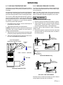
PRODUCT IDENTIFICATION
Left Side View
3/4
Front View
28-1/8
28
20-1/8
A
F
Gas
Supply
Electrical Hole
Hole-Low
Voltage
1-5/8
B
3/4
3/4
C
6-5/8
E
Supply
Electrical
Hole-Line
Voltage
Right Side View
4-3/4
Supply
Electrical
Hole-Low
Voltage
®
Hea ting ¡ Air Conditio nin g
A hig her s tandar d o f co m for t
48
5-3/8
38-3/4
Gas
Supply
Hole
41-3/8
6-5/8
38-1/4
23
38-3/4
14
Side Knock Out
28-3/4
Condensate Drain
1-5/8
1-5/8
Side Knock Out
16-1/2
(Left or Right Side)
D
Bottom Knock Out
23
Bottom Knock Out
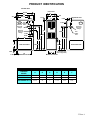
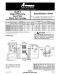
UPFLOW FURNACE DIMENSIONS
FURNACE
MODEL
A
B
C
D
E
F
GUC/GUX045
GUC/GUX070
16-1/2
15
2
10-1/2
4-1/4
2-3/8
20-1/2
19
2
14-1/2
4-1/4
2-3/8
GUC/GUX090 & 115
24-1/2
23
2
1/-1/2
4-1/4
2-3/8
All dimensions are in inches.
11 Rev. 3
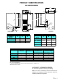
PRODUCT IDENTIFICATION
Top View
Combustion
Air Inlet
Gas Supply Hole
Electrical Hole
Line Voltage
Flue Outlet
4-1/4
1-3/4
2
4-3/8
1-1/8
2-1/2
C
E
Left Side View
3/4
28-1/8
28
20-1/8
Front View
A
B
3/4
2-3/8
3/4
Gas
Supply
Electrical Hole
Supply
Hole-Low
Voltage
Right Side View
6-5/8
4-3/4
1-5/8
Supply
Electrical
Hole-Low
Voltage
AIRCOMMAND
HIEFFICIENCY90GASFURNACE
48
Electrical
Hole-Line
Voltage 5-7/8
38-1/4
Gas
Supply
Hole
40
6-5/8
23
33-3/4
38-3/4
14
Side KO
28-3/4
16-1/2
1-5/8
1-5/8
Condensate Drain
(Left or Right Side)
D
23
Bottom Knock Out
Bottom Knock Out
UPFLOW FURNACE DIMENSIONS
FURNACE
MODEL
GUD045
GUD070
GUD090
GUD115
12 Rev. 3
A
B
C
D
E
16-1/2
15
7
10-1/2
2-5/8
20-1/2
19
11
14-1/2
2-5/8
24-1/2
23
10-1/2
18-1/2
4-5/8
24-1/2
23
12-1/2
18-1/2
2-5/8
All dimensions are in inches.
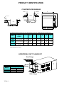
PRODUCT IDENTIFICATION
ACCESSORIES
28-1/8"
A
20-1/4"
3/4"
C
2"
3/4"
2-3/8"
28-3/4"
38-3/4"
38-1/4"
41-3/8"
41-3/8"
48"
6-5/8"
5-3/8"
Electrical
Hole "Low
Voltage"
Electrical
Holes "Low
Voltage"
1-5/8"
A Ra ythe on Compan y
Supply
Supply
Gas
Supply
Hole
14-7/8"
Gas
Supply
Hole
4-3/4"
6-5/8"
B
Counterflow
Left Side View
5/8"
Counterflow
Front View
Counterflow
Right Side View
COUNTERFLOW FURNACE DIMENSIONS
FURNACE
A
B
C
MODEL
16-1/2
15-7/8
15
GDC045
COUNTERFLOW FURNACE DIMENSIONS
FURNACE
A
B
C
MODEL
16-1/2
15-1/4
14-15/16
GCC045
20-1/2
19-1/4
18-15/16
GCC070
24-1/2
23-1/4
22-15/16
GCC090 & 115
All dimensions are in inches.
GDC / GCD070
20-1/2
19-7/8
19
GDC / GCD090
24-1/2
23-7/8
23
GDC115
24-1/2
23-7/8
23
All dimensions are in inches.
MINIMUM CLEARANCES TO COMBUSTABLE SURFACES
HORIZONTAL
HORIZONTAL
UPFLOW
COUNTERFLOW
DISCHRAGE LEFT
DISCHARGE RIGHT
(GDC MODELS ONLY) (GDC MODELS ONLY)
FRONT
LEFT SIDE
RIGHT SIDE
REAR
TOP
FLUE
FLOOR
3
3
Alcove
Alcove
1
1
1
1
6
12
12
6
0
1
0
C
0
1
0
NC*
0
6
0
C
0
6
0
C
C = If placed on combustible floor, floor MUST be wood only.
NC = Non-combustible floor.
* = May be combustable floor (wood only) with special subase no. CFSB20, or 24.
All dimensions are in inches.
ACCESSIBILITY CLEARANCES (MINIMUM)
36" at front is required for servicing or cleaning.
Note: In all cases accessiblility clearance shall take precedence over clearances from the enclosure where accessibility clearances are greater.
13 Rev. 3
PRODUCT IDENTIFICATION
COUNTERFLOW SUBBASE
Sub-Base
Gasket
D
Floor
1" Min.
Plenum
Furnace Front
C
2"
3/4"
F
E
Front View
Plenum
3/4"
A
3/4"
A
4-7/16"
B
B
Side View
F
G
E
Counterflow subbase required when GCC,GCD & GDC furnaces are installed directly on wooden floor.
SUBBASE DIMENSIONS
SUBBASE
PART
NUMBERS
USED ON
MODELS
A
B
C
D
E
F
G
CFSB16
GCC/GDC045
18-9/16
23-3/4
29
17-1/2
16-1/2
15
1-11/32
GCC/GCD/GDC070 18-9/16
23-3/4
29
21-1/2
20-1/2
19
1-11/32
29
25-1/2
24-1/2
23
1-11/32
CFSB20
GCC/GDC090/115
18-9/16 23-3/4
GCD090
B x E = Floor Opening, A x F = Plenum size
All dimensions are in inches.
CFSB24
HORIZONTAL DUCT FLANGE KIT
Side Flange
HDF01 HORIZONTAL DUCT FLANGE KIT
USED ON
Flange Length
MODELS
Front & Back
Sides
GDC045
14-3/4
20-1/8
GDC070
18-3/4
20-1/8
22-3/4
20-1/8
GDC090/115
All dimensions are in inches.
Back
Flange
Front
Flange
Side Flange
14 Rev. 3
PRODUCT IDENTIFICATION
ACCESSORIES
MEDIA AIR CLEANER
MAC1 SPECIFICATIONS
CAPACITY
600-2000CFM
MEDIA SERVICE LIFE
12 MO.NOMINAL
MEDIA LISTING
UL CLASS 2
DIMENSIONS
A
7-1/4
B
25
C
22-1/8
D
22-5/8
E
17-11/16
RESISTANCE
CFM
INCHES W.C.
600
.04
800
.05
1000
.09
1200
.12
1400
.15
1600
.18
1800
.22
2000
.27
All dimensions are in inches.
A
B
C
E
MEDIA AIR CLEANER
USED ON MODELS
ALL GAS FURNACES
D
ELECTRONIC AIR CLEANER
EAC5 SPECIFICATIONS
3
RATED CAPACITY
2000 CFM (3400 M /HR)
MAX. PRESSURE DROP
.13 in. w.g. @ 2000 CFM
CELL WEIGHT
(2) 12 lbs. each
UNIT WEIGHT
46 lbs.
POWER CONSUMPTION
48 watts maximum
ELECTRICAL INPUT
120 V , 60 HZ, 1 PH
ELECTRICAL OUTPUT
3.2 MA @ 6200 VDC
DIMENSIONS
A
4-1/2
B
24-7/16
C
7-3/16
D
25
E
20-5/16
F
20-3/4
G
22-1/2
H
17-3/4
All dimensions are in inches.
A
H
3-1/2"
2-1/8"
B
G
C
EAC5 ELECTRONIC AIR CLEANER
USED ON MODELS
ALL GAS FURNACES
30°
F
E
D
15 Rev. 3
PRODUCT IDENTIFICATION
ACCESSORIES
EXTERNAL FILTER RACK KIT
23.567
SLOTS IN FILTER
CLEAR SCREWS
ON UNIT
BLOWER DECK
SCREWS
14.500
UNIT SIDE
PANEL
FRONT
OF UNIT
EFR01 EXTERNAL FILTER RACK KIT
USED ON MODELS
GUC
GUD
GUX
FILTER RACK ASSEMBLY
(FACE FILTER OPENING
TOWARDS FRONT
OF UNIT)
BASE
OF UNIT
RETURN AIR
CUTOUT AREA
LOWER EDGE
SCREW
COUNTERFLOW FILTER CABINET
D
E
C
COUNTERFLOW FILTER CABINET
FILTER KIT
PART
NUMBERS
CFC16
CFC20
CFC24
CFC20D
USED ON MODELS
A
B
C
GCC045
GCC070 & 90B/C40
GCC115
GCC090B/C50
15-1/8
19-1/8
23-1/8
19-1/8
20-1/2
20-1/2
20-1/2
20-1/2
D
E
9-1/2
13-5/8
18-15/16
9-1/2
17-5/8
18-15/16
9-1/2
21-5/8
18-15/16
9-1/2
17-5/8
18-15/16
All dimensions are in inches.
B
A
HORIZONTAL FILTER CABINET
C
B
FILTER KIT
PART
NUMBERS
HFC16
HFC20
HFC24
USED ON
MODELS
A
B
GDC45,70
GDC090
GDC115
15-1/8
19-1/8
23-1/8
20-3/8
20-3/8
20-3/8
C
FILTER
D
HORIZONTAL FILTER CABINET
D
E
13-1/4
13-5/8
16-15/16
13-1/4
17-5/8
18-15/16
13-1/4
21-5/8
18-15/16
All dimensions are in inches.
A
E
16 Rev. 3
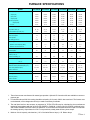
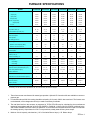
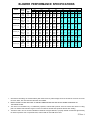
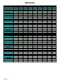
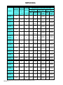
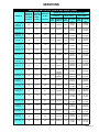
FURNACE SPECIFICATIONS
MODEL
Btuh Input (US)
GUC045B30A
GUC045B30B
GUC070B30A
GUC070B30B
GUC070B40A
GUC070B40B
GUC090B35A
GUC090B35B
GUC090B50A
GUC090B50B
GUC115B50A
GUC115B50B
45,000
70,000
70,000
90,000
90,000
115,000
Output (US)
43,000
65,000
65,000
83,000
84,000
107,000
Input (CAN)
45,000
70,000
70,000
90,000
90,000
115,000
Output (CAN)
43,400
66,400
66,400
85,700
85,700
107,500
High Alt Input (CAN)
Output (CAN)
A.F.U.E.
40,500
63,000
63,000
81,000
81,000
103,500
39,100
59,800
59,800
77,100
77,100
96,800
93.0%
91.1%
91.1%
92.0%
92.0%
91.7%
Rated External Static ("w.c.)
.10 - .50
.12 - .50
.12 - .50
.15 - .50
.15 - .50
.20 - .50
Temperature Rise (°F)
35 - 65
35 - 65
35 - 65
45 - 75
35 - 65
35 - 65
Pressure Switch Trip Point ("w.c)
-1.05
-0.90
-0.90
-1.20
-1.20
-0.65
Blower Wheel (D" x W")
10 x 8
10 x 8
10 x 8
10 x 8
10 x 10
10 x 10
Blower Horsepower
1/3
1/3
3/4
1/2
3/4
3/4
Blower Speeds
3
4
4
4
4
4
Max CFM @ 0.5 E.S.P.
Power Supply
Minimum Circuit Ampacity (MCA)
Maximum Overcurrent Device
1295
1270
1650
1400
2000
2000
115-60-1
115-60-1
115-60-1
115-60-1
115-60-1
115-60-1
12.1
11.1
14.9
12.6
15.1
15.1
15
15
15
15
20
20
Transformer (VA)
40
40
40
40
40
40
Heat Anticipator
0.8
0.8
0.8
0.8
0.8
0.8
Primary Limit Setting (°F)
250
230
230
250
230
180
-
-
-
-
-
-
Auxiliary Limit (°F)
Rollout Limit Setting (°F)
350
350
350
350
350
350
Fan Switch Setting
On (°F)
125
125
125
125
125
125
Off (°F)
110
110
110
110
110
110
Gas Supply Pressure (Natural/Propane) ("w.c.)
Manifold Pressure (Natural/Propane) ("w.c.)
Orifice Size (Natural/Propane)
Number of Burners
Vent Connector Diameter (inches)
7 / 11
7 / 11
7 / 11
7 / 11
7 / 11
7 / 11
3.5 / 10
3.5 / 10
3.5 / 10
3.5 / 10
3.5 / 10
3.5 / 10
#43 / #54
#43 / #54
#43 / #54
#43 / #54
#43 / #54
#43 / #54
2
3
3
4
4
5
2
2
2
2
2
2
Permanent
Permanent
Permanent
Permanent
Permanent
Permanent
Filter Size (inches)
16x25x1
16x25x1
16x25x1
16x25x1
16x25x1
16x25x1
Number of Filters
1
1
1
1
2
2
162
177
185
201
210
235
Filter Type
Shipping Weight (lbs.)
1. These furnaces are manufactured for natural gas operation. Optional LP Conversion Kits are available to convert to
propane gas.
2. For elevations above 2000 ft. the rating should be reduced by 4% for each 1000 ft. above sea level. The furnace must
not be derated, orifice changes should only be made if necessary for altitude.
3. The total heat loss from the structure as expressed in TOTAL BTU/HR must be calculated by the manufacturers
method of in accordance with the "A.S.H.R.A.E. GUIDE" or "MANUAL J-LOAD CALCULATIONS" published by the
AIR CONDITIONING CONTRACTORS OF AMERICA. The total heat loss calculated should be equal to or less than
the heating capacity. Output based on D.O.E. test procedures, steady state efficiency times output.
4. Minimum Circuit Ampacity calculated as: (1.25 x Circulation Blower Amps) + I.D. Blower Amps.
17 Rev. 3
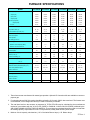
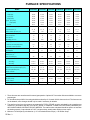
FURNACE SPECIFICATIONS
MODEL
Btuh Input (US)
Output (US)
GUC045B30C
GUC070B30C
GUC070B40C
GUC090B35C
GUC090B50C
GUC115B50C
45,000
70,000
70,000
90,000
90,000
115,000
43,000
65,000
65,000
83,000
84,000
107,000
Input (CAN)
45,000
70,000
70,000
90,000
90,000
115,000
Output (CAN)
43,400
66,400
66,400
85,700
85,700
107,500
High Alt Input (CAN)
40,500
63,000
63,000
81,000
81,000
103,500
39,100
59,800
59,800
77,100
77,100
96,800
Output (CAN)
93.0%
91.1%
91.1%
92.0%
92.0%
91.7%
Rated External Static ("w.c.)
A.F.U.E.
.10 - .50
.12 - .50
.12 - .50
.15 - .50
.15 - .50
.20 - .50
Temperature Rise (°F)
25 - 55
35 - 65
35 - 65
35 - 65
35 - 65
35 - 65
Pressure Switch Trip Point ("w.c)
-1.20
-1.05
-1.05
-1.20
-1.20
-0.75
Blower Wheel (D" x W")
10 x 8
10 x 8
10 x 10
10 x 8
10 x 10
10 x 10
Blower Horsepower
1/3
1/3
3/4
1/2
3/4
3/4
Blower Speeds
3
4
4
4
4
4
Max CFM @ 0.5 E.S.P.
Power Supply
Minimum Circuit Ampacity (MCA)
Maximum Overcurrent Device
1295
1270
1650
1590
2000
2000
115-60-1
115-60-1
115-60-1
115-60-1
115-60-1
115-60-1
12.1
11.1
14.9
12.6
15.1
15.1
15
15
15
15
20
20
Transformer (VA)
40
40
40
40
40
40
Heat Anticipator
0.8
0.8
0.8
0.8
0.8
0.8
Primary Limit Setting (°F)
200
230
230
230
230
180
-
-
-
-
-
-
Auxiliary Limit (°F)
Rollout Limit Setting (°F)
350
350
350
350
350
350
Fan Switch Setting
On (°F)
125
125
125
125
125
125
Off (°F)
110
110
110
110
110
110
Gas Supply Pressure (Natural/Propane) (" w.c.)
Manifold Pressure (Natural/Propane) (" w.c.)
Orifice Size (Natural/Propane)
Number of Burners
Vent Connector Diameter (inches)
7 / 11
7 / 11
7 / 11
7 / 11
7 / 11
7 / 11
3.5 / 10
3.5 / 10
3.5 / 10
3.5 / 10
3.5 / 10
3.5 / 10
#43 / #54
#43 / #54
#43 / #54
#43 / #54
#43 / #54
#43 / #54
2
3
3
4
4
5
2
2
2
2
2
2
Permanent
Permanent
Permanent
Permanent
Permanent
Permanent
Filter Size (inches)
16x25x1
16x25x1
16x25x1
16x25x1
16x25x1
16x25x1
Number of Filters
1
1
1
1
2
2
162
177
185
201
210
235
Filter Type
Shipping Weight (lbs.)
1. These furnaces are manufactured for natural gas operation. Optional LP Conversion Kits are available to convert to
propane gas.
2. For elevations above 2000 ft. the rating should be reduced by 4% for each 1000 ft. above sea level. The furnace must
not be derated, orifice changes should only be made if necessary for altitude.
3. The total heat loss from the structure as expressed in TOTAL BTU/HR must be calculated by the manufacturers
method of in accordance with the "A.S.H.R.A.E. GUIDE" or "MANUAL J-LOAD CALCULATIONS" published by the
AIR CONDITIONING CONTRACTORS OF AMERICA. The total heat loss calculated should be equal to or less than
the heating capacity. Output based on D.O.E. test procedures, steady state efficiency times output.
4. Minimum Circuit Ampacity calculated as: (1.25 x Circulation Blower Amps) + I.D. Blower Amps.
18 Rev. 3
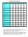
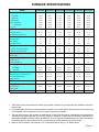
FURNACE SPECIFICATIONS
MODEL
Btuh Input (US)
Output (US)
GUC045C30C
GUC045X30A
GUC070C30C
GUC070X30A
GUC070C40C
GUC070X40A
GUC090C35C
GUC090X35A
GUC090C50C
GUC090X50A
GUC115C50C
GUC115X50A
45,000
70,000
70,000
90,000
90,000
115,000
43,000
65,000
65,000
83,000
84,000
107,000
Input (CAN)
45,000
70,000
70,000
90,000
90,000
115,000
Output (CAN)
43,400
66,400
66,400
85,700
85,700
107,500
High Alt Input (CAN)
40,500
63,000
63,000
81,000
81,000
103,500
39,100
59,800
59,800
77,100
77,100
96,800
Output (CAN)
91.3%
90.1%
90.1%
90.8%
91.1%
90.7%
Rated External Static ("w.c.)
A.F.U.E.
.10 - .50
.12 - .50
.12 - .50
.15 - .50
.15 - .50
.20 - .50
Temperature Rise (°F)
25 - 55
35 - 65
35 - 65
35 - 65
35 - 65
35 - 65
Pressure Switch Trip Point ("w.c)
-1.20
-1.05
-1.05
-1.20
-1.20
-0.75
Blower Wheel (D" x W")
10 x 8
10 x 8
10 x 10
10 x 8
10 x 10
10 x 10
Blower Horsepower
1/3
1/3
3/4
1/2
3/4
3/4
Blower Speeds
3
4
4
4
4
4
Max CFM @ 0.5 E.S.P.
Power Supply
Minimum Circuit Ampacity (MCA)
Maximum Overcurrent Device
1295
1270
1650
1590
2000
2000
115-60-1
115-60-1
115-60-1
115-60-1
115-60-1
115-60-1
12.1
11.1
14.9
12.6
15.1
15.1
15
15
15
15
20
20
Transformer (VA)
40
40
40
40
40
40
Heat Anticipator
0.7
0.7
0.7
0.7
0.7
0.7
Primary Limit Setting (°F)
180
180
170
170
150
140
-
-
-
-
-
-
Auxiliary Limit (°F)
Rollout Limit Setting (°F)
350
350
350
350
350
350
30 secs.
30 secs.
30 secs.
30 secs.
30 secs.
30 secs.
Off Heating*
90 secs.
90 secs.
90 secs.
90 secs.
90 secs.
90 secs.
Off Cooling
45 secs.
45 secs.
45 secs.
45 secs.
45 secs.
45 secs.
7 / 11
7 / 11
7 / 11
7 / 11
7 / 11
7 / 11
Fan Delay ON
Gas Supply Pressure (Natural/Propane) (" w.c.)
Manifold Pressure (Natural/Propane) (" w.c.)
3.5 / 10
3.5 / 10
3.5 / 10
3.5 / 10
3.5 / 10
3.5 / 10
#43 / #54
#43 / #54
#43 / #54
#43 / #54
#43 / #54
#43 / #54
Number of Burners
2
3
3
4
4
5
Vent Connector Diameter (inches)
2
2
2
2
2
2
Permanent
Permanent
Permanent
Permanent
Permanent
Permanent
16x25x1
16x25x1
16x25x1
16x25x1
16x25x1
16x25x1
Orifice Size (Natural/Propane)
Filter Type
Filter Size (inches)
Number of Filters
Shipping Weight (lbs.)
1
1
1
1
2
2
162
177
185
201
210
235
* Off Heating - This fan delay timing is adjustable (60, 90, 120 or 180 seconds), 90 seconds as shipped.
1. These furnaces are manufactured for natural gas operation. Optional LP Conversion Kits are available to convert to
propane gas.
2. For elevations above 2000 ft. the rating should be reduced by 4% for each 1000 ft. above sea level. The furnace must
not be derated, orifice changes should only be made if necessary for altitude.
3. The total heat loss from the structure as expressed in TOTAL BTU/HR must be calculated by the manufacturers
method of in accordance with the "A.S.H.R.A.E. GUIDE" or "MANUAL J-LOAD CALCULATIONS" published by the
AIR CONDITIONING CONTRACTORS OF AMERICA. The total heat loss calculated should be equal to or less than
the heating capacity. Output based on D.O.E. test procedures, steady state efficiency times output.
4. Minimum Circuit Ampacity calculated as: (1.25 x Circulation Blower Amps) + I.D. Blower Amps.
19 Rev. 3
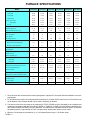
FURNACE SPECIFICATIONS
MODEL
Btuh Input (US)
Output (US)
GUC045X30B
GUC070X30B
GUC070X40B
GUC090X35B
GUC090X50B
GUC115X50B
45,000
70,000
70,000
90,000
90,000
115,000
42,900
65,300
65,300
85,000
85,000
107,800
Input (CAN)
45,000
70,000
70,000
90,000
90,000
115,000
Output (CAN)
43,400
66,400
66,400
85,700
85,700
107,500
High Alt Input (CAN)
40,500
63,000
63,000
81,000
81,000
103,500
39,100
59,800
59,800
77,100
77,100
96,800
Output (CAN)
95.3%
93.3%
93.3%
94.4%
94.4%
93.7%
Rated External Static ("w.c.)
A.F.U.E.
.10 - .50
.12 - .50
.12 - .50
.15 - .50
.15 - .50
.20 - .50
Temperature Rise (°F)
25 - 55
35 - 65
35 - 65
35 - 65
35 - 65
35 - 65
Pressure Switch Trip Point ("w.c)
-1.35
-1.25
-1.25
-1.35
-1.35
-1.05
Blower Wheel (D" x W")
10 x 8
10 x 8
10 x 10
10 x 8
10 x 10
10 x 10
Blower Horsepower
1/3
1/3
3/4
1/2
3/4
3/4
Blower Speeds
3
4
4
4
4
4
Max CFM @ 0.5 E.S.P.
Power Supply
Minimum Circuit Ampacity (MCA)
Maximum Overcurrent Device
1197
1274
1633
1599
1961
1939
115-60-1
115-60-1
115-60-1
115-60-1
115-60-1
115-60-1
12.1
11.1
14.9
12.6
15.1
15.1
15
15
15
15
20
20
Transformer (VA)
40
40
40
40
40
40
Heat Anticipator
0.7
0.7
0.7
0.7
0.7
0.7
Primary Limit Setting (°F)
160
160
170
170
140
125
-
-
-
-
-
-
350
350
350
350
350
350
Auxiliary Limit (°F)
Rollout Limit Setting (°F)
Fan Delay ON
30 secs.
30 secs.
30 secs.
30 secs.
30 secs.
30 secs.
Off Heating *
90 secs.
90 secs.
90 secs.
90 secs.
90 secs.
90 secs.
Off Cooling
45 secs.
45 secs.
45 secs.
45 secs.
45 secs.
45 secs.
Gas Supply Pressure (Natural/Propane) (" w.c.)
Manifold Pressure (Natural/Propane) (" w.c.)
Orifice Size (Natural/Propane)
Number of Burners
Vent Connector Diameter (inches)
7 / 11
7 / 11
7 / 11
7 / 11
7 / 11
7 / 11
3.5 / 10
3.5 / 10
3.5 / 10
3.5 / 10
3.5 / 10
3.5 / 10
#43 / #55
#43 / #55
#43 / #55
#43 / #55
#43 / #55
#43 / #55
2
3
3
4
4
5
2
2
2
2
2
2
Permanent
Permanent
Permanent
Permanent
Permanent
Permanent
Filter Size (inches)
16x25x1
16x25x1
16x25x1
16x25x1
16x25x1
16x25x1
Number of Filters
1
1
1
1
2
2
162
177
185
201
210
235
Filter Type
Shipping Weight (lbs.)
* Off Heating - This fan delay timing is adjustable (60, 90, 120 or 180 seconds), 90 seconds as shipped.
1. These furnaces are manufactured for natural gas operation. Optional LP Conversion Kits are available to convert to
propane gas.
2. For elevations above 2000 ft. the rating should be reduced by 4% for each 1000 ft. above sea level. The furnace must
not be derated, orifice changes should only be made if necessary for altitude.
3. The total heat loss from the structure as expressed in TOTAL BTU/HR must be calculated by the manufacturers
method of in accordance with the "A.S.H.R.A.E. GUIDE" or "MANUAL J-LOAD CALCULATIONS" published by the
AIR CONDITIONING CONTRACTORS OF AMERICA. The total heat loss calculated should be equal to or less than
the heating capacity. Output based on D.O.E. test procedures, steady state efficiency times output.
4. Minimum Circuit Ampacity calculated as: (1.25 x Circulation Blower Amps) + I.D. Blower Amps.
20 Rev. 3
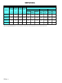
FURNACE SPECIFICATIONS
MODEL
Btuh Input (US)
GCC045B30A
GCC045B30B
GCC070B30A
GCC070B30B
GCC070B40A
GCC070B40B
GCC090B40A
GCC090B40B
GCC090B50A
GCC090B50B
GCC115B50A
GCC115B50B
45,000
70,000
70,000
90,000
90,000
115,000
Output (US)
42,000
65,000
65,000
84,000
84,000
106,000
Input (CAN)
45,000
70,000
70,000
90,000
90,000
115,000
Output (CAN)
42,000
65,000
66,000
85,000
85,000
108,000
High Alt Input (CAN)
Output (CAN)
A.F.U.E.
40,500
63,000
63,000
81,000
81,000
103,500
38,000
59,000
59,000
76,000
76,000
97,000
89.4%
91.1%
91.6%
92.3%
92.3%
91.0%
Rated External Static ("w.c.)
.10 - .50
.12 - .50
.12 - .50
.15 - .50
.15 - .50
.20 - .50
Temperature Rise (°F)
25 - 55
35 - 65
25 - 55
35 - 65
35 - 65
40 - 70
Pressure Switch Trip Point ("w.c)
-0.90
-0.75
-0.75
-0.90
-0.90
-0.40
Blower Wheel (D" x W")
10 x 8
10 x 8
11 x 10
11 x 10
11 x 8
11 x 8
Blower Horsepower
1/3
1/3
1/2
1/2
3/4
3/4
Blower Speeds
3
4
4
4
4
4
Max CFM @ 0.5 E.S.P.
Power Supply
Minimum Circuit Ampacity (MCA)
Maximum Overcurrent Device
1300
1300
1750
1800
2115
2085
115-60-1
115-60-1
115-60-1
115-60-1
115-60-1
115-60-1
12.1
11.1
14.9
12.6
15.1
15.1
15
15
15
15
20
20
Transformer (VA)
40
40
40
40
40
40
Heat Anticipator
0.8
0.8
0.8
0.8
0.8
0.8
Primary Limit Setting (°F)
230
230
230
230
230
230
Auxiliary Limit (°F)
160
160
160
160
160
160
Rollout Limit Setting (°F)
325
325
325
325
325
325
Fan Switch Setting
On (°F)
125
125
125
125
125
125
Off (°F)
110
110
110
110
110
110
Gas Supply Pressure (Natural/Propane) ("w.c.)
Manifold Pressure (Natural/Propane) ("w.c.)
Orifice Size (Natural/Propane)
7 / 11
7 / 11
7 / 11
7 / 11
7 / 11
7 / 11
3.5 / 10
3.5 / 10
3.5 / 10
3.5 / 10
3.5 / 10
3.5 / 10
#43 / #54
#43 / #54
#43 / #54
#43 / #54
#43 / #54
#43 / #54
Number of Burners
2
3
3
4
4
5
Vent Connector Diameter (inches)
2
2
2
2
2
2
Filter Type
-
-
-
-
-
-
Filter Size (inches)
-
-
-
-
-
-
Number of Filters
-
-
-
-
-
-
153
178
178
196
196
210
Shipping Weight (lbs.)
1. These furnaces are manufactured for natural gas operation. Optional LP Conversion Kits are available to convert to
propane gas.
2. For elevations above 2000 ft. the rating should be reduced by 4% for each 1000 ft. above sea level. The furnace must
not be derated, orifice changes should only be made if necessary for altitude.
3. The total heat loss from the structure as expressed in TOTAL BTU/HR must be calculated by the manufacturers
method of in accordance with the "A.S.H.R.A.E. GUIDE" or "MANUAL J-LOAD CALCULATIONS" published by the
AIR CONDITIONING CONTRACTORS OF AMERICA. The total heat loss calculated should be equal to or less than
the heating capacity. Output based on D.O.E. test procedures, steady state efficiency times output.
4. Minimum Circuit Ampacity calculated as: (1.25 x Circulation Blower Amps) + I.D. Blower Amps.
21 Rev. 3
FURNACE SPECIFICATIONS
MODEL
Btuh Input (US)
Output (US)
GCC045C30C
GCC045X30A
GCC070C30C
GCC070X30A
GCC070C40C
GCC070X40A
GCC090C35C
GCC090X35A
GCC090C50C
GCC090X50A
GCC115C50C
GCC115X50A
45,000
70,000
70,000
90,000
90,000
115,000
43,000
65,000
66,000
84,000
84,000
105,000
Input (CAN)
45,000
70,000
70,000
90,000
90,000
115,000
Output (CAN)
43,000
67,000
67,000
86,000
86,000
108,000
High Alt Input (CAN)
40,500
63,000
63,000
81,000
81,000
103,500
38,700
60,300
60,300
77,400
77,400
97,000
Output (CAN)
94.0%
91.5%
92.7%
92.1%
92.1%
90.7%
Rated External Static ("w.c.)
A.F.U.E.
.10 - .50
.12 - .50
.12 - .50
.15 - .50
.15 - .50
.20 - .50
Temperature Rise (°F)
25 - 55
35 - 65
25 - 55
35 - 65
35 - 65
40 - 70
Pressure Switch Trip Point ("w.c)
-1.20
-1.05
-1.05
-1.20
-1.20
-0.75
Blower Wheel (D" x W")
10 x 8
10 x 8
11 x 10
11 x 10
11 x 10
11 x 10
Blower Horsepower
1/3
1/3
1/2
1/2
3/4
3/4
Blower Speeds
3
4
4
4
4
4
Max CFM @ 0.5 E.S.P.
Power Supply
Minimum Circuit Ampacity (MCA)
Maximum Overcurrent Device
1300
1300
1750
1800
2115
2085
115-60-1
115-60-1
115-60-1
115-60-1
115-60-1
115-60-1
12.1
11.1
14.9
12.6
15.1
15.1
15
15
15
15
20
20
Transformer (VA)
40
40
40
40
40
40
Heat Anticipator
0.7
0.7
0.7
0.7
0.7
0.7
Primary Limit Setting (°F)
210
210
200
200
200
190
Auxiliary Limit (°F)
160
160
160
160
160
160
Rollout Limit Setting (°F)
325
325
325
325
325
325
30 secs.
30 secs.
30 secs.
30 secs.
30 secs.
30 secs.
Off Heating*
90 secs.
90 secs.
90 secs.
90 secs.
90 secs.
90 secs.
Off Cooling
45 secs.
45 secs.
45 secs.
45 secs.
45 secs.
45 secs.
7 / 11
7 / 11
7 / 11
7 / 11
7 / 11
7 / 11
Fan Delay ON
Gas Supply Pressure (Natural/Propane) ("w.c.)
Manifold Pressure (Natural/Propane) ("w.c.)
3.5 / 10
3.5 / 10
3.5 / 10
3.5 / 10
3.5 / 10
3.5 / 10
#43 / #54
#43 / #54
#43 / #54
#43 / #54
#43 / #54
#43 / #54
Number of Burners
2
3
3
4
4
5
Vent Connector Diameter (inches)
2
2
2
2
2
2
Filter Type
-
-
-
-
-
-
Filter Size (inches)
-
-
-
-
-
-
Orifice Size (Natural/Propane)
Number of Filters
Shipping Weight (lbs.)
-
-
-
-
-
-
141
165
165
180
180
192
* Off Heating - This fan delay timing is adjustable (60, 90, 120 or 180 seconds), 90 seconds as shipped.
1. These furnaces are manufactured for natural gas operation. Optional LP Conversion Kits are available to convert to
propane gas.
2. For elevations above 2000 ft. the rating should be reduced by 4% for each 1000 ft. above sea level. The furnace must
not be derated, orifice changes should only be made if necessary for altitude.
3. The total heat loss from the structure as expressed in TOTAL BTU/HR must be calculated by the manufacturers
method of in accordance with the "A.S.H.R.A.E. GUIDE" or "MANUAL J-LOAD CALCULATIONS" published by the
AIR CONDITIONING CONTRACTORS OF AMERICA. The total heat loss calculated should be equal to or less than
the heating capacity. Output based on D.O.E. test procedures, steady state efficiency times output.
4. Minimum Circuit Ampacity calculated as: (1.25 x Circulation Blower Amps) + I.D. Blower Amps.
22 Rev. 3
FURNACE SPECIFICATIONS
MODEL
Btuh Input (US)
Output (US)
GUD045B30A
GUD070B30A
GUD070B40A
GUD090B35A
GUD090B50A
GUD115B50A
45,000
70,000
70,000
90,000
90,000
115,000
43,000
65,000
65,000
83,000
84,000
107,000
Input (CAN)
45,000
70,000
70,000
90,000
90,000
115,000
Output (CAN)
43,400
66,400
66,400
85,700
85,700
107,500
High Alt Input (CAN)
40,500
63,000
63,000
81,000
81,000
103,500
39,100
59,800
59,800
77,100
77,100
98,800
Output (CAN)
94.8%
93.2%
93.2%
92.7%
92.5%
91.8%
Rated External Static ("w.c.)
A.F.U.E.
.10 - .50
.12 - .50
.12 - .50
.15 - .50
.15 - .50
.20 - .50
Temperature Rise (°F)
25 - 55
35 - 65
35 - 65
45 - 75
35 - 65
35 - 65
Pressure Switch Trip Point ("w.c)
-1.20
-0.90
-0.90
-1.20
-1.20
-0.70
Blower Wheel (D" x W")
10 x 8
10 x 8
10 x 10
10 x 8
10 x 10
10 x 10
Blower Horsepower
1/3
1/3
3/4
1/2
3/4
3/4
Blower Speeds
3
4
4
4
4
4
Max CFM @ 0.5 E.S.P.
Power Supply
Minimum Circuit Ampacity (MCA)
Maximum Overcurrent Device
1295
1270
1650
1400
2000
2000
115-60-1
115-60-1
115-60-1
115-60-1
115-60-1
115-60-1
11.3
10.3
14.1
10.1
15.1
15.1
15
15
15
15
20
20
Transformer (VA)
40
40
40
40
40
40
Heat Anticipator
0.7
0.7
0.7
0.7
0.7
0.7
Primary Limit Setting (°F)
210
180
180
160
160
150
-
-
-
-
-
-
275
275
275
275
275
275
Auxiliary Limit (°F)
Rollout Limit Setting (°F)
Fan Delay ON
30 secs.
30 secs.
30 secs.
30 secs.
30 secs.
30 secs.
Off Heating *
90 secs.
90 secs.
90 secs.
90 secs.
90 secs.
90 secs.
Off Cooling
45 secs.
45 secs.
45 secs.
45 secs.
45 secs.
45 secs.
7 / 11
7 / 11
7 / 11
7 / 11
7 / 11
7 / 11
Gas Supply Pressure (Natural/Propane) ("w.c.)
Manifold Pressure (Natural/Propane) ("w.c.)
3.5 / 10
3.5 / 10
3.5 / 10
3.5 / 10
3.5 / 10
3.5 / 10
Orifice Size (Natural/Propane)
#43 / NA
#43 / NA
#43 / NA
#43 / NA
#43 / NA
#43 / NA
Number of Burners
2
3
3
4
4
5
Vent Connector Diameter (inches)
2
2
2
2
2
2
Combustion Air Connector Diameter (inches)
3
3
3
3
3
3
Permanent
Permanent
Permanent
Permanent
Permanent
Permanent
Filter Size (inches)
16x25x1
16x25x1
16x25x1
16x25x1
16x25x1
16x25x1
Number of Filters
1
1
1
1
2
2
158
194
194
216
216
231
Filter Type
Shipping Weight (lbs.)
* Off Heating - This fan delay timing is adjustable (60, 90, 120 or 180 seconds), 90 seconds as shipped.
1. These furnaces are manufactured for natural gas operation. Optional LP Conversion Kits are available to convert to
propane gas. Note: GUD___B__A models cannot be converted to use propane gas.
2. For elevations above 2000 ft. the rating should be reduced by 4% for each 1000 ft. above sea level. The furnace must
not be derated, orifice changes should only be made if necessary for altitude.
3. The total heat loss from the structure as expressed in TOTAL BTU/HR must be calculated by the manufacturers
method of in accordance with the "A.S.H.R.A.E. GUIDE" or "MANUAL J-LOAD CALCULATIONS" published by the
AIR CONDITIONING CONTRACTORS OF AMERICA. The total heat loss calculated should be equal to or less than
the heating capacity. Output based on D.O.E. test procedures, steady state efficiency times output.
4. Minimum Circuit Ampacity calculated as: (1.25 x Circulation Blower Amps) + I.D. Blower Amps.
23 Rev. 3
FURNACE SPECIFICATIONS
MODEL
Btuh Input (US)
GUD045C30A
GUD045X30A
GUD070C30A
GUD070X30A
GUD070C40A
GUD070X40A
GUD090C35A
GUD090X35A
GUD090C50A
GUD090X50A
GUD115C50A
GUD115X50A
115,000
45,000
70,000
70,000
90,000
90,000
Output (US)
43,000
65,000
65,000
84,000
84,000
107,000
Input (CAN)
45,000
70,000
70,000
90,000
90,000
115,000
Output (CAN)
43,700
66,400
66,400
85,500
85,500
109,700
High Alt Input (CAN)
40,500
63,000
63,000
81,000
81,000
103,500
39,300
59,800
59,800
77,000
77,000
98,700
94.8%
93.2%
93.2%
92.7%
92.5%
91.8%
Rated External Static ("w.c.)
.10 - .50
.12 - .50
.12 - .50
.15 - .50
.15 - .50
.20 - .50
Temperature Rise (°F)
25 - 55
35 - 65
35 - 65
45 - 75
35 - 65
35 - 65
Pressure Switch Trip Point ("w.c)
-1.20
-0.90
-0.90
-1.20
-1.20
-0.80
Blower Wheel (D" x W")
10 x 8
10 x 8
10 x 10
10 x 8
10 x 10
10 x 10
1/3
1/3
3/4
1/2
3/4
3/4
Output (CAN)
A.F.U.E.
Blower Horsepower
Blower Speeds
Max CFM @ 0.5 E.S.P.
Power Supply
Minimum Circuit Ampacity (MCA)
Maximum Overcurrent Device
3
4
4
4
4
4
1295
1270
1650
1400
2000
2000
115-60-1
115-60-1
115-60-1
115-60-1
115-60-1
115-60-1
11.3
10.3
14.1
10.1
15.1
15.1
15
15
15
15
20
20
Transformer (VA)
40
40
40
40
40
40
Heat Anticipator
0.7
0.7
0.7
0.7
0.7
0.7
Primary Limit Setting (°F)
210
180
180
160
160
150
-
-
-
-
-
-
Auxiliary Limit (°F)
Rollout Limit Setting (°F)
275
275
275
275
275
275
30 secs.
30 secs.
30 secs.
30 secs.
30 secs.
30 secs.
Off Heating*
90 secs.
90 secs.
90 secs.
90 secs.
90 secs.
90 secs.
Off Cooling
45 secs.
45 secs.
45 secs.
45 secs.
45 secs.
45 secs.
7 / 11
7 / 11
7 / 11
7 / 11
7 / 11
7 / 11
Fan Delay ON
Gas Supply Pressure (Natural/Propane) ("w.c.)
Manifold Pressure (Natural/Propane) ("w.c.)
Orifice Size (Natural/Propane)
3.5 / 10
3.5 / 10
3.5 / 10
3.5 / 10
3.5 / 10
3.5 / 10
#43 / #54
#43 / #54
#43 / #54
#43 / #54
#43 / #54
#43 / #54
Number of Burners
2
3
3
4
4
5
Vent Connector Diameter (inches)
2
2
2
2
2
2
Combustion Air Connector Diameter (inches)
3
3
3
3
3
3
Permanent
Permanent
Permanent
Permanent
Permanent
Permanent
16x25x1
16x25x1
16x25x1
16x25x1
16x25x1
16x25x1
Filter Type
Filter Size (inches)
Number of Filters
Shipping Weight (lbs.)
1
1
1
1
2
2
158
194
194
216
216
231
* Off Heating - This fan delay timing is adjustable (60, 90, 120 or 180 seconds), 90 seconds as shipped.
1. These furnaces are manufactured for natural gas operation. Optional LP Conversion Kits are available to convert to
propane gas.
2. For elevations above 2000 ft. the rating should be reduced by 4% for each 1000 ft. above sea level. The furnace must
not be derated, orifice changes should only be made if necessary for altitude.
3. The total heat loss from the structure as expressed in TOTAL BTU/HR must be calculated by the manufacturers
method of in accordance with the "A.S.H.R.A.E. GUIDE" or "MANUAL J-LOAD CALCULATIONS" published by the
AIR CONDITIONING CONTRACTORS OF AMERICA. The total heat loss calculated should be equal to or less than
the heating capacity. Output based on D.O.E. test procedures, steady state efficiency times output.
4. Minimum Circuit Ampacity calculated as: (1.25 x Circulation Blower Amps) + I.D. Blower Amps.
24 Rev. 3
FURNACE SPECIFICATIONS
MODEL
Btuh Input (US)
Output (US)
GUD045X30B
GUD070X30B
GUD070X40B
GUD090X35B
GUD090X50B
GUD115X50B
45,000
70,000
70,000
90,000
90,000
115,000
43,000
65,700
65,700
84,300
85,100
107,600
Input (CAN)
45,000
70,000
70,000
90,000
90,000
115,000
Output (CAN)
43,000
65,700
65,700
85,000
85,100
107,600
High Alt Input (CAN)
40,500
63,000
63,000
81,000
81,000
103,500
38,700
59,100
59,100
76,600
76,600
96,900
Output (CAN)
95.6%
93.8%
93.8%
94.6%
94.6%
93.6%
Rated External Static ("w.c.)
A.F.U.E.
.10 - .50
.12 - .50
.12 - .50
.15 - .50
.15 - .50
.20 - .50
Temperature Rise (°F)
25 - 55
35 - 65
35 - 65
45 - 75
35 - 65
35 - 65
Pressure Switch Trip Point ("w.c)
-1.38
-1.38
-1.38
-1.57
-1.57
-1.38
Blower Wheel (D" x W")
10 x 8
10 x 8
10 x 10
10 x 8
10 x 10
10 x 10
Blower Horsepower
1/3
1/3
3/4
1/2
3/4
3/4
Blower Speeds
3
4
4
4
4
4
Max CFM @ 0.5 E.S.P.
Power Supply
Minimum Circuit Ampacity (MCA)
Maximum Overcurrent Device
1131
1188
1561
1395
1914
1896
115-60-1
115-60-1
115-60-1
115-60-1
115-60-1
115-60-1
11.3
10.3
14.1
10.1
15.1
15.1
15
15
15
15
20
20
Transformer (VA)
40
40
40
40
40
40
Heat Anticipator
0.7
0.7
0.7
0.7
0.7
0.7
Primary Limit Setting (°F)
170
180
180
160
160
140
-
-
-
-
-
-
275
275
275
275
275
275
Auxiliary Limit (°F)
Rollout Limit Setting (°F)
Fan Delay ON
30 secs.
30 secs.
30 secs.
30 secs.
30 secs.
30 secs.
Off Heating *
90 secs.
90 secs.
90 secs.
90 secs.
90 secs.
90 secs.
Off Cooling
45 secs.
45 secs.
45 secs.
45 secs.
45 secs.
45 secs.
7 / 11
7 / 11
7 / 11
7 / 11
7 / 11
7 / 11
Gas Supply Pressure (Natural/Propane) ("w.c.)
Manifold Pressure (Natural/Propane) ("w.c.)
3.5 / 10
3.5 / 10
3.5 / 10
3.5 / 10
3.5 / 10
3.5 / 10
#43 / #55
#43 / #55
#43 / #55
#43 / #55
#43 / #55
#43 / #55
Number of Burners
2
3
3
4
4
5
Vent Connector Diameter (inches)
2
2
2
2
2
2
Orifice Size (Natural/Propane)
Combustion Air Connector Diameter (inches)
3
3
3
3
3
3
Permanent
Permanent
Permanent
Permanent
Permanent
Permanent
Filter Size (inches)
16x25x1
16x25x1
16x25x1
16x25x1
16x25x1
16x25x1
Number of Filters
1
1
1
1
2
2
158
194
194
216
216
231
Filter Type
Shipping Weight (lbs.)
* Off Heating - This fan delay timing is adjustable (60, 90, 120 or 180 seconds), 90 seconds as shipped.
1. These furnaces are manufactured for natural gas operation. Optional LP Conversion Kits are available to convert to
propane gas.
2. For elevations above 2000 ft. the rating should be reduced by 4% for each 1000 ft. above sea level. The furnace must
not be derated, orifice changes should only be made if necessary for altitude.
3. The total heat loss from the structure as expressed in TOTAL BTU/HR must be calculated by the manufacturers
method of in accordance with the "A.S.H.R.A.E. GUIDE" or "MANUAL J-LOAD CALCULATIONS" published by the
AIR CONDITIONING CONTRACTORS OF AMERICA. The total heat loss calculated should be equal to or less than
the heating capacity. Output based on D.O.E. test procedures, steady state efficiency times output.
4. Minimum Circuit Ampacity calculated as: (1.25 x Circulation Blower Amps) + I.D. Blower Amps.
25 Rev. 3
FURNACE SPECIFICATIONS
MODEL
Btuh Input (US)
Output (US)
GUX045B30A
GUX045X30A
GUX070B30A
GUX070X30A
GUX070B40A
GUX070X40A
GUX090B35A
GUX090X35A
GUX090B50A
GUX090X50A
GUX115B50A
GUX115X50A
45,000
70,000
70,000
90,000
90,000
115,000
43,600
67,000
67,000
86,000
87,000
110,000
Input (CAN)
45,000
70,000
70,000
90,000
90,000
115,000
Output (CAN)
43,400
67,600
68,200
87,000
87,300
111,100
High Alt Input (CAN)
40,500
63,000
63,000
81,000
81,000
103,500
39,600
60,800
61,400
78,300
78,600
100,000
Output (CAN)
95.5%
95.3%
95.1%
95.3%
95.5%
95.0%
Rated External Static ("w.c.)
A.F.U.E.
.10 - .50
.12 - .50
.12 - .50
.15 - .50
.15 - .50
.20 - .50
Temperature Rise (°F)
35 - 65
40 - 70
35 - 65
40 - 70
35 - 65
40 - 70
Pressure Switch Trip Point ("w.c)
-1.45
-1.20
-1.20
-1.45
-1.45
-1.20
Blower Wheel (D" x W")
10 x 8
10 x 8
10 x 10
10 x 8
10 x 10
11 x 10
Blower Horsepower
1/3
1/3
3/4
1/2
3/4
3/4
Blower Speeds
3
4
4
4
4
4
Max CFM @ 0.5 E.S.P.
Power Supply
Minimum Circuit Ampacity (MCA)
Maximum Overcurrent Device
1325
1290
1590
1580
1995
2075
115-60-1
115-60-1
115-60-1
115-60-1
115-60-1
115-60-1
12.1
11.1
14.9
12.6
15.1
15.1
15
15
15
15
20
20
Transformer (VA)
40
40
40
40
40
40
Heat Anticipator
0.7
0.7
0.7
0.7
0.7
0.7
Primary Limit Setting (°F)
180
180
170
160
160
140
-
-
-
-
-
-
Auxiliary Limit (°F)
Rollout Limit Setting (°F)
350
350
350
350
350
350
30 secs.
30 secs.
30 secs.
30 secs.
30 secs.
30 secs.
Off Heating*
90 secs.
90 secs.
90 secs.
90 secs.
90 secs.
90 secs.
Off Cooling
45 secs.
45 secs.
45 secs.
45 secs.
45 secs.
45 secs.
7 / 11
7 / 11
7 / 11
7 / 11
7 / 11
7 / 11
Fan Delay ON
Gas Supply Pressure (Natural/Propane) ("w.c.)
Manifold Pressure (Natural/Propane) ("w.c.)
3.5 / 10
3.5 / 10
3.5 / 10
3.5 / 10
3.5 / 10
3.5 / 10
#43 / #54
#43 / #54
#43 / #54
#43 / #54
#43 / #54
#43 / #54
Number of Burners
2
3
3
4
4
5
Vent Connector Diameter (inches)
2
2
2
2
2
2
Permanent
Permanent
Permanent
Permanent
Permanent
Permanent
16x25x1
16x25x1
16x25x1
16x25x1
16x25x1
16x25x1
Orifice Size (Natural/Propane)
Filter Type
Filter Size (inches)
Number of Filters
Shipping Weight (lbs.)
1
1
1
1
2
2
162
177
188
201
210
235
* Off Heating - This fan delay timing is adjustable (60, 90, 120 or 180 seconds), 90 seconds as shipped.
1. These furnaces are manufactured for natural gas operation. Optional LP Conversion Kits are available to convert to
propane gas.
2. For elevations above 2000 ft. the rating should be reduced by 4% for each 1000 ft. above sea level. The furnace must
not be derated, orifice changes should only be made if necessary for altitude.
3. The total heat loss from the structure as expressed in TOTAL BTU/HR must be calculated by the manufacturers
method of in accordance with the "A.S.H.R.A.E. GUIDE" or "MANUAL J-LOAD CALCULATIONS" published by the
AIR CONDITIONING CONTRACTORS OF AMERICA. The total heat loss calculated should be equal to or less than
the heating capacity. Output based on D.O.E. test procedures, steady state efficiency times output.
4. Minimum Circuit Ampacity calculated as: (1.25 x Circulation Blower Amps) + I.D. Blower Amps.
26 Rev. 3
FURNACE SPECIFICATIONS
MODEL
Btuh Input (US)
Output (US)
GUX045X30B
GUX070X30B
GUX070X40B
GUX090X35B
GUX090X50B
GUX115X50B
45,000
70,000
70,000
90,000
90,000
115,000
43,600
67,100
67,100
86,200
86,200
109,600
Input (CAN)
45,000
70,000
70,000
90,000
90,000
115,000
Output (CAN)
43,600
67,100
67,100
86,200
96,200
109,600
High Alt Input (CAN)
40,500
63,000
63,000
81,000
81,000
103,500
39,200
60,400
60,400
77,600
77,600
98,600
Output (CAN)
96.9%
95.9%
95.9%
95.8%
95.8%
95.3%
Rated External Static ("w.c.)
A.F.U.E.
.10 - .50
.12 - .50
.12 - .50
.15 - .50
.15 - .50
.20 - .50
Temperature Rise (°F)
35 - 65
40 - 70
35 - 65
40 - 70
35 - 65
40 - 70
Pressure Switch Trip Point ("w.c)
-1.45
-1.20
-1.20
-1.20
-1.20
-1.20
Blower Wheel (D" x W")
10 x 8
10 x 8
10 x 10
10 x 8
10 x 10
11 x 10
Blower Horsepower
1/3
1/3
3/4
1/2
3/4
3/4
Blower Speeds
3
4
4
4
4
4
Max CFM @ 0.5 E.S.P.
1339
1283
1723
1510
1890
1978
115-60-1
115-60-1
115-60-1
115-60-1
115-60-1
115-60-1
Minimum Circuit Ampacity (MCA)
12.1
11.1
14.9
12.6
15.1
15.1
Maximum Overcurrent Device
15.0
15.0
15.0
15.0
20.0
20.0
Power Supply
Transformer (VA)
40
40
40
40
40
40
Heat Anticipator
0.7
0.7
0.7
0.7
0.7
0.7
Primary Limit Setting (°F)
180
180
170
160
140
125
-
-
-
-
-
-
Auxiliary Limit (°F)
Rollout Limit Setting (°F)
350
350
350
350
350
350
30 secs.
30 secs.
30 secs.
30 secs.
30 secs.
30 secs.
Off Heating *
90 secs.
90 secs.
90 secs.
90 secs.
90 secs.
90 secs.
Off Cooling
45 secs.
45 secs.
45 secs.
45 secs.
45 secs.
45 secs.
7 / 11
7 / 11
7 / 11
7 / 11
7 / 11
7 / 11
Fan Delay ON
Gas Supply Pressure (Natural/Propane) ("w.c.)
Manifold Pressure (Natural/Propane) ("w.c.)
3.5 / 10
3.5 / 10
3.5 / 10
3.5 / 10
3.5 / 10
3.5 / 10
#43 / #55
#43 / #55
#43 / #55
#43 / #55
#43 / #55
#43 / #55
Number of Burners
2
3
3
4
4
5
Vent Connector Diameter (inches)
2
2
2
2
2
2
Permanent
Permanent
Permanent
Permanent
Permanent
Permanent
16x25x1
16x25x1
16x25x1
16x25x1
16x25x1
16x25x1
Orifice Size (Natural/Propane)
Filter Type
Filter Size (inches)
Number of Filter
Shipping Weight (lbs.)
1
1
1
1
2
2
162
177
185
201
210
235
* Off Heating - This fan delay timing is adjustable (60, 90, 120 or 180 seconds), 90 seconds as shipped.
1. These furnaces are manufactured for natural gas operation. Optional LP Conversion Kits are available to convert to
propane gas.
2. For elevations above 2000 ft. the rating should be reduced by 4% for each 1000 ft. above sea level. The furnace must
not be derated, orifice changes should only be made if necessary for altitude.
3. The total heat loss from the structure as expressed in TOTAL BTU/HR must be calculated by the manufacturers
method of in accordance with the "A.S.H.R.A.E. GUIDE" or "MANUAL J-LOAD CALCULATIONS" published by the
AIR CONDITIONING CONTRACTORS OF AMERICA. The total heat loss calculated should be equal to or less than
the heating capacity. Output based on D.O.E. test procedures, steady state efficiency times output.
4. Minimum Circuit Ampacity calculated as: (1.25 x Circulation Blower Amps) + I.D. Blower Amps.
27 Rev. 3
FURNACE SPECIFICATIONS
MODEL
Btuh Input (US)
Output (US)
GDC045X30B
GDC070X30B
GDC070X40B
GDC090X40B
GDC090X50B
GDC115X50B
46,000
69,000
69,000
92,000
92,000
115,000
43,300
65,600
65,500
87,000
87,200
107,700
Input (CAN)
46,000
69,000
69,000
92,000
92,000
115,000
Output (CAN)
43,100
65,000
65,000
86,700
86,700
107,200
High Alt Input (CAN)
41,400
62,100
62,100
82,800
82,800
103,500
38,800
58,500
58,500
78,000
78,000
96,500
Output (CAN)
93.7%
94.2%
94.2%
94.2%
94.2%
93.2%
Rated External Static ("w.c.)
A.F.U.E.
.10 - .50
.12 - .50
.12 - .50
.15 - .50
.15 - .50
.20 - .50
Temperature Rise (°F)
25 - 55
35 - 65
30 - 60
35 - 65
35 - 65
40 - 70
Pressure Switch Trip Point ("w.c)
-1.25
-1.05
-1.05
-1.20
-1.20
-1.05
Blower Wheel (D" x W")
10 x 8
10 x 8
11 x 10
11 x 10
11 x 10
11 x 10
Blower Horsepower
1/3
1/3
1/2
1/2
3/4
3/4
Blower Speeds
3
4
4
4
4
4
Max CFM @ 0.5 E.S.P.
Power Supply
Minimum Circuit Ampacity (MCA)
Maximum Overcurrent Device
1310
1267
1742
1939
2142
2264
115-60-1
115-60-1
115-60-1
115-60-1
115-60-1
115-60-1
12.1
12.1
12
12.1
15.1
15.1
15
15
15
15
20
20
Transformer (VA)
40
40
40
40
40
40
Heat Anticipator
0.7
0.7
0.7
0.7
0.7
0.7
Primary Limit Setting (°F)
200
170
180
170
170
170
Auxiliary Limit (°F)
160
160
160
160
160
160
Rollout Limit Setting (°F)
325
350
350
350
350
350
30 secs.
30 secs.
30 secs.
30 secs.
30 secs.
30 secs.
Off Heating *
90 secs.
90 secs.
90 secs.
90 secs.
90 secs.
90 secs.
Off Cooling
45 secs.
45 secs.
45 secs.
45 secs.
45 secs.
45 secs.
7 / 11
7 / 11
7 / 11
7 / 11
7 / 11
7 / 11
Fan Delay ON
Gas Supply Pressure (Natural/Propane) ("w.c.)
Manifold Pressure (Natural/Propane) ("w.c.)
3.5 / 10
3.5 / 10
3.5 / 10
3.5 / 10
3.5 / 10
3.5 / 10
#43 / #55
#43 / #55
#43 / #55
#43 / #55
#43 / #55
#43 / #55
Number of Burners
2
3
3
4
4
5
Vent Connector Diameter (inches)
2
2
2
2
2
2
Disposable
Disposable
Permanent
Permanent
Permanent
Permanent
15x20x1
15x20x1
16x25x1
16x25x1
16x25x1
16x25x1
Orifice Size (Natural/Propane)
Filter Type
Filter Size (inches)
Number of Filters
Shipping Weight (lbs.)
2
2
2
2
2
2
162
177
185
201
210
235
* Off Heating - This fan delay timing is adjustable (60, 90, 120 or 180 seconds), 90 seconds as shipped.
1. These furnaces are manufactured for natural gas operation. Optional LP Conversion Kits are available to convert to
propane gas.
2. For elevations above 2000 ft. the rating should be reduced by 4% for each 1000 ft. above sea level. The furnace must
not be derated, orifice changes should only be made if necessary for altitude.
3. The total heat loss from the structure as expressed in TOTAL BTU/HR must be calculated by the manufacturers
method of in accordance with the "A.S.H.R.A.E. GUIDE" or "MANUAL J-LOAD CALCULATIONS" published by the
AIR CONDITIONING CONTRACTORS OF AMERICA. The total heat loss calculated should be equal to or less than
the heating capacity. Output based on D.O.E. test procedures, steady state efficiency times output.
4. Minimum Circuit Ampacity calculated as: (1.25 x Circulation Blower Amps) + I.D. Blower Amps.
28 Rev. 3
FURNACE SPECIFICATIONS
MODEL
Btuh Input (US)
Output (US)
GCD070X30B
GCD090X40B
69,000
92,000
64,700
85,900
Input (CAN)
69,000
92,000
Output (CAN)
64,300
86,700
High Alt Input (CAN)
62,100
82,800
58,500
78,000
93.6%
94.0%
Rated External Static ("w.c.)
.12 - .50
.15 - .50
Temperature Rise (°F)
35 - 65
35 - 65
Output (CAN)
A.F.U.E.
Pressure Switch Trip Point ("w.c)
-1.05
-1.30
Blower Wheel (D" x W")
10 x 8
11 x 10
Blower Horsepower
1/3
1/2
Blower Speeds
4
4
Max CFM @ 0.5 E.S.P.
Power Supply
Minimum Circuit Ampacity (MCA)
Maximum Overcurrent Device
1267
1939
115-60-1
115-60-1
12.1
12.1
15
15
Transformer (VA)
40
40
Heat Anticipator
0.7
0.7
Primary Limit Setting (°F)
180
170
Auxiliary Limit (°F)
160
160
Rollout Limit Setting (°F)
275
275
Fan Delay ON
30 secs.
30 secs.
Off Heating *
90 secs.
90 secs.
Off Cooling
45 secs.
45 secs.
7 / 11
7 / 11
Gas Supply Pressure (Natural/Propane) ("w.c.)
Manifold Pressure (Natural/Propane) ("w.c.)
Orifice Size (Natural/Propane)
3.5 / 10
3.5 / 10
#43 / #55
#43 / #55
Number of Burners
3
4
Vent Connector Diameter (inches)
2
2
Filter Type
Disposable
Permanent
Filter Size (inches)
15x20x1
16x25x1
Number of Filters
2
2
177
201
Shipping Weight (lbs.)
* Off Heating - This fan delay timing is adjustable (60, 90, 120 or 180 seconds), 90 seconds as shipped.
1. These furnaces are manufactured for natural gas operation. Optional LP Conversion Kits are available to convert to
propane gas.
2. For elevations above 2000 ft. the rating should be reduced by 4% for each 1000 ft. above sea level. The furnace must
not be derated, orifice changes should only be made if necessary for altitude.
3. The total heat loss from the structure as expressed in TOTAL BTU/HR must be calculated by the manufacturers
method of in accordance with the "A.S.H.R.A.E. GUIDE" or "MANUAL J-LOAD CALCULATIONS" published by the
AIR CONDITIONING CONTRACTORS OF AMERICA. The total heat loss calculated should be equal to or less than
the heating capacity. Output based on D.O.E. test procedures, steady state efficiency times output.
4. Minimum Circuit Ampacity calculated as: (1.25 x Circulation Blower Amps) + I.D. Blower Amps.
29 Rev. 3
BLOWER PERFORMANCE SPECIFICATIONS
MODEL
GUC045_30_
GUC070_30_
GUC070_40_
GUC090B35A
GUC090B35C
GUC090C35C
GUC090X35A
GUC090_50_
GUC115_50_
MODEL
(Htg. Speed
As Shipped)
GUC045X30B
(MED)
GUC070X30B
(HIGH)
GUC070X40B
(LOW)
GUC090X35B
(HIGH)
GUC090X50B
(MED-LO)
GUC115X50B
(HIGH)
MOTOR
SPEED
HIGH
MED
LOW
HIGH
MED
MED-LO
LOW
HIGH
MED
MED-LO
LOW
HIGH
MED
MED-LO
LOW
HIGH
MED
MED-LO
LOW
HIGH
MED
MED-LO
LOW
HIGH
MED
MED-LO
LOW
MOTOR
SPEED
HIGH
MED
LOW
HIGH
MED
MED-LO
LOW
HIGH
MED
MED-LO
LOW
HIGH
MED
MED-LO
LOW
HIGH
MED
MED-LO
LOW
HIGH
MED
MED-LO
LOW
TONS AC
External Static Pressure, Inches Water Column
@ 0.5"
0.2
0.3
0.4
0.5
0.6
0.7
0.8
ESP
CFM Rise CFM Rise CFM Rise CFM Rise CFM Rise CFM Rise CFM Rise
3.0
2.5
2.0
3.0
2.5
2.0
1.5
4.0
3.5
3.5
3.0
4.0
3.5
3.0
2.5
4.0
3.5
3.0
2.5
5.0
4.5
4.0
3.5
5.0
4.5
4.0
3.5
1500
1275
980
1460
1245
1000
820
1855
1680
1525
1350
1610
1440
1165
900
1825
1615
1325
1055
2250
1900
1700
1465
2280
1920
1690
1455
40
42
45
61
36
40
45
49
54
67
41
47
57
41
46
53
44
52
59
-
1440
1200
970
1400
1205
985
800
1785
1615
1480
1325
1560
1400
1150
895
1750
1545
1290
1040
2175
1865
1670
1450
2190
1865
1665
1440
40
44
51
62
38
41
46
50
56
68
43
49
59
36
42
47
54
46
54
60
-
1375
1175
940
1325
1165
960
785
1735
1560
1425
1275
1470
1340
1135
890
1670
1485
1250
1000
2085
1805
1625
1400
2100
1805
1610
1390
42
46
52
63
39
43
48
53
58
69
45
51
61
38
43
48
56
48
55
62
-
1295
1125
900
1270
1115
920
755
1650
1480
1350
1200
1400
1280
1090
875
1590
1425
1195
970
2000
1735
1565
1350
2000
1730
155
1350
44
48
55
37
41
45
51
56
61
72
48
53
63
39
45
50
58
50
58
64
-
1210
1055
865
1180
1050
880
730
1575
1400
1280
1145
1295
1200
1055
840
1500
1345
1145
930
1890
1635
1500
1280
1880
1650
1485
1290
36
44
49
56
37
42
46
51
58
63
72
50
56
40
46
51
59
51
59
-
1120
975
810
1095
980
815
680
1485
1310
1200
1045
1295
1200
1055
840
1400
1260
1080
870
1780
1590
1400
1195
1755
1535
1390
1220
39
47
53
60
39
45
49
56
63
67
54
60
43
48
54
64
55
63
-
1010
870
730
985
880
752
635
1375
1200
1100
800
1080
1020
920
750
1310
1170
990
800
1640
1465
1255
1050
1600
1355
1245
1115
37
43
52
59
42
49
53
70
74
58
46
52
60
60
-
TONS AC
External Static Pressure, Inches Water Column
@ 0.5"
0.1
0.2
0.3
0.4
0.5
0.6
0.7
0.8
ESP
CFM Rise CFM Rise CFM Rise CFM Rise CFM Rise CFM CFM CFM
3.0
2.5
2.0
3.0
2.5
2.0
1.5
4.0
3.5
3.5
3.0
4.0
3.5
3.0
2.5
4.0
3.5
3.0
2.5
5.0
4.5
4.0
3.5
1470
1294
1000
1541
1323
1036
788
1973
1786
1590
1341
1890
1659
1340
1049
2326
1997
1744
1483
2325
1988
1729
1473
26
30
39
39
46
58
38
45
41
47
58
39
44
52
42
49
57
-
1401
1254
999
1509
1274
1024
786
1894
1729
1553
1333
1825
1614
1340
1040
2232
1936
1710
1469
2233
1927
1702
1460
28
31
39
40
47
59
35
39
45
43
48
58
35
40
45
53
44
51
58
-
1337
1207
984
1414
1234
1006
784
1806
1650
1507
1311
1757
1569
1310
1034
2123
1874
1681
1449
2136
1871
1666
1443
29
32
39
43
49
60
37
40
46
44
49
59
37
41
46
54
46
52
59
-
1269
1153
959
1349
1181
978
765
1724
1575
1447
1281
1673
1506
1279
1013
2055
1810
1634
1429
2046
1797
1611
1417
31
34
40
45
51
62
35
38
42
47
46
52
61
38
43
47
54
48
55
61
-
1197
1089
920
1274
1121
940
745
1633
1501
1384
1225
1599
1441
1240
985
1961
1743
1573
1387
1939
1720
1554
1372
32
36
42
47
54
64
37
40
44
49
49
54
63
40
45
49
56
51
57
63
-
1121
962
866
1202
1050
890
698
1536
1410
1311
1133
1506
1372
1182
941
1861
1659
1503
1329
1840
1630
1484
1316
1030
940
785
1108
975
826
639
1422
1268
1142
1033
1424
1281
1103
883
1756
1556
1415
1245
1721
1544
1390
1243
919
819
700
1005
880
720
563
1383
1097
1033
889
1300
1183
1009
803
1616
1429
1292
1085
1593
1422
1277
1128
1. CFM chart is with filter(s) as shipped with furnace. If furnace is shipped with two side air return filters, this chart assumes both
filters are installed.
2. INSTALLATION IS TO BE ADJUSTED TO OBTAIN TEMPERATURE RISE WITHIN THE RANGE SPECIFIED ON THE RATING
PLATE.
3. The chart is for information only. For satisfactory operation, external static pressure must not exceed value shown on rating
plate. The shaded area indicates ranges in excess of maximum external static pressure allowed when heating.
4. The above chart is for U.S. furnaces installed at 0-2000 feet. At higher altitudes, a properly derated unit will have approximately
the same temperature rise at a particular CFM, while the ESP at that CFM will be lower.
30 Rev. 3
BLOWER PERFORMANCE SPECIFICATIONS
MODEL
GCC045_30_
GCC070_30_
GCC070_40_
GCC090_40_
GCC090_50_
GCC115_50_
MOTOR
SPEED
HIGH
MED
LOW
HIGH
MED
MED-LO
LOW
HIGH
MED
MED-LO
LOW
HIGH
MED
MED-LO
LOW
HIGH
MED
MED-LO
LOW
HIGH
MED
MED-LO
LOW
TONS AC
External Static Pressure, Inches Water Column
@ 0.5"
0.2
0.3
0.4
0.5
0.6
ESP
CFM Rise CFM Rise CFM Rise CFM Rise CFM Rise
3.0
2.5
2.0
3.0
2.5
2.0
1.5
4.0
3.5
3.5
3.0
4.0
3.5
3.0
2.5
4.0
3.5
3.0
2.5
5.0
4.5
4.0
3.5
1480
1265
970
1480
1265
970
770
1975
1570
1330
1110
2000
1690
1450
1210
2375
1955
1660
1415
2340
1960
1675
1430
26
31
40
41
48
63
31
39
46
39
46
54
40
47
43
51
60
1425
1225
960
1420
1230
960
760
1900
1530
1290
1080
1940
1660
1430
1190
2300
1915
1625
1390
2260
1900
1635
1400
27
35
41
43
50
63
32
40
47
40
47
55
41
48
45
52
61
1365
1175
930
1360
1175
930
750
1825
1470
1240
1050
1870
1615
1400
1170
2200
1850
1580
1350
2180
1830
1600
1370
29
33
42
45
52
33
41
49
42
49
56
36
42
49
47
53
62
1300
1125
900
1300
1125
900
700
1750
1410
1200
1000
1800
1575
1350
1125
2115
1780
1530
1300
2085
1775
1550
1325
30
35
44
47
54
35
43
51
44
50
58
37
44
51
41
48
55
64
1210
1050
850
1215
1060
850
655
1650
1330
1130
930
1710
1510
1310
1070
2010
1700
1470
1260
1995
1700
1485
1275
31
35
43
49
56
36
45
53
45
51
59
38
45
52
61
49
57
65
-
0.7
0.8
CFM Rise CFM Rise
1110
960
785
1120
970
785
585
1550
1230
1040
845
1610
1430
1230
1000
1880
1615
1390
1200
1860
1590
1390
1200
33
38
47
53
61
38
48
48
54
63
41
48
55
64
52
61
-
955
820
690
1000
825
695
485
1430
1090
905
705
1465
1310
1115
900
1700
1490
1295
1125
1680
1445
1270
1100
39
45
54
59
42
54
53
59
45
52
59
58
67
-
1. CFM chart is with filter(s) as recommended by filter charts shown in product design section of this manual. If furnace is to have
two return filters, this chart assumes both filters are installed.
2. INSTALLATION IS TO BE ADJUSTED TO OBTAIN TEMPERATURE RISE WITHIN THE RANGE SPECIFIED ON
THE RATING PLATE.
3. The chart is for information only. For satisfactory operation, external static pressure must not exceed value shown on rating
plate. The shaded area indicates ranges in excess of maximum external static pressure allowed when heating.
4. The above chart is for U.S. furnaces installed at 0-2000 feet. At higher altitudes, a properly derated unit will have approximately
the same temperature rise at a particular CFM, while the ESP at that CFM will be lower.
31 Rev. 3
BLOWER PERFORMANCE SPECIFICATIONS
MODEL
GUD045_30A
GUD070_30A
GUD070_40A
GUD090_35A
GUD090_50A
GUD115_50A
MODEL
(Htg. Speed
As Shipped)
GUD045X30B
(MED)
GUD070X30B
(HIGH)
GUD070X40B
(MED-LO)
GUD090X35B
(MED)
GUD090X50B
(MED)
GUD115X50B
(HIGH)
MOTOR
SPEED
HIGH
MED
LOW
HIGH
MED
MED-LO
LOW
HIGH
MED
MED-LO
LOW
HIGH
MED
MED-LO
LOW
HIGH
MED
MED-LO
LOW
HIGH
MED
MED-LO
LOW
MOTOR
SPEED
HIGH
MED
LO
HIGH
MED
MED-LO
LO
HIGH
MED
MED-LO
LO
HIGH
MED
MED-LO
LO
HIGH
MED
MED-LO
LO
HIGH
MED
MED-LO
LO
TONS AC
External Static Pressure, Inches Water Column
@ 0.5"
0.2
0.3
0.4
0.5
0.6
ESP
CFM Rise CFM Rise CFM Rise CFM Rise CFM Rise
3.0
2.5
2.0
3.0
2.5
2.0
1.5
4.0
3.5
3.5
3.0
4.0
3.5
3.0
2.5
4.0
3.5
3.0
2.5
5.0
4.5
4.0
3.5
1500
1275
980
1460
1245
1000
820
1855
1680
1525
1350
1610
1440
1165
900
2250
1900
1700
1465
2280
1920
1690
1455
40
42
45
61
36
40
45
49
54
67
41
46
53
44
52
59
-
1440
1200
970
1400
1205
985
800
1785
1615
1480
1325
1560
1400
1150
895
2175
1865
1670
1450
2190
1865
1865
1440
40
44
51
62
38
41
46
50
56
68
36
42
47
54
46
46
60
-
1375
1175
940
1325
1165
960
785
1735
1560
1425
1275
1470
1340
1135
890
2085
1805
1625
1400
2100
2100
1610
1390
42
46
52
63
39
43
48
53
58
69
38
43
48
56
48
48
62
-
1295
1125
900
1270
1115
920
755
1650
1480
1350
1200
1400
1280
1090
875
2000
1735
1565
1350
2000
2000
1555
1350
44
48
55
37
41
45
51
56
61
72
39
45
50
58
50
50
64
-
1210
1055
865
1180
1050
880
730
1575
1400
1280
1145
1295
1200
1055
840
1890
1635
1500
1280
1880
1880
1485
1290
36
44
49
56
37
42
46
51
58
63
72
40
46
51
59
51
51
-
0.7
0.8
CFM Rise CFM Rise
1120
975
810
1095
980
815
680
1485
1310
1200
1045
1200
1125
1000
805
1780
1590
1400
1195
1755
1755
1390
12220
39
47
53
60
39
45
49
56
63
67
43
48
54
64
55
55
-
1010
870
730
985
880
725
635
1375
1200
1100
890
1080
1020
920
750
1640
1465
1255
1050
1600
1600
1245
1115
43
52
59
42
49
53
70
74
46
52
60
60
60
-
TONS AC
External Static Pressure, Inches Water Column
@ 0.5"
0.1
0.2
0.3
0.4
0.5
0.6
0.7
0.8
ESP
CFM Rise CFM Rise CFM Rise CFM Rise CFM Rise CFM CFM CFM
3.0
2.5
2.0
3.0
2.5
2.0
1.5
4.0
3.5
3.5
3.0
4.0
3.5
3.0
2.5
4.0
3.5
3.0
2.5
5.0
4.5
4.0
3.5
1381
1173
908
1458
1270
1019
782
1861
1699
1519
1278
1664
1465
1089
850
2271
1951
1724
1495
2358
1922
1699
1475
28
33
42
41
47
59
36
40
47
47
53
71
40
45
52
42
52
58
-
1319
1142
901
1395
1229
1001
778
1803
1643
1482
1277
1599
1439
1108
845
2184
1889
1695
1474
2228
1869
1672
1462
29
34
43
43
49
60
37
41
47
49
54
70
36
41
46
53
44
52
59
-
1260
1103
884
1334
1178
973
766
1714
1577
1439
1268
1532
1395
1106
841
2094
1837
1647
1448
2094
1810
1630
1441
30
35
43
45
51
61
35
38
42
48
51
56
70
37
42
47
54
47
55
61
-
1197
1055
855
1266
1122
938
746
1647
1512
1386
1227
1465
1345
1092
834
2000
1770
1598
1407
1997
1743
1583
1414
32
36
45
47
53
64
37
40
44
49
53
58
71
39
44
49
55
49
57
63
-
1131
998
815
1188
1060
891
708
1561
1431
1316
1164
1395
1288
1059
823
1914
1701
1534
1356
1896
1688
1526
1369
34
38
47
50
56
39
42
46
52
56
60
73
41
46
51
57
52
59
65
-
1055
931
760
1111
986
831
659
1457
1312
1196
1069
1213
1218
1021
801
1810
1598
1412
1289
1800
1583
1454
1317
960
848
688
1015
898
750
590
1278
1164
1063
937
1234
1145
961
759
1701
1489
1362
1196
1680
1488
1369
1232
847
736
602
895
778
649
501
1063
977
903
839
1150
1048
883
688
1552
1353
1236
1036
1552
1364
1248
1067
1. CFM chart is with filter(s) as recommended by filter charts shown in product design section of this manual. If furnace is to have
two return filters, this chart assumes both filters are installed.
2. INSTALLATION IS TO BE ADJUSTED TO OBTAIN TEMPERATURE RISE WITHIN THE RANGE SPECIFIED ON
THE RATING PLATE.
3. The chart is for information only. For satisfactory operation, external static pressure must not exceed value shown on rating
plate. The shaded area indicates ranges in excess of maximum external static pressure allowed when heating.
4. The above chart is for U.S. furnaces installed at 0-2000 feet. At higher altitudes, a properly derated unit will have approximately
the same temperature rise at a particular CFM, while the ESP at that CFM will be lower.
32 Rev. 3
BLOWER PERFORMANCE SPECIFICATIONS
MODEL
MOTOR
SPEED
HIGH
MED
LOW
HIGH
MED
GUX070_30_
MED-LO
LOW
HIGH
MED
GUX070_40_
MED-LO
LOW
HIGH
MED
GUCX090_35_
MED-LO
LOW
HIGH
MED
GUX090_50_
MED-LO
LOW
HIGH
MED
GUX115_50_
MED-LO
LOW
GUX045_30_
MODEL
(Htg. Speed
As Shipped)
GUX045X30B
(LOW)
GUX070X30B
(HIGH)
GUX070X40B
(MED-LO)
GUX090X35B
(HIGH)
GUX090X50B
(MED-HI)
GUX115X50B
(HIGH)
MOTOR
SPEED
HIGH
MED
LOW
HIGH
MED-HI
MED-LO
LOW
HIGH
MED-HI
MED-LO
LOW
HIGH
MED-HI
MED-LO
LOW
HIGH
MED-HI
MED-LO
LOW
HIGH
MED-HI
MED-LO
LOW
TONS AC
External Static Pressure, Inches Water Column
@ 0.5"
0.2
0.3
0.4
0.5
0.6
ESP
CFM Rise CFM Rise CFM Rise CFM Rise CFM Rise
3.0
2.5
2.0
3.0
2.5
2.0
1.5
4.0
3.5
3.5
3.0
4.0
3.5
3.0
2.5
4.0
3.5
3.0
2.5
5.0
4.5
4.0
3.5
1525
1230
970
1510
1275
990
760
1845
1635
1490
1315
1800
1575
1250
965
2230
1930
1715
1440
2325
1840
1560
1300
41
41
48
62
38
41
47
44
50
63
36
41
46
55
44
55
65
-
1455
1200
955
1445
1230
975
740
1765
1575
1450
1275
1740
1515
1220
950
2145
1870
1670
1410
2240
1800
1530
1275
41
43
50
63
39
42
48
45
52
65
37
42
47
56
45
56
66
-
1390
1160
940
1370
1175
930
720
1680
1500
1385
1250
1665
1460
1185
925
2050
1800
1610
1360
2150
1750
1480
1255
42
45
52
66
37
41
44
49
48
54
67
39
44
49
58
47
58
68
-
1325
1125
905
1290
1115
900
700
1590
1440
1320
1180
1580
1390
1140
890
1945
1715
1545
1310
2075
1690
1430
1215
44
48
55
68
39
43
47
52
50
57
69
41
46
51
60
49
60
-
1245
1070
870
1200
1030
845
650
1470
1325
1235
1085
1490
1325
1100
850
1815
1610
1475
1245
1965
1620
1380
1175
37
45
51
60
42
46
50
57
53
60
44
49
54
64
51
62
-
0.7
CFM Rise
0.8
CFM Rise
1180
1000
815
1115
950
780
600
1375
1215
100
875
1400
1235
1045
800
1710
1575
1345
1175
1865
1545
1330
1115
1090
930
685
1015
860
675
525
1175
865
815
745
1315
1145
975
740
1610
1420
1250
1080
1750
1465
1255
1060
40
49
55
65
45
51
56
57
64
46
52
59
54
65
-
36
43
58
61
52
60
69
49
56
63
58
69
-
TONS AC
External Static Pressure, Inches Water Column
@ 0.5"
0.1
0.2
0.3
0.4
0.5
0.6
0.7
0.8
ESP
CFM Rise CFM Rise CFM Rise CFM Rise CFM Rise CFM CFM CFM
3.0
2.5
2.0
3.0
2.5
2.0
1.5
4.0
3.5
3.5
3.0
4.0
3.5
3.0
2.5
4.0
3.5
3.0
2.5
5.0
4.5
4.0
3.5
1605
1322
944
1568
1395
1141
903
2065
1791
1567
1300
1841
1636
1313
1012
2274
1969
1748
1522
2332
1892
1638
1376
42
44
54
68
39
47
43
48
60
35
40
45
52
43
54
62
-
1549
1303
966
1503
1350
1119
893
1982
1705
1555
1300
1764
1574
1298
1009
2182
1909
1714
1502
2249
1841
1607
1347
41
41
46
55
69
36
40
47
45
50
61
36
42
46
53
45
55
63
-
1486
1268
970
1435
1293
1090
873
1895
1701
1516
1300
1683
1510
1267
997
2085
1838
1679
1470
2162
1788
1570
1332
41
43
48
57
36
41
47
47
52
63
38
43
47
54
47
57
64
-
1419
12224
963
1359
1234
1047
848
1818
1641
1476
1294
1599
1449
1219
979
1996
1817
1626
1428
2072
1734
1526
1287
41
45
50
59
38
42
48
50
55
65
40
44
49
55
49
58
66
-
1339
1171
938
1283
1161
992
812
1723
1567
1421
1265
1510
1372
1161
944
1890
1688
1552
1380
1978
1663
1473
1256
42
48
53
62
36
39
43
49
52
58
68
42
47
51
57
51
61
69
-
1261
1104
839
1203
1083
932
763
1523
1476
1211
1176
1476
1283
1090
897
1777
1590
1475
1313
1892
1590
1411
1204
1173
1033
809
1106
999
848
679
1516
1357
1143
982
1402
1250
999
848
1671
1494
1393
1212
1761
1498
1340
1141
1081
951
593
999
887
737
590
1137
1034
964
880
1335
1206
871
825
1543
1361
1163
997
1664
1416
1256
1060
1. CFM chart is with filter(s) as shipped with furnace. If furnace is shipped with two side air return filters, this chart assumes both
filters are installed.
2. INSTALLATION IS TO BE ADJUSTED TO OBTAIN TEMPERATURE RISE WITHIN THE RANGE SPECIFIED ON
THE RATING PLATE.
3. The chart is for information only. For satisfactory operation, external static pressure must not exceed value shown on rating
plate. The shaded area indicates ranges in excess of maximum external static pressure allowed when heating.
4. The above chart is for U.S. furnaces installed at 0-2000 feet. At higher altitudes, a properly derated unit will have approximately
the same temperature rise at a particular CFM, while the ESP at that CFM will be lower.
33 Rev. 3
BLOWER PERFORMANCE SPECIFICATIONS
MODEL
(Htg. Speed
As Shipped)
GDC045X30B
(LOW)
GDC070X30B
(HIGH)
GDC070X40B
(MED)
GDC090X40B
(MED)
GDC090X50B
(MED)
GDC115X50B
(HIGH)
MODEL
(Htg. Speed
As Shipped)
GCD045X30B
(HIGH)
GCD090X40B
(MED)
MOTOR
SPEED
HIGH
MED
LO
HIGH
MED
MED-LO
LO
HIGH
MED
MED-LO
LO
HIGH
MED
MED-LO
LO
HIGH
MED
MED-LO
LO
HIGH
MED
MED-LO
LO
MOTOR
SPEED
HIGH
MED
MED-LO
LOW
HIGH
MED
MED-LO
LOW
TONS AC
External Static Pressure, Inches Water Column
@ 0.5"
0.1
0.2
0.3
0.4
0.5
0.6
0.7
0.8
ESP
CFM Rise CFM Rise CFM Rise CFM Rise CFM Rise CFM CFM CFM
3.0
2.5
2.0
3.0
2.5
2.0
1.5
4.0
3.5
3.5
3.0
4.0
3.5
3.0
2.5
4.0
3.5
3.0
2.5
5.0
4.5
4.0
3.5
1596
1340
977
1552
1336
1050
790
2134
1515
1254
1049
2142
1781
1482
1238
2447
1889
1602
1345
2510
1918
1595
1334
30
41
38
44
57
39
47
57
37
44
53
64
42
50
59
53
62
-
1533
1307
986
1481
1297
1038
794
2032
1476
1218
1010
2112
1763
1471
1234
2421
1855
1572
1329
2493
1893
1586
1311
23
30
40
40
46
57
40
49
59
37
45
54
64
43
50
60
52
62
-
1467
1267
980
1406
1247
1020
783
1948
1429
1176
968
2050
1727
1461
1222
2341
1820
1541
1308
2441
1855
1567
1299
27
31
41
42
48
58
31
42
51
38
46
54
64
44
51
61
41
53
63
-
1398
1217
971
1338
1195
990
771
1835
1372
1138
923
2003
1702
1429
1198
2257
1767
1494
1277
2361
1816
1537
1275
28
33
41
44
50
60
32
43
52
39
46
55
35
45
53
62
42
55
64
-
1310
1158
945
1267
1129
936
726
1742
1307
1070
851
1939
1657
1386
1173
2142
1712
1462
1246
2264
1749
1486
1226
30
34
42
47
53
63
34
45
56
41
48
57
37
46
54
64
44
57
67
-
1233
1096
899
1179
1053
882
673
1630
1229
1003
793
1872
1600
1364
1130
2019
1636
1396
1189
2148
1693
1423
1188
1150
1025
829
1083
878
787
591
1509
1138
918
712
1767
1522
1307
1067
1889
1556
1326
1130
2025
1606
1357
1149
1032
921
740
962
937
669
414
1378
1010
816
622
1674
1440
1222
991
1767
1450
1233
1068
1911
1515
1287
1080
TONS AC
External Static Pressure, Inches Water Column
@ 0.5"
0.1
0.2
0.3
0.4
0.5
0.6
0.7
0.8
ESP
CFM Rise CFM Rise CFM Rise CFM Rise CFM Rise CFM CFM CFM
3.0
2.5
2.0
1.5
4.5
4.0
3.5
3.0
1552
1336
1050
790
2142
1781
1482
1238
38
44
57
37
44
53
64
1481
1297
1038
794
2112
1763
1471
1234
40
46
57
37
45
54
64
1406
1247
1020
783
2050
1727
1461
1222
42
48
58
38
46
54
64
1338
1195
990
771
2003
1702
1429
1198
44
50
60
39
46
55
-
1267
1129
936
726
1939
1657
1386
1173
47
53
63
41
48
57
-
1179
1053
882
673
1872
1600
1364
1130
1083
978
787
591
1767
1522
1307
1067
962
837
669
414
1674
1440
1222
991
1. CFM chart is with filter(s) as recommended by filter charts shown in product design section of this manual. If furnace is to have
two return filters, this chart assumes both filters are installed.
2. INSTALLATION IS TO BE ADJUSTED TO OBTAIN TEMPERATURE RISE WITHIN THE RANGE SPECIFIED ON
THE RATING PLATE.
3. The chart is for information only. For satisfactory operation, external static pressure must not exceed value shown on rating
plate. The shaded area indicates ranges in excess of maximum external static pressure allowed when heating.
4. The above chart is for U.S. furnaces installed at 0-2000 feet. At higher altitudes, a properly derated unit will have approximately
the same temperature rise at a particular CFM, while the ESP at that CFM will be lower.
34 Rev. 3
BTU OUTPUT vs TEMPERATURE RISE CHART
100
BLOWER PERFORMANCE SPECIFICATIONS
600 CFM
90
700
80
800
TEMPERATURE RISE
900
1000
70
1100
1200
60
1400
1600
50
1800
2000
2200
2400 CFM
40
30
FORMULAS
BTU OUTPUT = CFM x 1.08 x RISE
BTU OUTPUT
RISE =
÷ CFM
1.08
20
10
35 Rev. 3
30
40
50
60
70
80
90
100
OUTPUT BTU/HR x 1000
110
120
130
140
150
COMBUSTION AND VENTILATION AIR
(All Except GUD/GCD Direct Vent Models)
WARNING
Possible death, personal injury or property damage may
occur if the furnace is not provided with enough fresh
air for proper combustion and ventilation of flue gases.
Most homes require outside air to be supplied to the
furnace area.
Improved construction and additional insulation in buildings
have reduced heat loss by reducing air infiltration and escape around doors and windows. These changes have
helped in reducing heating/cooling costs but have created
a problem supplying combustion and ventilation air for gas
fired and other fuel burning appliances. Appliances that pull
air out of the house (clothes dryers, exhaust fans, fireplaces,
etc.) increase the problem by starving appliances for air.
If this furnace is to be installed in the same space with other
gas appliances, such as a water heater, ensure there is an
adequate supply of combustion and ventilation air for the
other appliances. Refer to the latest edition of the National
Fuel Gas Code NFPA 54/ANSI Z223.1 (Section 5.3), or
CAN/CGA B149 Installation Codes (Sections 7.2, 7.3, or
7.4), or applicable provisions of the local building codes for
determining the combustion air requirements for the appliances.
Most homes will require outside air be supplied to the furnace area by means of ventilation grilles or ducts connecting directly to the outdoors or spaces open to the outdoors
such as attics or crawl spaces.
The following information on air for combustion and ventilation
is reproduced from the National Fuel Gas Code NFPA 54/ANSI
Z223.1 Section 5.3.
5.3.1 General:
(a) The provisions of 5.3 apply to gas utilization equipment installed
in buildings and which require air for combustion, ventilation
and dilution of flue gases from within the building. They do not
apply to (1) direct vent equipment which is constructed and installed so that all air combustion is obtained from the outside
atmosphere and all flue gases are discharged to the outside atmosphere, or (2) enclosed furnaces which incorporate an integral total enclosure and use only outside air for combustion and
dilution of flue gases.
(b) Equipment shall be installed in a location in which the facilities
for ventilation permit satisfactory combustion of gas, proper
venting and the maintenance of ambient temperature at safe limits under normal conditions of use. Equipment shall be located
so as not to interfere with proper circulation of air. When normal infiltration does not provide the necessary air, outside air
shall be introduced.
(e) A draft hood or a barometric draft regulator shall be installed in
the same room as the equipment served so as to prevent any
difference in pressure between the hood or regulator and the
combustion air supply.
(f) While all forms of building construction cannot be covered in
detail, air for combustion, ventilation and dilution of flue gases
for gas utilization equipment vented by natural draft normally
may be obtained by application of one of the methods covered
in 5.3.3 and 5.3.4.
(g) Air requirements for the operation of exhaust fans, kitchen ventilation systems, clothes dryers, and fireplaces shall be considered in determining the adequacy of a space to provide combustion air requirements.
5.3.2 Equipment Located in Unconfined Spaces:
In unconfined spaces (see definition below) in buildings, infiltration
may be adequate to provide air for combustion ventilation and dilution
of flue gases. However, in buildings of tight construction (for example,
weather stripping, heavily insulated, caulked, vapor barrier, etc.), additional air may need to be provided using the methods described in 5.3.3b or 5.3.4.
Space, Unconfined.
For purposes of this Code, a space whose volume is not less than 50
cubic feet per 1,000 BTU per hour of the aggregate input rating of all
appliances installed in that space. Rooms communicating directly with
the space in which the appliances are installed through openings not
furnished with doors, are considered a part of the unconfined space.
5.3.3 Equipment Located in Confined Spaces:
(a) All Air from Inside the Building: The confined space shall be
provided with two permanent openings communicating directly
with other spaces of sufficient volume so that the combined volume of all spaces meets the criteria for an unconfined space.
The total input of all gas utilization equipment installed in the
combined space shall be used to determine the required minimum volume. Each opening shall have a minimum free area of
1 square inch per 1,000 BTU per hour of the total input rating of
all gas utilization equipment in the confined space, but not less
than 100 square inches. One opening shall be within 12 inches
of the top and one within 12 inches of the bottom of the enclosure. The minimum dimension of air openings shall not be less
than 3 inches.
Chimney or Gas Vent
NOTE: Each opening must have
a free area of not less than one
square inch per 1000 BTU of
the total input rating of all equipment in the enclosure, but not
less than 100 square inches.
Opening
Furnace
Water
Heater
(c) In addition to air needed for combustion, process air shall be
provided as required for: cooling of equipment or material, controlling dew point, heating, drying, oxidation or dilution, safety
exhaust, odor control, and air for compressors.
Opening
(d) In addition to air needed for combustion, air shall be supplied
for ventilation, including all air required for comfort and proper
working conditions for personnel.
Equipment Located in Confined Spaces; All Air from
Inside Building. See 5.3.3-a
36 Rev. 3
COMBUSTION AND VENTILATION AIR
(All Except GUD/GCD Direct Vent Models)
(b) All Air from Outdoors: The confined space shall communicate
with the outdoors in accordance with one of the following two
methods: Two permanent openings, one commencing within
12 inches of the top and one commencing within 12 inches of
the bottom of the enclosure or One permanent opening, commencing within 12 inches of the top of the enclosure where the
equipment has clearances of at least 1 inch from the sides and
back and 6 inches from the front of the appliance. The openings
shall communicate directly, or by ducts, with the outdoors or
spaces (crawl or attic) that freely communicate with the outdoors.
1. When directly communicating with the outdoors, each opening shall have a minimum free area of 1 square inch per
4,000 BTU per hour of total input rating of all equipment in
the enclosure.
Chimney or Gas Vent
3. When communicating with the outdoors through horizontal
ducts, each opening shall have a minimum free area of 1
square inch per 2,000 BTU per hour of total input rating of
all equipment in the enclosure.
Chimney or Gas Vent
Outlet air duct
Furnace
NOTE: The air duct openings
must have a free area of not
less than one square inch per
2000 BTU of the total input
rating of all equipment in the
enclosure*.
Water
Heater
Inlet air duct
Ventilation louvers
(each end of attic)
NOTE: The inlet and outlet air
openings must each have a free
area of not less than one square
inch per 4000 BTU of the
total input rating of all equipment
in the enclosure.
Outlet Air
Furnace
*If the appliance room is located against an outside wall and the air openings communicate
directly with the outdoors, each opening shall have a free area of not less than one square inch
per 4,000 BTU per hour of the total input rating of all appliances in the enclosure.
Equipment Located in Confined Spaces; All Air from
Outdoors. See 5.3.3-b.
Water
Heater
Inlet Air
Alternate
air inlet
Ventilation louvers for
unheated crawl space
Equipment Located in Confined Spaces; All Air from
Outdoors—Inlet Air from Ventilated Crawl Space and
Outlet Air to Ventilated Attic. See 5.3.3-b
2. When communicating with the outdoors through vertical
ducts, each opening shall have a minimum free area of 1
square inch per 4,000 BTU per hour of total input rating of
all equipment in the enclosure.
4. When ducts are used, they shall be of the same cross-sectional area as the free area of the openings to which they
connect. The minimum dimension of rectangular air ducts
shall not be less than 3 inches.
NOTE: The single opening must have
a free area of not less than one
square inch per 3000 BTU of
the total input rating of all equipment in the enclosure, but not less than
the sum of the areas of all vent
connectors in the confined space.
Chimney or Gas Vent
Opening
Furnace
Water
Heater
Alternate
Opening
Location
Chimney or Gas Vent
Ventilation louvers
(each end of attic)
NOTE: The inlet and outlet air
openings must each have a free
area of not less than one square
inch per 4000 BTU of the
total input rating of all equipment
in the enclosure.
Equipment Located in Confined Spaces; All Air from
Outdoors. See 5.3.3-b.
Outlet Air
Furnace
Water
Heater
Inlet air duct
[ends 1 ft (300 mm)
above floor]
5. When directly communicating with the outdoors, the single
opening shall have a minimum free area of 1 square inch per
3,000 BTU per hour of total input rating of all equipment in
the enclosure.
5.3.4 Specially Engineered Installations:
Equipment Located in Confined Spaces; All Air from
Outdoors Through Ventilated Attic. See 5.3.3-b.
The requirements of 5.3.3 shall not necessarily govern when special
engineering, approved by the authority having jurisdiction, provides an
adequate supply of air for combustion, ventilation, and dilution of flue
gases.
37 Rev. 3
COMBUSTION AND VENTILATION AIR
(All Except GUD/GCD Direct Vent Models)
5.3.5 Louvers and Grilles:
In calculating free area in 5.3.3, consideration shall be given to the blocking effect of louvers, grilles or screens protecting openings. Screens
used shall not be smaller than 1/4 inch mesh. If the area through a design of louver or grille is known, it should be used in calculating the
size of opening required to provide the free area specified. If the design
and free area is not known, it may be assumed that wood louvers will
have 20-25 percent free area and metal louvers and grilles will have 6075 percent free area. Louvers and grilles shall be fixed in the open position or interlocked with the equipment so that they are opened automatically during equipment operation.
5.3.6 Special Conditions Created by Mechanical Exhausting or Fireplaces:
Operation of exhaust fans, ventilation systems, clothes dryers, or fireplaces may create conditions requiring special attention to avoid unsatisfactory operation of installed gas utilization equipment. Air from Inside Building. See 5.3.3-a.
VENT PIPE MATERIALS
WARNING
FAILURE TO FOLLOW THESE INSTRUCTIONS CAN RESULT IN BODILY INJURY OR DEATH FROM ASPHYXIATION. THEREFORE, CAREFULLY READ AND FOLLOW ALL INSTRUCTIONS GIVEN IN THIS SECTION.
In order to achieve high efficiency, the products of combustion from this furnace are cooled to the point where condensation takes place. Consequently, the venting must be
done in a different manner and with different materials than
with a conventional system. Two or three inch PVC Schedule 40 pipe meeting ASTM D1785, PVC primer and PVC
solvent cement meeting ASTM D2564 specifications must
be used. Only DWV type fittings meeting ASTM D2665 for
socket dimensions and ASTM D3311 for exterior dimensions can be used. Carefully follow the manufacturer's instructions in cutting, cleaning, and solvent cementing PVC
or ABS pipe.
As an alternate to PVC pipe, primer, solvent cement, and
fittings; ABS materials which are in compliance with the
following specifications may be used: two or three inch ABS
Schedule 40 pipe must meet ASTM D1527 and must be
CSA listed. Solvent cement for ABS to ABS joints must
meet ASTM D2235 and must be CSA listed. The solvent
cement used for the PVC to ABS joint must meet ASTM
D3138. Fittings must be DWV type fittings which meet
ASTM D2661 and ASTM D3311 (exterior dimensions) and
are CSA listed. Carefully follow the manufacturer's instructions in cutting, cleaning, and solvent cementing PVC or
ABS pipe.
38 Rev. 3
WARNING
SOLVENT CEMENTS ARE COMBUSTIBLE LIQUIDS
AND SHOULD BE KEPT AWAY FROM ALL IGNITION
SOURCES (IE: SPARKS, OPEN FLAMES, AND EXCESSIVE HEAT). AVOID BREATHING CEMENT VAPORS OR
CONTACT WITH SKIN AND EYES.
All 90 degree elbows must be medium (1/4 bend DWV) or
long radius (long sweep 1/4 bend DWV) types conforming
to ASTM D3311. A medium radius (1/4 bend) elbow is
3 1/16" minimum from the plane of one opening to the
centerline of the other opening for 2" pipe (4 9/16" for 3"
pipe). These dimensions are shown in the drawing of the
medium radius elbow dimensions on page 41.
This furnace must not be connected to any type B, BW,
or L vent or vent connector and must not be vented into
any portion of a factory built or masonry chimney, except
when used as a pathway for PVC pipe as described below.
Flexible couplings for joining PVC pipe (sometimes called
"no hub connectors") have been used by some installers to
connect the field supplied portion of the vent system to the
furnace. Amana Heating & Air Conditioning does not encourage nor recommend using these connectors. However,
if you do choose to use "no-hub connectors", the connectors must be gas tight, water tight, and able to withstand
continuous exposure to the warm, moist, acidic flue products of the furnace.
It is the responsibility of the installer to follow the manufacturers' recommendations and to verify that all flue pipe connectors used are compatible with the furnace flue products. In addition the connectors must possess adequate
structural integrity to prevent flue pipe separations during
furnace operation.
COMBUSTION AND VENTILATION AIR
(All Except GUD/GCD Direct Vent Models)
VENT PIPING - GUC/GCC/GDC/GUX (ALL INSTALLATIONS), AND GUD/GCD (ONE PIPE SYSTEM)
Important: The length of the vent pipe affects the performance of the furnace and therefore must be carefully sized.
Just as with ductwork, the resistance of the flue pipe is
measured in terms of equivalent feet. Equivalent feet is actual length of the pipe plus an additional three feet of pipe
for a 90 degree medium radius elbow and 1 1/2 feet for
each 45 degree medium radius elbow. A 90 degree short
radius elbow is equal to 10 feet of straight pipe. For this
reason, the use of a short radius elbow should usually be
avoided. IN NO CASE SHOULD OVER 40 FT. OF ACTUAL 2" PIPE OR 52 EQUIVALENT FEET OF 2" PIPE
BE USED.
If the equivalent vent length is too long, a portion of the
vent may be changed to a 3" pipe. The transition from 2" to
3" must be made in a vertical run.
A sample calculation is as follows (All elbows are medium
radius):
EQ. FT. OF
SECTION
2" PIPE
Outdoor 2" elbow
3
Outdoor & through the wall pipe - 2" pipe
3
2 - 45 degree elbows, 2"
3
4 - 90 degree elbows, 2"
12
36 feet 2" pipe
36
TOTAL
This is greater than the 52 equivalent feet which is allowed.
3" pipe has only 1/3 the pressure drop of 2" pipe. Changing
a portion of the piping to 3" will change the pressure drop
as follows:
EQ. FT. OF
SECTION
2" PIPE
Outdoor 3" elbow
1
Outdoor & through the wall - 3" pipe
1
2 - 45 degree elbows, 3"
1
4 - 90 degree elbows, 3"
4
33 feet of 3" pipe
11
3 feet of 2" pipe
3
TOTAL
21
This is less than 52 equivalent feet of 2" pipe, so this will be
satisfactory.
The inside feet of straight pipe and inside elbows represent
the venting system from the furnace to the inside wall. Follow termination instructions for going from the inside wall
to the outside in the next paragraph.
57
39 Rev. 3
COMBUSTION AND VENTILATION AIR
(All Except GUD/GCD Direct Vent Models)
The following expanded venting tables are for the GUC___X__B, GUD___X__B, GUX___X__B, GDC___X__B and
GCD___X__B model furnaces only. These venting tables allow applications with up to eight (8) 90° medium radius
elbows and a maximum length greater than 40 feet for some models. The furnace models that utilize these expanded
tables are listed at the top of each table.
Vent Pipe Diameter for GUC___X__B (All Models),
GUX___X__B (All Models), and GUD045X__B
(One Pipe System)
# of
Inside
Elbows
1
2
3
4
5
6
7
8
5 to10
Feet
2"
2"
2"
2"
2"
2"
2"
2"
Vent Pipe Diameter for GDC045X__B, GDC070X__B and
GDC090X__B Horizontal Installations
(One Pipe System)
10 to 15 15 to 20 20 to 25 25 to 30 30 to 35 35 to 40 40 to 45 45 to 50
Feet
Feet
Feet
Feet
Feet
Feet
Feet
Feet
2"
2"
2"
2"
2"
2"
2"
2"
2"
2"
2"
2"
2"
2"
2"
3"
2"
2"
2"
2"
2"
2"
3"
3"
2"
2"
2"
2"
2"
3"
3"
3"
2"
2"
2"
3"
3"
3"
3"
3"
2"
2"
3"
3"
3"
3"
3"
3"
3"
3"
3"
3"
3"
3"
3"
3"
3"
3"
3"
3"
3"
3"
3"
3"
# of
Inside
Elbows
5 to10
Feet
2"
2"
2"
2"
2"
2"
2"
3"
1
2
3
4
5
6
7
8
Vent Pipe Diameter for
GUD070X__B
(One Pipe System)
# of
Inside
Elbows
1
2
3
4
5
6
7
8
5 to10
Feet
2"
2"
2"
2"
2"
2"
2"
2"
2"
2"
2"
2"
2"
2"
2"
3"
2"
2"
2"
2"
2"
2"
3"
NA
2"
2"
2"
2"
2"
3"
NA
NA
2"
2"
2"
2"
2"
2"
3"
3"
2"
2"
2"
2"
2"
3"
3"
3"
2"
2"
2"
3"
3"
NA
NA
NA
2"
2"
3"
3"
NA
NA
NA
NA
3"
3"
3"
NA
NA
NA
NA
NA
3"
3"
NA
NA
NA
NA
NA
NA
# of
Inside
Elbows
5 to10
Feet
1
2
3
4
5
6
7
8
5 to10
Feet
3"
3"
3"
3"
3"
3"
3"
3"
3"
3"
3"
3"
3"
3"
3"
3"
3"
3"
3"
3"
3"
3"
3"
NA
3"
3"
3"
3"
3"
3"
NA
NA
2"
2"
2"
2"
2"
2"
3"
3"
1
2
3
4
5
6
7
8
2"
2"
2"
2"
2"
3"
3"
3"
2"
2"
2"
2"
3"
3"
3"
3"
3"
3"
3"
3"
3"
NA
NA
NA
3"
3"
3"
3"
NA
NA
NA
NA
3"
3"
3"
NA
NA
NA
NA
NA
3"
3"
NA
NA
NA
NA
NA
NA
# of
Inside
Elbows
5 to10
Feet
1
2
3
4
5
6
7
8
5 to10
Feet
2"
2"
2"
2"
2"
2"
2"
3"
2"
2"
2"
2"
2"
3"
3"
3"
2"
2"
2"
2"
3"
3"
3"
3"
2"
2"
2"
3"
3"
3"
3"
3"
2"
2"
2"
3"
3"
3"
3"
3"
1
2
3
4
5
6
7
8
2"
2"
2"
3"
3"
3"
3"
3"
2"
2"
3"
3"
3"
3"
3"
3"
2"
3"
3"
3"
3"
3"
3"
3"
3"
3"
3"
3"
3"
3"
3"
3"
# of
Inside
Elbows
5 to10
Feet
1
2
3
4
5
6
7
8
Note: Shaded areas on the tables with NA are outside tested range.
40 Rev. 3
2"
3"
3"
3"
3"
3"
3"
3"
3"
3"
3"
3"
3"
3"
3"
3"
2"
2"
2"
3"
3"
3"
3"
3"
2"
2"
3"
3"
3"
3"
3"
3"
2"
2"
3"
3"
3"
3"
3"
3"
2"
3"
3"
3"
3"
3"
3"
3"
3"
3"
3"
3"
3"
3"
3"
3"
3"
3"
3"
3"
3"
3"
3"
3"
2"
2"
3"
3"
3"
3"
3"
3"
2"
3"
3"
3"
3"
3"
3"
3"
3"
3"
3"
3"
3"
3"
3"
3"
3"
3"
3"
3"
3"
3"
3"
3"
3"
3"
3"
3"
3"
3"
3"
NA
3"
3"
3"
3"
3"
3"
NA
NA
3"
3"
3"
3"
3"
NA
NA
NA
3"
3"
3"
3"
NA
NA
NA
NA
Vent Pipe Diameter
for GCD090X__B
(One Pipe System)
10 to 15 15 to 20 20 to 25 25 to 30 30 to 35 35 to 40 40 to 45 45 to 50
Feet
Feet
Feet
Feet
Feet
Feet
Feet
Feet
2"
2"
2"
2"
2"
2"
3"
3"
2"
2"
3"
3"
3"
3"
3"
3"
10 to 15 15 to 20 20 to 25 25 to 30 30 to 35 35 to 40 40 to 45 45 to 50
Feet
Feet
Feet
Feet
Feet
Feet
Feet
Feet
Vent Pipe Diameter GDC___X__B (All Models)
Counterflow Installations
(One Pipe System)
# of
Inside
Elbows
2"
2"
2"
3"
3"
3"
3"
3"
Vent Pipe Diameter
for GCD070X__B
(One Pipe System)
10 to 15 15 to 20 20 to 25 25 to 30 30 to 35 35 to 40 40 to 45 45 to 50
Feet
Feet
Feet
Feet
Feet
Feet
Feet
Feet
3"
3"
3"
3"
3"
3"
3"
3"
2"
2"
2"
3"
3"
3"
3"
3"
10 to 15 15 to 20 20 to 25 25 to 30 30 to 35 35 to 40 40 to 45 45 to 50
Feet
Feet
Feet
Feet
Feet
Feet
Feet
Feet
Vent Pipe Diameter for GUD090X__B
and GUD115X__B
(One Pipe System)
# of
Inside
Elbows
2"
2"
2"
2"
3"
3"
3"
3"
Vent Pipe Diameter for GDC115X__B
Horizontal Installations
(One Pipe System)
10 to 15 15 to 20 20 to 25 25 to 30 30 to 35 35 to 40 40 to 45 45 to 50
Feet
Feet
Feet
Feet
Feet
Feet
Feet
Feet
2"
2"
2"
2"
2"
2"
2"
2"
10 to 15 15 to 20 20 to 25 25 to 30 30 to 35 35 to 40 40 to 45 45 to 50
Feet
Feet
Feet
Feet
Feet
Feet
Feet
Feet
3"
3"
3"
3"
3"
3"
3"
3"
10 to 15 15 to 20 20 to 25 25 to 30 30 to 35 35 to 40 40 to 45 45 to 50
Feet
Feet
Feet
Feet
Feet
Feet
Feet
Feet
3"
3"
3"
3"
3"
3"
3"
3"
3"
3"
3"
3"
3"
3"
3"
3"
3"
3"
3"
3"
3"
3"
3"
NA
3"
3"
3"
3"
3"
3"
NA
NA
3"
3"
3"
3"
3"
NA
NA
NA
3"
3"
3"
3"
NA
NA
NA
NA
3"
3"
3"
NA
NA
NA
NA
NA
3"
3"
NA
NA
NA
NA
NA
NA
COMBUSTION AND VENTILATION AIR
(All Except GUD/GCD Direct Vent Models)
When venting pipe goes through an outside wall, the
vent must terminate at least one foot outside to keep moist
combustion products away from the structure. The vent termination must be at least three feet above any forced air
inlet located within ten feet. It must be at least four feet
below, four feet horizontally from or one foot above any
door, window, or gravity air inlet into any building. The vent
must terminate at least one foot above ground level. If heavy
snow is expected locally, this distance may need to be increased. The vent shall not terminate over public walkways,
or over an area where condensate or vapor could create a
nuisance or hazard or could be detrimental to the operation of regulators, relief valves, or other equipment. Drill a 2
3/8" diameter hole through the wall. Cut a piece of PVC
(ABS) pipe that is the thickness of the wall plus the depth of
the sockets of the fittings to be installed on the inside and
outside of the walls.
To prevent the vent pipe from moving and possibly damaging connections, locate the fitting on the inside wall and a
coupling on the outside wall as shown in the following horizontal vent termination drawing. To prevent condensate
from freezing inside the PVC flue pipe in extremely cold
conditions or in long outdoor runs, insulation may be required on the outside of the PVC pipe. Use 1/2" thickness
closed cell foam insulation such as Armaflex or Insultube.
INSIDE
WALL
OUTSIDE
3 - 1/16" MIN. FOR 2" PIPE
4 - 9/16" MIN. FOR 3" PIPE
ELBOW OR
COUPLING
90° ELBOW
COUPLING
MIN.
12"
FROM WALL
TO
GROUND
12" MIN.
Horizontal Vent Termination
In a basement installation, the vent pipe may be run between the joist spaces. If the vent must go below the joists,
then the pipe must run up into the last joist space to go
through the header. Two 45° elbows should be used rather
than 90's. The horizontal run must not have any sag that
can hold condensate and should pitch up at least 1/4" per
foot so that condensate will run back to the unit to drain.
Support the horizontal run at least every three feet. Allow
for some expansion and contraction from temperature fluctuations. The normal direction changes usually account for
this, but if you have a long run followed by a short offset of
less than 40 inches such as going up into the last joist space,
the pipe should be tightly clamped to prevent flex loading
on the fittings. Seal around the pipe on the outside wall with
silicone caulking material.
If the vent is to be run vertically through the roof, it
must extend at least 12 inches above the roof line and shall
be at least 12 inches from any vertical wall. If heavy snow
is expected to remain on the roof, these distances may
need to be increased. The vent must be made tight where
it penetrates the roof with a proper flashing such as used
with a plastic plumbing vent. The vent may be run through
an existing unused chimney: however, the pipe must be
used all the way through to above the top of the existing
chimney. The space between the vent pipe and the chimney must be closed with a weather tight, corrosion resistant flashing. NEVER VENT WITH AN EXISTING APPLIANCE OR VENT USED BY A SOLID FUEL APPLIANCE.
When an existing furnace is removed from a venting
system serving other appliances, the venting system may
be too large to properly vent the remaining attached appliances.
The following steps shall be followed with each appliance
remaining connected to the common venting system placed
in operation, while the other appliances remaining connected to the common venting system are not in operation.
a. Seal any unused openings in the common venting system.
b. Visually inspect the venting system for proper size and
horizontal pitch and determine there is no blockage or
restriction, leakage, corrosion, and other deficiencies
which could cause an unsafe condition.
c. Insofar as is practical, close all building doors and windows and all doors between the space in which the appliances remaining connected to the common venting
system are located and other spaces of the building.
Turn on clothes dryers and any appliance not connected
to the common venting system. Turn on any exhaust
fans, such as range hoods and bathroom exhausts, so
they will operate at maximum speed. Do not operate a
summer exhaust fan. Close fireplace dampers.
d. Follow the lighting instructions. Place the appliance being inspected in operation. Adjust thermostat so appliance will operate continuously.
e. Test for spillage at the draft hood relief opening after 5
minutes of main burner operation. Use the flame of a
match or candle, or smoke from a cigarette, cigar, or
pipe.
f.
After it has been determined that each appliance remaining connected to the common venting system properly vents when tested as outlined above, return doors,
windows, exhaust fans, fireplace dampers and any other
gas burning appliance to their previous conditions of
use.
g. If improper venting is observed during any of the above
tests, the common venting system must be corrected
in accordance with the latest edition of the National Fuel
Gas Code, ANSI Z223.1.
If resizing any portion of the common venting system, use
the appropriate table in Appendix G in the latest edition of
the National Fuel Gas Code, ANSI Z223.1.
41 Rev. 3
COMBUSTION AND VENTILATION AIR
(All Except GUD/GCD Direct Vent Models)
WARNING
Cut all vent pipe at right angles. Remove inside and outside burr at each cut. Use cleaner to clean pipe and fitting
socket. Use CSA listed cement to fasten pipe and fittings.
Follow manufacturers cleaning and cementing instructions
carefully to avoid leakage.
UPON COMPLETION OF THE FURNACE INSTALLATION, CAREFULLY INSPECT THE ENTIRE FLUE SYSTEM BOTH INSIDE AND OUTSIDE THE FURNACE TO
ASSURE IT IS PROPERLY SEALED. LEAKS IN THE
FLUE SYSTEM CAN RESULT IN SERIOUS PERSONAL
INJURY OR DEATH DUE TO EXPOSURE OF FLUE
PRODUCTS, INCLUDING CARBON MONOXIDE.
NOTE: ALL PIPING EXPOSED OUTDOORS OR IN UNHEATED AREAS MUST BE INSULATED WITH 1/2" THICK
CLOSED CELL FOAM INSULATION SUCH AS
"ARMAFLEX" OR "INSULTUBE".
ADDITIONAL CANADIAN VENTING REQUIREMENTS
The vent terminal shall NOT be located:
In Canada venting shall conform to the requirements of the
current CANI-B149 Installation Codes.
1. Less than 12" above the finished grade line.
Use on C.S.A. listed 2" or 3" nominal diameter PVC or ABS
pipe and fittings throughout.
2. Less than 36" from any building opening or any gas
service regulator (for gas service regulators in the Province of Ontario, 72").
The Minimum vent consists of 3 feet of straight pipe with 2
elbows (9 equivalent feet).
3. Less than 72" from the combustion air inlet of another
appliance.
A single wall vent shall not be run vertically through the
roof. Although, the vent may be run through an existing
unused chimney as described in the previous venting section provided the space between the vent pipe and the chimney is insulated and closed with a weather tight, corrosion
resistant flashing.
4. Directly above a gas utility meter or service regulator.
42 Rev. 3
5. Over a walkway unless 84" above grade.
COMBUSTION AND VENTILATION AIR
(GUD/GCD Direct Vent Models)
COMBUSTION AIR AND VENT PIPING (GUD/GCD DIRECT VENT (TWO PIPE SYSTEM))
General Information and Safety Precautions
WARNING
FAILURE TO FOLLOW THESE INSTRUCTIONS CAN
RESULT IN BODILY INJURY OR DEATH FROM ASPHYXIATION. THEREFORE, CAREFULLY READ AND
FOLLOW ALL INSTRUCTIONS GIVEN IN THIS SECTION.
THIS APPLIANCE HAS BEEN APPROVED FOR DIRECT
VENT INSTALLATION ONLY. COMMON VENTING OF
THIS FURNACE WITH ANOTHER APPLIANCE (WATER
HEATER, ETC.) IS NOT ALLOWED.
Combustion air must be taken from outside the structure
for proper furnace operation.
CAUTION
TERMINATE THE COMBUSTION AIR INTAKE AS FAR
AS IS PRACTICAL FROM THE AIR CONDITIONING UNIT
OR HEAT PUMP, SWIMMING POOLS, SWIMMING POOL
PUMPING UNITS, AND DRYER VENTS.
All combustion air and exhaust piping must be installed in
accordance with local codes and these instructions.
When the GUD furnace is installed in confined space where
the minimum clearance to combustible surfaces (see Page
10) are applied, such as in a closet or a utility room, two
ventilation openings are required with a total minimum free
area of 0.25 square inches per 1,000 BTUH of the furnace
input rating. One opening must be within 12 inches of the
top and one must be within 12 inches of the bottom of the
confined space. In typical constructions, the clearance between the door and door frame will usually be adequate to
satisfy this ventilation requirement.
When the GUD furnace is installed in the same space with
other gas appliances, such as water heater, make sure there
is an adequate supply of combustion and ventilation air for
the other appliances. See the latest edition of the National
Fuel Gas Code (ANSI Z223.1) for determining the combustion air requirements for the appliances.
When an existing furnace is removed from a venting system serving other appliances, the venting system may be
too large to properly vent the remaining attached appliances.
The following steps shall be followed with each appliance
remaining connected to the common venting system placed
in operation, while the other appliances remaining connected to the common venting system are not in operation.
a. Seal any unused openings in the common venting system.
b. Visually inspect the venting system for proper size and
horizontal pitch and determine there is no blockage or
restriction, leakage, corrosion and other deficiencies,
which could cause an unsafe condition.
c. Insofar as is practical, close all building doors and windows and all doors between the space in which the appliances remaining connected to the common venting
system are located and other spaces of the building.
Turn on clothes dryers and any appliances not connected to the common venting system. Turn on any exhaust fans, such as range hoods and bathroom exhausts, so they will operate at maximum speed. Do not
operate a summer exhaust fan. Close fireplace dampers.
d. Follow the lighting instructions. Place the appliance being inspected in operation. Adjust thermostat so appliance will operate continuously.
e. Test for spillage at the draft hood relief opening after 5
minutes of main burner operation. Use the flame of a
match or candle, or smoke from a cigarette, cigar, or
pipe.
f.
After it has been determined that each appliance remaining connected to the common venting system properly vents when tested as outlined above, return doors,
windows, exhaust fans, fireplace dampers and any other
gas burning appliance to their previous conditions of
use.
g. If improper venting is observed during any of the above
tests, the common venting system must be corrected
in accordance with the latest edition of the National Fuel
Gas Code, ANSI Z223.1.
If resizing any portion of the common venting system, use
the appropriate table in Appendix G in the latest edition of
the National Fuel Gas Code, ANSI Z223.1.
This Category IV Direct Vent Furnace is designed to be
vented to the outside of the structure for the intake of combustion air. Consequently, the venting system must be done
in a different manner and with different materials than with
a conventional system. Two or three inch PVC Schedule
40 pipe meeting ASTM 1785, PVC primer and PVC solvent
cement meeting ASTM D2564 specifications must be used.
Only DWV type fittings meeting ASTM D2655 for socket
dimensions and ASTM D3311 for exterior dimensions can
be used. Carefully follow the manufacturer's instructions in
cutting, cleaning, and solvent cementing PVC or ABS pipe.
As an alternate to PVC pipe, primer, solvent cement, and
fittings; ABS materials which are in compliance with the
following specifications may be used: two or three inch ABS
Schedule 40 pipe must meet ASTM D1527 and must be
CSA listed. Solvent cement for ABS to ABS joints must
meet ASTM D2235 and must be CSA listed. The solvent
cement used for the PVC to ABS joint must meet ASTM
D3138. Fittings must be DWV type fittings which meet
ASTM D2261 and ASTM D3311 (exterior dimensions) and
are CSA listed. Carefully follow the manufacturer's instruc-
43 Rev. 3
COMBUSTION AND VENTILATION AIR
(GUD/GCD Direct Vent Models)
tions in cutting, cleaning, and solvent cementing PVC or
ABS pipe.
WARNING
SOLVENT CEMENTS ARE COMBUSTIBLE LIQUIDS
AND SHOULD BE KEPT AWAY FROM ALL IGNITION
SOURCES (IE: SPARKS, OPEN FLAMES, AND EXCESSIVE HEAT). AVOID BREATHING CEMENT VAPORS OR
CONTACT WITH SKIN AND EYES.
All 90 degree elbows must be either medium radius (1/4
bend DWV) or long radius (long sweep 1/4 bend DWV)
types conforming to ASTM D3311. A medium radius (1/4
bend) elbow is 3 1/16" minimum from the plane of one opening to the centerline of the other opening for 2" pipe (4 9/
16" for 3" pipe). These dimensions are shown in the medium radius elbow dimensions drawing on page 41.
This furnace must not be connected to any type B, BW, or
L vent or vent connector and must not be vented into any
portion of a factory built or masonry chimney, except when
used as a pathway for PVC pipe as described below.
LOCATION OF EXHAUST AND INTAKE TERMINATIONS
1. All Installations
This furnace can be installed with either a vertical or horizontal direct vent. In either case, the exhaust vent and the
combustion air intake pipe must be located on the same
side of the structure and separated by no less than 3 inches
and no more than 24 inches.
The following points must also be considered when installing the vent pipe in either a horizontal or vertical application:
1. The vent termination must be at least 3 feet above any
forced air inlet located within 10 feet.
Exception: This provision shall not apply to the combustion air intake of a direct vent furnace.
2. The vent termination must be at least 12 inches from
any door, window, or gravity air inlet into any building.
3. The vent must terminate at least 2 feet above ground
level or roof level. If heavy snow accumulation is expected, this distance will need to be increased.
Flexible couplings for joining PVC pipe (sometimes called
"no hub connectors") have been used by some installers to
connect the field supplied portion of the flue gas vent system to the furnace. Amana Heating & Air Conditioning does
not encourage nor recommend using these connectors.
However, if you do choose to use "no-hub connectors", the
connectors must be gas tight, water tight, and able to withstand continuous exposure to the warm, moist, acidic flue
products of the furnace.
4. The vent shall not terminate over public walkways or
over an area where condensate or vapor could create a
nuisance or hazard or could be detrimental to the operation of regulators, relief valves, or other equipment.
It is the responsibility of the installer to follow the
manufacturer's recommendations and to verify that all flue
pipe connectors used are compatible with the furnace flue
products. In addition, the connectors must possess adequate structural integrity to prevent flue pipe separations
during furnace operation or foreseeable misuse and abuse.
DO NOT TERMINATE THE COMBUSTION AIR INTAKE
WHERE THE AIR IS OFTEN HEAVILY CONTAMINATED
WITH COMPOUNDS CONTAINING CHLORINE OR
FLUORINE. COMMON RESIDENTIAL SOURCES OF
SUCH COMPOUNDS INCLUDE:
This furnace is supplied with 2" and 3" air intake terminal
screens. These screens were shipped in the same plastic
sack which held this manual. For both vertical and horizontal installations, insert the appropriately sized screen into
the air intake terminal until it is firmly secured at the hub of
the terminal elbow. Discard the unused screen.
If the vent (flue) pipe is exposed to extremely cold temperatures and/or long runs through unheated spaces or outdoors, insulation may be required on the outside of the vent
pipe to prevent condensate from freezing. Canadian installers must take note of the "Additional Canadian Venting Requirements" on page 42. Where required, use 1/2" thick
closed cell foam insulation such as Armaflex or Insultube.
If the combustion air pipe is to be installed above a suspended ceiling or other area where dripping of condensation will be objectionable, insulation of the combustion air
pipe may be required. Where required, use 1/2" thick closed
cell foam insulation such as Armaflex or Insultube.
44 Rev. 3
5. In addition, the combustion air intake should not be terminated in areas that are frequently very dusty or dirty.
CAUTION
-
SWIMMING POOLS AND SWIMMING POOL
PUMPS/FILTER
-
CLOTHES DRYER VENTS
-
REMOTE AIR CONDITIONING OR HEAT PUMP
UNITS (A REFRIGERANT LEAK WOULD CONTAMINATE THE COMBUSTION AIR.)
-
PLUMBING VENT STACKS
-
BATHROOM OR SWIMMING POOL EXHAUST
FANS
-
UNDRIED PAINT STRIPPERS, ADHESIVES,
PAINTS, VARNISHES, SEALERS, WAXES, AND
SOLVENTS. THESE ARE OFTEN USED DURING
NEW CONSTRUCTION OR REMODELING.
-
VARIOUS COMMERCIAL AND INDUSTRIAL PRO
CESSES MAY ALSO BE SOURCES OF CHLORINE/
FLUORINE COMPOUNDS.
COMBUSTION AND VENTILATION AIR
(GUD/GCD Direct Vent Models)
DO NOT point terminals into window wells, stairwells,
alcoves, or other recessed areas. It is preferable for the
air intake to terminate on opposite or adjacent sides of the
structure from the dryer vent. If this is not practical, maintain a 3 foot clearance (residential laundry) or a 10 foot
clearance (commercial laundry).
2. Horizontal Vent/Intake Terminations
90°
MEDIUM
RADIUS
ELBOW
VENT
3. Vertical Vent/Intake Terminations
12" MIN
24" MAX
24" MAX
3" MIN
If the vent and air intake pipes are to be run vertically through
the roof, they must extend at least 12" above the roof line
and shall be no closer than 12" to any vertical wall. The
vent pipe must extend at least 12" above the air intake, as
shown in the following drawing.
AIR
INTAKE
COMBUSTION
AIR INTAKE
12" MINIMUM
SCREEN
12" MIN
90º
MEDIUM RADIUS
ELBOWS
Horizontal Vent Termination
Position the combustion air intake terminal away from obstructions, above anticipated snow accumulations, and at
least 12" above grade, as shown in the drawing above.
The exhaust vent must penetrate the wall within the shaded
region as shown in the previous drawing.
All exhaust vent and air intake terminal fittings must be
medium radius (1/4 bend DWV) 90 degree elbows.
To prevent unnecessary shutdown of furnace due to pressure switch trips, always determine anticipated snow accumulation level, and install the terminals accordingly to prevent exhaust vent and air intake blockages.
If installation above snow accumulation is required, add
additional elbows as shown in the following figure. A 12"
minimum clearance between the air intake and the highest
anticipated snow level must be maintained. The exhaust
vent must penetrate the wall within the shaded region as
shown in the drawing below.
90°
MEDIUM
RADIUS
ELBOW
VENT
12" MIN
12" MIN
SCREEN
24" MAX
3" MIN
12" MINIMUM
TO ROOF OR
HIGHEST
ANTICIPATED
SNOW LEVEL
SCREEN
24" MAXIMUM
3" MINIMUM
Vertical Vent Termination
In areas where heavy snow accumulation is expected, these
distances will need to be increased. The vent and air intake
pipes must be made tight where they pass through the roof
with a proper flashing such as used with a plastic plumbing
vent.
Maintain at least a three foot clearance from the air intake
pipe to plumbing vent stacks.
The vent and air intake pipe may be run through an existing unused chimney. However, the pipes must be run all
the way through the chimney, with the air intake pipe terminating at least 12" above the top of the chimney.
The flue pipe must terminate at least 12" above the air intake. The air intake and exhaust may run side by side or as
far apart as necessary within the chimney.
Refer to the following drawing for explanation. The open
space around the two pipes must be closed with a weather
tight, corrosion resistant flashing. NEVER VENT WITH AN
EXISTING APPLIANCE OR A VENT USED BY A SOLID
FUEL APPLIANCE.
24" MAX
AIR
INTAKE
12" MIN ABOVE
HIGHEST ANTICIPATED
SNOW LEVEL
Horizontal Vent Termination
above Anticipated Snow Level
45 Rev. 3
COMBUSTION AND VENTILATION AIR
(GUD/GCD Direct Vent Models)
SIZING OF EXHAUST VENT AND COMBUSTION AIR
INLET PIPES
2-90° ELBOWS
MEDIUM RADIUS
Consult the following direct vent piping charts to select the
proper diameter exhaust and combustion air piping. The
vent and air intake piping is sized for each unit model number based on total line length and number of 90° elbows
required. Two 45° elbows are equivalent to one 90° elbow.
For horizontal piping, the elbow(s) used for vent and air
pipe termination outside the structure as shown in the first
horizontal venting figure are not counted when using the
following direct vent piping charts. The additional two 90°
elbows as shown in the previous horizontal venting above
anticipated snow level figure must be counted. If vertical
piping is used, the two additional 90° elbows on the air intake as shown in the two vertical venting figures must be
counted. WHEN THE VENT SYSTEM REQUIRED IS BORDERLINE WITH NEXT SIZE COMBINATION CATEGORY,
USE THE NEXT LARGER SIZE.
12"
VENT/FLUE
12"
SCREEN
COMBUSTION
AIR INTAKE
Venting Through an Existing Chimney
4. Vent/Intake Terminations for Installations of
Multiple Direct Vent Furnaces
If more than one direct vent furnace is to be installed vertically through a common roof top, maintain the same clearance between the exhaust vent and air intake terminations
of adjacent units as with the exhaust vent and air intake
terminations of a single unit, as shown in the vertical vent
termination drawing above.
90°
MEDIUM
RADIUS
ELBOWS
Important: One short radius 90° elbow is equivalent to 3 1/
3 medium radius elbows. For this reason, short radius 90°
elbows must not be used. The proper centerline-tocenterline dimensions for medium radius 90° elbows are
shown in the medium radius elbow dimension drawing below.
3 - 1/16" MIN. FOR 2" PIPE
4 - 9/16" MIN. for 3" PIPE
ELBOW OR
COUPLING
90° ELBOW
VENTS
WALL
INSIDE
OUTSIDE
TO
GROUND
12" MIN.
Medium Radius Elbow Dimensions
12" MIN
MIN
24" MAX
24" MAX
3" MIN
24" MAX
3" MIN
AIR
INTAKES
SCREEN
12" MIN
Example: An installation calls for a 45,000 Btuh furnace. It
must be vented 50 feet and use two medium radius 90°
elbows on both inlet and exhaust. With this in mind, we
must look at the GUD direct vent tables on pages 48 or 49
to determine the correct inlet and exhaust pipe size. With
three elbows and 50 feet of straight pipe, 3" inlet pipe must
be used and 2" exhaust pipe.
Horizontal Venting of Multiple Units
If more than one direct vent furnace is to be installed horizontally through a common side wall, maintain the clearances as shown in horizontal venting drawing above. Always terminate all exhaust vent outlets at the same elevation and always terminate all air intakes at the same elevation.
46 Rev. 3
Important: When three inch diameter exhaust pipe is used,
the transition from two inch pipe must be made in a vertical
run. This is necessary for proper condensate drainage and
pressure switch operation.
COMBUSTION AND VENTILATION AIR
(GUD/GCD Direct Vent Models)
VENT PIPE INSTALLATION
1. Horizontal or Vertical
The size of the vent and air intake pipes is determined by
the heating capacity of the furnace and the length and number of elbows of the pipe runs. To properly size the pipes,
refer to the previous Section.
Use only the fittings, primer, and solvent cement which are
described on page 43 and 44. An air intake screen (as described on page 45) must be installed. This screen is supplied with the furnace. Do not place a screen in the exhaust
vent termination. It is not needed, and the furnace flue products could cause it to corrode.
WARNING
SOLVENT CEMENTS ARE COMBUSTIBLE LIQUIDS
AND SHOULD BE KEPT AWAY FROM ALL IGNITION
SOURCES. (IE: SPARKS, OPEN FLAMES, AND EXCESSIVE HEAT). AVOID BREATHING CEMENT VAPORS OR
CONTACT WITH SKIN AND EYES.
Under some conditions, insulation of some or all of the vent
pipe and/or combustion air pipe may be required. Do not
install insulation until after the flue system has been inspected for leaks as described below.
WARNING
UPON COMPLETION OF THE FURNACE INSTALLATION, CAREFULLY INSPECT THE ENTIRE FLUE SYSTEM BOTH INSIDE AND OUTSIDE THE FURNACE TO
ASSURE IT IS PROPERLY SEALED. LEAKS IN THE
FLUE SYSTEM CAN RESULT IN SERIOUS PERSONAL
INJURY OR DEATH DUE TO EXPOSURE OF FLUE
PRODUCTS, INCLUDING CARBON MONOXIDE.
2. Horizontal Only
For each 2 inch pipe, drill a 2 3/8 inch diameter hole through
the wall at the proper location.
For each 3 inch pipe, drill a 3 1/2 inch diameter hole through
the wall at the proper location.
Cut a piece of PVC (ABS) pipe that is the thickness of the
wall plus the depth of the sockets of the fittings to be installed on the inside and outside of the walls.
To prevent the vent pipe from moving, and possibly damaging the connections, locate the fittings on the inside wall
and the elbow on the outside as shown in the drawing of
the medium radius elbow dimensions on page 46 for the
air intake.
The horizontal run of exhaust pipe must not have any sag
that can hold condensate and should pitch up at least 1/4"
per foot so that condensate will run back to the unit to drain.
Support the horizontal run at least every three feet.
Allow for some expansion and contraction from temperature fluctuations. The normal direction changes usually account for this, but if you have a long run followed by a short
offset of less than 40 inches such as going up into the last
joist space, the pipes should be tightly clamped to prevent
flex loading on the fittings. Seal around the pipe on the outside wall with silicone caulking material.
ADDITIONAL CANADIAN VENTING REQUIREMENTS
In Canada venting shall conform to the requirements of the
current CANI-B149 Installation Codes.
Use only C.S.A. listed 2" or 3" nominal diameter PVC or
ABS pipe and fittings throughout.
Refer to the following charts on pages 48 and 49 for the
correct inlet and exhaust pipe sizing.
A single wall vent shall not be run vertically through the
roof. Although, the vent may be run through an existing
unused chimney as described in the previous venting section provided the space between the vent pipe and the chimney is insulated and closed with a weather tight, corrosion
resistant flashing.
Cut all vent pipe at right angles. Remove inside and outside burr at each cut. Use clean pipe and fitting socket.
Use CSA listed cement to fasten pipe and fittings. Follow
manufacturers cleaning and cementing instructions carefully to avoid leakage.
Note: ALL PIPING EXPOSED OUTDOORS OR IN UNHEATED AREAS MUST BE INSULATED WITH 1/2" THICK
CLOSED CELL FOAM INSULATION SUCH AS
"ARMAFLEX" OR "INSULTUBE".
The vent terminal shall NOT be located:
1. Less than 12" above the finished grade line.
2. Less than 36" from any building opening or any gas
service regulator (for gas service regulators in the Province of Ontario, 72").
3. Less than 72" from the combustion air inlet of another
appliance.
4. Directly above a gas utility meter or service regulator.
5. Over a walkway unless 84" above grade.
In a basement installation, the vent pipe may be run between the joist spaces. If the pipes must go below the joists,
then the pipes must run up into the last joist space to go
through the header. Two 45° elbows should be used rather
than 90's.
47 Rev. 3
COMBUSTION AND VENTILATION AIR
(GUD/GCD Direct Vent Models)
The following four venting tables on this page are for the earlier GUD direct vent (two pipe system) model furnaces only.
These venting tables allow applications with up to six (6) 90° medium radius elbows and a maximum length of 40 feet.
The furnace models that utilize these expanded tables are listed at the top of each table.
Vent and Combustion Pipe Diameter
for GUD045B__A, GUD045C__A and GUD045X__A
Direct Vent (Two Pipe System)
# of
Inside
Elbows
VENT
TYPE
1
INLET
EXHAUST
2
INLET
EXHAUST
3
INLET
EXHAUST
4
INLET
EXHAUST
5
INLET
EXHAUST
6
INLET
EXHAUST
5 to10
Feet
Vent and Combustion Pipe Diameter
for GUD090B__A, GUD090C__A and GUD090X__A
Direct Vent (Two Pipe System)
FEET OF STRAIGHT PIPE EACH RUN
10 to 15 15 to 20 20 to 25 25 to 30 30 to 35 35 to 40
Feet
Feet
Feet
Feet
Feet
Feet
2"
2"
2"
2"
2"
2"
2"
2"
2"
2"
2"
2"
2"
2"
2"
2"
2"
2"
2"
2"
2"
2"
2"
2"
2"
2"
2"
2"
2"
2"
2"
2"
2"
2"
3"
2"
2"
2"
2"
2"
2"
2"
2"
2"
3"
2"
3"
2"
2"
2"
2"
2"
2"
2"
3"
2"
3"
2"
3"
2"
2"
2"
2"
2"
3"
2"
3"
2"
3"
2"
3"
2"
2"
2"
3"
2"
3"
2"
3"
2"
3"
2"
3"
2"
# of
Inside
Elbows
VENT
TYPE
1
INLET
EXHAUST
2
INLET
EXHAUST
3
INLET
EXHAUST
4
INLET
EXHAUST
5
INLET
EXHAUST
6
INLET
EXHAUST
Vent and Combustion Pipe Diameter
for GUD070B__A, GUD070C__A and GUD070X__A
Direct Vent (Two Pipe System)
# of
Inside
Elbows
VENT
TYPE
1
INLET
EXHAUST
2
INLET
EXHAUST
3
INLET
EXHAUST
4
INLET
EXHAUST
5
INLET
EXHAUST
6
INLET
EXHAUST
5 to10
Feet
2"
2"
2"
2"
2"
2"
2"
2"
2"
2"
2"
2"
2"
2"
2"
2"
2"
2"
2"
2"
2"
2"
3"
2"
2"
2"
2"
2"
2"
2"
2"
2"
3"
2"
3"
2"
2"
2"
2"
2"
2"
2"
3"
2"
3"
2"
3"
2"
2"
2"
2"
2"
3"
2"
3"
2"
3"
2"
3"
2"
FEET OF STRAIGHT PIPE EACH RUN
10 to 15 15 to 20 20 to 25 25 to 30 30 to 35 35 to 40
Feet
Feet
Feet
Feet
Feet
Feet
2"
2"
3"
2"
3"
2"
3"
2"
3"
2"
3"
2"
3"
2"
3"
2"
3"
2"
3"
2"
3"
2"
3"
2"
3"
2"
3"
2"
3"
2"
3"
2"
3"
2"
3"
3"
3"
2"
3"
2"
3"
2"
3"
2"
3"
3"
3"
3"
3"
2"
3"
2"
3"
2"
3"
3"
3"
3"
3"
3"
3"
2"
3"
2"
3"
3"
3"
3"
3"
3"
3"
3"
Vent and Combustion Pipe Diameter
for GUD115B__A, GUD115C__A and GUD115X__A
Direct Vent (Two Pipe System)
FEET OF STRAIGHT PIPE EACH RUN
10 to 15 15 to 20 20 to 25 25 to 30 30 to 35 35 to 40
Feet
Feet
Feet
Feet
Feet
Feet
2"
2"
2"
2"
2"
2"
2"
2"
2"
2"
2"
2"
5 to10
Feet
2"
2"
2"
2"
3"
2"
3"
2"
3"
2"
3"
2"
2"
2"
3"
2"
3"
2"
3"
2"
3"
2"
3"
2"
# of
Inside
Elbows
VENT
TYPE
1
INLET
EXHAUST
2
INLET
EXHAUST
3
INLET
EXHAUST
4
INLET
EXHAUST
5
INLET
EXHAUST
6
INLET
EXHAUST
5 to10
Feet
2"
2"
3"
2"
3"
2"
3"
2"
3"
2"
3"
2"
FEET OF STRAIGHT PIPE EACH RUN
10 to 15 15 to 20 20 to 25 25 to 30 30 to 35 35 to 40
Feet
Feet
Feet
Feet
Feet
Feet
3"
2"
3"
2"
3"
2"
3"
2"
3"
2"
3"
2"
3"
2"
3"
2"
3"
2"
3"
2"
3"
2"
3"
3"
3"
2"
3"
2"
3"
2"
3"
2"
3"
3"
3"
3"
3"
2"
3"
2"
3"
2"
3"
3"
3"
3"
3"
3"
3"
2"
3"
2"
3"
3"
3"
3"
3"
3"
3"
3"
3"
2"
3"
3"
3"
3"
3"
3"
3"
3"
3"
3"
The following three expanded venting tables are for the later GUD direct vent (two pipe system) model furnaces only.
These venting tables allow applications with up to eight (8) 90° medium radius elbows and a maximum length greater
than 40 feet for some models. The furnace models that utilize these expanded tables are listed at the top of each table.
Vent and Combustion Air Pipe Diameter
for GUD045X__B, GUD070X__B
Direct Vent (Two Pipe System)
# of
Inside
Elbows
1
2
5 to 10
10 to 15
15 to 20
20 to 25
25 to 30
30 to 35
35 to 40
40 to 45
45 to 50
50 to 55
55 to 60
60 to 65
65 to 70
70 to 75
75 to 80
80 to 85
Feet
Feet
Feet
Feet
Feet
Feet
Feet
Feet
Feet
Feet
Feet
Feet
Feet
Feet
Feet
Feet
Feet
Inlet
2"
2"
2"
2"
2"
2"
2"
2"
2"
2"
3"
3"
3"
3"
3"
3"
NA
Exhaust
2"
2"
2"
2"
2"
2"
2"
2"
2"
2"
2"
2"
2"
2"
2"
2"
2"
2"
2"
2"
2"
2"
2"
2"
2"
2"
2"
2"
2"
2"
2"
2"
2"
2"
2"
2"
2"
2"
2"
2"
2"
2"
2"
2"
2"
2"
2"
2"
2"
2"
2"
2"
2"
2"
2"
2"
2"
2"
3"
2"
2"
2"
2"
2"
2"
2"
2"
2"
2"
2"
2"
3"
2"
3"
2"
2"
2"
2"
2"
2"
2"
2"
2"
2"
3"
2"
3"
2"
3"
2"
2"
2"
2"
2"
2"
2"
2"
3"
2"
3"
2"
3"
2"
3"
2"
2"
2"
2"
2"
2"
3"
2"
3"
2"
3"
2"
3"
2"
3"
3"
2"
2"
2"
3"
2"
3"
2"
3"
2"
3"
2"
3"
3"
3"
3"
2"
3"
2"
3"
2"
3"
2"
3"
2"
3"
3"
3"
3"
NA
NA
2"
3"
2"
3"
2"
3"
2"
3"
3"
3"
3"
NA
NA
NA
NA
2"
3"
2"
3"
2"
3"
3"
3"
3"
NA
NA
NA
NA
NA
NA
2"
3"
2"
3"
3"
3"
3"
NA
NA
NA
NA
NA
NA
NA
NA
2"
3"
3"
3"
3"
NA
NA
NA
NA
NA
NA
NA
NA
NA
NA
3"
3"
3"
NA
NA
NA
NA
NA
NA
NA
NA
NA
NA
NA
NA
3"
NA
NA
NA
NA
NA
NA
NA
NA
NA
NA
NA
NA
NA
NA
NA
NA
NA
NA
NA
NA
NA
NA
NA
NA
NA
NA
NA
NA
NA
Inlet
Exhaust
3
Inlet
Exhaust
4
Inlet
Exhaust
5
Inlet
Exhaust
6
Inlet
Exhaust
7
Inlet
Exhaust
8
Inside Feet of Straight Pipe
Vent
Type
Inlet
Exhaust
48 Rev. 3
85 to 90
COMBUSTION AND VENTILATION AIR
(GUD/GCD Direct Vent Models)
Vent and Combustion Air Pipe Diameter
for GUD090X__B
Direct Vent (Two Pipe System)
# of
Inside
Elbows
1
2
Inside Feet of Straight Pipe
Vent
Type
5 to 10
10 to 15
15 to 20
20 to 25
25 to 30
30 to 35
35 to 40
40 to 45
45 to 50
50 to 55
55 to 60
60 to 65
65 to 70
70 to 75
75 to 80
80 to 85
Feet
Feet
Feet
Feet
Feet
Feet
Feet
Feet
Feet
Feet
Feet
Feet
Feet
Feet
Feet
Feet
Feet
Inlet
3"
3"
3"
3"
3"
3"
3"
3"
3"
3"
3"
3"
3"
3"
3"
3"
NA
Exhaust
2"
3"
2"
3"
2"
3"
2"
3"
2"
3"
2"
3"
3"
3"
3"
2"
3"
2"
3"
2"
3"
2"
3"
2"
3"
3"
3"
3"
3"
3"
2"
3"
2"
3"
2"
3"
2"
3"
3"
3"
3"
3"
3"
3"
3"
2"
3"
2"
3"
2"
3"
3"
3"
3"
3"
3"
3"
3"
3"
3"
2"
3"
3"
3"
3"
3"
3"
3"
3"
3"
3"
3"
3"
3"
3"
3"
3"
3"
3"
3"
3"
3"
3"
3"
3"
3"
3"
3"
3"
3"
3"
3"
3"
3"
3"
3"
3"
3"
3"
3"
3"
3"
3"
3"
3"
3"
3"
3"
3"
3"
3"
3"
3"
3"
3"
3"
3"
3"
3"
3"
3"
3"
3"
3"
3"
3"
3"
3"
3"
3"
3"
3"
3"
3"
3"
3"
3"
3"
3"
3"
3"
3"
3"
3"
3"
3"
3"
3"
NA
NA
3"
3"
3"
3"
3"
3"
3"
3"
3"
3"
3"
NA
NA
NA
NA
3"
3"
3"
3"
3"
3"
3"
3"
3"
NA
NA
NA
NA
NA
NA
3"
3"
3"
3"
3"
3"
3"
NA
NA
NA
NA
NA
NA
NA
NA
3"
3"
3"
3"
3"
NA
NA
NA
NA
NA
NA
NA
NA
NA
NA
3"
3"
3"
NA
NA
NA
NA
NA
NA
NA
NA
NA
NA
NA
NA
3"
NA
NA
NA
NA
NA
NA
NA
NA
NA
NA
NA
NA
NA
NA
NA
NA
NA
NA
NA
NA
NA
NA
NA
NA
NA
NA
NA
NA
NA
85 to 90
Inlet
Exhaust
3
Inlet
Exhaust
4
Inlet
Exhaust
5
Inlet
Exhaust
6
Inlet
Exhaust
7
Inlet
Exhaust
8
Inlet
Exhaust
85 to 90
Vent and Combustion Air Pipe Diameter
for GUD115X__B
Direct Vent (Two Pipe System)
# of
Inside
Elbows
1
2
Inside Feet of Straight Pipe
Vent
Type
5 to 10
10 to 15
15 to 20
20 to 25
25 to 30
30 to 35
35 to 40
40 to 45
45 to 50
50 to 55
55 to 60
60 to 65
65 to 70
70 to 75
75 to 80
80 to 85
Feet
Feet
Feet
Feet
Feet
Feet
Feet
Feet
Feet
Feet
Feet
Feet
Feet
Feet
Feet
Feet
Feet
Inlet
3"
3"
3"
3"
3"
3"
3"
3"
3"
3"
3"
3"
3"
3"
3"
3"
NA
Exhaust
2"
3"
2"
3"
2"
3"
3"
3"
3"
3"
3"
3"
3"
3"
3"
2"
3"
2"
3"
3"
3"
3"
3"
3"
3"
3"
3"
3"
3"
3"
2"
3"
3"
3"
3"
3"
3"
3"
3"
3"
3"
3"
3"
3"
3"
3"
3"
3"
3"
3"
3"
3"
3"
3"
3"
3"
3"
3"
3"
3"
3"
3"
3"
3"
3"
3"
3"
3"
3"
3"
3"
3"
3"
3"
3"
3"
3"
3"
3"
3"
3"
3"
3"
3"
3"
3"
3"
3"
3"
3"
3"
3"
3"
3"
3"
3"
3"
3"
3"
3"
3"
3"
3"
3"
3"
3"
3"
3"
3"
3"
3"
3"
3"
3"
3"
3"
3"
3"
3"
3"
3"
3"
3"
3"
3"
3"
3"
3"
3"
3"
3"
3"
3"
3"
3"
3"
3"
3"
3"
3"
3"
3"
3"
3"
3"
3"
3"
3"
NA
NA
3"
3"
3"
3"
3"
3"
3"
3"
3"
3"
3"
NA
NA
NA
NA
3"
3"
3"
3"
3"
3"
3"
3"
3"
NA
NA
NA
NA
NA
NA
3"
3"
3"
3"
3"
3"
3"
NA
NA
NA
NA
NA
NA
NA
NA
3"
3"
3"
3"
3"
NA
NA
NA
NA
NA
NA
NA
NA
NA
NA
3"
3"
3"
NA
NA
NA
NA
NA
NA
NA
NA
NA
NA
NA
NA
3"
NA
NA
NA
NA
NA
NA
NA
NA
NA
NA
NA
NA
NA
NA
NA
NA
NA
NA
NA
NA
NA
NA
NA
NA
NA
NA
NA
NA
NA
Inlet
Exhaust
3
Inlet
Exhaust
4
Inlet
Exhaust
5
Inlet
Exhaust
6
Inlet
Exhaust
7
Inlet
Exhaust
8
Inlet
Exhaust
Note: Shaded areas on the tables with NA are outside tested range.
The following two venting tables are for the GCD___X__B direct vent (two pipe system) model furnaces only. These
venting tables allow applications with up to four (4) 90° medium radius elbows and a maximum length of 40 feet. The
furnace models that utilize these expanded tables are listed at the top of each table.
Vent and Combustion Air Pipe Diameter
for GCD090X__B
Direct Vent (Two Pipe System)
Vent and Combustion Air Pipe Diameter
for GCD070X__B
Direct Vent (Two Pipe System)
# of
Inside
Elbows
1
2
3
4
Vent
Type
Inside Feet of Straight Pipe
5 to 10
Feet
10 to 15
Feet
15 to 20
Feet
20 to 25
Feet
25 to 30
Feet
30 to 35
Feet
35 to 40
Feet
# of
Inside
Elbows
Vent
Type
Inside Feet of Straight Pipe
5 to 10
Feet
10 to 15
Feet
15 to 20
Feet
20 to 25
Feet
25 to 30
Feet
30 to 35
Feet
35 to 40
Feet
Inlet
2"
2"
2"
2"
2"
2"
2"
Inlet
2"
2"
2"
2"
2"
2"
3"
Exhaust
2"
2"
2"
2"
2"
2"
2"
Exhaust
2"
2"
3"
3"
3"
3"
3"
Inlet
2"
2"
2"
2"
2"
2"
2"
Inlet
2"
2"
2"
2"
2"
3"
3"
Exhaust
2"
2"
2"
2"
2"
2"
3"
Exhaust
2"
3"
3"
3"
3"
3"
3"
Inlet
2"
2"
2"
2"
2"
2"
2"
Inlet
2"
2"
2"
2"
3"
3"
3"
Exhaust
2"
2"
2"
2"
2"
3"
3"
Exhaust
3"
3"
3"
3"
3"
3"
3"
Inlet
2"
2"
2"
2"
2"
2"
2"
Inlet
2"
2"
2"
3"
3"
3"
3"
Exhaust
2"
2"
2"
2"
3"
3"
3"
Exhaust
3"
3"
3"
3"
3"
3"
3"
1
2
3
4
49 Rev. 3
PRODUCT DESIGN
CONDENSATE DRAIN
The Air Command 90 and 95 achieves its high efficiency
by condensing some of the flue products into a slightly acidic
water which must be piped to a drain. A drain well which is
shipped with the furnace must be installed on either side of
the furnace cabinet. The condensate from the recuperative coil and the induced draft blower flows into this drain
well which acts as a trap. No other trap must be used. A
PVC (or CPVC) pipe must be run from the side of the well
to a drain maintaining a horizontal downward slope in accordance with good plumbing practice. DO NOT TRAP
THIS LINE.
PVC (or CPVC) pipe is recommended since it is corrosion
resistant, rigid, and not easily damaged. The drain line must
not be routed outside where it could possibly freeze and
become blocked. The top of the well must be left open so
that any blockage in the drain line will be relieved out the
top of the drain well and not back up in the unit.
See the separate condensate drain system Installation Instructions for details on properly installing the drain lines
and standpipe.
POSITIVE
PRESSURE
+
OPEN TEE
RELIEVES POSITIVE
PRESSURE AIR
+
+ +
+
+
(United States Installations Only)
When this furnace is installed at altitudes above 2,000 feet
the furnace input must be derated 4 percent for each 1,000
feet above sea level because the density of the air is reduced.
In some areas the gas supplier will derate the gas at a rate
of 4 percent for each 1,000 feet above sea level. If he does
not do so, smaller orifices will be required at altitudes above
3,500 feet (non-derated natural gas) or 4,500 feet (nonderated propane). Note: Altitude derate depends on the
model of furnaces that is being installed.
A different pressure switch is required at altitudes more
than 4,000 feet above sea level. This is required regardless of the heat content of the fuel used. For the proper
pressure switch, refer to Pressure Switch Trip Points and
Usage Chart on pages 87, 88 and 89. For detailed installation instructions, refer to the installation instructions provided with each kit.
Adjustment of the manifold pressure to a lower pressure
reading than what is specified on the furnace nameplate is
not a proper derate procedure. With a lower density of air
and a lower manifold pressure at the burner orifice, the
orifice will not aspirate the proper amount of air into the
burner. This can cause incomplete combustion of the gas,
flash back, and possible yellow tipping.
AIR CONDITIONING
CONDENSATE DRAIN
COMBUSTION
CONDENSATE
DRAIN
Condensate Drain Lines
GAS SUPPLY AND PIPING
The rating plate is stamped with the model number, type of
gas, and gas input rating. Make sure the furnace is equipped
to operate on the type of gas available.
Inlet Gas Pressure
Min. 5.0" W.C., Max. 10.0" W.C.
Min. 11.0"W.C., Max. 13.0" W.C.
Inlet Gas Pressure Must Not Exceed the Maximum Value
Shown in Table Above.
50 Rev. 3
HIGH ALTITUDE DERATE
High altitude kits can be purchased depending upon the
altitude. For the proper high altitude orifice kit, refer to chart
on page 90. For detailed installation instructions, refer to
the installation instructions provided with each kit.
A-COIL
FURNACE
Natural
Propane
The minimum supply pressure must not be varied downward because this could lead to unreliable ignition. In addition, gas input to the burners must not exceed the rated
input shown on the rating plate. Overfiring of the furnace
could result in premature heat exchanger failure.
CAUTION
TO AVOID POSSIBLE UNSATISFACTORY OPERATION
OR EQUIPMENT DAMAGE DUE TO UNDERFIRING OF
EQUIPMENT, DO NOT UNDERSIZE THE NATURAL GAS
PIPING FROM THE METER TO THE FURNACE. WHEN
SIZING A TRUNK LINE PER THE TABLES, INCLUDE
ALL APPLIANCES ON THAT LINE THAT COULD BE OPERATED SIMULTANEOUSLY.
The gas pipe supplying the furnace must be properly sized
based on the cubic feet per hour of gas flow required, specific gravity of the gas and length of the run. The gas line
installation must comply with local codes, or in the absence
of local codes, with the latest edition of the National Fuel
Gas Code ANSI Z223.1 or CAN/CGA B149 Installation
Codes.
PRODUCT DESIGN
Length of
Pipe in Feet
10
20
30
40
50
60
70
80
90
100
Natural Gas Capacity of Pipe
In Cubic Feet of Gas Per Hour (CFH)
Nominal Black Pipe Size
1/2"
3/4"
1"
1 1/4"
132
278
520
1050
92
190
350
730
73
152
285
590
63
130
245
500
56
115
215
440
50
105
195
400
46
96
180
370
43
90
170
350
40
84
160
320
38
79
150
305
CHECKING THE GAS PIPING
1 1/2"
1600
1100
980
760
670
610
560
530
490
460
(Pressure 0.5 psig or less and pressure drop of 0.3" W.C.;
Based on 0.60 Specific Gravity Gas)
CFH =
BTUH Furnace Input
Heating Value of Gas (BTU/Cubic Foot)
CONNECTING THE GAS PIPING - NATURAL GAS
Refer to pages 11, 12 and 13 for the general layout of the
furnace. The following rules apply:
1. Use black iron or steel pipe and fittings for the building
piping.
2. Use pipe joint compound on male threads only. Pipe
joint compound must be resistant to the action of the
fuel used.
3. Use ground joint unions. (Inside or outside of furnace.)
4. Install a drip leg to trap dirt and moisture before it can
enter the gas valve. The drip leg must be a minimum of
three inches long.
5. Use two pipe wrenches when making connection to the
gas valve to keep it from turning.
6. Install a manual shutoff valve. This shutoff valve should
be conveniently located within six (6) feet of the unit,
and between the meter and unit.
7. Tighten all joints securely.
8. The furnace shall be connected to the building piping
by one of the following.
a.
Rigid metallic pipe and fittings.
b.
Semirigid metallic tubing and metallic fittings.
Aluminum alloy tubing shall not be used in exterior locations.
c.
Listed gas appliance connectors used in accordance with the terms of their listing that are completely in the same room as the equipment.
d.
In "b" and "c" above, the connector or tubing shall
be installed so as to be protected against physical and thermal damage. Aluminum-alloy tubing
and connectors shall be coated to protect against
external corrosion where they are in contact with
masonry, plaster, or insulation or are subject to
repeated wettings by such liquids as water (except rain water), detergents, or sewage.
CAUTION
TO AVOID THE POSSIBILITY OF PROPERTY DAMAGE,
PERSONAL INJURY OR FIRE, THE FOLLOWING INSTRUCTIONS MUST BE PERFORMED REGARDING
GAS CONNECTIONS AND PRESSURE TESTING.
The unit and its gas connections must be leak tested before placing in operation. Because of the danger of explosion or fire, never use a match or open flame to test for
leaks. Never exceed specified pressure for testing. Higher
pressure may damage the gas valve and cause overfiring
which may result in heat exchanger failure.
This unit and its individual shutoff valve must be disconnected from the gas supply piping system during any pressure testing of that system at test pressures in excess of 1/
2 psig (3.48 kPa).
This unit must be isolated from the gas supply system by
closing its individual manual shutoff valve during any pressure testing of the gas supply piping system at test pressures equal to or less than 1/2 psig (3.48 kPa).
TANKS AND PIPING - PROPANE UNITS
WARNING
PERSONAL INJURY HAZARD
IRON OXIDE (RUST) CAN REDUCE THE LEVEL OF
ODORANT IN PROPANE GAS. A GAS DETECTING DEVICE IS THE ONLY RELIABLE METHOD TO DETECT A
PROPANE GAS LEAK. CONTACT YOUR LOCAL PROPANE SUPPLIER ABOUT INSTALLING A GAS DETECTING WARNING DEVICE TO ALERT YOU IN THE EVENT
THAT A GAS LEAK SHOULD DEVELOP.
FAILURE TO DETECT A PROPANE GAS LEAK COULD
RESULT IN AN EXPLOSION OR FIRE WHICH COULD
CAUSE SERIOUS PERSONAL INJURY OR DEATH.
All propane gas equipment must conform to the safety standards of the National Board of Fire Underwriters (See NBFU
Manual 58) or Natural Standards of Canada B149.2, Installation Code for Propane Gas Burning Appliances and
Equipment.
For satisfactory operation, propane gas pressure must be
10 inch W.C. at the furnace manifold with all gas appliances in operation. Maintaining proper gas pressure depends on three main factors.
1. Vaporization rate, which depends on (a) temperature
of the liquid, and (b) "wetted surface" area of the container or containers.
2. Proper pressure regulation. (Two-stage regulation is recommended from the standpoint of both cost and efficiency.)
51 Rev. 3
PRODUCT DESIGN
3. Pressure drop in lines between regulators, and between
second stage regulator and the appliance. Pipe size required will depend on length of pipe run and total load
of all appliances.
PROPANE PIPING AND TANK SIZING CHARTS
Complete information regarding tank sizing for vaporization, recommended regulator settings, and pipe sizing is
available from most regulator manufacturers and propane
gas suppliers.
Tubing Size, O.D. Type L
Propane is an excellent solvent, and special pipe dope must
be used when assembling piping for this gas as it will quickly
dissolve white lead or most standard commercial compounds. Shellac base compounds resistant to the actions
of liquefied petroleum gases such as Gasolac, Stalactic,
Clyde's or John Crane are satisfactory.
The following drawing illustrates a typical propane gas installation.
Sizing Between First and Second Stage Regulator*
Maximum Propane Capacities listed are based on 2 psig pressure drop at 10 psig setting.
Capacities in 1,000 BTU/hour.
Pipe or
Tubing
Length,
Feet
10
20
30
40
50
60
80
100
125
150
175
200
Nominal Pipe Size
Schedule 40
3/8"
1/2"
5/8"
3/4"
7/8"
1/2"
3/4"
730
500
400
370
330
300
260
220
200
190
170
160
1,700
1,100
920
850
770
700
610
540
490
430
400
380
3,200
2,200
2,000
1,700
1,500
1,300
1,200
1,000
900
830
780
730
5,300
3,700
2,900
2,700
2,400
2,200
1,900
1,700
1,400
1,300
1,200
1,100
8,300
5,800
4,700
4,100
3,700
3,300
2,900
2,600
2,300
2,100
1,900
1,800
3,200
2,200
1,800
1,600
1,500
1,300
1,200
1,000
900
830
770
720
7,500
4,200
4,000
3,700
3,400
3,100
2,600
2,300
2,100
1,900
1,700
1,500
To convert to capacities at 15 psig settings - multiply by 1.130
To convert to capacities at 5 psig settings - multiply by 0.879
Sizing Between Single or Second Stage Regulator and Appliance*
TYPICAL PROPANE PIPING
5 to 15 PSIG
(20 PSIG Max.)
First Stage
Regulator
200 PSIG
Maximum
Maximum Propane Capacities Listed are Based on 1/2" W.C. pressure drop at 11" W.C. setting.
Capacities in 1,000 BTU/hour.
Continuous
11" W.C.
Second Stage
Regulator
Pipe or
Tubing
Length,
Feet
10
20
30
40
50
60
80
100
125
150
200
250
Nominal Pipe Size
Schedule 40
Tubing Size, O.D. Type L
3/8"
1/2"
5/8"
3/4"
7/8"
1-1/8"
1/2"
3/4"
1"
39
26
21
19
18
16
13
11
10
9
8
8
92
62
50
41
37
35
29
26
24
21
19
17
199
131
107
90
79
72
62
55
48
43
39
36
329
216
181
145
131
121
104
90
81
72
66
60
501
346
277
233
198
187
155
138
122
109
100
93
935
630
500
427
376
340
289
255
224
202
187
172
275
189
152
129
114
103
89
78
69
63
54
48
567
393
315
267
237
217
185
162
146
132
112
100
1,071
732
590
504
448
409
346
307
275
252
209
185
1-1/4" 1-1/2"
2,205
1,496
1,212
1,039
913
834
724
630
567
511
439
390
3,307
2,299
1,858
1,559
1,417
1,275
1,066
976
866
787
665
590
*Data in accordance with NFPA pamphlet NO. 54
Propane Gas Piping Charts
WARNING
IF YOUR PROPANE GAS FURNACE IS INSTALLED IN
A BASEMENT, AN EXCAVATED AREA OR A CONFINED
SPACE, WE STRONGLY RECOMMEND THAT YOU
CONTACT YOUR PROPANE SUPPLIER ABOUT INSTALLING A WARNING DEVICE THAT WOULD ALERT
YOU TO A GAS LEAK.
•
Propane gas odorant may fade, making the gas undetectable except with a warning device.
•
An undetected gas leak would create a danger of
explosion or fire. If you suspect the presence of gas,
follow the instructions on pages 7, 8, 9 or 10. Failure
to do so could result in SERIOUS PERSONAL INJURY OR DEATH.
52 Rev. 3
Propane Tank Sizing (Minimum)
Tank Size required if lowest outdoor
temperature (Avg. for 24 Hours) reaches:
Maximum
Gas Needed
to Vaporize*
32°F
20°F
10°F
0°F
-10°F
-20°F
-30°F
125K BTU/HR
(50CFH)
250K BTU/HR
(100CFH)
375K BTU/HR
(150CFH)
500K BTU/HR
(200CFH)
750K BTU/HR
(300CFH)
115
Gallon
250
Gallon
300
Gallon
400
Gallon
750
Gallon
115
Gallon
250
Gallon
400
Gallon
500
Gallon
1000
Gallon
115
Gallon
250
Gallon
500
Gallon
750
Gallon
1500
Gallon
250
Gallon
400
Gallon
500
Gallon
1000
Gallon
2000
Gallon
250
Gallon
500
Gallon
1000
Gallon
1500
Gallon
2500
Gallon
400
Gallon
1000
Gallon
1500
Gallon
2000
Gallon
4000
Gallon
600
Gallon
1500
Gallon
2500
Gallon
3500
Gallon
5000
Gallon
*Average rate/hour withdrawal in 8 hour period.
Propane Tank Sizing Chart
PRODUCT DESIGN
ELECTRICAL WIRING
CONTROL MODULE
WARNING
TO AVOID ELECTRICAL SHOCK, INJURY OR DEATH,
DISCONNECT ELECTRICAL POWER BEFORE CHANGING ANY ELECTRICAL WIRING.
The wiring harness on this unit is furnished as an integral
part of the furnace. Field alteration to comply with electrical
codes should not be required.
OPTIONAL
ACCESSORIES
{
HUM
EAC
XFMR
LINE
CIR
HUM
EAC
XFMR
LINE
PARK
PARK
HEAT
COOL
TO AVOID THE RISK OF ELECTRICAL SHOCK, WIRING OF THE UNIT MUST BE PROPERLY POLARIZED
AND GROUNDED.
Neutral 120 VAC
Hot 120 VAC
WARNING
AIR CLEANER
HUMIDIFIER
Accessory Wiring
(WR50A50 Ignition Control)
OPTIONAL
ACCESSORIES
ELECTRONIC
AIR CLEANER
LINE VOLTAGE WIRING
LINE VOLTAGE CONNECTION OF OPTIONAL HUMIDIFIER AND ELECTRONIC AIR CLEANER
Units using the WR50A50 or WR50A55 ignition control will
have accessory terminals on the ignition control for connection of field supplied humidifiers and/or electronic air
cleaners.
Accessory Load Specifications
Humidifier
1.0 Amp maximum at 120 VAC
Electronic Air Cleaner
1.0 Amp maximum at 120 VAC
Accessory Installation. Follow the electronic air cleaner
and humidifier manufacturer's instructions for mounting and
electrically grounding these accessories. Check that the
power supply to the furnace has been disconnected. Wire
the accessories to the furnace control module as shown
below. All connections to the control module are to be made
through 1/4 (.250") receptacle (female) terminals.
120 VAC
HOT AND
PARK
TERMINALS
HUM-H
EAC-H
HUMIDIFIER
Power supply to the furnace must be N.E.C. Class 1, and
must comply with all applicable codes. The furnace must
be electrically grounded in accordance with the local codes
or, in their absence, with the latest edition of the National
Electrical Code, ANSI/NFPA No. 70, or in Canada, Canadian Electrical Code, C22.1, Part 1. A fused disconnected
must be provided and sized in accordance with the unit
minimum circuit ampacity.
HUM-N
EAC-N
120 VAC
NEUTRAL
TERMINALS
INTEGRATED
CONTROL
MODULE
12 PIN
CONNECTOR
Accessory Wiring
(WR50A55 Ignition Control)
Accessory Operation. The furnace control module energizes the humidifier whenever the combustion blower is energized (if there is an optional air cleaner on the system,
the humidifier is not energized until the air cleaner is energized). The control module energizes the air cleaner whenever the air circulation blower is energized.
If it is necessary for the installer to supply additional line
voltage wiring to the inside of the furnace, the wiring must
comply with all local codes. This wiring must have a minimum temperature rating of 105°C. and must be routed away
from the burner compartment. All line voltage splices must
be made inside the furnace junction box.
53 Rev. 3
PRODUCT DESIGN
Thermostat Requirements
G
R
Y
Y
R
R
C
C
Y
C
G
G
W
Furnace
Remote
Condensing
Furnace
Unit
W
Typical Field Wiring
(24 VAC Control Circuit)
Continuous Fan Operation
The furnace control will energize the cooling circulation fan
speed when the fan switch on the thermostat is turned to
the "ON" position.
AIR CIRCULATION FAN TIMING
All items in this section refer to the air circulation fan, not to
the induced draft fan. The timing sequence for the induced
draft fan is not adjustable.
When a call for cooling occurs, the circulation fan will come
on. It will remain on for 45 seconds after the call for cooling
ends. This fan timing is not adjustable.
During normal heating operation, the circulation fan will
come on 37 seconds after the gas valve opens. This timing
is not adjustable.
As shipped, the circulation fan will remain on for 90 seconds after the gas valve closes. If desired, this timing may
be adjusted. The following drawing illustrates the adjustment pins or switches, which are located near the low voltage terminal strip.
54 Rev. 3
180
Second
Delay
OFF
ON
1 2
B3
B4
OFF
ON
B1
B3
B4
B2
OFF
R
120
Second
Delay
B1
B3
B4
B2
OFF
Y
1 2
W
B1
B2
ON
W
90
Second
Delay
1 2
Heating/Cooling
Room
Thermostat
Style B
B2
ON
Heating
Room
Thermostat
60
Second
Delay
1 2
Style A
The following drawing illustrates the typical field wiring for
a heat only single stage system and a single stage heating/
single stage cooling system.
B1
B3
B4
Heating Fan Off Adjustments
CIRCULATING AIR AND FILTERS
DUCTWORK - AIR FLOW
Duct systems and register sizes must be properly designed
for the C.F.M. and external static pressure rating of the
furnace. Ductwork should be designed in accordance with
the recommended methods of "Air Conditioning Contractors of America" Manual D.
A duct system should be installed in accordance with Standards of the National Board of Fire Underwriters for the
Installation of Air Conditioning, Warm Air Heating and Ventilating Systems, Pamphlets No. 90A and 90B.
It is recommended that the outlet duct be provided with an
access panel. This access should be large enough to inspect the air chamber above the heat exchanger for any
smoke or combustion gas leaks. A cover should be attached
tightly to prevent air leaks.
For air delivery of less than 1800 CFM:
Use one side return or one bottom return ductwork connection.
For air delivery of 1800 CFM or higher:
Use two side returns or one side return and one bottom
return connection.
Upflow furnace models with 3, 3 1/2, or 4 ton blowers are
shipped with one filter, intended for the return air duct to be
attached to either side of the furnace cabinet. If the return
air duct is to be attached to the bottom of the furnace cabinet, the filter that was supplied with the furnace may not be
of the proper size. Refer to the following chart for filter sizes
when using bottom return.
PRODUCT DESIGN
GUC, GUD, GUX Upflow Installations
Bottom Return Filter Sizes
Furnace Model
Permanent (Qty), Size Disposable (Qty), Size
045_30
(1) 14x25x1
(2) 16x20x1
070_30
(1) 16x25x1
(2) 16x20x1
070_40
(1) 16x25x1
(2) 16x20x1
090_35
(1) 20x25x1
(2) 20x20x1
090_50
(1) 20x25x1
(2) 20x20x1
115_50
(1) 20x25x1
(2) 20x20x1
Return Air
Optional
Access
Door
(See Tables
"A"
Below)
Minimum
The sketch below shows how the filter is retained over the
bottom return air opening.
Filter Retainer
Filter
Counterflow Filter Location
Furnace Bottom
Bottom Filter Retainer
Upflow furnace models with 5 ton blowers are shipped with
two filters. If these furnaces are to be operated at high
speed, then two return air connections must be made.
These may be made on both sides of the furnace cabinet,
or on one side and the bottom. If one of the returns is connected to the bottom, refer to the chart above for proper
filter size. If the furnaces are operated at high speed, failure to have two return air connections could result in insufficient airflow for air conditioning requirements and excessive air velocity through the filter. If these furnaces will not
be run on high speed, one return air connection will be adequate.
GUC, GUD, GUX Upflow Installations
Side Return Minimum Recommended Filter Sizes
Furnace Model
Disposable* (Qty), Size Permanent* (Qty), Size
045_30
(1) 24x24 (576)
(1) 16x25 (280)
070_30
(1) 24x24 (576)
(1) 16x25 (280)
070_40
(2) 16x25 (768)
(1) 16x25 (372)
090_35
(2) 14x25 (692)
(1) 16x25 (342)
090_50
(2) 20x25 (960)
(2) 16x25 (465)
115_50
(2) 20x25 (960)
(2) 16x25 (465)
* Quantity - Inches (Total Minimum Surface Area in Square Inches)
Permanent filter sizes are as shipped with furnace. The minimum
permanent filter size area is based on allowable face velocity of 620 feet per
minute.
Counterflow furnaces may have the filters installed in the
return air plenum above the furnace. For proper filter performance the sides of the plenum must be at least as tall
as dimension A shown in the following drawing.
Note: For easier filter inspection and replacement, the installer may wish to consider providing a removable panel in
the front of the return air plenum.
Recommended filter size and type are provided in the following charts. Later Model GCC furnaces are shipped with
filters as shown in the first chart. The second filter chart is
for the GDC model furnaces and the third filter chart is for
the GCD model furnaces.
GCC Counterflow Installations
Minimum Recommended Filter Sizes
Furnace Model
Dimension "A"
Filter (Qty), Size, Type
045_30
13
(2) 14x20x1 Disposable
070_30
11-3/4
(2) 14x20x1 Disposable
070_40
13
(2) 15x20x1 Permanent
090_40,50
11-1/4
(2) 15x20x1 Permanent
115_50
11-1/4
(2) 15x20x1 Permanent
GDC Counterflow Installations
Minimum Recommended Filter Sizes
Furnace Model Dimension "A" Filter (Qty), Size, Type
045_30
14-1/4
(2) 15x20x1 Disposable
070_30
13
(2) 15x20x1 Disposable
070_40
13
(2) 15x20x1 Permanent
090_40,50
11-1/4
(2) 15x20x1 Permanent
115_50
11-1/4
(2) 15x20x1 Permanent
GCD Counterflow Filter Rack Installations
Minimum Recommended Filter Sizes
Dimension "A"
Furnace Model
Filter (Qty), Size, Type
070_30
13
(2) 15x20x1 Disposable
090_40
11-1/4
(2) 15x20x1 Permanent
55 Rev. 3
PRODUCT DESIGN
If preferred, external filter grilles may be used in place of
the filters discussed above. If this is done, refer to the following charts for minimum filter sizes for each furnace which
will be operated at high speed either heating or cooling.
Permanent filters should be sized upon manufacturer's recommendations. Disposable filters should be sized based
upon a face velocity of 300 feet per minute or less.
GCC Counterflow Installations
Minimum Recommended Filter Sizes
Furnace Model
Permanent (Qty), Size
Disposable (Qty), Size
045_30
(1) 16x25x1 or (1) 20x20x1
(2) 16x20x1
070_30
(1) 16x25x1 or (1) 20x20x1
(2) 16x20x1
070_40
(1) 20x25x1
(2) 20x20x1
090_40,50
(1) 20x25x1
(2) 20x20x1
115_50
(1) 20x25x1
(2) 20x25x1
GDC Horizontal Installations
Minimum Recommended Filter Sizes
Permanent (Qty), Size
Furnace Model
Disposable (Qty), Size
045_30
(1) 16x25x1 or (1) 20x20x1
(2) 15x20x1
070_30
(1) 16x25x1 or (1) 20x20x1
(2) 15x20x1
070_40
(1) 20x25x1
(2) 20x20x1
090_40,50
(1) 20x25x1
(2) 20x25x1
115_50
(1) 20x25x1
(2) 20x25x1
GCD Counterflow External Filter Installations
Minimum Recommended Filter Sizes
High Velocity
Furnace Model
Disposable
Permanent
070_30
(1) 16x25x1
or (1) 20x20x1
(2) 15x20x1
090_40
(1) 20x25x1
(2) 15x20x1
Guide dimples locate the bottom or side cutouts. Use a
straight edge to scribe lines connecting the dimples. Cut
out the opening on these lines. For bottom return air connection the bottom of the cabinet has to be removed before
the furnace is positioned on the raised platform or set on
top of the return air duct.
A closed return duct system must be used, with the return
duct connected to the furnace. Note: Ductwork must never
be attached to the back of the furnace. Supply and return
duct connections to the unit may be made with flexible joints
to minimize noise transmission. If a central return is used,
a connecting duct must be installed between the unit and
the utility room wall. The room, closet or alcove must not
be used as a return air chamber.
When the furnace is used in connection with a cooling unit,
the furnace should be installed in parallel with or on the
upstream side of the cooling unit to avoid condensation in
the heating element. With a parallel flow arrangement, the
dampers or other means used to control the flow of air must
be adequate to prevent chilled air from entering the furnace and, if manually operated, must be equipped with
means to prevent operation of either unit unless the damper
is in the full heat or cool position.
When the furnace is heating, the temperature of the
return air entering the furnace must be between 55°F.
and 100°F.
ADDITIONAL FILTERING ACCESSORIES
External Filter Rack Kit (EFR)
The external filter rack kit is intended to provide a location
external to the furnace casing, for installation of a permanent filter on GUC, GUD and GUX upflow model furnaces.
The rack is designed to mount over the indoor blower compartment area of either side panel, and provide filter retention as well as a location for attaching return air ductwork.
Electronic Air Cleaner (EAC) or Media Air Cleaner (MAC)
The electronic air cleaner and media air cleaner are multipositional high efficiency air filtration devices that can be
installed in any position, except with the access door facing
down. The best location for the air cleaner is in the return
air duct next to the blower compartment. Before installing
the air cleaner, consider the application. The electronic air
cleaner must be readily accessible for periodic inspection
and cleaning of the pre-filters and electronic cells while the
media air cleaner must be readily accessible for periodic
inspection and replacement of the media cartridge (MAF),
to maintain maximum efficiency and trouble-free operation.
Note: For complete installation instructions on each of the
additional filtering accessories, refer to the installation instructions provided with each accessory.
56 Rev. 3
SYSTEM OPERATION
NORMAL SEQUENCE OF OPERATION
SELF DIAGNOSTIC IGNITION CONTROL
(Models with White Rodgers 50E47-170 Control)
In this furnace, there may be a red indicator light located on
the ignition control board near the MV terminal. This light is
designed to help the servicer diagnose potential service
problems with either the furnace or the ignition control itself. If the furnace is malfunctioning, and the red light is on
continuously, the ignition control is faulty. If the red light is
flashing, the furnace is probably in a lockout condition. If
the indicator light is not on and the furnace does not operate properly, then the problem likely exists elsewhere in
the furnace and not in the ignition control board.
1. Thermostat calls for heat. The induced draft blower is
immediately energized.
2. The pressure switch contacts transfer.
3. The ignitor is energized and is allowed to preheat for 34
seconds.
4. The gas valve is energized, delivering gas to the burners and starting combustion.
5. Four seconds after the gas valve is energized the ignitor is de-energized. Seven seconds after the gas valve
is energized, the control checks the signal from the flame
sensor. Gas flow will continue only if a proper signal is
present.
6. The unit will continue to fire while the helical fan control
heats up. The fan control will start the main circulating
air blower approximately 75 seconds after the gas valve
opens (this time may vary depending upon the control
setting).
7. The furnace will deliver heat to the conditioned space
until the thermostat is satisfied.
8. The gas valve will be de-energized when the thermostat opens.
9. There is a 90 second delay (approximate) before the
main air blower and the induced draft blower stop. This
allows any additional heat in the heat exchanger to be
transferred to the conditioned space and to purge combustion products for the heat exchanger and vent system.
RESET AFTER CONTROL LOCKOUT
If ignition has not been achieved for any reason after three
ignition cycles, the electronic control module will lockout
the furnace. A lockout causes both the air blower and the
induced draft blower to run continuously, and ignition is no
longer attempted. The control's diagnostic light will then repeatedly flash once and then pause. When this occurs, it
may be necessary to reset the control by turning the thermostat setting below room temperature for thirty seconds
and then returning the setting to the desired temperature.
The control may also be reset after a lockout by turning off
the electrical disconnect switch to the furnace for thirty seconds.
Important: If the furnace frequently has to be reset, it means
that a problem exists that should be corrected. Contact a
servicer for further information.
HEATING TIMING CHART FOR WHITE-RODGERS 50E47-170 IGNITION CONTROL OPERATION
FAN CONTROL & MAIN
BLOWER
ON
OFF
SECONDS
0 34 38
110
(approx.)
0
90
(approx.)
Induced Draft
Blower OFF
ON
OFF
Air Circulation
Blower OFF
THERMOSTAT
Thermostat OFF
Combustion products
purge begins
ON
OFF
Air Circulation
Blower ON
INDUCED DRAFT BLOWER
Ignitor OFF
CLOSED
OPEN
Gas Valve Opens
PRESSURE SWITCH
(N.O. CONTACTS)
Thermostat ON
IGNITOR
OPEN
CLOSED
ON
OFF
GAS VALVE
57 Rev. 3
SYSTEM OPERATION
NORMAL SEQUENCE OF OPERATION
(Models with White-Rodgers 50A50-205, 206, 288 or 298
& 50A60-288 Integrated Ignition Control)
Power Up
The normal power up sequence is as follows:
Cooling Mode
The normal operational sequence in cooling mode is as
follows:
1. R and Y thermostat contacts close, initiating a call for
cool.
2. Integrated control module performs safety circuit checks.
1. 115 VAC power applied to furnace.
3. Outdoor fan and compressor are energized.
2. Integrated control module performs internal checks.
4. Circulator blower is energized on cool speed following
a fixed five second on delay. Electronic air cleaner terminals are energized with circulator blower.
3. Integrated control module flashes LED one time.
4. Integrated control module monitors safety circuits continuously.
5. Furnace awaits call from thermostat.
Heating Mode
The normal operational sequence in heating mode is as
follows:
1. R and W thermostat contacts close, initiating a call for
heat.
2. Integrated control module performs safety circuit checks.
3. Induced draft blower is energized causing pressure
switch contacts to close. Humidifier terminals are energized with induced draft blower. Note: The GDC model
furnace has a second pressure switch ("coil cover")
that would also close at this point.
5. Furnace circulator blower and outdoor cooling unit run,
integrated control module monitors safety circuits continuously.
6. R and Y thermostat contacts open, completing the call
for cool.
7. Outdoor fan and compressor are de-energized.
8. Circulator blower is de-energized following a fixed forty
five second cool off delay period. Electronic air cleaner
terminals are de-energized.
9. Furnace awaits next call from thermostat.
Fan Only Mode
The normal operational sequence in fan only mode is as
follows:
4. Ignitor warm up begins (17 seconds) upon close of pressure switch contacts.
1. R and G thermostat contacts close, initiating a call for
fan.
5. Gas valve opens at end of igniter warm up period, delivering gas to burners and establishing flame.
2. Integrated control module performs safety circuit checks.
6. Integrated control module monitors flame presence
(within seven seconds after gas valve is energized). Gas
valve will remain open only if flame is sensed.
7. Circulator blower is energized on heat speed following
a fixed thirty second blower on delay. Electronic air
cleaner terminals are energized with circulator blower.
8. Furnace runs, integrated control module monitors safety
circuits continuously.
9. R and W thermostat contacts open, completing the call
for heat.
10. Gas valve closes, extinguishing flame.
11. Induced draft blower is de-energized following a fifteen
second post purge. Humidifier terminals are de-energized.
12. Circulator blower is de-energized following a selectable
heat off delay period (60, 90, 120, or 180 seconds).
Electronic air cleaner terminals are de-energized.
13. Furnace awaits next call from thermostat.
58 Rev. 3
3. Circulator blower is energized on cool speed. Electronic
air cleaner terminals are energized.
4. Circulator blower runs, integrated control module monitors safety circuits continuously.
5. R and G thermostat contacts open, completing the call
for fan.
6. Circulator blower is de-energized. Electronic air cleaner
terminals are de-energized.
7. Furnace awaits next call from thermostat.
SYSTEM OPERATION
HEATING TIMING CHART FOR WHITE-RODGERS 50A50-205, 206, 288 or 298 & 50A60-288
INTEGRATED IGNITION CONTROL OPERATION
ON
OFF
AIR CIRCULATION
BLOWER
OPEN
CLOSED
ON
OFF
IGNITOR
CLOSED
OPEN
ON
OFF
15
90
AIR BLOWER OFF
0
END OF POST PURGE
54
THERMOSTAT OFF
24
AIR BLOWER ON
17 21
GAS VALVE WOULD
CLOSE IF FLAME IS
NOT PROVEN
ON
OFF
SECONDS 0
THERMOSTAT ON
THERMOSTAT
END OF TRIAL
FOR IGNITION
INDUCED DRAFT BLOWER
IGNITOR OFF
PRESSURE SWITCH
GAS VALVE OPEN
GAS VALVE
Cooling Timing Chart for White-Rodgers 50E47-170 and 50A50-205, 206, 288 or 298 and 50A60-288
Ignition Control Operation
Indoor Fan
On
Off
Outdoor Fan
And
Compressor
On
Off
Thermostat
On
Off
Seconds
0
5
0
45
59 Rev. 3
SYSTEM OPERATION
ABNORMAL OPERATION
4. Pressure Switch Stuck Open
(Models with White-Rodgers 50A50-205, 206 or 298 Integrated Ignition Control)
1. Internal Control Failure with White-Rodgers Control
If the control determines it has an internal fault, it enters
a locked-out state, and the diagnostic light will light continuously with no flashes. The control should be replaced.
2. System Lockout
If, after the induced draft blower is energized, the pressure switch does not close, the control will keep the
blower on and wait for the switch to close. The diagnostic light code for the problem is three short flashes
followed by a pause. The probable causes are either
disconnected hose to the pressure switch, faulty pressure switch or wiring, or restricted air intake or flue piping.
5. Open Limit Control
If a flame is not sensed during the first seven (7) seconds after the gas valve is energized, the control turns
off the gas. There will then be a 60 second delay while
the induced draft blower is energized to purge the heat
exchanger. The ignitor will next be energized and preheated for 27 seconds. The gas valve will then be energized. If flame is not sensed in seven (7) seconds the
gas valve will be de-energized and another purge will
occur. The control will cycle the gas valve a total of three
(3) times before it determines it cannot establish measurable combustion and enters a locked out state. If
flame is sensed but lost after ten (10) seconds, the control will recycle this series of three tries four (4) more
times before locking out. The diagnostic light will indicate this condition with one short flash followed by a
longer pause. The control can be reset and brought out
of lockout mode by turning the thermostat off and then
back on.
3. Pressure Switch Stuck Closed
If the control senses the pressure switch is closed when
the vent blower is off, it waits until the fault is corrected.
The light code for this problem is two short flashes
followed by a longer pause. The probable cause is a
faulty pressure switch or wiring.
If the limit control opens, the air circulation and induced
draft blower will be turned on until the limit closes. The
diagnostic light code for this is four short flashes followed by a pause. The probable cause is either low
conditioned air flow due to dirty filter or resistance in
duct work, faulty limit, faulty blower, or blower speed
set to low.
6. Missing Jumper Wire
If the jumper between R01 and R02 is not present, the
air circulation blower and induced draft blower will be
energized all the time. The diagnostic light code for this
is five flashes followed by a pause. The probable cause
is a missing jumper.
7. Flame Sensed with No Call for Heat
If the control senses a flame when the gas valve is
deenergized, it will run the air circulation blower and
the induced draft blower continuously. The diagnostic
light code for this is continuous light flashing. Probable cause is miswiring.
50A50-205,206 & 298 INTEGRATED IGNITION CONTROL
DIAGNOSTIC SIGNAL CHART
FOR CORRECTIVE ACTION REFER TO
LIGHT SIGNAL
ABNORMAL OPERATION NUMBER
Continuous Light
1. Internal Control Failure
1 Flash
2. System Lockout
2 Flashes
3. Pressure Switch Stuck Closed
3 Flashes
4. Pressure Switch Stuck Open
4 Flashes
5. Open Limit Control
5 Flashes
6. Missing Jumper Wire on Control
Continuous Flashing 7. Flame Sensed No Call For Heat
60 Rev. 3
SYSTEM OPERATION
ABNORMAL OPERATION
(Models with White-Rodgers 50A50-288 or 50A60-288
Integrated Ignition Control)
The following presents the probable causes of questionable furnace operation and how to fix them. Look through
the observation window in the blower access door and make
a note of the number of flashes in sequence between
pauses. Next, refer to the Diagnostic Signal Chart below
for an interpretation of the LED signals and to the information in this section for a description of the problem.
1. Internal Control Failure with Integrated Ignition Control. If the control determines it has an internal fault, it
enters a locked-out state, and the diagnostic light will
light continuously with no flashes. The control should
be replaced.
2. System Lockout. If a flame is not sensed during the
first seven (7) seconds after the gas valve is energized,
the control turns off the gas. There will then be a 60
second delay while the induced draft blower is energized to purge the heat exchanger. The ignitor will next
be energized and preheated for 27 seconds. The gas
valve will then be energized. If flame is not sensed in
seven (7) seconds the gas valve will be de-energized
and another purge will occur. The control will cycle the
gas valve a total of three (3) times before it determines
it cannot establish measurable combustion and enters
a locked out state. If flame is sensed but lost after ten
(10) seconds, the control will recycle this series of three
tries four (4) more times before locking out. The diagnostic light code for this problem is one short flash
followed by a longer pause. The control can be reset
and brought out of lockout mode by turning the thermostat off and then back on. It can also be reset by turning
off the electrical disconnect switch to the furnace for 30
seconds.
Note: The control board will automatically reset one hour
after lockout occurs. If the furnace frequently has to be reset, it means that a problem exists that should be corrected.
3. Pressure Switch Stuck Closed. If the control senses
the pressure switch is closed when the induced draft
blower is off, it waits until the fault is corrected. The
diagnostic light code for this problem is two short
flashes followed by a longer pause. The probable cause
is either a faulty pressure switch or wiring. Note: The
GDC model furnace has a second pressure switch
("coil cover") connected to the recoupe coil cover
that could create this two short flash code fault
also, due to faulty pressure switch or wiring.
4. Pressure Switch Stuck Open. If, after the induced draft
blower is energized, the pressure switch does not close,
the control will keep the blower and wait for the switch
to close. The diagnostic light code for this problem is
three short flashes followed by a pause. The probable
cause is either disconnected hose to the pressure
switch, faulty pressure switch or wiring, or restricted air
intake or flue piping. Note: The GDC model furnace
has a second pressure switch ("coil cover") connected to the recoupe coil cover that could create
this three short flash code fault also, due to either a
disconnected hose to the pressure switch, faulty
pressure switch or wiring, or restricted or blocked
recoupe coil or drain.
5. Open Limit Control. If the limit control opens, the air
circulation and induced draft blower will be turned on
until the limit closes. The diagnostic light code for this
problem is four short flashes followed by a pause. The
probable cause is either low conditioned air flow due to
dirty filter or resistance in duct work, faulty limit, faulty
blower, or blower speed set to low.
6. Open Rollout Control. If the rollout control opens, the
air circulation blower and vent blower will be energized
all the time. The diagnostic light code for this problem
is five flashes followed by a pause. The probable cause
is either restricted flue piping or improper air requirements.
7. Flame Sensed with No Call for Heat. If the control
senses a flame when the gas valve is de-energized, it
will run the air circulation blower and the induced draft
blower continuously. The diagnostic light code for this
problem is continuous light flashing. The probable
cause is either a short to ground in flame sense circuit
or miswiring.
50A50-288 & 50A60-288 INTEGRATED IGNITION CONTROL
DIAGNOSTIC SIGNAL CHART
FOR CORRECTIVE ACTION REFER TO
LIGHT SIGNAL
ABNORMAL OPERATION NUMBER
Continuous Light
1. Internal Control Failure
1 Flash
2. System Lockout
2 Flashes
3. Pressure Switch Stuck Closed
3 Flashes
4. Pressure Switch Stuck Open
4 Flashes
5. Open Limit Control
5 Flashes
6. Open Rollout Control
Continuous Flashing 7. Flame Sensed No Call For Heat
61 Rev. 3
SYSTEM OPERATION
NORMAL SEQUENCE OF OPERATION
(Models with White-Rodgers 50A55-288 Integrated Ignition Control)
Power Up
The normal power up sequence is as follows:
Cooling Mode
The normal operational sequence in cooling mode is as
follows:
1. R and Y thermostat contacts close, initiating a call for
cool.
2. Integrated control module performs safety circuit checks.
1. 115 VAC power applied to furnace.
3. Outdoor fan and compressor are energized.
2. Integrated control module performs internal checks.
4. Circulator blower is energized on cool speed following
a fixed five second on delay. Electronic air cleaner terminals are energized with circulator blower.
3. Integrated control module flashes LED one time.
4. Integrated control module monitors safety circuits continuously.
5. Furnace awaits call from thermostat.
Heating Mode
The normal operational sequence in heating mode is as
follows:
1. R and W thermostat contacts close, initiating a call for
heat.
2. Integrated control module performs safety circuit checks.
3. Induced draft blower is energized causing pressure
switch contacts to close. Humidifier terminals are energized with induced draft blower.
4. Ignitor warm up begins upon close of pressure switch
contacts. The White-Rodgers 50A55 ignition control has
a variable standard ignitor warm up period between a
17-second maximum and a five-second minimum.
5. Gas valve opens at end of igniter warm up period, delivering gas to burners and establishing flame.
6. Integrated control module monitors flame presence.
Gas valve will remain open only if flame is sensed.
7. Circulator blower is energized on heat speed following
a fixed thirty second blower on delay. Electronic air
cleaner terminals are energized with circulator blower.
5. Furnace circulator blower and outdoor cooling unit run,
integrated control module monitors safety circuits continuously.
6. R and Y thermostat contacts open, completing the call
for cool.
7. Outdoor fan and compressor are de-energized.
8. Circulator blower is de-energized following a fixed forty
five second cool off delay period. Electronic air cleaner
terminals are de-energized.
9. Furnace awaits next call from thermostat.
Fan Only Mode
The normal operational sequence in fan only mode is as
follows:
1. R and G thermostat contacts close, initiating a call for
fan.
2. Integrated control module performs safety circuit checks.
3. Circulator blower is energized on cool speed. Electronic
air cleaner terminals are energized.
4. Circulator blower runs, integrated control module monitors safety circuits continuously.
5. R and G thermostat contacts open, completing the call
for fan.
8. Furnace runs, integrated control module monitors safety
circuits continuously.
6. Circulator blower is de-energized. Electronic air cleaner
terminals are de-energized.
9. R and W thermostat contacts open, completing the call
for heat.
7. Furnace awaits next call from thermostat.
10. Gas valve closes, extinguishing flame.
11. Induced draft blower is de-energized following a fifteen
second post purge. Humidifier terminals are de-energized.
12. Circulator blower is de-energized following a selectable
heat off delay period (60, 90, 120, or 180 seconds).
Electronic air cleaner terminals are de-energized.
13. Furnace awaits next call from thermostat.
62 Rev. 3
SYSTEM OPERATION
HEATING TIMING CHART FOR WHITE-RODGERS 50A55-288
INTEGRATED IGNITION CONTROL OPERATION
CIRCULATOR
BLOWER
ON
OFF
GAS VALVE
OPEN
CLOSED
IGNITER
ON
OFF
PRESSURE SWITCH
CONTACTS
CLOSED
OPEN
INDUCED DRAFT
BLOWER
ON
OFF
THERMOSTAT
ON
OFF
SECONDS
t ign
0
IGNITER
WARM UP PERIOD
(see note)
t circ
0
15
FIXED HEAT
ON DELAY:
30 SECONDS
60,90,
120 or
180
NOTE: WHITE-RODGERS INTEGRATED CONTROL MODULE HAS A
VARIABLE STANDARD IGNITER WARM UP PERIOD BETWEEN
A 17-SECOND MAXIMUM AND A FIVE-SECOND MINIMUM.
Cooling Timing Chart for White-Rodgers 50A55-288 Integrated Ignition Control Operation
Indoor Fan
On
Off
Outdoor Fan
And
Compressor
On
Off
Thermostat
On
Off
Seconds
0
5
0
45
63 Rev. 3
SYSTEM OPERATION
ABNORMAL OPERATION
(Models with White-Rodgers 50A55-288 Integrated Ignition Control)
The following presents the probable causes of questionable furnace operation and how to fix them. Look through
the observation window in the blower access door and make
a note of the number of flashes in sequence between
pauses. Next, refer to the Troubleshooting Chart on the
following pages for an interpretation of the LED signals and
to the information in this section for a description of the
problem.
1. Internal Control Failure with Integrated Ignition
Control. If the control determines it has an internal fault,
it enters a locked-out state, and the diagnostic light will
light continuously with no flashes. The control should
be replaced.
2. System Lockout. If a flame is not sensed during the
first seven (7) seconds after the gas valve is energized,
the control turns off the gas. There will then be a 60
second delay while the induced draft blower is energized to purge the heat exchanger. The ignitor will next
be energized and preheated for 27 seconds. The gas
valve will then be energized. If flame is not sensed in
seven (7) seconds the gas valve will be de-energized
and another purge will occur. The control will cycle the
gas valve a total of three (3) times before it determines
it cannot establish measurable combustion and enters
a locked out state. If flame is sensed but lost after ten
(10) seconds, the control will recycle this series of three
tries four (4) more times before locking out. The diagnostic light code for this problem is one short flash
followed by a longer pause. The control can be reset
and brought out of lockout mode by turning the thermostat off and then back on. It can also be reset by turning
off the electrical disconnect switch to the furnace for 30
seconds.
Note: The control board will automatically reset one hour
after lockout occurs. If the furnace frequently has to be reset, it means that a problem exists that should be corrected.
Refer to Troubleshooting Chart on the following pages for
aid in determining the cause.
3. Pressure Switch Stuck Closed. If the control senses
the pressure switch is closed when the induced draft
blower is off, it waits until the fault is corrected. The
diagnostic light code for this problem is two short
flashes followed by a longer pause. The probable cause
is either a faulty pressure switch or wiring.
4. Pressure Switch Stuck Open. If, after the induced draft
blower is energized, the pressure switch does not close,
the control will keep the induced draft blower on and
wait for the switch to close. The diagnostic light code
for this problem is three short flashes followed by a
pause. The probable causes are either disconnected
hose to the pressure switch, faulty pressure switch or
wiring, or restricted air intake or flue piping.
64 Rev. 3
5. Open Primary or Auxiliary Limit. If the limit control
opens, the air circulation and induced draft blower will
be turned on until the limit closes. The diagnostic light
code for this problem is four short flashes followed by
a pause. The probable cause is either low conditioned
air flow due to dirty filter or resistance in duct work, faulty
limit, faulty blower, or blower speed set to low.
6. Open Rollout Limit. If the rollout control opens, the air
circulation blower and induced draft blower will be energized all the time. The diagnostic light code for this
problem is five flashes followed by a pause. The probable cause is either restricted flue piping or improper
air requirements.
7. Reversed Polarity. If the 115V or 24V AC power leads
are reversed, the furnace will fail to operate. The diagnostic light code for this problem is six flashes followed
by a pause. The probable cause is either the 115V AC
power to furnace or integrated control module is reversed, the 24V AC orange and gray wires to transformer are reversed, or poor unit ground.
8. Low Flame Sense Signal. If the furnace continues to
operate and the micro-amp signal from the flame sensor falls below specified level. The diagnostic light code
for this problem is seven flashes followed by a pause.
The probable cause is either a coated/oxidized sensor,
incorrectly positioned sensor in burner flame or lazy
burner flame due to improper gas pressure or combustion air.
9. Pressure Switch Opened Five Times During A Single
Call for Heat. If the furnace fails to operate due to pressure switch opening five times during a single call for
heat. The diagnostic light code for this problem is eight
flashes followed by a pause. The probable cause is
either the pressure switch hose is blocked, pinched, or
misconnected, blocked flue or drain system, weak induced draft blower, incorrect pressure switch set point
or faulty pressure switch, or loose or misconnected wiring.
Note: There is a twenty minute lockout if the pressure switch
has tripped five times during a single call for heat.
10. Flame Sensed with No Call for Heat. If the control
senses a flame when the gas valve is de-energized, it
will run the air circulation blower and the induced draft
blower continuously with no further furnace operation.
The diagnostic flash code for this is a continuous flash.
The probable cause is either a short to ground in flame
sense circuit or miswiring.
Troubleshooting Chart for White-Rodgers 50A55-288 Integrated Ignition Control
Symptoms of
Abnormal
Operation
- Furnace fails to operate.
and
- Integrated control module
diagnostic LED provides
no signal.
- Furnace fails to operate.
and
- Integrated control module
diagnostic LED is lit
continuously.
- Furnace fails to operate.
and
- Integrated control module
diagnostic LED is flashing
two flashes.
- Induced draft blower runs
continuously with no
further furnace operation.
and
- Integrated control module
diagnostic LED is flashing
three flashes.
- Circulator blower runs
continuously with no
further furnace operation.
and
- Integrated control module
diagnostic LED is flashing
four flashes.
- Circulator blower runs
continuously with no
further furnace operation.
and
- Integrated control
module diagnostic LED
is flashing five flashes.
None
Fault Description(s)
Possible Causes
Cautions and
Notes
Corrective Action
- No 115 V power to furnace, or no 24 V
power to integrated control module.
- Blown fuse, or circuit breaker.
- No signal from thermostat.
- Manual disconnect switch OFF, door switch open,
or 24 V wires miswired or loose.
- Blown fuse, or circuit breaker.
- Improper thermostat connection or setting.
- Assure 115 V and 24 V power to furnace and integrated control
module.
- Check integrated control module fuse (3 A). Replace if necessary.
- Check for possible shorts in 115 V and 24 V circuits. Repair as
necessary.
- Integrated control module has an
internal fault.
- Integrated control module has an internal fault.
- Replace bad integrated control module with known good control
module.
- Furnace lockout due to an excessive
number of ignition "retries" (3 total
attempts), or "recycles" (5 total
recycles). See note 1.
- Failure to establish flame. Cause may be no gas
to burners, front cover pressure switch stuck
open, bad ignitor or ignitor alignment, improper
orifices, or coated/ oxidized or misconnected
flame sensor.
- Loss of flame after establishment. Cause may be
interrupted gas supply, lazy burner flames (improper
gas pressure or restriction in flue and/or combustion
air piping, front cover pressure switch opening, or
improper induced draft blower performance.
- Locate and correct gas interruption.
- Check front cover pressure switch operation (hose, wiring,
contact operation). Correct if necessary.
- Replace or realign igniter.
- Check flame sense signal. Sand sensor if coated/oxidized.
- Check flue piping for blockage, proper length, elbows, and
termination.
- Verify proper induced draft blower performance.
- Pressure switch circuit is closed
even though induced draft blower
is not operating.
- Induced draft blower pressure switch
contacts sticking.
- Shorts in pressure switch circuit.
- Turn power OFF prior to repair.
- Replace integrated control module fuse with
3 A automotive style fuse.
- Turn power OFF prior to repair.
ON
Continuous On
1
1 Flash
2
2 Flashes
3
Turn power OFF prior to repair.
Ignitor is fragile, handle with care.
Sand flame sensor with emery cloth.
See "Flue and Combustion Air Pipe"
section for piping details.
- Turn power OFF prior to repair.
- Replace pressure switch with proper
replacement part.
- Pressure switch circuit does not
close in response to induced draft
blower operation.
- Pressure switch hose blocked, pinched, or
misconnected.
- Blocked flue and/or inlet air pipe, blocked
drain system, or weak induced draft
blower.
- Incorrect pressure switch set point or
malfunctioning switch contacts.
- Loose or incorrect wiring.
- Check and correct pressure switch hose.
- Check flue and/or inlet air piping for blockage, proper length,
elbows and termination. Check drain system.
- Verify proper pressure switch set point and contact motion.
- Check and correct wiring.
- Turn power OFF prior to repair.
- See "Flue and Combustion Air Pipe"
section for piping details.
- Replace pressure switch with proper
replacement part.
- Primary limit circuit is open.
(Primary or auxiliary limit).
- Insufficient conditioned air over the heat
exchanger.
- Cause may be blocked filters, restrictive
ductwork, improper circulator blower
speed, or failed circulator blower.
- Loose or misconnected wiring.
- Check filters and ductwork for blockage. Clean filters or remove
obstruction.
- Check for proper circulator blower speed and performance.
Correct speed or replace blower if necessary.
- Check and correct wiring.
- Rollout limit circuit is open.
- Rollout limit(s) is(are) open due to flame
rollout.
Cause may be misaligned burners, blocked
flue and/or air inlet pipe, or failed induced
draft blower.
- Loose or misconnected wiring.
- Check burners for proper alignment.
- Check flue and/or air inlet piping for blockage, proper length,
elbows, and termination.
- Check induced draft blower for proper performance. Replace if
necessary.
- Check and correct wiring.
4 Flashes
5
5 Flashes
-
- Check for and correct shorted wiring.
3 Flashes
4
- Replace induced draft blower pressure switch if bad.
- Read precautions in "Electrostatic
Discharge" section of manual.
Notes:
1) Integrated control module will automatically attempt to reset from lock out after one hour.
2) LED flash code will cease if power to the control module is interrupted through the disconnect or door switch.
3) Integrated control module will automatically attempt to reset from lock out after 20 minutes.
65 Rev. 3
Sheet 1 of 2
- Turn power OFF prior to repair.
- See Specification Sheet for allowable rise
range and proper circulator blower speed.
- Turn power OFF prior to repair.
- See "Flue and Combustion Air Pipe"
section for piping details.
- Replace induced draft blower with proper
replacement part.
SYSTEM OPERATION
- Furnace is not operating
and
- Integrated control module
diagnostic LED is flashing
one flash.
Associated
LED Code
(See Note 2)
66 Rev. 3
Troubleshooting Chart for White-Rodgers 50A55-288 Integrated Ignition Control
Symptoms of Abnormal
Operation
- Furnace fails to operate.
and
- Integrated control module
diagnostic LED is flashing
six flashes.
- Normal furnace operation.
but
- Interated control module
diagnostic LED is flashing
seven flashes.
- Induced draft and
circulator blower run
continuously with no
further furnace operation.
and
- Integrated control module
diagnostic LED is flashing
continuously.
6
Fault Description(s)
Cautions and
Notes
- Polarity of 115 V AC power to furnace or
integrated control module is reversed.
- Orange and gray wires to transformer are
reversed.
- Poor unit ground.
- Review wiring diagram.
- Verify proper grounding.
- Check and correct wiring.
- Turn power OFF prior to repair.
- Flame sense micro-amp signal
is low.
- Flame sensor is coated/oxidized.
- Flame sensor incorrectly positioned in burner flame.
- Lazy burner flame due to improper gas
pressure, or combustion air.
- Clean flame sensor if coated/oxidized.
- Inspect for proper sensor alignment.
- Check inlet air piping for blockage, proper length, elbows,
and termination.
- Check for proper gas pressures.
- Turn power OFF prior to repair.
- Sand flame sensor with emery cloth.
- See "Flue and Combustion Air Pipe"
section for piping details.
- See rating plate for proper gas pressures.
- Pressure switch circuit has opened
five times during a single call for
heat. See note 3.
- Pressure switch hose blocked, pinched,
or misconnected.
- Blocked flue and/or inlet air pipe, blocked
drain system, or weak induced draft blower.
- Incorrect pressure switch set point or
malfunctioning switch contacts.
- Loose or misconnected wiring.
- Check and correct pressure switch hose.
- Check flue and/or inlet air piping for blockage, proper
length, elbows and termination. Check drain system.
- Verify proper pressure switch set point and contact motion.
- Check and correct wiring.
- Turn power OFF prior to repair.
- See "Flue and Combustion Air Pipe"
section for piping details.
- Replace pressure switch with proper
replacement part.
- Flame has been sensed with no call
for heat.
- Short to ground in flame sense circuit.
- Correct short at flame sensor or in flame sensor wiring.
- Turn power OFF prior to repair.
7 Flashes
8
Corrective Action
- Polarity of 115 V or 24 V AC power
is reversed.
6 Flashes
7
Possible Causes
8 Flashes
C
Continuous
Flashing
Notes:
1) Integrated control module will automatically attempt to reset from lock out after one hour.
2) LED flash code will cease if power to the control module is interrupted through the disconnect or door switch.
3) Integrated control module will automatically attempt to reset from lock out after 20 minutes.
Sheet 2 of 2
SYSTEM OPERATION
- Furnace is not operating
and
- Integrated control module
diagnostic LED is flashing
eight flashes.
Associated
LED Code
(See Note 2)
SYSTEM OPERATION
HEATING CYCLE
In order to illustrate the heating sequence using a induced
draft blower, the following has been simplified to give a better understanding of the pressure switch operation.
SWITCH
HOSE TO
INDUCED DRAFT
BLOWER HOUSING
NC NO
C
DIAPHRAGM
PRESSURE CHAMBER
A Ra yt h eo n Co mp a ny
AMANA
GUC, GCC, GUX & GDC Pressure Switch
With furnace in the off position the induced draft blower
will not be running. Atmospheric pressure will therefore be
on both sides of the diaphragm and the electrical switch
will be made between (C) common and (NC) normally
closed terminals.
When the induced draft blower is in operation, the blower
will create a negative pressure on one side of the diaphragm
and atmospheric pressure will be on the other side causing
the diaphragm to move toward the negative pressure.
This in turn will open the (NC) normally closed switch and
make the (C) common to the (NO) normally open terminals.
PRESSURE SWITCH
HOSE CONNECTION
The above illustration shows how the induced-draft blower
assembly is mounted within the furnace. The inlet of the
blower assembly is installed to the outlet of the recuperative coil (condensing coil). From the outlet of the blower
assembly is attached the PVC flue pipe.
A hose from the pressure switch is attached to the induceddraft blower housing. This is open to the inlet of the blower
wheel inside the housing (negative pressure side). When
the blower is in operation, a negative pressure will be created on the entire heat exchanger flue passages.
A pressure control using a single pole, double throw electrical switch is used as a safety requirement in case of a
blocked flue. Note: The GDC model furnace has an additional pressure switch (labeled "coil cover") that is
attached to the recoupe coil cover as a safety requirement in case of a restricted or blocked recouperator
coil or drain.
The pressure switch used in the GUD and GCD (figure below) is a differential type pressure switch. A second pressure tap on the back side of the pressure switch is connected to the burner box to read its negative pressure. Actual pressure switch operation, however, has not changed.
In the event of a partially restricted or blocked flue pipe (or
inlet air pipe on the GUD and GCD) the induced draft blower
will not be able to operate against a higher static, therefore
creating less negative pressure which would open the contacts (C) to (NO).
SWITCH
HOSE TO
INDUCED DRAFT
BLOWER HOUSING
NC NO
HOSE TO
BURNER BOX
DIAPHRAGM
PRESSURE CHAMBER
GUD & GCD Pressure Switch
67 Rev. 3
SYSTEM OPERATION
OPERATING INSTRUCTIONS
1. Close the manual gas valve external to the furnace.
Pressure Regulator
Adjustment
(Under Cap Screw)
Outlet (Manifold)
Pressure Tap
Honeywell
2. Turn off the electrical power supply to the furnace.
3. Set room thermostat to lowest possible setting.
4. Remove the door on the front of the furnace.
5. This furnace is equipped with an ignition device which
automatically lights the burner. Do not try to light burner
by hand.
6. Turn the gas control valve clockwise
INLET
OUTLET
ON
OFF
to the "Off"
position for the Honeywell Model VR-8205 gas valve,
or the White-Rodgers Model 36E36 and 36E37 gas
valves or the Robertshaw Model 7100. For the
Robertshaw Model 7200 and 7222 gas valves, push in
and slide the lever to the "Off" position and for the WhiteRodgers Model 36E22 and 36E23 gas valves, slide the
switch on top to the "Off" position. Do not force.
7. Wait five (5) minutes to clear out any gas, then smell
for gas, including near the floor.
Gas Valve
On/Off
Control Knob
Inlet Pressure Tap
Honeywell Model: VR-8205
Gas Valve
On/Off
Control Knob
INLET
OUTLET
8. If you smell gas following the five (5) minute waiting
period in Step 7, follow the instructions on Page 7. If
you do not smell gas, then turn the gas control knob
counterclockwise
to the "On" position for the
Honeywell Model VR-8205 gas valve or the WhiteRodgers Model 36E36 and 36E37 gas valves or the
Robertshaw Model 7100. For the Robertshaw Model
7200 and 7222 gas valves, push in and slide the lever
to the "On" position and for the White-Rodgers Model
36E22 and 36E23 gas valves, push the selector switch
on top of the valve to the "On" position. Do not force.
Pressure Regulator
Adjustment
(Under Cap Screw)
Inlet Pressure Tap
(Side of Valve)
Outlet (Manifold)
Pressure Tap
White-Rodgers Model: 36E36
Gas Valve
On/Off
Control Knob
9. Replace the door on the front of the furnace.
INLET
OUTLET
ON
10. Open the manual gas valve external to the furnace.
11. Turn on the electrical power supply to the furnace.
12. Set the room thermostat to the desired temperature.
OFF
PILOT ADJ
Note: There is an approximate 20 second delay between
thermostat energizing and burner firing.
Pressure Regulator
Adjustment
(Under Cap Screw)
Inlet Pressure Tap
(Side of Valve)
Outlet (Manifold)
Pressure Tap
White-Rodgers Model: 36E37
Gas Valve
On/Off
Control Knob
Inlet Pressure Tap
INLET
Outlet (Manifold)
Pressure Tap
OFF
OUTLET
Pressure Regulator
Adjustment
(Under Cap Screw)
Robertshaw (Grayson) Model: 7100
68 Rev. 3
SYSTEM OPERATION
Outlet (Manifold)Pressure Tap
(Side of Valve)
INLET
Gas Valve
On/Off
Control Lever
Outlet (Manifold)
Pressure Tap
(Side of Valve)
OUTLET
INLET
Inlet Pressure Tap
(Side of Valve)
Pressure Regulator
Adjustment
(Under Cap Screw)
Gas Valve
On/Off
Control Lever
O
F
F
INLET
M
1
P
3
C
Pressure Regulator
Adjustment
(Under Cap Screw)
Inlet Pressure Tap
(Side of Valve)
Robertshaw (Grayson) Model: 7200
Gas Valve
On/Off
Selector
Switch
OUTLET
Robertshaw (Grayson) Model: 7222
Gas Valve
On/Off
Selector
Switch
OUTLET
2
ON
M
O
F
F
INLET
1
P
3
C
2
OUTLET
ON
Inlet Pressure Tap
(Side of Valve)
Pressure Regulator
Adjustment
(Under Cap Screw)
Outlet (Manifold)
Pressure Tap
(Side of Valve)
White-Rodgers Model 36E22
Inlet Pressure Tap
(Side of Valve)
Pressure Regulator
Adjustment
(Under Cap Screw)
Outlet (Manifold)
Pressure Tap
(Side of Valve)
White-Rodgers Model 36E23
69 Rev. 3
POLARIZATION AND PHASING
As more and more electronic's are introduced to the Heating Trade, Polarization of incoming power and phasing of
primary to secondary voltage on transformers becomes
more important.
Incoming Power
To instill new working habits for our trade, we recommend
that these two items be checked during normal installation
and/or service calls. See as follows:
V O LT / OH M
M ET ER
V O LT / OH M
M ET ER
GND
Some of the electronic boards being used today, with flame
rectification, will not function properly and/or at all without
polarization of incoming power. Some also require phasing
between the primary and secondary sides of step-down
transformers.
Reads
0 Volts
GND
Polarization has been apparent in the Appliance industry
since the introduction of the three prong plug, however, the
Heating Industry does not use a plug for incoming power,
but is hard wired.
Reads
120 Volts
This is the Common
or Neutral Leg
This is L1 or the
Hot power leg
These then should be wired to the furnace accordingly.
CHECKING FOR PHASING - PRIMARY TO SECONDARY OF UNMARKED TRANSFORMERS*
Meter Reads
120 Volts
Meter Reads
24 Volts
.
.
.
.
.
ND
G
C
N
R
L1
.
VOLT / O HM
M E TE R
VOLT / O HM
M E TE R
Primary
R
Transformer Line Voltage
(Neutral)
Secondary
C
ND
G
VOLT / O HM
M E TE R
Reads 96 Volts - In Phase
Line Voltage
L1 (Hot)
C
ND
G
N
R
L1
VOLT / O HM
M E TE R
VOLT / O HM
M E TE R
Reads 144 Volts - Out of Phase
If meter reads approximately 96 volts - the primary to secondary are in phase - if meter reads approximately 144 volts out
of phase - reverse low voltage wires.
*NOTE: For flame rectification the common side of the secondary voltage (24 V) is cabinet grounded. If you were to
bench test a transformer the primary neutral and secondary common must be connected together for testing purposes.
C
D
N
G
Some transformers will display phasing symbols as shown
in the illustration to the left to assist in determining proper
transformer phasing.
L1
Checking for polarization and phasing should become a
habit in servicing. Let's start now.
120 V
24 V
R
Phasing Symbol
70 Rev. 3
Neutral
MAINTENANCE
WARNING
TO AVOID ELECTRICAL SHOCK, INJURY OR DEATH,
DISCONNECT ELECTRICAL POWER BEFORE PERFORMING ANY MAINTENANCE.
CAUTION
IF YOU MUST HANDLE THE IGNITOR, HANDLE WITH
CARE. TOUCHING THE IGNITOR BODY WITH BARE
FINGERS, ROUGH HANDLING, OR VIBRATION COULD
RESULT IN EARLY IGNITOR FAILURE. ONLY A QUALIFIED SERVICER SHOULD EVER HANDLE THE IGNITOR.
Grasp the lower portion of the filter, lift up to disengage it
from the lower railing, move towards blower, drop filter down.
Pull filter outward. Refer to the filter removal drawing below.
Side Air Return
1. Lift filter above bottom
rail.
Front of Furnace
Front of Furnace
Blower
Blower
AIR FILTER
Filter
Have the furnace checked at least once every year, before
the heating season begins, to be sure that there is adequate
combustion air and that the vent system is working properly.
Have vent pipe checked to be sure it is not blocked by debris, which could permit fumes to enter the house. Replace
any leaking sections of vent pipe.
2. Tilt filter to clear rail.
Grab Here
And Lift
3. Lower filter below top
rail.
4. Pull filter out.
WARNING
NEVER OPERATE FURNACE WITHOUT A FILTER INSTALLED AS DUST AND LINT WILL BUILD UP ON INTERNAL PARTS RESULTING IN LOSS OF EFFICIENCY,
EQUIPMENT DAMAGE, AND POSSIBLE FIRE.
Front of Furnace
Front of Furnace
This furnace is equipped with a permanent type washable
high-velocity filter(s). Filter(s) should be inspected and
cleaned every two months as required. If the replacement
of the filter(s) becomes necessary, it must be replaced with
a filter(s) of the same type and size.
Blower
Blower
Remember that dirty filters are the most common cause of
inadequate heating or cooling performance.
Filter Removal
WARNING
DISCONNECT THE ELECTRICAL POWER TO THE FURNACE BEFORE REMOVING THE FILTER OR PERFORMING ANY OTHER MAINTENANCE.
To remove the filter, turn the latches on lower door. Remove the door. The blower motor will automatically stop
through the interlock switch.
The filter is designed for high velocity heating and cooling
applications. Filters must be inspected, cleaned or changed
every two months or as required. It is the owner's responsibility to keep air filters clean. Note: Dirty filters are the most
common cause of inadequate heating or cooling performance.
To remove the filter contained in the furnace retaining rails,
disconnect electrical power to the furnace and remove the
lower door by turning the door latches 1/4 turn.
Bottom Air Return
The filter is held in place by a sheet metal retainer strap.
Refer to the filter retainer drawing below. To change and
clean the filter, slide one end of the retainer towards the
front and remove filter.
Filter Retainer
Filter
Furnace Bottom
Bottom Filter Retainer
The filter must be of the permanent washable type with
dimensions of 16 x 25 x 1. (Side return(s) only.)
Use a vacuum cleaner to clean out the blower area and the
adjacent area of the return air duct.
71 Rev. 3
MAINTENANCE
Clean, wash, and dry the permanent filter. Both sides should
then be sprayed with a dust adhesive as recommended on
adhesive container. Reinstall filter by placing it into the furnace along the side of the blower. Engage filter in the top
rail, move towards side of furnace, and drop it into the bottom rail. BE SURE AIRFLOW DIRECTION ARROW
POINTS TOWARDS BLOWER.
When the filter is located in the bottom of the furnace on a
bottom return system the filter is held in its location by a
sheet metal retainer strap. To change or clean the filter,
merely slide one end of the retainer towards the front and
remove the filter.
SEALED COMBUSTION CHAMBER - GUD
(QUALIFIED SERVICER ONLY)
To inspect the combustion chamber at the start of each
heating season:
1. Shut off the electrical power and gas supply.
2. Looking through the observation window, check for significant amounts of dirt, soot or debris.
3. If contaminates are present, remove the cover and
clean the chamber.
CAUTION
When using either of the following accessories: External
Filter Rack Kit (EFR01), Media Air Cleaner (MAC1) or Electronic Air Cleaner (EAC5) refer to the specific installations
instructions provided with each accessory for filter maintenance instructions.
This furnace is equipped with a sealed combustion
chamber. It is mandatory to replace all gaskets that
are removed. Order replacement gaskets prior to starting service. Only a qualified servicer should ever open
the combustion chamber.
BLOWER MOTOR (QUALIFIED SERVICER ONLY)
CONDENSATE DRAINAGE SYSTEM (QUALIFIED
SERVICER ONLY)
If desired, the blower motor may be oiled by adding four (4)
to six (6) drops of SAE#20 or #30 oil to each oil port, once
a year. TO AVOID PREMATURE MOTOR FAILURE, DO
NOT OVER OIL.
The drain tubes, standpipe, and field-supplied drain line
must be check annually and cleaned as often as necessary to ensure proper condensate drainage.
NOTE: Some blower motors which are permanently lubricated do not have oil ports. Oil cannot be added to these
motors.
FLUE PASSAGES (QUALIFIED SERVICER ONLY)
INDUCED DRAFT BLOWER MOTOR (QUALIFIED
SERVICER ONLY)
At the start of each heating season, inspect and, if necessary, clean the furnace flue passages.
If desired, the induced draft blower motor may be oiled annually with six (6) drops of Anderoil 465 oil (three (3) drops
in each oil tube - see drawing below). TO AVOID PREMATURE MOTOR FAILURE, DO NOT OVER OIL.
CLEANING FLUE PASSAGES (QUALIFIED SERVICER
ONLY)
OIL PORTS
1. Turn off electrical power and gas supply to the furnace.
2. Remove the burner assembly by disconnecting the gas
line and removing the manifold brackets from the partition panel.
3. Remove the collector box insulation and then remove
the collector box from the partition panel.
4. Disconnect the PVC vent from the induced draft blower
so that the blower can be removed from the
recouperator coil cover.
5. Remove the recouperator coil cover and remove the
turbulators from the recouperator coil tubes.
6. The recouperator coil tubes can now be cleaned using
a long handled round wire brush, such as a gun cleaning brush.
Induced Draft Blower Motor
Note: Some induced draft blower motors which are permanently lubricated do not have oil ports. Oil cannot be
added to these motors.
72 Rev. 3
MAINTENANCE
7. The primary heat exchanger tubes can be cleaned using a round wire brush attached to a length of high grade
stainless steel cable, such as drain cleanout cable. Attach a variable speed reversible drill to the other end of
the spring cable. Slowly rotate the cable with the drill
and insert it into one of the primary heat exchanger
tubes. While reversing the drill, work the cable in and
out several times to obtain sufficient cleaning. Repeat
for each tube.
BURNERS
8. When all heat exchanger tubes have been cleaned and
the residue removed with a vacuum, replace all the parts
in the reverse order in which they were removed.
Periodically during the heating season make a visual check
of the burner flames. Turn the furnace on at the thermostat. Wait a few minutes, since any dislodged dust will alter
the normal flames appearance. Flames should be stable,
quiet, soft and blue with slightly orange tips. They should
not be yellow. They should extend directly outward from
the burner ports without curling downward, floating or lifting
off the ports.
9. To reduce the chances of repeated fouling of the flue
passages, perform the steps listed in the System Operation Section.
FLAME SENSOR (QUALIFIED SERVICER ONLY)
WARNING
Electrical components are contained in both compartments. To avoid electrical shock, injury or death, do
not remove any internal compartment covers or attempt
any adjustment. Contact a qualified service agent at
once if an abnormal flame appearance should develop.
Under some conditions, the fuel or air supply can create a
nearly invisible coating on the flame sensor. This coating
acts as an insulator, causing a drop in the flame sensing
signal. If this occurs, a qualified servicer must carefully clean
the flame sensor with steel wool. After cleaning, the flame
sensor output should be as listed on the specification sheet.
Check the burner flames for:
1. Good adjustment
2. Stable, soft and blue
3. Not curling, floating, or lifting off.
Burner Flame
73 Rev. 3
SERVICING
TEST EQUIPMENT
Proper test equipment for accurate diagnosis is as essential as regulator hand tools.
The following is a must for every service technician and
service shop.
Multiplying the ninety (90) cubic feet by 1025 BTU gives us
an input of 92,250 BTUH.
Checking the BTU input on the rating plate of the furnace
being tested.
EXAMPLE:
GUC090B35A
1. Dial type thermometers or thermocouple meter (optional) - to measure dry bulb temperature.
INPUT:
90,000 BTU/HR
2. Amprobe - to measure amperage and voltage.
Should the figure you calculated not fall within five (5) percent of the nameplate rating of the unit, adjust the gas valve
pressure regulator or resize orifices.
3. Volt-Ohm Meter - testing continuity, capacitors, and motor windings.
4. Inclined Manometer - to measure static pressure, pressure drop across coils, filters, and draft.
5. Water Manometer (12") - to test gas inlet and manifold
pressure.
Other recording type instruments can be essential in solving abnormal problems, however, in many instances they
may be rented from local sources.
Proper equipment promotes faster, more efficient service
and accurate repairs resulting in fewer call backs.
HEATING PERFORMANCE TEST
Before attempting to diagnose an operating fault, run a
heating performance test and apply the results to the Service Problem Analysis Guide.
To conduct a heating performance test, the BTU input to
the furnace must be calculated.
After the heating cycle has been in operation for at least
fifteen minutes and with all other gas appliances turned off,
the gas meter should be clocked.
To find the BTU input, multiply the number of cubic feet of
gas consumed per hour by the heating value of the gas
being used. (The calorific value of the gas being used is
found by contacting your local utility.)
Example: It is found by the gas meter, that it takes forty
(40) seconds for the hand on the cubic foot dial to make
one complete revolution, with all appliances off, except the
furnace. Take this information and locate it on the gas rate
chart. Observe the forty (40) seconds, locate and read
across to the one (1) cubic foot dial column. There we find
the number 90, which shows that ninety (90) cubic feet of
gas will be consumed in one (1) hour.
Let's assume the local gas utility has stated that the calorific value of the gas is 1025 BTU.
74 Rev. 3
OUTPUT CAP: 83,000
CAUTION
ALWAYS CONNECT A MANOMETER TO THE 1/8" PIPE
TAP AT THE GAS VALVE BEFORE ADJUSTING THE
PRESSURE REGULATOR. IN NO CASE SHOULD THE
FINAL MANIFOLD PRESSURE VARY MORE THAN
PLUS OR MINUS .3 INCHES WATER COLUMN FROM
3.5 INCHES WATER COLUMN FOR NATURAL GAS OR
10 INCHES WATER COLUMN FOR PROPANE GAS.
To adjust the pressure regulator on the gas valve, turn down
(clockwise) to increase pressure and input, and out (counterclockwise) to decrease pressure and input.
Since normally propane gas is not installed with a gas meter,
clocking will be virtually impossible. The gas orifices used
with propane are calculated for 2500 BTU gas and with
proper inlet pressures and correct piping size, full capacity
will be obtained.
With propane gas, no unit gas valve regulator is used; however, the second stage supply line pressure regulator should
be adjusted to give 11" water column with all other gas
consuming appliances running.
The dissipation of the heat transferred to the heat exchanger
is now controlled by the amount of air circulated over its
surface.
The amount (CFM) of air circulated is governed by the external static pressure in inches of water column of duct work,
cooling coil, registers and etc., applied externally to the unit
versus the motor speed tap (direct drive) or pulley adjustments of the motor and blower (belt drive).
A properly operating unit must have the BTU input and CFM
of air, within the limits shown to prevent short cycling of the
equipment. As the external static pressure goes up, the
temperature rise will also increase. Consult the proper tables
for temperature rise limitation.
SERVICING
1
0
9
2
8
3
8
2
5
1 Million
Quarter
Foot
6
9
9
2
8
3 3
7 7
4
0
1
1
9
6
5
4
100 Thousand
1
8
2
3
7 7
4
5
6
6
5
4
1 Thousand
10 Thousand
CUBIC
FEET
One
Foot
GAS RATE -- CUBIC FEET PER HOUR
Seconds for
One
Revolution
1/4
cu/ft
10
11
12
13
14
15
16
17
18
19
20
21
22
23
24
25
26
27
28
29
30
31
32
33
34
35
90
82
75
69
64
60
56
53
50
47
45
43
41
39
37
36
34
33
32
31
30
-28
-26
--
Size of Test Dial
1/2
1
2
cu/ft
cu/ft
cu/ft
5
cu/ft
180
164
150
138
129
120
113
106
100
95
90
86
82
78
75
72
69
67
64
62
60
-56
-53
--
1800
1636
1500
1385
1286
1200
1125
1059
1000
947
900
857
818
783
750
720
692
667
643
621
600
581
563
545
529
514
360
327
300
277
257
240
225
212
200
189
180
171
164
157
150
144
138
133
129
124
120
116
113
109
106
103
720
655
600
555
514
480
450
424
400
379
360
343
327
313
300
288
277
265
257
248
240
232
225
218
212
206
Seconds for
One
Revolution
1/4
cu/ft
36
37
38
39
40
41
42
43
44
45
46
47
48
49
50
51
52
53
54
55
56
57
58
59
60
25
-23
-22
-21
--20
-19
--18
--17
--16
---15
Size of Test Dial
1/2
1
2
cu/ft
cu/ft
cu/ft
50
-47
-45
-43
-41
40
-38
--36
--34
--32
-31
-30
100
97
95
92
90
-86
-82
80
78
76
75
-72
-69
-67
-64
-62
-60
200
195
189
185
180
176
172
167
164
160
157
153
150
147
144
141
138
136
133
131
129
126
124
122
120
5
cu/ft
500
486
474
462
450
439
429
419
409
400
391
383
375
367
360
355
346
340
333
327
321
316
310
305
300
75 Rev. 3
SERVICING
Power Failure
Blown Fuse
Loose Connection
Shorted or Broken Wires
No Low Voltage
Faulty Thermostat
Faulty Transformer
Poor or High Resistance Ground
•
•
•
•
•
•
•
Faulty Limit or Roll Out Switch
Faulty Flame Sensor
Faulty Ignition Control
Gas Valve or Gas Supply Shut Off
Faulty Induced Draft Blower
Broken or Shorted Ignitor
Faulty Combustion Relay
Dirty Flame Sensor, Low uA
Flame Sensor not in Flame, Low uA
Faulty Gas Valve
Open Auxiliary Limit
Improper Air Flow or Distribution
Cycling on Limit
Delayed Ignition
Gas Pressure
Cracked Heat Exchanger
Stuck Gas Valve
Furnace Undersized
Faulty Pressure Switch
Blocked or Restricted Flue
Open Roll Out Switch
Bouncing On Pressure Switch
76 Rev. 3
•
•
•
• •
• •
•
• •
•
•
•
•
•
•
•
• •
•
• •
•
•
• • •
• •
•
•
• •
• •
•
•
•
•
•
•
• • •
• • •
•
• •
•
•
S-1
Test Voltage
S-4
Check Wiring
S-2
Check Wiring
S-3
Check Transformer
S-4
Check Thermostat
S-3
Check Transformer
S-4
Measure Ground Resistance
S-21
Adjust Heat Anticipator Setting
S-3
Relocate Thermostat
Test Control
•
See Service Procedure Reference
To Much Heat
Not Enough Heat
Soot and /or Fumes
Long Cycles
Short Cycles
• •
Flashback
Orifice Size
Test Method
Remedy
Test Voltage
Improper Heat Anticipator Setting
Improper Thermostat Location
Unsatisfactory Heat
Burner Shuts Off prior to T'Stat being Satisfied
Burner Won't Ignite
DOTS IN ANALYSIS
GUIDE INDICATE
"POSSIBLE CAUSE"
SYMPTOM
POSSIBLE CAUSE
Burner Ignites-Locks Out
No Heat
System Will Not Start
Complaint
S-6 & 23
Test Flame Sensor
S-22
Test Control
S-21
Turn Valves to On Position
S-10
Test Blower
S-8
Test Ignitor
S-20
Test Relay
S-5
Clean Flame Sensor
S-22
Test/Adjust Position of Flame Sensor
S-22
Replace Gas Valve
S-10
Reset Control
S-7
Check Duct Static
S-16
Check Controls & Temperature Rise
Test for Delayed Ignition
S-6 & 17
S-14
Test for Flashback
S-15
Check Orifices
S-12
Check Gas Pressure
S-13
Check Burner Flames
S-11
Replace Gas Valve
S-10
Replace with Proper Size Furnace
Test Pressure Switch
S-18
Check Flue/Drawdown Pressure
S-18
Test Control
S-23
Test Negative Pressure
S-18
SERVICING
SERVICING SECTION INDEX
S-1 Checking Voltage
78
S-2 Checking Wiring
78
S-3 Checking Thermostat, Wiring, and Anticipator
78-79
S-4 Checking Transformer and Control Circuit
79
S-5 Checking Fan Relay (A/C Models)
79
S-6 Checking Combination Fan and Limit Control
79-80
S-6A Checking Primary Limit Control
80
S-7 Checking Auxiliary Limit Control
80
S-8 Checking Air Circulation Blower Motor
or Induced Draft Blower Motor
83
S-9 Checking Capacitor
83
S-9A Resistance Check
83
S-9B Capacitance Test
83
S-10 Checking Gas Valve
84
S-11 Checking Main Burners
84
S-12 Checking Orifices
84-85
S-13 Checking Gas Pressure
85-86
S-14 Checking Delayed Ignition
86
S-15 Checking for Flashback
86
S-16 Checking Duct Static
86
S-17 Checking Temperature Rise
87
S-18 Checking Pressure Control
87-91
S-19 High Altitude Application (USA)
91
S-20 Checking Hot Surface Ignitor
91-92
S-21 Checking WR50E47 Ignition Module
92
S-21A Checking WR50A50, WR50A55 or WR50A60
- Integrated Ignition Control Module
92-93
S-22 Checking Flame Sensor
- Flame Rectification - Ignition Control Module
93
S-23 Checking Flame Rollout Switch
94
77 Rev. 3
SERVICING
S-1 CHECKING VOLTAGE
Disconnect Electrical Power Supply:
1. Remove access door from furnace to gain entry to Junction Box.
2. Remove cover from Junction Box and gain access to
incoming power lines.
With Power ON:
WARNING
LINE VOLTAGE NOW PRESENT.
3. Using a voltmeter, measure the voltage across the hot
and neutral connections. "With Blower Door Installed"
4. No reading - indicates open wiring, open fuse, no power,
or etc. from unit to fused disconnect service. Repair as
needed.
5. With ample voltage at line voltage connectors, energize the furnace blower motor.
6. With the blower motor in operation, the voltage should
be 115 volts ± 10 percent.
7. If the reading falls below the minimum voltage, check
the line wire size. Long runs of undersized wire can
cause low voltage. If wire size is adequate, notify the
local power company of the condition.
With Power ON:
WARNING
LINE VOLTAGE NOW PRESENT.
Combustion I.D. Motor must run.
3. If the hot surface ignitor heats and approximately 45
seconds later the gas valve opens and the burners ignite, the trouble is in the thermostat or wiring.
4. With power off, check the continuity of the thermostat
and wiring. Repair or replace as necessary.
If checking the furnace in the air conditioning mode, proceed as follows.
5. With power off, Jumper terminals R to Y to G.
6. Turn on the power.
7. If the furnace blower motor starts and the condensing
unit runs, then the trouble is in the thermostat or wiring.
Repair or replace as necessary.
S-3B Heating Anticipator
The heating anticipator is a wire wound adjustable heater
which is energized during the "ON" cycle to help prevent
overheating of the conditioned space.
The anticipator is a part of the thermostat and if it should
fail for any reason, the thermostat must be replaced.
S-2 CHECKING WIRING
WARNING
The heating anticipator setting for our furnaces covered in
this manual are:
GUC, GCC with
Disconnect Electrical Power Supply:
WR50E47 control.................................... .80 Amps
1. Check wiring visually for signs of overheating, damaged insulations and loose connections.
GUD, GUX, GUC, GCC, GCD, GDC,
2. Using an ohmmeter to check continuity of any suspected open wires.
3. If any wires must be replaced, replace with AWM,
105°C. 4/64 thick insulation of the same gauge or its
equivalent.
S-3 CHECKING THERMOSTAT, WIRING, AND
ANTICIPATOR
with WR50A50 Integrated Control........... .70 Amps
If the anticipator current draw is unknown, then an amp
draw should be taken to determine the anticipator setting.
Use an amprobe as shown in the following figure.
10 TURNS OF
THERMOSTAT WIRE
(From "W" on thermostat)
STATIONARY JAW
OF AMPROBE
S-3A Thermostat and Wiring
WARNING
Disconnect Electrical Power Supply:
1. Remove the thermostat low voltage wires at the furnace control panel terminal board.
READS 4 AMPS
CURRENT DRAW
WOULD BE .4 AMPS
2. Jumper terminals R to W.
Checking Heating Anticipator Current (Amp) Draw
78 Rev. 3
SERVICING
3-C Cooling Anticipator
The cooling anticipator is a small heater (resistor) in the
thermostat. During the "OFF" cycle it heats the bimetal element helping the thermostat call for the next cooling cycle.
This prevents the room temperature from rising too high
before the system is restarted. A properly sized anticipator
should maintain room temperature within 1 1/2 to 2 degrees
range.
Volt / Ohm
Meter
4
The anticipator is fixed in the subbase and is not to be replaced. If the anticipator should fail for any reason, the subbase must be changed.
2
S-4 CHECKING TRANSFORMER AND CONTROL
CIRCUIT
A step-down transformer 120 volt primary to 24 volt secondary, 40 VA (Heating and Cooling Models) supplies ample
capacity of power for either operation.
WARNING
3
5
1
Testing Fan Relay Coil
3. On the single pole double throw relays, test across terminals 4 and 5, should read continuous, 2 and 4 should
have no reading as shown in the following figure.
4. Apply 24 volts to coil terminals and retest. 4 to 5 should
have no reading, 4 to 2 should test continuous. If not,
replace the relay.
Disconnect Electrical Power Supply:
1. Remove the thermostat leads from the low voltage terminal board.
2. With power on, using a voltmeter, check voltage across
terminals R and C. Must read 24 VAC.
WARNING
Volt / Ohm
Meter
LINE VOLTAGE NOW PRESENT.
4
3. No voltage indicates faulty transformer, open fuse, bad
wiring, bad splice, or open door switch.
4. Check transformer primary voltage at incoming line voltage connections, fuse, splices, and blower door.
5. If line voltage is available to the primary side of transformer and not at secondary side, the transformer is
inoperative. Replace.
S-5 CHECKING FAN RELAY (A/C MODELS)
(Not Used on Models with WR50A50 Control)
WARNING
2
3
5
1
Testing Fan Relay Contacts
S-6 CHECKING COMBINATION FAN AND LIMIT
CONTROL
(Models with WR50E47 Ignition Control)
A combination fan and limit switch is used on furnaces using the WR50E47 ignition control. The limit setting is fixed
and must not be readjusted in the field, as shown in the
following figure.
FAN
LINE
0
24
200
0
80
LOAD
120
16
2. Using an ohmmeter, test across the coil terminals 1
and 3 - should read approximately 12 ohms as shown
in the following figure. If the coil does not test continuous - replace.
LOAD
DO
1. Tag and disconnect all wires from male spade connections of relay.
C
NO AUT
T IO
RO N
TA
TE
Disconnect Electrical Power Supply:
LIMIT
LINE
Honeywell Combination Fan and Limit Control
79 Rev. 3
SERVICING
Depending on the individual type of furnace (upflow, counterflow, etc.) will determine as to what the cutout point setting of the control will be. Refer to the chart on page 81 for
temperature settings.
In all instances the limit control is wired in series with the
ignition control.
If the temperature within the furnace should exceed this
setting, the control will open, de-energizing the ignition control which in turn will open the electrical circuit to the gas
valve.
Volt / Ohm
Meter
The control will automatically reset when the temperature
within the combustion chamber is sufficiently lowered.
WARNING
Testing Primary Limit Control
Disconnect Electrical Power Supply:
1. Remove load and line voltage wires at fan portion terminals.
S-7 CHECKING AUXILIARY LIMIT CONTROL
2. Set fan "OFF" and fan "ON" indicators above the heat
exchanger temperature.
On the counterflow furnaces, an additional limit switch is
required for safety control of high temperature within the
furnace or duct work.
3. With an ohmmeter, test between these two terminals,
should have no reading.
4. Set fan "OFF" and fan "ON" indicators below the heat
exchanger temperature.
5. With an ohmmeter, test between these two terminals,
should read continuous.
If not as above, replace the complete control.
6. Remove load and line voltage wires at limit position terminals.
(Counterflow Models)
This control is preset nonadjustable control mounted in the
blower compartment area.
It is connected in series with the limit control wiring to the
ignition control. If its temperature should be exceeded, it
will open, interrupting the voltage to the gas valve causing
it to close.
WARNING
7. With an ohmmeter, test between these two terminals,
should read continuous unless heat exchanger temperature is above limit control setting.
Disconnect Electrical Power Supply:
8. A fan control set too low may not let furnace recycle til
discharge air is uncomfortable.
2. Using an ohmmeter, test for continuity across the two
terminals as shown in the following figure. No reading
indicates the contol is open. Push the red reset button,
test again - if still open, replace the control.
If not as above, replace the complete control.
Notice: Reset the fan "OFF" and "ON" settings back to
their original positions. These settings should have been
predetermined at the time of installation.
1. Remove the wires from the auxiliary limit control terminals.
Refer to the chart on page 83 for temperature settings and
color codes.
S-6A CHECKING PRIMARY LIMIT CONTROL
(Models with WR50A50, 50A55 or 50A60 Control)
Furnaces using the integrated ignition control use a nonadjustable automatic reset Klixon type limit control (stat on a
stick). To aid in identifying these controls, the controls have
color coded insulating sleeves. Refer to the chart on page
82 for temperature settings and color codes.
Volt / Ohm
Meter
Reset Button
1. Remove low voltage wires at limit control terminals.
2. With an ohmmeter, test between these two terminals
as shown in the following figure. Should read continuous unless heat exchanger temperature is above limit
control setting. If not as above, replace the control.
80 Rev. 3
Testing Auxiliary Limit Control
SERVICING
Honeywell Combination Fan/Limit
Part #
M0352917 M0352918 M0352919 M0352920 M0352921
Open Setting (°F)
230
200
180
250
160
Model #
GUC045B30A
GUC070B30A
GUC070B40A
GUC090B35A
GUC090B50A
GUC115B50A
Mfg #
P9898401F
P9898402F
P9898403F
P9898404F
P9898405F
P9898406F
GUC045B30B
GUC070B30B
GUC070B40B
GUC090B35B
GUC090B50B
GUC115B50B
P1106901F
P1106902F
P1106903F
P1106904F
P1106905F
P1106906F
GUC045B30C
GUC070B30C
GUC070B40C
GUC090B35C
GUC090B50C
GUC115B50C
P1114301F
P1114302F
P1114303F
P1114304F
P1114305F
P1114306F
GCC045B30A
GCC070B30A
GCC070B40A
GCC090B40A
GCC090B50A
GCC115B50A
P9898501F
P9898502F
P9898503F
P9898504F
P9898505F
P9898506F
1
1
1
1
1
GCC045B30A
GCC070B30A
GCC070B40A
GCC090B40A
GCC090B50A
GCC115B50A
P1107001F
P1107002F
P1107003F
P1107004F
P1107005F
P1107006F
1
1
1
1
1
1
1
1
1
1
1
1
1
1
1
1
1
1
1
1
1
1
1
1
1
81 Rev. 3
SERVICING
T.O.D. PRIMARY LIMIT
Part Number
Open Setting (°F)
Sleeve Colors
Sleeve Colors
GUC045_30_
GUC070_30_
GUC070_40_
GUC090_35_
GUC090_50_
GUC115_50_
10250801 10250802 10250803 10250804 10250805 10250806 10250807 10250808 10250815
210
180
160
150
200
190
170
140
125
Green
Blue
Yellow
Black
White
Red
Red
Brown
Orange
Red
Brown
Orange
Green
Blue
Yellow
Black
White
Green
1
1
1
1
1
1
GUC045X30B
GUC070X30B
GUC090X50B
GUC115X50B
GUD045_30_
GUD045X30B
GUD070_30_
GUD070_40_
GUD090_35_
GUD090_50_
GUD115_50_
GUD115X50B
GUX045_30_
GUX070_30_
GUX070_40_
GUX090_35_
GUX090_50_
GUX090X50B
GUX115_50_
GUX115X50B
`
GCC045_30_
GCC070_30_
GCC070_40_
GCC090_40_
GCC090_50_
GCC115_50_
GCD070X30B
GCD090X40B
GDC045X30B
GDC070X30B
GDC070X40B
GDC090X40B
GDC090X50B
GDC115X50B
82 Rev. 3
1
1
1
1
1
1
1
1
1
1
1
1
1
1
1
1
1
1
1
1
1
1
1
1
1
1
1
1
1
1
1
1
1
1
SERVICING
AUXILLARY LIMIT SWITCHES
PART NUMBER
M0352005
OPEN SETTING (°F)
160
GCC___B__A
GCC___B__B
1
GCC___C__C
GCC___X__A
GDC___X__B
1
GCD___X__B
1
S-9A Resistance Check
Volt / Ohm
Meter
C
ap
ac
i
to
r
S-8 CHECKING AIR CIRCULATOR BLOWER MOTOR OR INDUCED DRAFT BLOWER MOTOR
WARNING
Testing Capacitor Resistance
Disconnect Electrical Power Supply:
1. Remove blower compartment door to gain access to
the circulator blower motor and induced draft blower
motor wire leads connected at integrated ignition control.
2. Disconnect the motor wire leads from its connection
point at integrated ignition control module and capacitor if applicable.
WARNING
Disconnect Electrical Power Supply:
1. Discharge capacitor and remove wire leads.
2. Set an ohmmeter on its highest ohm scale and connect
the leads to the capacitor.
a.
3. Using and ohmmeter, test for continuity between each
of the motor leads.
Good Condition - indicator swings to zero and
slowly returns toward infinity.
b.
4. Touch one probe of the ohmmeter to the motor frame
(ground) and the other probe in turn to each lead.
Shorted - indicator swings to zero and stops there
- replace.
c.
If the windings do not test continuous or a reading is obtained to ground, replace the motor.
Open - no reading - replace. Reverse leads.
Check again no reading - replace.
d.
Reverse leads and recheck.
5. After completing check and/or replacement of circulator blower motor or induced draft blower motor, reinstall blower compartment door.
S-9B Capacitance Test
6. Turn on electrical power and verify proper unit operation.
WARNING
DISCHARGE CAPACITOR THROUGH A 20 TO 30 OHM
RESISTOR BEFORE HANDLING
Two quick ways to test a capacitor are a resistance and a
capacitance check as shown in the following two figures.
Volt / Ohm
Meter
AMMETER
ci
to
r
15 AMP FUSE
ap
a
The direct drive motors are of the permanent split capacitor design. A run capacitor is wired across the auxiliary and
a portion of the main windings. The capacitors primary function is to reduce the line current while greatly improving the
torque characteristics of a motor. This is accomplished by
using the 90° phase relationship between the capacitor
current and voltage in conjunction with the motor windings
so that the motor will give two phase operation when connected to a single phase circuit. The capacitor also reduces
the line current to the motor by improving the power factor
to the load.
C
S-9 CHECKING CAPACITOR
Testing Capacitance
WARNING
LINE VOLTAGE NOW PRESENT.
Using a hookup as shown above, take the amperage and
voltage readings and use them in the formula:
Capacitance (MFD)= 2650 x Amperage/Voltage
83 Rev. 3
SERVICING
S-10 CHECKING GAS VALVE (Redundant)
A combination redundant operator type gas valve which
provides all manual and automatic control functions required
for gas fired heating equipment is used.
The valve provides control of main burner gas flow, pressure regulation, and 100 percent safety shut-off.
With Power OFF:
1. Remove wire connections from gas valve terminals.
Burner GUD-C Models
2. Using an ohmmeter, test across the gas valve coil terminals, both the redundant and the main valve.
3. Should read approximately 130 Ohms for the
Robertshaw and 100 ohms for Honeywell and WhiteRodgers main valve operator coils. The redundant coil
will vary somewhat as well.
4. Reverse leads. Some redundant coils have (dividers)
diodes.
If not as above, replace the entire valve.
S-11 CHECKING MAIN BURNERS
The main burners are used to provide complete combustion of various fuels in a limited space, and transfer this
heat of the burning process to the heat exchanger.
Proper ignition, combustion, and extinction are primarily due
to burner design, orifice sizing, gas pressure, primary and
secondary air, vent and proper seating of burners.
WARNING
Disconnect Electrical Power and Shut Off Gas Supply:
In checking main burners, look for signs of rust, oversized
and undersized carryover ports restricted with foreign material, etc.
.023" - .027"
Beckett Burner GUC, GUD, GUX, GCD and GCD X-B
Models
S-12 CHECKING ORIFICES
A predetermined fixed gas orifice is used in all of these
furnaces. That is an orifice which has a fixed bore and position.
No resizing should be attempted until all factors are taken
into consideration such as inlet an manifold gas pressure,
alignment, and positioning, specific gravity and BTU content of the gas being consumed.
The only time resizing is required is when a reduction in
firing rate is required for an increase in altitude.
Orifices should be treated with care in order to prevent damage. They should be removed and installed with a box-end
wrench in order to prevent distortion. In no instance should
an orifice be peened over and redrilled. This will change
the angle or deflection of the vacuum effect or entraining of
primary air, which will make it difficult to adjust the flame
properly. This same problem can occur if an orifice spud of
a different length is substituted.
With Power and Gas OFF:
1. Check orifice visually for distortion and/or burrs.
2. Check orifice size with orifice sizing drills.
Standard Burner GUC, GCC, GUX Models
84 Rev. 3
"P" Stype Burner GUD-B Models
3. If resizing is required, a new orifice of the same physical size and angle with proper drill size opening should
be installed.
SERVICING
A
GAS LINE
GAS SHUTOFF VALVE
GAS
STREAM B
GAS LINE
TO FURNACE
OPEN TO
ATMOSPHERE
The length of Dimension "A" determines included angle of
Spray "B".
DRIP LEG CAP
WITH FITTING
DENT OR
BURR
MANOMETER HOSE
GAS
STREAM B
MANOMETER
A dent of burr will cause severe deflection of gas stream.
S-13 CHECKING GAS PRESSURE
Measuring Inlet Gas Pressure
GAS VALVE CONTROL
ON/Off SWITCH
Gas inlet and manifold pressures should be checked and
adjusted in accordance to the type of fuel being consumed.
WARNING
Disconnect Electrical Power and Shut Off Gas Supply:
WR
O
M
1
P
3
C
2
F
INLET
F
ON
OUTLET
MANOMETER HOSE
OPEN TO
ATMOSPHERE
INLET PRESSURE TAP
(SIDE OF VALVE)
OUTLET(MANIFOLD) PRESSURE TAP
(SIDE OF VALVE)
PRESSURE REGULATOR ADJUSTMENT
(UNDER CAP SCREW)
1. Connect a water manometer or adequate gauge upstream of the gas valve. (If no provisions provided, suggest removing cap from dripleg and install a predrilled
cap with hose fitting as shown in the following measuring inlet gas pressure figure).
MANOMETER
Measuring Manifold Gas Pressure
2. Remove the pressure tap fitting at the manifold if provided or from the gas valve and install fitting to connect
another manometer or gauge as shown in the following
measuring manifold gas pressure figure with Power and
Gas ON:
3. Put furnace into heating cycle and turn on all other gas
consuming appliances.
For NATURAL GAS:
a.
Inlet pressure should be a nominal 7" w.c.
b.
Manifold pressure should be 3.5 ± .3"w.c.
GAS VALVE
A
C
BURNER
BOX
B
(Canadian - Sea Level 4.2" ± .3" w.c.)
For PROPANE GAS:
a.
Inlet pressure should be a nominal 11" w.c.
b.
Manifold pressure should be a nominal 10" w.c.
If operating pressures differ from above, make necessary
pressure regulator adjustments, check piping size, etc., and/
or consult with local utility.
PRESSURE
SWITCH
D
D
VENT
BLOWER
U-TUBE MANOMETER
*GUD & GCD Models Only:
Measuring Manifold Gas Pressure
85 Rev. 3
SERVICING
To properly adjust manifold gas pressure on either the GUD
or GCD Direct Vent furnace the negative side of the manometer must be connected to the gas valve vent tap hose.
Failure to connect both sides of the manometer as shown
will result in an overfiring condition.
A. CAP OVER ADJUSTMENT SCREW MUST BE IN
PLACE WHEN FURNACE IS OPERATING.
B. SEE PRESSURE SWITCH DIAGRAM FOR PRESSURE SWITCH HOSE CONNECTIONS.
TO MEASURE MANIFOLD PRESSURE CONNECT
MANOMETER BETWEEN C AND D.
C. HOSE BETWEEN GAS VALVE AND AIR BOX (TEE
TO BE SUPPLIED BY SERVICER).
D. TAPPED OPENING IN MANIFOLD (HOSE BARB TO
BE SUPPLIED BY SERVICER).
S-14 CHECKING FOR DELAYED IGNITION
Delayed ignition is a delay in lighting a combustible mixture
of gas and air which has accumulated in the combustion
chamber.
When the mixture does ignite, it may explode and/or rollout
causing burning in the burner venturi.
If delayed ignition should occur, the following should be
checked:
1. Improper gas pressure - adjust to proper pressure. (See
S-13)
2. Improper burner positioning - burners should be in locating slots, level front to rear and left to right.
3. Carry over (lighter tube or cross lighter) obstructed clean.
4. Main burner orifice(s) deformed, or out of alignment to
burner - replace.
S-16 CHECKING DUCT STATIC
The maximum and minimum allowable external static pressures are found in the blower performance specification
section on pages 30-34. These tables also show the amount
of air being delivered at a given static by a given motor
speed or pulley adjustment.
The furnace motor cannot deliver proper air quantities
(CFM) against statics other than those listed.
Too great of an external static pressure will result in insufficient air that can cause excessive temperature rise, resulting in limit tripping, etc. Whereas not enough static may
result in motor overloading.
To determine proper air movement, proceed as follows:
1. With clean filters in the furnace, use a draft gauge (inclined manometer) to measure the static pressure of
the return duct at the inlet of the furnace. (Negative Pressure)
2. Measure the static pressure of the supply duct. (Positive Pressure)
3. Add the two (2) readings together for total external static
pressure.
Note: Both readings may be taken simultaneously and read
directly on the manometer if so desired. If an air conditioning coil or Electronic Air Cleaner is used in conjunction with
the furnace, the readings must also include these components as shown in the following figure.
4. Consult proper tables for the quantity of air.
If the total external static pressure exceeds the minimum
or maximum allowable statics, check for closed dampers,
registers, undersized and/or oversized poorly laid out duct
work.
SUPPLY
AIR
S-15 CHECKING FOR FLASHBACK
CUTAWAY OF DUCTWORK
TO EXPOSE COIL
Flashback will also cause burning in the burner venturi, but
is caused by the burning speed being greater than the gasair flow velocity coming from a burner port.
Flashback may occur at the moment of ignition, after a
burner heats up or when the burner turns off. The latter is
known as extinction pop.
AIRCOMMAND
HI EFFICIENCY 90GAS FURNACE
Since the end results of flashback and delayed ignition can
be the same (burning in the burner venturi) a definite attempt should be made to determine which has occurred.
If flashback should occur, check for the following:
Ama na
Electron ic Air Clea ner
1. Improper gas pressure - adjust to proper pressure. (See
S-13)
2. Check burner for proper alignment and/or replace
burner.
3. Improper orifice size - check orifice for obstruction.
86 Rev. 3
C au ti on
Hi gh Vo l tag e
T o a vo id pe r so na l i nj u r y, w ai t 1 5
se co n ds a f e
t r de -en er g i zi ng un it
b ef o r e t ou ch i ng un it i nter i o .r
RETURN
AIR
Checking Static Pressure
SERVICING
S-17 CHECKING TEMPERATURE RISE
S-18 CHECKING PRESSURE CONTROL
Temperature rise is related to the BTUH output of the furnace and the amount of air (CFM) circulated over the heat
exchanger.
A pressure control device is used to measure negative pressure at the induced draft blower motor inlet to detect a partial or blocked flue.
All furnaces are designed for a given range of temperature
increase; that is the temperature of the air leaving the furnace minus the temperature of the air entering the furnace.
Note: The GDC model furnace has a second pressure
switch that is connected to the recouperator coil cover to
detect a restricted or blocked recouperator coil or drain.
The more air (CFM) being delivered through a given furnace, the less the rise will be; so the less air (CFM) being
delivered, the greater the rise. The temperature rise should
be adjusted in accordance to a given furnace specifications and its external static pressure.
1. Check BTU input to furnace - do not exceed input rating stamped on rating plate.
2. Take entering and leaving air temperatures.
CAREFUL: Be sure the location selected for the leaving air
temperature will not allow radiation from the heater exchanger to the thermometer.
3. Adjust belt drive furnaces motor pulley accordingly and/
or select the proper speed tap for direct drive furnaces.
WARNING
Disconnect Electrical Power Supply:
1. Remove wires from the electrical terminals on switch.
2. Using a VOM check from common terminal to NC (Normally Closed) - should read closed. Check from Common to NO (Normally Open) - should read open.
If switches read as above proceed to Step 3, otherwise
replace control.
3. Remove the pressure control hose from the control and
interconnect with an inclined manometer as shown in
the following figures.
4. Take motor amperage draw to determine that the motor is not overloaded during adjustments.
HOSE TO
INDUCED DRAFT
BLOWER HOUSING
NC NO
HEAT EXCHANGER
RADIATION "LINE OF SIGHT"
1/4" TEE
SUPPLY
AIR
PRESSURE SWITCH
TSUPPLY
1/4" TEE
INCLINED MANOMETER
HOSE TO
BURNER BOX
PRESSURE TAP
RISE = TSUPPLY - TRETURN
GUD & GCD Models Only
AIRCOMMAND
HI EFFICIENCY 90GASFURNACE
TRETURN
HOSE TO
INDUCED DRAFT
BLOWER HOUSING
NC NO
C
RETURN
AIR
1/4" TEE
Checking Temperature Rise
PRESSURE SWITCH
INCLINED MANOMETER
GUC, GCC, GUX & GDC Models
Reconnect wires to electrical terminals on switch. Refer to
wiring diagram for proper wire connections.
87 Rev. 3
SERVICING
PRESSURE SWITCH TRIP POINTS AND USAGE CHART
MIN. NEG.
MIN. NEG.
PRESSURE PRESSURE
WITH FLUE WITH FLUE
NOT FIRING
FIRING
MAX. NEG.
PRESSURE
0 to 4000 ft.
0 to 4000 ft.
0 to 4000 ft.
TRIP
POINT
GUC045B__A
GUC045B__B
-1.50
-1.20
NA
-1.05
C6456506
GUC045B__C
GUC045C__C
GUC045X__A
-1.80
-1.35
NA
-1.20
GUC045X__B
-1.55
-1.45
NA
GUC070B__A
GUC070B__B
-1.50
-1.05
GUC070B__C
GUC070C__C
GUC070X__A
-1.50
GUC070X__B
MODEL #
AIR BOX
PRESSURE SWITCH TRIP POINTS AND USAGE
0 to 4000 ft.
4001 to 7000 ft.
7001 to 10000 ft.
HIGH
ALTITUDE
KIT
TRIP
POINT
HIGH
ALTITUDE
KIT
-0.75
HAPS06
C6456503
-0.54
HAPS04
C6456508
C6456507
-0.90
HAPS07
C6456502
-0.65
HAPS05
C6456504
-1.35
11111901
or
20028401
-1.20
HAPS17
11111903
-1.05
HAPS23
11111902
NA
-0.90
C6456502
-0.75
HAPS06
C6456503
-0.54
HAPS04
C6456508
-1.20
NA
-1.05
C6456506
-0.75
HAPS06
C6456503
-0.54
HAPS04
C6456508
-1.45
-1.35
NA
-1.25
11111905
or
20028405
-1.05
HAPS23
11111902
-0.90
HAPS22
11111907
GUC090B__A
GUC090B__B
GUC090B__C
GUC090C__C
GUC090X__A
-1.80
-1.35
NA
-1.20
C6456507
-0.90
HAPS07
C6456502
-0.65
HAPS05
C6456504
GUC090X__B
GUC090X__BI
-1.55
-1.45
NA
-1.35
11111901
or
20028401
-1.20
HAPS17
11111903
-1.05
HAPS23
11111902
GUC115B__A
GUC115B__B
-1.60
-0.80
NA
-0.65
C6456504
-0.54
HAPS04
C6456508
-0.30
HAPS02
C6456509
GUC115B__C
GUC115C__C
GUC115X__A
-1.60
-0.90
NA
-0.75
C6456503
-0.54
HAPS04
C6456508
-0.40
HAPS03
C6456505
GUC115X__B
-1.25
-1.15
NA
-1.05
11111902
or
20028402
-0.90
HAPS22
11111907
-0.75
HAPS21
11111906
GCC045B__A
GCC045B__B
-1.50
-1.05
NA
-0.90
C6456502
-0.75
HAPS06
C6456503
-0.54
HAPS04
C6456508
GCC045C__C
GCC045X__A
-2.00
-1.90
NA
-1.20
C6456507
-0.90
HAPS07
C6456502
-0.65
HAPS05
C6456504
GCC070B__A
GCC070B__B
-1.60
-0.90
NA
-0.75
C6456503
-0.54
HAPS04
C6456508
-0.40
HAPS03
C6456505
GCC070C__C
GCC070X__A
-1.75
-1.40
NA
-1.05
C6456506
-0.75
HAPS06
C6456503
-0.54
HAPS04
C6456508
GCC090B__A
GCC090B__B
-1.80
-1.05
NA
-0.90
C6456502
-0.75
HAPS06
C6456503
-0.54
HAPS04
C6456508
GCC090C__C
GCC090X__A
-1.95
-1.80
NA
-1.20
C6456507
-0.90
HAPS07
C6456502
-0.65
HAPS05
C6456504
GCC115B__A
GCC115B__B
-1.60
-0.55
NA
-0.40
C6456505
-0.30
HAPS02
C6456509
-0.22
HAPS01
C6456510
GCC115C__C
GCC115X__A
-1.25
-1.10
NA
-0.75
C6556503
-0.54
HAPS04
C6456508
-0.40
HAPS03
C6456505
PRESSURE TRIP
SWITCH
POINT
Note: Replacement pressure switch number listed below high altitude kit number.
88 Rev. 3
SERVICING
PRESSURE SWITCH TRIP POINTS AND USAGE CHART
MODEL #
MIN. NEG.
PRESSURE
WITH FLUE
NOT FIRING
MIN. NEG.
PRESSURE
WITH FLUE
FIRING
MAX. NEG.
PRESSURE
AIR BOX
PRESSURE SWITCH TRIP POINTS AND USAGE
0 to 4000 ft.
4001 to 7000 ft.
7001 to 10000 ft.
0 to 4000 ft.
0 to 4000 ft.
0 to 4000 ft.
TRIP
POINT
PRESSURE
SWITCH
TRIP
POINT
HIGH
ALTITUDE
KIT
GUD045B__A
GUD045C__A
GUD045X__A
-1.65
-1.50
-0.06
-1.20
10207903
-0.90
HAPS08
10207901
-0.70
HAPS09
10207902
GUD045X__B
-1.58
-1.46
-0.06
-1.38
10207911
-1.20
HAPS19
10207903
-1.05
HAPS18
10207912
GUD070B__A
GUD070C__A
GUD070X__A
-1.65
-1.20
-0.13
-0.90
10207901
-0.70
HAPS09
10207902
-0.50
HAPS11
10207906
GUD070X__B
-1.58
-1.46
-0.13
-1.38
10207911
-1.20
HAPS19
10207903
-1.05
HAPS18
10207912
GUD090B__A
GUD090C__A
GUD090X__A
-1.80
-1.50
-0.25
-1.20
10207903
-0.90
HAPS08
10207901
-0.70
HAPS09
10207902
GUD090X__B
-1.79
-1.69
-0.25
-1.57
10207910
-1.30
HAPS20
10207909
-1.20
HAPS19
10207903
GUD115B__A
-1.45
-1.00
-0.45
-0.70
10207902
-0.50
HAPS11
10207906
-0.40
HAPS12
10207907
GUD115C__A
GUD115X__A
-1.45
-1.00
-0.45
-0.80
10207904
-0.60
HAPS10
10207905
-0.40
HAPS12
10207907
GUD115X__B
-1.58
-1.46
-0.45
-1.38
10207911
-1.20
HAPS19
10207903
-1.05
HAPS18
10207912
GCD070X__B
-1.25
-1.15
-0.13
-1.05
-0.80
HAPS25
10207904
-0.70
HAPS24
10207902
GCD090X__B
-1.50
-1.40
-0.25
-1.30
-1.05
HAPS18
10207912
-0.97
HAPS26
10207908
GUX045B__A
GUX045X__A
-1.75
-1.60
NA
-1.45
C6456511
-1.20
HAPS13
C6456507
-0.75
HAPS06
C6456503
GUX045X__B
-1.67
-1.57
NA
-1.45
20028404
-1.20
HAPS17
11111903
-1.05
HAPS23
11111902
GUX070B__A
GUX070X__A
-1.70
-1.35
NA
-1.20
C6456507
-0.90
HAPS07
C6456502
-0.65
HAPS05
C6456504
GUX070X__B
-1.40
-1.30
NA
-1.20
20028403
-1.05
HAPS23
11111902
-0.90
HAPS22
11111907
GUX070X__BI
-1.40
-1.30
NA
-1.20
11111903
-1.05
HAPS23
11111902
-0.90
HAPS22
11111907
GUX090B__A
GUX090X__A
-1.90
-1.60
NA
-1.45
C6456511
-1.20
HAPS13
C6456507
-0.75
HAPS06
C6456503
GUX090X__B
-1.40
-1.30
NA
-1.20
20028403
-1.05
HAPS23
11111902
-0.90
HAPS22
11111907
GUX115B__A
GUX115X__A
-1.80
-1.35
NA
-1.20
C6456507
-0.90
HAPS07
C6456502
-0.65
HAPS05
C6456504
GUX115X__B
-1.40
-1.30
NA
-1.20
20028403
-1.05
HAPS23
11111902
-0.90
HAPS22
11111907
10207912
or
20030204
10207909
or
20030201
TRIP
POINT
HIGH
ALTITUDE
KIT
Note: Replacement pressure switch number listed below high altitude kit number.
89 Rev. 3
SERVICING
PRESSURE SWITCH TRIP POINTS AND USAGE CHART
MODEL #
MIN. NEG.
MIN. NEG.
MIN. NEG.
MIN. NEG.
PRESSURE PRESSURE PRESSURE PRESSURE
WITH FLUE WITH FLUE COIL COVER COIL COVER
NOT FIRING
FIRING
NOT FIRING
FIRING
PRESSURE SWITCH TRIP POINTS AND USAGE
0 to 4000 ft.
TRIP POINT
TRIP POINT
COIL COVER
PRESSURE
0 to 4000 ft.
PRESSURE
SWITCH
SWITCH
4001 to 7000 ft.
PRESSURE
SWITCH
TRIP POINT
PRESSURE
SWITCH
HIGH
ALTITUDE
KIT
TRIP POINT
PRESSURE
SWITCH
HIGH
ALTITUDE
KIT
-1.25
11111905
-1.05
HAPS23
11111902
-0.90
HAPS22
11111907
-0.10
-1.05
11111902
-0.90
HAPS22
11111907
-0.75
HAPS21
11111906
-0.25
-0.10
-1.20
11111903
-1.05
HAPS23
11111902
-0.90
HAPS22
11111907
-0.25
-0.10
-1.05
11111902
-0.90
HAPS22
11111907
-0.75
HAPS21
11111906
0 to 4000 ft.
0 to 4000 ft.
0 to 4000 ft.
GDC045X__B
-1.45
-1.35
-0.15
-0.25
-0.10
GDC070X__B
-1.25
-1.15
-0.15
-0.25
GDC090X__B
-1.40
-1.30
-0.15
GDC115X__B
-1.25
-1.15
-0.15
Note: Replacement pressure switch number listed below high altitude kit number.
GDC Furnace High Altitude Applications: The Induced Draft Blower Pressure Switch requires changing while the Coil Cover Pressure Switch does not.
90 Rev. 3
7001 to 10000 ft.
SERVICING
With Power ON:
WARNING
LINE VOLTAGE NOW PRESENT.
4. Energize furnace for heating cycle. The combustion relay should be energized and the induced draft blower
motor will begin to run. The inclined manometer should
read approximately negative 1.25" to 2.0" w.c. with no
combustion. The inclined manometer used on the
recouperator coil cover pressure switch on the GDC
model furnace should read approximately negative 0.15"
w.c. with no combustion. Refer to the charts on pages
88, 89 and 90 for pressure switch usage and trip points.
5. Remove and check the two electrical wires and using
the VOM check from Common to NC (Normally Closed)
- should read open. Check from Common to NO (Normally Open) - should read closed.
If not as above, replace control.
6. Reconnect all wires to the control and place in a heating cycle.
7. Begin to restrict the flue outlet until the pressure control
trips - cycling OFF the burner. On the GDC model furnace, a blocked drain test will also need to be performed
until the coil cover pressure control trips - cycling OFF
the burner. The trip points should be as shown on pages
88, 89 and 90.
8. If not as listed, replace control.
The pressure control is a safety device to prevent the combustion cycle from occurring with inadequate venting caused
by a restricted or blocked vent pipe and, or too many effective feet of vent pipe. Also there is a second pressure control on the GDC model furnaces that prevents the combustion cycle from occurring if there is a restricted or blocked
recoup coil or drain.
The pressure readings listed in the Pressure Switch Usage
and Trip Point table must be adhered to for proper operation.
S-19 HIGH ALTITUDE APPLICATION (USA)
For those altitudes starting at 3500 feet and above, it may
be necessary to replace either the pressure switch or orifices. In some instances both must be changed.
These changes are required to compensate for the reduction in atmospheric pressure (less available air for combustion) as the altitude increases.
WARNING
PROPANE CONVERSION AND HIGH ALTITUDE KITS
CAN NOT BE USED WITH THE GUD-B MODEL FURNACE. TO DO SO WILL RESULT IN UNSATISFACTORY
FURNACE OPERATION, AND THE POSSIBILITY OF
PROPERTY DAMAGE, PERSONAL INJURY OR FIRE.
GUC, GUD
GUX, GCC
0 to
Nat. #43
3500 ft.
GU(C,D,X)___X__B
GCD___X__B
GDC___X__B
0 to
Nat. #43
4000 ft.
GUC, GUD
GUX, GCC
3500 to
Nat. #44
6000 ft.
GU(C,D,X)___X__B
4000 to
GCD___X__B
Nat. #44
7000 FT.
GDC___X__B
GUC, GUD
GUX, GCC
6000 to
Nat. #45
7500 ft.
GU(C,D,X)___X__B
7000 to
GCD___X__B
Nat. #45
10000 ft.
GDC___X__B
GUC, GUD
GUX, GCC
7500 to
Nat. #46
8500 ft.
GUC, GUD
GUX, GCC
8500 to
Nat. #47
10000 ft.
GUC, GUD
GUX, GCC
10000 to
Nat. #48
11500 ft.
GUC, GUD
GUX, GCC
0 to
Propane
4500 ft.
#54
GU(C,D,X)___X__B
GCD___X__B
GDC___X__B
0 to
Propane
4500 ft.
#55
GUC090X3BI
0 to
Propane
4500 ft.
#55
GUC, GUD
GUX, GCC
4500 to Propane
7500 ft.
#55
GU(C,D,X)___X__B
GCD___X__B
GDC___X__B
4500 to Propane
9500 ft.
#55
GUC, GUD
GUX, GCC
7500 to Propane
11500 ft.
#56
Original Equipment
Factory Installed
(uses C6437603 orifices)
Original Equipment
Factory Installed
(uses 10716003 orifices)
HANG01 or NG01A
High Altitude Orifice Kit
(uses C6437604 orifices)
HANG09
High Altitude Orifice Kit
(uses 10716004 orifices)
HANG02 or NG02A
High Altitude Orifice Kit
(uses C6437605 orifices)
HANG10
High Altitude Orifice Kit
(uses 10716005 orifices)
HANG03 or NG03A
High Altitude Orifice Kit
(uses C6437606 orifices)
HANG04 or NG04A
High Altitude Orifice Kit
(uses C6437607 orifices)
HANG05 or NG05A
High Altitude Orifice Kit
(uses C6437608 orifices)
LPTK05
Propane Conversion Kit
(uses C6437602 or 10716002 orifices)
LPTK07 or 07A or 09
Propane Conversion Kit
(uses 10716009 orifices)
LPTK08
Propane Conversion Kit
(uses 10716009 orifices)
HALP01 or 03 or LP01A
Propane Conversion Kit
(uses C6437609 orifices)
HALP08
Propane Conversion Kit
(uses C6437609 orifices)
HALP02 or 04 or LP02A
Propane Conversion Kit
(uses C6437610 orifices)
S-20 CHECKING HOT SURFACE IGNITOR
A silicone carbide restrictive element ignitor is used for ignition. The normal operating temperature is approximately
2550°F.
Disconnect Electrical Power Supply:
1. Ignitor cool - approximately 70 - 75°F.
The following chart gives the orifice drill size and high altitude kit required for different elevations.
2. Disconnect the ignitor from the Ignition Control Module
and line voltage terminal board.
High altitude pressure switches and kits are listed on pages
88, 89 and 90 in the Pressure Switch Usage and Trip Point
Chart.
3. Using an ohmmeter measure the resistance of the ignitor - should read between 50 to 400 ohms.
4. Reconnect ignitor.
Note: Applications above 4500 feet are not approved for
the GUC090X35BI furnace.
91 Rev. 3
SERVICING
5. Place unit in heating cycle, measure current draw of
ignitor during preheat cycle. Should read approximately
4 to 5 amps.
4. If above tests are not completed within the prescribed
time limit, the control will retry two more times. However, you will have a 60 second delay before the next
try and your preheat time will be increased to 55 seconds. After the second retry, if no ignition, the control
will go into lockout. To reset, must de-energize control
for approximately five (5) seconds.
S-21 CHECKING WR50E47 IGNITION CONTROL
MODULE
S-21A CHECKING WR50A50, 50A55 or 50A60 INTEGRATED IGNITION CONTROL MODULE
Note: Failure to earth ground the furnace, reversing the
neutral and hot wire connection to the line (polarity), or a
high resistance connection in the ground or neutral lines
may cause the control to lockout due to failure to flame
sense.
Note: Failure to earth ground the furnace, reversing the
neutral and hot wire connection to the line (polarity), or a
high resistance connection in the neutral line may cause
the control to lockout due to failure to sense flame.
WARNING
LINE VOLTAGE NOW PRESENT.
WARNING
To avoid the risk of electrical shock, wiring to the unit
must be properly polarized and grounded. Disconnect
power before performing service listed below.
The ground wire must run from the furnace all the way back
to the electrical panel. Proper grounding can be confirmed
by disconnecting the electrical power and measuring resistance between the neutral (white) connection and the burner
closest to the flame sensor. Resistance should be less than
10 ohms.
The ignition control module is a combination electronic and
electromechanical device an is not field repairable. Complete unit must be replaced.
WARNING
Disconnect Electrical Power Supply:
1. Disconnect wires from TR and TH. Using an ohmmeter, should measure approximately 12 ohms. If no reading, replace module.
Additional testing must be completed within a given time
element due to retry and lockout nature of control.
With Power ON:
WARNING
LINE VOLTAGE NOW PRESENT.
Furnace thermostat calling for heat (45 second preheat
time).
1. Check for 120 volts from L1 terminal of control module
to neutral. No voltage - check wire connections, continuity, etc.
2. Voltage Present - check for 120 volts from IGN. Terminal of control module to neutral. No voltage - replace
Ignition Control Module.
3. After 45 seconds preheat time, check for 24 volts at
terminals MV to MV of control module (7 seconds only)
no voltage - bad ignition control module, replace.
92 Rev. 3
WARNING
To avoid the risk of electrical shock, wiring to the unit
must be properly polarized and grounded. Disconnect
power before performing service listed below.
The ground wire must run from the furnace all the way back
to the electrical panel. Proper grounding can be confirmed
by disconnecting the electrical power and measuring resistance between the neutral (white) connection and the burner
closest to the flame sensor. Resistance should be less than
10 ohms.
The ignition control module is a combination electronic and
electromechanical device and is not field repairable. Complete unit must be replaced.
The integrated ignition control, controls all furnace operations including blower operation in air conditioning. Blower
time delays are controlled by the ignition control and are
nonadjustable, see the specification section for blower delay information.
WARNING
LINE VOLTAGE NOW PRESENT.
These tests must be completed within a given time frame
due to the operation of the ignition control. Refer to the
"Sequence of Operation" section for timing chart.
The ignition control is capable of diagnosing many furnace
failures to speed troubleshooting. A flashing red diagnostic
indicator light on the control flashes a code for any discovered failures. When the control is powered up normally the
light will flash once for about one second. This can be used
to test for 120 volts and 24 volts to the control since both
must be present for the light to flash. If this step fails, check
for 120 volts to the control and check the transformer and
its associated wiring. If this step is successful give the control a call for heat and wait five (5) seconds or until the
furnace goes into lockout. If the control detects a failure it
will now be shown on the diagnostic indicator light. Refer to
the "Sequence of Operation" section for more detail on failure codes.
SERVICING
To view the indicator light upon initial inspection of the furnace the blower door switch must be held closed while removing the blower compartment door. The indicator light
may then be viewed by looking through the peep hole in the
control compartment cover. Failure to hold the door switch
closed while removing the blower compartment door will
result in the loss of the stored failure code. In most cases
recycling the ignition control will result in the same failure
code originally displayed.
WARNING
Disconnect Electrical Power Supply:
1. Disconnect the flame sensor wire from terminal FP of
the ignition control module.
2. Connect a micro-amp meter in series with this wire and
terminal FP.
1/8" ± 1/16"
1. Check for 120 volts from Line 1 (BK6 wire) to line 2
neutral (WH-33 wire) at the ignition control. No voltage
- check the door switch connections and wire harness
for continuity.
3/16" ± 1/16"
2. Check for 24 volts from W to C at the thermostat connections on the ignition control. No voltage - check transformer, room thermostat, and wiring.
3. Check for 120 volts to the induced draft blower by measuring voltage between IND (VT-55) and neutral. No
voltage - replace ignition control.
4. If voltage is present in Steps 1 through 3 and the induced draft blower is operating, check for 120 volts to
the ignitor during the 17 second preheat cycle. Measure voltage between terminals IGN (R0-22) and neutral. No voltage - check pressure switch.
5. Seventeen seconds after a call for heat begin checking
for 24 volts to the gas valve. Voltage will be present for
seven seconds only if proof of flame has been established. Measure voltage from Pin 9 MV terminal (GY47 wire) to Pin 12 MV terminal (BR-21) on the ignition
control 12 Pin connector. No voltage - replace ignition
control.
6. If proof of flame was established 120 volts will be provided to the air circulation blower 54 seconds after a
call for heat. Check for 120 volts from the CIR terminal
(WH) wire to the heat terminal on the ignition control.
No voltage - replace ignition control.
S-22 CHECKING FLAME SENSOR-FLAME RECTIFICATION - IGNITION CONTROL MODULE
A flame sensing device is used in conjunction with the ignition control module to prove combustion. If a micro-amp
signal is not present the control will deenergize the gas valve
and "retry" for ignition or lockout.
The following figure illustrates from a bottom view, the approximate distances for the ignitor and flame sensor to the
gas inshot burner. You will note they are not in the main
burner stream, but along the carry over ports.
3. Be sure the negative side of the meter is to the wire and
the positive of the meter is to terminal FP.
With Power ON:
WARNING
LINE VOLTAGE NOW PRESENT.
4. Place the unit into a heating cycle.
5. As soon as flame is established a micro-amp reading
should be evident once proof of flame (micro-amp reading) is established, the hot surface ignitor will be deenergized.
6. The micro-amp reading will vary with the vintage of the
control being used. Early production White-Rodgers
50E47 controls Amana Part # C6411101 prior to 8731
date code on the control will have 1.5 to 6 micro-amps.
From 8731 date code on, the control will have 10 to 14
micro-amps. The White-Rodgers 50E47 control Amana
Part # C6411102 with the red diagnostic indicator light
and the White-Rodgers 50A50, 50A55 or 50A60 Amana
Part # 102077** integrated controls will have 1 to 4 micro-amps. If the micro-amp reading is less than the minimum specified, check for high resistance wiring connections, the distance between the sensor and flame
ground connections or poor grounding.
7. If absolutely no reading, check for continuity on all components and if good - replace ignition control module.
Note: Contaminated fuel or combustion air can create a
nearly invisible coating on the flame sensor. This coating
works as an insulator causing a loss in the flame sense
signal. If this situation occurs the flame sensor must be
cleaned with steel wool.
93 Rev. 3
SERVICING
S-23 CHECKING FLAME ROLLOUT SWITCH
The protection device is located on the manifold assembly
on GUC, GCC, GDC and GUX models (Refer to the following figure Roll-Out Protection Device - All Except GUD &
GCD) and on the burner bracket on GUD and GCD models
(Refer to the following figure Roll-Out Protection Device GUD & GCD).
Flame Roll-Out
Protection
Device
This control is wired is series with the gas valve. The control is designed to open should a flame roll out occur. An
over firing condition or flame impingement on the heat shield
may also cause the control to open.
To aid in identifying these controls, color coded dots are
placed on the back of these controls. Refer to the chart
below for temperature settings and color codes.
If the rollout control has opened the circuit between the
ignition control and gas valve will be interrupted. The ignition control will cycle and try to light 3 times but will not
sense flame and go into lockout.
The servicer should reset the ignition control by opening
and closing the thermostat circuit. Then look for the ignitor
glowing which indicates there is power to the ignition control. Measure the voltage between each side of the rollout
control and ground during the seven (7) second ignition
attempt.
a. If no voltage is measured on either side of control it
indicates ignition control or wiring to control problem.
b. If voltage is measured on one side of the control and
not the other it indicates the control is open.
c. If voltage is measured on both sides of the control the
wiring to gas valve or valve is at fault.
Roll-Out Protection Device - All Except GUD & GCD
Flame Roll-Out
Protection Device
Roll-Out Protection Device - GUD & GCD
Part Number
Open Setting (°F)
Color Code (s)
GU(C,X)045,070,090,115
GCC045,070,090,115
GUD045,070,090,115
GCD070,090
GDC045
GDC070,090,115
94 Rev. 3
10123503
or
10123522
350
White
1
ROLLOUT LIMT SWITCHES
10123504
10123509
or
or
10123531
10123528
325
275
Red / Light Purple
Pink
10123512
or
10123531
325
Light Purple
10123513
or
10123532
350
Gray
1
1
1
1
1
WIRING DIAGRAMS
95 Rev. 3
! WARNING
TO AVOID POSSIBLE ELECTRICAL SHOCK, PERSONAL INJURY,
OR DEATH, DISCONNECT THE POWER BEFORE SERVICING.
96 Rev. 3
WIRING DIAGRAMS
! WARNING
TO AVOID POSSIBLE ELECTRICAL SHOCK, PERSONAL INJURY,
OR DEATH, DISCONNECT THE POWER BEFORE SERVICING.
WIRING DIAGRAMS
97 Rev. 3
! WARNING
TO AVOID POSSIBLE ELECTRICAL SHOCK, PERSONAL INJURY,
OR DEATH, DISCONNECT THE POWER BEFORE SERVICING.
98 Rev. 3
WIRING DIAGRAMS
! WARNING
TO AVOID POSSIBLE ELECTRICAL SHOCK, PERSONAL INJURY,
OR DEATH, DISCONNECT THE POWER BEFORE SERVICING.
WIRING DIAGRAMS
99 Rev. 3
! WARNING
TO AVOID POSSIBLE ELECTRICAL SHOCK, PERSONAL INJURY,
OR DEATH, DISCONNECT THE POWER BEFORE SERVICING.
100 Rev. 3
WIRING DIAGRAMS
! WARNING
TO AVOID POSSIBLE ELECTRICAL SHOCK, PERSONAL INJURY,
OR DEATH, DISCONNECT THE POWER BEFORE SERVICING.
WIRING DIAGRAMS
101 Rev. 3
! WARNING
TO AVOID POSSIBLE ELECTRICAL SHOCK, PERSONAL INJURY,
OR DEATH, DISCONNECT THE POWER BEFORE SERVICING.
102 Rev. 3
WIRING DIAGRAMS
! WARNING
TO AVOID POSSIBLE ELECTRICAL SHOCK, PERSONAL INJURY,
OR DEATH, DISCONNECT THE POWER BEFORE SERVICING.
WIRING DIAGRAMS
103 Rev. 3
! WARNING
TO AVOID POSSIBLE ELECTRICAL SHOCK, PERSONAL INJURY,
OR DEATH, DISCONNECT THE POWER BEFORE SERVICING.
104 Rev. 3
THERMOSTAT
CONNECTIONS
R
COM
OR NC
-16
NO
TERMINAL ORDER REARRANGED FOR CLARITY
X X
F F
MM
RR
5
*
**
C
H H
O
H NH NH HN
OE O E O OE T T P L L MMO
T UT UT T U R H S I OV V L
H
E
A
T
P
A
R
K
C
I
R
R
RD-44
L
I
N
E
RD
-22
VT-14
LIMIT
DOOR
SWITCH
GND
COMBUSTION
BLOWER
(CB)
RD-22
WH
N
115V
FIELD
CONNECT
PRIMARY
RL
L1
N
WH
GND
FURNACE MODEL
* MANUFACTURER'S
VARIABLE LETTER
SPEED
MOTOR TO "HEAT"
MOTOR
SPEEDS
LOW
RD-24
3
GUC: 070X400*
LOW
RD-24
4
GUC: 045X30*
GUD: 045X30*
MED
BU-23
3
MED LOW
OR-29
4
MED
BU-23
4
HI
BK-26
GUX: 090X35*, 115X50*
GUC: 070X30*, 115X50*, 090X35*
GUD: 070X30*, 115X50*
115V FIELD
CONNECT
HUMIDIFIER
WH-2
WARNING:DISCONNECT POWER
BEFORE SERVICING. WIRING TO
UNIT MUST BE PROPERLY
POLARIZED AND GROUNDED.
! WARNING
4
** COOLING
BLOWER SPEED
SEE
INSTALLATION
INSTRUCTIONS
TO DETERMINE
PROPER
COOLING
BLOWER SPEED.
LOW VOLTAGE
LOW VOLTAGE FIELD
MV
MV
TR
TH
RO2
GND
RO1
FP
PS
HLI
HLO
12
9
6
11
8
5
2
10
7
4
1
OR
-3
3
W
R
G
VT
-14
C
RD-44
GY-47
LOAD
BR-21
RD-44
YL-11
BU-25
GN
OR-3
COLOR CODE
YL YELLOW
OR ORANGE
VT VIOLET
GN GREEN
BK BLACK
BR BROWN
WH WHITE
BU BLUE
GY GRAY
RD RED
Y
LINE
TRANSFORMER
ELECTRICAL BOX
* HEATING BLOWER SPEED
GUC: 090X50*
GUD: 070X40*
GUX: 070X40*
GUX: 070X30*, 090X50*
GUD: 090X35*, 090X50*
BK-1
IGNITOR
FACTORY WIRED BLOWER MOTOR TO CONTROL CONNECTIONS
GUX: 045X30*
R
N E
M R
C
M
THERMOSTAT
CONNECTIONS
BK-6
WH23
VT
-55
BK
DOOR SWITCH (CLOSED
WHEN DOOR IN PLACE)
IGNITOR
CONTROL
6
BK-3
WARNING:DISCONNECT POWER BEFORE
SERVICING. WIRING TO UNIT MUST BE
PROPERLY POLARIZED AND GROUNDED.
I
I
F
A
U
BU-36
C
L1
C
L
X
E
H
VT
-55
BU-25
FLAME SENSOR
CB
ACB
K
K
E
R
I N D
I G N
WH-33
GV
CAP
I
F
A
U
R
R
N
M
C
M
GN
GY
-25
BU
-36
GY-25
IMPORTANT:
READ BEFORE OPERATING OR SERVICING THIS UNIT.
1. SET HEAT ANTICIPATOR ON ROOM THERMOSTAT AT 0.7 AMPS.
2. AMANA SPECIFIED REPLACEMENT PARTS MUST BE USED WHEN SERVICING.
3. IF ANY OF THE ORIGINAL WIRE AS SUPPLIED WITH THE FURNACE MUST BE
REPLACED, IT MUST BE REPLACED WITH WIRING MATERIAL HAVING A TEMPERATURE RATING OF AT LEAST
105° C USE COPPER CONDUCTORS ONLY.
4. UNUSED BLOWER MOTOR LEADS MUST BE PLACED ON "PARK" TERMINALS OF CONTROL OR TAPED.
5 IF HEATING AND COOLING BLOWER SPEEDS ARE NOT THE SAME DISCARD JUMPER BEFORE CONNECTING
BLOWER LEADS.
6 DIAGNOSTIC LIGHT:STEADY=REPLACE CONTROL;1 FLASH=LOCKOUT;2 FLASHES=PS STUCK CLOSED;
3 FLASHES=PS STUCK OPEN;4 FLASHES=OPEN HIGH LIMIT SWITCH;5 FLASHES=OPEN ROLLOUT CONTROL:
CONTINUOUS FLASHING=FLAME-NO CALL FOR HEAT
HI VOLTAGE
HI VOLTAGE FIELD
TO AVOID POSSIBLE ELECTRICAL SHOCK, PERSONAL INJURY,
OR DEATH, DISCONNECT THE POWER BEFORE SERVICING.
11165501 REV. 0
WIRING DIAGRAMS
NC
P
P
L
X
E
H
BR-21
GN
FS
L E
AN
MS
EO
R
L
E
WH
BU-15
C
C
*
NEUTRAL 120VAC
120 V
TRANSFORMER
24 V
L
I
M
I
T
**
GY-47
GAS
VALVE
(GV)
NO
5
P 3
M 1
NO
(ACB)
CAPACITOR
(CAP)
#26 BK (HI)
#23 BU (MED)
#29 OR (MED LOW)
#24 RD (LOW)
BK-6
BK-1
P
GI N R R
A NI
R E GF N N E 0 0
K UN P D D U 1 2
C 2
PS
YL
-11
RD-44
AIR
CIRCULATION
BLOWER
HOT 120VAC
E E H HL
A A U UI
C C MMN
E
BR
BR
CIRCULATOR BLOWER
PRIMARY
ROLLOUT
LIMIT (RL)
CONTROL
G
C
115V FIELD
CONNECT
ELECTRONIC
AIR CLEANER
PRESSURE SWITCH (PS)
6
O O
Y
W
Y
W
THERMOSTAT
CONNECTIONS
6
R
CONTROL
COMBUSTION PRESSURE
COVER PRESSURE
SWITCH (PS1)
PRIMARY
ROLLOUT
LIMIT (RL)
SWITCH (PS2)
COM
G
C
5
CAPACITOR
(CAP)
**
N R R
R E G F N N E 0 0
K U N P D D U 1 2
P
3
*
C
2
BR-21
M 1
GY-47
BK-6
BK-1
H
U
M
VT-14
GAS
VALVE
(GV)
PRIMARY
LIMIT
TH
HLO
HLI
12
9
6
3
11
8
5
2
10
7
4
1
OR-3
WH
PS1
C
GV
NC
COMBUSTION
BLOWER
(CB)
CB
CAP
6
WH23
VT
-55
115V FIELD
CONNECT
HUMIDIFIER
WH-2
BK-3
C
DOOR
SWITCH
DOOR SWITCH (CLOSED
WHEN DOOR IN PLACE)
GND
L1
N
IGNITOR
CONNECT
PRIMARY
RL
WARNING:DISCONNECT POWER BEFORE
SERVICING.WIRING TO UNIT MUST BE
PROPERLY POLARIZED AND GROUNDED.
WH
N
GND
* MANUFACTURER'S
VARIABLE LETTER
*
G
C
GY
-25
BR-21
BU-25
VT
-14
GN
RD-44
RD-44
MOTOR TO "HEAT"
OR-3
COLOR CODE
MOTOR
SPEEDS
** COOLING
BLOWER SPEED
YL YELLOW
OR ORANGE
VT VIOLET
GDC: 045X30*
GN GREEN
LOW
GDC: 070X40*
090X40*
090X50*
115X50*
R
GY-47
WARNING:DISCONNECT POWER
BEFORE SERVICING.WIRING TO
UNIT MUST BE PROPERLY
POLARIZED AND GROUNDED.
ELECTRICAL BOX
HEATING BLOWER SPEED
SPEED
W
YL-11
GY-25
FACTORY WIRED BLOWER MOTOR TO CONTROL CONNECTIONS
FURNACE MODEL
Y
BU
-36
LINE
TRANSFORMER
LOAD
L1
115V
FIELD
THERMOSTAT
CONNECTIONS
BK-1
IGNITOR
BK
ACB
BK-6
MED
RD-24
BU-23
3
4
SEE
INSTALLATION
INSTRUCTIONS
TO DETERMINE
PROPER
COOLING
BLOWER SPEED.
LOW VOLTAGE
BK BLACK
BR BROWN
WH WHITE
BU BLUE
GY GRAY
RD RED
IMPORTANT:
READ BEFORE OPERATING OR SERVICING THIS UNIT.
1. SET HEAT ANTICIPATOR ON ROOM THERMOSTAT AT 0.7 AMPS.
2. AMANA SPECIFIED REPLACEMENT PARTS MUST BE USED WHEN SERVICING.
3. IF ANY OF THE ORIGINAL WIRE AS SUPPLIED WITH THE FURNACE MUST BE
REPLACED, IT MUST BE REPLACED WITH WIRING MATERIAL HAVING A TEMPERATURE RATING OF AT LEAST
105°C. USE COPPER CONDUCTORS ONLY.
4. UNUSED BLOWER MOTOR LEADS MUST BE PLACED ON "PARK" TERMINALS OF CONTROL OR TAPED.
5 IF HEATING AND COOLING BLOWER SPEEDS ARE NOT THE SAME DISCARD JUMPER BEFORE CONNECTING
BLOWER LEADS.
6 DIAGNOSTIC LIGHT:STEADY=REPLACE CONTROL;1 FLASH=LOCKOUT;2 FLASHES=PS STUCK CLOSED;
3 FLASHES=PS STUCK OPEN;4 FLASHES=OPEN LIMIT SWITCH;5 FLASHES=OPEN ROLLOUT CONTROL;
CONTINUOUS FLASHING=FLAME-NO CALL FOR HEAT
LOW VOLTAGE FIELD
GDC: 070X30*
HI
105 Rev. 3
! WARNING
BK-26
4
HI VOLTAGE
HI VOLTAGE FIELD
TO AVOID POSSIBLE ELECTRICAL SHOCK, PERSONAL INJURY,
OR DEATH, DISCONNECT THE POWER BEFORE SERVICING.
11173201 REV. 1
WIRING DIAGRAMS
FP
RO1
GND
RD-22
TR
BU-36
PS
FLAME SENSOR
MV
WH-33
RO2
NEUTRAL 120VAC
C
S
E
N
S
O
R
L X E H
I F A U
N M C M
E R
NO
AUX LIMIT
CONTROL
I
R
F
L
A
M
E
L
I
M
I
T
NC
RD
-22
GN
NO
C
BU-25
MV
VT
-55
OR-16
BU-17
U
X
NO
I
BU-15
A
PS2
CONTROL
I
N G
D N
I
M
I
T
HOT 120VAC
G I
L X E
I F A
N M C
E R
P
A N I
L
120 V
TRANSFORMER
24 V
H
YL
-11
OR
-18
P
A
R
K
C H P
H N H N H H N
H H
O E A
O E O E O O E T T P L L M M O A R
T U T U T T U R H S I O V V L T K
OR-16
P
A
R
K
*
L
I
N
E
#24 RD (LOW)
WH
NC
CIRCULATOR BLOWER
C
I
R
#29 OR (MED LOW)
E
A
T
**
V
NC
RD
-44
#23 BU (MED)
115V FIELD
CONNECT
ELECTRONIC
AIR CLEANER
L
5
NO
#26 BK (HI)
C
O
O
E E H H L X X
A A U U I F F
C C M M N M M
E R R
NO
RD
-44
TERMINAL ORDER REARRANGED FOR CLARITY
BR
BR
COM
AIR
CIRCULATION
BLOWER
(ACB)
106 Rev. 3
Y
W
THERMOSTAT
CONNECTIONS
6
R
CONTROL
G
C
PRESSURE
SWITCH (PS)
PRIMARY
ROLLOUT
LIMIT (RL)
BR
BR
COM
**
VT-14
PRIMARY
LIMIT
BU-15
GND
RL
MOTOR TO "HEAT"
** COOLING
MOTOR
SPEEDS
BLOWER SPEED
SEE
INSTALLATION
INSTRUCTIONS
TO DETERMINE
PROPER
COOLING
BLOWER SPEED.
GCD: 045X30*
LOW
RD-24
3
MED
BU-23
4
GCD: 070X30*
! WARNING
BK-26
4
6
OR-3
3
11
8
5
2
10
7
4
1
BU
-36
C
GY-47
GY
-25
BR-21
BU-25
VT
-14
GN
RD-44
GY-25
* HEATING BLOWER SPEED
HI
YL-11
WARNING:DISCONNECT POWER
BEFORE SERVICING.WIRING TO
UNIT MUST BE PROPERLY
POLARIZED AND GROUNDED.
ELECTRICAL BOX
FACTORY WIRED BLOWER MOTOR TO CONTROL CONNECTIONS
SPEED
G
9
HLO
WH
R
FP
N
W
12
LINE
TRANSFORMER
LOAD
L1
Y
TH
WARNING:DISCONNECT POWER BEFORE
SERVICING.WIRING TO UNIT MUST BE
PROPERLY POLARIZED AND GROUNDED.
GCD: 070X40*
090X40*
090X50*
115X50*
115V FIELD
CONNECT
HUMIDIFIER
RO1
IGNITOR
115V
FIELD
CONNECT
PRIMARY
THERMOSTAT
CONNECTIONS
TR
DOOR SWITCH (CLOSED
WHEN DOOR IN PLACE)
N
* MANUFACTURER'S
VARIABLE LETTER
WH-2
BK-3
GND
FURNACE MODEL
BK-1
IGNITOR
GND HLI
L1
BK-6
WH23
VT
-55
BK
6
MV
ACB
RD-22
WH
RO2 PS
COMBUST
BLOWER
(CB)
MV
BU-36
C
DOOR
SWITCH
RD
-22
GN
WH-33
NEUTRAL 120VAC
AUX LIMIT
CONTROL
C L X E H
I I F A U
R N M C M
E R
FLAME SENSOR
CB
NO
VT
-55
BU-25
CONTROL
RD-44
OR-3
COLOR CODE
YL YELLOW
OR ORANGE
VT VIOLET
GN GREEN
BK BLACK
BR BROWN
WH WHITE
BU BLUE
GY GRAY
RD RED
LOW VOLTAGE
LOW VOLTAGE FIELD
HI VOLTAGE
HI VOLTAGE FIELD
IMPORTANT:
READ BEFORE OPERATING OR SERVICING THIS UNIT.
1. SET HEAT ANTICIPATOR ON ROOM THERMOSTAT AT 0.7 AMPS.
2. AMANA SPECIFIED REPLACEMENT PARTS MUST BE USED WHEN SERVICING.
3. IF ANY OF THE ORIGINAL WIRE AS SUPPLIED WITH THE FURNACE MUST BE
REPLACED, IT MUST BE REPLACED WITH WIRING MATERIAL HAVING A TEMPERATURE RATING OF AT LEAST
105°C. USE COPPER CONDUCTORS ONLY.
4. UNUSED BLOWER MOTOR LEADS MUST BE PLACED ON "PARK" TERMINALS OF CONTROL OR TAPED.
5 IF HEATING AND COOLING BLOWER SPEEDS ARE NOT THE SAME DISCARD JUMPER BEFORE CONNECTING.
BLOWER LEADS.
6 DIAGNOSTIC LIGHT:STEADY=REPLACE CONTROL;1 FLASH=LOCKOUT;2 FLASHES=PS STUCK CLOSED;
3 FLASHES=PS STUCK OPEN;4 FLASHES=OPEN LIMIT SWITCH;5 FLASHES=OPEN ROLLOUT CONTROL;
CONTINUOUS FLASHING=FLAME-NO CALL FOR HEAT
TO AVOID POSSIBLE ELECTRICAL SHOCK, PERSONAL INJURY,
OR DEATH, DISCONNECT THE POWER BEFORE SERVICING.
20000101 REV. 0
WIRING DIAGRAMS
BK-6
BK-1
HOT 120VAC
GY-47
I I
NG
DN
FS
LE
AN
MS
EO
R
GV
CAP
BR-21
M 1
OR-16
L
I
M
I
T
C
NC
C 2
BU-17
NO
PS
P 3
GAS
VALVE
(GV)
A
U
X
**
*
P
GI N R R
A NI
RE GF NNE 0 0
K UNP DDU 1 2
L
I
M
I
T
120 V
TRANSFORMER
24 V
5
CAPACITOR
(CAP)
X E H
F A U
M C M
R
P
A
R
K
YL
-11
L
I
N
E
H
E
A
T
WH
NC
P
A
R
K
C
O
HH
HNH NH HN
OE O E O OE T T P L L MMO
T UT UT T URHS I OV V L
*
L
I
N
E
CIRCU LATOR BLOWER
C
I
R
5
P
A
R
K
X X
F F
MM
RR
NO
115V FIELD
CONNECT
ELECTRONIC
AIR CLEANER
H
E
A
T
EE H HL
AA U UI
C C M MN
E
OR
-16
#26 BK (HI)
#23 BU (MED)
#29 OR (MED LOW)
#24 RD (LOW)
C
O
O
L
RD
-44
RD
-44
TERMINAL ORDER REARRANGED FOR CLARITY
AIR
CIRC
BLOWER
(ACB)
! WARNING
TYPICAL SCHEMATIC
EARLY GUC and GCC MODELS
WHITE-RODGERS 50E47 IGNITION CONTROL
(Rollout Limit not used on "A" models, Aux Limit not used on GUC models)
This schematic is for reference only. Not all wiring is as shown above,
refer to the appropriate wiring diagram for the unit being serviced.
35
34
33
32
31
30
29
28
27
26
25
24
23
22
21
20
19
18
17
16
15
14
13
12
11
10
9
8
7
6
5
4
3
2
1
H
CR
CR
T
H
M
V
R
G
Y
FR
FR
M
V
T
R
G
N
D
LOW
115/1/60
**
*
MED LO
MED
L
1
HI
INDUCED DRAFT
BLOWER MOTOR
IGNITION CONTROL
R
C
G
W
Y
FLAME
SENSOR
I
G
N
INDOOR
BLOWER
MOTOR
CR
NC
LIMIT
CONTROL
AUX.
CONTROL
F
P
TO AVOID POSSIBLE ELECTRICAL SHOCK, PERSONAL INJURY,
OR DEATH, DISCONNECT THE POWER BEFORE SERVICING.
** COOLING FAN SPEED
* HEATING FAN SPEED
DOOR
SWITCH
FAN
CONTROL
F
P
ON
AUTO
COOL
HEAT
OFF
W
C
P
M
M
V
AUX.
MAIN
M
V
IGNITOR
FR
CR
GAS
VALVE
C
ROLLOUT
LIMIT
PRESSURE
SWITCH
NO
T
H
T
R
IGNITION CONTROL
N
28, 30
6, 23, 26
CAP.
G
N
D
L
1
I
G
N
3, 5, 19
SCHEMATICS
107 Rev. 3
108 Rev. 3
CIRCULATOR
BLOWER
HUMIDIFIER
HUM
IND
IND
NEU
EAC
EAC
NEU
R
K5b
K2
K1b
K5a
K4
RO2
RO1
TH
K1a
XFMR
HOT
LINE HOT
24 VAC
120 VAC
XFMR
NEU
TR
C
.001
LINE NEU
K8
1M
K6
FP
IGNN IGN
GND
MV
FLAME
SENSOR
PROBE
IGNITOR
Y
G
W
K7
1M
GAS
VALVE
MV
PS
HLO
HIGH
LIMIT
PRESSURE
SWITCH
! WARNING
TO AVOID POSSIBLE ELECTRICAL SHOCK, PERSONAL INJURY,
OR DEATH, DISCONNECT THE POWER BEFORE SERVICING.
HLI
AUX
LIMIT
COMPRESSOR
CONTACTOR COIL
R
Y
G
W
THERMOSTAT
SCHEMATICS
TYPICAL SCHEMATIC
GUC, GUD, GUX, GCC AND GCD MODELS
WHITE-RODGERS 50A50 OR 50A55 INTEGRATED IGNITION CONTROL
(Aux Limit used on GCC models only)
This schematic is for reference only. Not all wiring is as shown above,
refer to the appropriate wiring diagram for the unit being serviced.
CIR HUM
HEAT COOL PARK PARK NEU NEU
ELECTRONIC
AIR CLEANER
INDUCER
TYPICAL SCHEMATIC
GDC MODELS
WHITE-RODGERS 50A50 INTEGRATED IGNITION CONTROL
This schematic is for reference only. Not all wiring is as shown above,
refer to the appropriate wiring diagram for the unit being serviced.
! WARNING
LINE NEU
120 VAC
LINE HOT
IGNN
IGN
Q3
K1b
K2a
MV
K7
K2b
PARK
GAS
VALVE
GND
COOL PARK
MV
K8
CIR
NEU
PS
HUM
NEU
HLO
K5b
HUM
K4
AUX
LIMIT
INDUCER
IND
PRESSURE
SWITCH
HIGH
LIMIT
HUMIDIFIER
TO AVOID POSSIBLE ELECTRICAL SHOCK, PERSONAL INJURY,
OR DEATH, DISCONNECT THE POWER BEFORE SERVICING.
IGNITOR
FLAME
SENSOR
PROBE
FP
1M
.001
K1a
HEAT
CIRCULATOR
BLOWER
EAC
NEU
HLI
K5a
EAC
ELECTRONIC
AIR CLEANER
Y
G
W
G
W
THERMOSTAT
COMPRESSOR
CONTACTOR COIL
24 VAC
ROLLOUT
SWITCH
Y
C
TR
XFMR
NEU
XFMR
HOT
TH
RO2
RO1
R
R
SCHEMATICS
109 Rev. 3
110 Rev. 3
TYPICAL SCHEMATIC
GUX070X30BI MODELS
WHITE-RODGERS 50A60 INTEGRATED IGNITION CONTROL
This schematic is for reference only. Not all wiring is as shown above,
refer to the appropriate wiring diagram for the unit being serviced.
! WARNING
LINE NEU
120 VAC
LINE HOT
IGNN
IGN
Q3
K1b
K2a
MV
K7
K2b
PARK
GAS
VALVE
GND
COOL PARK
MV
K8
CIR
NEU
PS
HUM
NEU
HLO
K5b
HUM
K4
AUX
LIMIT
INDUCER
IND
PRESSURE
SWITCH
HIGH
LIMIT
HUMIDIFIER
TO AVOID POSSIBLE ELECTRICAL SHOCK, PERSONAL INJURY,
OR DEATH, DISCONNECT THE POWER BEFORE SERVICING.
IGNITOR
FLAME
SENSOR
PROBE
FP
1M
.001
K1a
HEAT
CIRCULATOR
BLOWER
EAC
NEU
HLI
K5a
EAC
ELECTRONIC
AIR CLEANER
Y
G
W
G
W
THERMOSTAT
COMPRESSOR
CONTACTOR COIL
24 VAC
ROLLOUT
SWITCH
Y
C
TR
XFMR
NEU
XFMR
HOT
TH
RO2
RO1
R
R
SCHEMATICS
SCHEMATICS
BU6
OUTDOOR
THERMOSTAT
BU6
SEE NOTE 1 (RESISTOR)
DUAL FUEL
ROOM
THERMOSTAT
OD
STA
O
Y
W
R
C
RELAY
#2
E
L
O
Y
W OR W2
G
C/X
R
B
W3
O
Y
W
G
C
R
FURNACE
1 2 R WG C Y
SEE NOTE 2
(JUMPER)
SEE NOTE 3
(JUMPER)
R W G C Y W2 GAS FURNACE THERMOSTAT
CONNECTIONS,
OR OR
SINGLE AND TWO STAGE
W1 B
FURNACE
1 2 R C G WY
FIELD
SUPPLIED
RELAY
TYPICAL
OIL
FURNACE
RCGT T
Notes:
1. Resistor must be installed between "W" and "C" if an electronic room thermostat is used.
TO AVOID POSSIBLE ELECTRICAL SHOCK, PERSONAL INJURY,
OR DEATH, DISCONNECT THE POWER BEFORE SERVICING.
OUTDOOR UNIT
HEAT PUMP
THERMOSTAT
CONNECTIONS
E
O
Y
W
R
C/X
THERMOSTAT
RELAY
#1
3. Intall jumper from "1" to "2" for air tempering during defrost.
FOSSIL FUEL KIT - FFK03A
This wiring diagram is for reference only. Not all wiring is as shown above,
refer to the appropriate wiring diagram for the unit being serviced.
! WARNING
2. Some room thermostats will require a jumper between "E" and "W" in order to energize furanace in emergency heat mode.
111 Rev. 3
SCHEMATICS
Furnace 1
TH FP HL0
TR R01
R
TR
P
A
R
K
P
A
R
K
L
I
N
E
X
F
M
R
E
A
C
H
U
M
I I
N G
G N
Y2R
C
I
R
L
I
N
E
X
F
M
R
E
A
C
H
U
M
W2R
RD
-4
RD-2
2
1
2
1
2
1
WH-2
4
4
4
YL-2
WH-6
5
3
5
3
5
3
RD-2
BK-3
BK-3
RD-4
BK
-3
RD-2
BK-2
YL-7
BK-2
Furnace 2
TH FP HL0
TR R01
C
O
O
L
H
E
A
T
P
A
R
K
P
A
R
K
L
I
N
E
X
F
M
R
E
A
C
H
U
M
I I
N G
G N
C
I
R
L
I
N
E
X
F
M
R
E
A
C
H
U
M
G
R
LOAD
LINE
CIRCULATOR BLOWER
1 2
W
NEUTRAL 120VAC
HOT 120VAC
Y
ON
C
MV GND HLI
MV R02 PS
FURNACE TWINNING KIT - FTK02A
This schematic is for reference only. Not all wiring is as shown above,
refer to the appropriate wiring diagram for the unit being serviced.
112 Rev. 3
-2
RD
2
HW
YL-2
TO AVOID POSSIBLE ELECTRICAL SHOCK, PERSONAL INJURY,
OR DEATH, DISCONNECT THE POWER BEFORE SERVICING.
H
E
A
T
Y
C
O
O
L
W
CIRCULATOR BLOWER
! WARNING
LOAD
LINE
RD-5
1 2
NEUTRAL 120VAC
HOT 120VAC
YL-7
G
ON
C
WH-6
MV GND HLI
MV R02 PS
SCHEMATICS
WHT (with terminal) *
WHT (without terminal) *
BLK
Fan/LED
Sensor
BLK
Twinning Control
T'Stat Connections
G
Y
W
R
RED
BLK
WHT
C
FAULT
SIGNAL
RED
BLK
WHT
FLASH 1 = FURNACE 1
FLASH 2 = FURNACE 2
FLASH 3 = BOTH
FAN/LED
SENSOR
INPUTS
C (COM)
FURNACE
R (24V)
W (HEAT) T'STAT
INPUTS
Y (COOL)
G (FAN)
G (FAN)
Y (COOL) FURNACE
W (HEAT) T'STAT
INPUTS
R (24V)
C (COM)
G
Y
W
R
T'Stat Connections
Furnace 1
WHT
BLK
RED
C
Cool
Speed
Heat
Speed
BLK
BLK
WHT
BLK
RED
(+)
(-)
FAN/LED
SENSOR
INPUTS
REMOTE FAULT
SIGNAL OUTPUT
SEE INSTRUCTIONS FOR ELECTRICAL
SPECIFICATIONS OF REMOTE DEVICE.
Y88FA-3
TWINNING
CONTROL
F
U
R
N
A
C
E
THERMOSTAT
CONNECTIONS
2
F
U
R
N
A
C
E
1
W1
(1ST STAGE HEAT) W1
(2ND STAGE HEAT) W2
(1ST STAGE COOL) Y1
(2ND STAGE COOL) Y2
(FAN) G
(SUPPLY) R
(COMMON) C
W2
Y1
Y2
G
R
C
FOR SINGLE STAGE OPERATION:
HEATING : JUM PER W 1-W 2
CO OLING: JU MPER Y1-Y2
INPUT: 24VAC , 50/60 Hz
(FRO M FURN ACE 1X FM R)
OU TPUTS: 2 A MAX . (EAC H FUNCT.)
T'STAT AN TICIPATION SETTIN G: 0.16 A
Remote LED
(Optional)
JOHNS
SON R
CONTRO
OLS
PATENTS PEND ING
Fan/LED
Sensor
WHT (with terminal) *
WHT (without terminal) *
* Tape wire ends if not used.
FURNACE TWINNING KIT - FTK03A
This schematic is for reference only. Not all wiring is as shown above,
twin-2
TO AVOID POSSIBLE ELECTRICAL SHOCK, PERSONAL INJURY,
OR DEATH, DISCONNECT THE POWER BEFORE SERVICING.
Furnace 2
! WARNING
Heat
Speed
Cool
Speed
refer to the appropriate wiring diagram for the unit being serviced.
113 Rev. 3