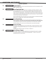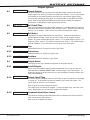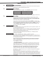
1
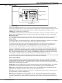
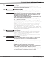
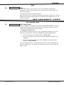
Programming Guide XR5FC/XR5SL Fire Command Processor™ Panels PANEL PROGRAMMER MODEL XR5FC / XR5SL FIRE COMMAND PROGRAMMING GUIDE When using the XR5FC/XR5SL panel for any listing organization's approved methods, refer to this manual and the Specifications Compliance section of the XR5FC/XR5SL Installation Guide (LT-0299). These documents outline the installation and programming requirements of all applications for which the XR5FC/XR5SL is approved. FCC NOTICE This equipment generates and uses radio frequency energy and, if not installed and used properly in strict accordance with the manufacturer's instructions, may cause interference with radio and television reception. It has been type tested and found to comply with the limits for a Class B computing device in accordance with the specification in Subpart J of Part 15 of FCC Rules, which are designed to provide reasonable protection against such interference in a residential installation. If this equipment does cause interference to radio or television reception, which can be determined by turning the equipment off and on, the installer is encouraged to try to correct the interference by one or more of the following measures: Reorient the receiving antenna Relocate the computer with respect to the receiver Move the computer away from the receiver Plug the computer into a different outlet so that computer and receiver are on different branch circuits If necessary, the installer should consult the dealer or an experienced radio/television technician for additional suggestions. The installer may find the following booklet, prepared by the Federal Communications Commission, helpful: "How to identify and Resolve Radio-TV Interference Problems." This booklet is available from the U.S. Government Printing Office, Washington D.C. 20402 Stock No. 004-000-00345-4 Copyright © 1995 - 2009 Digital Monitoring Products, Inc. Information furnished by DMP is believed to be accurate and reliable. This information is subject to change without notice. Digital Monitoring Products b XR5 Programming Guide Table Of Contents Introduction.......................................................................1 1.1 1.2 1.3 1.4 1.5 1.6 1.7 1.8 1.9 Before You Begin..................................................................... 1 About this Guide..................................................................... 1 Reading the Contents.............................................................. 1 Programming Information Sheets............................................. 1 Getting Started....................................................................... 1 Initializing the Panel................................................................ 1 Program from Any Keypad Address.......................................... 1 Accessing the Programmer...................................................... 1 Programming Menu................................................................. 2 Programmer Lockout Codes..................................................... 2 Programming a Lockout Code.................................................. 2 Reset Timeout......................................................................... 2 Special Keys............................................................................ 3 COMMAND Key....................................................................... 3 Back Arrow Key...................................................................... 3 Select Keys............................................................................ 3 Four Function Keys................................................................. 3 Entering Alpha Characters........................................................ 4 Entering Non-Alpha Characters................................................. 4 Keypad Prompts Display Current Programming.......................... 4 Initialization......................................................................5 2.1 2.2 Initialization............................................................................ 5 Clear Programming.................................................................. 5 Communication..................................................................6 3.1 3.2 3.3 3.4 3.5 3.6 3.7 3.8 3.9 3.10 3.11 3.12 3.13 3.14 3.15 3.16 3.17 3.18 3.19 3.20 3.21 Communication....................................................................... 6 Communication Type............................................................... 6 Second Phone Line.................................................................. 6 Account Number..................................................................... 6 DTMF..................................................................................... 6 Receiver 1 Programming.......................................................... 6 Alarm Report.......................................................................... 6 Supervisory/Trouble Reports.................................................... 6 Test Report............................................................................. 6 Backup Reporting.................................................................... 7 First Telephone Number........................................................... 7 Second Telephone Number....................................................... 7 Receiver 2 Programming.......................................................... 7 Pager Type............................................................................. 7 Alarm Reports......................................................................... 7 Supervisory/Trouble Reports.................................................... 7 Test Report............................................................................. 7 Backup Reporting.................................................................... 7 First Telephone Number........................................................... 8 Second Telephone Number....................................................... 8 Pager Identification Number..................................................... 8 Remote Options.................................................................9 4.1 4.2 4.3 4.4 4.5 4.6 Remote Options...................................................................... 9 Remote Key............................................................................ 9 Manufacturer Authorization...................................................... 9 Armed Rings........................................................................... 9 Alarm Receiver Authorization.................................................... 9 Service Receiver Authorization.................................................. 9 System Options................................................................10 5.1 5.2 5.3 5.4 5.5 XR5 Programming Guide System Options......................................................................10 Cross Zone Fault Time............................................................10 Zone Retard Delay..................................................................10 Power Fail Delay.....................................................................10 Reset Swinger Bypass.............................................................10 Digital Monitoring Products i Table of Contents Output Options................................................................11 6.1 6.2 6.3 6.3.1 6.3.2 6.3.3 6.4 6.4.1 6.4.2 6.4.3 6.4.4 6.4.5 Output Options......................................................................11 Bell Cutoff Time.....................................................................11 Bell Action.............................................................................11 Fire.......................................................................................11 Supervisory............................................................................11 Auxiliary................................................................................11 Output Action.........................................................................11 Cutoff Outputs.......................................................................11 Output Cutoff Time................................................................11 Communication Failure Output................................................11 Fire Alarm Output...................................................................12 Fire Trouble Output................................................................12 Zone Information.............................................................13 7.1 7.2 7.3 7.4 7.5 7.6 7.7 7.8 7.8.1 7.8.2 7.8.3 7.9 7.10 7.11 7.12 Zone Information...................................................................13 Zone Number.........................................................................13 Zone Name............................................................................13 Zone Type..............................................................................13 Next Zone?............................................................................14 Alarm Action..........................................................................14 Zone Type Specifications.........................................................14 Armed open...........................................................................15 Message to Transmit...............................................................15 Output Number......................................................................15 Output Action.........................................................................15 Swinger Bypass......................................................................16 Zone Retard...........................................................................16 Cross Zone.............................................................................16 Zone Number.........................................................................16 Stop..................................................................................17 8.1 Stop......................................................................................17 Set Lockout Code.............................................................17 9.1 Set Lockout Code...................................................................17 Appendix..........................................................................18 10.1 10.2 10.3 10.4 10.5 Keypad Status List..................................................................18 Manual Telephone Line Seizure................................................18 How it Works.........................................................................18 2-Button Panic Keys................................................................18 Walk Test...............................................................................19 From the 630F Keypad...........................................................19 From the 692F LED Keypad....................................................19 Table of Common Keypad Messages........................................19 Revisions to this Document Listings and Approvals Digital Monitoring Products ii XR5 Programming Guide Introduction Introduction 1.1 Before You Begin About this Guide This guide provides programming information for the DMP XR5FC and XR5SL Fire Command™ Panels. After this introduction, the remaining sections describe each programming menu item function and its available options. The XR5FC and XR5SL panels contain all programming information in an on-board processor and do not require an external programmer. Reading the Contents Before starting to program, we recommend you read through the contents of this guide. This information allows you to quickly learn the programming options and operational capabilities of the XR5FC and XR5SL panels. In addition to this guide, you should also read and be familiar with the following XR5FC and XR5SL documents: • XR5FC and XR5SL User's Guide (LT-0296) • XR5FC and XR5SL Installation Guide (LT-0299) • XR5FC and XR5SL Programming Sheet (LT-0297) Programming Information Sheets Included with each XR5FC and XR5SL panel is a Programming Sheet. This sheet lists the various keypad prompts and available options for panel programming. Before starting, we recommend you completely fill out the programming sheet with the options you intend to enter into the panel. Having completed programming sheets available while entering data helps to prevent errors and can shorten the length of time you spend programming. Completed sheets also provide you with an accurate account of the panel program you can keep on file for future system service or expansion. The remainder of this Introduction tells you how to start and end an XR5FC/XR5SL programming session. 1.2 Getting Started Ground Yourself Before Handling the Panel! Touch any grounded metal, such as the enclosure, before touching the panel to discharge static. Remove All Power From the Panel! Remove all AC and Battery power from the panel before installing or connecting any modules, cards, or wires to the panel. The XR5FC and XR5SL Fire Command™ panels must be completely installed before beginning programming. Make sure the panels are properly grounded and the AC and battery wires are connected to the correct panel terminals. Initializing the Panel When programming an XR5FC or XR5SL panel for the first time, use the Initialization function described in the Initialization section. Initializing clears the panel memory of any old or incorrect data and resets programming to factory defaults. Program from Any Keypad Address Program the XR5FC and XR5SL panels from an alphanumeric keypad connected to the keypad data bus. See the XR5FC and XR5SL Installation Guide (LT-0299) for keypad addressing and installation information. Accessing the Programmer To access the programmer function of the XR5FC and XR5SL: 1. 2. 3. 4. 5. Place a flat screwdriver across the two J9 RESET jumper wires for two seconds. Remove the screwdriver. Enter the code 6653 (PROG) into the keypad. Enter your Lockout Code (if required). The keypad displays ONE MOMENT as the XR5 dials the Central Station receiver to indicate local programming and out of service status. 6. The keypad displays: PROGRAMMER. You are now ready to start programming the XR5FC and XR5SL panels. Press the COMMAND key to scroll through the programming menu. XR5 Programming Guide Digital Monitoring Products 1 Introduction 1.3 Programming Menu There are 8 programming menu items from which to choose: Menu Item Section in this guide Initialization 2 Communication 3 Remote Options 4 System Options 5 Output Options 6 Zone Information 7 Stop 8 Set Lockout Code 9 To select a section for programming, press any top row Select keys when the keypad displays the name of that section. Detailed instructions for each programming step are found in sections 2 through 9 of this guide. 1.4 Programmer Lockout Codes Although the XR5FC and XR5SL panels allow you to enter the built-in Programmer without a lockout code, you may wish to program one to restrict programming access to only those persons your company authorizes. You can do this by using the SET LOCKOUT CODE feature at the end of the programming menu. Programming a Lockout Code 1. After entering the Programmer menu, the keypad displays PROGRAMMER. Press the COMMAND key to advance through the programming sections until SET LOCKOUT CODE displays (after Stop). 2. Press any top row Select key. At the ENTER CODE: - display, enter a 3 to 5-digit programmer lockout code. Press COMMAND. 3. The display shows ENTER AGAIN. Enter the same lockout code again and press COMMAND. The display shows CODE CHANGED. The new code number must now be entered before accessing the Programmer menu. Write the lockout code number down and keep it in a secure place with access limited to authorized persons only. Lost Lockout Code requires factory reset: If you lose or forget the lockout code, the panel must be sent back to the factory to be reset. There is no field option for gaining access to the panel without a valid lockout code. 1.5 Reset Timeout The XR5FC and XR5SL has a featurethat requires you to enter the Programmer within 30 minutes of resetting the panel. After 30 minutes, if you attempt to program by entering the 6653 (PROG) code, the keypad displays: RESET PANEL. You must reset the panel, enter the program code, then begin programming within the next 30 minutes. If you are already in the Programmer and do not press any keys on the programming keypad for 30 minutes, the panel terminates programming. All data entered up to that point is saved in the panel memory. Use the Stop routine to exit the panel Programmer. Digital Monitoring Products 2 XR5 Programming Guide Introduction 1.6 Special Keys Fire Command Center Function Keys LCD Display POWER TROUBLE ALARM SILENCE RESET ABC TEST MNO DEF 1 GHI 2 JKL 3 4 ENABLE DRILL PQR STU 5 6 9 0 YX Select Keys VWX 7 8 COMMAND COMMAND Key Back Arrow Key COMMAND Key Pressing the COMMAND key allows you to go forward through the programming menu and through each step of a programming section. As you go through the programming, the keypad display shows any current programming already stored in the panel memory. If no change is required for a prompt, press the COMMAND key to advance to the next step. The COMMAND key is also used to enter information into the panel memory such as phone numbers or zone names. Press the COMMAND key after entering the information and it displays correctly on the keypad. Back Arrow Key Use the Back Arrow key to back up one step while in the programming menu or within a programming sec tion. The Back Arrow key also allows you to correct an error by erasing the last character entered. Select Keys The top row of keys are called the Select keys. When the Programmer displays an option for you to select, such as YES or NO, you press the Select key under the option you want to enable. The Select keys also allow you to change programming information currently in the panel memory. As you step through each program option, the keypad displays the current information. To change this information, press the appropriate key under the display then enter the new information If you are changing a phone number or account number, press the Select key followed by the appropriate digit keys. If entering a communication type or choosing a programming option, the keypad displays the available response options above the Select keys. When there are more than four response options avail able, the keypad displays the first four. Pressing the COMMAND key brings up the next one to four options on the display. Pressing the Back Arrow key allows you to review the previous four choices. The Select keys are also used for selecting a section from the programming menu. This is done by pressing any one of the Select keys when the programming section name you want displays. Four Function Keys The four function keys allow the user to quickly and easily perform functions on the 630F. The factory installed keyswitch on the Remote Fire Command Center left-hand side must be turned to the ENABLE position before the keys activate. The keyswitch does not affect the other keys on the keyboard: They are operational at all times with a user code. SILENCE Key—Press the SILENCE key to silence the main alarm bell and the Fire Bell Output. The SILENCE key does NOT stop the alarm report being sent to the central station or reset any alarmed devices. RESET Key—Press the RESET key to perform a sensor reset. Use the RESET key to reset devices such as smoke detectors that have latched in alarm and clear the display of alarms. TEST Key—Press the TEST key to perform a system test. This key tests the alarm bells, communication to the central station, and the backup battery. DRILL Key—Press the DRILL key to display SURE? YES NO. Press the select key under YES to begin the fire drill, which sounds the main bell and activates the Fire Bell Output. Press the select key under NO to return to the status list. Press SILENCE or enter a user code to silence the alarm bells and end the fire drill. XR5 Programming Guide Digital Monitoring Products 3 Introduction 1.7 Entering Alpha Characters Some programming options allow you to enter alphanumeric names. To enter an alpha character, press the key that has that letter written below it. The keypad displays the key number. Next, press the Select key that corresponds to the location of the letter under the key. Pressing a different Select key changes the letter. When another digit key is pressed, the last letter displayed is retained and the process starts over. A B C Right Character Center Character Left Character Figure 2: Keypad Display and Select Keys Figure 1: Keypad Function Keys 1.8 Entering Non-Alpha Characters To enter a space, press the 9 digit key followed by the third Select key. The three characters on the 9 digit key are Y, Z, and space. You can also enter the characters ‑ (dash), . (period), * (asterisk), and # (pound sign) using the 0 (zero) key and the four Select keys from left to right. 1.9 Keypad Prompts Display Current Programming Each programming prompt displayed at the keypad shows the currently selected option in the panel memory. These options are either shown as a number, a blank, or a NO or YES. To change a number or blank to a new number, press any top row Select key. The current option is replaced with a dash. Press the number(s) on the keypad you want to enter as the new number for that prompt. It is not necessary to enter numbers with leading 0s (zero). The XR5FC and XR5SL automatically right justifies the number when you press the COMMAND key. To change a programming prompt that requires a NO or YES response, press the top row Select key under the response not selected. For example, if the current prompt is selected as YES and you want to change it to NO, press the third top row Select key from the left. The display changes to NO. Press the COMMAND key to go to the next prompt. See Figure 3. BELL TST YES Press the third top row Select key. NEXT BELL TST NO The keypad display changes to the newly selected option. Press COMMAND. Figure 3: Changing the Currently Selected Option Digital Monitoring Products 4 XR5 Programming Guide Initialization Initialization 2.1 INITIALIZATION Initialization The Initialization function allows you to set the panel programmed memory back to the factory defaults in preparation for system programming. After you select YES to clear part of the memory, the panel asks if you are sure you want to clear the memory. This is a safeguard against accidently erasing part of your programming. No memory is cleared from the programming until you answer yes to the SURE? YES NO prompt. 2.2 DEFAULTS? NO YES Clear Programming SURE? YES NO YES sets the panel programming back to factory default selections and clears any information stored in Display Events Memory. XR5 Programming Guide Digital Monitoring Products 5 Communication Communication 3.1 COMMUNICATION Communication This section allows the communication settings for the XR5FC and XR5SL panels to be configured. After choosing the Communication Type, continue through the list of additional communication options. 3.2 COMM TYPE: NONE Communication Type This specifies the communication method the panel uses to contact the receiver. Press any Select key to display the following communication options: NONE DD CID NONE - For local systems. Selecting NONE disables the phone line monitor for the Main and Backup phone lines and ends communication programming. DD - Digital Dialer communication to DMP SCS-1R Receivers. CID - Contact ID communication to non-DMP receivers. This format sends Ademco Contact ID communications format report codes. 3.3 2ND LINE NO YES Second Phone Line This option allows the panel to use a second phone line to send reports to the receiver should the first phone line fail. If 2ND LINE is YES, connect a second phone line to the BACKUP phone jack on the panel. Selecting NO disables the phone line monitor for the Backup phone line. 3.4 ACCOUNT NO: 12345 Account Number Enter the account number sent to the receiver. DD - The range of account numbers for Digital Dialer is 1 to 65,535. For account numbers of four digits or less, you do not have to enter leading zeros. CID - The range of account numbers using CID communication is 1 to 9999. 3.5 DTMF 3.6 RECEIVER 1 PROG NO YES DTMF YES enables tone dialing. NO enables rotary dialing. Receiver 1 Programming Allows you to set the options for the first receiver the XR5FC and XR5SL panels attempt to contact when sending reports. The XR5FC and XR5SL support communication to two receivers. 3.7 ALARM NO YES Alarm Report Enter YES to enable Alarm and Alarm Restoral reports to be sent to this receiver. 3.8 SPV/TRBL NO YES Supervisory/Trouble Reports Enter YES to enable Supervisory, Trouble, Trouble Restoral reports, and user zone trouble, fault, and bypass reports to be sent to this receiver. 3.9 TEST RPT NO YES Test Report Enter YES to enable the Recall Test report to be sent to this receiver. When 2nd line is YES, the Recall Test message alternates between the two phone lines. The message is sent on the phone line designated for that day even when the supervision circuit indicates the phone line is bad. This allows both phone lines to be tested as required by NFPA. About the Panel Recall Test Time Once you have finished programming, reset the panel. The Recall Test timer now begins and runs for twelve hours. After twelve hours elapse, the Recall Test is sent to the receiver. Whatever time of day this happens to be is the time the Recall Test is sent every 24 hours. The first Recall Test is made on the main phone line for all ten dial attempts. The next 24 hour period the Recall Test is made on the second phone line for all ten dial attempts. This allows both phone lines to be tested every two days. If the system has any existing Fire, Fire Verify, or Supervisory zones currently in alarm or trouble, or any system monitor ( AC, battery, or phone line) in trouble, the standard S07 Automatic Recall report to the SCS-1R Receiver is replaced by S88 (Automatic Recall OK - Unrestored System) message. Digital Monitoring Products 6 XR5 Programming Guide Communication 3.10 3.11 BACKUP NO YES Backup Reporting YES enables Receiver 1 to be a backup to Receiver 2 in the event the panel cannot contact Receiver 2. First Phone No: - 3.12 Second Phone No: - First Telephone Number This is the first number the panel dials when sending reports to this receiver. A phone number can consist of two lines of 16 characters to equal 32 characters. You can program a three second pause in the dialing sequence by entering the letter P. You can program a dial tone detect by entering the letter D. These characters are counted as part of the 32 allowable characters. Second Telephone Number The panel dials the second number when two successive tries using the first number fail. If the panel cannot reach the receiver after two attempts using the second number, it returns to the first number and makes two additional attempts. A total of ten dialing attempts are made using the first and second phone numbers. If a second phone number is not entered, the first phone number is used for all dialing attempts. Each number can be up to 32 characters in length including any P or D characters entered for pause and dial tone detect. 3.13 RECEIVER 2 PROG 3.14 PAGER? Receiver 2 Programming Receiver 2 defaults are set to NO. If you select YES for any Receiver 2 options, you must have at least one phone number programmed in Receiver 2 programming. NO YES Pager Type This option allows the panel to send Alarm and Trouble reports to a customer's numeric pager. The panel uses DTMF tones for numeric pagers. Selecting NO allows you to use the Receiver 2 Programming to send panel reports to a second receiver. Note: The XR5 communicates in a half-duplex mode with a Glenayre alphanumeric pager terminal. The terminal modem must accept the following parameters: • • • 300 bps Bell 103 protocol Carrier detect response time = 300ms Delay between lost carrier and hang-up = 12.0 seconds 3.15 ALARM 3.16 SPV/TRBL NO YES Supervisory/Trouble Reports See Receiver 1 Supervisory/Trouble Reports section for programming. 3.17 TEST RPT NO YES Test Report Enter YES to enable the Recall Test report to be sent to this receiver. When 2nd line is YES, the Recall Test message alternates between the two phone lines. The message is sent on the phone line designated for that day even when the supervision circuit indicates the phone line is bad. This allows both phone lines to be tested as required by NFPA. 3.18 BACKUP XR5 Programming Guide NO YES Alarm Reports See Receiver 1 Alarm Reports section for programming. NO YES Backup Reporting YES enables Receiver 2 to be a backup to Receiver 1 in the event the panel cannot contact Receiver 1. Digital Monitoring Products 7 Communication 3.19 First Phone No: - 3.20 Second Phone No: - 3.21 PAGER ID NUMBER - Digital Monitoring Products 8 First Telephone Number This is the first number the panel dials when sending reports to this receiver. A phone number can consist of two lines of 16 characters to equal 32 characters. You can program a three second pause in the dialing sequence by entering the letter P. You can program a dial tone detect by entering the letter D. These characters are counted as part of the 32 allowable characters. Second Telephone Number When PAGER? is NONE, the panel dials the second number when two successive tries using the first number have failed. If the panel cannot reach the receiver after two attempts using the second number, it returns to the first number and makes two additional attempts. A total of ten dialing attempts are made using the first and second phone numbers. If a second phone number is not entered, the first phone number is used for all dialing attempts. Each number can be up to 32 characters in length including any P or D characters entered for pause or dial tone detect. Pager Identification Number Enter a pager identification number if your pager uses one. For numeric paging, the panel waits for nine seconds after dialing the First Phone Number before sending the Pager ID. After the Pager ID is transmitted, the panel waits another three seconds before sending the actual pager message containing the panel reports. Program additional three second pauses by entering a letter P for each pause to add. XR5 Programming Guide Remote Options Remote Options 4.1 REMOTE OPTIONS Remote Options This section allows the information needed for Remote Command/Remote Programming operation to be entered. A description of the Remote Options follow. Note: A complete functional checkout of the panel is required following any programming or reprogramming. 4.2 Remote Key RMT KEY: This option allows you to enter a code of up to eight digits for use in verifying an alarm or service receiver authority to perform a remote command/programming session. The receiver must give the correct key to the panel before being allowed access. Default is blank. To enter a new Remote Key, press a top row Select key and enter any combination of up to eight digits. The numbers you enter appear as asterisks. Press COMMAND. 4.3 MFG AUTH NO YES Manufacturer Authorization Enter YES to allow DMP service technicians to access the panel when required during system service or troubleshooting. This automatically expires within one hour. DMP remote service is provided on a read only basis: DMP technicians can look at the system programming and make suggestions only. 4.4 ARMED RINGS: 4.5 ALR RCVR NO YES Alarm Receiver Authorization Enter YES to enable the panel to accept remote commands and programming from the alarm receiver. The Remote Key option can also be required. When YES is selected, the panel requests the alarm receiver key during its first alarm communication with the first receiver. The panel retains this alarm receiver key in memory and allows remote commands to be accepted from the alarm receiver. If an alarm occurs during a remote connect, the alarm report is immediately sent to this receiver only. Enter NO to not accept remote commands and programming from the alarm receiver. 4.6 SVC RCVR XR5 Programming Guide 0 Armed Rings Enter the number of rings the panel counts within a two minute period before answering the phone line. Enter any number from 1 to 15. Default is 0 rings. If 0 (zero) is entered, the panel does not answer the phone. If NONE is selected as the Communication type, the ring detect function is disabled and the 984 Command function must be used to seize the phone line. See Manual Telephone Line Seizure Section in the Appendix. Answering machine bypass procedure: Entering a number greater than 0 (zero) into Armed Rings allows a central station operator to connect remotely with the panel. How it works: The operator calls the panel, rings the phone once and then hangs up. The panel stores this attempt to communicate. The operator then calls back within 30 seconds causing the panel to seize the phone line and allow remote programming. NO YES Service Receiver Authorization YES enables the panel to accept remote commands and programming from a secondary service receiver other than the alarm receiver. A Remote Key can also be required. With YES selected, the panel requests the service receiver key the first time it is contacted by the service receiver. The panel retains this service receiver key in memory and accepts remote commands from the service receiver. If an alarm occurs during a remote connect, the panel disconnects from the service receiver and calls the alarm receiver. Alarm reports are only sent to the alarm receiver. It is important that the alarm receiver key and the service receiver key programmed at the central station are NOT the same so the panel can determine the difference between receivers. When NO is selected, the panel does not accept remote commands and programming from a secondary service receiver. Digital Monitoring Products 9 System Options System Options 5.1 SYSTEM OPTIONS System Options This section allows you to select system wide parameters used in the operation of the XR5FC and XR5SL system. 5.2 CRS ZONE TM: 0 Cross Zone Fault Time Enter the time allowed after a zone trips to indicate a zone fault condition. When a zone programmed for cross zoning trips, the panel begins counting down the Cross Zone Fault Time you enter here. If the same zone or another zone trips within this time, or prior to a Sensor Reset, an alarm report is sent to the receiver for both zones. If the Cross Zone Fault Time expires without the second zone trip, a zone fault report from the first zone is sent to the receiver. The Cross Zone Fault Time can be set from 4 to 250 seconds in one second increments. Enter 0 (zero) to disable the Cross Zone Fault Time feature. 5.3 RETARD DLY: 0 Zone Retard Delay Enter the time allowed for zones to be shorted before the panel acknowledges the short as an alarm. This option is primarily used on waterflow zones where fluctuations in the flowswitch may short the zone in the absence of an actual alarm condition. The Retard Delay can be set from 0 to 250 seconds in one-second increments. 5.4 PWR FAIL HRS: 1 Power Fail Delay This option tracks the duration of an AC power failure. When the AC power is off for the length of the programmed delay time, an AC power failure report is sent to the receiver. The delay time can be set from 0 to 15 hours. Default is 1. 5.5 RST SBYP NO YES Reset Swinger Bypass When YES is selected, a swinger bypassed zone is automatically reset if it remains in a normal condition for one hour after being bypassed. A report of the reset is automatically sent to the receiver. Digital Monitoring Products 10 XR5 Programming Guide Output Options Output Options 6.1 Output Options OUTPUT OPTIONS This function allows you to program the panel Bell Output functions and certain Output options for the Form C relays and annunciator outputs. Form C relay outputs are available on the panel 6-position terminal strip. Annunciator outputs (open collector) are available by using the 4-wire output header on the XR5FC and XR5SL board. Refer to the XR5FC and XR5SL Installation Guide (LT-0299) for complete information. A description of each output option follows: 6.2 BELL CUTOFF: 15 Bell Cutoff Time Enter the maximum time the Bell Output remains on. If the Bell Output is manually silenced or the system is disarmed, the cutoff time resets. The Bell Cutoff Time can be from 1 to 15 minutes. Enter 0 (zero) to provide continuous bell output. 6.3 BELL ACTION . . . . . Bell Action This defines the type of Bell Output for zone alarms. Trouble conditions do not activate the Bell Output. There are four bell actions you can program for Bell Output: To provide a steady Bell Output, enter S. For a pulsed output, enter P. For Temporal Code 3, enter T. For California School Code, enter C. For no Bell Output, enter N. Below is a list of the bell action for three of the zone types: 6.3.1 FIRE TYPE: P Fire Defines Bell Action for Fire and Fire Verify Type Zones 6.3.2 SUPRVSRY TYPE: N Supervisory Defines Bell Action for Supervisory Type Zones 6.3.3 AUXLRY I TYPE: 6.4 N Auxiliary Defines Bell Action for Auxiliary 1 Type Zones OUTPUT ACTION . . . Output Action This option allows you to define the operation of the panel outputs. 6.4.1 CO OUTS: - - - - Cutoff Outputs Any or all of the available outputs can be programmed here to turn off after the time specified in OUTPUT CUTOFF TIME. See the Output Cutoff Time section. To disable this option, press any Select key to clear the display of output numbers and then press COMMAND. 6.4.2 CUTOFF TIME: 0 Output Cutoff Time If a Cutoff Output is assigned, enter a Cutoff Time of up to 15 minutes for the output to remain on. If the output is turned off manually, the Cutoff Time resets. The Cutoff Time can be from 1 to 15 minutes. Enter 0 (zero) to provide continuous output. The Cutoff Timer is shared by all outputs. If a second output trips, the timer is not reset. Both outputs turn off when the original time expires. 6.4.3 COM FAIL OUT: 0 Communication Failure Output This output is turned on when a DD system fails to communicate with the receiver after ten successive dial attempts. Enter 0 (zero) to disable this output. XR5 Programming Guide Digital Monitoring Products 11 Output Options 6.4.4 FIRE ALR OUT: 0 Fire Alarm Output This output is turned on any time a fire type zone is placed in alarm. The output is turned off using the Sensor Reset option when no additional fire type zones are in alarm. Enter 0 (zero) to disable this output. 6.4.5 FIRE TRB OUT: 0 Fire Trouble Output This output is turned on any time a fire type zone is placed in trouble, when a supervisory type zone is placed in alarm or trouble, or when AC power, battery power, or either phone line is in trouble. The output is turned off when all trouble conditions are restored to normal. Enter 0 (zero) to disable this output. Digital Monitoring Products 12 XR5 Programming Guide Zone Information Zone Information 7.1 ZONE INFORMATION Zone Information This allows you to define the operation of each protection zone used in the system. A description of each programming option follows: 7.2 ZONE NO: Zone Number – Enter the zone number to program. Press COMMAND to enter a zone name. Address Panel 3 Programming Zone Number 1-5 31-34 Note: At least one 630F keypad is required to support alarm display of zones 31-34. 7.3 NAME: * UNUSED * Zone Name Press any Select key and enter up to ten characters for the zone name. Each operating zone in the system must be given a name. This name can display at the keypads when the zone is bad or viewed in Display Events. The zone name is also sent to the receiver as part of a zone event report. A zone that is not part of the system must be marked *UNUSED*. To mark a zone unused, press a top row Select key to delete the old name, then press the COMMAND key. The programmer automatically programs the name as * UNUSED *. If you selected DEFAULTS? NO YES to clear the panel memory during Initialization, the zones are already marked * UNUSED *. 7.4 ZONE TYPE: FIRE Zone Type The Zone Type defines the panel response when the zone is opened or shorted. See the Zone Type Specification chart. When you assign a Zone Type to a zone, automatic responses are made for the zone. There are four Zone Types to choose from. Each response functional details are described in the Zone Type Specification chart.. To enter a new Zone Type, press any top row Select key. The display lists the following four Zone Types. FI SV A1 FV FI = Fire, SV = Supervisory, A1 = Auxiliary 1, and FV = Fire Verify. Note: Supervisory Type zones provide default zone names: If SV (Supervisory) is selected as the zone type, SUPRVSRY n (n = zone number) is automatically stored as the 10-character zone name. When the Zone Type you want to select displays, press the Select key beneath its name. The See the Zone Type Specification chart gives an outline of the Alarm Action for each Zone Type. Press COMMAND to continue. Zone Type Descriptions FI (Fire zone) - Used for any type of powered or mechanical fire detection device. Typical applications are for smoke detectors, sprinkler flowswitches, manual pull stations, and beam detectors. Cross zoning is compatible with the Fire zone type. SV (Supervisory zone) - Used to provide 24-hour zone supervision to devices associated with fire systems. Typical applications are tamper switches on Post Indicator Valves (PIVs), gate valves, and low and high temperature gauges. A1 (Auxiliary 1) - These zones allow you to customize the operation for peripheral fire protection devices. FV (Fire Verify zone) - Used primarily for smoke detector circuits to verify the existence of an actual fire condition. When a Fire Verify zone initiates an alarm, the panel performs a Fire Reset. If any Fire zone initiates an alarm within 120 seconds after the reset, an alarm is indicated. If an alarm is initiated after 120 seconds, the cycle repeats. XR5 Programming Guide Digital Monitoring Products 13 Zone Information 7.5 NEXT ZN? NO YES Next Zone? When YES is selected, the programming for the zone terminates and the display returns to ZONE NO: - allowing you to enter a new zone number. To make changes to the Alarm Action for a zone, answer the NEXT ZONE? prompt with NO. The Alarm Action is then defined in the following sections. 7.6 alarm action . . . . Alarm Action The Alarm Action section allows you to change or confirm the default alarm characteristics of a zone type. The Fire Verify zone type functions the same as Fire zone with the following exceptions: When a Fire Verify zone is placed into shorted condition, the panel performs a Sensor Reset and does not send a report. If any Fire Verify or Fire zone initiates an alarm within 120 seconds after the reset, an alarm is indicated. If an alarm is initiated after 120 seconds, the cycle repeats. If no other Fire Verify or Fire zone is alarmed within 120 seconds, a zone fault report is sent to the receiver. 7.7 Zone Type Specifications The XR5FC and XR5SL panels contain four default zone types for use in configuring the system. These zone types provide the most commonly selected functions for their applications. FI SV A1 FV 0 to 4 S P M F – – – – A T L – A A A A 0 0 0 0 Action FV A T L – T T T T Output A1 Message SV Short Action Fire Supervisory Auxiliary 1 Fire Verify FI Open Output Use this section of the programming sheet to record the program options you selected for the XR5 panel zone. Type Message Zone Information 0 to 4 S P M F – – – – 0 0 0 0 Swinger Bypass Retard Delay Cross Zone N or Y N or Y N or Y N N N N N N N N N N N No. Zone Name 1 2 3 4 5 31 32 33 34 Programmable Zone Options Descriptions Below is a description of the various zone options shown on the table above. Zone Information - The complete spellings of the abbreviations used for the zone types. Type - The abbreviations that display on the keypad for the zone types. Message - A = alarm report, T = trouble report, L = local with no report, – (dash) = no report. Output - This only refers to the four XR5FC/XR5SL relay outputs. Action - This selects the type of relay output: S = steady, P = pulse, M = momentary, and F = follow Swinger Bypass - Allows the zone to be automatically bypassed after three trips. Retard Delay - Provides a time delay before an alarm initiates from a short on this zone. Cross Zone - Provides cross zoning for this zone. Digital Monitoring Products 14 XR5 Programming Guide Zone Information 7.8 ARMED OPEN Armed open Defines the action taken by the panel when the zone is placed into an open condition. There are three actions to define: the Message to transmit, which Relay output to activate, and the Relay output action. 7.8.1 MSG: TROUBLE Message to Transmit You can send two report types to the receiver: Alarm and Trouble. These are represented by the characters A and T. Press any top row Select key to display the zone full reporting options. A T L - Alarm - Selecting A, allows an alarm report to be sent to the receiver and the bell output to activate according to zone type. See the Bell Action section. The zone name appears in the panel alarmed zones status list. Trouble - Selecting T allows a trouble report to be sent to the receiver and the zone name to appear in the panel alarmed zones status list. You cannot change the Alarm (A) and Trouble (T) action for Fire (FI), Fire Verify (FV), or Supervisory (SV) zone types. Local - When you select L, an alarm report is NOT sent to the receiver. The bell output still activates according to zone type and the zone name appears in the panel alarmed zones status list. NOTE: You can also select L for a zone to send alarm reports to the subscriber's personal pager only, and not to the central station. You must enable the Pager option in the Communication section to operate this feature. – (dash) - When you select – , reports are NOT sent to the receiver. The bell output does not activate and there is no display in the panel alarmed zones status list. Only the Output Number currently selected activates. 7.8.2 OUTPUT NO: 0 Output Number You can specify any of the outputs on the XR5FC or XR5SL to activate by a zone condition. The output can be activated regardless of the report to transmit or whether or not the zone is programmed as local. To enter an Output Number, press any top row Select key followed by the output number 1 to 4. Press the COMMAND key. 7.8.3 ACTION: Output Action Entering an Output Number displays this prompt allowing you to assign an output action to the relay. A description of the available output actions follows: STD PLS MOM FOLW Steady - The output is turned on and remains on until a Sensor Reset is performed or the output cutoff time expires. Pulse - The output alternates one second on and one second off until a Sensor Reset is performed or the output cutoff time expires. Momentary - The output is turned on only once for one second. Follow - The output is turned on and remains on while the zone is in an off normal, or bad condition. When the zone restores, the output is turned off. After selecting the Message, Output Number and Action, the display prompts you for the same three selections for Armed Short conditions. When you have programmed all of the zone conditions, the Swinger Bypass selection then displays. XR5 Programming Guide Digital Monitoring Products 15 Zone Information 7.9 SWGR BYP: NO YES Swinger Bypass YES allows the zone to be bypassed by the panel after three alarm, trouble, or local trips within one hour. Selecting NO disables swinger bypassing for this zone. After the first trip, if the zone does not trip two more times within an hour, the bypass trip counter returns to zero. To automatically bypass it, the zone must trip a full three times within a subsequent hour. A report of the swinger bypass is automatically sent to the receiver. Keypads on the system display the zone name followed by – BYPAS until a Sensor Reset is performed or the zone automatically resets when Reset Swinger Bypass is enabled. 7.10 RETARD: NO YES Zone Retard When you select YES, the zone operates with the specified Retard Delay. This retard functions only in zone short conditions. The zone must remain shorted for the full length of the Retard Delay before the panel recognizes its condition. If you select NO, the zone operates without a Retard Delay. 7.11 CRS ZONE NO YES Cross Zone Select YES to enable cross zoning for this zone. Cross zoning requires this zone to trip twice, or this zone and another cross zoned zone to trip prior to a Sensor Reset, before an alarm report is sent to the receiver. How it works When a zone programmed for cross zoning trips, the Bell and Output action assigned to the zone activates and the Cross Zone Fault Time specified in System Options begins to count down. If the same zone or another zone programmed for cross zoning trips within this time, or prior to a Sensor Reset, an alarm report is sent to the receiver for both zones. If no other zone programmed for cross zoning trips before the cross zone fault time expires, the panel sends a fault report for the zone to the receiver. This fault report does not inhibit a second zone from tripping and generating an alarm prior to the next Sensor Reset. If the zone programmed for cross zoning trips and then restores and trips again, the panel sends an alarm report for that zone only. Cross zoning is not selectable on Fire Verify zone types. 7.12 ZONE NO: – Zone Number Enter the zone number you want to program next. Return to the Zone Information section and follow each programming prompt description. If all zones are programmed, press the Back Arrow key at the ZONE NO: – display to continue. Digital Monitoring Products 16 XR5 Programming Guide Stop Stop 8.1 STOP Stop At the STOP prompt, press any Select key to exit the XR5FC or XR5SL panel programmer function. When selected, the panel performs an internal reset and exits the programmer. The Stop function clears the panel Status List. During the Stop function, all keypad displays are momentarily blank for two seconds. Afterwards, the programming function is terminated and the keypads return to the Status List display. Set lockout code Set Lockout Code 9.1 SET LOCKOUT CODE Set Lockout Code Pressing COMMAND at the STOP prompt displays SET LOCKOUT CODE. This feature allows you to program a special code that is then required to gain access to the panel internal Programmer through the keypad. Changing the Lockout Code You can change this code at any time to any combination of numbers from 3 to 5 digits long (100 to 65535). Do not use leading zeros for the lockout code. 1. Press any Select key. The display changes to ENTER CODE: -. 2. Enter a 3 to 5-digit code (do not enter a number higher than 65535). Press COMMAND. 3. Enter the new Lockout Code again. Press COMMAND. The keypad display changes to CODE CHANGED. Once you change the code, it is important that you write it down somewhere and store it in a safe place. Lost lockout codes require the panel to be sent back into DMP for repair. XR5 Programming Guide Digital Monitoring Products 17 Appendix Appendix 10.1 Keypad Status List The Status List is the current status of the system or records of recent system events that display on the alphanumeric keypads. If an event occurs on the system, such as an AC failure, the keypad displays the AC POWER -TRBL message. This is a system event that is placed into the Status List to alert the user to a problem. Some Status List items remain in the display until manually cleared and some are cleared automatically when the condition returns to normal. Below is a complete list of status and event displays the keypad can show in the Status List: Description Must be cleared manually? Fire and Supervisory zone alarms Yes - by Sensor Reset Fire and Supervisory zone troubles No - clears when zone restores All other zone alarms No - clears when zone restores System monitor troubles (AC and battery trouble) No - clears when condition restores Zone bypasses No - clears at Sensor Reset or Reset Swinger Bypass Remote keypad messages No (Sent to the keypad by your office or central station) Each item in the list displays for four seconds. When there are multiple items in the list, you can use the COMMAND or Back Arrow keys to scroll forward or back through the items. If there are no items in the Status List, the keypad displays SYSTEM NORMAL. 10.2 Manual Telephone Line Seizure This feature allows you to connect with a remote receiver either by having the panel pick up the phone line while the receiver is ringing the line or by entering a phone number for the panel to dial. This feature is primarily used when bringing a new account on-line as it allows your office or the central station to connect to the panel and upload a custom program. How it Works While the panel is in the Status List, press the numbers 984 and then the COMMAND key. The keypad display changes to NBR PICKUP. NBR Press the Select key under NBR to enter a phone number for the panel to dial. Press each number key slowly and deliberately. The panel dials each number as it is pressed. If you make a mistake, press the Back Arrow key. The panel stops dialing and returns to the NBR PICKUP display. You can enter up to 15 characters for the phone number. To enter a # (pound sign) or * (asterisk) press the 0 (zero) key and third Select key (pound) or fourth Select key (asterisk). The panel makes ten attempts to reach the receiver. If, while attempting to contact the receiver, the panel needs to send an alarm report, the dialing attempts stop and the panel uses the line to send its report. PICKUP The panel immediately seizes the phone line and sends a carrier tone to the receiver. 10.3 2-Button Panic Keys The XR5FC and XR5SL panels support the 2-button Fire (flame icon) feature on the 630F and 692F keypad. Pressing the two right Select keys sends a zone 39 Fire alarm to the central station receiver. Digital Monitoring Products 18 XR5 Programming Guide Appendix 10.4 Walk Test The XR5FC and XR5SL panels provide a walk test feature that allows a single technician to test the protection devices connected to zones on the system. To conduct the Walk Test: From the 630F Keypad 1. From the keypad, enter the code 8144. If the system is monitored and the communication type is set to DD, the system sends a System Test Begin report to the central station. The keypad then displays WALK TEST for four seconds followed by TRIPS: X X X END. The " X X X " represents the number of trips that occur during the Walk Test. 2. Once in the Walk Test, you can go around and trip each protection device. As each device is tripped, the panel sounds the alarm bells for two seconds and then performs an automatic Sensor Reset. Continue tripping devices until the entire system has been tested. The trip counter on the keypad display increments by one each time a device is opened or shorted 3. To end the test, press the Select key under END. The panel sends a System Test End to the central station and performs a final Sensor Reset. At the end of the test, the keypad displays any zones that failed to trip. Below are two examples: Keypad display: SOUTH SMOK –FAIL Keypad display: LOBBY HEAT –FAIL From the 692F LED Keypad 1. From the keypad, enter the code 8144. If monitored, the system sends a System Test Begin report to the central station. The bottom row of zone LEDs (yellow) begin to pulse. 2. Once in the Walk Test, walk around and trip each protection device. As a device is tripped, the zone alarm LED on the keypad turns on, the panel sounds the alarm bells for two seconds and the panel performs an automatic Sensor Reset. The alarm LED stays on for the duration of the Walk Test. Continue tripping devices until the entire system has been tested. 3. To end the test, press the RESET key and enter the user code or press COMMAND + 4 + 7. The panel sends a System Test End to the central station. 10.5 Table of Common Keypad Messages Message Meaning Possible Solutions Invalid Code The user code you entered is not recognized by the system. Check the user code and try again. AC Trouble The system is not getting proper power. Ensure the AC connections are good. Battery is either low or missing. Ensure the battery connections are good and the battery is still good. Battery Trouble System Trouble There is a problem with one or more of the or Service components in the system. Required System Busy Transmit Trouble Ensure there is not a short or open condition on the green data wire to the keypad. You may also need to check that all of the keypads and expansion modules on the bus are good. The system is performing another task with a higher priority. Wait a few moments for the system to complete the task. If the message displays for a long period of time, the processor could be locked up. The panel attempted to communicate with the central station three times and has not succeeded. Verify your communication type, account number, and phone number. Ensure the telephone line is connected and working properly. ENTER CODE (entering Programming) A lockout code is programmed into the panel. Enter the lockout code. ONE MOMENT The panel is dialing the Central Station to indicate local programming session and outof-service status XR5 Programming Guide Once the message is sent, programming resumes. Digital Monitoring Products 19 Revisions Revisions to this Document This section explains the changes made to this document during this revision. This section lists the date the change was made, the section number and section heading, and a brief explanation of the change. Date Section Number and Heading 1.01 1.6 Special Keys 4.4 Armed Rings 5.4 Power Fail Delay 7.2 Zone Number 7.7 Zone Type Specifications 10.3 2-Button Panic Keys 10.4 Walk Test 10.7 Serviceman Programmer Access 10.8. Table of Common Keypad Messages Back Cover Digital Monitoring Products 20 Quick Explanation of Changes Replaced 690F with 630F Keypad; Added Four Function Keys section Corrected default value Corrected default value Added chart Added Zones 31-34 for 714/715 Expansion Removed 690F, added 630F Removed 690F, added 630F Section removed. Never implemented. Removed incorrect messages and renumbered 10.5. Added Listings and Approvals XR5 Programming Guide This page intentionally left blank XR5 Programming Guide Digital Monitoring Products 21 FCC Part 15 FCC Part 68 Registration ID CCKUSA-18660-AL-R California State Fire Marshal (CSFM) New York City (MEA) Underwriters Laboratories (UL) Listed ANSI/UL 864 Fire Protective Signaling 800-641-4282 INTRUSION • FIRE • ACCESS • NETWORKS www.dmp.com 2500 North Partnership Boulevard Made in the USA Springfield, Missouri 65803-8877 9073 LT-0312 1.01 © 2009 Digital Monitoring Products, Inc. Listings and Approvals