1
GRP Redundant Processor Support
Feature Summary
The GRP redundant processor feature allows you to install two gigabit route processors (GRPs) in a
Cisco 12000 series router. One GRP functions as the primary processor. The primary GRP supports
all normal GRP operation. The other GRP functions as the secondary processor. The secondary GRP
monitors the primary and will take over normal GRP operations if it detects a failure in the primary
GRP.
The GRP redundant processor feature is not a hot standby system wherein the secondary GRP
duplicates the state of the primary. The benefit of having the secondary GRP monitor the primary,
rather than duplicate the primary, is that a software failure is unlikely to affect both processors. The
tradeoff is that network services will be disrupted while the secondary GRP takes over and the router
recovers. The recovery happens faster, however, than if the router performed a cold restart.
The primary and secondary GRP can be placed in any available card slot in the router chassis. You
may want to consider physical access and cable locations when choosing where to place the GRPs.
Each GRP must have the resources to run the router on its own, which means all GRP resources are
duplicated. In other words, each GRP has its own Flash device, Ethernet, serial, and console port
connections. The console port connections do not use a “Y” cable. Instead, you connect a separate
terminal console cable and monitor to each GRP.
You can access the secondary GRP resources while it is in standby mode. For example, you can use
the copy EXEC command to transfer an image to the secondary GRP flash device. (Refer to “Device
Access,” later in this publication.) By default, the startup-config on the secondary GRP is always
synchronized to the startup-config on the primary.
There are two common ways to use GRP redundant processor support. You can run identical Cisco
IOS software on both GRPs, which protects against GRP hardware failure. Alternatively, you can
run different Cisco IOS images on each GRP. This method is useful, say, when you want to run a
newer Cisco IOS image on one GRP and revert to an older Cisco IOS image if you encounter
problems.
Benefits
The GRP is no longer a single point of hardware failure. Any permanent hardware failure in the
primary GRP is recovered by the secondary GRP, which increases the level of network service and
reliability demanded by customers.
The GRP redundant processor feature is implemented with no impact on the GSR per-line switching
performance, where packet routing is performed by Cisco express forwarding (CEF) in the line
cards.
GRP Redundant Processor Support 1
Platforms
Restrictions
This section describes situations you must avoid and other considerations relevant to using GRP
redundant processor features.
•
•
Booting from the network is not currently supported by the GRP redundant processor feature.
•
The GRP redundant processor feature is disabled if any Cisco IOS 11.2 GS software prior to
release 11.2(15)GS2 is running on any GRP installed in the router chassis.
•
The secondary GRP uses a slot in the router chassis that might otherwise be available for a line
card. Therefore, in a dual-GRP system, the maximum per-chassis throughput may be less in
comparison to a single-GRP system with a line card in that slot.
A maximum of two GRP cards may be installed in a Cisco 12000 series router chassis. The GRP
redundant processor feature supports a primary and a secondary GRP.
Cisco IOS software prior to 11.2(15)GS2 does not support redundant processors and will interfere
with redundant system operation. We recommend that you install release 11.2(15)GS2 software on
the bootflash: devices on the GRP and that you remove earlier versions of the Cisco IOS software.
Platforms
This feature is supported on these platforms:
•
Cisco 12000 series router
Prerequisites
You must have a second GRP to install in your Cisco 12000 series router. Carefully review the
information in “Installing Second GRP and Configuring Hardware Backup Task List” before
installing the second GRP.
Prior to installing a second GRP, you must upgrade the Cisco IOS software on the existing GRP to
a version that supports the GSR redudundancy feature.
The second GRP requires a separate terminal connected to its serial console port, and it requires a
separate Ethernet connection.
Supported MIBs and RFCs
This feature supports the following MIBs:
•
OldCiscoChassisMIB
For descriptions of supported MIBs and how to use MIBs, see Cisco’s MIB website on CCO at
http://www.cisco.com/public/sw-center/netmgmt/cmtk/mibs.shtml.
No RFCs are supported by this feature.
2
Cisco IOS 11.2(15)GS2
Booting and System Images
Functional Description
This section provides additional information on GRP redundant processor implementation.
•
•
•
•
•
•
•
•
•
•
•
Booting and System Images
Redundancy Arbitration
Secondary Console
Device Access
Local Ethernet
Failover
Field Diagnostics
System Logs
Crash Dumps
Additional Diagnostic Aids
Additional GRPs
Booting and System Images
On hardware reset, each GRP in a dual GRP system will boot the Cisco IOS image specified in the
startup-config. The image specification is identified in a ROM monitor variable, and it is this
variable, in combination with the config-register settings, that determines the boot image. In basic
redundant GRP operations, the two GRPs run identical Cisco IOS images and identical
configurations. User and configuration commands assist this duplication of software and data.
It is also possible to run dual GRPs with different IOS images and configurations in the two GRPs.
This is useful if you want to experiment with a different IOS version or try new configuration
features while providing for automated fallback to a previous version.
When a GRP that supports redundancy detects another GRP running an earlier version of Cisco IOS
software that does not support redundancy, the former GRP will reload itself and enter a wait state.
This action allows the latter GRP to operate without interference so that it can be reconfigured and
loaded with Cisco IOS software that supports redundant processors.
Redundancy Arbitration
After the GRPs have booted the Cisco IOS software, but before they parse the startup-config, the two
GRPs arbitrate to decide which one should be the primary and which one should be the secondary. If
all else is equal, the GRP in the lowest- numbered slot will become the primary. If the GRPs differ
in some way, such as running different versions of software or firmware, the arbitration mechanism
makes the best choice as determined by the arbitration algorithms. These may account for the
versions of IOS running on the GRPs, how recent the startup-configs are, and whether the
startup-config was saved in this chassis.
Once the arbitration mechanism selects a primary GRP, it will load its startup-config. If the
startup-config does not explicitly disallow it, the primary GRP ensures that the startup-config on the
secondary GRP is identical to that on the primary GRP. This synchronization typically involves
copying the startup-config to the secondary GRP. The primary also loads the linecards and completes
the remainder of the initialization.
GRP Redundant Processor Support 3
Functional Description
Choosing the correct primary GRP is important. If only one of the two GRPs has a valid startup-config, that
GRP becomes the primary. If a GRP with an invalid startup-config became primary, that invalid configuration
could be copied to the other GRP, destroying the correct version. Avoiding an invalid startup-config is why the
arbitration mechanism evaluates whether a GRP has a startup-config that was saved while in this router chassis,
and whether the startup-config is the most recent one saved in the chassis.
You can override most of the arbitration mechanism and specify that the GRP in a particular slot is
the primary whenever the system boots. See the command description for the redundancy prefer
EXEC command for usage guidelines.
Secondary Console
The console port on the secondary GRP appears directly connected to a vty port on the primary GRP.
This allows either console to be used to monitor and control the router. However, if there is a permanent failure
on one GRP, you can use the console connected directly to the other GRP. This is why you have separate
connections to the console ports of both GRPs.
Device Access
When the GSR is running in redundant mode, the primary GRP can access the secondary GRP
NVRAM and Flash.
Most users will want to keep the startup-config file on the secondary GRP identical to the
startup-config file on the primary GRP. Automatic synchronization is enabled by default and can be
configured by using the auto-sync main-CPU redundancy configuration command. In auto-sync
mode, changes to the primary startup-config file are automatically applied to the secondary.
No equivalent synchronization mechanism exists for the Flash devices. The Flash devices must be
synchronized manually if you want to keep the Flash on the secondary GRP identical to the Flash in
on the primary GRP.
When using file management commands such as copy and delete, you can specify the command
affects the secondary GRP by adding “sec-” to the device name. For example,
copy slot0: sec-slot0:
Device names that accept sec- are as follows:
sec-slot0:
sec-slot1:
sec-bootflash:
sec-nvram:
Whenever you update the startup-config file on the secondary GRP, that action updates the ROM
monitor variables and the configuration register on the secondary GRP.
These settings may not be exact copies of the primary's ROM monitor variables and configuration register.
Instead, the variables and settings are set to appropriate values, as determined by the primary GRP, which may
differ from those on the primary due to specific hw-module global configuration commands. The end result is
that any ROM and configuration register settings on the secondary GRP are overwritten by the values
chosen by the primary GRP.
4
Cisco IOS 11.2(15)GS2
Local Ethernet
Note When the startup configuration is updated with copy [tftp | rcp | ... ] startup-config, and
auto-sync is enabled, the boot variables on the secondary GRP will be updated according to the values specified
in the current running-config. These values may or may not correspond to what is set in the new startup-config,
just as the values of these variable on the primary may or may not correspond to the startup-config. To avoid
this problem, use copy running-config starup-config to update the startup configuration.
Local Ethernet
The GSR router provides one Ethernet port for each GRP. However, software restrictions limit the
router to using only the Ethernet port on the primary GRP. The MAC address for the Ethernet port
is held in the chassis NVRAM, while the IP address is be taken from the startup-config. The same
MAC address and, typically, the same IP address will be used regardless of which GRP is primary.
The router loses no functionality by not using the Ethernet port on the secondary. For security
reasons, access to the secondary is mediated by the primary. Restricting Ethernet access to the
primary Ethernet port fits into this access model.
There are some consequences due to these restrictions, including the following:
•
•
Network booting from local Ethernet is not currently allowed. Booting is restricted to Flash.
If a primary GRP fails, it does not attempt to use its Ethernet to send a core dump. Instead, it informs the
secondary GRP that a dump is available. When the secondary is ready to process the dump, it will request
the crash data from the failed primary, then send it to the network destination defined in the exception
dump global configuration command.
Failover
The term failover describes the event when one GRP card takes over operation from another. A
failover can be forced, by entering the redundancy force-failover EXEC command, or a failover
occurs when the primary GRP fails and the secondary GRP takes over.
The secondary GRP monitors so-called heartbeat messages from the primary GRP. If no heartbeat
messages are detected for a few seconds, the secondary takes over router operations from the failed
primary. The primary also monitors heartbeat messages from the secondary and attempts to reload
the secondary if the heartbeats cease.
When failover occurs, it interrupts system operation momentarily. The following events occur during
failover:
•
•
•
•
•
•
The failed primary GRP will be reset and reloaded, assuming the GRP is properly configured.
Linecards are reloaded to bring them to a known state.
The router stops passing traffic.
Route information is lost.
All connections are lost.
The secondary GRP card takes over as the primary GRP. Because this formerly-secondary GRP
card has separate image and configuration files, it can act as the sole processor. It will establish
connections with any peer routers to discover route information. The routing tables are thereby
regenerated and downloaded to the linecards.
When a primary GRP detects a fatal hardware or software error, it sends a message to the secondary
GRP. In this instance, the secondary takes over immediately, without waiting the few seconds for the
heartbeat detection logic to discover the failure.
GRP Redundant Processor Support 5
Functional Description
The failover event is logged, and can be viewed via the show redundancy arbitration EXEC
command.
Field Diagnostics
You can run field diagnostics on the secondary GRP, from the primary GRP, while the router is
handling traffic. Make certain before you start the diagnostics that the console you are using is not
connected via the secondary GRP. When the diagnostics finish running, the secondary GRP remains
at the ROM monitor prompt and must be manually rebooted.
Note Field diagnostics are usually run under the guidance of qualified support personnel.
System Logs
The primary GRP broadcasts system log messages to the secondary, where they are saved. When a
failover occurs, you can see the system log messages that preceded this event by issuing the
show log slot number EXEC command on the new primary, where the slot number is that of the
failed primary.
Issuing the show log slot number command, where the slot number is that of a linecard rather than
the slot number of the failed GRP, shows messages sent to the previous primary, followed by a
failover message and the messages that were sent to the new primary.
Crash Dumps
Using the exception dump global configuration command, the GRP can be configured to create a
core file (also called a crash dump) when it fails. When the primary GRP fails, it waits for the
secondary GRP to become the new primary. Once the new primary GRP is running, it checks its
configuration. If exception dump is enabled, it receives the core files from the failed GRP. The
primary writes the core files to the network the same as it would for any failed line card.
A timer runs on the failed GRP. If the secondary GRP does not take over as the new primary, the
failed primary GRP will reboot and resume operation as the primary. If the failed GRP reboots, it
loses the core file.
Additional Diagnostic Aids
The show redundancy EXEC command shows the current redundancy status. Various options to
this command can display additional details of the arbitration mechanism, traces of the arbitration
protocol, or details of the secondary GRP.
The show boot EXEC command shows details of both primary and secondary GRP boot parameters.
The show user EXEC command is useful to discover which console port you are using— the
console port on the primary GRP, the console port on the secondary GRP, or some other connection.
Additional GRPs
The redundant support mechanism is designed for two GRPs in a single chassis. If three or more
GRPs are installed in a router chassis, the arbitration mechanism identifies a primary and secondary
GRP and temporarily disables any additional GRPs from participating in the arbitration process.
6
Cisco IOS 11.2(15)GS2
Using GRP Redundancy for Hardware and Software Protection
Note More than two GRPs installed in a chassis is not supported.
Configuration Tasks
By using GRP redundant processor support on the Cisco 12000 series router, you improve system
availability by installing two GRPs in a Cisco 12000 series router. One GRP functions as the primary
processor. The primary GRP supports all normal GRP operation. The other GRP functions as the
secondary processor. The secondary GRP monitors the primary and will take over normal GRP
operations if it detects a failure in the primary GRP.
Review the following sections before beginning the GRP redundancy configuration tasks:
•
•
•
Using GRP Redundancy for Hardware and Software Protection
Understanding System Requirements
Configuration Tasks Overview
Using GRP Redundancy for Hardware and Software Protection
There are two common ways to use GRP redundant processor support, namely:
•
Simple hardware backup
This method protects against a GRP card failure. The primary and secondary GRP cards are
configured with the same software image and configuration information. The startup-config
information on both GRPs is synchronized automatically, which ensures that the configuration
information on both GRPs remains identical.
•
Software error protection
This method protects against critical Cisco IOS software errors in a particular release. The primary and
secondary GRP cards are configured with different software images, but with the same configuration
information. If you are using new or experimental Cisco IOS software, consider using the software error
protection method.
You can also use GRP redundant processor support for advanced implementations. For example, you
can configure the GRP cards with the following:
•
•
Similar software versions, but different configuration files
Different software images and different configuration files
Note While other uses are possible, the configuration information in this guide focuses on simple
hardware backup and software error protection.
Understanding System Requirements
To configure GRP redundant processor operation, you must have a Cisco 12000 series router
containing one GRP processor card and a second GRP processor card available to install as the
secondary GRP.
GRP Redundant Processor Support 7
Configuration Tasks
You must have a version of Cisco IOS software installed that supports the GRP redundant processor
feature in a Cisco 12000 series router. Table 1 lists the minimum Cisco IOS software releases and
image names for GRP redundant processor support.
Table 1
Cisco 12000 Series Router Software with GRP Redundant Processor Support
Cisco IOS Software Release
Image Name
Cisco IOS Release 11.2(15)GS2 or
later version of 11.2 GS.
gsr-p-mz.112-15GS2
Cisco IOS Relase 12.0(5)S or later
version of 12.0 S.
Available in 1999
Configuration Tasks Overview
Specific tasks for GRP redundant processor configuration on a Cisco 12000 series router are
described in the following sections:
•
•
•
•
Installing Second GRP and Configuring Hardware Backup Task List
Configuring Software Error Protection Task List
Managing The Primary and Secondary GRP Task List
Monitor and Maintain GRP Redundant Processor Operation Task List
Note Configure redundant operation with a single GRP installed in the router, before installing the
second GRP. This sequence prevents conflicts with older software versions that do not support GRP
redundancy.
Installing Second GRP and Configuring Hardware Backup Task List
When installing a second GRP in a Cisco 12000 series router, complete the tasks in the following
sections. All tasks in the following list are required for configuring simple hardware backup.
•
•
•
•
•
•
•
•
•
8
Verify Cisco IOS Software Version on the Installed GRP
Verify Cisco IOS Software Installed in Bootflash
Install Firmware Upgrades
Configure Redundancy on the Installed GRP
Prepare the Flash Device for the New GRP
Install the New GRP and Boot to ROM Monitor Prompt
Boot the Primary and Secondary GRPs in Sequence
Verify Redundant Operation
Verify and Update Cisco IOS Software on Secondary GRP
Cisco IOS 11.2(15)GS2
Verify Cisco IOS Software Version on the Installed GRP
Verify Cisco IOS Software Version on the Installed GRP
To verify that the Cisco IOS software version is one that supports the GRP redundancy feature,
perform the following task, beginning in privileged EXEC mode:
Task
Command
Step 1
Display the software version and verify that it
supports the GRP redundancy feature.
Step 2
Load new software, if necessary.
show version
Examine the output and verify that the Cisco IOS software version and image name match what is
shown in Table 1. If necessary, install a newer version of the Cisco IOS software. The Cisco IOS
11.2 document Configuration Fundamentals Configuration Guide, in the chapter “Loading Images
and Configuration Files” contains complete procedures for installing system software into the router
Flash device.
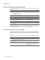
Verify Cisco IOS Software Installed in Bootflash
In addition to the normal system image, verify that the system image(s) on the bootflash device
supports dual GRP operation. Perform the following task, beginning in privileged EXEC mode:
Task
Step 1
Command
List the contents of the bootflash.
If the image supports GRP redundancy, no
further action is needed. (See Table 1.)
Otherwise, continue to the next step.
Step 2
Remove the existing boot image from the
primary GRP.
dir bootflash
-----date/time------ name
Oct 11 1998 19:07:25 gsr-boot-mz.112-15GS2
delete bootflash:gsr-boot-mz.112-14GS1
Note The image filename, gsr-boot-mz.112-14GS1, is
used as an example.
Step 3
Reclaim space on the primary bootflash device.
squeeze bootflash:
Step 4
Copy a replacement Cisco IOS software image
to the primary bootflash device.
copy tftp bootflash:gsr-boot-mz.112-15GS2
Note The image filename, gsr-boot-mz.112-15GS2, is
used as an example.
Install Firmware Upgrades
The system may detect that the hardware contains obsolete firmware for such things as the fabric
loader and the ROM monitor. If you see messages at boot time that warn you of obsolete or older
versions of firmware, install the firmware upgrades before you install the second GRP.
To define the default secondary GRP, perform the following task, beginning in privileged EXEC
mode:
Task
Step 1
Command
Upgrade the GSR firmware.
upgrade { all | image } [ all | slotn ]
GRP Redundant Processor Support 9
Configuration Tasks
Configure Redundancy on the Installed GRP
To configure the installed GRP for redundancy operation, perform the following tasks, beginning in
privileged EXEC mode:
Task
Step 1
Command
Examine auto-sync mode.
show redundancy
If the output contains the line
Auto sync: startup-config
you can skip the remaining steps.
Step 2
Enter global configuration mode.
configure terminal
Step 3
Enter redundancy configuration mode.
redundancy
Step 4
Enter main-CPU redundancy configuration mode.
main-cpu
Step 5
Configure the GRP for standard auto-sync
redundancy operation.
auto-sync startup-config
Step 6
Exit configuration mode.
end
Step 7
Copy the configuration changes to the startup
configuration.
copy running-config startup-config
Use the show redundancy EXEC command to display redundancy information currently configured
on the GRP. Look for the line Auto synch: startup-config in the output.
Prepare the Flash Device for the New GRP
The tasks in this section prepare the Flash device on the new GRP by copying the contents of the
existing GRP Flash device to the new GRP Flash device. The steps below assume that the existing
GRP has a Flash device installed in PCMCIA slot 0 and that the system image file is located on that
device.
To prepare the Flash device for the new GRP, perform the following tasks, beginning in privileged
EXEC mode:
Task
10
Command
Step 1
Perform file maintenance on the Flash device in the
existing GRP and delete any unnecessary files.
del slot0:filename
Step 2
After deleting files, squeeze the Flash device to
optimize free space.
squeeze slot0:
Step 3
Remove the Flash device from the new GRP.
See the GRP installation instructions in the
Gigabit Route Processor Installation and
Configuration note.
Cisco IOS 11.2(15)GS2
Install the New GRP and Boot to ROM Monitor Prompt
Task
Command
Step 4
Install this Flash device into PCMCIA slot 1 on the
existing GRP. If necessary, format the Flash
device.
See the GRP installation instructions in the
Gigabit Route Processor Installation and
Configuration note.
Step 5
Verify that the Flash device in slot 1 contains no
files. If the Flash device contains files, you can
remove them by using either of the following
methods:
del slot1:filename
squeeze slot1:
• To delete a few files, use the del command,
followed by the squeeze command. The squeeze
command optimizes the freed file space.
(or)
format slot1:
• To remove many files quickly, use the format
command.
Step 6
Step 7
Step 8
List all files on Flash device 0 and copy them to
Flash device 1, in the same order that they exist on
Flash device 0.
dir slot0:
Verify that the contents of the two Flash devices
are identical in every aspect. If files are missing or
out of order on Flash device 1, repeat steps 5–7.
dir slot0:
Remove Flash device 1 from the existing GRP and
reinstall it into slot 0 on the new GRP. At this
point, both Flash devices are identical in content.
See the GRP installation instructions in the
Gigabit Route Processor Installation and
Configuration note.
copy slot0:filename slot1:
dir slot1:
Install the New GRP and Boot to ROM Monitor Prompt
To this point, you have completed the following:
•
•
•
Configured the existing GRP to operate in redundant mode.
Copied the contents of the existing GRP Flash device to the new GRP Flash device.
Prepared the new GRP for installation into the router chassis.
To install the new GRP and boot it to the ROM monitor prompt, perform the following task:
Task
Step 1
Command
Remove the existing GRP from the router chassis.
Note This action causes the router to stop switching
packets.
See the appropriate Cisco 12000 series
installation and congfiguration guide, for
example, the Cisco 12012 Installation and
Configuration Guide.
Step 2
Ensure a console terminal is attached to the new
GRP by means of its serial port.
See the GRP installation instructions in the
Gigabit Route Processor Installation and
Configuration note.
Step 3
Insert the GRP into the router.
See the GRP installation instructions in the
Gigabit Route Processor Installation and
Configuration note.
Note Depending on the configuration of the new GRP, it
may boot Cisco IOS software and start IP routing processes.
To prevent this, send a BREAK from the attached console.
Step 4
Observe the GRP boot sequence on the new GRP
and verify the ROM monitor prompt (>) appears
on the console.
If no ROM monitor prompt appears within 60
seconds, send a BREAK from the attached
console.
See the appropriate Cisco 12000 series
Installation and Congfiguration Guide, for
example, the Cisco 12012 Installation and
Configuration Guide.
GRP Redundant Processor Support 11
Configuration Tasks
Boot the Primary and Secondary GRPs in Sequence
For the final phase of preparing your router to operate with redundant processors, you will install
and boot the original (primary) GRP then boot the new (secondary) GRP. To boot the primary and
secondary GRPs in sequence, perform the following tasks:
Task
Command
Step 1
Ensure the original GRP is attached to its dedicated
console port and to its Ethernet connection.
See the GRP installation instructions in the
Gigabit Route Processor Installation and
Configuration note.
Step 2
Insert the original (primary) GRP in the router
chassis. It should boot Cisco IOS software.
At the primary GRP console, verify a Cisco
IOS software image boots. Observe system
boot messages.
Step 3
From the console on the new (secondary) GRP,
issue a boot command to boot Cisco IOS software
on the new GRP.
boot slot0:filename
For example,
boot slot0:gsr-boot-mz.112-15GS2
Note The new GRP will start functioning as the secondary
GRP and its startup configuration will be synchronized with
the primary GRP. The secondary GRP configuration register
will be synchronized with the primary GRP.
When the new, secondary GRP boots, it should be recognized by the primary GRP. If console logging is
enabled, the following message is displayed on the primary and the secodary GRP consoles:
%MBUS-6-GRP_STATUS:GRP in Slot # Mode = MBUS Secondary
Verify Redundant Operation
To verify redundant operation, perform the following task, beginning in EXEC mode:
Task
Command
Step 1
Display redundancy information.
show redundancy
Step 2
Display boot information
show boot
The following excerpt from the show redundancy command shows that a primary and a secondary
GRP are installed and recognized by the router:
show redundancy
Primary
GRP in slot 8:
Secondary GRP in slot 1:
The following excerpt from the show boot command shows that the boot variables (BOOT,
CONFIG_FILE, configuration register) for both GRPs are the same:
show boot
BOOT variable = slot0:gsr-p-mz,1;
CONFIG_FILE variable = nvram:
Current CONFIG_FILE variable = nvram:
Configuration register is 0x2
...
Secondary is in slot 1
Secondary BOOT variable = slot0:gsr-p-mz,1;
Secondary CONFIG_FILE variable = nvram:
Secondary configuration register is 0x2
12
Cisco IOS 11.2(15)GS2
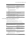
Verify and Update Cisco IOS Software on Secondary GRP
Verify and Update Cisco IOS Software on Secondary GRP
After the system boots with the software that supports GRP redundancy, you can verify and update
the Cisco IOS software on the secondary GRP. Perform the following task, beginning in privileged
EXEC mode:
Task
Step 1
Command
List the contents of the bootflash on the
secondary GRP.
dir sec-bootflash
-----date/time------ name
Oct 11 1998 19:07:25 gsr-boot-mz.112-15GS2
If the image supports GRP redundancy, no
further action is needed. (See Table 1.)
Otherwise, continue to the next step.
Step 2
Remove the existing boot image from the
primary GRP.
delete bootflash:gsr-boot-mz.112-14GS1
Note The image filename, gsr-boot-mz.112-14GS1, is
used as an example.
Step 3
Reclaim space on the primary bootflash device.
squeeze sec-bootflash:
Step 4
Copy a replacement Cisco IOS software image
to the secondary bootflash device.
copy tftp sec-bootflash:gsr-boot-mz.112-15GS2
Note The image filename, gsr-boot-mz.112-15GS2, is
used as an example.
Configuring Software Error Protection Task List
To configure software error protection, the primary GRP and the secondary GRP run different images.
Complete the tasks in the following sections to configure the primary and secondary GRP to run the two
selected images. You must have two GRPs installed in the router and they must be running identical images.
Refer to “Installing Second GRP and Configuring Hardware Backup Task List,” earlier in this
publication.
This feature is not required for normal GRP operations.
Complete the tasks in the following list to configure different images on the primary and secondary
GRP. The first two tasks are required.
•
•
Copy the System Images to Flash Devices
Configure the GRPs to Boot Different Images
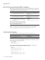
Copy the System Images to Flash Devices
To copy system images to Flash devices, perform the following task, beginning in privileged EXEC
mode:
Task
Command
Step 1
Copy a system image from the TFTP server to the
primary GRP Flash device located in the GRP
PCMCIA slot 0.
copy tftp slot0:name1
Step 2
Specify the TFTP source file, in response to the
Enter source file name: prompt.
Enter source file name:
my_file_system/image1
Step 3
Confirm that the copy should proceed.
13444284 bytes available on device
slot0, proceed? [confirm] y
Step 4
Copy the system image from the TFTP server to
the secondary GRP Flash device located in the
secondary GRP PCMCIA slot 0.
copy tftp sec-slot0:image1
GRP Redundant Processor Support 13
Configuration Tasks
Task
Step 5
Command
Continue using the copy tftp command to copy the
next set of system images into the primary and
secondary Flash devices.
copy tftp slot0:image2
copy tftp sec-slot0:image2
Note We recommend that you maintain identical files in the primary and secondary Flash devices.
Although not strictly required, this simplfies boot image management because both the primary and
secondary Flash devices contain the same sets of system image files.
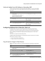
Configure the GRPs to Boot Different Images
In the next task, you configure the primary and secondary GRP to boot different system images. The
task steps assume that the primary GRP is installed in card slot 1 and the secondary GRP is installed
in card slot 2.
Perform the following task, beginning in privileged EXEC mode:
Task
Step 1
Command
Confirm that both GRP cards are operating and the
primary GRP is in redundancy mode. Look for the
following line of output:
show redundancy
Auto synch: startup-config
Step 2
Enter global configuration mode.
configure terminal
Step 3
Configure the primary GRP (installed in slot 1) to
boot image1.
hw-module slot 1 boot system flash
slot0:image1
Step 4
Configure the secondary GRP (installed in slot 2)
to boot image2.
hw-module slot 2 boot system flash
slot0:image2
Step 5
Exit configuration mode.
end
Step 6
Copy the configuration changes to the startup
configuration.
copy running-config startup-config
You can verify that the different boot files are configured for each GRP by using the show boot
EXEC command, as follows:
router# show boot
BOOT variable = slot0:image1,1;
....
Secondary BOOT variable = slot0:image2,1;
....
Managing The Primary and Secondary GRP Task List
The tasks in the following sections show how to manage the primary and secondary GRPs. You can
select and deselect a preferred primary GRP, and configure the router for single-GRP operation.
These tasks are optional:
•
•
•
14
Configure A Preferred Primary
Remove a Preferred Primary Configuration
Revert to Single GRP Operation
Cisco IOS 11.2(15)GS2
Configure A Preferred Primary
Configure A Preferred Primary
The arbitration process determines which GRP will become the primary and which will serve as the
secondary. When the primary GRP and the secondary GRP are configured to boot different system
images, the GRP that boots the most recent version is chosen, by default, as the primary GRP.
However, you can override the arbitration process and specify which GRP will be the primary. To
configure a preferred primary GRP, perform the following task, beginning in privileged EXEC
mode:
Task
Step 1
Command
Specify a preferred primary GRP.
redundancy prefer slot number
Remove a Preferred Primary Configuration
To remove a preferred primary GRP configuration, perform the following task, beginning in
privileged EXEC mode:
Task
Step 1
Command
Remove the primary GRP selection and restore the
default arbitration choice.
redundancy prefer none
Revert to Single GRP Operation
You can revert to single GRP operation in the router and disable the redundant GRP feature.
Determine which GRP to remove from redundant operation. Note the slot number of that GRP,
which you will use when you reconfigure the router for single-GRP operation.
To revert to single-GRP operation, perform the following task, beginning in privileged EXEC mode:
Task
Command
Step 1
Enter configuration mode, selecting the terminal
option.
configure terminal
Step 2
Modify the existing configuration register setting
and specify that the router will boot to ROM
monitor mode.
hw-module slot number config-register 0x0
Step 3
Exit configuration mode.
end
Step 4
Copy the configuration changes to the startup
configuration.
copy running-config startup-config
Step 5
If it is the primary GRP you are removing from
redundant operation, force it to become the
secondary.
redundancy force-failover
Step 6
If it is the secondary GRP you are removing from
redundant operation, force it to reload.
hw-module secondary reload
The unused GRP reloads and remains at the ROM monitor prompt until you remove it from the
router chassis or you reload it by using the ROM monitor boot command. You need not disable a
GRP via the command line interface. Simply removing one of the GRPs will cause the router to
revert to redundant operation. Reverting to single-GRP operation by using the command line
interface is useful when you suspect problems with a GRP but cannot get to the router to pull out the
GRP card.
GRP Redundant Processor Support 15
Configuration Tasks
Monitor and Maintain GRP Redundant Processor Operation Task List
To monitor and maintain GRP redundant processor operation, complete the tasks in the following
sections:
•
•
•
•
Troubleshoot a Failed GRP Card
Display Information about Primary and Secondary GRP Cards
Display Logs for Primary and Secondary GRP Cards
Alphanumeric LED Messages
Troubleshoot a Failed GRP Card
When a new primary GRP card takes over mastership of the router, it automatically reboots the failed
GRP card as the secondary GRP card.
You can also manually reload a failed, inactive GRP card from the primary console. This task returns
the card to the active secondary state. If the primary GRP fails, the secondary will be able to become
the primary. To manually reload the inactive GRP card, perform the following task from global
configuration mode:
Tasks
Command
Reload the inactive secondary GRP card.
hw-module secondary reload
Display Information about Primary and Secondary GRP Cards
You can also display information about both the primary and secondary GRP cards. To do so,
perform any of the following tasks from EXEC mode:
Tasks
Command
Display the environment variable settings and
configuration register settings for both the primary and
secondary GRP cards.
show boot
Show a list of flash devices currently supported on the
router.
show flash devices
Display the software version running on the primary and
secondary GRP card.
show version
Display information about the state of the primary and
secondary GRP cards.
show redundancy
Display Logs for Primary and Secondary GRP Cards
You can display the logging information about the primary and secondary GRP cards. To do so,
perform the following tasks from EXEC mode:
Tasks
Command
Display the logging information for the GRP card in a
specific slot.
show log slot n
The log information shows what activity was occuring on the card at the time of failure.
16
Cisco IOS 11.2(15)GS2
Alphanumeric LED Messages
Alphanumeric LED Messages
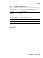
Table 2 shows additional alphanumeric LED messages that may be displayed when a GRP is running
a version of Cisco IOS software that supports GRP redundancy.
Table 2
GRP Redundancy LED Messages
PRI RP
The GRP is the primary and is running normally
SEC RP
The GRP is the secondary and is running normally
SEC ST
The GRP is in secondary startup mode
IOS TRAN
The GRP is in transition from secondary to primary
XS RP
The GRP is in a state of hibernation. This is probably because a version of
Cisco IOS software that does not support GRP redundancy is loaded on one
of the GRPs.
Configuration Example
The following configuration example shows excerpts from a basic GRP redundant processor setup.
Specific configurations for the various interfaces and line cards are ommitted from this example.
!
hostname Router
!
boot system flash slot0:gsr-p-mz
enable password xyzzy
.....
redundancy
main-cpu
auto-sync startup-config
.....
exception core-file /tfpboot/myname/myrouter.core
exception protocol ftp
exception dump 123.45.67.89
exception suffix slot-number
...
ip ftp source-interface Ethernet0
ip ftp username myname
ip ftp password mypassword
ip host myhost 123.45.67.90
...
end
GRP Redundant Processor Support 17
Command Reference
Command Reference
This section documents new or modified commands. All other commands used with this feature are
documented in the Cisco IOS Release 11.3 command references.
•
•
•
•
•
•
•
•
•
•
18
auto-sync
hw-module boot system
hw-module config-register
hw-module secondary reload
main-cpu
redundancy
redundancy force-failover
redundancy prefer
show boot
show redundancy
Cisco IOS 11.2(15)GS2
auto-sync
auto-sync
Use the auto-sync main-CPU redundancy configuration command to define whether the
startup-config, boot variables, and config-register on the secondary GRP will be synchronized to the
values currently stored on the primary GRP. Use the no form of the command to negate an auto-sync
selection.
auto-sync startup-config
no auto-sync
Syntax Description
startup-config
Update the secondary GRP startup configuration whenever the primary
GRP configuration changes.
Default
Auto-sync is performed.
Command Mode
Main-CPU redundancy
Usage Guidelines
This command first appeared in Cisco IOS Release 11.2 GS.
Two GRP cards must be installed in the router for this command to take effect.
All synchronizations move from the primary GRP to the secondary GRP.
An auto-sync between the primary GRP and the secondary GRP happens when the command is
entered. There is a momentary pause at the terminal console while the synchronization occurs.
Whenever the primary GRP startup-config changes, a copy is sent to the secondary startup-config.
The secondary startup-config is also synchronized when the secondary first boots.
The config-register and boot variables on the secondary are also synchronized to values specified in
the startup-config. You can use hw-module global configuration commands to specify different boot
images and config-register settings on the primary and the secondary.
Example
The following example configures synchronization between the primary and secondary GRP:
router(config)# redundancy
router(config-r)# main-cpu
router(config-r-mc)# auto-sync startup-config
Related Commands
main-cpu
redundancy
GRP Redundant Processor Support 19
Command Reference
hw-module boot system
Use the hw-module boot system global configuration command to define system boot parameters
when these are different on the primary GRP and the secondary GRP. Use the no form of this
command to remove the startup system image specification.
hw-module slot number boot system flash [device:][filename]
no hw-module slot number boot system flash [device:][filename]
Syntax Description
flash
This keyword boots the router from a Flash device, as specified by the
device: argument. When you omit all arguments that follow this keyword,
the system searches the PCMCIA slot 0 for the first bootable image.
device:
(Optional) Device containing the system image to load at startup. The
colon (:) is required. Valid devices are as follows:
• bootflash—Internal Flash memory.
• nvram—NVRAM
• slot0—First PCMCIA slot. This device is the default if you do not
specify a device.
• slot1—Flash memory card in the second PCMCIA slot.
filename
(Optional when used with boot system flash) Name of the system image to
load at startup. It is case sensitive. If you do not specify a filename, the
router loads the first valid file in the specified Flash device, the specified
partition of Flash memory, or the default Flash device if you also omit the
device: argument.
Default
The route processor uses the values set by the boot system command, when no other explicit boot
parameters are defined for a particular slot.
The router uses the configuration register settings to determine the default system image filename.
The router forms the default boot filename by starting with the word cisco and then appending the
octal equivalent of the boot field number in the configuration register, followed by a hyphen (-) and
the processor type name (cisconn-cpu). See the appropriate hardware installation guide for details
on the configuration register and default filename. See also the hw-module config-register
command.
Command Mode
Global configuration
Usage Guidelines
This command first appeared in Cisco IOS Release 11.2 GS.
For this command to work, the config-register command must be set properly.
Use this command to specify different boot images for the primary GRP and the secondary GRP.
20
Cisco IOS 11.2(15)GS2
hw-module boot system
You can also enter several boot system commands to provide a fail-safe method for booting your
router. The router stores and executes the boot system commands in the order in which you enter
them in the configuration file. If you enter multiple boot commands of the same type, the router tries
them in the order in which they appear in the configuration file. If a boot system command entry in
the list specifies an invalid device, the router skips that entry.
Example
The following example instructs the GRP in chassis slot 3 to boot from an image located on the Flash
memory card inserted in PCMCIA slot 0, and the GRP in chassis slot 0 to boot a different image
located on its Flash memory card:
hw-module slot 3 boot system flash slot0:gsr-p-mz
hw-module slot 0 boot system flash slot0:gsr-p-mz.new
Related Commands
hw-module config-register
GRP Redundant Processor Support 21
Command Reference
hw-module config-register
Use the hw-module config-register global configuration command to define different system
configuration register parameters for the primary GRP and the secondary GRP. Use the no version
of the command to restore default configuration register parameters.
hw-module slot number config-register hex-number
no hw-module slot number config-register
Syntax Description
number
Slot number where the GRP is installed.
hex-number
Register number value between 0x0 and 0xFF.
Default
When no parameters are modified by using this command, the values configured via the
config-register global configuration command.
Command Mode
Global configuration
Usage Guidelines
This command first appeared in Cisco IOS Release 11.2 GS.
Use this command to set the configuration registers to different values on the primary or secondary
GRP. You need not use this command when you want the same values on both the primary and
secondary GRP.
Example
The following example sets the configuration register for the GRP installed in chassis slot 3:
hw-module slot 3 config-register 0x02
Related Commands
hw-module boot system
22
Cisco IOS 11.2(15)GS2
hw-module secondary reload
hw-module secondary reload
Use the hw-module secondary reload EXEC command to reload the designated secondary GRP.
hw-module secondary reload
Syntax Description
This command has no keywords or arguments.
Default
None
Command Mode
Privileged EXEC
Usage Guidelines
This command first appeared in Cisco IOS Release 11.2 GS.
When the secondary GRP is reloaded, there is no interruption to the primary GRP activity. The
secondary GRP will boot to whatever level is set by means of the configuration register (for example,
only to ROM monitor prompt).
This command executes immediately and does not ask for confirmation.
Example
The following example reloads the secondary GRP from the configuration specified by the cards
boot variables and configuration settings:
hw-module secondary reload
*Oct 2 10:20:36.866: %MBUS-6-MGMTSECRELOAD: Secondary in slot 1 reloaded by operator
command
%MBUS-6-GRP_STATUS: GRP in Slot 1 Mode = MBUS Secondary
Related Commands
redundancy prefer
GRP Redundant Processor Support 23
Command Reference
main-cpu
Use the main-cpu redundancy configuration command to enter main-CPU configuration mode.
main-cpu
Syntax Description
This command has no keywords or arguments.
Default
None
Command Mode
Redundancy
Usage Guidelines
This command first appeared in Cisco IOS Release 11.2 GS.
It is not necessary to have two GRP cards installed in the router before you use this command.
Example
The following example shows how to enter main-CPU configuration mode:
router(config-r)# main-cpu
Related Commands
configure
24
Cisco IOS 11.2(15)GS2
redundancy
redundancy
Use the redundancy global configuration command to enter redundancy configuration mode.
redundancy
Syntax Description
This command has no keywords or arguments.
Default
None
Command Mode
Global
Usage Guidelines
This command first appeared in Cisco IOS Release 11.2 GS.
It is not necessary to have two GRP cards installed in the router before you use this command.
After you enter redundancy configuration mode, you can enter the main-cpu command. The
main-cpu command places you in the main-CPU redundancy configuration mode, which allows you
to specify CPU redundancy characteristics.
Example
The following example enters redundancy configuration mode:
router(config)# redundancy
Related Commands
configure
redundancy force-failover
redundancy prefer
GRP Redundant Processor Support 25
Command Reference
redundancy force-failover
Use the redundancy force-failover EXEC command to force the secondary GRP to become the
primary GRP.
redundancy force-failover
Syntax Description
This command has no keywords or arguments.
Default
None
Command Mode
Privileged EXEC
Usage Guidelines
This command first appeared in Cisco IOS Release 11.2 GS.
The router is interrupted while the processing services are enabled on the newly established primary
GRP.
The secondary, as part of the process of taking over as the new primary, resets the old primary.
The following list suggests a few situtations where you might use the redundancy force-failover
command:
•
Prior to removing a primary GRP for maintenance. You may want to force the secondary to take
over operation as the primary GRP.
•
After loading a new software image on the secondary. You can force the new software to run,
leaving a prior version of software on the old primary as backup.
•
When remotely testing failover operation on a system. You can force a failover by using the
redundancy force-failover command, rather than physically pulling the primary GRP out of the
router.
Example
The following example forces the secondary GRP to become the primary GRP:
redundancy force-failover
Proceed with failover? [confirm]n
Pressing the enter key or a y accepts the action. Press n to disallow the action.
Related Commands
redundancy
26
Cisco IOS 11.2(15)GS2
redundancy prefer
redundancy prefer
Use the redundancy prefer EXEC command to define which card slot in a Cisco 12000 will contain
the preferred primary GRP.
redundancy prefer { none | slot number }
Syntax Description
none
Allows any slot in a Cisco 12000 to contain the primary GRP.
slot number
Defines which slot contains the preferred primary GRP. The value for
number is any valid card slot in the Cisco 12000.
Default
None
Command Mode
Privileged EXEC
Usage Guidelines
This command first appeared in Cisco IOS Release 11.2 GS.
Use this command when you wish to override the arbitration scheme for determining which slot
contains the primary GRP, or to explicitly define which slot contains the primary GRP.
Use this command to define a preference for the slot that contains the primary GRP. The arbitration
scheme considers this preference, however, defining a preference does not guarantee that preference
will be observed. Under normal circumstances, a GRP in the preferred slot will become the primary.
The arbitration scheme may overide that preference should the preference conflict with other
arbitration data. For example, if the GRP in the preferred slot is new to the chassis and likely to have
an inappropriate startup-config, the other GRP will instead become the primary.
If no GRP is installed in the preferred slot, the arbitration scheme determines which GRP will be
primary.
When you specify redundancy prefer none, the backplane NVRAM is initialized and existing
values are stored.
Example
The following example defines card slot 8 as containing the primary GRP:
redundancy prefer slot 8
Related Commands
redundancy
GRP Redundant Processor Support 27
Command Reference
show boot
Use the show boot EXEC command to display GRP boot information.
show boot
Syntax Description
This command has no keywords or arguments.
Default
None
Command Mode
Privileged EXEC
Usage Guidelines
This command first appeared in Cisco IOS Release 11.0.
Example
The following example displays boot information:
show boot
BOOT variable = slot0:gsr-p-mz,1;
CONFIG_FILE variable = nvram:
Current CONFIG_FILE variable = nvram:
Configuration register is 0x2
CHASSIS_SN variable = 66300963
CONFGEN variable = 419
Secondary
Secondary
Secondary
Secondary
Secondary
Secondary
is in slot 1
BOOT variable = slot0:gsr-p-mz,1;
CONFIG_FILE variable = nvram:
configuration register is 0x2
CHASSIS_SN variable = 66300963
CONFGEN variable = 419
Table 3 describes selected fields from the show boot command output.
Table 3
28
Show Boot Field Descriptions
Field
Description
BOOT variable = slot0:gsr-p-mz,1;
Location and name of the software image that will boot on the primary GRP.
CONFIG_FILE variable = nvram:
Location of the router configuration file.
Current CONFIG_FILE variable =
nvram:
Current value of the CONFIG_FILE variable.
Configuration register is 0x2
Current content of the configuration register.
CHASSIS_SN variable = 66300963
Serial number of the Cisco 12000 router chassis in which the GRP was
installed when the startup-config was saved.
Cisco IOS 11.2(15)GS2
show boot
Table 3
Show Boot Field Descriptions (Continued)
Field
Description
CONFGEN variable = 419
Configuration sequence number stamp from the Cisco 12000 router chassis in
which the GRP was installed when the startup-config was saved.
Secondary is in slot 1
Location of secondary GRP.
Secondary BOOT variable =
slot0:gsr-p-mz,1;
Location and name of the software image that will boot on the secondary
GRP.
Secondary CONFIG_FILE variable =
nvram:
Location of the router configuration file that the secondary GRP will load.
Secondary BOOTLDR variable =
Current value of the BOOTLDR variable.
Secondary configuration register is
0x2
Current content of the configuration register.
Secondary CHASSIS_SN variable =
66300963
Serial number of the Cisco 12000 router chassis in which the GRP was
installed when the startup-config was saved.
Secondary CONFGEN variable =
419
Configuration sequence number stamp from the Cisco 12000 router chassis in
which the GRP was installed when the startup-config was saved.
Related Commands
hw-module config-register
redundancy prefer
GRP Redundant Processor Support 29
Command Reference
show redundancy
Use the show redundancy EXEC command to display redundancy status information.
show redundancy [ all | arbitration | secondary | trace [ all | latest ] ]
Syntax Description
all
(Optional) Display all redundancy information.
arbitration
(Optional) Display details of arbitration mechanism.
secondary
(Optional) Display details of current secondary GRP.
trace
(Optional) Display trace of arbitration mechanism.
Note The trace option is intended for use by qualified technical support
personnel.
all
(Optional) Display all available trace information. This is the default for
the show redundancy trace command.
latest
(Optional) Display only most recent trace information.
Default
None
Command Mode
Privileged EXEC
Usage Guidelines
This command first appeared in Cisco IOS Release 11.2 GS.
When used with no keywords, this command displays a basic summary of GRP redundancy status.
The all keyword displays all available information. Use the arbitration, secondary, or trace
keywords to display selected subsets of GRP redundancy status.
You cannot combine keywords.
Examples
The following example displays basic GRP redundancy information from the Cisco 12000:
show redundancy
Primary
GRP in slot 2:
Secondary GRP in slot 1:
Preferred GRP: none
Auto synch: startup-config
30
Cisco IOS 11.2(15)GS2
show redundancy
The following example displays arbitration GRP redundancy information in the Cisco 12000:
show redundancy arbitration
Primary
GRP in slot 2:substate = p_redundant
Secondary GRP in slot 1:
Choice of primary due to failover initiated by primary in slot 1
Reason for failover:crash
Preferred GRP: none
Chassis holds: chassis s/n 66300963
config stamp 496
Local GRP holds:chassis s/n 66300963
config stamp 496
Information from last arbitration period:
GRP Slot 1:
chassis s/n 66300963
config stamp 495
IOS 11.2 redundancy v3 date 1998-10-14
Mem size 128M GRP s/n CAB0147001B
GRP Slot 2:
chassis s/n 66300963
config stamp 495
IOS 11.2 redundancy v3 date 1998-10-14
Mem size 128M GRP s/n 04496038
known:
1 2
allowed:
0 1 2 3 4 5 6 7 8 9 10 11
preferred:
compatible
1 2
chassis_match: 1 2
cfg_stamp_match:1 2
latest_cfg:
latest_ios:
1 2
largest_mem:
1 2
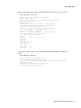
The following example displays basic secondary GRP redundancy information from the Cisco
12000:
show redundancy secondary
Version information for secondary in slot 1:
Cisco Internetwork Operating System Software
IOS (tm) GS Software (GSR-P-M), Experimental Version 11.2(19980829:002140)
[ghall-bfr_112 2063]
Copyright (c) 1986-1998 by cisco Systems, Inc.
Compiled Wed 14-Oct-98 02:30 by ghall
GRP Redundant Processor Support 31
Command Reference
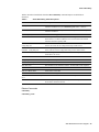
The following example displays all GRP redundancy information from the Cisco 12000:
show redundancy all
Primary
GRP in slot 8: substate = p_redundant
Secondary GRP in slot 1:
Choice of primary due to arbitration judgement of this GRP
no other GRP
Preferred GRP: 9
Allowed
GRPs: 0 1 2 3 4 5 6 7 8 9 10 11
Chassis holds:
chassis s/n 66300963
config stamp 419
Local GRP holds: chassis s/n 66300963
config stamp 419
Information from last arbitration period:
GRP Slot 1:
chassis s/n 66300963
config stamp 418
IOS arb ver 2 date 1998-10-01
Mem size 128M GRP s/n CAB0147001B
GRP Slot 8:
chassis s/n 66300963
config stamp 418
IOS 11.2 redundancy v3 date 1998-10-01
Mem size 32M GRP s/n 04496038
known:
1 8
preferred:
9
compatible
1 8
chassis_match:
1 8
cfg_stamp_match: 1 8
latest_cfg:
latest_ios:
1 8
largest_mem:
1
NOTICE Unequal GRP memory sizes: 32M in slot 8, 128M in slot 1
Auto synch: startup-config
Version information for secondary in slot 1:
Cisco Internetwork Operating System Software
IOS (tm) GS Software (GSR-P-M), Experimental Version 11.2(19980829:002140)
[ghall-bfr_112 2063]
Copyright (c) 1986-1998 by cisco Systems, Inc.
Compiled Wed 14-Oct-98 02:30 by ghall
State Machine Latest Events:
-- (Current Time is 40287.000)
|
Timestamp | State
Substate
|
40274.260 | primary
p_redundant
|
40274.632 | primary
p_redundant
|
40274.760 | primary
p_redundant
State Machine Significant Events:
-- (Current Time is 40324.856)
|
Timestamp | State
Substate
|
7.440 | arb
a_alone
|
| primary
p_judge
|
7.552 | primary
p_judge
|
| primary
p_standalone
|
17.136 | primary
p_standalon
|
347.804 | primary
p_standalon
|
347.808 | primary
p_standalon
|
348.928 | primary
p_standalon
|
| primary
p_redundant
|
38329.840 | primary
p_redundant
|
39531.056 | primary
p_redundant
32
Cisco IOS 11.2(15)GS2
Event
MSG_SECONDARY
TICK_COUNTDOWN
MSG_SECONDARY
Count
20
19
20
Event
TICK_EXPIRY
Count
0 ->
DECIDED_STANDALONE
0 ->
MGMT_DEBUG_CHANGE
MSG_BETTER_BID
MSG_BETTER_BID
DECIDED_PRIMARY
0
0
0
20 ->
DECIDED_PRIMARY
operator reload
20
4 ->
show redundancy
Table 4 describes selected fields from the show redundancy command output. Not all fields are
described.
Table 4
Show Redundancy Field Descriptions
Field
Description
Primary GRP in slot 8
Slot containing the primary GRP. The primary slot is determined either by the
arbitration mechanism or by the redundancy prefer EXEC command.
Secondary GRP in slot 1
Slot containing the secondary GRP. The secondary slot is determined by the
arbitration mechanism
Choice of primary due to ...
Reason for selecting primary GRP.
Preferred GRP: 9
Preferred primary GRP, selected by the redundancy prefer EXEC command.
In this instance, no GRP is installed in slot 9 so the arbitration mechanism
selected an alternative primary GRP.
Chassis holds: chassis s/n 66300963
config stamp 419
The Cisco 12000 has chassis serial number shown and the last configuration
saved in this chassis has the configuration stamp number shown.
Local GRP holds: chassis s/n
66300963 config stamp 419
The startup configuration on this GRP was saved in chassis serial number
shown, when the chassis configuration stamp was the number shown.
GRP Slot 1:
Slot containing the first found GRP. Slot information is repeated for each
found GRP in the chassis.
chassis s/n 66300963
Serial number of the Cisco 12000 chassis.
config stamp 418
Configuration stamp identifier.
IOS 11.2 redundancy v3
Software version identifier.
date 1998-10-01
Date identifier for the arbitration software. The date field is Y2K compliant.
Mem size 128M
Amount of memory installed on this GRP.
GRP s/n CAB0147001B
Serial number of this GRP.
NOTICE ...
Informational message.
Version information for secondary in
slot 1:
Cisco IOS software header information for secondary GRP.
WARNING ...
Indicates a potential problem, such as a preferred slot is specified for a GRP
but no GRP is detected in that slot.
Related Commands
redundancy
redundancy prefer
GRP Redundant Processor Support 33
Debug Commands
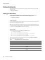
Debug Commands
This section describes debug commands and test commands useful for troubleshooting the GRP
redundancy feature.
•
debug gsr redundancy
debug gsr redundancy
Use the debug gsr redundancy debug command to display information about the status of
redundancy operations. The no form of this command disables debugging output.
[no] debug gsr redundancy
Usage Guidelines
Use this command to display continuous output of the various state changes and messages that pass
between the primary GRP and secondary GRP.
Note Using this command places a high load on the route processor. We recommend that you do
not use this command in a production network. The debug information displayed by this command
is available from the show redundancy trace EXEC command.
Sample Display
The following display shows sample debug gsr redundancy output.
router#
*Feb 25
*Feb 25
*Feb 25
*Feb 25
*Feb 25
debug gsr redundancy
12:55:30.998:redundancy:send msg_primary
12:55:30.998:redundancy:primary p_redundant, TICK_COUNTDOWN:
12:55:30.998:redundancy:enq MSG_SECONDARY
12:55:30.998:redundancy:primary p_redundant, MSG_SECONDARY:
12:55:31.498:redundancy:enq TICK_COUNTDOWN
Table 5 shows describes the fields and messages shown in the sample debug gsr redundancy
output. Not all fields or values are described.
Table 5
34
Debug GSR Redundancy Field Descriptions
Field
Description
Oct 2 11:28:08.737:
Date and time on the router.
redundancy
GSR redundancy debug message.
send msg_primary
Recipient of current message.
primaryp_redundant . . .
Change in the primary GRP arbitration finite state
machine.
enq . . .
Change in the secondary GRP arbitration finite state
machine.
Cisco IOS 11.2(15)GS2