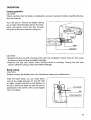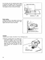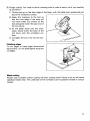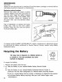
1
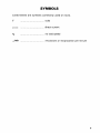
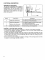
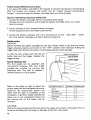
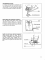
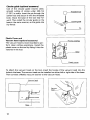
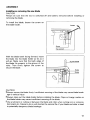
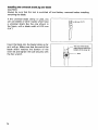
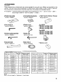
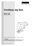
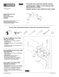
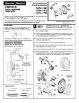
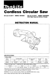
Cordless Jig Saw
MODEL 4331DZ
MODEL 4331DWD
MODEL 4333DZ
MODEL 4333DWD
INSTRUCTION MANUAL
Model
Battery
Voltage
4331D
12.0 v
4333D
14.4 V
Length
of stroke
""
(1")
Aluminum
Strokes
per minute
Overall
length
$
;
:
(
;
)
500-2,800
2~~~~
Max. cuning capacities
Wood
Mild Steel
(2.114")
lo"
(3/8")
~
Net
weight
2.6 kg
(5.7 Ibs)
2.9 kg
f f i 3 Ihsl
Battery Cartridge 1234 IModel DC1411 High Capacity Battery Charger
Voltaae
12.0 v
Voltage
I
I
Input
I
OUtDUt
I
Charging time
A.C. only 50 Hz - 60 Hz
D.C. 7.2 V - 14.4 V
60 min.
Input
output
Charging time
* Manufacturer reserves the right to change specifications without notice.
* Note: Specifications may differ from country to country.
WARNING: For your personal safety. READ and UNDERSTAND before using.
SAVE THESE INSTRUCTIONS FOR FUTURE REFERENCE.
GENERAL SAFETY RULES
(For All Battery Operated Tools)
WARNING! Read and understand all instructions. Failure
to follow all instructions listed below, may result in electric
shock, fire and/or serious personal injury.
SAVE THESE INSTRUCTIONS
Work Area
Keep your work area clean and well lit. Cluttered benches and dark areas invite
accidents.
Do not operate power tools in explosive atmospheres, such as in the presence
of flammable liquids, gases, or dust. Power tools create sparks which may ignite
the dust or fumes.
Keep bystanders, children, and visitors away while operating a power tool.
Distractions can cause you to lose control.
Electrical Safety
A battery operated tool with integral batteries or a separate battery pack must
be recharged only with the specified charger for the battery. A charger that
may be suitable for one type of battery may create a risk of fire when used with
another battery.
Use battery operated tool only with specifically designated battery pack. Use
of any other batteries may create a risk of fire.
Personal Safety
Stay alert, watch what you are doing, and use common sense when operating
a power tool. Do not use tool while tired or under the influence of drugs, alcohol,
or medication. A moment of inattention while operating power tools may result
in serious personal injury.
Dress properly. Do not wear loose clothing or jewelry. Contain long hair. Keep
your hair, clothing, and gloves away from moving parts. Loose clothes, jewelry,
or long hair can be caught in moving parts.
Avoid accidental starting. Be sure switch is in the locked or off position before
inserting battery pack. Carrying tools with your finger on the switch or inserting
the battery pack into a tool with the switch on invites accidents.
Remove adjusting keys or wrenches before turning the tool on. A wrench or
a key that is left attached to a rotating part of the tool may result in personal injury.
Do not overreach. Keep proper footing and balance at all times. Proper footing
and balance enable better control of the tool in unexpected situations.
Use safety equipment. Always wear eye protection. Dust mask, non-skid safety
shoes, hard hat, or hearing protection must be used for appropriate conditions.
2
Tool Use and Care
Use clamps or other practical way t o secure and support the workpiece t o a
stable platform. Holding the work by hand or against your body is unstable and
may lead t o loss of control.
Do not force tool. Use the correct tool for your application. The correct tool
will do the job better and safer a t the rate for which it is designed.
* D o not use tool if switch does not turn it on or off. A tool that cannot be
controlled with the switch is dangerous and must be repaired.
Disconnect battery pack from tool or place the switch in the locked or off
position before making any adjustments, changing accessories, or storing the
tool. Such preventive safety measures reduce the risk of starting the tool
accidentally.
Store idle tools out of reach of children and other untrained persons. Tools are
dangerous in the hands of untrained users.
When battery pack is not in use, keep it away from other metal objects like:
paper clips, coins, keys, nails, screws, or other small metal objects that can
make a connection from one terminal t o another. Shorting the battery terminals
together may cause sparks, burns, or a fire.
Maintain tools with care. Keep cutting tools sharp and clean. Properly maintained
tools with sharp cutting edge are less likely to bind and are easier to control.
Check for misalignment or binding of moving parts, breakage of parts, and any
other condition that may affect the tool's operation. If damaged, have the tool
serviced before using. Many accidents are caused by poorly maintained tools.
Use only accessories that are recommended by the manufacturer for your
model. Accessories that may be suitable for one tool may create a risk of injury
when used on another tool.
Service
Tool service must be performed only by qualified repair personnel. Service or
maintenance performed by unqualified personnel may result in a risk of injury.
When servicing a tool, use only identical replacement parts. Follow instructions
in the Maintenance section of this manual. Use of unauthorized parts or failure
t o follow Maintenance Instructions may create a risk of shock or injury.
3
Specific Safety Rules
1. Hold tool by insulated gripping surfaces when performing an operation where
the cutting tool may contact hidden wiring. Contact with a "live" wire will
also make exposed metal parts of the tool "live" and shock the operator.
2. Be aware that this tool is always in an operating condition because it does
not have t o be plugged into an electrical outlet.
3.Avoid cutting nails. Inspect for and remove all nails from the workpiece before operation.
4. Do not cut hollow pipe.
5. Do not cut oversize workpiece.
6. Check for the proper clearance beneath the workpiece before cutting so that
the blade will not strike the floor, workbench, etc.
7. Hold the tool firmly.
8. Check the blade is not contacting the workpiece before the switch is turned
on.
9. Keep hands away from moving parts.
IO. When cutting through walls, floors or wherever "live" electrical wires may
be encountered, DO NOT TOUCH ANY METAL PARTS OF THE TOOL!
Hold the tool only by the plastic handle t o prevent electric shock if you cut
through a "live" wire.
11. Do not leave the tool running. Operate the tool only when hand-held.
12. Always switch off and wait for the blade t o come t o a complete stop before
removing the blade from the workpiece.
13. Do not touch the blade or the workpiece immediately after operation; they
may be extremely hot and could burn your skin.
SAVE THESE INSTRUCTIONS.
4
SYMBOLS
Listed below are symbols commonly used on tools.
v
...................................
- ...................................
volts
direct current
n,
...................................
no load speed
.../min
...................................
revolutions or reciprocation per minute
5
ADDITIONAL SAFETY RULES
FOR CHARGER & BATTERY CARTRIDGE
1. Do not charge Battery Cartridge when temperature is BELOW 10°C (5OOF)
or ABOVE 4OoC (104OF).
2. Do not attempt t o use a step-up transformer, an engine generator or DC power
receptacle.
3.Do not allow anything t o cover or clog the charger vents.
4. Always cover the battery terminals w i t h the battery cover when the battery
cartridge is not used.
5. A battery short can cause a large current flow, overheating, possible burns
and even a breakdown.
(11 Do not touch the terminals with any conductive material.
(2) Avoid storing battery cartridge in a container with other metal objects such
as nails, coins, etc.
(3)Do not expose battery cartridge t o water or rain.
6. Do not store the tool and Battery Cartridge in locations where the temperature may reach or exceed 5OoC (122OF).
7. Do not incinerate the Battery Cartridge even if it is severely damaged or is
completely worn out. The battery cartridge can explode in a fire.
SAVE THESE INSTRUCTIONS.
6
IMPORTANT SAFETY INSTRUCTIONS
FOR CHARGER &
BATTERY CARTRIDGE
1. SAVE THESE INSTRUCTIONS - This manual
contains important safety and operating instructions for battery charger.
2.Before using battery charger, read all instructions and cautionary markings
on (1) battery charger, (2)battery, and (3)product using battery.
3.CAUTION - To reduce risk of injury, charge only MAKITA Battery Cartridge
7000,7001,7002,7033,7100,7120,9000,9001,9002,9033,9100,
9101,9102,9120,9122,9133,1200.
1201,1202,1210,1211,1222,1233,
I422,1433,9101A,
9102A.1201A or 1202A.Other types of batteries may
burst causing personal injury and damage.
4.Do not expose charger t o rain or snow.
5.Use of an attachment not recommended or sold by the battery charger
manufacturer may result in a risk of fire, electric shock, or injury t o persons.
6.To reduce risk of damage t o electric plug and cord, pull by plug rather than
cord when disconnecting charger.
7.Make sure cord is located so that it will not be stepped on, tripped over, or
otherwise subjected t o damage or stress.
8.A n extension cord should not be used unless absolutely necessary. Use of
improper extension cord could result in a risk of fire and electric shock. If
extension cord must be used, make sure:
a. That pins on plug of extension cord are the same number, size, and shape
as those of plug on charger;
b. That extension cord is properly wired and in good electrical condition; and
c. That wire size is at least as large as the one specified in the table below.
TABLE 1
RECOMMENDED MINIMUM AWG SIZE FOR
EXTENSION CORDS FOR BATTERY CHARGERS
Length of Cord (Feet)
AWG Size of Cord
9.
IO.
11.
12.
25
18
50
18
100
18
150
16
FUNCTIONAL DESCRIPTION
Selecting the cutting action
This tool can be operated with an orbital or
a straight line cutting action. To change the
cutting action, just turn the lever to the
desired cutting action position. Refer to the
table below to help determine the appropriate cutting action.
Cutting action
Position
0
I
Straight linecutting action
I
I
II
I
~
Applications
For cutting mild steel, stainless steel and plastics.
For clean cuts in wood and plywood.
Small orbit cutting action
I
For cutting mild steel, aluminum and hard wood.
For cutting wood and plywood.
For fast cutting in aluminum and mild steel.
I
I
For fast cutting in wood and plywood.
I
Medium Orbit cutting action
1
111
~
Large orbit cutting action
~
~
~
~
~
Installing or removing battery cartridge
Always switch off the tool before insertion or removal of the battery cartridge.
.To remove the battery cartridge, withdraw it from the tool while pressing the
buttons on both sides of the cartridge.
To insert the battery cartridge, align the tongue on the battery cartridge with the
groove in the housing and slip it into place. Always insert it all the way until it locks
in place with a click. If not, it may accidentally fall out of the tool, causing injury to
you or someone around you.
Do not use force when inserting the battery cartridge. If the cartridge does not slide
in easily, it is not being inserted correctly.
8
Charging
Your new battery cartridge is not
charged. You will need t o charge it
before use. Use the high capacity battery
charger Model DC1411 to charge the
battery cart ridge.
Charging light
Plug the high capacity battery charger
into the proper A.C. voltage source. The
charging light will flash in green color.
Insert the battery cartridge so that the
plus and minus terminals on the battery
cartridge are on the same sides as their
respective markings on the high capacity
battery charger. Insert the cartridge fully into the port so that it rests on the
charger port floor.
When the battery cartridge is inserted, the charging light color will change from
green to red and charging will begin. The charging light will remain lit steadily
during charging. When the charging light color changes from red to green, the
charging cycle is complete. The charging time is approximately one hour.
If you leave the battery cartridge in the charger after the charging cycle is complete,
the charger will switch into its "trickle charge (maintenance charge)" mode which
will last approximately 24 hours.
After charging, unplug the charger from the power source.
CAUTION:
The high capacity battery charger Model DC1411 is for charging Makita battery
cartridge. Never use it for other purposes or for other manufacturer's batteries.
When you charge a new battery cartridge or a battery cartridge which has not been
used for a long period of time, it may not accept a full charge. This is a normal
condition and does not indicate a problem. You can recharge the battery cartridge
fully after discharging it completely and recharging a couple of times.
If you charge a battery cartridge from a just-operated tool or a battery cartridge
which has been left in a location exposed to direct sunlight or heat for a long time,
the charging light may flash a red color. If this occurs, wait for a while. Charging
will begin after the battery cartridge cools. The battery cartridge will cool faster if
you remove the battery cartridge from the high capacity battery charger.
If the charging light flashes alternately in green and red color, a problem exists and
charging is not possible. The terminals on the charger or battery cartridge are
clogged with dust or the battery cartridge is worn out or damaged.
9
Trickle charge (Maintenance charge)
If you leave the battery cartridge in the charger to prevent spontaneous discharging
after full charge, the charger will switch into its "trickle charge (maintenance
charge)" mode and keep the battery cartridge fresh and fully charged.
Tips for maintaining maximum battery life
1. Charge the battery cartridge before completely discharged.
Always stop tool operation and charge the battery cartridge when you notice
less tool power.
2. Never recharge a fully charged battery cartridge.
Overcharging shortens the battery service life.
3. Charge the battery cartridge with room temperature at 10°C - 40°C (50°F - 104°F).
Let a hot battery cartridge cool down before charging it.
Switch action
CAUTION:
Before inserting the battery cartridge into the tool, always check to see that the switch
trigger actuates properly and returns to the "OFF" position when released. Pulling the
trigger hard when the lock off button is not pressed causes switch damage.
To start the tool, simply push the lock off
button then pull the trigger. Release the
trigger to stop.
Speed adjusting dial
L o c k 4 button
I
Speed adjusting dial
The tool speed can be adjusted and
maintained between 500 and 2,800
strokes per minute by turning the
adjusting dial. The dial is marked 1
(lowest speed) t o 5 (full speed).
Refer to the table at right t o Select the
proper speed for the workpiece t o be cut.
However, the appropriate speed may
differ with the type or thickness of the
workpiece. In general, higher speeds will
allow you t o cut workpieces faster but
the service life of the blade will be
Workpiece t o b e cut
N u m b e r o n adjusting dial
Wood
3-5
M i l d steel
3-5
Stainless steel
3-4
Aluminum
2-3
Plastics
1-4
CAUTION:
Adjust the speed adjusting dial only within the range of numbers 1 through 5. Do not
force the dial beyond this range or damage to the tool may result.
10
Anti-splintering device
To reduce the potential for workpiece surface splintering, the anti-splintering device
can be used. Fit it into the base from below
so that it surrounds the sides of the blade.
-
Plastic base plate (optional accessory)
Use the plastic base plate when cutting
decorative veneers, plastics, etc. It protects
sensitive or delicate surfaces from damage.
To replace the base plate, remove the four
screws with the hex wrench.
I
I
Guide rule (rip fence; optional accessory)
When cutting widths of under 150 mm
(5-29/32”) repeatedly, use of the guide rule
will assure fast, clean, straight cuts. To
install it, loosen the bolt on the front of the
base. Slip in the guide rule and secure the
bolt.
I
11
Circular guide (optional accessory)
Use of the circular guide insures clean,
smooth cutting of circles under 200 mm
(7-7/8")
in radius. Insert the pin through the
center hole and secure it with the threaded
knob. Move the base of the tool fully forward. Then install the circular guide on the
base in the same manner, as the guide rule
(rip fence).
c---
Threaded knob
Plastic Cover and
Vacuum head (optional accessory)
The vacuum head is recommended to perform clean cutting operations. Install the
plastic cover on the tool by fitting it into the
notches in the tool.
Fit into notches
Base
L l
Plastic cover
To attach the vacuum head on the tool, insert the hooks of the vacuum head into the
holes in the base. The vacuum head can be installed on either left or right side of the base.
Then connect a Makita vacuum cleaner to the vacuum head.
.,
Vacuum
head
Base
12
1
ASSEMBLY
Installing or removing the saw blade
CAUTION:
Always be sure that the tool is switched off and battery removed before installing or
removing the blade.
To install the blade, loosen the screw on
the blade holder.
Loosen
screw
I
Hex wrench
With the blade teeth facing forward, insert
the blade into the blade holder as far as it
will go. Make sure that the back edge of
the blade fits properly in the groove of the
roller. Then firmly tighten the screw to
secure the blade.
CAUTION:
Always secure the blade firmly. Insufficient securing of the blade may cause blade breakage or serious injury.
Always clean out the blade holder before installing the blade. Chips or foreign matter on
the blade holder may cause insufficient securing of the blade.
Use a lubricant or cutting oil between the blade and roller when cutting iron or composition board, etc. Failure to do so will shorten the service life of your blade and roller or lead
to potentially dangerous blade breakage.
13
Installing the universal shank jig saw blade
CAUTION:
Always be sure that the tool is switched off and battew removed before installing
removing the blade.
If the universal blade clamp is used, you
can use blades of other makes which have
a universal shank like the one shown in
the figure, with a blade width of 6.35 mm
( 1/4").
Insert the blade into the blade holder as far
as it will go. Make sure that the end of the
blade shank reaches the bottom of the
inner slit and tighten the bolt securely with
the hex wrench.
14
6.35m m (1/4')
The end of the blade
shank should reach the
OPERATION
Cutting operation
CAUTION:
Check carefully that the blade is adequately secured in position before inserting the battery into the tool
Turn the tool on without the blade making
any contact. Rest the base flat on the workpiece and gently move the tool forward
along the previously marked cutting line.
I -
I
t J
Base
Cutting line
I
CAUTION:
*Always hold the tool with the base flush with the workpiece. Failure to do so may cause
a slanted cutting surface and blade breakage.
*Advance the tool very slowly when cutting curves or scrolling. Forcing the tool may
cause a slanted cutting surface and blade breakage.
Bevel cutting
CAUTION:
Always remove the battery from the tool before making any adjustments
With the base tilted, you can make bevel
cuts at any angle between 0" and 45" (left
or right). Loosen the bolt on the bottom of
the tool. Move the base so that the bolt is
positioned in the center of the cross-shaped
slot in the base.
I
I
15
Tilt the base until the desired bevel anale
is obtained. The edge of the motor housing
indicates the bevel angle by graduations.
Then tighten the bolt to secure the base.
I
F , g e , o f motor housing
Graduations
Flush cutting
Loosen the bolt on the bottom of the tool
and slide the base all the way back. Then
tighten the bolt to secure the base.
cutouts
Cutouts can be made with either of two methods A or B.
A) Boring a starting hole: For internal cutouts without lead-in cut from an edge,
pre-drill a starting hole more than
12 mm (15/32") in diameter. Insert the
blade into this hole and hold the tool
firmly against the workpiece to start
your cut.
16
,
I I
Base
B) Plunge cutting: You need not bore a starting hole or make a lead-in cut if you carefully
do as follows.
1) Tilt the tool up on the front edge of the base, with the blade point positioned just
above the workpiece surface.
2) Apply firm pressure to the tool so
that the front edge of the base will
not move when you switch on the
tool and gently lower the back end of
the tool slowly.
3) As the blade slices into the workpiece, slowly lower the base of the
tool down onto the workpiece surface.
4) Complete the cut in the normal manner.
Finishing edges
To trim edges or make slight dimensional
adjustments, run the blade lightly along the
cut edges.
Metal cutting
Always use a suitable coolant (cutting oil) when cutting metal. Failure to do so will cause
significant blade wear. The underside of the workpiece can be greased instead of using a
coolant.
MAINTENANCE
CAUTlON :
Always be sure that the tool is switched off and the battery cartridge is removed before
attempting to perform inspection or maintenance.
Replacing carbon brushes
Remove and check the carbon brushes
regularly. Replace when they wear down to
the limit mark. Keep the carbon brushes
clean and free to slip in the holders. Both
carbon brushes should be replaced at
the same time. Use only identical carbon
brushes.
L
/
\r
Use a screwdriver to remove the brush
holder caps. Take out the worn carbon
brushes, insert the new ones and secure
the brush holder caps.
To maintain product SAFETY and RELIABILITY, repairs, maintenance or adjustment should
be performed by Makita Authorized or Factory Service Centers, always using Makita
replacement parts.
Recycling the Battery
The only way to dispose of a Makita battery is
to recycle it. The law prohibits any other
method of disposal.
I
Ni-Cd
To recycle the battery:
1 . Remove the battery from the tool.
2. a). Take the battery to your nearest Makita Factory Service Center
or
b). Take the battery to your nearest Makita Authorized Service Center or
Distributor that has been designated as a Makita battery recycling location.
18
Call your nearest Makita Service Center or Distributor to determine the location
that provides Makita battery recycling. See your local Yellow Pages under
"Tools-Electric'!
ACCESSORIES
CAUTION:
These accessories or attachments are recommended for use with your Makita tool specified in this
manual. The use of any other accessories or attachments might present a risk of injury to persons.
The accessories or attachments should be used only in the proper and intended manner.
An exception: Universal shank jig saw blades with a thickness of 1 m m - 1.25 m m (1/32" - 3/64")
and a length of 58 m m - 82 m m (2-9/32" - 3-7/32").
Plastic base plate
Part No. 413068-1
Anti-splintering device
Part No. 415524-7
Hex wrench 3
Part No. 783201-2
Plastic cover
Part No. 415887-1
Circular guide assembly
Part No. 123030-5
Guide rule
Part No.164113-2
Vacuum head
Part No. 192547-9
Hose 19-2.5
Part No.192108-5
1 I I 1 1
I
Jia
" saw blade (Packed 5 each)
Blade
type
Part No.
:4: ;;;;92::;
I
Teeth per
inch
I
2;
Effective cutting
blade length
I I
65 mm (2-1/2")
For 4333D
Battery cartridge 1422
Battery cartridge 1433
Battery cartridge 1434
Battery cover
type
I
Part No.
I
Teeth per
inch
I
Effective cutting
blade length
No. 8-18
792470-4
14
45 mm l1-3/4")
65 mm (2-1/2")
80 mm (3-1/8')
No, 8-19
792471-2
12
No. 59
7924306
80 mm (3-1/8")
No. 8-21
792472-9
12
NO.8-10
792529-7
80 mm (3-1/8")
I No. 8-22
1792473-8 I
24
No. B-11
792463-1
9
7924746
14
I 792464-9 I
6
No. 8-24
792475-4
32
50 mm (2")
No. 8-25
792476-2
9
75 mm (3")
No. 8-12
NO. 8-13
No, 8-14
I
I
I
For 4331D
Battery cartridge 1222
Battery cartridge 1233
Battery cartridge 1234
P
r
I
High Capacity Battery Charger
Model DC1411
No. 8-15
No. 8-16
I 792465-7 I
I 792466-5 I
I 792467-3 I
I 792468-1 1
I No. 8-17 I 792469-9 I
1
75"
(3")
80"
(3-1B")
NO.
I
8-23
18
I 80 mm (3-1/8")
I 50" (2")
No. 8-26
I 7924774 I
9
12
I
50 mm (2")
I
No. 8-27
792478-8
24
I
80"
I
No. BR-13
792727-3
9
8
6
6
(3-1/8")
I 70 mm (2-3/4")
I
I
75 mm (3")
I
50"
I
(2")
50 mm 12")
1
70 mm (2-3/4")
I
50 mm (2")
64 mm (2-1/2")
(Note)
Refer to the next page for "Application" of each blade.
19
Jig saw blade
I
Blade Type
No. 51
No' 58
No' 59
No,
NO,
~~
No
No, B-16
No.
No,
1
I
I
I
1
I
I
I
I
Wood & Dlvwood
4 - 60 mm thick
15/32" - 2-3/8")
4 - 30 mm thick
15/32'' 1-1/8")
-
3 - 60 mm thick
(1/8" -2-3/8")
2 - 30 mm thick
(5/64" - 1-1/8")
3 - 30 mm thick
(1/8" - 1-1B')
5 - 60 mm thick
l13/64" - 2-3/8"1
5 - 60 mm thick
(13/64" - 2-3jE")
2' - 30 mm thick
( 5 W ' 1-1B'I
-
3 - 30 mm thick
ll/8" - 1-1/8"1
No,
I
I
-
N08-231
-
NO. 6-21
No. 6-22
No. 6-24
No,
No.
No. 6-27
20
-
I
I
I
I
3 - 55 mm thick ti
(l/V - 2-1/8")
3 - 55 mm thick ti
(1/8" - 2-1B')
-
I
I
I
I
I
1
I
I
I
I
I
1
I
I
1
1
Aluminum
Mild Steel
1 - 6 mm thick
13/64'' - 1/4")
1 - 3 mm thick
13/64" - 1B")
Plastics
1.5 - 3 mm thick
11/16, - 1/8") ti
Feature
Also ideal for cutting
stainless steel.
4 - 60 mm thick
15/32" - 2-3/8")
-
I
-
I
For fast cutting.
4 - 30 mm thick
15/32'' - 1-1B')
-
I
-
I
For fast finish work
3 - 60 mm thick
(1/8" - 2-3B')
-
-
For fast finish work,
especially in plywood.
-
-
For fast finish work
-
-
For fast finish work.
-
-
For roughingin work.
- I - I
- 1 - 1
I
I
I
I
2 - 30 mm thick ti
(5/64" 1-1B'I
3 - 30 mm thick
(1/8"- 1-1@")
5 - 60 mm thick
(13/64" - 2-3B'lS
Ideal for cutting in thin
materials.
Ideal for cutting in thin
materials.
-
-
For fast cutting.
-
-
Ideal for scroll cutting.
2 - 30 mm thick
(5/64" 1-1B')
-
-
Ideal for scroll cutting.
3 - 30 mm thick ti
11B' - 1-1/8")
-
-
Cuts on down stroke.
Splinter-free on finish side.
- 10 mm thick
11B' - 3 B ' )
-
For finish work, especially
in plastics.
5 - 60 mm thick
(13/64" - 2-3/8")
-
3-55mmthickH
( 1 B *- 2-1/8")
1.5-3mmthickH
(1/16"- 1B")
-
3 6 mm thick
(l/8"- 1/4")
3
1 - 6 mm thick
(3/64"- 1/4"1
3
- 10 mm thick
(1B' - 3B'l
0.5 - 3 mm thick
11/64''- 1 ~ ' )
3 - 55 mm thick ti
(1/8" - 2-1/8")
3 - 30 mni thick
11/8" - 1-1/8"1
3 - 55 mm thick
(l/8" 2-1/8")
3 - 30 mm thick
(1B" - 1-1iE")
-
1.5-3mmthickH
(1/16' - 1")
1 - 6 mm thick
(3/64" - 1/4,1
1
I
t
1
I
1 - 3 mm thick
(3/64" - 1B")
3 - 6 mm thick
( 1 B ' - 1/47
-
0.5 2 mm thick
11/61"-5W'l
3 - 10 mm thick
11/23'' - 3 B ' l
3 - 10 mm thick
(1B" - 3 B ' )
l&jm?_",',!$p
I
I
I
1
I
Also ideal for cutting
stainless steel.
Also ideal for cutting
stainless steel.
Also ideal for cutting
stainless steel.
Ideal for cutting thick
materials.
for scroll
Ideal for scroll cutting
Nav-l9-'98
US
CORDLESS JIG SAW
Model 4331D, 4333D
\
B
\55
56
58
Note: The switch and other part configurations
may differ from country to country.
21
Feb -29-
MODEL 43331)
ITEM
1
2
3
4
5
6
7
8
9
10
11
12
13
14
15
16
17
18
19
20
21
22
23
24
25
26
27
28
29
30
31
32
~~
NO.
USED
1
1
1
6
1
1
1
1
1
1
1
4
1
2
1
1
1
2
1
1
1
1
1
1
1
1
1
2
1
1
1
1
ITEM
NO.
33
34
35
36
37
38
39
40
41
42
43
44
45
46
41
48
49
50
51
52
53
54
55
56
1
1
1
2
1
1
1
1
Pin 6
Balance
1
1
1
1
1
3
1
1
1
1
1
1
1
1
1
1
1
1
4
1
1
1
1
PI" 5
Helical Gear 51
NO,
DESCRIPTION
Switch Button
Compression Spring 4
Housing Set lWith Item 51)
Tapping Screw 4x18
Tapping Screw 4x30
Pan Head Screw M4x25
Switch
Switch Lever
Battery Holder
Holder
Gear Housing Cover Complete
Taping Screw 4x18
PI" 4
Compression Spring 4
Holder
Stop Ring E - 3
Slider
Countersunk Head Screw M4x10
Thrust Plate
Retainer Complete
Name Plate
Rod
Hex Socket Screw M6x8
Slide Plate
Packing
Retaining Ring S 8
Needle Bearing 607
Hex Socket Head Bolt M4x16
Crank Complete
Flat Washer 26
Flat Washer 6
Balance Plate
~
51
58
59
60
61
62
63
64
96 US
DESCRIPTION
Plate
Flat Washer 6
Flat Washei 6
Pin 6
Push Plate
Flat Washer 26
Needle Bearing 810
Needle Bearing 810
Flat Washer 8
Pin 8
Tapping Screw ST 4x8
Motoi Bracket
Countersunk Head Screw M4x10
DC Motor (With Spur Gear)
Housing Set (With Item 31
Lever 17
Compression Spring 4
Steel Ball 4
Stop Ring (EXTI E - 5
Base
Clamp Plate
Base Plate
Hex Socket Head Bolt M4x16
Hex Socket CS Head Bolt M5x8
Safety Wire
Speed Controller
Fell 10.20
Seal Plate
Note The switch and other pan specificationsmay differ from country to country
MAKITA LIMITED ONE YEAR WARRANTY
Warranty Policy
Every Makita tool is thoroughly inspected and tested before leaving the factory It is wmanted to
be free of defects from workmanship and materials for the period of ONE YEAR from the date of
original purchase. Should any trouble develop during this one-year period, rerum the COMPLETE
tool, freight prepaid, to one of Makita's Factory or Authorized Service Centers. If inspection shows
the trouble is caused by defective workmanship or material, Makita wlll repair (or at our option,
replace) without charge.
This Warranty does not apply where:
repairs have been made or attempted by others:
repairs are required because of normal wear and tear:
* T h e tool has been abused, misused or improperly maintained
alterations have been made to the tool
-
IN NO EVENT SHALL MAKITA BE LIABLE FOR ANY INDIRECT, INCIDENTAL OR CONSEQUENTIAL DAMAGES FROM THE SALE OR USE OF THE PRODUCT. THIS DISCLAIMER
APPLIES BOTH DURING AND AFTER THE TERM OF THIS WARRANTY.
MAKITA DISCLAIMS LIABILITY FOR ANY IMPLIED WARRANTIES. INCLUDING IMPLIED
WARRANTIES O F "MERCHANTABILITY" AND "FITNESS FOR A SPECIFIC PURPOSE,"
AFTER THE ONE-YEAR TERM OF THIS WARRANTY
This Warranty gives you specific legal rights, and you may also have other rights which vary from
state to state. Some states do not allow the exclusion or limitation of incidental or consequential
damages, so the above limitation or exclusion may not apply to you. Some states do not allow
limitation on how long an implied warranty lasts. so the above limitation may not apply to you
Makita Corporation of America
2650 Buford Hwy., Buford GA 30518
PRINTED IN USA
MCA 4/00
2000-09-4D