1
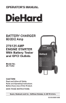
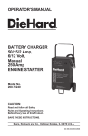
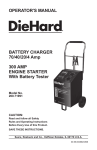
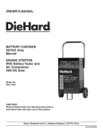
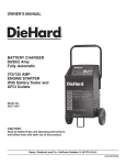
OPERATOR’S MANUAL
®
BATTERY CHARGER
40/20 Amp
Manual
200 Amp
ENGINE STARTER
Model No.
200.71230
CAUTION:
Read and follow all Safety
Rules and Operating Instructions
Before Every Use of this Product.
Save these instructions.
Sears, Roebuck and Co., Hoffman Estates, IL 60179 U.S.A.
00-99-000880/0808
Table of Contents
SECTION
Page
1. IMPORTANT SAFETY INSTRUCTIONS
1
2. personal precautions 2
3. preparing to charge 3
4. charger location
3
5. dc connection precautions
3
6. when battery is installed in vehicle 4
7. when battery is outside vehicle 5
8. battery charging - ac connections
6
9. parts
5
10. features
9
11. assembly instructions
9
12. operating instructions
12
13. calculating charge time
13
14. using the engine start feature
15
15. maintenance instructions
15
16. storage instructions
15
17. troubleshooting
16
IMPORTANT: read and save this safety and instruction manual.
1.
IMPORTANT SAFETY INSTRUCTIONS
1.1
SAVE THESE INSTRUCTIONS - The DieHard model 71230 Manual Battery Charger, offers a wide range of features to accommodate the needs
for home or light commercial use. This manual will show you how to use
your charger safely and effectively. Please read and follow these instructions and precautions carefully as this manual contains important safety
and operating instructions.
1.2
WARNING: This product contains chemicals known to the State of California to cause cancer and birth defects or other reproductive harm. Wash
hands after handling.
1.3
Do not expose charger to rain or snow.
1.4
Use of an attachment not recommended or sold by the battery charger
manufacturer may result in a risk of fire, electric shock or injury to persons.
1.5
To reduce the risk of damage to electric plug or cord, pull by the plug
rather than the cord when disconnecting the charger.
1.6
An extension cord should not be used unless absolutely necessary. Use of
an improper extension cord could result in a risk of fire and electric shock.
If an extension cord must be used, make sure:
• That the pins on the plug of the extension cord are the same number,
size and shape as those of the plug on the charger.
• That the extension cord is properly wired and in good electrical condition
and;
• That the wire size is large enough for the AC ampere rating of the charger
as specified in Table 8.3.
1.7
Do not operate the charger with a damaged cord or plug; take it to a qualified serviceman. (Call customer service at: 800-SEARS-64).
1.8
Do not operate the charger if it has received a sharp blow, been dropped
or otherwise damaged in any way; take it to a qualified serviceman. (Call
customer service at: 800-SEARS-64).
1.9
Do not disassemble the charger; take it to a qualified serviceman when
service or repair is required. Incorrect reassembly may result in a risk of
electric shock or fire. (Call customer service at: 800-SEARS-64).
1.10 To reduce the risk of electric shock, unplug the charger from the outlet
before attempting any maintenance or cleaning. Turning off the controls
will not reduce this risk.
•1•
WARNING – RISK OF EXPLOSIVE GASES.
WORKING IN THE VICINITY OF A LEAD-ACID BATTERY IS DANGEROUS. BATTERIES GENERATE EXPLOSIVE GASES DURING NORMAL BATTERY OPERATION. FOR THIS REASON, IT IS OF UTMOST
IMPORTANCE THAT YOU FOLLOW THE INSTRUCTIONS EACH TIME
YOU USE THE CHARGER.
TO REDUCE THE RISK OF BATTERY EXPLOSION, FOLLOW THESE
INSTRUCTIONS AND THOSE PUBLISHED BY THE BATTERY MANUFACTURER AND THE MANUFACTURER OF ANY EQUIPMENT YOU
INTEND TO USE IN THE VICINITY OF THE BATTERY. REVIEW THE
CAUTIONARY MARKINGS ON THESE PRODUCTS AND ON THE
ENGINE.
2.
PERSONAL PRECAUTIONS
2.1
Consider having someone close enough by to come to your aid when you
work near a lead-acid battery.
2.2
Have plenty of fresh water and soap nearby in case battery acid contacts
your skin, clothing or eyes.
2.3
Wear complete eye protection and clothing protection. Avoid touching your
eyes while working near the battery.
2.4
If battery acid contacts your skin or clothing, wash immediately with soap
and water. If acid enters your eye, immediately flood the eye with cold running water for at least 10 minutes and get medical attention immediately.
2.5
NEVER smoke or allow a spark or flame in the vicinity of a battery or
engine.
2.6
Be extra cautious to reduce the risk of dropping a metal tool onto the battery. It might spark or short-circuit the battery or other electrical part that
may cause an explosion.
2.7
Remove personal metal items such as rings, bracelets, necklaces and
watches when working with a lead-acid battery. A lead-acid battery can
produce a short-circuit current high enough to weld a ring or the like to
metal, causing a severe burn.
2.8
Use this charger for charging a LEAD-ACID battery only. It is not intended
to supply power to a low voltage electrical system other than in a startermotor application. Do not use this battery charger for charging dry-cell
batteries that are commonly used with home appliances. These batteries
may burst and cause injury to persons and damage to property.
2.9
NEVER charge a frozen battery.
2.10 WARNING: Pursuant to California Proposition 65, this product contains
chemicals known to the State of California to cause cancer and birth defects or other reproductive harm.
•2•
3.
PREPARING TO CHARGE
3.1
If it is necessary to remove the battery from the vehicle to charge it, always remove the grounded terminal from the battery first. Make sure all of
the accessories in the vehicle are off, so as not to cause an arc.
3.2
Be sure the area around the battery is well ventilated while the battery is
being charged.
3.3
Clean the battery terminals. Be careful to keep corrosion from coming into
contact with your eyes.
3.4
Add distilled water to each cell until the battery acid reaches the level
specified by the battery manufacturer. Do not overfill. For a battery without
removable cell caps, such as valve regulated lead-acid batteries, carefully
follow the manufacturer’s recharging instructions.
3.5
Study all of the battery manufacturer’s specific precautions while charging
and recommended rates of charge.
3.6
Determine the voltage of the battery by referring to the vehicle owner’s
manual and make sure that the output voltage selector switch is set to the
correct voltage. If the charger has an adjustable charge rate, charge the
battery at the lowest rate first.
4.
CHARGER LOCATION
4.1
Locate the charger as far away from the battery as the DC cables permit.
4.2
Never place the charger directly above the battery being charged; gases
from the battery will corrode and damage the charger.
4.3
Never allow battery acid to drip onto the charger when reading the electrolyte specific gravity or filling the battery.
4.4
Do not operate the charger in a closed-in area or restrict the ventilation in
any way.
4.5
Do not set a battery on top of the charger.
5.
DC CONNECTION PRECAUTIONS
5.1
Connect and disconnect the DC output clips only after setting all of the
charger switches to the “off” position and removing the AC plug from the
electrical outlet. Never allow the clips to touch each other.
5.2
Attach the clips to the battery and chassis, as indicated in steps 6.5, 6.6,
and 7.2 thru 7.4.
•3•
6.
FOLLOW THESE STEPS WHEN BATTERY IS INSTALLED IN
VEHICLE.
A SPARK NEAR THE BATTERY MAY CAUSE A BATTERY EXPLOSION. TO REDUCE THE RISK OF A SPARK NEAR THE BATTERY:
NEGATIVE GROUNDED SYSTEM
6.1
Position the AC and DC cables to reduce the risk of damage by the hood,
door, or moving engine parts.
6.2
Stay clear of fan blades, belts, pulleys and other parts that can cause
injury.
6.3
Check the polarity of the battery posts. The POSITIVE (POS, P, +) battery
post usually has a larger diameter than the NEGATIVE (NEG, N, -) post.
6.4
Determine which post of the battery is grounded (connected) to the chassis. If the negative post is grounded to the chassis (as in most vehicles),
see step 6.5. If the positive post is grounded to the chassis, see step 6.6.
6.5
For a negative-grounded vehicle, connect the POSITIVE (RED) clip from
the battery charger to the POSITIVE (POS, P, +) ungrounded post of the
battery. Connect the NEGATIVE (BLACK) clip to the vehicle chassis or
engine block away from the battery. Do not connect the clip to the carburetor, fuel lines or sheet-metal body parts. Connect to a heavy gauge metal
part of the frame or engine block.
6.6
For a positive-grounded vehicle, connect the NEGATIVE (BLACK) clip
from the battery charger to the NEGATIVE (NEG, N, -) ungrounded post
of the battery. Connect the POSITIVE (RED) clip to the vehicle chassis or
engine block away from the battery. Do not connect the clip to the carburetor, fuel lines or sheet-metal body parts. Connect to a heavy gauge metal
part of the frame or engine block.
6.7
When disconnecting the charger, turn all switches to off, disconnect the
AC cord, remove the clip from the vehicle chassis, and then remove the
clip from the battery terminal.
6.8
See OPERATING INSTRUCTIONS for length of charge information.
•4•
7.
FOLLOW THESE STEPS WHEN BATTERY IS OUTSIDE VEHICLE.
A SPARK NEAR THE BATTERY MAY CAUSE A BATTERY EXPLOSION. TO REDUCE THE RISK OF A SPARK NEAR THE BATTERY:
7.1
Check the polarity of the battery posts. The POSITIVE (POS, P, +) battery
post usually has a larger diameter than the NEGATIVE (NEG, N, -) post.
7.2
Attach at least a 24-inch-long 6-gauge (AWG) insulated battery cable to
the NEGATIVE (NEG, N, -) battery post.
7.3
Connect the POSITIVE (RED) charger clip to the POSITIVE (POS, P, +)
post of the battery.
7.4
Position yourself and the free end of the cable you previously attached to
the NEGATIVE (NEG, N, -) battery post as far away from the battery as
possible – then connect the NEGATIVE (BLACK) charger clip to the free
end of the cable.
7.5
Do not face the battery when making the final connection.
7.6
When disconnecting the charger, always do so in reverse sequence of
the connecting procedure and break the first connection while as far away
from the battery as practical.
7.7
A marine (boat) battery must be removed and charged on shore. To
charge it onboard requires equipment specially designed for marine use.
•5•
8.
8.1
battery charging - ac connections
For all grounded cord-connected battery chargers:
• GROUNDING AND AC POWER CORD CONNECTION INSTRUCTIONS
– The charger should be grounded to reduce the risk of electric shock.
The charger is equipped with an electric cord having an equipmentgrounding conductor and a grounding plug. The plug must be plugged
into an outlet that is properly installed and grounded in accordance with
all local codes and ordinances.
• DANGER – Never alter the AC cord or plug provided – if it will not fit
the outlet, have the proper outlet installed by a qualified electrician. An
improper connection can result in a risk of an electric shock.
8.2
For all grounded, cord-connected battery chargers with an input rating less
than 15-amperes and intended for use on a nominal 120-volt circuit:
• This battery charger is for use on a nominal 120-volt circuit, and has a
grounding plug that looks like the plug illustrated in sketch A in Figure 8.4.
A temporary adaptor, which looks like the adapter illustrated in sketches
B and C, may be used to connect this plug to a two-pole receptacle as
shown in sketch B if a properly grounded outlet is not available. The temporary adapter should be used only until a properly grounded outlet can
be installed by a qualified electrician.
• DANGER – Before using an adapter as illustrated, be certain that the
center screw of the outlet plate is grounded. The green-colored rigid
ear or lug extending from the adapter must be connected to a properly
grounded outlet – make certain it is grounded. If necessary, replace the
original outlet cover plate screw with a longer screw that will secure the
adapter ear or lug to the outlet cover plate and make a ground connection to the grounded outlet.
•6•
8.3
Recommended minimum AWG size for extension cords for battery
chargers:
AC input rating,
a
amperes
But less
At least
than
0
2
2
3
3
4
4
5
5
6
6
8
8
10
10
12
12
14
14
16
16
18
18
20
25
(7.6)
18
18
18
18
18
18
18
16
16
16
14
14
AWG size of cord
Length of cord, feet (m)
50
100
150
(15.2)
(30.5)
(45.6)
18
18
16
18
16
14
18
16
14
18
14
12
16
14
12
16
12
10
14
12
10
14
10
8
12
10
8
12
10
8
12
8
8
12
8
6
a
If the input rating of a charger is given in watts rather than in
amperes, the corresponding ampere rating is to be determined
by dividing the wattage rating by the voltage rating ± for
example:
1250 watts/125 volts = 10 amperes
8.4
Grounding Methods
•7•
9.
parts
The Sears service centers offer the following replacement parts for your
battery charger. If you are having trouble with your battery charger, please
contact a qualified service person to diagnose and/or repair your unit. It
is not recommended that the consumer service the internal components
of the battery charger, as improper handling or repair could lead to shock,
electrocution, damage to the charger, or result in fire. As such, please contact 1-800-SEARS-64 for troubleshooting assistance and 1-800-366-PART
for repair or replacement parts.
Replacement Parts List DieHard 71230:
Item
Description
Part Number
1
Handle
35-99-000286
2
Negative (BLK) Cable w/Clamps
38-99-000396
3
Positive (RED) Cable w/Clamps
38-99-000410
4
Power Cord
90-026-096
5
Circuit Breaker Assembly
39-99-000099
6
Rectifier Assembly
22-99-001081
7
Transformer
93-026-532
8
Fan Motor
00-99-000063
10
Wheel
00-99-000080
11
Hub Cap
52-00-000008
12
Axle
00-99-000060
13
Axle Mtg. Brackets
11-99-004366
14
Mounting Foot
11-99-003352
15
Rotary Switch 3 Position
04-99-000052
16
Ammeter
53-99-100088
17
Rocker Switch 2 Position
04-99-000050
•8•
10. features
1
2
3
1. Output Selector Switches
2. Ameter
3. Clamps
4. Wheels
4
11.
Assembly instructions
It is important to fully assemble your charger before use. Follow these
instructions for assembly:
PARTS
TOOLS NEEDED
Two, 10-32, thread cutting screws
Four, 1/4-20, thread cutting scews
Two wheels
One axle
Two axle caps
Two axle brackets
One handle
One mounting foot
3/8” wrench (for mounting foot)
5/16” wrench (for wheels)
Hammer
Phillips screwdriver
•9•
11.1 To attach the axle assembly:
Remove charger from packing materials and place upside down on a flat
surface. Attach mounting foot and secure with the four, 1/4-20 thread cutting screws.
11.2 Hold axle upright on floor or work surface. Then, using a hammer, tap one
of the plastic axle caps onto the top end of the axle. Be sure to tap the
axle cap on straight. Slide both wheels onto the axle with the recessed
hubs facing out as shown. Install the second axle cap.
• 10 •
11.3 Place the charger on its side. Place one end of each bracket into slot, then
place the axle assembly under each bracket. Fasten the other side of the
brackets using the two, 10-32 screws provided.
11.4 To Attach Handle:
Turn the charger right side up onto its foot and wheels. Remove the two
top screws from each side of the charger. Align the handle so the screw
holes are aligned with the screw holes on each side of the wheel charger.
Attach the handle using the same screws.
• 11 •
12. operating instructions
200A 12V
ENGINE
START
2A 12V
CHARGE
OFF
40A 12V
CHARGE
SELECT
VOLT/AMP SELECTOR
12.1 SETTING THE CONTROLS
All controls for your charger are located on the front of the unit. Follow
these instructions to obtain the accurate charge level for your battery.
12.2 Output Selector Switches:
Two switches are used to select the rate of charge or function; a 3-position switch on the right, and a 2-position switch to the left of it. Use the
3-position switch to select:
• 2 Amp Trickle Charge: Use for charging small batteries and warming
large batteries. The lower the charge rate, the longer it will take, but the
battery is subjected to much less stress.
• OFF: Leave the switch in the OFF Position while connecting the charger
to the battery and to the AC power outlet.
• Select: This setting enables you to select one of the two settings offered
by the 2-position switch.
• Use the 40 Amp Charge rate for a fast charge.
• Use the 200 Amp Engine Start for cranking the engine. Remember that
little or no charging has been done by the charger and your battery will
still need further charging by the vehicle charging system once the engine
starts.
12.3 Ammeter: Indicates the amount of current measured in amperes that is
being drawn by the battery. For example, in the 40 amp charge rate, a
typical discharged battery will initially draw approximately 40 amps. As
the battery continues to charge, current will taper to 15 to 20 amps at full
charge. The Start area of the meter indicates a high rate of current being drawn from the charger. When cranking an engine, the starter motor
draws upwards to 200-300 amps. The meter needle will be at the extreme
right side of the start area. Sometimes, for the first few minutes of its
charge, the battery will draw more than 40 amps; in this case, the needle
may be within, but not all the way over, to the right side of the start area.
• 12 •
The 2 amp charge rate may not indicate activity on the meter. The meter
does not have the resolution to display this low rate.
13. calculating charge time
13.1 The Chart Method
Use the following table to more accurately determine the time it will take to
bring a battery to full charge. First, identify where your battery fits into the
chart.
• Small batteries — motorcycles, garden tractors, etc. — are usually rated
in Ampere Hours (AH). For example: 6 to 12 AH, or 12 to 32 AH.
• Batteries in cars and smaller trucks are usually rated in Reserve Capacity
(RC), Cold-Cranking Amps (CCA), or both.
• Marine or deep-cycle batteries are usually rated in Reserve Capacity
(RC).
•NR
means that the charger setting is NOT RECOMMENDED.
Find your battery’s rating on the chart below and note the charge time
given for each charger setting. The times given are for batteries with a
50-percent charge rate prior to recharging. Add more time for severely
discharged batteries. Time is given in hours unless otherwise specified.
CHARGE RATE/
CHARGING TIME - HOURS
BATTERY SIZE/RATING
SMALL
BATTERIES
CAR/TRUCKS
2 AMP
40 AMP
6 - 12 AH
2-4
NR
12 - 32 AH
4 - 10
NR
200 - 315 CCA
40 - 60 RC
11 - 14
30 to 45 min.
315 - 550 CCA
60 - 85 RC
14 - 18
45 min - 1
hour
550 - 1000 CCA
85 - 190 RC
18 - 35
1 - 2 hours
80 RC
18
NR
140 RC
27
NR
160 RC
30
NR
180 RC
33
NR
Motorcycle, garden, tractor, etc.
MARINE/DEEP CYCLE
• 13 •
13.2 The Hydrometer or Electronic Method
To find the time needed to fully charge your battery, determine the battery’s charge level with a hydrometer or electronic Percent-of-Charge
Tester. The following table will help you convert hydrometer readings to
percent of charge values.
SPECIFIC GRAVITY
OF CHARGE
PERCENT OF CHARGE PERCENT
NEEDED
1.265
100%
0%
1.225
75%
25%
1.155
25%
75%
1.120
0%
100%
When you know the percent of charge and the Amp Hour (AH) rating of
your battery, you can calculate the approximate time needed to bring your
battery to a full charge.
To convert Reserve Capacity to Amp Hours, divide Reserve Capacity by
2, and add 16:
Amp Hours = Reserve Capacity + 16
2
NOTE: The Reserve Capacity can be obtained from the battery specification sheet or the owner’s manual.
To calculate time needed for a charge:
• Find the percent of charge needed. (A battery at 50 percent charge that
will be charged to 100 percent needs another 50 percent (.50)).
• Multiply the Amp Hour rating by the charge needed (.50) and divide by
the charger setting (2 or 10 amps).
• Multiply the result by 1.25 and you’ll have the approximate time needed,
in hours, to bring the battery to full charge.
• Add one additional hour for a deep-cycle battery.
Example:
Amp Hour Rating x charge needed Charger Setting
x
100 (AH Rating) x .50 (charge needed) x
50 (Charger Setting)
1.25 =
1.25 =
hours of
charge
1.25
hours
100 x .50 = 1 x 1.25 = 1.25
50
You will need to charge your 100-Ampere Hour Battery for approximately
1 1/4 hours at the 50-Amp charge rate using the above example.
• 14 •
14. using the engine start feature
Your battery charger can be used to jump-start your car if the battery is
low. Follow these instructions on how to use the engine start feature.
14.1 Set the right-hand OUTPUT SELECTOR switch to the OFF position. Then
follow the instructions for connecting the charger to the battery in the Operating Instructions section.
14.2 Once the charger is connected, set the right-hand selector switch to SELECT and set the left selector switch to the 200 AMP START position.
14.3 Plug the power cord into a grounded AC wall outlet.
14.4 Crank the engine for no more than five seconds. If the engine does not
start, wait four minutes before cranking again.
14.5 During extremely cold weather, or if the battery is severely exhausted,
charge the battery for about five minutes before cranking the engine.
14.6 If the engine still does not start, charge the battery for five more minutes in
the 40 amp position before cranking it again for five seconds.
14.7 After the engine starts, unplug the charger power cord from the outlet.
Then move the right-hand SELECTOR SWITCH to the OFF position before disconnecting the battery leads.
IMPORTANT: Do not try to start the engine without a battery in it. You
could cause damage to the electrical system.
If the engine does turn over, but never starts up, there is not a problem
with the starting system, there is a problem somewhere else with the
vehicle. STOP cranking the engine until the other problem has been diagnosed and corrected.
15. maintenance instructions
15.1 Before performing maintenance, unplug and disconnect battery charger
(see sections 6.7 or 7.6).
15.2 After use, use a dry cloth to wipe all battery corrosion and other dirt or oil
from terminals, cords, and the charger case.
15.3 Through routine maintenance, ensure all user installed parts are secured.
15.4 Servicing does not require opening the unit. There are no user-serviceable
parts.
16. storage instructions
16.1 Store charger unplugged, in an upright condition. Cord will still conduct
electricity until it is unplugged from outlet.
16.2 Store inside, in a dry, cool place (unless you’re using an on-board Marine
Charger ).
16.3 Do not store clips on handle, clipped together, on or around metal, or
clipped to cables.
• 15 •
17.
troubleshooting
PROBLEM
POSSIBLE CAUSE
SOLUTION/REASONS
No reading on the ammeter.
Clamps are not making a
good connection.
Check for poor connections to battery and frame.
Make sure connecting
points are clean. Rock
clips back and forth for a
better connection.
2-amp charge rate is being used.
Ammeter may show no
activity at the 2-amp
charge rate.
No reading on ammeter.
Fan inside wheel charger
appears to not be working.
No power at receptacle.
Check for open fuse or
circuit breaker supplying
AC outlet.
AC cord and/or extension
cord is loose.
Check power cord and
extension cord for loose
fitting plug.
Circuit breaker in charger
cycles on and off with a
clicking sound.
Shorted battery clamps.
Circuit breaker cycles
when current draw is
too high. Separate the
clamps. Check for worn
cables and replace if
needed.
Shorted battery.
Have a Sears technician
test the battery.
Charger leads reversed.
Correct Connections.
Volt/Amp Selector Switch
set to the START position.
Correct Volt/Amp Selector
setting.
Drawing more than 250
amps for a period of 3
seconds or less.
Crank time varies with the
amount of current drawn.
If cranking draws more
than 250 amps, crank
time may be less than 3
seconds.
Failure to wait for 4
minutes (240 seconds)
between cranks.
Wait 4 minutes before
next crank.
The charger may be
heated up.
The thermal protector may
have tripped and needs a
little longer to close. Make
sure that the charger
vents are not blocked.
Wait and try again.
Battery may be severely
discharged.
On a severely discharged
battery, charge for 10 to
15 minutes in the 20 amp
manual rate to help assist
in cranking.
Short start cycle when
cranking engine.
• 16 •
PROBLEM
POSSIBLE CAUSE
Ammeter reads less than
Extension cord too long or
selected charge rate when wire gauge too small.
charging a discharged
battery.
Weak cell or sulfated plate
in battery.
Charger makes a loud
buzz or hum.
Ammeter reading stays
high.
SOLUTION/REASONS
Use shorter or heavier
gauge extension cord.
Sulfated battery will
eventually take a normal
charge if left connected. If
the battery will not take a
charge, have it tested by a
Sears technician.
Battery is only partially
discharged.
Continue charging battery.
Transformer laminations
vibrate (buzz).
Continue charging. Buzz
is not abnormal.
Shorted diode (hum).
Have charger tested by
Sears technician.
Battery is severely discharged.
Continue charging battery
for two more hours. If
problem continues, have
the battery checked by a
Sears or other qualified
service dealer.
• 17 •
• 18 •