1
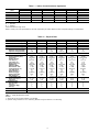
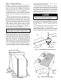
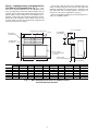
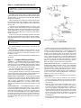
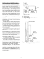
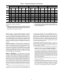
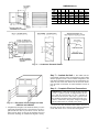
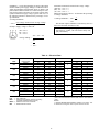
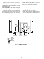
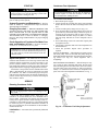
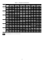
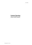
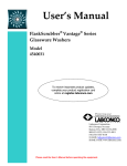
09BY006-024
Remote Air-Cooled Condenser Units
5 to 20 Tons
Installation, Start-Up and
Service Instructions
CONTENTS
Page
SAFETY CONSIDERATIONS . . . . . . . . . . . . . . . . . . . 1
GENERAL . . . . . . . . . . . . . . . . . . . . . . . . . . . . . . . . . . . 1
INSTALLATION . . . . . . . . . . . . . . . . . . . . . . . . . . . . . 1-14
Step 1 — Complete Pre-Installation Checks . . . 1
Step 2 — Rig and Place Unit . . . . . . . . . . . . . . . . . 7
• RIGGING
• PLACING THE UNIT
• VIBRATION ISOLATION
• POSITIONING THE 09BY UNIT
• VERTICAL DISCHARGE
Step 3 — Install Accessory Low-Ambient
Kit or Inlet Filter Kit (If Required) . . . . . . . . . . . 8
Step 4 — Install Rain Drain . . . . . . . . . . . . . . . . . . 9
Step 5 — Complete Refrigerant Piping . . . . . . . 9
• GENERAL
• REFRIGERANT LINE SIZING
• PRESSURE RELIEF
• REFRIGERANT RECEIVER
• COIL CONNECTIONS
• LIQUID LIFT
• SWEAT CONNECTIONS
• FIELD PIPING
• MANIFOLDING CIRCUITS
• CHECK VALVE
• SERVICE VALVES
Step 6 — Ductwork . . . . . . . . . . . . . . . . . . . . . . . . . 11
• CONDENSER AIR DUCT INSULATION
Step 7 — Insulate the Unit . . . . . . . . . . . . . . . . . . 12
Step 8 — Complete Electrical Connections . . 12
• GENERAL
• MAIN POWER WIRING
• CONTROL CIRCUIT POWER WIRING
• GENERAL WIRING NOTES
START-UP . . . . . . . . . . . . . . . . . . . . . . . . . . . . . . . . . . 15
System Evacuation and Dehydration . . . . . . . . . 15
Charging Procedure . . . . . . . . . . . . . . . . . . . . . . . . . 15
Check Operation of Condenser Fan Motor
Controls and Rotation of Fans . . . . . . . . . . . . . 15
Adjust Fan Speed . . . . . . . . . . . . . . . . . . . . . . . . . . . 15
SERVICE . . . . . . . . . . . . . . . . . . . . . . . . . . . . . . . . . . 15-17
Cleaning Condenser Coils . . . . . . . . . . . . . . . . . . . 15
Lubrication . . . . . . . . . . . . . . . . . . . . . . . . . . . . . . . . . 15
Condenser Fan Adjustment . . . . . . . . . . . . . . . . . . 15
• TO CHANGE FAN SPEED
• PULLEY ALIGNMENT
• BELT TENSION ADJUSTMENT
• TO CHANGE FAN WHEEL
• TO REPLACE FAN BEARING
MAINTENANCE . . . . . . . . . . . . . . . . . . . . . . . . . . . . . 17
Cleaning . . . . . . . . . . . . . . . . . . . . . . . . . . . . . . . . . . . . 17
Inspection . . . . . . . . . . . . . . . . . . . . . . . . . . . . . . . . . . 17
Air Filters . . . . . . . . . . . . . . . . . . . . . . . . . . . . . . . . . . . 17
Page
Condensate Drain . . . . . . . . . . . . . . . . . . . . . . . . . . . 17
TROUBLESHOOTING . . . . . . . . . . . . . . . . . . . . . . . . 17
START-UP CHECKLIST . . . . . . . . . . . . . . . . CL-1,CL-2
SAFETY CONSIDERATIONS
Installing, starting up, and servicing air-conditioning equipment can be hazardous due to system pressures, electrical
components, and equipment location.
Only trained, qualified installers and service mechanics
should install, start-up, and service this 09BY equipment
(Fig. 1).
When working on the equipment, observe precautions in
the literature and on tags, stickers, and labels attached to the
equipment.
Follow all safety codes. Wear safety glasses and work gloves.
Keep quenching cloth and fire extinguisher nearby when brazing. Use care in handling, rigging, and setting bulky
equipment.
ELECTRIC SHOCK HAZARD
Separate power sources (main and control
power circuits) are used for these units. Be
sure both main and control power circuits are
disconnected before servicing.
GENERAL
The 09BY air-cooled condenser is a remote air-cooled condenser designed to be used with the 50BZ vertical packaged
units. See Table 1. Airflow is horizontal, both into and out
from the same face of the unit. The unit is designed to be
mounted indoors in a window, through the wall in high-rise
buildings, or on the wall on the building exterior. See Fig. 2
for typical applications. Ductwork is not needed, but may be
added easily if required by the application. Airflow is provided by centrifugal fans with an adjustable belt drive to meet
varying static requirements. Units may also be matched with
other compressor and evaporator combinations. Contact your
local representative for more details.
Check space requirements, service clearances, floor strength,
location of piping, size of power supply, and location of ductwork (if used) before installing. See Fig. 3 for unit dimensions and Table 2 for unit operating weights.
INSTALLATION
Step 1 — Complete Pre-Installation Checks —
Examine unit for damage incurred during shipment. File claim
immediately with transit company if damage is found. Check
the shipment for completeness. Verify that the nameplate electrical requirements match the available power supply.
Manufacturer reserves the right to discontinue, or change at any time, specifications or designs without notice and without incurring obligations.
Book 2 4
PC 111
Catalog No. 530-912
Printed in U.S.A.
Form 09BY-3SI
Pg 1
4-99
Replaces: 09BY-2SI
Tab 4a 4a
RIGHT SIDE VIEW
VIEW A-A
006-014 UNIT SIZE
REAR VIEW (HORIZONTAL DISCHARGE)
VIEW A-A
008-014 UNIT SIZE
Fig. 1 — 09BY Units
2
LEFT SIDE VIEW
VIEW B-B
016-024 UNIT SIZE
HANGER
RODS
TO OUTSIDE
DISCHARGE
DUCT
09BY
INLET
DUCT
TO RAIN DRAIN
(REQUIRED IF RAIN
WILL ENTER UNIT)
INSULATE IF THROUGH
CONDITIONED SPACE
TO REFRIGERANT
PIPING COMPRESSOR/
EVAPORATOR UNIT
09BY IN REMOTE APPLICATION WITH DUCTWORK
(Shown Suspended from Ceiling)
OUTSIDE
WALL
OUT
50BZ
WALL
LOUVERS
(FIELD
SUPPLIED)
09BY
IN
POWER
CONNECTION
FLOOR
STAND*
LEGEND
Refrigerant Connection
TO RAIN
DRAIN
(REQUIRED
IF RAIN WILL
ENTER UNIT)
HEIGHT AS
REQUIRED
FOR WINDOW
OR WALL
OPENING
09BY DIRECT CONNECTION TO 50BZ UNIT
Field-Supplied Refrigerant Piping
*Field-Supplied Floor Stand (Height to Match Wall Opening).
Fig. 2 — Mounting Applications
3
09BY DIMENSIONS (English)
DIMENSION
A
B
C
D
E
F
G
H
J
K
L
M
N
006
(Ft-in.)
2-111⁄2
1- 711⁄16
4- 07⁄16
1-111⁄4
0-111⁄8
0- 63⁄16
1- 15⁄16
0- 95⁄16
0- 3
3- 51⁄8
1-105⁄8
0- 19⁄16
0- 91⁄6
008
(Ft-in.)
3- 613⁄16
1-115⁄8
4- 8
2- 39⁄16
1- 2
0- 57⁄8
1- 35⁄8
0-11
0- 3
4- 01⁄4
2- 3
0- 19⁄16
0- 7
012
(Ft-in.)
3- 613⁄16
1-115⁄8
5- 31⁄2
2- 39⁄16
1- 2
0- 711⁄16
1- 47⁄8
0-11
0- 2
4- 97⁄8
2- 3
0- 19⁄16
0- 7
014
(Ft-in.)
3- 613⁄16
1-115⁄8
5-11
2- 39⁄16
1- 2
0-117⁄16
1- 47⁄8
0-11
0- 2
5- 51⁄4
2- 3
0- 19⁄16
0- 7
09BY DIMENSIONS (SI)
016,024
(Ft-in.)
5- 0
2- 97⁄16
7- 69⁄16
3- 13⁄4
1- 73⁄4
1-1111⁄16
2- 0
1- 31⁄2
0- 27⁄16
7- 01⁄4
2- 9
0- 31⁄8
0- 97⁄8
DIMENSION
A
B
C
D
E
F
G
H
J
K
L
M
N
Fig. 3 — Base Unit Dimensions
4
006
(mm)
902
500
1231
590
282
156
338
236
76
1044
575
40
141
008
(mm)
1087
600
1422
701
357
150
396
280
76
1226
686
40
178
012
(mm)
1087
600
1613
701
357
195
428
318
51
1463
686
40
178
014
(mm)
1087
600
1804
701
357
290
428
318
51
1657
686
40
178
016,024
(mm)
1526
850
2300
941
502
347
610
394
63
2140
838
80
251
UNIT
09BY
TOTAL
006
008
012
014
016
024
267
357
441
471
837
970
CORNER WEIGHT
(lb)
A
B
C
D
46
31
76 113
59
41
105 152
73.5 49.5 128 190
79
52
134 205
141
96
242 358
164
111
280 415
CENTER OF GRAVITY
(in.)
AA
AB
AC
29
6
14
33
7
17
38
7
17
43
7
17
54
10
24
54
10
24
Refrigerant coil connections at the control box end.
3⁄89 [10 mm] liquid, 5⁄89 [16 mm] suction ODS.
AIRFLOW
CORNER
C
36" MIN.
REQUIRED
SEE NOTE 2
0"
REQUIRED
ALLOW ACCESS
TO CLEAN
CONDENSER
COIL
CORNER
D
TOP
36"
RECOMMENDED
09BY
BELT ACCESS
CORNER
B
ELECTRICAL
ACCESS
FRONT
36"
ALTERNATE BELT
ACCESS
CORNER
A
0" REQUIRED (IF
BELT ACCESS AND
SHAFT REMOVAL
ACCESS
ARE PROVIDED
ON SIDE
0" (IF REAR ACCESS
IS TO BE USED
TO SERVICE BELTS)
Service Clearance
Operational clearances are 09 on all sides and top.
NOTES:
1. Operational clearances are 0 in. on all sides of the unit.
2. Service clearances are 0 in. (minimum) on the top, rear, and front
of the unit. A minimum of 3 ft service clearance is required on the
unit right side, and a 3 ft clearance is recommended on the left
side (2 ft is the minimum). One side of the unit (either right, left, or
rear) should have the following minimum clearance for removal of
the blower shaft:
UNIT
SIZE
006
008
012
014
016
024
APPROX. SHAFT LENGTH
(in.)
41.0
47.0
51.0
51.0
55.5
73.0
Fig. 3 — Base Unit Dimensions (cont)
5
Table 1 — Indoor Circuit/Condenser Application
UNIT
50BZ
006
008
012
014
016
09BY
006
S
008
O
S
012
014
O*
S
O
S
016
024
O
S
O
LEGEND
S — Standard
O — Optional
*Field manifolded for single circuit.
NOTE: Contact your local representative for use with reciprocating air-cooled chillers and other compressor-bearing unit combinations.
Table 2 — Physical Data
UNIT 09BY
NOMINAL CAPACITY (tons)
OPERATING WEIGHT (lb)
REFRIGERANT
NUMBER OF CIRCUITS
STORAGE VOLUME (ft3/ckt)
Minimum Charge (Lb/Ckt)
Optimum Charge (Lb/Ckt)
HOLDING CHARGE
CONDENSER FAN
Nominal Airflow (Cfm)
Cfm Range
Number of Fans
Fan Size (in.)
Fan Pulley (in.)
Motor Pulley (in.)
RPM Range
Maximum RPM
Belt Number...Size
Center Distance (in.)
Fan Shaft (mm)
Motor Shaft (in.)
Motor Hp (Type)
Motor Frame Size
Max. Motor Hp
CONDENSER COIL
Rows...Fins per in.
Face Area
CONNECTIONS
Hot Gas (Qty)
Size (in.)
Liquid Line (Qty)
Size (in.)
CONDENSATE DRAIN (in.)
CONTROLS
006
5
267
008
71⁄2
357
1
1.8
6
8.38
1
2.7
11
14.5
3000
2000-4000
2
8.8 x 8.8
5.7
2.6-5.5
1058-1450
1705
1...A43
11.2/12.6
20
7⁄8
2 (TEFC)
145T
3
4500
3000-6000
2
11 x 11
7.6
4.2-5.5
960-1260
1365
1...B46
13.6/15.0
25
11⁄8
3 (TEFC)
182T
5
4...14
6.33
5...14
8.75
1
⁄
1
1⁄2
12
1
⁄
1
1⁄2
12
012
10
441
014
12
471
R-22
2
2
1.8
1.8/2.7
6
6/11
8.38
8.38/14.5
Nitrogen Holding Charge
Centrifugal
6000
6800
4000-8000
5000-8000
2
2
11 x 11
11 x 11
8.6
6.7
4.2-5.5
4-5
850-1110
1045-1306
1365
1365
1...B48
2...A45
13.6/15.0
13.6/15.0
25
25
1
1 ⁄8
11⁄8
5 (TEFC)
5 (TEFC)
182T
184T
5
5
Copper Tube, Aluminum Fin
5...15
5...14
10.49
10.80
016
15
837
024
20
970
2
2.7
11
14.5
2
2.7
11
14.5
7500
6000-12,000
2
12.4 x 12.4
9.6
4.7-6
875-1095
1210
2...B88
32.6/33.6
25
11⁄8
5 (TEFC)
184T
71⁄2
10,000
8,000-16,000
2
14 x 14
11.6
4.7-6
725-905
955
2...B88
30.0/30.7
30
11⁄8
7.5 (TEFC)
213T
71⁄2
4...14
19.38
5...14
19.38
2
2
2
1⁄2
1 ⁄2
⁄
2
2
2
1⁄2
1⁄2
1 ⁄2
3⁄4 Female Pipe Thread
24 Volt Control Fan Contactor Provided In Unit
12
LEGEND
TEFC — Totally Enclosed Fan Cooled
NOTES:
1. Same unit may be mounted vertically or horizontally.
2. Optimum charge is based on 15° F subcooling. Minimum charge is based on 5° F subcooling.
6
2
⁄
2
1⁄2
12
POSITIONING THE 09BY UNIT — Refer to notes in
Fig. 3 for typical service clearances.
To suspend the unit, use 4, field-supplied, 1⁄2-in. diameter
(or larger) threaded rods. Mount 2 heavy channels under the
entire width of the unit, allowing them to protrude beyond
the width of the unit so that supporting rods can be installed
on the channel ends. Attach minimum 1⁄2-in. threaded supporting rods (field-supplied) to channels through a rubber or
spring isolator. See. Fig. 5.
Step 2 — Rig and Place Unit
RIGGING — The 09BY units are mounted on skids. Leave
the unit on the skid until it is in the final position. While on
the skid, the unit can be rolled, dragged or forklifted; do not
apply force to the unit. Use a minimum of 3 rollers when
rolling, and raise from above to remove the skid when unit
is in the final position. See Fig. 4 for rigging details.
PLACING THE UNIT — Locate the condenser where an
adequate supply of outdoor air is available for the unit inlet.
NOTE: Unit inlet and discharge may both be ducted to the
outside.
Either provide inlet filters to protect the condenser coils,
or locate the condenser in an area free from airborne dirt or
other foreign material which could clog the coils. For multiple units, allow service clearance (Fig. 3) between units,
and locate unit discharges and inlets so that recirculation of
condenser air is prevented. Placement area must be level and
strong enough to support operating weight of the unit
(Table 2). Bolt unit securely in place when unit is positioned
and leveled. Fasteners for mounting unit are field supplied.
NOTE: It will be necessary to drill holes in the unit base or
side wall where bolts are to be mounted.
DO NOT use rods smaller than 1⁄2-in. diameter. Smaller
rods may not be strong enough to support the unit. Rods
must be securely anchored in ceiling joists.
Use a double hex nut when attaching hanger rods to brackets. A single nut could loosen from vibration of the unit. Pitch
unit approximately 1⁄4-in. toward drain in both directions (lengthwise and widthwise) to aid in condensate and/or rain
removal.
Before sliding unit into final position, check for clearance
to access panels and service area to install piping.
VERTICAL DISCHARGE — The 09BY units can be mounted
on a field-supplied stand as shown in Fig. 6 for vertical discharge. Also, provide a rain drain on the back of the unit.
IMPORTANT: Use care if rain will enter the unit (if
unit is located fully or partially outdoors). DO NOT
drill through the unit drain pan or leaks will result.
VIBRATION ISOLATION — Units mounted in or above
occupied spaces should employ some type of vibration isolation. For units that are floor mounted, rubber pads may be
located under each unit corner or unit may be mounted on
rubber shear isolators or on spring isolators. Unit may be
supported by its 4 corners, or a field-supplied support rail
may be used for each side. Size isolators with the corner
weights shown in Fig. 3. Units may also be suspended from
above. See Positioning the 09BY Unit section following and
Fig. 5 for recommended support and isolator mounting.
Ductwork attached to the condenser should be isolated from
the unit with a flexible collar on the inlet and outlet ducts.
1/2" THREADED
ROD*
09BY
UNIT
PROTRUDING
CHANNEL END*
RUBBER
ISOLATOR*
WASHER*
BRACKET*
*Field supplied.
DOUBLE HEX NUT*
FIELD SUPPLIED
Fig. 5 — Threaded Rod Installed in Bracket
SPREADER BAR
SUPPORTS
UNDER SKID
Fig. 6 — 09BY Vertical Discharge
Fig. 4 — Unit Rigging
7
An accessory filter rack may also be installed on the condenser air inlet to help keep the coil clean. This filter rack
should be installed before the ductwork is attached to the
unit, and before unit is mounted against a wall louver (if
required in your specific application). See Fig. 7.
Refer to installation instructions provided with the accessories for installation details.
Step 3 — Install Accessory Low-Ambient Kit or
Inlet Filter Kit (If Required) (See Fig. 7) — If the
unit will be operated with inlet air to the condenser below
50 F, a head pressure control low-ambient damper may be
required. The low-ambient kit controls head pressure by discharge dampers on the condenser fan. The dampers are actuated by a refrigerant-operated piston connected to the discharge line of the condenser. If low-ambient accessory will
be used, install it at this time (before final refrigerant and
ductwork connections are made).
0'-11 1/2" [292MM]
DIVIDER ON 014/016/024 ONLY
INSULATED
CONTROL BOX
LOW AMBIENT
ACCESSORY
FLANGE
B
1 1/16"
[27MM]
C
A
ACCESS DOOR
(ON FRONT)
E
DUCT FLANGE
1" TOP AND BOTTOM
3/4" SIDES
INLET FILTER
RACK ACCESSORY
F
DIM
A
B
C
D
E
F
D
006
mm
287
1068
151
1082
535
79
0'-3 1/8" [79MM]
008
ft.-in.
08-115⁄169
38-71⁄169
08-515⁄169
38-65⁄89
18-91⁄169
08-31⁄89
mm
366
1301
189
1264
643
152
012
ft.-in.
18-23⁄89
48-31⁄49
08-77⁄169
48-13⁄49
28-15⁄169
08-69
mm
366
1446
232
1451
643
79
ft.-in.
18-23⁄89
48-815⁄169
08-91⁄89
48-91⁄89
28-15⁄169
08-31⁄89
014
mm
366
1541
286
1645
643
79
ft.-in.
18-23⁄89
58-011⁄169
08-111⁄49
58-43⁄49
28-15⁄169
08-31⁄89
Fig. 7 — Base Unit Dimensions with Low Ambient Control
and Filter Rack Accessories
8
mm
560
2014
286
2211
845
65
016,024
ft.-in.
18-101⁄169
68-65⁄169
08-111⁄49
78-31⁄169
28-91⁄49
08-29⁄169
Step 4 — Install Rain Drain (See Fig. 8)
IMPORTANT: A rain drain connection MUST BE
USED if any possibility exists of rain water entering
the unit.
The 09BY unit provides a choice of 2 drain locations. Rain
drain connection can be made on either side of the unit. Block
whichever drain is not being used, but DO NOT BLOCK
BOTH drain locations.
When connecting rain drains and condensate drains from
the unit to floor drains, sinks, or hoppers, connect drains downstream of trap to ensure that condensate does not drain back
into the unit.
A drain kit is provided (shipped in the fan section). This
kit consists of PVC drain fittings to adapt to field-supplied
threaded pipe. Make connections through the unit side panel.
Some applications may require connection to either galvanized steel or copper drain pipe; consult local code requirements for details.
If unit is located inside the building, the drain connection
near the refrigerant piping can be used for external drainage.
Run drain connection to a trapped drain, and plug unused
connection.
NOTE: Dimensions in [
IMPORTANT: NEVER use pipe smaller than 3⁄4 in.
in the drain run.
] are in millimeters.
Fig. 8 — Rain Drains
For vertical discharge units, provide a rain drain on the
back of the unit.
Pitch drain pipe downward at a slope of at least 1⁄4-in. per
ft for proper drainage. Provide tees plugged on one side for
cleanouts. Leave clearance for servicing, and observe all local sanitary codes.
Refer to Carrier System Design Manual for additional piping details.
If desired, the pressure relief requirement can also be satisfied by installing a fusible plug in the liquid line. To do so,
install a tee in the liquid line with a 1⁄4-in. NPT fitting on the
tee side, and install a fusible plug (part no. EK02KK105 or
similar). The temperature rating of the fusible plug should
be between 205 F and 220 F (96 C and 104 C). If a service
valve is used on the liquid line, be sure that both the piping
system and the condenser are protected for relief if all service valves are closed. Note that if the condenser is located
indoors, requirements for venting the fusible plug to the outdoors may apply. Consult local code requirements.
REFRIGERANT RECEIVER — A refrigerant receiver is not
furnished with 09BY condensers and is not recommended
for normal applications as its use is detrimental to adequate
refrigerant storage volume and desired effects of subcooling. However, if a particular application requires a receiver
to increase refrigerant holding capacity of the condenser, a
receiver can be used. Carrier recommends the following installation in such a case. See Fig. 9.
NOTE: When a receiver is to be used all year it should be
installed indoors.
• Locate the receiver below the condenser. The condenser
to receiver liquid line must be sized to allow free drainage. This line should be sized so the velocity does not exceed 100 fpm.
• Generous sizing of the liquid (condensate) line is especially important if the receiver is exposed at any time to
a warmer entering-air temperature than the condenser. It
must be large enough for the liquid to flow to the receiver
and at the same time allow flow of refrigerant vapor in the
opposite direction back to the condenser. The receiver will
become vapor locked under these conditions if re-evaporated
gas is not allowed to flow back to the condenser for
recondensation.
• Locate valves on each side of the receiver so receiver will
be isolated from system for normal operation.
Step 5 — Complete Refrigerant Piping
GENERAL — All field leak and pressure testing should be
done in accordance with local code requirements. If a local
code does not exist, use ASHRAE (American Society of Heating, Refrigeration and Air Conditioning Engineers) Standard 15, Safety Code for Mechanical Refrigeration.
For leak testing procedures, refer to the Carrier ‘‘Refrigerant Service Techniques’’ book, Form SFT-01.
For any parts that need to be removed, use a mini tubing
cutter. Perform phos-copper brazing on all field-made connections while protecting adjacent joints from heat.
REFRIGERANT LINE SIZING — Sizing depends on length
of lines between various sections of the refrigerant system.
Consider the amount of liquid lift and drop in the system as
well as proper compressor oil return. Consult Carrier
System Design Manual, Part 3, or Carrier E20-IIt Refrigerant Piping Computer Program for proper piping sizes and
design.
PRESSURE RELIEF — The ASHRAE Standard 15, Safety
Code for Mechanical Refrigeration states: ‘‘Every refrigerating system shall be protected by a pressure relief device or
some other means designed to safely relieve pressure due to
fire or other abnormal conditions.’’ Since 09BY condensers
do not have pressure relief devices, one must be field supplied and installed either before the liquid line service valve
or inside the 09BY unit. Each circuit must have its own pressure relief.
9
Procedure for Using the Refrigerant Receiver (Fig. 9)
During Normal Operation — Valve A is open and valves B
and C are closed. Receiver is isolated from the system.
For Servicing — Valves A and C are closed and valve B is
open. Run unit until all the refrigerant is in the receiver and
then close valve B. Unit is now ready for servicing.
To Resume Operation — Leave valve A closed and open valves
B and C. Run unit until the stored refrigerant is drawn into
the system. To completely remove the refrigerant from the
receiver, throttle valve B while noting condition of refrigerant in the liquid line sight glass; also monitor suction pressures. A sudden surge of bubbles in the sight glass and a
rapid decrease in suction pressure indicates that all the refrigerant has been withdrawn from the receiver. Immediately close valves B and C, and then open valve A. The unit
should now be ready for normal operation, with the receiver
isolated from the system. The system should be charged to
a clear sight glass when under normal operation.
COIL CONNECTIONS — See Table 2 for the necessary
connections.
LIQUID LIFT — Amount of liquid lift available before refrigerant flashing occurs depends on amount of liquid subcooling in the system.
All 09BY condensers have positive subcooling when applied with optimum charge. With subcooling, it is possible
to overcome an appreciable pressure drop and/or static head
pressure (due to elevation of the liquid metering device above
the condenser when condenser is below evaporator coil).
When 09BY condensers are applied with minimum charge,
they do not provide positive subcooling. If subcooling is required, it must be obtained by external means such as a liquid suction interchanger.
It is recommended that the evaporator be either at the same
level as the condenser or lower than the condenser when minimum is used.
SWEAT CONNECTIONS — Connections are made inside
the unit, and piping may enter from either side. For ease in
brazing, it is recommended that all internal solder joints be
made before unit is placed in its final position. See 50BZ (or
other compressor-bearing unit) base unit installation instructions for proper line sizing and piping procedures.
*Field-supplied service valves.
A — Bypass Valve
B — Receiver Inlet Valve
C — Receiver Outlet valve
Fig. 9 — Piping for Optional Receiver
FIELD PIPING — For 09BY remote installation, select pipe
sizes according to length from Table 3.
Use refrigerant grade piping. If tubing size is other than
unit connection sizes, use adapter fittings.
Refer to 50BZ (or other compressor-bearing unit) base unit
installation instructions to determine refrigerant charge adjustment for remote and special piping applications.
NOTE: When installing 09BY units in systems, add charge
for other components (i.e., filter drier, moisture indicator, etc.)
to determine system charge quantity. Record charge.
Fig. 10 — Typical 2-Circuit Condenser Manifolded
For Single-Circuit Use
MANIFOLDING CIRCUITS — The 09BY units with circuits (012-024 units) may be manifolded together to be used
as a single-circuit condenser. See Fig. 10 for a typical connection of a 2-circuit condenser for use on one circuit. When
manifolding circuits, NEVER CONNECT TWO SEPARATE COMPRESSOR EVAPORATOR CIRCUITS TOGETHER ON THE SAME CONDENSER CIRCUIT. Pipe
sizes for the combined circuit should be no smaller than the
sizes shown in Table 3.
10
Table 3 — Minimum Refrigerant Line Size Data
UNIT
09BY
006
008
012*
014*
016*
024*
Qty
1
1
2
1
2
1
2
1
2
1
0 to 15 ft
Hot Gas Liquid
Line
Line
(in.)
(in.)
1⁄2
1⁄2
1⁄2
1⁄2
1⁄2
1⁄2
7⁄8
1⁄2
1⁄2
1⁄2
1⁄2
7⁄8
1⁄2
1⁄2
5 ⁄8
11⁄8
1⁄2
1⁄2
5 ⁄8
11⁄8
Qty
1
1
2
1
2
1
2
1
2
1
16 to 25 ft
Hot Gas Liquid
Line
Line
(in.)
(in.)
5⁄8
1⁄2
7⁄8
1⁄2
5⁄8
1⁄2
7⁄8
1⁄2
7⁄8
1⁄2
5⁄8
7⁄8
7⁄8
1⁄2
5 ⁄8
11⁄8
7⁄8
1⁄2
5 ⁄8
11⁄8
LENGTH OF PIPE
26 to 50 ft
Hot Gas Liquid
Qty
Line
Line
(in.)
(in.)
7⁄8
1⁄2
1
7⁄8
1⁄2
1
7⁄8
1⁄2
2
5 ⁄8
1
11⁄8
7⁄8
1⁄2
2
5 ⁄8
1
11⁄8
7⁄8
1⁄2
2
5 ⁄8
1
11⁄8
7⁄8
1⁄2
2
7 ⁄8
1
11⁄8
*Circuits may be manifolded to a single compressor. Multiple condenser circuits should be on the same evaporator. See Manifolding
Circuits section on page 10 for details.
Qty
1
1
2
1
2
1
2
1
2
1
51 to 75 ft
Hot Gas Liquid
Line
Line
(in.)
(in.)
7⁄8
1⁄2
7⁄8
1⁄2
7⁄8
1⁄2
5 ⁄8
11⁄8
7⁄8
1⁄2
5 ⁄8
11⁄8
7⁄8
1⁄2
7 ⁄8
11⁄8
7⁄8
1⁄2
7 ⁄8
13⁄8
Qty
1
1
2
1
2
1
2
1
2
1
76 to 100 ft
Hot Gas Liquid
Line
Line
(in.)
(in.)
7 ⁄8
1⁄2
7 ⁄8
5⁄8
7 ⁄8
1⁄2
5 ⁄8
11⁄8
7 ⁄8
5⁄8
7 ⁄8
11⁄8
7 ⁄8
5⁄8
7 ⁄8
13⁄8
7 ⁄8
5⁄8
7 ⁄8
13⁄8
2. Line sizes are in inches.
3. A hot gas line check valve is recommended when the 09BY condenser is installed above the compressor. Pressure loss through
recommended hot gas line check valve has been included in 16
to 100 ft length applications.
NOTES:
1. A standard number of elbows and fittings have been considered
in sizing piping (approximately 20% loss). Special applications may
require different minimum refrigerant line sizes. Contact your local
representative for assistance as required.
to reduce static pressure loss. Units 09BY006-014 have a
factory-installed flange to connect ductwork to the condenser air inlet. Units 09BY016 and 024 are provided with
flanges taped inside the unit for shipping. To attach the duct
to the unit inlet, mount the flange by removing the screws
that hold the condenser coil. Insert the flange and replace the
screws. See Fig. 12. Take care not to puncture the coil when
removing and installing screws.
CONDENSER AIR DUCT INSULATION — The condenser air duct must be insulated on indoor installations to
prevent moisture condensation on the unit panels during cold
weather. Insulate as follows:
1. If metal ductwork is used, insulation may be applied on
the inside of the duct. This installation should be extended to cover the inside of the 09BY duct flanges.
It is necessary to insulate the inside of the ducts at the
duct flanges to reduce heat loss from the metal cabinet by
conduction through the duct flanges and into the cold duct.
Interior insulation allows the metal duct to approach room
temperature. It also prevents condensation from forming
and collecting under the insulation which will occur with
exterior duct insulation.
NOTE: Fiberglass duct board may also be used if permitted by local codes.
2. If insulation is applied to the outside of the metal duct,
the inside must be insulated for a length of 10 in. from
the unit (including the duct flanges) or up to the flexible
duct vapor barrier on the outside, which must be tightly
sealed to prevent condensation under the insulation.
CHECK VALVE — When the 09BY condenser is installed
with the condenser located above the compressor evaporator, it is recommended that a field-supplied check valve be
installed on the hot gas discharge line. This prevents refrigerant which condenses in the discharge line during the off
cycle from draining back into the compressor. Install the check
valve at the compressor line before the line goes up to the
condenser. Check valve part no. EC37BP183 or similar may
be used.
SERVICE VALVES — Service valves are not factory installed on the 09BY units. If isolation of the refrigerant charge
in the condenser from the unit or the piping system is desired, it is recommended that field-supplied service valves
be installed in the discharge and liquid line inside the 09BY
condenser. A Schrader port connection is also recommended
on the liquid and discharge line at the condenser for ease in
troubleshooting when the condenser is located out of sight
from the compressor evaporator unit.
Step 6 — Ductwork — The 09BY unit is designed for
use either with or without ductwork or rain louvers. If either
is used, care must be taken to eliminate air recirculation. Recirculation can be minimized by discharging through an extension elbow. When properly designed, single deflection
discharge louvers can be applied to ductwork and to the condenser air discharge. Fixed rain louvers over discharge outlets can cause excessive recirculation and nuisance highpressure switch cutouts. Obstructions closer than 10 ft to the
discharge air pattern can also cause significant recirculation.
See Fig. 11 for ductwork installation to prevent recirculation
of air.
If ductwork is used from standard discharge openings and
another bird screen is provided, remove factory-supplied screen
11
DIMENSIONS (in.)
UNIT
09BY
006
008
012
014
016
024
A
B
C
D
E
F
G
24
24
24
30
30
30
111⁄8
14
14
14
20
20
6
6
6
6
6
6
171⁄8
20
20
20
26
26
161⁄8
161⁄8
161⁄8
303⁄8
303⁄8
303⁄8
223⁄8
267⁄8
267⁄8
267⁄8
363⁄8
367⁄8
411⁄8
481⁄4
555⁄8
631⁄4
859⁄16
857⁄16
Fig. 11 — Condenser Ductwork Details
Step 7 — Insulate the Unit — The 09BY units are
not insulated. If the unit will be operated during cold weather
and the equipment room is not at outdoor temperatures, the
unit cabinet should be insulated to prevent condensation. Insulate the unit in the same manner as the ductwork insulation described in Condenser Air Duct Insulation section on
page 11.
Step 8 — Complete Electrical Connections
IMPORTANT: Units may be used on 208, 230, 460,
or 575 v, 3-phase systems. As shipped from the factory, units are wired for 460 v or 575 v operation. If
the unit will be used on a 208 or 230 v system, rewire
the condenser fan motor prior to unit start-up. The 575-v
motor is connected to the proper voltage as shipped,
and all connections are internal to the motor.
Fig. 12 — Placement of Duct Flanges on Units
09BY016 and 09BY024
To rewire the unit, disconnect and reconnect the wires at
the motor junction box as shown on the connection diagram
on the unit motor cover or in the unit wiring book.
3. A high-density fiberglass (2 lb minimum density) or semirigid foamed insulation such as Styrofoam™ will be required inside the ducts to prevent air erosion. The insulation must be firmly secured in the discharge duct near
the blower discharge to withstand the high air velocity.
12
Determine maximum deviation from average voltage:
(AB) 243 – 239 = 4 v
(BC) 239 – 236 = 3 v
(AC) 239 – 238 = 1 v
Maximum deviation is then 4 v. To determine the percentage
of voltage imbalance:
4
% Voltage Imbalance = 100 x
239
= 1.7%
This amount of phase imbalance is satisfactory since it is
below the allowable maximum of 2%.
GENERAL — Verify that nameplate electrical requirements
match available power supply. Voltage at condenser must be
within the minimum and maximum shown in Table 4 and
phases must be balanced within 2%. Contact local power company for line voltage corrections. Never operate a motor where
a phase imbalance in supply voltage is greater than 2%. Use
the following formula to determine the percentage of voltage imbalance:
% Voltage Imbalance
max voltage deviation from average voltage
= 100 x
average voltage
Example: Supply voltage is 240-3-60.
IMPORTANT: If supply voltage phase imbalance is
more than 2%, contact your local electric utility company immediately.
AB = 243 v
BC = 236 v
AC = 238 v
243 + 236 + 238
Average Voltage =
=
3
717
3
= 239 v
Table 4 — Electrical Data
UNIT
09BY
006
008
012
014
016
024
VOLTAGE
(3 Ph, 60 Hz)
208/230
460
575
208/230
460
575
208/230
460
575
208/230
460
575
208/230
460
575
208/230
460
575
SUPPLY VOLTAGE*
Min
Max
187
254
414
508
518
632
187
254
414
508
518
632
187
254
414
508
518
632
187
254
414
508
518
632
187
254
414
508
518
632
187
254
414
508
518
632
LEGEND
FAN
FLA
6.8
3.4
2.7
9.9
5.0
3.9
15.3
7.6
6.1
15.3
7.6
6.1
15.3
7.6
6.1
22.5
11.3
9.0
Hp
2
3
5
5
5
7.5
POWER SUPPLY
MCA
MOCP
8.5
15
4.3
15
3.4
15
12.4
20
6.3
15
4.9
15
19.1
30
9.5
15
7.6
15
19.1
30
9.5
15
7.6
15
19.1
30
9.5
15
7.6
15
28.1
50
14.1
25
11.3
20
*Units are suitable for use on electrical systems where voltage supplied to the unit terminals is within listed minimum and maximum
limits.
NOTES:
1. Maximum allowable phase imbalance: Voltage ± 2%; Amps ± 10%.
2. Maximum incoming wire size for power circuit is 2/0 max.
FLA
MCA
— Full Load Amps
— Minimum Circuit Amps. Used for wire sizing.
(Complies with NEC Section 430-24.)
MOCP — Maximum Overcurrent Protection
NEC
— National Electrical Code
13
Condenser operation on improper line voltage or excessive phase imbalance may be considered abuse and any resulting damage may not be covered by Carrier warranty.
All wiring must be in accordance with local or NEC
(National Electrical Code) regulations. Refer to Fig. 13 for
combination field wiring.
MAIN POWER WIRING — The units must have adequate
overcurrent protection, fuses, or HACR (Heating, Air
Conditioning and Refrigeration) breakers, according to the
national and applicable local codes.
For field power connections, all main power wiring enters
the unit through a factory-punched access hole under the control box. Attach power wires to the 3 power connections in
the unit control box using field-supplied wirenuts. Be sure to
install a ground wire. See Fig. 13.
CONTROL CIRCUIT POWER WIRING — Connect 24-v
control wires to the 2 low-voltage connections at the compressor contactor. Use field-supplied wirenuts to make the
connections in the control box low-voltage section.
GENERAL WIRING NOTES
1. Power entry is at one end only.
2. Fan motors are thermally protected. All motors are protected against primary single-phasing conditions.
3. Replacement of factory wires must be with appliance wiring material rated 105 C or its equivalent.
4. Factory wiring is in accordance with NEC. Field modifications or additions must be in compliance with all applicable codes.
11
13
BLK
MOTOR
GROUND
RED
24 VOLTS
TO INDOOR UNIT
(FIELD WIRING)
TO MOTOR
JUNCTION BOX
(FACTORY WIRING)
FMC
C1
C2
21
23
TO POWER
DISCONNECT
(FIELD WIRING)
LEGEND
EQUIP — Equipment
FMC
— Fan Motor Contactor
GND
— Ground
Field Wiring
Factory Wiring
Field Splice
Marked Terminal
Fig. 13 — Combination Field Wiring
14
EQUIP
GND
START-UP
Condenser Fan Adjustment
To prevent personal injury, be sure wire fan guards are
secured in place over each fan discharge (or that fans
are ducted) before starting the unit.
To prevent personal injury, be sure wire fan guards are
secured in place over each fan discharge (or that fans
are ducted) before starting the unit.
Complete Unit Start-Up Checklist on pages CL-1 and CL-2
prior to start-up of this system.
TO CHANGE FAN SPEED
1. Shut off unit power supply.
2. Loosen fan belt by loosening fan motor from mounting
bracket. Do not loosen fan motor mounting bracket from
unit.
3. Loosen movable pulley flange setscrew (Fig. 14).
4. Screw movable flange toward fixed flange to increase fan
speed and away from fixed flange to decrease speed. Increasing fan speed increases load on motor. Do not exceed maximum allowable fan speed (Table 2) or motor
full load amps indicated on motor nameplate and in
Table 4.
5. Set movable flange setscrew at nearest flat of pulley hub
and tighten setscrew.
6. Check pulley alignment and belt tension adjustment as
described below.
7. Check fan operation. Repeat above procedure as
required.
PULLEYALIGNMENT — Shut off unit power supply. Loosen
fan motor pulley setscrews and slide fan pulley along fan
shaft. Make angular alignment by loosening motor from mounting bracket (see Fig. 14). Check alignment with a
straightedge.
System Evacuation and Dehydration — Refer to
GTAC II, Module 4, ‘‘Dehydration for Proper Evacuation
and Dehydration Techniques.’’
Charging Procedure — BEFORE CHARGING THE
SYSTEM, INSTALL OR REPLACE THE FILTER DRIER(S) CONNECTED TO THE LIQUID LINE IN THE
INDOOR UNIT TO PREVENT CONTAMINATION WITHIN
THE SYSTEM. Refer to GTAC II, Module 5 ‘‘Charging,
Recovery, Recycling, and Reclamation’’ for proper charging
techniques.
Check Operation of Condenser Fan Motor Controls and Rotation of Fans — Rotation should be
clockwise as viewed from belt access panel.
IMPORTANT: Check for proper fan rotation. If rotation needs to be reversed, disconnect main power supply and switch any 2 leads at the load side of the disconnect switch.
Adjust Fan Speed — The 09BY units are belt-driven
condenser units and allow for a wide range of inlet static and
condenser airflow requirements. It may be necessary to adjust the condenser airflow to account for these inlet conditions. Inadequate airflow will result in poor unit performance
and possible nuisance tripping of high-pressure switches.
If an airflow is not specified, use the nominal airflow from
Table 2 and adjust the fan speed to compensate for actual
job conditions. Use Table 5 to determine proper fan speed.
If the unit trips on high pressure due to high condensing temperature, then it may be necessary to increase the fan speed
and condenser airflow.
BELT TENSION ADJUSTMENT — Shut off unit power supply. Loosen fan motor mounting plate bolts. Do not loosen
motor mounting bracket from unit. Move fan motor mounting plate until proper belt tension is achieved (approximately 1⁄2-in. deflection with 8-lb tension at midpoint of belt
span). For belt tension adjustment information see Fig. 1.
SERVICE
Cleaning Condenser Coils
Do not use high-pressure water or air. Damage to fins
may result.
Clean coils with a vacuum cleaner, fresh water, compressed air, or a bristle brush (not wire). Backflush coil to
remove debris. Commercial coil cleaners may also be used
to help remove grease and dirt. Steam cleaning is NOT recommended. Units installed in corrosive environments should
be cleaned as part of a planned maintenance schedule. In
this type of application, all accumulations of dirt should be
cleaned off the coil.
Fig. 14 — Condenser Fan Pulley Adjustment
Lubrication — Fan motors have permanently lubricated
bearings.
15
Table 5 — Condenser Fan Performance
UNIT
09BY
006
008
012
014
016
024
CFM
2000
2500
3000
3500
4000
3000
4000
4500
5000
6000
4000
5000
6000
7000
8000
5000
6000
7000
8000
9000
6000
8000
9000
10000
12000
8000
10000
12000
14000
16000
0.0
Rpm
676
845
1014
1183
1352
589
785
883
982
1178
594
743
892
1040
1189
777
932
1088
1243
—
578
771
867
964
1157
496
586
703
821
938
0.2
Bhp
0.26
0.51
0.88
1.39
2.08
0.43
1.03
1.48
2.00
3.46
0.74
1.44
2.49
3.96
5.91
1.19
2.06
3.27
4.89
—
0.83
1.97
2.81
3.85
6.65
1.14
1.63
3.85
6.12
9.14
Rpm
905
1039
1188
1336
1487
766
923
1009
1098
1279
720
846
984
1129
1274
894
1033
1176
1323
—
655
830
918
1009
1198
547
598
760
872
—
Bhp
0.51
0.82
1.28
1.86
2.61
0.79
1.45
1.93
2.54
4.13
1.06
1.87
2.99
4.60
6.74
1.62
2.60
3.88
5.61
—
1.04
2.31
3.19
4.27
7.08
1.56
2.09
4.62
7.02
—
STATIC PRESSURE (in. wg)
0.4
0.6
Rpm
Bhp
Rpm
1085
0.80
1230
1197
1.14
1339
1321
1.61
1450
1458
2.26
1575
1608
3.15
1704
900
1.21
1000
1051
2.04
1157
1118
2.50
1236
1194
3.09
1300
1364
4.73
—
879
1.76
957
957
2.41
1089
1058
3.48
1163
1187
5.17
1255
1323
7.24
—
990
1.98
1077
1118
3.04
1196
1255
4.45
1323
—
—
—
—
—
—
736
1.32
823
881
2.51
944
976
3.47
1017
1064
4.65
1096
—
—
—
631
1.83
701
668
2.35
743
809
5.09
859
912
7.70
955
—
—
—
BHP — Brake Horsepower
Indicates field-supplied drive or drive and motor required.
16
0.8
Bhp
1.08
1.51
2.02
2.70
3.53
1.61
2.61
3.26
3.87
—
2.15
3.38
4.31
5.66
—
2.34
3.47
4.96
—
—
1.63
2.88
3.74
4.87
—
2.21
2.83
5.37
8.30
—
Rpm
1348
1466
1569
1683
—
1101
1234
1315
—
—
1028
1154
1283
1348
—
1166
1268
—
—
—
893
1017
1072
1147
—
763
799
917
—
—
1.0
Bhp
1.34
1.88
2.46
3.18
—
2.00
3.10
3.82
—
—
2.61
3.79
5.63
6.72
—
2.73
3.92
—
—
—
1.99
3.36
4.20
5.26
—
2.68
3.25
5.85
—
—
Rpm
1449
1570
1684
—
—
1201
1307
—
—
—
1099
1214
1346
—
—
1258
1343
—
—
—
1085
1081
1139
1195
—
877
854
—
—
—
Bhp
1.60
2.21
2.93
—
—
2.44
3.63
—
—
—
3.01
4.40
6.17
—
—
3.21
4.35
—
—
—
3.79
3.75
4.75
5.79
—
4.13
3.76
—
—
—
TO CHANGE FAN WHEEL — If a fan wheel should fail,
it may be replaced as follows:
1. Remove belts from fan pulley.
2. Loosen locking collars on the fan bearings and set screws
on the fan wheels.
3. Remove the shaft through the access panel on either side
of the unit.
4. Remove the fan cut-off plate in the fan discharge.
5. Remove the fan wheel through the fan discharge
opening.
6. Replace the wheel, and reverse Steps 1-4 above.
TO REPLACE FAN BEARING — If a fan bearing fails,
replace it as follows:
Drains must be kept free of dirt and trash. Coils can be
cleaned with a stiff brush, vacuum cleaner, or compressed
air. Coil can be reached through access panels.
Inspection — Check coil baffles for tight fit to prevent
air from bypassing the coil.
Check panels for air leakage, particularly those sealing the
fan and coil compartments.
Check for loose electrical connections, oil level, proper
refrigerant charge, and refrigerant piping leaks. The 09BY
fan motor and fan shaft bearings are permanently lubricated.
Further lubrication is not required. Before start-up, be sure
all service valves are open (backseated).
Air Filters — Air filters may be installed on the condenser air inlet. Air filters should be replaced or cleaned on
a regular basis depending on how dirty the operating environment is. Failure to clean air filters regularly will result in
loss of unit performance and possible nuisance tripping of
the high-pressure switch.
1.
2.
3.
4.
5.
Remove belts from the fan pulley.
Support fan shaft.
Loosen locking collar on fan bearing.
Remove bearing from the shaft.
Install new bearing onto the shaft, and reverse Steps 1-3
above.
NOTE: Fan bearing and shaft are metric sizes.
Condensate Drain — If the 09BY unit is used with a
condensate drain to remove rain water, the drain pan and
trap should be cleaned at least twice per year. After cleaning,
test the condensate drain for proper operation by pouring a
bucket of water into the condensate drain pan. The water
should flow out immediately and evenly.
MAINTENANCE
Cleaning — The 09BY unit should be thoroughly cleaned
TROUBLESHOOTING
inside and out. Frequency of cleaning will depend on unit
location and area conditions.
See Table 6 for problems and possible solutions.
Table 6 — Troubleshooting
PROBLEM
Unit is tripping on
high-pressure switch
or high discharge
pressure is noted.
POTENTIAL CAUSE
1. Fan belts are slipping or broken.
2. Fan is not delivering adequate air for condenser.
3. Low-ambient damper is not functioning correctly
(if equipped).
4. Dirty coil or plugged or restricted air filter and/or
louvers.
5. Service valve(s) is closed.
Compressor or
evaporator is
losing capacity.
1. Dirty coil or plugged or restricted air filter and/or
louvers.
2. Airflow is not adequate.
Unit is noisy.
1. Airflow is turned too high.
2. Belt and pulley are not properly aligned.
3. Proper vibration isolation has not been applied.
1. Rain water drain not functioning properly.
2. Unit is not insulated to prevent condensation.
Airflow is set too high for motor (motor amps exceed nameplate value).
Water drips from
the unit.
Fan motor trips
on internal
protection.
SOLUTION
1. Check and replace belts as necessary.
2. Check airflow (see Table 2)*.
3. Check damper operation and adjust as required.
4. Check and clean coil, filter, and louver as required.
5. Open valve(s) and check for restrictions in
refrigerant lines.
1. Check and clean coil, filter, and louver as required.
2. Check airflow and determine if proper subcooling
is provided.
1. Slow down motor and check discharge pressure.
2. Check and adjust alignment.
3. Isolate unit properly.
1. Clean drain and check drain operation.
2. Insulate unit as required.
Slow motor down and check discharge
pressure.
*Airflow should be within the range shown in Table 2, and should also be as close as possible to nominal airflow
shown in Table 2 for optimum performance.
17
Copyright 1999 Carrier Corporation
Manufacturer reserves the right to discontinue, or change at any time, specifications or designs without notice and without incurring obligations.
Book 2 4
PC 111
Catalog No. 530-912
Printed in U.S.A.
Form 09BY-3SI
Pg 18
4-99
Replaces: 09BY-2SI
Tab 4a 4a
START-UP CHECKLIST
A. Preliminary Information
COMPRESSOR BEARING UNIT: MODEL NO.
SERIAL NO.
09BY UNIT:
SERIAL NO.
MODEL NO.
FIELD-INSTALLED ACCESSORIES
B. Pre-Start-Up
CONDENSING UNIT
IS THERE ANY SHIPPING DAMAGE?
(Y/N)
IF SO, WHERE:
WILL THIS DAMAGE PREVENT UNIT START-UP?
(Y/N)
CHECK POWER SUPPLY. DOES IT AGREE WITH UNIT?
HAS THE GROUND WIRE BEEN CONNECTED?
(Y/N)
(Y/N)
HAS THE CIRCUIT PROTECTION BEEN SIZED AND INSTALLED PROPERLY?
(Y/N)
ARE THE POWER WIRES TO THE UNIT SIZED AND INSTALLED PROPERLY?
(Y/N)
HAVE DRAINAGE CONNECTIONS BEEN COMPLETED?
(Y/N)
HAVE FAN AND MOTOR PULLEYS BEEN CHECKED FOR PROPER ALIGNMENT?
DO THE FAN BELTS HAVE PROPER TENSION?
(Y/N)
HAS CORRECT FAN ROTATION BEEN CONFIRMED?
(Y/N)
HAS WATER BEEN PLACED IN DRAIN PAN TO CONFIRM PROPER DRAINAGE?
ARE PROPER AIR FILTERS IN PLACE?
(Y/N)
(Y/N)
(Y/N)
CONTROLS
HAVE THERMOSTAT AND INDOOR-FAN CONTROL WIRING CONNECTIONS BEEN
MADE AND CHECKED?
(Y/N)
ARE ALL WIRING TERMINALS (including main power supply) TIGHT?
(Y/N)
HAS CRANKCASE HEATER (IF EQUIPPED) ON UNIT BEEN ENERGIZED
FOR 24 HOURS?
(Y/N)
09BY UNIT
HAS WATER BEEN PLACED IN DRAIN PAN (IF REQUIRED) TO CONFIRM PROPER
DRAINAGE? (Y/N)
ARE PROPER AIR FILTERS IN PLACE?
(Y/N)
HAVE FAN AND MOTOR PULLEYS BEEN CHECKED FOR PROPER ALIGNMENT?
DO THE FAN BELTS HAVE PROPER TENSION?
(Y/N)
(Y/N)
HAS CORRECT FAN ROTATION BEEN CONFIRMED?
(Y/N)
PIPING
HAVE LEAK CHECKS BEEN MADE AT COMPRESSOR, CONDENSER, EVAPORATOR,
TXVs (Thermostatic Expansion Valves), SOLENOID VALVES, FILTER DRIERS, AND FUSIBLE PLUGS
WITH A LEAK DETECTOR?
(Y/N)
LOCATE, REPAIR, AND REPORT ANY LEAKS
HAVE ALL COMPRESSOR SERVICE VALVES BEEN FULLY OPENED (BACKSEATED)?
HAVE LIQUID LINE SERVICE VALVES BEEN OPENED?
(Y/N)
IS THE OIL LEVEL IN THE COMPRESSOR CRANKCASE ON THE UNIT IN VIEW IN THE
COMPRESSOR SIGHT GLASS (IF APPROPRIATE)?
(Y/N)
HAS CONDENSER PRESSURE RELIEF BEEN PROVIDED?
CL-1
(Y/N)
(Y/N)
LINE-TO-LINE VOLTS:
AB
V
AC
(AB + AC + BC)/3 = AVERAGE VOLTAGE =
(Y/N)
V
BC
V
V
MAXIMUM DEVIATION FROM AVERAGE VOLTAGE =
V
VOLTAGE IMBALANCE = 100 X (MAX DEVIATION)/(AVERAGE VOLTAGE) =
%
IF OVER 2% VOLTAGE IMBALANCE, DO NOT ATTEMPT TO START SYSTEM!
CALL LOCAL POWER COMPANY FOR ASSISTANCE.
C. Start-Up
CHECK INDOOR (EVAPORATOR) FAN SPEED AND RECORD.
CHECK OUTDOOR (CONDENSER) FAN SPEED AND RECORD.
AFTER AT LEAST 15 MINUTES RUNNING TIME, RECORD THE FOLLOWING MEASUREMENTS:
OIL PRESSURE (Where Appropriate)
SUCTION PRESSURE
SUCTION LINE TEMP
DISCHARGE PRESSURE
DISCHARGE LINE TEMP
ENTERING CONDENSER-AIR TEMP
LEAVING CONDENSER-AIR TEMP
EVAP ENTERING-AIR DB (dry bulb) TEMP
EVAP ENTERING-AIR WB (wet bulb) TEMP
EVAP LEAVING-AIR DB TEMP
EVAP LEAVING-AIR WB TEMP
COMPRESSOR AMPS:
CIRCUIT A (L1/L2)
/
CIRCUIT B (L1/L2)
/
CIRCUIT C (L1/L2)
/
CUT ALONG DOTTED LINE
NOTES:
CUT ALONG DOTTED LINE
IS CONDENSER MOTOR WIRED FOR CORRECT VOLTAGE?
- - - - - - - - - - - - - - - - - - - - - - - - - - - - - - - - - - - - - - - - - - - - - - - - - - - - - - - - - - - - - - - - - - - - - - - - - - - - - - - - - - - - - - - -
CHECK VOLTAGE IMBALANCE
Copyright 1999 Carrier Corporation
Manufacturer reserves the right to discontinue, or change at any time, specifications or designs without notice and without incurring obligations.
Book 2 4
PC 111
Catalog No. 530-912
Printed in U.S.A.
Form 09BY-3SI
Pg CL-2
4-99
Replaces: 09BY-2SI
Tab 4a 4a