1
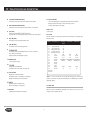
T 3 x
S E R I E S
O W N E R ’ S
T R E A D M I L L
M A N U A L
TABLE
1.0
OF
CONTENTS
1.1
1.2
1.3
IMPORTANT SAFETY INSTRUCTIONS
Proper Usage
Check for Damaged Parts
Important Safety Instructions
Electrical Requirements
Grounding Instructions
1
1
1
2
2
2.0
2.1
2.2
SETTING UP THE TREADMILL
Unpacking Treadmill
Contents
3
3
3.0
3.1
3.2
3.3
3.4
OVERLAY DESCRIPTION AND CUSTOM SETTING
Console Description
Engineering Mode
Manager Screen Description/Details
Using CSAFE
4
4
4
5
4.0
4.1
4.2
4.3
4.4
MAINTENANCE
Recommended Cleaning Tips
Deck and Belt Replacment
Adjusting the Belt
Maintenance Lamp
6
6
6
6
5.0
5.1
5.2
5.3
OPERATING THE PROGRAMS
Manual Operation
Operating Level Based Programs
Heart Rate Control
7
7
7
6.0
6.1
EQUIPMENT SPECIFICATIONS
Specifications
8
7.0
7.1
ASSEMBLY
Assembly & Hardware
9
1.0 IMPORTANT SAFETY INSTRUCTIONS
It is the sole responsibility of the purchaser of Matrix Fitness Systems products to instruct
all individuals, whether they are the end user or supervising personnel on proper usage of
the equipment.
1.1 IMPORTANT SAFETY INSTRUCTIONS
It is the recommended that all users of Matrix Ftiness Systems exercise equipment be
informed of the following information prior to its use.
This Treadmill is intended for commercial use. To ensure your safety and protect the equipment, read all instructions before operating the MATRIX treadmill.
PROPER USAGE
When using an electrical product, basic precautions should always be followed including
the following:
READ AND SAVE THESE INSTRUCIONS:
• Do not use any equipment in any way other than designed or intended by the manufacturer. It is imperative that all Matrix Fitness Systems equipment is used properly to
avoid injury.
• Keep hands and feet clear of moving parts at all times to avoid injury.
• Unsupervised children must be kept away from this equipment.
• Do not wear loose clothing while on equipment.
• When it is necessary to immobilize the treadmill, set the display to read “CHOOSE
PROGRAM USING QUICK KEYS OR SPEED UP OR DOWN KEYS”, then hold down the
RESET & ENTER keys. The treadmill will now display “IMMOBILIZED.” In this state the
treadmill can not be operated; both the drive motor & elevation motor are disabled. The
treadmill will remain in this state across power cycles, resets, etc. To return to normal
operation mode repeat the same key sequence, hold down the RESET & ENTER keys.
The display will now read “CHOOSE PROGRAM USING QUICK KEYS OR SPEED UP OR
DOWN KEYS”
DANGER To reduce the risk of electric shock:
Always unplug this equipment from the electrical outlet immediately after using and before
cleaning.
WARNING To reduce the risk of burns, fire, electrical shock or injury to persons that may
be associated with using this product:
• An appliance should never be left unattended when plugged in. Unplug from outlet when
not in use and before putting on or taking off parts.
• This product must be used for its intended purpose described in this Owner’s Guide. Do
not use other attachments that are not recommended by the manufacturer. Attachments
may cause injury.
• To prevent electrical shock, never drop or insert any object into any opening.
• Do not remove the side covers. Service should only be done by an authorized service
technician.
• Never operate the treadmill with the air opening blocked. Keep the air opening clean,
free of lint, hair and the like.
• Never operate product if it has a damaged cord or plug, if it is not working properly, if it
has been damaged, or immersed in water. Return the unit to a service center for examination and repair.
• Do not carry this unit by supply cord or use cord as handle.
• Keep any power cord away from heated surfaces.
• Keep hands and loose clothing away from moving parts.
• Close supervision is necessary when treadmill is used by or near children or disabled
persons.
• Do not use outdoors.
• Do not operate where aerosol (spray) products are being used or where oxygen is being
administered.
• To disconnect, turn all controls to the off position, then remove plug from outlet.
• Connect this treadmill to a properly grounded outlet only.
CHECK FOR DAMAGED PARTS
• DO NOT use any equipment that is damaged or has worn or broken parts. Use only
replacement parts supplied by Matrix Fitness Systems.
• MAINTAIN LABELS AND NAMEPLATES. Do not remove labels for any reason. They
contain important information. If unreadable or missing, contact Matrix Ftiness Systems
for a replacement.
• MAINTAIN ALL EQUIPMENT Preventative maintenance is the key to smooth operating
equipment, as well as keeping the users liability to a minimum. Equipment needs to
be inspected at regular intervals. Defective components must be replaced immediately.
Improperly working equipment must be kept out of use until it is repaired. Ensure that
any person(s) making adjustments or performing maintenance or repair of any kind is
qualified to do so. Matrix Fitness Systems will provide service and maintenance training
at our corporate facility upon request or in the field if proper arrangements are made.
CAUTION If you experience chest pain, nausea, dizziness or shortness of breath, STOP
exercising immediately and consult a physician before continuing.
1
1.0 IMPORTANT SAFETY INSTRUCTIONS
1.2 ELECTRICAL REQUIREMENTS
120V UNITS
For your safety and treadmill performance, the ground on this circuit must be non-looped.
Please refer to NEC article 210-21 and 210-23. Your Treadmill is provided with a power
cord with a plug listed below and requires the listed outlet. Any alterations of this power
cord could void all warranties of this product.
The Matrix MX-T3x 120 treadmill is for use on a nominal 120-volt circuit and has a nonlooped grounding plug. Make sure that the 110V treadmill is connected to an outlet, NEMA
5-20R, having the same configuration as the plug. No adapter should be used with this
product.
220V UNITS
The Matrix MX-T3x 220 treadmill is for use on a nominal 220-volt circuit and has a nonlooped grounding plug. Make sure that the 220V treadmill is connected to an outlet, NEMA
6-20R, having the same configuration as the plug. No adapter should be used with this
product.
120 NEMA 5-20R
220 NEMA 6-20R
120 NEMA 5-20R
220 NEMA 6-20R
1.3 GROUNDING INSTRUCTIONS
The treadmill must be grounded. If it should malfunction or breakdown, grounding provides
a path of least resistance for electric current to reduce the risk of electric shock. The treadmill is equipped with a cord having an equipment-grounding conductor and a grounding
plug. The plug must be plugged into an appropriate outlet that is properly installed and
grounded in accordance with all local codes and ordinances. If the user does not follow
these grounding Instructions, the user could void the Matrix limited warranty.
DANGER Improper connection of the equipment-grounding conductor can result in a risk
of electric shock. Check with a qualified electrician or serviceman if the user is in doubt
as to whether the product is properly grounded. Do not modify the plug provided with the
product if it will not fit the outlet; have a proper outlet installed by a qualified technician.
2
2 .0 SETTING UP THE TREADMILL
2.1 UNPACKING THE TREADMILL
2.2 CONTENTS
The MATRIX treadmill is inspected before it is packaged. It is shipped in four pieces: the
base, the upright console supports, the handlebar and the console. Carefully unpack the
unit and dispose of the box material.
1.
2.
3.
4.
5.
6.
CAUTION This unit weights 350 pounds. T
To avoid injury to the user and the unit, be sure
to have proper assistance to remove and move the unit.
Frame
Console Supports
Hardware Package
Handle Bar
Console
Power Cord
Console Support
Console
Hardware Package
Handle Bar
Power Cord
If any items are missing, please contact MATRIX FITNESS SYSTEMS customer service at 1-866-MXFITNESS.
3
3.0
3.1 CONSOLE DESCRIPTION
OVERLAY DESCRIPTION
AND
CUSTOM SETTINGS
3.2 ENGINEERING MODE
Engineering screens allow the viewing and editing of variables that would be necessary for
a club operator/manager to customize. Unless otherwise noted engineering screens consist
of the initial screen, the editing or action screen and the saving screen. The initial screen
displays the variable type and in most cases the current value. Edit or action screens are
where the editing of the variable(s) take place. The saving screen indicates the variable(s)
is being saved.
To access the Engineering screens press and hold the ELEVATION 'UP' and SPEED 'PLUS'
buttons for three seconds. The display will now display 'Engineering Mode'.
Use the ELEVATION UP or DOWN arrows to scroll through the different engineering
screens.
Press SELECT to edit the selected engineering screen.
Use the SPEED UP or DOWN arrows to set the variable.
SPEED KEY
QUICK-KEYS
Press START to save the selected variable.
3.3 MANAGER SCREENS EXCEPTIONS/DETAILS
PROGRAM KEYS Simple program view and selection buttons. Six programs to choose from
QUICK START/START One touch Start and Quick Start
SELECT To confirm each program setting
STOP Press the STOP key once to pause the program for 2 minutes. During the 2 minute
pause, press the QUICK START key to continue running the program, or else the machine will
reset automatically. Also, you can press and hold the STOP key to reset the treadmill.
UP/DOWN ELEVATION Easy information and elevation selection.
UP/DOWN SPEED Easy information and speed selection.
EMERGENCY STOP To stop all functions running
SPEED KEYS - NUMBERS Press the Speed Keys’ numbers to input program Time, Weight,
and Target Heart Rate
SPEED KEYS - RESET To cancel the numbers entered by the Speed Keys numbers
SPEED KEYS - ENTER To confirm each program setting
4
Below is a list of functions for each engineering screen. Exceptions will be noted in the
description for each engineering screens:
P0 LOW SPEED LEARN MODE (EDIT)
This variable controls the low limit for the speed of the treadmill.
P1 HIGH SPEED LEARN MODE (EDIT)
This variable controls the high limit for the speed of the treadmill.
P2 MIDDLE SPEED LEARN MODE (EDIT)
This variable controls the middle limit for the speed of the treadmill.
3.0
OVERLAY DESCRIPTION
AND
CUSTOM SETTINGS
P4 LOW ELEVATION LEARN MODE (EDIT)
This variable controls the low limit for the elevation of the treadmill.
P15 USER SPEED (EDIT)
Controls the starting speed for all programs (minimum speed not affected).
Displayed in native units (miles per hour or kilometers per hour).
Reverts to default value on unit change.
P5 HIGH ELEVATION LEARN MODE (EDIT)
This variable controls the the high limit for the elevation of the treadmill.
PRODUCT TEST
Test the product.
P6 UNITS (EDIT)
Changes from Standard (Miles) to Metric (Kilometers).
Unit change will force unit dependent variables to revert to their default values.
AUTO CHECK
Run auto calibration to calibrate speed and incline after assembly or to recalibrate speed
and incline values.
P7 LIMIT TIME (EDIT)
This variable controls the program maximum time.
ADDRESS
P8 USER TIME (EDIT)
This variable controls the default program time.
DESCRIPTION
DEFAULT
VALUE
MIN VALUE
MAX VALUE
P0
77
low speed learn mode
P1
600
high speed learn mode
P2
300
middle speed learn mode
P4
55
low elevation learn mode
P5
200
high elevation learn mode
P6
MPH
MPH
KPH
units
P7
90:00:00
10:00
90:00:00
limit time
P8
20:00
10:00
90:00:00
user time
P9
KPH:80/MPH:150 KPH:22/MPH:50 KPH:180/MPH:400
set weight
P10
Matrix T3x
Matrix T3x
JOHNSON T8000
machine
P11
total time
P12
total dist
P13
version
P14
English
English
Holland
language
P15
1.0
.5
1.5
user speed
Product Test
Auto Check
P9 SET WEIGHT (EDIT)
This variable controls the default weight used in the calorie calculations.
Sets to default on unit change.
Displayed in native units (kilorgram or pounds)
P10 MACHINE (EDIT)
Controls the product name.
P11 TOTAL TIME
Displays total accumulated time.
Accumulated time is not editable, for display only.
P12 TOTAL DISTANCE
Displays total accumulated distance.
Accumulated distance is not editable, for display only.
Displayed in native units (miles or kilometers).
NOTE: P0, P1 and P2 are auto start. The belt will start moving once the SELECT key is
pressed. Once the value is saved press the ELEVATION UP or DOWN key to increase the
engineering variable.
P13 VERSION
Displays the product's software version.
Version is not editable, for display only.
3.4 USING CSAFE
P14 LANGUAGE
Language in which information is displayed.
Matrix is the leader in entertainment availability. On the back of the console is an RJ45
receptacle. They are marked CSAFE IN.
5
4.0 MAINTENANCE
4.1 RECOMMENDED CLEANING TIPS
STEP 1 Locate the two hex head bolts on the rear of the treadmill. The bolts are located
at each end of the frame at the back of the treadmill. These bolts adjust the rear
belt roller. Do not adjust until the treadmill is on. This will prevent over tightening of one side.
STEP 2 The belt should have equal distance on either side between the frame. If the belt
is touching one side, do not start the treadmill. Turn the bolts counter clockwise
approximately one full turn on each side. Manually center the belt by pushing
the belt from side to side. Tighten the bolts the same amount as when the user
loosened them, approximately one full turn. Inspect the belt for damage.
STEP 3 While the treadmill is running at 3 mph, observe the belt position. If it is moving
to the right, tighten the right bolt by turning it clockwise ¼ turn, and loosen the
left bolt ¼ turn. If it is moving to the left, tighten the left bolt by turning it clockwise ¼ turn and loosen the right ¼ turn. Repeat Step 3 until the belt remains
centered for several minutes.
STEP 4 Check the tension of the belt. The belt should be very snug. When a person walks
or runs on the belt, it should not hesitate or slip. If this occurs, tighten the belt
by turning both bolts clockwise ¼ turn. Repeat if necessary.
1. Use a soft, clean cotton cloth. DO NOT use paper towels to clean surfaces on the
treadmill. Paper towels are abrasive and can damage surfaces.
2. Use a mild soap and damp cloth. DO NOT use ammonia based cleaner. This will cause
discoloring of the aluminum and plastics it comes into contact with.
3. Do not pour water or cleaning solutions on any surface. This could cause electrocution.
4. Wipe the console and side rails after every use.
5. Brush away any wax deposits from the deck and belt area. This is a common occurrence
until the wax is worked into the belt material.
6. Be sure to remove any obstructions from the path of the elevation wheels including
power cords.
7. Monthly, unplug the treadmill and remove the motor cover. Check for debris and clean
with a dry cloth or small vacuum nozzle. WARNING: Do not plug the treadmill in until
the motor cover has been reinstalled.
CAUTION This unit weighs 350 pounds. Be sure to have proper assistance to install and
move the unit in order to avoid injury to you or the unit.
4.4 MAINTENANCE LAMP
4.2 DECK AND BELT REPLACEMENT
There is a maintenance lamp on the console to remind the owner to do the scheduled
maintenance. When the treadmill's accumulated distance reaches 5000 miles, the maintenance lamp will light meaning maintenance is needed. The following is the maintenance
lamp key;
• Blue: It means that the treadmill needs to be maintained. To turn off maintenance light
after performing service, hold the INCLINE DOWN and SPEED DOWN at the same time for
3 seconds.
• Red: It means that the treadmill might have some problems, and needs to be checked.
Please contact MATRIX customer service.
One of the most common wear and tear items on a treadmill is the Deck and Belt combination. If these two items are not properly maintained they can cause damage to other
components. This product has been provided with the most advanced maintenance free
lubricating system on the market.
WARNING: Do not run the treadmill while cleaning the belt and deck. This can cause serious injury and can damage the machine.
Maintain the belt and deck by wiping the sides of the belt and deck with a clean cloth. The
user can also wipe under the belt 2 inches on both sides removing any dust or debris.
The deck can be flipped and reinstalled or replaced by an authorized service technician.
Please contact Matrix Fitness Systems for more information.
4.3 ADJUSTING THE BELT
After placing the treadmill in the position it will be used, the belt must be checked for
proper tension and centering. The belt might need to be adjusted after the first two hours
of use. Temperature, humidity, and use cause the belt to stretch at different rates. If the
belt starts to slip when a user is on it, be sure to follow the directions below.
6
5.0
OPERATING
THE
PROGRAMS
5.1 MANUAL OPERATION
5.3 HEAT RATE CONTROL
MATRIX design makes using the programs as easy as one touch of a button.
Follow these easy Steps to enter into the Heart Rate Program.
QUICK START
Press the “QUICK START” key and the LED will show “3”, “2”, “1”, “GO!”. The treadmill
will start running from the lowest incline and 0.5 mph, with the default time counting
down from 20 minutes.
TARGET HR
T
1) Choose the “TARGET HR” program using the program QUICK-KEYS, then press SELECT.
2) Choose your TARGET HEART RATE using the SPEED -/+, then press SELECT.
3) Choose your HR CONTROL MODE using the SPEED or INCLINE KEYS:
- If SPEED -/+ is pressed the console will display “Speed HR Control, press - or + to set
Max Speed, then press SELECT”.
- If INCLINE UP/DOWN is pressed the console will display “Incline HR Control, press up
or down to set Max Incline, then press SELECT”.
4) Choose TIME using SPEED -/+, then press SELECT.
5) Choose WEIGHT using SPEED -/+, then press SELECT.
6) Press START..
MANUAL MODE allows you to enter desired time, level and weight.
1)
2)
3)
4)
Choose the “MANUAL” program using the program QUICK-KEYS, then press SELECT.
Choose the TIME using SPEED -/+, then press SELECT.
Choose WEIGHT using SPEED -/+, then press SELECT.
Press START.
TARGET HEART RATE is determined by the following formula.
(220 Beats Per Minute - Age) Selected precentage.
Example (220 - 30) 65% = 123 Beats Per Minute.
Select from 50% - 80% in 5% increments.
5.2 OPERATING LEVEL BASED PROGRAMS
Your MATRIX Treadmill offers versatile programs to keep the user motivated. The following
instructions will guide you through simple steps to select INTERVALS, FAT BURN and 5K
RUN programs.
INTERVAL, WEIGHT LOSS & FAT BURN
1)
2)
3)
4)
5)
Choose the program using the program QUICK-KEYS, then press SELECT.
Choose the LEVEL using SPEED -/+, then press SELECT.
Choose the TIME using SPEED -/+, then press SELECT.
Choose WEIGHT using SPEED -/+, then press SELECT.
Press START.
5K RUN
1)
2)
3)
4)
Choose the “5K” program using the program QUICK-KEYS, then press SELECT.
Choose the LEVEL using SPEED -/+, then press SELECT.
Choose WEIGHT using SPEED -/+, then press SELECT.
Press START.
7
6.0
EQUIPMENT SPECIFICATIONS
6.1 SPECIFICATIONS
Foot Print
Weight
Max User Weight
Belt Type
Frame Construction
Running Area
Incline Range
Speed Min.
Speed Max.
Motor Type
Controller Cooling Fan
Electrical Receptacle
Electrical Plug
Electrical Receptacle
Electrical Plug
Electrical Amps
Electrical Amps
Deck
Wax
HEART RATE
inches = 85” x 34” x 55”
cm = 216 x 87 x 140
350 lbs
159 kg
400 lbs = 181 kg
Habisat
Steel
20” x 60”
15%
0.5
12
DC
Yes
120 NEMA 5-20R
120 NEMA 5-20P
220 NEMA 6-20R
220 NEMA 6-20R
120v 20 Amps
220v 10 Amps
1” Reversible
No Maintenance
VARIABLE COMPRESSION TECHNOLOGY
Absorber
Number of Cushions
Cushion = Stride Impact
Rubber Dampeners
8
Yes
SAFETY
Shut off w/Tether
Large Safety Stop
Yes
Yes
PROGRAMS
Number Key Pad
One Button Quick Start
Target Heart Rate
Fat Burn
Intervals
5k Run
8
Yes
Yes
Yes
Yes
Yes
Yes
Telemetry
Contact Heart Rate
Yes
Yes
ENTERTAINMENT READY
CSAFE Port
1
7.0
ASSEMBLY
7.1 ASSEMBLY & HARDWARE
• ATTENTION
After installation is completed, the treadmill will need to be calibrated by using the AUTO-CHECK
function. If this is not done, the treadmill's speed and incline values may be incorrect and damage the
treadmill. Do not stand on the belt when performing the AUTO-CHECK function.
• ASSEMBLY INSTRUCTIONS
To ensure correct assembly of the treadmill, carefully read and follow these steps:
Please make sure that the power plug is not plugged into the wall outlet while completing the following
procedure.
STEP 1
REF #
DESCRIPTION
QTY
Z01
Screw Driver
1
Z02
Wrench (M8)
1
Z03
Wrench (M10)
1
Z50
Washer (30x2.0t)
8
Z51
Screw, Socket Head (M10x25L)
8
Z52
Screw, Socket Head (M8x30L)
4
Z53
Screw, Socket Head (M5x12L)
2
STEP 2
Z51
Z50
Z52
Z50
Z51
Z52
Remove the motor cover. Pull out the console cable and route it through the Right
console mast. Place the right console mast and then the left console mast in the
console post support brackets. Secure the Right and Left mast with the 4 bolts
provided (Z50, Z51). Make sure these bolts are tight.
Connect the console cables from the console set to the motor control board
cables. Secure the console set with 2 screws (Z52) on each side.
9
7.0
ASSEMBLY
7.1 ASSEMBLY & HARDWARE
STEP 3
STEP 4
Z53
N06
Z53
N07
Put the handle bar into the handle bar frame. Use the handle bar cap (N06,
N07) to secure the handle bar. The handle bar caps are separate right and left,
make sure these caps are in the correct position.
Place the motor cover onto the treadmill front end and secure with the screws (Z53) provided. Plug the power
cable into the outlet.
STEP 5
AUTO CHECK
• Press and hold both incline “UP” and speed FAST buttons simultaneously for 3 seconds .Then the “ENGINEERING MODE” is shown onto the console.
• Press the incline “UP” button to find the “AUTO CHECK” screen.
• Press the incline “SELECT” button and then, the treadmill will run the auto check function automatically. This will take around 3 minutes to run.
• After auto check is complete “AUTO CHECK OK” will show on the console. Then, press EMERGENCY STOP key to back to initial starting screen.
10