1
1
V2.0
DEP/JMK
15 May 1997
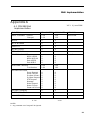
This equipment has been tested and found to comply with the following European and international Standards
for Electromagnetic Compatibility and Electrical Safety:
Radiated Emissions (EU):
RF Immunity (EU):
Mains Disturbance (EU):
Electrical Safety (EU):
Radiated Emissions (USA):
Electrical Safety (USA):
Electrical Safety (CAN):
EN55013
(1990)
EN50082/1
(1992)
EN61000/3/2
(1995)
EN60065
(1993)
FCC part 15 Class B
UL813/ETL
(1996)
UL813/ETLc
(1996)
Associated Equipment
RF Immunity, Fast Transients ESD
Commercial Audio Equipment
Commercial Audio Equipment
IMPORTANT SAFETY INFORMATION
DO NOT REMOVE COVERS. NO USER SERVICABLE PARTS INSIDE, REFER SERVICING TO QUALIFIED
SERVICE PERSONNEL. THIS EQUIPMENT MUST BE EARTHED.
IT SHOULD NOT BE NECESSARY TO REMOVE ANY PROTECTIVE EARTH OR SIGNAL CABLE SHIELD
CONNECTIONS TO PREVENT GROUND LOOPS. ANY SUCH DISCONNECTIONS ARE OUTSIDE THE
RECOMMENDED PRACTISE OF BSS AUDIO AND WILL RENDER ANY EMC OR SAFETY CERTIFICATION
VOID.
For continued compliance with international EMC legislation ensure that all input and output cables are wired
with the cable screen connected to Pin 1 of the XLR connectors and/or the jack plug sleeve. The input XLR Pin
1 and the side-chain input jack socket sleeve are connected to the chassis via a low value capacitor, providing
high immunity from ground loops whilst ensuring good EMC performance.
We have written this manual with the aim of helping installers and sound engineers to get to grips with the
Omnidrive and obtain its maximum capability. If you are new to BSS products, we recommend that you begin
at the start of the manual.
We welcome any comments or questions regarding the Omnidrive or other BSS products, and you may contact
us at the address or World Wide Web site given in the warranty section.
2
Quick Start
Quick Reference
Quick Start - Quick Reference
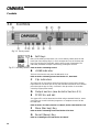
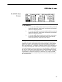
1
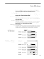
Check the Mains Voltage setting on the rear of the FDS-388/380 Omnidrive and
install into a rack. Connect the mains to the unit and check that it powers up.
2
Connect the two audio inputs and up to eight audio outputs. Do not put any audio
through the unit at this time.
Refer to Sections 2.0 thru 2.7 'Installation'
FDS-388
Omnidrive
FDS-380
Install
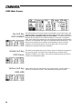
1
The user will need to load a program suitable for the PA system in use. Some units
will come locked to a specific PA system. In this case most controls will be disabled and the unit will be ready for use. If the unit has a blank display or 'OWNER'
on the default screen, then the unit has been pre-programmed and software
locked and is also ready for use.
2
If the FDS-388 is not locked in one of these ways, the user may need to load a
program specific for the PA system by recalling it from memory or by loading a
file from a smart card. Alternatively recall program 0 (default) and program as in 5
below.
3
To load a file from memory press RECALL while in the default screen; the first
screen after the logo has disappeared. Use the parameter wheel to scroll through
the available programs. Programs marked with diamonds are "OEM" programs and
have been designed to match specific PA systems. Press the RECALL key again to
recall the selected program. If there is no program suitable then the user will need
to set up the unit from scratch to suit the PA manufacturers specification after
recalling program 0, or obtain a program on a smart card.
4
To load a file from smart card press RECALL while in the default screen. Press the
middle soft key on the left of the display. Turn the encoder to make the middle soft
key show 'Cprg' (Card program). Press the top soft key ('PICK') and turn the
encoder to select the program from the card. A second press of RECALL will load
the program. The user should now store the settings in internal memory for future
use. Refer to Section 15.0, Store Screen.
5
To adjust individual band levels, use the front panel trim controls.
For information on the FDS-380 Install version of the Omnidrive Refer to Section 21.0,
FDS-380 Install.
1
Set the Midi channel number of the FDS-380 Omnidrive Install using the two
recessed keys at the left hand end of the unit. To load a complete XAL file the file
should be named LOADmm.XAL where mm is the midi channel number e.g.
LOAD01.XAL if the unit's midi channel is 1. The file will be loaded when the card
is inserted into the card slot - the user is given a 3 second warning countdown
before the contents of the FDS-380 are overwritten. If the filename is wrong, an
error number will be displayed. Refer to Section 21.0 FDS-380 Install.
Please Read Overleaf...
3
Please Read This!
Using This Manual
Please Read This! - Using This Manual
This manual has been written to make the understanding and operation of the
FDS-388 Omnidrive as easy as possible. Because the Omnidrive is a relatively
sophisticated software product, we have included several ways to find the
information you require in this manual. You will have already found a Quick
Reference on the previous page to get the user going from scratch. These
instructions are by no means all there is to know and references are made to
the main body of the manual for extra detail.
Table of Contents
Quick Reference
"Refer to:"
The Contents now begins on Page 3, opposite this one. The chapter and
section names are generally those of the important Keys and Controls on the
Omnidrive. This is a good place to find whole sections, for example Delay or
Recall.
Once you have found the appropriate chapter there is often a Quick Reference
section. This will give abbreviated instructions for the use of the key or control.
These can remind the user of a control’s operation if the section has already
been read.
Throughout the text there are references to other areas in the following form.
Refer to Section 16.0, Recall Screen.
These will help to tie together different places where the same keys are used
for different purposes. They are also used heavily in Section 3.0 ‘Controls’....
"Section 3.0
Controls"
Index
Section 3.0 has drawings of the front panel of the FDS-388 Omnidrive. Each is
annotated and reference to the appropriate letter will give a brief description of
the item and usually a reference to the section in the manual where the item is
detailed at greater length.
Finally, when you need to refer to a particular feature quickly, the Index may
be the quickest way. The Index can be found at the end of the manual, after
the appendices.
Please feel free to give us your comments on this manual and any ideas you
may have for further improvement. Although we make every effort to ensure
that this manual is correct, there may have been recent improvements made in
the software which are not reflected in this manual.
4
Contents
Contents
1.0
1.2
1.1
2.0
2.1
2.2
2.3
2.4
2.5
2.6
2.7
3.0
3.1
Introduction
7
Other features
OMNIDRIVE TM Loudspeaker Management
System
7
7
Installation
8
Unpacking
Mechanical Requirements
Mains Power
Voltage Setting
Safety Earthing
AC Power Fusing
Rear panel
Controls
Output Section
8
8
9
9
10
10
11
12
14
4.0
Getting Around the FDS-388
15
5.0
Default Screen
20
6.0
Default Utility Screen
22
7.0
Delay Screen
24
8.0
Delay Utility Screen
26
9.0
EQ Screen
28
EQ Utility Screen
30
10.0
10.1
Dynamic Filter.
31
11.0
XOver Screen
32
12.0
XOver Utility Screen
34
13.0
XOver More Screen
36
14.0
Store and Recall
38
14.1
14.2
15.0
15.1
15.2
Store and Recall in the Default Screen
Store and Recall in an Edit Screen
Store Screen
Locking Programs
Front Panel Trim Settings
38
38
39
40
40
5
Contents
16.0
Recall Screen
41
17.0
File Utility Screen
42
18.0
PCMCIA Card
43
Smart Card Format
Card Types
43
43
System Security
45
18.2
18.1
19.0
19.1
19.2
19.3
19.4
19.5
19.6
Program Lock
Lock Mode On
OWNER Lock
OEM Lock
Safe
OEM Hide Screen
45
45
45
46
46
47
20.0
Meteorology
49
21.0
FDS-380 Omnidrive Install
50
21.1
21.2
21.3
FDS-380 Controls
Midi Operation
PC Card Operation
50
51
51
22.0
Service section
52
22.1
22.2
23.0
A.1
A.2
Transient Suppressor Replacement
100V Tap Conversion
52
53
Warranty Information
54
Appendix A
55
FDS-388 Midi Implementation
Specification and Block Diagram
55
56
Appendix B
FDS-380/FDS-388 Messages
57
Appendix C
C.1
C.2
C.3
C.4
6
AES3 Input and Input/Output Boards
Fitting The AES3 Input Board
AES3 Input Board Operation
Fitting The AES3 Input/Output Board
AES3 Input/Output Board Operation
58
58
59
59
60
Index
61
User Notes
64
Introduction
1.0
Introduction
1.1 OMNIDRIVE TM
Loudspeaker
Management
System
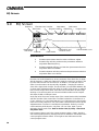
The OMNIDRIVETM system represents a radical step forward in DSP processing
for loudspeaker management, incorporating BSS’s vast experience in crossover
design and combining two channels of 4-way crossover, parametric
equalisation, digital delay lines and limiters, and is designed for use in all areas
of sound control. A compact 2U chassis means reduced interconnections
cabling and rack weight, while increasing rack space availability. Major
facilities include password protection, automatic correction for HF response
with humidity and delays with temperature.
The user front-end is remarkably simple, combining a real-time graphical
display with an analogue-like output control section with led meters for full
indication of system performance. The screen shows crossover response, EQ
curves plus delay and limiter data in high-resolution graphics. System settings
can be stored in up to 60 user memories, for quick and easy setup.
The crossover sections can be configured as stereo 2, 3 or 4 way, with the
option of setting one stereo band as a mono-lo output for sub-bass processing.
Various filter types may be selected with slopes of 12, 18 or 24dB per octave.
Parametric EQ is provided as two sections of fully adjustable EQ per band of
processing, one section being optionally configured as a 0-180 degree
adjustable phase control, with polarity switching as standard through a
separate independent function. The EQ range is 15Hz to 16kHz, gain
adjustable +/- 15dB, with a Q from 0.05 to 3 octaves, switchable between bell
or shelving response.
The limiters are located mid-band, an optimal configuration originated by BSS
and now widely adopted. Each band also incorporates a delay line, with
adjustable delay in unusually fine 10 microsecond steps up to 650 milliseconds
and displayed and adjusted in feet, metres or milliseconds.
1.2 Other features
Data Archive to PCMCIA memory card.
Optional Digital I/O cards.
Optional Humidity / Temperature probe for auto correction system.
MIDI Interface / Open Architecture port.
7
Installation
Unpacking
Mechanical Requirements
2.0
Installation
2.1 Unpacking
As part of BSS Audio Ltd’s policy of quality control, this product is carefully
checked before packing to ensure flawless appearance and that it reaches you
in first class condition.
After unpacking the unit, please inspect it for any physical damage. If any
damage has occurred, notify your dealer immediately. A written claim for
damages can then be initiated. The Warranty, Section 21.0, at the end of the
manual gives more information.
Please retain the shipping carton and all the packing materials for use should
the unit need to be transported or returned for any reason.
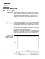
2.2 Mechanical
Requirements
The FDS-388 requires a vertical rack space of 2U (3.5" 88mm). The unit should
be supported at its rear by additional bracing or shelving if it is to be used in a
transportable system. Failure to do so may damage the case and invalidate the
warranty. Fig 2.1 details the relevant dimensions and fixing centres for the
FDS-388.
Adequate ventilation must be provided by allowing sufficient space around the
sides and rear of the FDS-388 to ensure free circulation of air. Forced cooling
is not required. Note that the FDS-388 has a cooling fan mounted on the right
hand side of the case when viewed from the front.
Before connecting the FDS-388 to an AC power source, check that the voltage
selector switch on the rear panel is correctly set. If a change is necessary then
ensure that the mains fuse is changed for one of the correct current rating
Fig 2.1 Overall
dimensions of the
FDS-388 Omnidrive
8
Mains Power
Voltage Setting
2.3 Mains Power
Refer to Section 2.6 'Installation' - AC Power and Fusing.
WARNING! THIS APPLIANCE MUST BE EARTHED.
IMPORTANT: The wires in the mains lead are colour coded in accordance
with the following code.
Green and Yellow......Earth
Blue......Neutral
Brown......Live
As the colours of the wires in the mains lead may not correspond with
the markings identifying the terminals in your plug, proceed as
follows.
! The wire which is coloured Green and Yellow or Green must be connected
to the terminal which is marked with the letter ‘E’ or by the Earth
signal
or which is coloured Green and Yellow or Green.
" The wire which is coloured Blue must be connected to the terminal labelled ‘N’ or coloured Black or Blue.
# The wire which is coloured Brown must be connected to the terminal
labelled ‘L’ or coloured Red or Brown.
Those units supplied to the North American market will have an integral
moulded 3 pin connector which is provided to satisfy required local standards.
2.4 Voltage Setting
The mains voltage selector switch provides a simple external adjustment to
allow operation on all international AC power standards. The allowable ranges
for the supply voltage are:
99VAC up to 121VAC on the 120V position and
204VAC up to 264VAC on the 240V position.
An additional internal tap change is available for 100V working. Refer to
section 22.0; Service section. The tap change gives:
90VAC up to 110VAC on the 120V position
Outside these ranges the unit will not work satisfactorily, if at all. Voltages in
excess of the maximum will probably cause damage. Voltages below the
minimum will cause the power supplies to drop out of regulation, degrading
the performance of the system. The battery in the unit will preserve all data in
the event of a power failure.
9
Safety Earthing
AC Power Fusing
2.5 Safety Earthing
2.6 AC Power
Fusing
The Green and Yellow wire of the mains cord must always be connected to an
installation Safety Earth or Ground. The Earth is essential for personal safety as
well as the correct operation of the system, and is internally connected to all
exposed metal surfaces. Any rack framework into which this unit may be
mounted is assumed to be connected to the same grounding circuit.
The incoming mains power is fused within the FDS-388 by the fuse holder
mounted on the rear panel. Should it be necessary, the fuse must be replaced
by one of the same size and current rating.
20mm T250mA for the 240V setting
20mm T500mA for the 120V setting
It is most important for continued safety that this specification is strictly
adhered to. Spare fuses of the correct rating are supplied with the unit from
new.
It is unlikely that the AC fuse will fail during normal use and caution should be
exercised if it does. The most likely reason at first power up is the incorrect
setting of the mains voltage switch on the rear panel. Alternatively the unit may
have been connected across two lines of a three phase supply. In both of these
cases the internal transient suppressors may have been damaged and will
continue to blow replacement fuses, even if the supply is now correct. The
suppressors will have protected the FDS-388 Omnidrive from damage and
need replacing before the unit can be used again.
Refer to section 22.0; Service section for the replacement procedure.
10
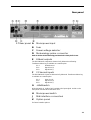
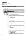
Rear panel
2.7 Rear panel A
Mains power input
B
Fuse
C
Power voltage selector
D
Meteorology probe connector
Refer to Section 20.0 Meteorology and Section 8.0 Delay Utils Screen.
E
8 Band outputs
The FDS-388 audio outputs are electronically balanced and floating.
Transformer balancing is available as a retrofit option.
Pin 1
Pin2
Pin3
F
Shield/Ground
Signal Hot (+)
SignalCold (-)
2 Channel inputs
The FDS-388 audio inputs are electronically balanced. Transformer balancing
is available as a retrofit option.
Pin 1
Pin2
Pin3
G
Open circuit
Signal Hot (+)
SignalCold (-)
+10dB switch
With this switch in, 10dB of gain is added to the input signal. An led on the
front panel indicates when this switch is on.
H
Mains power switch
J
Midi interface connectors
K
Option panel
For future interface options.
11
Controls
3.0
Controls
Fig 3.1 Front panel
A
Soft Keys
Many of the editing screens have one or more soft key labels down the left
hand side of the display (Fig 3.2). Each corresponds to one of the three soft
keys. The soft keys are most often used to select a type of parameter. The
individual parameter to adjust is selected by pushing the encoder.
Fig 3.2 Soft Key labels Refer to Section 4.0 Getting Around
B
+10dB indicator
This led is lit when the rear panel +10dB switch is on.
Refer to Section 4.0 Getting Around and Section 2.7, Rear Panel.
C
Clip indicators
The upper pair of clip leds are driven from the input circuitry and indicates
input overload. The lower pair of clip leds indicates overload at one of several
points through the dsp circuitry. Overload in the dsp section is most often
caused by large eq filter boosts.
D
Output section (see detail in Section 3.1)
E
PCMCIA card slot
Two types of file can be stored and recalled using a standard PCMCIA 'smart'
card. Files can contain individual programs or a complete record of all the
FDS-388 data.
Refer to Section 15.0 Store, Section 16.0 Recall, Section 18.0 PCMCIA Card.
F
Store (Backup) Key
Refer to Section 4.0 Getting Around and Section 15.0 Store.
G
Recall (Swap) Key
Refer to 4.0 Getting Around and Section 16.0 Recall
12
Controls
H
Utility Key
The Utility Key takes the user in and out of each edit screen's utility area. The
led is lit when in a utility screen.
Refer to Section 4.0 Getting Around
J
Left/Right/Split Keys
These keys control which channel or channels the user is adjusting and which
channel is viewed. The leds serve to indicate whether the left and right
channels are set with the same values.
Refer to Section 4.0 Getting Around
K
Edit Key
This key determines which of the three editing screens the user is in. The three
screens are:
Delay
For setting band delays, phase adjustments and polarities.
EQ
For setting equalisation for each band
XOver
For adjusting band crossover frequencies and slopes and for
setting band gains and limiter thresholds.
Each screen has an associated blue led which is on whilst the user is in the
screen or a related utility screen.
A fourth press of the Edit Key takes the user back to the Default screen.
NOTE Pressing and holding the Edit Key in any screen will take the user
straight back to the Default screen.
Refer to Section 4.0 Getting Around
L
Encoder (Parameter Wheel)
Pushing the parameter wheel will step around the current type of variables
allowing the user to select one to adjust.
Pressing and then turning the parameter wheel while still pressed will move
the highlight backward and forward through the current type of variables.
Turning the parameter wheel will adjust the currently selected variable.
13
Output Section
3.1 Output Section
Fig 3.2 Output Section
A
Mono led
The Mono led reflects the status of the Mono Lo parameter which is set in the
XOver Utility Screen.
Refer to Section 12.0, XOver Utility Screen - Mono Lo
When the led is on, the left and right A bands are summed to produce a mono
output. For example a mono low frequency output.
B
C
Output meter
Meter legend
The output meters are referenced to the band limit threshold. If, for example,
the limiter threshold is set to +4dBu then the -3dB led will come on at +1dBu.
The Limit led is lit when the signal reaches the limit threshold. The Over led
lights at 6dB above the limit threshold when the limiter is on and is left on
permanently when the limiter is switched off as a warning.
Refer to Section 11.0, XOver Screen - Limit.
E
Gain trim
Each output band can be trimmed for output level across a range of
+6dB.
–6dB to
Note that when programs are stored and the Store Trims option is ON, the
front panel gain trim values are added into the stored gain values. Store Trims
is a user selectable option.
Refer to Section 15.0 Store for more information.
D
Mute led
F
Mute key
Pressing a mute key will toggle the associated band output on and off. The
mute led is illuminated when the associated output is muted. Mute status is
saved when a program is stored.
14
Getting Around the FDS-388
Split, Left and Right Keys
4.0
Getting Around the FDS-388
4.1 Split, Left and
Right Keys
The Split keys (Left and Right) are used to select which of the two channels in
the FDS-388 is being displayed and whether the user wishes to control one or
both of the channels simultaneously.
Linked Operation
The two leds indicate whether the FDS-388 channels are linked and controlled
together or split and controlled individually. If both split leds are on
continuously then the two channels have identical parameter values
throughout and are linked together when any parameter is adjusted. If one led
is flashing then the parameter values for left and right are different. The led that
is NOT flashing is the one which is being controlled and displayed on the
screen. The user can switch between the channels to see the parameter values
for left and right whilst linked but both parameters are adjusted when the
encoder knob is turned.
Split Operation
If only one led is on then only one channel can be adjusted and displayed at a
time. This could be used, for example, for making fine adjustments to one side
of a stereo pair. The led that is on indicates the controlled and displayed
channel. The user can select between the two channels by pressing the
individual L and R buttons. Once the user has pressed the two Split keys to
return to linked operation, one of the leds will flash to show that the two
channels now have different parameter values.
There are several important points to note about the Split mode operation.
$ The FDS-388 was designed primarily as a stereo unit. All programs and
card files are stored as Left and Right pairs and it is not intended for the user
to be able to store the two channels independently. The user can program
the two channels for quite different purposes (e.g. Left front of house and
left delay tower in one FDS-388) but he or she should be aware that the
complete setup will be stored in a single stereo program.
% The left and right split leds will not flash if the left and right mutes or gain
trims are set differently.
& Parameter value can be set to different values while in split operation and
will hold those different values when the unit returns to linked operation.
When the parameter is now adjusted in linked mode the left and right
parameters behave in one of two ways depending on what type of parameter is being controlled.
Variable parameters such as a filter frequency or a gain value will move
with the offset between the left and right values preserved. If either value,
left or right, hits the limit of the parameter’s travel then the parameter
cannot be moved further. The offset is preserved.
Switched parameters such as the Bell/Shelving switch in the EQ Utility
section will jump to the same, displayed value when the parameter is
adjusted.
15
Moving Around the Screens
Fig 4.0 FDS-388 Key
Map
4.2 Moving Around
the Screens
Quick Reference
Pressing the EDIT key shifts the screen through each of the main
editing areas in turn and then back to the main ‘Default’
screen.
Pressing and holding the EDIT key will take the user back to the
main ‘Default’ screen from any edit screen.
Pressing the UTILITY key shifts in and out of each edit screen’s
utility page.
16
Moving Around the Screens
The Soft keys have different operations depending on the current screen. Two lines of text for each key on the left hand
side of the screen label the key’s function.
Turn the encoder knob to adjust the currently selected variable.
Press the encoder knob or press and turn the encoder knob to
move between the available variables.
17
The Edit Key
The Utility Key
After powering up, the FDS-388 performs internal checks and sets up the audio
path before releasing the output mute relays. The time before the mute relays
open can be set in the Default Utility screen. Refer to Section 6.0, Default
Utility Screen.
The screen that the FDS-388 now shows is called the Default screen. This
shows the overall frequency response of the four output bands and the current
program information. The Default screen is covered in more detail in Section
5.0, Default Screen.
The EDIT Key
The EDIT key steps through the three main parameter editing screens. See Fig
4.0, FDS-388 Key Map.
DELAY, where the user adjusts band delays and the overall delay for the unit,
the polarity of each band and the phase adjustment at each crossover point.
Refer to Section 7.0, Delay Screen.
EQ, where the user can setup the two equalisers available in each output band.
Refer to Section 9.0, EQ Screen.
XOVER, where the user can adjust the crossover frequencies of the channel
and the internal gain and limiter thresholds for each band. Refer to Section
11.0, Xover Screen.
The blue leds above the EDIT key always show which of the three edit areas
the user is in.
The UTILITY Key
The UTILITY key takes the user into the related utility screen for each of the
three edit screens, the default screen and the Store/Recall screen. Each utility
menu has a number of setup and control parameters which are associated with
their edit screen. Pressing EDIT while in a utility screen will take the user to the
next utility screen in the loop (Default to Delay to EQ to Xover and back to
Default). See Fig 4.0, FDS-388 Key Map.
The Default Utility has entries for midi setup, contrast and brightness, input and
sample rate selection, power up time and the unit lockout selector. Refer to
Section 6.0, Default Utility Screen.
The Delay Utility has entries for temperature and humidity control, units for the
delay values and a facility to link two or more band delays together. Refer to
Section 8.0, Delay Utility Screen.
The EQ Utility Screen has entries to set whether each filter is bell or shelf and
to set the parameters for the dynamic equaliser. Refer to Section 10.0, EQ
Utility Screen.
18
The Soft Keys and Encoder
Store and Recall
The Xover Utility Screen sets the master slope (in dB per octave) and the shape
(Linkwitz-Riley, Butterworth or Bessel) for all crossover edges. Mono low on
and off, and the units for the limiter values are also set here. Pressing the Top
Soft key in the Xover Utility screen takes the user to the Xover More screen.
Refer to Section 12.0, Xover Utility Screen.
The Xover More Screen allows the user to adjust individual crossover edge
frequencies and slopes and also to select a name for each of the four bands
from a preset list of names. Refer to Section 13.0, Xover More Screen.
Pressing Utility whilst in the Store or Recall screens takes the user to the File
Utility Screen where files can be deleted, the smart card can be formatted and
individual programs can be locked against accidentally being overwritten.
Refer to Section 14.0, Store and Recall, and Section 17.0, File Utility Screen.
The Soft Keys and
Encoder
The soft keys and encoder push together allow the user to select the variable to
adjust. The soft keys generally select a type of variable to adjust. For example
in the Delay screen, pressing the middle soft key moves the highlight to one of
the band delay values. Pressing the encoder now moves the highlight around
the four band delays. Turning the encoder will adjust the currently highlighted
variable. To move around the available variables more quickly the user can
push and turn the encoder while the encoder is held in. This is particularly
useful for moving backwards through a variable list as the encoder push only
moves in one direction.
Store and Recall
As the Store and Recall screens are similar they are treated together with key
arrows called STORE or RECALL in fig 4.0, FDS-388 Key Map.. Also, note that
the STORE and RECALL keys have different operations depending on whether
the user is in one of the Edit screens or in the Default screen. In the Default
screen the STORE or RECALL keys will store or recall programs to the internal
memory or the Smart card. When they are pressed in one of the edit screens,
they serve to transfer the current program to and from a Backup or 'scratchpad'
program allowing A-B comparisons when making changes. Refer to Section
14.0 Store and Recall.
19
Default Screen
5.0
Default Screen
Program number
Status
Swap status
Edited flag
Band response curves
OEM name
Program name
Humidity correction
Quick Reference
1
Press the EDIT key to enter the edit screens.
2
Press STORE or RECALL for the file handling screens.
When the FDS-388 is powered up the Default screen is shown. The Default
gives a basic representation of the current state of the unit. If the unit has
Owner Lock On, the Default screen will be replaced by the current start up
logo along with the current program name and number.
The main area of the screen contains the four output band curves and the
humidity correction (if switched on). Each band curve represents the frequency
response of the high pass and low pass crossover rolloffs in addition to any
equalisation filters that have been used (and that are not hidden).
The rolloff frequencies are adjusted in the XOver Screens, refer to Section
11.0, XOver Screen and Section 13.0, More XOver Screen.
The equalisation is adjusted in the EQ Screen, refer to Section 9.0, EQ Screen.
A fifth, dotted, curve is only visible when humidity correction is enabled. The
dotted curve is the frequency response of the adjustment applied to the
channel input signal (before it is split into the four frequency bands).
Humidity correction is adjusted in the Delay Utils Screen, refer to Section 6.0,
Delay Utils Screen.
20
Default Screen
The current program number is shown in the top left corner of the screen. The
program number is displayed with double size digits until the values have been
edited and so differ from the last recalled or stored program. Once edited, the
program number is displayed with normal size text. An edited program is also
indicated with an asterisk in the centre of the top row. The letter (A or B)
denotes which backup/swap memory is being used.
To the right of the top row are the user name and the OEM name. The user
name is that used when the program was last stored. The OEM name is preset
by the designer of the FDS-388 data for the system in use.
21
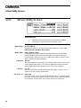
Default Utility Screen
6.0
Default Utility Screen
Quick Reference
Backlight
1
Press the parameter wheel to move between utilities.
2
Turn the parameter wheel to adjust the value.
Dim,Low,Mid,High
This utility adjusts the brightness of the screen backlight
View angle
This utility adjusts the viewing angle of the lcd display.
Midi Chan
1 to 16
This sets the Midi channel to which the unit sends and responds. Meteorology
transmission and reception is not affected by Midi channel.
Midi XMit
Nil, Met, Prog, Thru
This sets which data is output from the FDS-388 Midi out socket - the Midi thru
socket is hard-wired to the Midi input as normal practice.
Lock Mode
22
Nil
No data is output.
Prog
Program change messages are output on the current Midi channel. Temperature and humidity messages are output on all channels.
Met
Temperature and humidity messages are output on all
channels.
Thru
Thru outputs all input data mixed with any dump data requested
by an external controller. This mode is intended for use in a loop
of units controlled by a master Midi controller.
OEM, Off, On, Owner
OFF
With Lock Mode off, all values can be adjusted unless they have
been locked by the OEM system designer. See OEM below and
Section 19.0, System Security.
ON
With Lock Mode on, only the mutes and gain trims are available
to adjust. The user can step through the edit screens but not
change anything except the display angle and brightness. Left and
right channels cannot be unlinked or linked but the user can look
at each channel in turn. The Default screen displays the current
logo with Lock ON.
OEM
When Lock Mode is set to OEM, the unit will prompt for a four
letter password which must match the password set by the OEM
Default Utility Screen
system designer. If the password is entered correctly, the middle
soft key will allow the user to enter the OEM Hide Screen. If the
password is incorrect, the Lock Mode returns to off. If the user
wishes to create a new program and lock areas using OEM hide
then they should begin by recalling the default program (program
0) or another program which is not OEM locked. All OEM programs are denoted on the Recall Screen with a diamond next to
their name. Programs which have not been used as OEM programs before (e.g. after recalling the default program) can be set
to OEM by entering the password 'BSS' when prompted. Refer to
Section 19.0, System Security.
OWNER
Power Up
Audio In
Sample Rate
Top Soft Key
MIDI DUMP
Middle Soft Key
OEM HIDE
OWNER mode allows the owner of the unit to program a system
and then lock the unit against being reset. With Owner lock ON,
files cannot be deleted, the default program cannot be recalled
and limiters cannot be adjusted. To enter Owner mode, turn the
encoder fully clockwise on the Owner Lock box. To change
Owner mode, the user must enter the current password. In a new
unit the password is 'OMNI'. If turning Owner mode ON, the
user can enter a new password once the old password has been
accepted. There is no way to turn Owner mode off if the password has been forgotten! Refer to Section 19.0, System Security.
Mute, 5s to 60s
This utility allows the user to adjust the time between powering up the unit and
the outputs being returned to the mute status that was set prior to the unit last
being switched off. If the value is set to Mute, the unit will always stay in mute
after powering up.
Anlg, AES
When an AES3 input/output board is fitted, this option selects between analog
input or AES3 input. Please refer to Appendix C.4.
44.1, 48
When an AES3 input/output board is fitted, this option selects the sampling
frequency to be either 48kHz or 44.1kHz. Please refer to Appendix C.4.
MIDI DUMP is intended for use in transferring all the data from one FDS-388
to another. The sending FDS-388 should be connected to the receiving FDS388 with a midi cable. Press theTop Soft Key to initiate the transfer. The
receiving FDS-388 will display the question "Receive dump and overwrite all?"
Select YES on the receiving unit first. The sending FDS-388 will display the
question 'Chan n dump. Receiver ready?" where n is the current midi channel.
Select YES on the sending unit to start the dump.
OEM HIDE is only visible once a password has been entered after setting Lock
Mode to OEM. The OEM Hide screen allows system designers to lock details of
a system setup against being adjusted or viewed by unauthorised users. Refer
to Section 19.0, System Security.
23
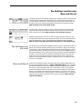
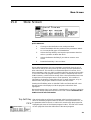
Delay Screen
7.0
Delay Screen
Soft key titles
Main delay
Listening position
Delay units
Band names
Band delay representations
Main delay reference line
Phase adjust
Band polarity
Band delays
Quick Reference
1
To adjust the overall delay for all four bands press the top
soft key and turn the parameter wheel
2
To adjust the delay for an individual band press the middle
soft key, press the encoder to select a band and turn the
parameter wheel to adjust the delay.
3
To adjust a phase or polarity value press the bottom soft
key, press the encoder to select a value to adjust and turn
the parameter wheel to adjust.
The delay screen gives the user access to the various parameters used for time
and phase adjusting the four output bands. The delays of the four bands can be
adjusted in one of three ways.
1 Individually - as would be used for time adjusting single speakers within a
cabinet.
2 In groups - for example, three output bands used to drive three speakers
within a single cabinet.
3 All four bands delayed together - as for a delay tower.
The ear to the left of the screen represents the listener, the line a little to the
right of the ear represents the overall delay of the unit. This line does not,
however, move as the overall delay changes, it is there purely to show the
individual band delays more clearly. If an individual band delay is set to zero
that band’s speaker icon will be positioned on the reference line. As the band’s
delay is increased, the icon will move away from the reference line and shift
toward the right - representing an increased ‘distance’ from the listener’s ear.
No scaling is intended between the pixels on the screen and the delays
represented; the speaker icons will automatically scale their positions to show
the relative delays between bands as clearly as possible.
24
The band names to the right of the band delay values are for reference only.
The names can be changed by the user in the ‘More Crossover’ screen. Refer
to Section 13.0 XOver More Screen.
Delay Screen
Top Soft Key
MAIN DELAY
Selecting the top soft key allows the user to adjust the overall delay of all four
outputs. Alongside the Main Delay value are the units used to display both the
Main and Band Delay values. The units can be changed in the Delay Utility
screen.
Refer to Section 8.0, Delay Utility Screen - Delay Units.
Middle Soft Key
BAND DELAY
Selecting the middle soft key allows the user to adjust a single band delay. Use
the parameter wheel push to step between the band delays, then turn the
parameter wheel to adjust the band delay.
Delays can be grouped together using the Delay Link utility in the Delay Utility
screen. Refer to Section 8.0 Delay Utility Screen - Delay Link. This allows the
user to link band delays that are used in a single cabinet. For example, if the
Delay Link is set up as ABC then the lower three delays will change together,
preserving any offsets previously set between the three delay values.If any
member of the link is selected then the speaker icons for ALL the members of
the group will be shown highlighted. If any of the delays reaches zero or the
maximum delay allowable (approximately 635milliseconds at 20°C, 68F) then
the three delay values will not adjust any further in that direction.
Bottom Soft Key
POL & PHASE
Selecting the bottom soft key allows the user to adjust the Polarity for each
band and the Phase adjustment at each crossover point if a filter has been
assigned to Phase for that band.
Polarity is selectable as either non-inverting ‘+’ or inverting ‘–’ and can be
applied individually to each band.
Phase, if selected, is adjustable from zero to 180°. The phase angle selected is
applied to the lower band of each crossover pair and is the phase adjustment
applied to the lower band output at the crossover frequency. Phase is turned
on and off in the EQ Utils screen and uses one of the two filters available for
each band. Refer to section 10.0 EQ Utility Screen, Filter Mode.
For a complete description of Temperature and Humidity correction Refer to
Section 8.0 Delay Utility Screen.
25
Delay Utility Screen
8.0
Delay Utility Screen
Quick Reference
Press the parameter wheel to move between utilities.
2
Turn the parameter wheel to adjust the value.
Delay Units
ms, ft, m
This selects the units used for displaying and adjusting both main and band
delays on the Delay Screen. ‘ms’ represents milliseconds, ‘ft’ represents feet
(and, for short delays, feet and inches) and ‘m’ represents metres. Note that for
longer delays, the resolution of the parameter wheel is reduced to match the
number of decimal places displayed. Short delays will adjust in approximately
10us increments whilst longer delays will adjust in 100us increments.
Delay Link
AB, BC, CD, ABC, BCD, AB-CD
Delay Link allows the user to link delay values to create ‘cabinets’ of related
delays; for example, if three output bands are used in a single speaker pack.
First adjust the internal delays within the group of bands to line up the speakers
within the pack while Delay Link is set to OFF. Then move back to Delay Link
and set it to ABC or BCD depending on the block of channels to link. Adjusting
any of the three delays in the pack will now change all three, preserving the
time settings within the pack. Note that only adjacent bands can be linked and
that the setting ‘AB-CD’ allows the top and bottom bands to be linked as two
independent pairs. If you want to link all four bands together just use the main
delay!
Temp
Delay Corrn
26
1
Adjustable –20 to +50°°C (–4 to +122°°F)
This is the current temperature used to correct delay times and absorbtion
ensuring that delay distances and frequency response stay constant with
changes in temperature. Delay correction is turned on and off using Delay
Corrn below.
Off, On
This item changes the delay temperature correction mode.
Off
Temperature correction is off and delays will not change with
temperature even if a meteorology probe is plugged in. Delays set
with Delay Corrn off are assumed to have been set at 20°C (68F).
On
Temperature correction is adjusted using the value set by the user
or the meteorology probe in Temp above. The Meteorology
utility, below, sets whether the temperature value comes from the
user entering a value or from the meteorology probe. As the
temperature value changes, the output delays will change to keep
the effective delay distances constant.
Delay Utility Screen
Note that changing this parameter can cause delay times to shift slightly. If
temperature correction is to be used the temperature probe should be plugged
in and this mode set to On at the time that the delays are set up.
Humidity
Adjustable 0 to 100%
This is the current percent relative humidity used to correct the high frequency
response of a system as the relative humidity of the surroundings change. Refer
to Section 20.0, Meteorology for more details.
Absorb Corrn
On, Off
This variable turns high frequency absorption correction on and off. This is
used in conjunction with Meteorology below. Refer to Section 20.0, Meteorology for more details.
Corrn Dist
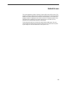
Meteorology
Adjustable 0 to 50metres
This variable sets the distance at which the absorption correction is calculated
and should be set to the average distance of the listeners from the speakers.
Refer to Section 20.0, Meteorology for more details.
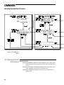
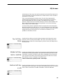
Man, Auto, Midi
This variable selects from where the control for the absorption and temperature
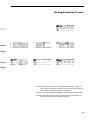
correction is taken. The figure below shows the settings when using meteorology with several FDS-388s, both with and without an FPC-900 remote.
FDS-388s without
FPC-900 remote
FDS-388s with FPC-900
remote
27
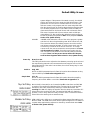
EQ Screen
9.0
EQ Screen
Frequency
Filter band and number
Band name
Swap status
Program number
Bandwidth or
Cursor
shelf shape Cut/boost
Filter marker
OEM name
Edited flag
Combined EQ and
crossover curve
Program name
Full bandwidth curve
Quick Reference
1
Press the parameter wheel to select a filter to adjust.
2
Press the top soft key and turn the parameter wheel to
adjust the filter frequency.
3
Press the middle soft key and turn the parameter wheel to
adjust the filter bandwidth.
4
Press the bottom soft key and turn the parameter wheel to
adjust the filter cut or boost.
Each band of the FDS-388 has up to two parametric filters. Each filter is adjustable for frequency, width and cut/boost in exactly the same way as those in the
FCS-926 and FCS-920 Varicurve devices. In addition, one filter per channel
(Filter 1) can be made to be dynamically adjustable - changing its cut/boost
value as the signal level changes. The other (Filter 2) is switchable between EQ
or phase angle adjustment using the utility on the EQ Utility Screen. In addition
to the Varicurve style ‘bell’ filters, each filter can be selected to be either high
shelving or low shelving with cut or boost available at either end and adjustable slope of 6dB or 12dB per octave.
At the top left of the screen are the name of the current band and the bandletter
and filter number of the current filter. The filter is referred to in the form A1 or
C2 etc. where A or C is the band letter and 1 or 2 indicates which of the band's
filters are currently selected. If one of the filters is selected to be used for phase
adjustment then only filter 1 is available for equalisation. Similarly, to avoid
conflict with the phase function, only filter 1 in one of the band's can be
selected to be a dynamic filter. Refer to Section 10.0, Eq Utility - Filter Mode
& Dynamic Filter.
In the centre of the top row is the current program number, a letter denoting
which backup/swap memory is being used and an asterisk to indicate when the
current program has been edited. To the right are the OEM name and the
current program name.
28
EQ Screen
At the bottom of the screen the small arrowheads indicate the filter frequencies
in the current band. A solid arrowhead and a dotted vertical cursor are used to
represent the current filter.
Two curves are displayed on the Eq screen. The solid line represents the
resultant response of the filters in the currently selected band as if the band
were full bandwidth from 15Hz to 20kHz. The dotted line is the actual
frequency response of the current band with the crossover rolloffs added to the
filter curves. This allows the user to see equalisation curves even when they
have no effect in the current output.
To select a filter press the parameter wheel. Each press will move through the
filters in the order A1, A2, B1, B2, C1, C2, D1, D2 and back to A1. If any filters
have been taken for phase adjustment or have been hidden by the OEM system
designer then they will be missed out. If no filters are available, it is not
possible to enter the EQ Screen.
Top Soft Key
FR/Hz
Middle Soft Key
W/Oct (SLOPE)
Pressing the top Soft key and turning the parameter wheel adjusts the centre
frequency of the currently selected filter. The value in the soft key box is the
filter frequency in Hertz; the centre frequency for bell curves, the 3dB point for
shelving curves.
Pressing the Middle Soft key and turning the parameter wheel adjusts the band
width of the currently selected filter. The value in the soft key box is the width
of the filter in octaves. The width of each filter is adjustable from 0.05octaves
up to 3octaves. If the filter is set to shelving, this box allows the user to select
either 6dB per octave or 12dB per octave filter slopes.
Refer to section 10.0, Eq Utility Screen - Filter Shape
Bottom Soft Key
+/–dB
Pressing the Bottom Soft key and turning the parameter wheel adjusts the cut or
boost value of the current filter. The value in the soft key box is the cut or boost
value in dBs. A maximum of ±15dB is available in each FDS-388 filter.
29
EQ Utility Screen
10.0
EQ Utility Screen
Filter Shape
Low, Bell, High
Each of the available filters in each band can be selected to be low shelving,
bell or high shelving. This selection always applies to the currently selected
filter in the Eq Screen. The current band name and the band letter and filter
number are shown next to this variable for reference.
Filter Mode
Norm, Phase
Filter Mode selects whether or not the user wishes to use one filter per band for
phase correction. With this value set to Normal, two filters are available for
equalisation in each band. With it set to Phase, one is stolen and used in the
Delay Screen to adjust the phase correction at each crossover point. Refer to
section 7.0, Delay Screen. Note that it is always filter 2 in each band that is
taken for phase adjustment. Each band is adjustable individually and it is the
current band's value of Phase/Normal that is adjusted here.
Dynamic Filter
Off, A1, B1, C1, D1
This selection is used to select one filter per side to act dynamically; its cut or
boost are adjusted as the signal level in the band changes. Refer to Dynamic
Filter on the next page.
Dyn Thresh
Adjustable -20dB to -2dB
The value determines the threshold below which the dynamic filter operates.
The value is in dB relative to the band limiter threshold. Refer to Dynamic
Filter on the next page.
Dyn Link
30
On, Off
With Dynamic Link on, the control signals for the left and right dynamic filters
are combined to prevent differences between them causing stereo shifting
effects. With this value off, the two sides work independently. Refer to
Dynamic Filter on the next page.
EQ Utility Screen
10.1 Dynamic Filter.
The dynamic filter works in one of two distinct ways depending on whether the
filter selected is in boost or cut mode.
In boost As an increasing signal level approaches the dynamic threshold, the boost
value of the filter is progressively reduced until the filter is flat when the signal
level reaches the dynamic threshold.
In cut As an increasing signal level approaches the dynamic threshold, the cut value
of the filter is progressively increased from flat until the filter is at its full cut
value when the signal level reaches the dynamic threshold.
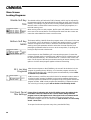
Both functions serve to reduce the filter level as the overall signal level in the
band increases.
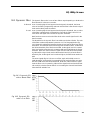
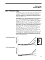
The threshold for the dynamic filter is set relative to the band limiter. The ratio
of the filter cut/boost adjustment is preset to 2:1. The first graph below (fig
10.1) shows the relationship between the signal level and the filter level with a
boost filter. The example shown has the dynamic threshold set to -10dB below
the limiter threshold and a filter boost of 6dB. As the signal level is increased
from low levels the filter boost is constant at 6dB until 22dB below the limiter
threshold. With each 2dB increase in signal level the filter boost is decreased
by 1dB until the signal level reaches the threshold at which point the filter is
effectively flat. As the signal level continues higher, the filter boost remains at
0dB.
The second graph (fig 10.2) shows a cut filter, again with a 6dB cut and a 10dB threshold. As the signal is increased from low levels the filter now stays
flat until 22dB below the limiter threshold. With each 2dB increase in signal
level the filter cut is increased by 1dB until the signal level reaches the threshold at which point the filter at 6dB of cut. Increasing the channel level further
holds the filter at 6dB of cut.
Fig 10.1 Dynamic EQ
with a Boost Filter
Fig 10.2 Dynamic EQ
with a Cut Filter
31
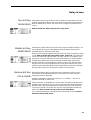
XOver Screen
11.0
XOver Screen
Master rolloff slope
Master rolloff shape
Swap status
OEM name
Program number
Edited flag
Program name
Crossover frequency
Band gain
Limiter threshold
Band edges
Band name
Quick Reference
1
To adjust a band gain value, press the top soft key, press
the parameter wheel to select a band and turn the parameter wheel to adjust.
2
To adjust the limiter threshold for an individual band press
the middle soft key, press the parameter wheel to select a
band and turn the parameter wheel to adjust the threshold.
3
To adjust a crossover frequency, press the bottom soft key,
press the parameter wheel to select a crossover point to
adjust and turn the parameter wheel to move it.
The XOver (Crossover) Screen gives the user access to the top level of crossover frequency adjustment in addition to control of the band gain and limiters.
The left hand end of the top line of the screen gives the master band edge rolloff in dB per octave and the edge shape; whether it is Linkwitz-Riley (L-R),
Butterworth (But), or Bessel (Bes). The centre of the top line contains the
current program number, a letter denoting which backup/swap memory is
being used and an asterisk indicating when the program has been edited. To
the right of the top line are the current program OEM name and user name.
The band names in the horizontal line between the gain and limiter threshold
values are for identification only and can be adjusted in the XOver More
Screen, refer to Section 13.0, XOver More Screen - Name
32
XOver Screen
Top Soft Key
Gain/dB
Middle Soft Key
Limit/dBu (or mV)
These gain values are intended to be used for system set up, the front panel
gain trim controls being used for fine tuning. The XOver screen gain
adjustments give an overall control of ±15dB relative to the channel input.
Note that limiter thresholds refer to levels at the outputs and are not affected by
the gain settings. The front panel gain trims give an additional ±6dB of
adjustment. Note that when storing programs that the front panel gain trims
will be added into the internal gains to prevent the accidental loss of the
external gain trim information unless the Store Trims function is turned Off.
Refer to Section 14.0, Store and Recall.
These limiter values should be used in conjunction with the input sensitivity
specification for the amplifiers attached to the band outputs. A suggested value
might be 1dB below the amplifier sensitivity value. The FDS-388 limiters have
an infinite compression slope above the user preset threshold value with attack
times automatically linked to the lower band edge frequencies of their related
band. The units for the threshold display are set in the XOver Utility Screen
and are selectable dBu or mV. Refer to Section 12.0, XOver Utility Screen Limit Units.
Note that the output level meters display a value relative to the band limiter
threshold. dB values on the meters are dB below threshold, the 0dB led being
at the onset of limiting. Refer to Section 3.1, Output Section.
Pressing the encoder will first step through the limiter values and then through
the limiter on/off flags. Each on/off is represented by brackets around the
limiter value. When the brackets are NOT visible, the limiter is ON for that
band. When the brackets are visible, the limiter is OFF for that band but the
meter is still referenced to the limiter threshold. This means that limiter
thresholds can be set up with the limiter off and with the meters still correctly
referenced. If a band has the limiter turned off, the OVER led will be lit
continuously as a warning to the user.
Bottom Soft Key
FR/Hz (Crossover
Frequency)
This section allows a fast but basic adjustment of band crossover frequencies.
The user can select between the three band crossover frequencies (the
crossover of the high edge of band A and the low edge of band B for
example), the low edge of band A or the high edge of band D. The crossover
point frequency displayed is the average of the adjacent high and low edge
frequencies. The outer edge frequencies can be set to OUT at their extreme
high and low settings. Note: Each crossover point can be moved throughout
the audio band, no checking is made for a band low edge being set above the
band high edge thereby muting the band output, nor can the FDS-388 know
the frequency capabilities of individual speakers in any system - crossover
edges should be moved with care.
The relative heights of the four bands do not represent any level information the bands are set at slightly different heights to aid the user in identifying the
different bands when edge frequencies overlap. Similarly the edges of each
band are only an approximation of the true edge shape. The user should refer
to the Default Screen for a truer representation of the effect of band edges and
band equalisation.
33
XOver Utility Screen
12.0
XOver Utility Screen
Quick Reference
Press the parameter wheel to move between utilities.
2
Turn the parameter wheel to adjust the value.
Master Slope
24, 18, 12dB/Oct
Changing this value will change the band edge slopes for all band edges.
Refer to Section 13.0 XOver More Screen
Master Shape
Bessel, Butterw, L-Riley
Changing this value will change the band edge shapes for all band edges
between Bessel, Butterworth and Linkwitz-Riley. It should be noted that
Linkwitz-Riley is specified to be 12 or 24dB/Oct although this unit will allow
users access to this shape at 18dB/Oct.
Limit Units
Mono Lo
Lim A, B, C, D
34
1
dBu, mV
This item changes the units used for the limiter threshold values on the XOver
Screen between dBu and mV. The selection enables the user to more easily
match limiter thresholds to the specification of the driven amplifiers.
On, Off
Mono Lo sums the two A band outputs of the FDS-388 to produce a mono
output, such as for a mono sub-bass feed.
Norm, Fast
Each band limiter can be set to fst or normal attack time. The default setting
is normal. The fast setting provides better driver protection especially against
over-excursion, but the sound of the limiter may be less transparent.
XOver Utility Screen
Top Soft Key
Pressing the top soft key in the XOver Utility Screen will take the user to the
XOver More screen. See next Section 13.0, XOver More Screen.
XOver More
35
XOver More Screen
13.0
XOver More Screen
Current edge
Current band name
Swap status
OEM name
Program number
Edited flag
Program name
Band edge frequency
Band edge high slope
Band edges
Band edge low slope
Quick Reference
1
To change a band name, press the top soft key, press the
parameter wheel to select a band and turn the parameter wheel to adjust.
2
To adjust an individual edge slope, press the middle soft
key, press the parameter wheel to select a band and turn
the parameter wheel to adjust the slope.
3
To adjust a band edge frequency, press the bottom soft
key, press the parameter wheel to select an edge to
adjust and turn the parameter wheel to move it.
The XOver More Screen gives the user access to the low level adjustment of
individual edge slopes and frequencies. It also contains the selection of names
for each band.
To the left of the top line are the band name of the currently selected band and
the band letter and whether the edge being edited is high or low.
The centre of the top line contains the current program number, a letter
denoting which backup/swap memory is being used and an asterisk indicating
when the program has been edited. To the right of the top line are the current
program OEM name and program name.
36
XOver More Screen
Top Soft Key
NAME
Middle Soft Key
EDGE SLOPE
Bottom Soft Key
FR/Hz (Edge
Frequency)
Each band can be named from a preset selection. The list includes basic names
such as 'Band A', 'Band B' etc and also band descriptions such as 'Low' and
'Lo Mid'.
These values set individual edge slopes for each band edge. Slopes are
selectable between 12, 18 and 24dB per octave. Note that Linkwitz-Riley
crossovers are specified as 12 or 24dB per octave although the FDS-388 will
allow similar edge shapes with 18dB per octave.
Selecting the bottom soft key allows the user to adjust the frequency of each
band edge individually. In this way, two bands can be made to crossover at a
different level to that of the defaults which are:
Linkwitz-Riley
-6dB crossover
Bessel and Butterworth
-3dB crossover
Alternatively two bands could be made to overlap, both bands passing the
same frequencies. e.g. Low and Low Mid bands could both have the same low
frequency edge.
This section allows the user to spread two or three bands out to form two or
three way crossovers. If the edges of a band are set to 'Out' at both high and
low ends the result is a full range output with a delay set in the Delay Screen.
37
Store and Recall in the Default Screen
Store and Recall in the Edit Screens
14.0
Store and Recall
14.1 Store and
Recall in the
Default Screen
There are two modes of operation for the STORE and RECALL Keys, depending
on whether the unit is in the EDIT mode, as shown by any of the blue LEDs
being illuminated. When in the default mode with no blue LEDs illuminated,
the STORE and RECALL Keys initiate the storage and naming or retrieval of
previously created set-ups or programs, using either the internal memory, or a
PCMCIA memory card. An internal program is recalled by pressing the RECALL
Key, then turning the parameter wheel to select the program and pressing the
RECALL Key again. The current parameters are stored to internal memory by
pressing the STORE Key, turning the parameter wheel to select the program
and pressing the STORE Key again. The user may also be invited to lock the
program. Parameters are stored and recalled for both channels, regardless of
the setting of the SPLIT LEDs.
All the current parameters related to the audio path are saved in the program,
such as crossover frequencies, levels, limit thresholds, equaliser parameters
and delay distances. Certain global parameters such as MIDI channel,
temperature and display brightness etc. are not stored in individual programs,
but are retained separately in the internal memory.
14.2 Store and
Recall in an Edit
Screen
When the unit is in the EDIT mode, as indicated by one of the blue LEDs being
illuminated, the STORE and RECALL Keys are used for the A:B compare
function.
Pressing BACKUP (STORE) puts the current parameters in the backup memory
for later comparison. Pressing SWAP (RECALL) swaps the current parameters
with the backup parameters so that they may be compared both visually and
audibly.
Movement of any of the TRIM controls will cause an equal and opposite
change in the backup memory so that any subsequent swap will leave the
swapped program at the original levels despite the new TRIM settings.
38
Store Screen
15.0
Store Screen
Quick Reference
1
Change to the Default screen and press Store
2
Select the Middle Soft key and turn the parameter wheel
to choose the file type and destination
3
Select the Top Soft Key and turn the parameter wheel to
select a position to Store the file in.
4
Select the Bottom Soft Key if you wish to enter a new
name
5
Press the Store Key a second time.
When editing parameters, the new parameters are retained when the unit is
switched off, and the unit will power-up with exactly the same parameters as
when switched off. This should be considered bad practice however, since
these parameters could very easily be edited unless they are stored away safely
in one of the internal 60 program memory locations, and perhaps also onto a
PCMCIA memory card for archive storage. If the current parameters have been
changed since the last program store or recall operation, this condition is
indicated by the program number being shown in small characters, or by an
asterisk next to the program number in some of the edit screens.
Pressing the STORE Key when no blue EDIT LEDs are illuminated will cause
the store screen to be displayed, with the program number PICK item
highlighted.
Because the startup logo is now stored in internal memory, the logo is stored to
the card for backup purposes whenever an ALL file is saved. See Section 18.0
PCMCIA Card for more information.
Top Soft Key
PICK
After selecting the top soft key the parameter wheel may then be turned to
select an alternative program number to store the current parameters into. As
the parameter wheel is turned, an outline will move through the program list,
highlighting the name of the selected program location. The first row of names
on each page also shows the OEM name of the stored programs.
39
Store Screen
Locking Programs
Middle Soft Key
TYPE
The middle soft key will select the TYPE of storage, which may be adjusted by
the parameter wheel from the default INTernal setting to either of the PCMCIA
memory card settings; CPrg to store the current program parameters, or CAll to
store the entire contents of the internal memory, including all programs, to a
PCMCIA memory card.
When storing a file to a card program, the file name will default to the current
user name. If the user wishes to use a different file name from the current user
name then select NAME and enter a card file name.
Bottom Soft Key
NAME
The bottom soft key, NAME, allows the program name, or file name in the case
of a PCMCIA card, to be entered or changed. After pressing this key, a naming
window will appear on the screen in which the user builds up the required
word by turning the parameter wheel to select the character required, and
pressing the parameter wheel to move on to the next position, or pushing and
turning to skip forwards or backwards.
A second press on the STORE Key will now store the program. If a name has
not been selected and the current file type is INTernal, then a default name will
be allocated automatically. The default name for a card file is the current user
name. The final part of the store process when storing to internal memory is the
option to lock the saved program against accidental overwriting.
15.1 Locking
Programs
After the second press on the STORE Key, the user will be invited to lock the
program by pressing the top YES Key, or to leave the program unlocked by
pressing the bottom NO Key. OEM programs are automatically locked. Refer
to Section 18.0, OEM Hide.
PCMCIA memory card files cannot be locked. If an attempt is made to store to
a locked location, storage is inhibited, and a warning message is displayed.
Locked programs are identified in the program list by a key symbol next to the
program number. OEM locked programs are identified by a diamond symbol.
For unlocking a locked program refer to Section 17.0 File Utility Screen.
15.2 Front Panel
Trim Settings
If Store Trims is selected to ON in the File Utility Screen, the settings of the
level TRIM controls are added to the crossover LEVEL settings when the
program is stored, although the level of the signal chain is not altered at this
point. If the program is recalled with Store Trims turned ON the user is
prompted to set gain trims to zero after recall. Refer to Section 17.0 File Utility
Screen - Store Trims.
To escape from the store process at any time, press the EDIT Key.
40
Recall Screen
16.0
Recall Screen
Pressing the RECALL button when no blue EDIT LEDs are illuminated will
cause the recall screen to be displayed, with the program number PICK item
highlighted.
Top Soft Key
PICK
Middle Soft Key
TYPE
The parameter wheel may then be turned to select an alternative program
number from which to recall the new parameters. As the parameter wheel is
turned, a highlight bar will move through the program list, highlighting the
name of the selected program location. The first row of names on each page
also shows the OEM name of the stored programs.
The middle soft button will select the TYPE of program or file, which may be
adjusted by the parameter wheel from the default INTernal setting to either of
the PCMCIA memory card settings; CPrg to recall a single program, or CAll to
set the entire contents of the internal memory to a new set-up, including all
programs, from a PCMCIA memory card.
A second press on the RECALL button will now set the current parameters to
that of the program. If an attempt is made to recall from a blank location,
recall is inhibited, and a warning message is displayed. If any of the level TRIM
controls are non-zero, the user will be invited to centralise them.
To escape from the recall process at any time, press the EDIT button.
41
File Utility Screen
17.0
File Utility Screen
Program Lock
Store Trims
Top Soft Key
FORMAT CARD
On, Off
Changing this value will change the Program Lock status of the currently
selected Internal program.
On, Off
With Store Trims On, storing a program will add the gain trim values into the
internal gain values, ensuring that any gain trims are not lost when programs
are later recalled. This also means that gain trims must always be set to zero
when recalling programs stored in this way to prevent gain errors building up.
Alternatively, Store Trims Off will not include the gain trim values when
programs are stored.
Pressing the Top Soft Key will ask if the user wishes to lose all data on the
Smart Card. If the user then presses the Top Soft Key again the card in the card
slot will be cleared and formatted ready for use.
Flash cards cannot be incrementally written to and may only be used to store a
CAll file. A CAll file will automatically be written to the Flash card when it is
formatted.
Bottom Soft Key
DELETE FILE
42
Pressing the Bottom Soft Key will delete the currently selected file whether it is
an internal program or a card file. The screen will prompt the user whether
they really wish to delete the file. Press the Top Soft Key to delete. Delete File
is not available when Owner Lock is on. Refer to Section 18.0, System
Security.
PCMCIA Card
Card Types
Smart Card Format
18.0
PCMCIA Card
The Smart Card socket on the front of the unit is designed to use PCMCIA2
memory cards of between 128kbyte and 2Mbyte storage capacity. Files are
stored on the card in a ‘Pseudo-floppy’ format using standard DOS structures.
See the box at the end of this section for compatibility information. As existing
Flash memory cards have erase and re-write limitations, only SRAM memory
cards are fully supported in the current Smart card software. The exception is
that a full set-up (an XAL file) is stored to a Flash card when it is formatted .
The Flash card set-up can then be read at any time, but only written to by
performing a complete format again. This is useful for archive purposes as
Flash cards have no batteries to run down. The FDS-388 has been tested using
Fujitsu 256k FLASH cards.
Formatting a FLASH card will also write an XAL file to the card. If a FLASH
card is detected when a FORMAT is STARTed, the card is formatted as usual
and then a single XAL file is written to the card using the current unit data. No
further SAVE operations can be performed on a FLASH card although the saved
XAL file can be LOADed at any time.
NOTE: Flash cards should be the older Series 1 Flash cards. Newer Series 2 Flash
cards may not work.
18.1 Card Types
The Smart Card interface requires 68pin PCMCIA2 compatible memory cards.
Attribute memory is not required and is not used. The most appropriate card
size for the FDS-388 is the 256k byte card which can hold up to 14 complete
setup (XAL) files.
SRAM CARDS
128k, 256k, 512k, 1M, 2M. Battery life varies with manufacturer and memory
size and should be checked with the card supplier. Expect 4 years or more
from a 256k card or around a year with 1Mbyte and above.
Cards are now becoming available from manufacturers such as Centennial that
are rechargable. These cards should periodically be left in the card slot of an
FDS-388 for a few hours to recharge. Expected battery life for rechargable
cards when not plugged into a unit is expected to be around one year; this
should be checked with the card supplier.
FLASH CARDS
256k, 512k, 1M, 2M. All FLASH cards are formatted as 256k with a single
ALLDATA file recorded on them. The FDS-388 has been tested using Series 1
flash cards: e.g. Centennial FL256-20-1XXXX-XX.
18.2 Smart Card
Format
The Smart Card filing system on the FDS-388 uses a ‘pseudo-floppy’ format.
Formatting a Card on the FDS-388 writes a standard PC DOS format to the
card beginning at byte 0 as if it were the first byte on a disc. The format writes
a DOS boot sector with basic format data but does not write boot software.
This is followed by a single File Allocation Table (FAT) starting at byte 200H.
The root directory is written with one entry, a sub-directory called BSSDATA.
All data files used by the remote are stored in the BSSDATA sub-directory as
there are limits to the number of files that can be stored in the root directory.
43
PCMCIA Card
The different file types used by the unit have different file extensions as follows.
The file sizes should be taken as approximate and may change with new
versions of software.
Program
All data
Logo
*.XPG
*.XAL
*.XLO
273bytes
16616bytes
1921bytes
The ‘pseudo-floppy’ filing system as used on the unit conforms to the PCMCIA
PC CARD standard although it does not format Card Information Structure (CIS)
information. BSS has tested and developed the Card filing system using an IBM
compatible PC card reader and a range of palm-top computers, but cannot
guarantee that the cards can be read by any particular piece of computer
equipment. To be able to transfer files to and from an external computer note
the following:
$ Always format the card on the external computer.
% Always write a sub-directory called BSSDATA into the root directory
straight after formatting the card. All files used by the FDS-388 and FPC-900
remote are stored in the BSSDATA sub directory.
44
System Security
Program Lock
Lock Mode
19.0
System Security
Any changes made to an audio system have the potential to be damaging, even
if only accidentally made. For this reason several different security systems are
built in to the FDS-388 to protect the speakers.
Each of the security levels locks different groups of variables away from
adjustment.
19.1 Program Lock
This is a flag that is available for each stored program. A program can be
locked when it is stored - the user is prompted when Store is pressed the
second time. Alternatively, the program can be locked or unlocked later using
the Program Lock entry in the File Utility Screen. Refer to Section 17.0, File
Utility Screen.
Locking a program in this way is purely to protect the user against
accidentally overwriting a stored file. The lock status can be changed by
anyone unless the program is OEM locked (see next page).
19.2 Lock Mode On
The Lock Mode entry in the Default Utility Screen can be set to one of four
options, On, Off, OEM and Owner. Owner and OEM are covered below.
When Lock Mode is set to ON, no variables can be changed expect for the
Display Angle and Backlight and, of course, the Lock Mode. The user can
move around the screens to look at any variable but only the front panel gain
trims and mutes are available to be adjusted. When Lock Mode is ON, the
Default Screen will display the unit's logo along with the current program
number and names. Refer to Section 6.0, Default Utility Screen - Lock Mode.
Locking the unit in this way is only to protect the user against other users
changing the system setup accidentally or against unauthorised people
intentionally changing the system. This status can be changed by anyone who
knows the FDS-388.
19.3 OWNER Lock
Owner Lock is turned ON and OFF using the Lock Mode variable in the
Default Utility Screen. Refer to Section 6.0, Default Utility Screen - Lock
Mode. To turn Owner Lock ON the user will be asked to enter the current
password and then be allowed to change the password to a new, different
password if required. To turn Owner Lock OFF, the current password must be
entered. The password in a brand new unit will be 'OMNI '.
The Owner in this case is the person or company who has set up a system and
wishes to allow the day-to-day operators restricted access to program recall
and adjustment; an example would be a p.a. hire company.
Owner Lock ON has the following effects.
$ The operator cannot recall the Default program and thereby start adjusting
the system from scratch. The operator can still recall any programs that the
owner has left in the unit and overwrite any that are not OEM protected
(see OEM Lock below). For example, if the owner fills all 60 memories with
OEM locked programs the operator can only recall the owner's programs
and cannot overwrite any of them.
45
OEM Lock
Safe
% Files cannot be deleted.
& Limiter thresholds cannot be adjusted.
The operator can still adjust any variables (except the limiter thresholds) and
save the program to an empty program space or over a non-OEM original
program.
Locking the unit is this way is to allow the Owner of the system protection
against operators resetting the FDS-388. This lock mode can only be changed
by people who know the Owner Lock password. Be warned that it is
impossible to unlock a unit where the password has been forgotten.
19.4 OEM Lock
The OEM lock mode gives the user the privilege of being able to hide selected
parameters from other users view and prevent those parameters from being
tampered with. A password is entered by the OEM engineer to protect the
integrity of the locked parameters, and this password is necessary to
subsequently gain access to the OEM locked parameters and to the parameter
locking mechanisms. An OEM name may also be entered to identify the type
of system that the program was designed for. The end user may then use the
locked OEM program as a basis for operating such a system, and make further
modifications to the set-up, to an extent completely controlled by the OEM
designer.
Refer to Section 6.0, Default Utility Screen - Lock Mode. To turn OEM Lock
ON or OFF the user will be asked to enter the current password. Once in the
OEM Hide Screen, the user can change the password. Refer to Section 18.6,
OEM Hide Screen - OEM Passwd. The default password in a new program will
be 'BSS '.
When OEM programs are stored, they are automatically program-locked, and
identified in the program list by a diamond. The OEM program lock status
cannot be undone by the program lock utility, but an OEM program may be
over-written by another OEM program with the same OEM password.
NOTE. To store a program as an OEM program, the unit MUST be in OEM
mode when the program is stored, otherwise the stored program will not be
identified as an OEM program in the program list.
19.5 Safe
The FDS-388 has a hidden function called SAFE. SAFE mode is intended to be
used as a complete lock-out for installations or as the ultimate protection for
hire systems etc. When SAFE mode is switched on, all controls are disabled,
the screen blanks and the backlight adjusted to dim. With SAFE mode ON the
meters still run but no one can change any values within the unit.
The user must be aware that any adjustments made to the gain controls whilst
in Safe will not be heard until Safe is turned off.
As the SAFE mode is intended for security, the details of its use can not be
published here. Please consult your dealer for further information on SAFE
mode.
46
OEM Hide Screen
19.6 OEM Hide
Screen
Quick Reference
1
To change the OEM password press top soft key, press the
parameter wheel to select letter and turn the parameter
wheel to change the letter.
2
To change the OEM name press middle soft key, press the
parameter wheel to select letter and turn the parameter
wheel to change the letter.
3
To change OEM hides, press bottom soft key, select item
to hide by pressing the parameter wheel, and turn the
parameter wheel to toggle the hide status.
The OEM hide screen enables OEM designers to create password protected
programs which allow users limited access to the parameters. Hidden parameters are not visible in their respective edit screen, and therefore not adjustable. The designer may, for example, not wish the user to see eq corrections or
in-box delays that have been used to tune the sound of a system. It is possible
to hide all parameters in some screens such as XOVER and EQ, in which case
the user will not be able to enter these screens. Pressing the Edit key will skip
the screen and go to the next available edit screen. When in OEM lock mode
all parameters are visible whether they are hidden or not, allowing the OEM
system designer freedom to adjust the system at a later date without having to
turn off all the hides.
47
OEM Hide Screen
Top Soft Key
OEM PASSWD
Middle Soft Key
OEM Name
Bottom Soft Key
OEM HIDE
48
The OEM password is used to prevent unauthorised access to this screen, and
must be entered in the default utils before the OEM soft key will be available
Refer to Section 6.0 Default Utility for more details. The default password is
BSS and this will become active the first time the Lock Mode is changed to
OEM. Each letter of the password can be changed by pushing and turning the
encoder to move between the letters and adjust their values respectively. The
letters can be adjusted to any member of the alphabet or space, with the
exception of the first letter which cannot be space (this is to force OEM
designers to password protect their programs).
The OEM name appears at the top of most screens, to denote the originator of
the current program. The letters can be adjusted to any member of the
alphabet, numbers 0-9 and space. This would normally be set to the name or
number of a loudspeaker system.
OEM hidden items are indicated by a key symbol which can be toggled on
and off by turning the encoder, and selected by pressing the encoder.
Meteorology
Humidity Effects
20.0 Meteorology
Temperature and humidity cause dramatic changes in the absorption of sound
in air over a broad frequency range, which can cause inconsistent sound
quality during the course of a performance. The FDS-388, equipped with the
optional meteorology probe, can compensate for these effects. Figures 20.1
and 20.2 show the absorption curves under various humidity and temperature
conditions at a distance of 25m.
The FDS-388 provides absolute compensation. It compensates for conditions as
they differ from lossless air, therefore under all atmospheric conditions some
form of correction will be applied. It is most important, therefore, when
initially setting up the system that correction is set to ON when adjusting the
house EQ. The compensation is always in the form of a 6dB/Oct high shelf
providing various amounts of boost. The actual boost value set is not only
determined by temperature and humidity but is also directly proportional to the
user set distance. The correction distance should be set to the distance of the
average listening position from the speakers. At this position the atmospheric
effects and shelving EQ will cancel each other. The presence of the
meteorology filter in the system will result in different settings for the house
EQ. Once the system is set up, however, as the conditions change the filter
parameters will be adjusted and sound quality will remain constant.
The FDS-388 will also adjust the user set delay times to ensure that the delay
distance is kept constant with temperature changes. As the ambient
temperature changes, the speed of sound in air changes and the delay heard at
a constant distance will change accordingly. With Delay Corrn in the Delay
Utility Screen set to Auto, the FDS-388 will adjust delay times to keep delay
distances constant. Delay Corrn will have to be set to Auto or Manual before
setting the delay times or distances.
6
Relative Humidity
Absorption at 25m (dB)
Fig 20.1 Correction
Curves at 20°C and 25m
5
30%
3
50%
2
70%
1
0
100
100%
Frequency (kHz)
1000
10000
Frequency (kHz)
1000
10000
6
Absorption at 25m (dB)
Fig 20.2 Correction
Curves at 0°C and 25m
10%
4
5
4
3
2
1
0
100
49
FDS-380 Omnidrive Install
FDS-380 Controls
21.0 FDS-380 Omnidrive Install
21.1 FDS-380 A Midi Channel Select Buttons
Controls Pressing either button will display the current midi channel number. Further
presses of the upper button will increment the midi channel number, the lower
button will decrement it.
B
+10dB indicator
This led is lit when the rear panel +10dB switch is on.
C
Safe indicator
This led is lit when the rear panel Safe switch is on.
D
PC Card slot
The FDS-380 can load device files with the name LOADmm.XAL where mm is
the current midi channel number. Refer to Section 21.3 for more details.
E
Display
P 0 1 The display defaults to displaying the current program number.
C 0 1 If the midi channel select buttons are pushed, the display will show the
current midi channel number.
E 0 1 Errors are displayed as an error code. Appendix B contains a complete
list of the FDS-380 error codes and relates them to the standard FDS-388
messages.
F
Midi indicator
This led indicates that the unit is receiving a midi message on its midi channel.
G
Clip indicators
The upper pair of clip leds are driven from the input circuitry and indicate
input overload. The lower pair of clip leds indicates overload at one of several
points through the digital signal path. Overload in the digital section is most
often caused by large eq filter boosts.
H
Audio level leds
The bottom leds of each set indicate the presence of a signal, the upper led
indicates the limit threshold.
50
Midi Operation
PC Card Operation
The FDS-380 can be programmed either through the midi interface or by
using the PC Card:
21.2 Midi
Operation
Data can be transferred between any combinations of FDS-380 and FDS-388
using device data dumps.
The midi channel is set by pressing one of the two buttons at the left hand end
of the front panel using a matchstick or pen top. The first press will display the
current midi channel number, further presses will change the channel number.
The upper button increments the midi channel number, the lower button
decrements it.
Set the midi channel numbers in the destination and source units to be the
same. Prepare the dump from an FDS-380 by pressing both of the midi buttons
at the same time. After pressing the first time the unit will display 'rdy' allowing
the user time to confirm the dump if sending to an FDS-388. To start the dump,
press both of the midi buttons a second time. The FDS-380 will show 'Snd'
whilst sending the dump. If a dump is sent from another FDS-380 or an FDS388 into the FDS-380, the display will show 'rec' whilst receiving.
The unit will also respond to midi program change messages sent to its
channel.
All variables in the unit can be adjusted over midi.
Edited led If a variable in the unit has been edited by changing it's value over midi, the
right hand decimal point in the display will flash.
21.3 PC Card
Operation
Device data can be installed into an FDS-380 Omnidrive from a PC Card. If a
card is inserted with a file called LOADmm.XAL (where mm is the current midi
channel number) that file will be loaded into the unit. For example, a card
could have the files LOAD01.XAL, LOAD02.XAL and LOAD03.XAL stored on
it using an FDS-388. To access file LOAD01.XAL, an FDS-380 must be set to
MIDI channel 1. To access LOAD02.XAL, the FDS-380 must be set to MIDI
channel 2, and so on. The MIDI channel number of the FDS-380 can be
changed by using the MIDI channel select buttons (See opposite).
When a card with the appropriate file is inserted into the unit, the user will
have a three second countdown in which to pull out the card if they realise
that they did not wish the unit to be overwritten or if they did not realise that
the file was on the card.
Ensure that when data is transferred to an FDS-380 either by card or by Midi
NOTE: that the Mutes are not on. The mutes cannot be turned of and on once the
data has been dumped into the FDS-380.
51
!!! CAUTION - Important Notes !!!
SERVICE SECTION
22.0
Service section
22.1 Transient
Suppressor
Replacement
The primary of the mains transformer within the FDS-388 is protected against
high voltage spike interference by two voltage dependent resistors. These
provide a short circuit to voltage peaks in excess of their maximum rating.
Should the FDS-388 be inadvertently connected to 3 phase line/line voltages,
or to 240V when selected to 120V, or any other incorrect voltage, these
suppressors are likely to fail in a protective short circuit mode. This will be
demonstrated by repeated mains fuse failure when powering up the unit.
Figure 22.1 indicates the location and specification for the suppressors.
Figure 22.1 Suppressor
location
!!! WARNING - Refer all servicing to qualified service personnel !!!
Risk of electric shock if the unit is opened.
BSS Audio accepts no responsibility for injury
subsequent to opening of the unit.
52
!!! CAUTION - Important Notes !!!
SERVICE SECTION
22.2 100V Tap
Conversion
A tap change is available on the FDS-388 to allow the unit to work reliably at
mains votages down to 90VAC on the 120V setting and 180VAC on the 240V
setting.
To implement the change proceed as follows:
1 Disconnect mains power and remove the unit's top cover.
2 On the small pcb mounted at the rear of the box on the 120/240V selector
locate the purple and brown wires and reverse their positions. Locate the
orange and yellow wires and reverse their positions. Fuse values do not
change from that required to match the voltage selector. The following
table shows the wire colours referenced to the silk screen labels on the PCB
for both normal and lower voltage applications.
3 Replace the top cover.
WARNING! The maximum mains voltage allowable under these
circumstances is 110VAC for the 120V setting and 220VAC for the 240V
setting
Silk Screen Label
GRN
YEL
BLUE
BRN
PUR
ORG
Cable Colour
Normal Setting
Green
Yellow
Blue
Brown
Purple
Orange
Cable Colour
Low Voltage Setting
Green
Orange
Blue
Purple
Brown
Yellow
!!! WARNING - Refer all servicing to qualified service personnel !!!
Risk of electric shock if the unit is opened.
BSS Audio accepts no responsibility for injury
subsequent to opening of the unit.
53
Warranty Information
23.0
Warranty Information
This unit is warranted by BSS Audio to the original end user purchaser against
defects in workmanship and the materials used in its manufacture for a period
of one year from the date of shipment to the end user.
Faults arising from misuse, unauthorised modifications or accidents are not
covered under this warranty. No other warranty is expressed or implied.
If the unit is faulty it should be sent, in its original packaging, to the supplier
or your local authorised BSS Audio dealer with shipping prepaid.
You should include a statement listing the faults found. The unit’s serial
number must be quoted in all correspondence relating to a claim.
IMPORTANT
We recommend that you record your purchase information here for future
reference.
Dealer Name:
Dealer Address:
Post/Zip Code:
Dealer Phone No.:
Dealer Contact Name:
Invoice/Receipt No.:
Date of Purchase:
Unit Serial Number:
In keeping with our policy of continued improvement, BSS Audio reserves the
right to alter specifications without prior notice.
The Omnidrive was designed and developed by BSS Audio, Hertfordshire,
England.
Phone (+44) (0)1707 660667. Fax (+44) (0)1707 660755.
World Wide Web address: http://www.bss.co.uk
54
Midi Implementation
Appendix A
V1.1
A.1 FDS-388 Midi
Implementation
FUNCTION
6 June 1996
TRANSMITTED
RECOGNISED
REMARKS
1-16
1-16
1-16
1-16
Memorised
MODE
X
X
NOTE NUMBER
X
X
VELOCITY
X
X
AFTER TOUCH
X
X
PITCH BENDER
X
X
CONTROL CHANGE
NRPN LSB 98
NRPN MSB 99
Data LSB 38
Data MSB 6
X
X
X
X
O
O
O
O
PROGRAM CHANGE
True Number
0-59
1-60
0-59
1-60
SYSTEM EXCLUSIVE
Dump Request
Dump Follows
Program follows
Program Request
RTA Request
Message
Meter Request
Meter Follows
Password Follows
X
O
X
O
O
O
X
O
X
O
O
O
O
O
O
O
X
O
SYSTEM COMMON
X
X
SYSTEM REAL TIME
X
X
AUX MESSAGES
X
X
BASIC CHANNEL
Default
Changed
O: Yes
Note 1
X: No
NOTES:
1: Any parameter out of range will be ignored.
55
Specification and Block Diagram
A.2
Specification and Block Diagram
Dynamic Range
Typically >105dB, Analogue Input/Output, unweighted,
22Hz to 22kHz
Frequency Response
±0.25dB, 15Hz-20kHz with filters out
Distortion (THD)
<0.01%, 20Hz-20kHz @+10dBu
Group Delay Distortion
<±5us, 20Hz-20kHz
Maximum Processing Delay
<1.5ms
Inputs
Electronically balanced & floating
(Transformer balanced option)
Input Impedance
10kΩ
Ω
Maximum Input Level
+20dBu, balanced
Outputs
Electronically balanced & floating
(Transformer balanced option)
Maximum Output Level
+20dBu into 600Ω
Channel Separation
>75dB, 20Hz-20kHz
Stereo Tracking
<2degrees, 20Hz-20kHz
Power Supply
AC Mains 50/60Hz, 120V (99V-121V)
or 240V (204V-264V) selectable,
plus internal 100V setting.
Power Consumption
<60VA
Options:
AES/EBU Input Card
AES/EBU Input/Output card
Input/Output balancing transformers
Meteorology Probe
56
FDS-380/FDS-388 Messages
Appendix B
FDS-380/FDS-388 Messages
FDS-380
FDS-388
FDS-380
“---”,
“-1-”,
“-2-”,
“-3-”,
“BAD”,
“C-B”,
“DRM”,
“E03”,
“E04”,
“E05”,
“E06”,
“E07”,
“E08”,
“E09”,
“E10”,
“E12”,
“E13”,
“E16”,
“E17”,
“E25”,
“E26”,
“E27”,
“E28”,
“E30”,
“E31”,
“E32”,
“E33”,
“E34”,
“E35”,
“E36”,
“E38”,
“E39”,
“E41”,
“E46”,
“E52”,
“E54”,
“E55”,
“E56”,
“E57”,
“E58”,
“FLT”,
“FOR”,
“G-0”,
“L-A”,
“L-B”,
“LOC”,
“NO “,
“OFF”,
”Testing”
“ON “,
”1 second to all load”
“RDY”,
”2 seconds to all load”
“REC”,
”3 seconds to all load”
“SND”,
”TEST FAILED”
“SND”,
”Data copied to backup”
“REC”,
”DRAM FAILED - DSPx”
“REC”,
”Program recall x errors fixed”
“YES”,
”Recall failed, file is empty”
”ERROR: MIDI tx buffer full”
”Power Failure, check fuses”
"x Mode errors fixed”
”Assert Failed x"
”Watchdog Failed Task x”
”Left and right have been split”
”Incoming midi dump error”
”Incoming midi error received”
”The password is wrong”
”Password OK, enter new one”
”Bad card”
”Format not recognised -boot” Bad boot block
”Format not recognised -cis” Bad cis block
”Format not recognised” Bad format
”Bad card write”
”No space on card”
”File does not exist”
”File error”
”There is no card”
”The card is write protected”
”DATA directory not found”
”Wrong flash card manufacturer”
”Wrong flash card type”
”Battery Low”
”Default program is owner locked”
”Excessive errors, using defaults”
”Card battery low”
”Midi dump time out”
”Delete failed - owner locked”
”DSP Comms error - recovering”
”MIDI Comms Error”
”All Flat”
”Formatting”
”Set gain trims to zero”
”Listening to backup A”
”Listening to backup B”
”This program is locked”
”File read error”
”Owner lock OFF”
FDS-388
”Owner lock ON”
”Ready to Dump?”
”****Receiving****”
”Sending system variables”
”Sending program x”
”Received system variables OK”
”Received program x OK”
”Completed or Okay”
57
AES3 Input and Input/Output Boards
Fitting The AES3 Input Board
Appendix C AES3 Input and Input/Output Boards
C.1 Fitting The
AES3 Input Board
Parts Supplied
AES3 input board SC5559 (approx 83mm by 180mm).
AES3 PLL board SC5560 (approx 80mm by 65mm).
AES3 rear blanking panel (approx 40mm by 70mm).
M3 by 6mm screw.
M3 nut.
Removing the 1 Unplug the unit from the mains supply.
Analogue Input Board 2 Remove the 8 screws holding the lid on and the 8 screws holding the base on.
3 Unplug the 34 way IDC cable from the analogue input board.
4 Remove the three M3 screws and washers holding the analogue input board
into the unit; two at the front on the heatsink and one at the rear on the right.
5 Remove the four plastite screws fixing the input XLRs in place.
6 Remove the analogue input board and store in a safe place along with two of
the plastite screws.
Plugging in the AES3 1 Insert the AES3 input board into the unit.
Input Board 2 Fix the board with the three or four M3 screws and washers that were re-
moved.
3 Put the rear blanking panel over the single input socket and fix using two of
the XLR plastite screws and the M3 nut and bolt supplied with the AES3 input
board.
4 Refit the 34 way IDC cable into the AES3 input board.
Removing the 1 Put the unit on its side and remove the long M2.5 screw and nut which fix the
small PLL board onto the analogue output board.
Standard PLL Board
2 If there is an earth strap connecting the PLL board to the analogue output
board, unplug it from the large analogue output board.
3 Unplug the small PLL board from the analogue output board. The pins on the
new AES3 PLL board may be protected with a plastic cover or an IC socket. If
so, remove it from the AES3 PLL board and put it onto the pins of the standard
PLL board, removed from the unit, to protect the pins.
Plugging in the AES3 1 Plug the larger AES3 PLL board into the analogue output board. The board
should be plugged in with the main part of the AES3 PLL board pointing
PLL Board
toward the front of the unit. Ensure that the pins go in straight and that all pins
are in the socket. Check that the pin 1 marker on the analogue output board
is at the same end as the pin 1 marker on the top of the AES3 PLL board.
2 Replace the long M2.5 screw and nut through the AES3 PLL board and the
analogue output board.
3 Power up the unit, being careful not to touch any of the mains input circuitry,
and check the input board with either a 44.1kHz AES3 input or a 48kHz
AES3 input; the input will automatically sync to whichever clock frequency is
used. If the clock frequency is changed whilst the unit is on, the output of the
unit will mute for a few seconds while locking to the new frequency.
4 Switch off and replace the unit’s lid and base panels.
58
AES3 Input Board Operation
Fitting The AES Input/Output Board
C.2 AES3 Input
Board Operation
With the AES3 Input board fitted the operation of the Omnidrive unit is largely
unchanged. The dynamic range of the Omnidrive with AES3 input is slightly
better than when an analogue input board is fitted and measures greater than
107dB.
The Sample Rate item in the Default Utilities screen will display the current
AES3 input sample rate as either 44.1kHz or 48kHz. If the AES3 input is
removed or goes out of a narrow lock range, the output relays will immediately
mute the analogue outputs. The output relays will be unmuted when the input
is back within lock range again.
C.3 Fitting The
AES3 Input/Output
Board
Parts Supplied
AES3 input/output board SC5575 (approx 300mm by 180mm).
AES3 PLL board SC5560 (approx 80mm by 65mm).
AES3 input/output rear blanking panel (approx 40mm by 240mm).
A 34way IDC ribbon cable assembly.
M2.5 by 30mm screw.
M2.5 nut.
4 M3 by 8mm screws
4 M3 nuts.
Removing the 1 Unplug the unit from the mains supply.
Analogue Output 2 Remove the 8 screws holding the lid on and the 8 screws holding the base
on.
Board
3 Unplug the 50 way IDC cable from the analogue output board.
4 Unplug the 8 way meteorology cable from the analogue output board.
5 Remove the screws and washers around the analogue output board. Older
units have three screws at the front of the output board and one in the back
left corner. Newer units have four screws at the front and four between the
output xlr connectors at the back.
6 Remove the 16 plastite screws fixing the output XLRs in place.
7 Remove the analogue output board and store in a safe place along with four
of the plastite screws.
Plugging in the AES3 1 Compare the front edge of the AES3 input/output board supplied to the
analogue output board removed from the unit. Older units will require the
Input/Output Board
2
3
4
5
6
7
protruding front edge strip of the AES3 input/output board to be broken off
at the point where slots have been cut in the board.
Insert the AES3 input/output board into the unit.
Fix the board with the M3 screws and washers that were removed.
Put the rear blanking panel over the input and output sockets and fix using
8 of the XLR plastite screws in the digital output sockets and the M3 nuts
and bolts supplied with the AES3 input/output board in the input sockets.
Refit the meteorology connector.
Refit the 50 way IDC cable into the AES33 input/output board.
Unplug the 34 way IDC cable which connects the analogue input board to
the dsp board at the dsp board end. Plug the free end into the AES3 input/
output board at position CN4 (labelled ‘To ADC Board’). Plug the new
34way cable supplied in the kit into CN3 (labelled ‘To ADC Connector on
DSP Board’) and plug the other end into the dsp board where the original
input cable was connected.
59
Fitting The AES Input/Output Board
AES3 Input/Output Board Operation
Plugging in the AES3
PLL Board
1 Remove the metal can crystal oscillator from the socket CN3 on the analogue input board. There may be a piece of wire holding the oscillator in;
remove the wire completely from the board.
2 Plug the AES3 PLL board into the analogue input board. The board should
be plugged in with the main part of the AES3 PLL board pointing toward the
back of the unit. Ensure that the pins go in straight and that all pins are in
the socket. Check that the pin 1 marker on the analogue input board is at
the same end as the pin 1 marker on the top of the AES3 PLL board.
3 Fit the long M2.5 screw and nut through the AES3 PLL board and the
analogue input board.
4 Power up the unit, being careful not to touch any of the mains input circuitry, and check the AES3 input/output board with either a 44.1kHz AES3
input or a 48kHz AES3 input; the input will automatically sync to whichever clock frequency is used. If the clock frequency is changed whilst the
unit is on, the output of the unit will mute for a few seconds while locking
to the new frequency.
5 Switch off and replace the unit’s lid and base panels.
6 Connect a test signal to the analogue input, select Analogue Input in the
Default Utility screen and check each output.
C.4 AES3 Input/
Output Board
Operation
The AES3 Input/Output Board includes one female XLR socket for AES3 Input,
one female XLR to provide a system sync frequency input and four male XLRs
for AES3 Output.
With the AES3 I/O board fitted, it is possible for the user to select AES3 or
Analogue input from the Default Utility screen.
The unit can be operated without a connection to the AES3 sync input. The
output sample rate will then be locked to the AES3 input frequency which is
displayed in the Default Utility screen. If required, the output left/right clock
can be phase locked to an AES3 input on the sync input. This will phase lock
the AES3 output to the AES3 sync input. The AES3 input can then be up to 5%
out of phase from the AES3 sync input - the AES3 outputs will be synchronised
to the AES3 sync input left/right. The AES3 input must always be of the same
sample rate as the AES3 sync input, only phase errors will be corrected for
between the two.
If the analogue input is used without an AES3 input or AES3 sync input, the
user can select the output sample rate from the Default Utilities screen. If an
AES3 input or sync input is connected, that input will determine the output
sample rate and the user will not be able to adjust the sample rate. Whenever
the sample rate or input source changes the unit will mute for a few seconds as
the unit resynchronises.
The outputs are arranged with the higher two left channels together on one
connector and the lower two left channels on the next. The right channels are
split across two XLRs in the same way.
60
Index
Symbols
*
10dB switch
led
D
21, 28, 36, 39
11
12, 50
A
Absorb Corrn. See Delay Utility
Screen
absorbtion correction. See humidity
correction
AES/EBU. See AES3
AES3
input board
58, 59
input selection
23, 59, 60
input/output board
59, 60
sample rate selection
23, 60
audio connections
inputs
11
outputs
11
Audio In. See Default Utility Screen
audio input switching
23
B
backlight. See Default Utility Screen
Backup (Store) Key
12, 19, 38
band
gain
32
BAND DELAY. See Delay Screen
band delays
24
Band NAME. See XOver (Crossover)
More Screen
bell curves
28, 30
Bessel. See crossover: edge shape
blank screen
Safe
46
Block Diagram
56
Butterworth. See crossover: edge
shape
C
clip indicators
12, 50
correction distance
27
Corrn Dist. See Delay Utility Screen
crossover
edge frequency
33, 36
edge shape
Bessel
32, 37
Butterworth
32, 37
Linkwitz-Riley
32, 37
edge slope
36
frequency
32, 33
Default Screen
13, 20
Default Utility Screen
22, 23
Audio In
23
Backlight
22
Lock Mode
23
Lock mode
22
Midi Chan
22
MIDI DUMP
23
Midi XMit
22
OEM HIDE
23
Power up mute
23
Sample rate
23
Delay Corrn. See Delay Utility
Screen
Delay Link. See Delay Utility
Screen
Delay Screen
13, 24, 25
BAND DELAY
25
MAIN DELAY
25
POL & PHASE
25
Delay Units. See Delay Utility
Screen
Delay Utility Screen
26, 27
Absorb Corrn
27
Corrn Dist
27
Delay Corrn
26
Delay Link
26
Delay Units
26
Humidity
27
Temp
26
DELETE FILE. See File Utility
Screen
display view angle
22
DOS
43
Dyn Link. See EQ Utility Screen
Dyn Thresh. See EQ Utility Screen
Dynamic Filter28, 30, 31. See also
EQ Utility Screen
threshold
30, 31
E
Edge Frequency. See XOver
(Crossover) More Screen
EDGE SLOPE. See XOver (Crossover) More Screen
Edit Key
13, 19, 20
edited flag
21, 28, 36, 39, 51
EQ Filter
28
Cut and Boost
29
dynamic eq
28
Frequency
29
61
Index
Width
EQ Screen
EQ Utility Screen
Dyn Link
Dyn Thresh
Filter Mode
Filter Shape
29
13, 28, 29
30, 31
30
30
30
30
F
FDS-380
50
File Allocation Table
43
file types
44
File Utility Screen
42
DELETE FILE
42
FORMAT CARD
42
Program Lock
42
Store Trims
40, 42
Filter Mode. See EQ Utility Screen
Filter Shape. See EQ Utility Screen
Flash card
43
format
43
FORMAT CARD. See File Utility
Screen
format data
43
FPC-900 Remote
27
fuses
10
mains fuse failure
52
G
gain trim
when recalling
when storing
with backup or swap
14, 33
41
14, 40
38
H
Humidity. See Delay Utility Screen
humidity correction
20
humidity setting
27
I
installation
case size
fuses
unpacking
voltage selector
8
10
8
8, 11
L
Limit Units. See XOver (Crossover)
More Screen; XOver (Crossover) Utility Screen
62
limiter
threshold
14, 30, 31, 32, 33
units
34
Linkwitz-Riley. See crossover: edge
shape
Lock Mode45, 48. See also Default
Utils Screen
logo files
44
M
MAIN DELAY. See Delay Screen
mains input
11
Master Shape. See XOver (Crossover)
More Screen; XOver (Crossover)
Utility Screen
Master Slope. See XOver (Crossover)
More Screen; XOver (Crossover)
Utility Screen
memory card
43
meteorology
49, 50
probe connector
11, 50
Meteorology (Utility). See Delay
Utility Screen
Midi
channel number
22, 50, 51
humidity messages
22
implementation chart
55
interface connectors
11
program change
22
temperature messages
22
transmit mode
22
Midi Chan. See Default Utility Screen
MIDI DUMP 51. See also Default
Utility Screen
Mono Lo. See XOver (Crossover)
More Screen; XOver (Crossover)
Utility Screen
mono led
14
mono sub-bass
34
muting
mute led
14
mute switch
14
O
OEM
key symbol
lock
name
password
46,
OEM HIDE. See OEM Hide
OEM Hide
23, 40,
OEM Hide flags
48
46
47, 48
47, 48
Screen
45, 47
47
Index
OEM Name
47
OEM Password
47
OEM programs
46
OEM Hide Screen
23, 47
OEM PASSWD
48
OEM Name. See OEM Hide; OEM
Hide Screen
OEM PASSWD. See OEM Hide
Screen
output meters
14, 33
overall delay
24
Owner Lock
45
P
parameter wheel
13
PC
43
PCMCIA Card 43, 44, 51. See also
Smart Card
phase adjustment
25, 30
POL & PHASE. See Delay Screen
polarity
25
power switch
11
Power Up. See Default Utility
Screen
power up mute
23
program files
44
Program Lock. See File Utility
Screen
program number
21, 28, 36, 39
R
Recall Key
12, 19, 20, 38, 41
Recall Screen
PICK
41
TYPE
41
Remote. See FPC-900 Remote
Specification
56,
Split Keys
SRAM card
Store Key 12, 19, 20, 38, 39,
Card Programs
38, 39,
Internal Programs
38, 39,
program locking
Store NAME. See Store Screen
Store PICK. See Store Screen
Store Screen
NAME
PICK
TYPE
Store Trims
Store TYPE. See Store Screen
Swap (Recall) Key
12, 19,
58
13
43
40
40
40
42
39
40
39
40
42
38
T
Temp. See Delay Utility Screen
temperature setting
26
transient suppressors
10
replacement
52
U
user name36. See also Store Screen:
NAME
Utility Key
13, 19
V
View Angle. See Default Utils Screen
voltage selector
11
W
Warranty
Warranty Info.
8
52, 54
S
X
Safe
46, 50
safety earthing
10
Sample Rate. See Default Utility
Screen
shelving curves
28
Smart Card
12, 38, 43, 44
Flash
43
formatting
42, 44
Recalling
38, 41
SRAM
43
Storing
38, 39, 40
Smart card format
43
Soft Keys
19
overview
12
XOver (Crossover) More Screen
35, 36, 37
Band NAME
37
Edge Frequency
37
EDGE SLOPE
37
XOver (Crossover) Screen13, 32, 33
Crossover frequency
33
Limit
14, 33
XOver (Crossover) Utility Screen
34, 35
Limit Units
34
Master Shape
34
Master Slope
34
Mono Lo
14, 34
63
User Notes
64
User Notes
65
User Notes
66