1
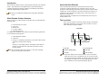
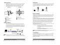
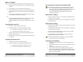
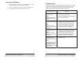
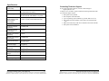
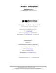
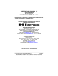
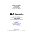
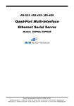
USB Extender
Model UEC100M/4
707 Dayton Road -- P.O. Box 1040 -- Ottawa, IL 61350 USA
Phone (815) 433-5100 -- General Fax (815) 433-5105
Phone (815) 433-5100 -- General Fax (815) 433-5105
Website: www.bb-elec.com
Sales e-mail: [email protected] -- Fax (815) 433-5109
Technical Support e-mail: [email protected] -- Fax (815) 433-5104
European Headquarters
B&B Electronics
Westlink Commercial Park -- Oranmore, Co. Galway, Ireland
Phone +353 91-792444 -- Fax +353 91-792445
Website: www.bb-europe.com
Sales e-mail: [email protected]
Technical Support e-mail: [email protected]
B&B Electronics Mfg. Co. Inc. -- June 2005
Manual Documentation Number: UEC100M/4-2305
B&B Electronics Mfg Co Inc – 707 Dayton Rd - PO Box 1040 - Ottawa IL 61350 - Ph 815-433-5100 - Fax 815-433-5104 – www.bb-elec.com
B&B Electronics – Westlink Commercial Park – Oranmore, Galway, Ireland – Ph +353 91-792444 – Fax +353 91-792445 – www.bb-europe.com
Thank you for purchasing the Ulinx Extender. Please
read this guide thoroughly before installation.
This document applies to Part Numbers: UEC100M/4, UEC100M/4-EU and
UEC100M/4-UK.
FCC Radio Frequency Interference Statement Warning
The Ulinx Extender has been tested and found compliant with the limits for a
Class A digital device, pursuant to Part 15 of the FCC Rules. These limits
are designed to provide reasonable protection against harmful interference
when installed and operated in a commercial environment. The Ulinx
Extender generates, uses, and can radiate radio frequency energy and, if
not installed and used in accordance with this user guide, may cause
harmful interference to radio communications. Operation of the Ulinx
Extender in a residential area is likely to cause harmful interference in which
case the user will be required to correct the interference at his own expense.
CE Statement
Conforms with European Standard EN 55022/A1 Class A, and EN 50082-1
(IEC 801-2, IEC 801-3, IEC 801-4)
IC Statement
This Class A digital apparatus complies with Canadian ICES-003.
Manual Documentation Number: UEC100M/4-2305
B&B Electronics Mfg Co Inc – 707 Dayton Rd - PO Box 1040 - Ottawa IL 61350 - Ph 815-433-5100 - Fax 815-433-5104 – www.bb-elec.com
B&B Electronics – Westlink Commercial Park – Oranmore, Galway, Ireland – Ph +353 91-792444 – Fax +353 91-792445 – www.bb-europe.com
Table of Contents
INTRODUCTION ........................................................................................... 1
ULINX EXTENDER PRODUCT CONTENTS ..................................................... 1
ABOUT THE ULINX EXTENDER .................................................................... 2
BEFORE YOU BEGIN .................................................................................... 5
INSTALLING THE LOCAL UNIT ..................................................................... 5
INSTALLING THE REMOTE UNIT .................................................................. 5
CONNECTING THE LOCAL UNIT TO THE REMOTE UNIT ............................... 6
CHECKING THE INSTALLATION .................................................................... 6
CONNECTING A USB DEVICE ...................................................................... 7
TROUBLESHOOTING .................................................................................... 8
SPECIFICATIONS ........................................................................................ 11
CONTACTING TECHNICAL SUPPORT .......................................................... 12
Manual Documentation Number: UEC100M/4-2305
i
B&B Electronics Mfg Co Inc – 707 Dayton Rd - PO Box 1040 - Ottawa IL 61350 - Ph 815-433-5100 - Fax 815-433-5104 – www.bb-elec.com
B&B Electronics – Westlink Commercial Park – Oranmore, Galway, Ireland – Ph +353 91-792444 – Fax +353 91-792445 – www.bb-europe.com
ii
Manual Documentation Number: UEC100M/4-2305
B&B Electronics Mfg Co Inc – 707 Dayton Rd - PO Box 1040 - Ottawa IL 61350 - Ph 815-433-5100 - Fax 815-433-5104 – www.bb-elec.com
B&B Electronics – Westlink Commercial Park – Oranmore, Galway, Ireland – Ph +353 91-792444 – Fax +353 91-792445 – www.bb-europe.com
Introduction
This manual is intended to assist IT professionals install the Ulinx Extender
model . The instructions in this guide assume a general knowledge of
computer installation procedures, familiarity with cabling requirements,
and some understanding of USB devices.
NOTE:
Notes give additional information that could make installation
easier.
Ulinx Extender Product Contents
When you open your Ulinx Extender for the first time you should find the
following items:
About the Ulinx Extender
The Ulinx Extender breaks the five-meter distance barrier for the
connection of USB peripheral devices and allows users to enjoy the
benefits of USB technology beyond the desktop. With the Ulinx Extender,
USB devices can be located up to 100 meters from the host computer. In
addition, the Ulinx Extender can supply power to remote low-power or
high-power USB devices.
The Ulinx Extender is composed of two individual units, the Local Unit
and the Remote Unit.
The Local Unit
The Local Unit connects to the host computer using a conventional
USB cable. Depending on your needs, it also connects to a power
outlet through an AC power adapter.
• Ulinx Extender User Guide
• Local Unit
• Remote Unit
• AC power adapter
• USB cable (2m long)
To complete the installation, you will also require the following items that
are not included with the product:
Front View
• USB compatible computer
• USB device
• Category 5 Unshielded Twisted Pair (UTP) cable with two RJ45
connectors (if using surface cabling),
OR,
Category 5 UTP cabling with two information outlets and two
Category 5 UTP patch cords with RJ45 connectors (if using
premise cabling)
NOTE:
2
1
2
4
1 Host LED
4 Link Port (RJ45)
2 Host Port (USB Type B)
5 Power LED
3 Link LED
6 Power connector
NOTE:
Manual Documentation Number: UEC100M/4-2305
5
6
The maximum length of the Category 5 UTP cable, including
patch cords, must not exceed 100m.
B&B Electronics Mfg Co Inc – 707 Dayton Rd - PO Box 1040 - Ottawa IL 61350 - Ph 815-433-5100 - Fax 815-433-5104 – www.bb-elec.com
B&B Electronics – Westlink Commercial Park – Oranmore, Galway, Ireland – Ph +353 91-792444 – Fax +353 91-792445 – www.bb-europe.com
3
1
The power adapter for the Ulinx Extender can be connected to
either the Local Unit or to the Remote Unit, as convenient. With
the Ulinx Extender UEC100M/4, the location of the power adapter
also depends on whether you are connecting high-power or lowpower USB devices. (See Power Handling on page 4).
Manual Documentation Number: UEC100M/4-2305
B&B Electronics Mfg Co Inc – 707 Dayton Rd - PO Box 1040 - Ottawa IL 61350 - Ph 815-433-5100 - Fax 815-433-5104 – www.bb-elec.com
B&B Electronics – Westlink Commercial Park – Oranmore, Galway, Ireland – Ph +353 91-792444 – Fax +353 91-792445 – www.bb-europe.com
USB Cables
The Remote Unit
The Remote Unit connects to the USB device using a conventional
USB cable. Depending on your needs, it also connects to a power
outlet through an AC power adapter. The Remote Unit of the
UEC100M/4 allows you to connect up to four USB devices.
Front View
USB cables have two distinct connectors. The Type A connector is used to
connect the cable from a USB device to the Type A port on a computer or
hub. The Type B connector is used to attach the USB cable to a USB
device.
Rear View
5
1
3
USB Type A
port
USB Type A
connector
USB Type B
port
USB Type B
connector
4
Power Handling
2
6
1 Link LED
5 Device LED(s)
2 Link Port (RJ45)
6 Device Port(s) (USB Type
A)
3 Power LED
4 Power connector
Network Cabling
The Local Unit and Remote Unit are interconnected by up to 100
meters of Category 5 Unshielded Twisted Pair (UTP) cabling. The
UTP cabling must have a straight-through conductor configuration,
with no crossovers, and must be terminated with 8-conductor RJ45
connectors at both ends.
Local
Unit
USB
Remote
Unit
Category 5 cable
cable
NOTE:
USB
cable(s)
computer
USB
device(s)
Devices with their own power source are usually considered to be
low-power devices from a USB perspective.
Compatibility
AC power adapter
NOTE: Category
5 UTP cabling is the standard data communications
cable installed in most commercial and some residential buildings.
Manual Documentation Number: UEC100M/4-2305
Some USB devices are powered directly from the USB and do not require
individual power supplies. These devices are called bus-powered devices.
The Ulinx Extender can provide power to these devices so they can be
operated remotely.
Bus-powered devices are further divided into low-power and high-power
categories. Low-power devices are allowed to draw up to 100 mA from the
USB. Typical examples include mice, joysticks, and keyboards without
hubs. High-power devices are allowed to draw up to 500 mA from the
USB. Typical examples include cameras and keyboards with hubs. To
determine if a device is high-power or low-power, consult the user
documentation for the device.
The Ulinx Extender UEC100M/4 can supply power to both low-power and
high-power devices when configured as follows:
• To operate up to four low-power devices, connect the
power adapter to the Local Unit or the Remote Unit, as
convenient.
• To operate up to four high-power devices, connect the
power adapter to the Remote Unit.
3
B&B Electronics Mfg Co Inc – 707 Dayton Rd - PO Box 1040 - Ottawa IL 61350 - Ph 815-433-5100 - Fax 815-433-5104 – www.bb-elec.com
B&B Electronics – Westlink Commercial Park – Oranmore, Galway, Ireland – Ph +353 91-792444 – Fax +353 91-792445 – www.bb-europe.com
The Ulinx Extender complies with USB 1.1 specifications governing the
design of full speed USB devices. However, B&B Electronics does not
guarantee that all full speed USB devices are compatible with the Ulinx
Extender UEC100M/4.
4
Manual Documentation Number: UEC100M/4-2305
B&B Electronics Mfg Co Inc – 707 Dayton Rd - PO Box 1040 - Ottawa IL 61350 - Ph 815-433-5100 - Fax 815-433-5104 – www.bb-elec.com
B&B Electronics – Westlink Commercial Park – Oranmore, Galway, Ireland – Ph +353 91-792444 – Fax +353 91-792445 – www.bb-europe.com
Before You Begin
Before you can install the Ulinx Extender, you need to prepare your site.
1. Determine where the host computer is to be located and set up the
computer.
2.
Determine where you want to locate the USB device(s).
3.
Decide whether the power adapter is to be connected to the Local
Unit or the Remote Unit (see the discussion of power handling on
page 4).
4.
If you are using surface cabling, ensure you have enough Category
5 UTP cabling to connect the two locations.
Connecting the Local Unit to the Remote Unit
NOTE: To
ensure proper operation, we recommend that only Category 5
or better, Unshielded Twisted Pair (UTP) cabling be used to
connect the Local Unit to the Remote Unit. The UTP cabling must
have a straight-through conductor configuration with no
crossovers, and must be terminated with 8-conductor RJ45
connectors at both ends.
With Surface Cabling
OR
1. Plug one end of the Category 5 UTP cabling (not included) into the
Link port on the Local Unit.
If you are using premise cabling, ensure Category 5 UTP cabling
is installed between the two locations, with Category 5
information outlets located near both the computer and the USB
device.
With Premise Cabling
Installing the Local Unit
1.
Place the Local Unit near the host computer.
2.
If the power adapter is to be located with the Local Unit:
a)
2. Plug the other end of the Category 5 UTP cabling into the Link port
on the Remote Unit.
1. Plug one end of a Category 5 patch cord (not included) into the Link
port on the Local Unit.
2. Plug the other end of the patch cord into the Category 5 information
outlet near the host computer.
Plug the power adapter into a suitable AC outlet.
3. Plug one end of the second Category 5 patch cord (not included)
into the Link port on the Remote Unit.
b) Connect the power adapter to the Local Unit.
3.
4.
Plug the Type B connector on the USB cable (included) into the
Host port on the Local Unit.
4. Plug the other end of the second patch cord into the Category 5
information outlet near the USB device.
Plug the Type A connector on the USB cable into the USB port on
the computer.
Installing the Remote Unit
1.
Place the Remote Unit near the USB device(s).
2.
If the power adapter is to be located with the Remote Unit:
a)
NOTE:
Checking the Installation
1.
2.
Plug the power adapter into a suitable AC outlet.
b) Connect the power adapter to the Remote Unit.
Manual Documentation Number: UEC100M/4-2305
The maximum length of the Category 5 UTP cable, including
patch cords, must not exceed 100 meters.
3.
4.
5
B&B Electronics Mfg Co Inc – 707 Dayton Rd - PO Box 1040 - Ottawa IL 61350 - Ph 815-433-5100 - Fax 815-433-5104 – www.bb-elec.com
B&B Electronics – Westlink Commercial Park – Oranmore, Galway, Ireland – Ph +353 91-792444 – Fax +353 91-792445 – www.bb-europe.com
6
Check that the Power LEDs on the Local Unit and Remote Unit
are both on.
Check that the Link LEDs on the Local Unit and Remote Unit are
both on.
Check that the Host LED on the Local Unit is on.
On the host PC, open the Device Manager applet. Expand the
entry for Universal Serial Bus controllers by clicking the + sign. If
the Ulinx Extender has been installed correctly you should find it
listed as a Generic USB Hub.
Manual Documentation Number: UEC100M/4-2305
B&B Electronics Mfg Co Inc – 707 Dayton Rd - PO Box 1040 - Ottawa IL 61350 - Ph 815-433-5100 - Fax 815-433-5104 – www.bb-elec.com
B&B Electronics – Westlink Commercial Park – Oranmore, Galway, Ireland – Ph +353 91-792444 – Fax +353 91-792445 – www.bb-europe.com
Connecting a USB Device
1.
Install any software required to operate the USB device(s). Refer
to the documentation for the device(s), as required.
2.
Connect the USB device to the Device port on the Remote Unit.
3.
Check that the Device LED on the Remote Unit is on.
Troubleshooting
The following table provides troubleshooting help. The topics are arranged
in the order in which they should be executed in most situations. If you are
unable to resolve the problem after following these instructions, please
contact technical support for further assistance (see page 12).
Symptoms/Cause
All LEDs on Local Unit and
Remote Unit are off.
Cause:
The Ulinx Extender is not
receiving power from the
adapter
Remedy
1. Ensure that the power adapter is connected to
the Local Unit or Remote Unit
2. Check that the adapter is connected to a live
source of electrical power
Power LED on one unit is
1. Ensure that a Category 5 UTP cable with
on, power LED on other unit
straight-through conductors is connected
is off.
between the Local Unit and Remote Unit.
Cause:
2. Connect a short Category 5 patch cord
There is no connection
between the Local Unit and Remote Unit.
between the Local Unit and
Recheck the operation of the system.
Remote Unit.
Link LEDs on Local Unit
and Remote Unit are off.
Cause:
There is no connection
between the Local Unit and
Remote Unit.
3. Ensure that a Category 5 UTP cable with
straight-through conductors is connected
between the Local Unit and Remote Unit.
USB Hub Power
Exceeded message is
displayed by the computer.
5. Move the power adapter from the Local Unit to
the Remote Unit.
4. Connect a short Category 5 patch cord
between the Local Unit and Remote Unit.
Recheck the operation of the system.
Cause:
The USB device connected
to the Remote Unit is a
high-power device and the
power adapter is connected
to the Local Unit
Manual Documentation Number: UEC100M/4-2305
7
B&B Electronics Mfg Co Inc – 707 Dayton Rd - PO Box 1040 - Ottawa IL 61350 - Ph 815-433-5100 - Fax 815-433-5104 – www.bb-elec.com
B&B Electronics – Westlink Commercial Park – Oranmore, Galway, Ireland – Ph +353 91-792444 – Fax +353 91-792445 – www.bb-europe.com
8
Manual Documentation Number: UEC100M/4-2305
B&B Electronics Mfg Co Inc – 707 Dayton Rd - PO Box 1040 - Ottawa IL 61350 - Ph 815-433-5100 - Fax 815-433-5104 – www.bb-elec.com
B&B Electronics – Westlink Commercial Park – Oranmore, Galway, Ireland – Ph +353 91-792444 – Fax +353 91-792445 – www.bb-europe.com
Symptoms/Cause
Remedy
Link LED on Local Unit is
on;
Host LED on Local Unit is
off.
1. Disconnect all USB devices from the Remote
Unit.
Cause:
3. Disconnect and then reconnect the power
adapter to the Ulinx Extender.
a) The computer is not
functioning.
4. Reconnect the Local Unit to the computer.
b) The Local Unit is not
connected to the
computer.
5. In the Universal Serial Bus controllers section
of Device Manager, check that the Ulinx
Extender is recognised as a “Generic USB
Hub”.
c) The computer does not
support USB hubs.
2. Disconnect the Local Unit from the computer.
6. If the Ulinx Extender is not recognised, contact
technical support for assistance.
d) The Ulinx Extender is
malfunctioning.
A device is connected to
Remote Unit and the
corresponding Device LED
is off
Cause:
a) The USB device is
malfunctioning.
b) The computer does not
recognise the USB
device.
c) The application software
for the device is not
operating.
d) The Ulinx Extender is
malfunctioning.
Symptoms/Cause
All LEDs on both the Local
Unit and Remote Unit are
on but the device does not
operate correctly
Cause:
a) The USB device is
malfunctioning.
b) The computer does not
recognise the USB
device.
c) The application software
for the device is not
operating.
d) The Ulinx Extender is
malfunctioning.
1. Disconnect the Ulinx Extender from the
computer.
2. Connect the USB device directly to the USB
port on the computer.
Remedy
1. Disconnect the Ulinx Extender from the
computer.
2. Connect the USB device directly to the USB
port on the computer.
3. If the device does not operate properly,
consult the user documentation for the device.
4. If the device operates properly when directly
connected to the computer, connect another
device (of a different type) to the Ulinx
Extender. Connect the Ulinx Extender to the
computer.
5. If the second device does not operate, the
Ulinx Extender may be malfunctioning.
Contact technical support for assistance.
6. If the second device does operate properly,
the first device may not be compatible with the
Ulinx Extender. Contact technical support for
assistance.
Manual Documentation Number: UEC100M/4-2305
9
B&B Electronics Mfg Co Inc – 707 Dayton Rd - PO Box 1040 - Ottawa IL 61350 - Ph 815-433-5100 - Fax 815-433-5104 – www.bb-elec.com
B&B Electronics – Westlink Commercial Park – Oranmore, Galway, Ireland – Ph +353 91-792444 – Fax +353 91-792445 – www.bb-europe.com
10
Manual Documentation Number: UEC100M/4-2305
B&B Electronics Mfg Co Inc – 707 Dayton Rd - PO Box 1040 - Ottawa IL 61350 - Ph 815-433-5100 - Fax 815-433-5104 – www.bb-elec.com
B&B Electronics – Westlink Commercial Park – Oranmore, Galway, Ireland – Ph +353 91-792444 – Fax +353 91-792445 – www.bb-europe.com
Specifications
Contacting Technical Support
Range (over Category
5 UTP cable)
100 meters (330 ft)
USB device support
Full speed devices (12 Mb/s)
Low speed devices (1.5 Mb/s)
USB hub support
Any single chain can include four USB hubs and
one Ulinx Extender UEC100M/4, in any order.
If you require technical assistance, send an e-mail message to:
[email protected]
To help us serve you better, please include the following information with
your technical support request:
•
•
•
•
Description of the problem
Host computer make and model
Type of operating system installed (e.g. Win98, Mac OS X, etc.)
Part number and serial number of the Local Unit and the Remote
Unit
• Make and model of any USB device attached to the Ulinx Extender
• Description of the installation
Power available to USB 4 x 100 mA (when powered at Local Unit)
4 x 500 mA (when powered at Remote Unit)
device at Remote Unit
(Ulinx Extender
UEC100M/4)
USB cable
2 meters (6.6 ft)
Local Unit connector
(upstream)
1 x USB Type B
Local Unit connector
(downstream)
1 x RJ45
Remote Unit connector
(upstream)
1 x RJ45
Remote Unit connector
(downstream)
4 x USB Type A
Local Unit dimensions
10.7 x 8.4 x 3.4 cm
4.3 x 3.4 x 1.4 in
Local Unit weight
0.3 kg (0.6 lb)
Remote Unit
dimensions
10.7 x 8.4 x 3.4 cm
4.3 x 3.4 x 1.4 in
Remote Unit weight
0.3 kg (0.6 lb)
Total system shipping
weight
1.1 kg (2.4 lb)
Temperature range
4°C to 40°C
Regulatory testing
FCC, CE Class A
Manual Documentation Number: UEC100M/4-2305
11
B&B Electronics Mfg Co Inc – 707 Dayton Rd - PO Box 1040 - Ottawa IL 61350 - Ph 815-433-5100 - Fax 815-433-5104 – www.bb-elec.com
B&B Electronics – Westlink Commercial Park – Oranmore, Galway, Ireland – Ph +353 91-792444 – Fax +353 91-792445 – www.bb-europe.com
12
Manual Documentation Number: UEC100M/4-2305
B&B Electronics Mfg Co Inc – 707 Dayton Rd - PO Box 1040 - Ottawa IL 61350 - Ph 815-433-5100 - Fax 815-433-5104 – www.bb-elec.com
B&B Electronics – Westlink Commercial Park – Oranmore, Galway, Ireland – Ph +353 91-792444 – Fax +353 91-792445 – www.bb-europe.com