1
Cisco MWR 1900 Mobile Wireless Edge
Router Software Configuration Guide
Corporate Headquarters
Cisco Systems, Inc.
170 West Tasman Drive
San Jose, CA 95134-1706
USA
http://www.cisco.com
Tel: 408 526-4000
800 553-NETS (6387)
Fax: 408 526-4100
Customer Order Number: DOC-7813983=
Text Part Number: 78-13983-04
THE SPECIFICATIONS AND INFORMATION REGARDING THE PRODUCTS IN THIS MANUAL ARE SUBJECT TO CHANGE WITHOUT NOTICE. ALL
STATEMENTS, INFORMATION, AND RECOMMENDATIONS IN THIS MANUAL ARE BELIEVED TO BE ACCURATE BUT ARE PRESENTED WITHOUT
WARRANTY OF ANY KIND, EXPRESS OR IMPLIED. USERS MUST TAKE FULL RESPONSIBILITY FOR THEIR APPLICATION OF ANY PRODUCTS.
THE SOFTWARE LICENSE AND LIMITED WARRANTY FOR THE ACCOMPANYING PRODUCT ARE SET FORTH IN THE INFORMATION PACKET THAT
SHIPPED WITH THE PRODUCT AND ARE INCORPORATED HEREIN BY THIS REFERENCE. IF YOU ARE UNABLE TO LOCATE THE SOFTWARE LICENSE
OR LIMITED WARRANTY, CONTACT YOUR CISCO REPRESENTATIVE FOR A COPY.
The following information is for FCC compliance of Class A devices: This equipment has been tested and found to comply with the limits for a Class A digital device, pursuant
to part 15 of the FCC rules. These limits are designed to provide reasonable protection against harmful interference when the equipment is operated in a commercial
environment. This equipment generates, uses, and can radiate radio-frequency energy and, if not installed and used in accordance with the instruction manual, may cause
harmful interference to radio communications. Operation of this equipment in a residential area is likely to cause harmful interference, in which case users will be required
to correct the interference at their own expense.
The following information is for FCC compliance of Class B devices: The equipment described in this manual generates and may radiate radio-frequency energy. If it is not
installed in accordance with Cisco’s installation instructions, it may cause interference with radio and television reception. This equipment has been tested and found to
comply with the limits for a Class B digital device in accordance with the specifications in part 15 of the FCC rules. These specifications are designed to provide reasonable
protection against such interference in a residential installation. However, there is no guarantee that interference will not occur in a particular installation.
Modifying the equipment without Cisco’s written authorization may result in the equipment no longer complying with FCC requirements for Class A or Class B digital
devices. In that event, your right to use the equipment may be limited by FCC regulations, and you may be required to correct any interference to radio or television
communications at your own expense.
You can determine whether your equipment is causing interference by turning it off. If the interference stops, it was probably caused by the Cisco equipment or one of its
peripheral devices. If the equipment causes interference to radio or television reception, try to correct the interference by using one or more of the following measures:
• Turn the television or radio antenna until the interference stops.
• Move the equipment to one side or the other of the television or radio.
• Move the equipment farther away from the television or radio.
• Plug the equipment into an outlet that is on a different circuit from the television or radio. (That is, make certain the equipment and the television or radio are on circuits
controlled by different circuit breakers or fuses.)
Modifications to this product not authorized by Cisco Systems, Inc. could void the FCC approval and negate your authority to operate the product.
The Cisco implementation of TCP header compression is an adaptation of a program developed by the University of California, Berkeley (UCB) as part of UCB’s public
domain version of the UNIX operating system. All rights reserved. Copyright © 1981, Regents of the University of California.
NOTWITHSTANDING ANY OTHER WARRANTY HEREIN, ALL DOCUMENT FILES AND SOFTWARE OF THESE SUPPLIERS ARE PROVIDED “AS IS” WITH
ALL FAULTS. CISCO AND THE ABOVE-NAMED SUPPLIERS DISCLAIM ALL WARRANTIES, EXPRESSED OR IMPLIED, INCLUDING, WITHOUT
LIMITATION, THOSE OF MERCHANTABILITY, FITNESS FOR A PARTICULAR PURPOSE AND NONINFRINGEMENT OR ARISING FROM A COURSE OF
DEALING, USAGE, OR TRADE PRACTICE.
IN NO EVENT SHALL CISCO OR ITS SUPPLIERS BE LIABLE FOR ANY INDIRECT, SPECIAL, CONSEQUENTIAL, OR INCIDENTAL DAMAGES, INCLUDING,
WITHOUT LIMITATION, LOST PROFITS OR LOSS OR DAMAGE TO DATA ARISING OUT OF THE USE OR INABILITY TO USE THIS MANUAL, EVEN IF CISCO
OR ITS SUPPLIERS HAVE BEEN ADVISED OF THE POSSIBILITY OF SUCH DAMAGES.
CCIP, the Cisco Arrow logo, the Cisco Powered Network mark, the Cisco Systems Verified logo, Cisco Unity, Follow Me Browsing, FormShare, Internet Quotient, iQ
Breakthrough, iQ Expertise, iQ FastTrack, the iQ Logo, iQ Net Readiness Scorecard, Networking Academy, ScriptShare, SMARTnet, TransPath, and Voice LAN are
trademarks of Cisco Systems, Inc.; Changing the Way We Work, Live, Play, and Learn, Discover All That’s Possible, The Fastest Way to Increase Your Internet Quotient,
and iQuick Study are service marks of Cisco Systems, Inc.; and Aironet, ASIST, BPX, Catalyst, CCDA, CCDP, CCIE, CCNA, CCNP, Cisco, the Cisco Certified Internetwork
Expert logo, Cisco IOS, the Cisco IOS logo, Cisco Press, Cisco Systems, Cisco Systems Capital, the Cisco Systems logo, Empowering the Internet Generation,
Enterprise/Solver, EtherChannel, EtherSwitch, Fast Step, GigaStack, IOS, IP/TV, LightStream, MGX, MICA, the Networkers logo, Network Registrar, Packet, PIX,
Post-Routing, Pre-Routing, RateMUX, Registrar, SlideCast, StrataView Plus, Stratm, SwitchProbe, TeleRouter, and VCO are registered trademarks of Cisco Systems, Inc.
and/or its affiliates in the U.S. and certain other countries.
All other trademarks mentioned in this document or Web site are the property of their respective owners. The use of the word partner does not imply a partnership relationship
between Cisco and any other company. (0206R)
Cisco MWR 1900 Mobile Wireless Edge Router Software Configuration Guide
Copyright © 2002 Cisco Systems, Inc.
All rights reserved.
C O N T E N T S
About This Guide
Objectives
Audience
vii
vii
vii
Organization
vii
Document Conventions
viii
Additional Information
ix
Related Documentation
ix
Obtaining Documentation
World Wide Web
ix
ix
Documentation CD-ROM
x
Ordering Documentation
x
Documentation Feedback
x
Obtaining Technical Assistance
Cisco.com
x
xi
Technical Assistance Center
CHAPTER
1
Overview of the MWR 1900
Benefits
xi
1-1
1-1
Software Features
1-2
Cisco IOS Software
1-2
Network Processor Software
1-2
PPP Multiplexing/Demultiplexing
RTP/UDP Header Compression
Redundancy Support
MIB Support
2
1-5
First-Time Configuration
Before You Begin
1-3
1-4
Limitations and Restrictions
CHAPTER
1-3
1-6
2-1
2-1
Understanding Boot Images
2-1
Understanding Interface Numbering
Before Starting Your Router
2-1
2-3
Cisco MWR 1900 Mobile Wireless Edge Router Software Configuration Guide
78-13983-04
iii
Contents
Using the Setup Command Facility
Configuring Global Parameters
Completing the Configuration
Where to Go Next
CHAPTER
3
2-3
2-5
2-6
Cisco IOS Software Basics
Getting Help
2-3
3-1
3-1
Understanding Command Modes
3-2
Undoing a Command or Feature
3-3
Saving Configuration Changes
Where to Go Next
CHAPTER
4
3-3
3-3
Configuring with the Command-Line Interface
Before You Begin
4-1
4-2
Verifying the Version of Cisco IOS Software
Configuring the Host Name and Password
Configuring Loopback Interfaces
4-2
4-2
4-3
Configuring Fast Ethernet Interfaces
4-4
Configuring the FE Interface IP Address
Setting the Speed and Duplex Mode
4-4
4-4
Configuring Routing Protocol Attributes
Configuring PIM
4-5
Configuring HSRP Support
Enabling the FE Interface
4-6
4-7
Configuring Multilink Interfaces
Configuring Multilink PPP
4-7
4-8
Configuring IP Address Assignment
Configuring PPP Multiplexing
4-8
4-9
Configuring RTP/UDP Compression
4-9
Configuring Routing Protocol Attributes
Configuring PIM
4-5
4-10
4-10
Configuring T1 and E1 Interfaces
4-11
Configuring T1 Interfaces
4-11
Configuring E1 Interfaces
4-12
Cisco MWR 1900 Mobile Wireless Edge Router Software Configuration Guide
iv
78-13983-04
Contents
Configuring QoS Attributes
4-13
Creating a Class Map
4-14
Creating a Policy Map
4-14
Assigning a QoS Boilerplate to an Interface
Configuring Redundancy
4-16
4-16
Redundant MWR 1900s
4-16
Stand-Alone MWR 1900
4-17
Saving Configuration Changes
Verifying the Configuration
4-18
4-18
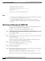
Monitoring and Managing the MWR 1900
4-22
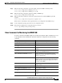
Show Commands for Monitoring the MWR 1900
CHAPTER
5
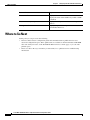
Where to Go Next
4-24
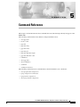
Command Reference
5-1
clear ip rtp header-compression
clear ppp mux
ip rtp header-compression
mode y-cable
5-4
5-5
5-7
5-8
ppp mux delay
5-9
ppp mux frame
5-10
ppp mux pid
5-11
ppp mux subframe length
ppp mux subframe count
redundancy
5-12
5-13
5-14
show ip rtp header-compression
show ppp mux
5-15
5-17
show redundancy
standalone
5-2
5-3
ip rtp compression-connections
ppp mux
4-23
5-19
5-21
standby use-interface
5-22
INDEX
Cisco MWR 1900 Mobile Wireless Edge Router Software Configuration Guide
78-13983-04
v
Contents
Cisco MWR 1900 Mobile Wireless Edge Router Software Configuration Guide
vi
78-13983-04
About This Guide
This preface discusses the objectives, audience, organization, and conventions of this software
configuration guide, and where to get the latest version of this guide.
Objectives
This guide explains how to configure features that enable the MWR 1900 to be used in an IP-RAN
solution.
Audience
This publication is designed for the person who will be responsible for configuring the router. This guide
is intended for the following audiences:
•
Customers with technical networking background and experience
•
System administrators who are familiar with the fundamentals of router-based internetworking, but
who might not be familiar with Cisco IOS software
•
System administrators who are responsible for installing and configuring internetworking
equipment, and who are familiar with Cisco IOS software
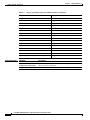
Organization
The major sections of this software configuration guide include:
Chapter
Title
Description
Chapter 1 Overview of the MWR 1900
Describes the purpose of the MWR 1900 and its unique
software features.
Chapter 2 First-Time Configuration
Discusses using the setup command facility to configure
basic attributes of your router.
Chapter 3 Cisco IOS Software Basics
Describes what you need to know about the Cisco IOS
software.
Cisco MWR 1900 Mobile Wireless Edge Router Software Configuration Guide
78-13983-04
vii
About This Guide
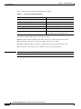
Document Conventions
Chapter
Title
Description
Chapter 4 Configuring with the
Command-Line Interface
Describes how to use the Cisco IOS software
command-line interface (CLI) to configure basic router
functionality.
Chapter 5 Command Reference
Provides information about new and changed commands.
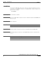
Document Conventions
This publication uses the following conventions to convey instructions and information.
Note
Convention
Description
boldface font
Commands and keywords.
italic font
Variables for which you supply values.
[
Keywords or arguments that appear within square brackets are optional.
]
{x | y | z}
A choice of required keywords appears in braces separated by vertical bars.
You must select one.
screen font
Examples of information displayed on the screen.
boldface screen
font
Examples of information you must enter.
<
>
Nonprinting characters, for example passwords, appear in angle brackets in
contexts where italic font is not available.
[
]
Default responses to system prompts appear in square brackets.
Means reader take note. Notes contain helpful suggestions or references to additional
information and material.
Timesaver
This symbol means the described action saves time. You can save time by performing the
action described in the paragraph.
Caution
This symbol means reader be careful. In this situation, you might do something that could
result in equipment damage or loss of data.
Tips
This symbol means the following information will help you solve a problem. The tips
information might not be troubleshooting or even an action, but could be useful
information, similar to a Timesaver.
Cisco MWR 1900 Mobile Wireless Edge Router Software Configuration Guide
viii
78-13983-04
About This Guide
Additional Information
Additional Information
This configuration guide does not contain the following:
•
Network design guide
•
Application case studies
•
Troubleshooting guide
•
A comprehensive reference to access services
For additional information about any of these topics, refer to the following resources:
•
Documentation CD-ROM
•
Cisco Connection Online (CCO)
•
Customer Service
•
Technical Assistance Center (TAC)
•
European TAC
Related Documentation
The following is a list of related Cisco MWR 1900 Mobile Wireless Edge Router publications.
•
Release Notes for the Cisco MWR 1900 Mobile Wireless Edge Router for Cisco IOS Release
12.2 MC
•
Cisco MWR 1900 Hardware Installation Guide
•
MWR 1900 Mobile Wireless Edge Router Rack Mounting Instructions
•
Regulatory Compliance and Safety Information for the Cisco MWR 1900 Mobile Wireless Edge
Router
Obtaining Documentation
The following sections provide sources for obtaining documentation from Cisco Systems.
World Wide Web
You can access the most current Cisco documentation on the World Wide Web at the following sites:
•
http://www.cisco.com
•
http://www-china.cisco.com
•
http://www-europe.cisco.com
Cisco MWR 1900 Mobile Wireless Edge Router Software Configuration Guide
78-13983-04
ix
About This Guide
Obtaining Technical Assistance
Documentation CD-ROM
Cisco documentation and additional literature are available in a CD-ROM package, which ships
with your product. The Documentation CD-ROM is updated monthly and may be more current than
printed documentation. The CD-ROM package is available as a single unit or as an annual subscription.
Ordering Documentation
Cisco documentation is available in the following ways:
•
Registered Cisco Direct Customers can order Cisco Product documentation from the Networking
Products MarketPlace:
http://www.cisco.com/cgi-bin/order/order_root.pl
•
Registered Cisco.com users can order the Documentation CD-ROM through the online Subscription
Store:
http://www.cisco.com/go/subscription
•
Nonregistered Cisco.com users can order documentation through a local account representative by
calling Cisco corporate headquarters (California, USA) at 408 526-7208 or, in North America, by
calling 800 553-NETS(6387).
Documentation Feedback
If you are reading Cisco product documentation on the World Wide Web, you can submit technical
comments electronically. Click Feedback in the toolbar and select Documentation. After you complete
the form, click Submit to send it to Cisco.
You can e-mail your comments to [email protected].
To submit your comments by mail, for your convenience many documents contain a response card
behind the front cover. Otherwise, you can mail your comments to the following address:
Cisco Systems, Inc.
Document Resource Connection
170 West Tasman Drive
San Jose, CA 95134-9883
We appreciate your comments.
Obtaining Technical Assistance
Cisco provides Cisco.com as a starting point for all technical assistance. Customers and partners can
obtain documentation, troubleshooting tips, and sample configurations from online tools. For Cisco.com
registered users, additional troubleshooting tools are available from the TAC website.
Cisco MWR 1900 Mobile Wireless Edge Router Software Configuration Guide
x
78-13983-04
About This Guide
Obtaining Technical Assistance
Cisco.com
Cisco.com is the foundation of a suite of interactive, networked services that provides immediate, open
access to Cisco information and resources at anytime, from anywhere in the world. This highly
integrated Internet application is a powerful, easy-to-use tool for doing business with Cisco.
Cisco.com provides a broad range of features and services to help customers and partners streamline
business processes and improve productivity. Through Cisco.com, you can find information about Cisco
and our networking solutions, services, and programs. In addition, you can resolve technical issues with
online technical support, download and test software packages, and order Cisco learning materials and
merchandise. Valuable online skill assessment, training, and certification programs are also available.
Customers and partners can self-register on Cisco.com to obtain additional personalized information and
services. Registered users can order products, check on the status of an order, access technical support,
and view benefits specific to their relationships with Cisco.
To access Cisco.com, go to the following website:
http://www.cisco.com
Technical Assistance Center
The Cisco TAC website is available to all customers who need technical assistance with a Cisco product
or technology that is under warranty or covered by a maintenance contract.
Contacting TAC by Using the Cisco TAC Website
If you have a priority level 3 (P3) or priority level 4 (P4) problem, contact TAC by going to the TAC
website:
http://www.cisco.com/tac
P3 and P4 level problems are defined as follows:
•
P3—Your network performance is degraded. Network functionality is noticeably impaired, but most
business operations continue.
•
P4—You need information or assistance on Cisco product capabilities, product installation, or basic
product configuration.
In each of the above cases, use the Cisco TAC website to quickly find answers to your questions.
To register for Cisco.com, go to the following website:
http://www.cisco.com/register/
If you cannot resolve your technical issue by using the TAC online resources, Cisco.com registered users
can open a case online by using the TAC Case Open tool at the following website:
http://www.cisco.com/tac/caseopen
Cisco MWR 1900 Mobile Wireless Edge Router Software Configuration Guide
78-13983-04
xi
About This Guide
Obtaining Technical Assistance
Contacting TAC by Telephone
If you have a priority level 1(P1) or priority level 2 (P2) problem, contact TAC by telephone and
immediately open a case. To obtain a directory of toll-free numbers for your country, go to the following
website:
http://www.cisco.com/warp/public/687/Directory/DirTAC.shtml
P1 and P2 level problems are defined as follows:
•
P1—Your production network is down, causing a critical impact to business operations if service is
not restored quickly. No workaround is available.
•
P2—Your production network is severely degraded, affecting significant aspects of your business
operations. No workaround is available.
Cisco MWR 1900 Mobile Wireless Edge Router Software Configuration Guide
xii
78-13983-04
1
C H A P T E R
Overview of the MWR 1900
The MWR 1900 Mobile Wireless Edge Router is a networking platform optimized for use in mobile
wireless networks. It extends IP connectivity to the cell site and Base Transceiver Station (BTS), and
through a Fast Ethernet interface to the BTS, provides bandwidth-efficient IP transport of voice and data
bearer traffic, as well as maintenance, control, and signalling traffic, over the leased line backhaul
network between the BTS and leased line termination and aggregation node via compression
(cRTP/cUDP) and packet multiplexing (PPPmux and MLPPP). It supports a limited set of interfaces and
protocols, but offers high performance at a low cost while meeting the critical requirements for
deployment in cell sites, including small size, extended operating temperature range, high availability,
and DC input power flexibility.
Benefits
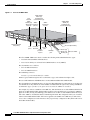
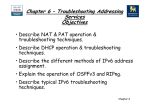
The MWR 1900 router is designed to be used at a cell site as part of an IP-RAN solution. Figure 1-1
shows the placement of and connections for the MWR 1900 for this application.
Figure 1-1
MWR 1900 in an IP-RAN Solution
Active
100BaseT
T1/E1 backhaul link to
IP RAN aggregation node
Standby
MWR 1900 IP BTS router pair
65827
pBTS
In the IP-RAN solution, the BTS site consists of a pair of MWR 1900 routers. The pair of MWR 1900s
provides for an active and standby router for redundancy. A failure of the active MWR 1900 causes the
standby router to take over as the active router for the BTS site.
Each pair of MWR 1900 routers at the BTS site is identical in hardware configuration. They connect to
each other through the BTS via the Fast Ethernet interfaces. The individual backhaul links to an MWR
1900 router are cabled from a single T1/E1 termination block in the BTS, connecting to both the active
and standby routers utilizing a “Y” cable. The redundancy design to control the active/standby
Cisco MWR 1900 Mobile Wireless Edge Router Software Configuration Guide
78-13983-04
1-1
Chapter 1
Overview of the MWR 1900
Software Features
transitions of the router pair leverages HSRP to control the relays on the VWIC-2MFT-T1-DIR (or
VWIC-2MFT-E1-DIR) in each router to ensure that the relays on the active router are closed and the
relays on the standby router are open to avoid double termination of the T1 (or E1).
Software Features
The software running on the MWR 1900 platform consists of two components: Cisco IOS software
running on the MIPs-based route processor portion of the MWR 1900 hardware, and microcode running
on the Cisco network processor, also known as “Parallel eXpress Forwarding (PXF).” Because the
MWR 1900 is designed specifically for deployment in an IP-RAN at the BTS, it is customized for
performance, high availability, quality of service, and link efficiency.
Cisco IOS Software
Cisco IOS software functions added to the MWR 1900 router for the IP-RAN application include:
•
Redundancy logic—For monitoring Hot Standby Routing Protocol (HSRP) information to
determine the active and standby router and control T1 termination.
•
Failover logic—To force a switchover for hardware failures or an over-temperature condition.
•
Relay control—To open and close the T1/E1 interfaces on the active and standby routers.
•
Diagnostic functions—To monitor the “health” of the standby MWR 1900 router.
Standard Cisco IOS software features supported in the MWR 1900 for the IP-RAN application include:
•
IP Fragmentation
•
IP Multicast
•
IGMP
•
MLP, PPP Control Path (IPCP, NCP, LCP, CLNS)
•
HSRP
•
OSPF
•
DHCP
•
CDP
•
NTP
•
SNMP
Network Processor Software
To achieve the required efficiency, the MWR 1900 router has microcode running on the network
processor to offload the fast-path processing of packets. This allows the MWR 1900 router to support
the traffic of up to 4 T1s or E1s (up to 60,000 packets per second) at a targeted 80% processor utilization
while performing UDP/RTP header compression/decompression (cUDP/cRTP) and PPPmux.
Cisco MWR 1900 Mobile Wireless Edge Router Software Configuration Guide
1-2
78-13983-04
Chapter 1
Overview of the MWR 1900
Software Features
The following features are supported in the network processor:
•
MAC Classify
•
ICMP
•
FIB (CEF)
•
Load-balancing
•
MAC Rewrite
•
QoS Matching, including IP Access Lists (Input/Output Security ACLs are not supported), QoS
Group, IP Precedence, IP DSCP, and Input Interface
•
QoS Actions, including Set IP Precedence, Set IP DSCP, Set QoS Group, Traffic Shaping, Class
Based WFQ (CB-WFQ), and Low Latency Queuing (LLQ)
•
Maintenance of statistics, such as Forwarding, Drop, and Interface
•
IPv4
•
MLPPP
•
MLP, PPP Data Path (MLP LFI is not supported)
•
PPPmux
•
cRTP/cUDP
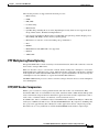
PPP Multiplexing/Demultiplexing
Encapsulated PPP frames contain several bytes of header information, which adds overhead to a network
that is used to transport PPP frames.
RFC 3153 describes a way to overcome this overhead. On the sending end, a multiplexor concatenates
multiple PPP frames (subframes) into a single, multiplexed frame (superframe). One header is included
in the superframe and the individual PPP subframes are separated by delimiters. On the receiving end,
a demultiplexor uses the delimiters to separate the individual PPP subframes.
The MWR 1900 network processor software conforms to this specification and acts as both a multiplexor
and a demultiplexor.
RTP/UDP Header Compression
RTP is a protocol used for carrying packetized audio and video traffic over an IP network. RTP,
described in RFC 1889, is not intended for data traffic, which uses TCP or UDP. Instead, RTP provides
end-to-end network transport functions intended for applications with real-time requirements (such as
audio, video, or simulation data) over multicast or unicast network services.
In an RTP frame, there is a minimum 12 bytes of the RTP header, combined with 20 bytes of IP header,
and 8 bytes of UDP header. This creates a 40-byte IP/UDP/RTP header. By comparison, the RTP packet
has a payload of approximately 20 to 160 bytes for audio applications that use compressed payloads.
Given this ratio, it is very inefficient to transmit the IP/UDP/RTP header without compressing it.
Cisco MWR 1900 Mobile Wireless Edge Router Software Configuration Guide
78-13983-04
1-3
Chapter 1
Overview of the MWR 1900
Software Features
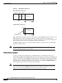
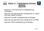
Figure 1-2
RTP Header Compression
Before RTP header compression:
20 bytes
IP
8 bytes 12 bytes
UDP
RTP
Header
Payload
20 to 160 bytes
After RTP header compression:
2 to 4 bytes
IP/UDP/RTP header
20 to 160 bytes
12076
Payload
RFCs 2508 and 2509 describe a method for compressing not only the RTP header, but also the associated
UDP and IP headers. Using this method, the 40 bytes of header information is compressed into
approximately 2 to 4 bytes, as shown in Figure 1-2. Because the frames are compressed on a link-by-link
basis, the delay and loss rate are lower, resulting in improved performance.
The MWR 1900 network processor offloads both the compression and decompression of RTP frames
from the Cisco IOS software.
Note
The MWR 1900 router can be configured to perform only IP/UDP compression, in which case the
header is reduced from 28 bytes to 2 to 4 bytes.
Redundancy Support
To ensure availability, the backhaul links to an MWR 1900 router are redundantly cabled to the
VWIC-2MFT-T1-DIR/ VWIC-2MFT-E1-DIR cards. This card, designed specifically for the MWR 1900
router, is a modified 2-port T1/E1 Multiflex VWIC with Drop and Insert.The modifications include the
addition of relays to activate the T1/E1 ports. The relays allow “Y” cabling for router redundancy where
the T1/E1 link is not redundant and default to open. The relays are controlled by HSRP/redundancy
protocol between the two routers connected to the same T1/E1.
Note
If you choose to use the MWR 1900 router in a non-redundant configuration, you must close the
relays on the card using the standalone subcommand. Also, redundancy parameters are processed
when the router is booted up. These parameters cannot be changed “on the fly.”
Cisco MWR 1900 Mobile Wireless Edge Router Software Configuration Guide
1-4
78-13983-04
Chapter 1
Overview of the MWR 1900
Software Features
HSRP
Cisco’s Hot Standby Router Protocol (HSRP) is used to control which router is active and which is
standby. HSRP uses a priority scheme to determine which HSRP-configured router is to be the default
active router. Priority is determined first by the configured priority value, and then by the IP address. In
each case a higher value is of greater priority.
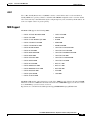
MIB Support
The MWR 1900 supports the following MIBs:
•
CISCO-ACCESS-ENVMON-MIB
•
CISCO-TCP-MIB
•
CISCO-CDP-MIB
•
ENTITY-MIB
•
CISCO-CLASS-BASED-QOS-MIB
•
IF-MIB
•
CISCO-CONFIG-COPY-MIB
•
IGMP-MIB
•
CISCO-CONFIG-MAN-MIB
•
IPMROUTE-MIB
•
CISCO-ENVMON-MIB
•
OLD-CISCO-CHASSIS-MIB
•
CISCO-FLASH-MIB
•
OLD-CISCO-FLASH-MIB
•
CISCO-HSRP-EXT-MIB
•
OLD-CISCO-INTERFACES-MIB
•
CISCO-HSRP-MIB
•
OLD-CISCO-IP-MIB
•
CISCO-ICSUDSU-MIB
•
OLD-CISCO-SYSTEM-MIB
•
CISCO-IMAGE-MIB
•
OLD-CISCO-TS-MIB
•
CISCO-IP-STAT-MIB
•
RFC1213-MIB
•
CISCO-IPMROUTE-MIB
•
RFC1253-MIB
•
CISCO-MEMORY-POOL-MIB
•
RFC1406-MIB
•
CISCO-PROCESS-MIB
•
TCP-MIB
•
CISCO-QUEUE-MIB
•
UDP-MIB
•
CISCO-SYSLOG-MIB
The MWR 1900 uses the same software base as the Cisco 10000. As such, it shares the same QoS MIB
limitations of the Cisco 10000. For information about the Cisco10000 MIB support, see the Cisco 10000
Series ESR MIB Specifications Guide on CCO at
http://www.cisco.com/univercd/cc/td/doc/product/aggr/10000/10kmibs/specgdll/index.htm.
Cisco MWR 1900 Mobile Wireless Edge Router Software Configuration Guide
78-13983-04
1-5
Chapter 1
Overview of the MWR 1900
Limitations and Restrictions
Limitations and Restrictions
The MWR 1900 requires a special release of Cisco IOS software. Not all Cisco IOS software features
can be used with this router as the core routing is handled by the network processor. A list of supported
features is included in the “Software Features” section on page 1-2. The following features are not
supported on the MWR 1900:
•
Security Access Control Lists
•
MPLS
•
802.1Q VLANs
•
Frame Relay (FR)
•
MLP LFI
•
ATM
•
Use of additional WICs (The only supported WIC is the VWIC-2MFT-T1DIR/
VWIC-2MFT-E1DIR.)
Cisco MWR 1900 Mobile Wireless Edge Router Software Configuration Guide
1-6
78-13983-04
C H A P T E R
2
First-Time Configuration
This chapter describes how to use the setup command facility to configure your router. The setup
command facility prompts you to enter information needed to start a router functioning quickly. The
facility steps you through a basic configuration, including local-area network (LAN) and wide-area
network (WAN) interfaces. The following sections are included:
•
Before You Begin, page 2-1
•
Using the Setup Command Facility, page 2-3
•
Configuring Global Parameters, page 2-3
•
Completing the Configuration, page 2-5
•
Where to Go Next, page 2-6
If you prefer to configure the router manually or you wish to configure a module or interface that is not
included in the setup command facility, proceed to “Chapter 3, “Cisco IOS Software Basics” to
familiarize yourself with the command-line interface (CLI) and then proceed to “Chapter 4,
“Configuring with the Command-Line Interface” for step-by-step instructions.
Before You Begin
This section contains information with which you should be familiar before you begin to configure your
router for the first time, including understanding boot images, understanding interface numbering, and
knowing what you should do before starting your router.
Understanding Boot Images
The first file on the compact flash device in slot0: must be the Cisco IOS software image that you want
to use. If it is not, the MWR 1900 will not be able to boot.
If you need to upgrade or replace the compact flash, be sure to follow the procedures in the Cisco MWR
1900 Mobile Wireless Router Hardware Installation Guide.
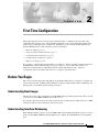
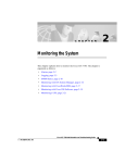
Understanding Interface Numbering
Each individual interface (port) on a Cisco MWR 1900 router is identified by number. Figure 2-1 shows
the front of the MWR 1900 with the Fast Ethernet ports and the Voice/WAN Interface Card (VWIC)
ports.
Cisco MWR 1900 Mobile Wireless Edge Router Software Configuration Guide
78-13983-04
2-1
Chapter 2
First-Time Configuration
Before You Begin
Figure 2-1
Front of the MWR 1900
VWIC LEDs:
Alarm (A)
Loopback (A)
Carrier detect (G)
Fast
ethernet
LEDs:
Activity (G) VWIC
Speed (G) position 2
(future)
Link (G)
SEE MAN
UAL BEFO
RE INST
ALLATION
VWIC LEDs:
Alarm (A)
Loopback (A)
Carrier detect (G)
VWIC
position 0
2 ports
DSU
56K
SEE MAN
UAL BEFO
RE INST
ALLATION
2 FE
ports
Compact
flash slot
E
AUXILIA
RY
Air vent (both sides)
Console
port
VWIC
position 1
2 ports
Auxiliary
port
Power (G)
Status (G)
Activity (G)
Chassis LEDs
65783
CONSOL
Network module
slot (future)
The Cisco MWR 1900 router chassis contains the following LAN and WAN interface types:
•
Two built-in Fast Ethernet LAN interfaces
•
Two slots in which you can install Voice/WAN interface cards (VWICs)
The slot numbers are as follows:
•
0 for all built-in interfaces
•
0 for all VWIC interfaces
The numbering format is:
Interface type Slot number/Interface number
Interface (port) numbers begin at 0 for each interface type, and continue from right to left.
The two built-in Ethernet 10/100 interfaces are Fast Ethernet 0/0 and Fast Ethernet 0/1.
The slot number for all VWIC interfaces is always 0. (The W0 and W1 slot designations are for physical
slot identification only.) Interfaces in the VWICs are numbered from right to left, starting with 0/0 for
each interface type, regardless of the physical slot in which the VWICs are installed.
For example, if you have a VWIC in each VWIC slot, then the interfaces are Serial 0/0 and Serial 0/1 in
physical slot W0 and Serial 0/2 and Serial 0/3 in physical slot W1. However, if you install a VWIC in
physical slot W1 (leaving slot W0 empty), the interfaces in slot W1 are Serial 0/0 and Serial 0/1. If you
then add a VWIC to slot W0, the interface numbering will shift. The configuration that you created for
interfaces Serial 0/0 and Serial 0/1 will now be applied to the VWIC in slot W0 and you will need to
create a new configuration for the interfaces that you previously configured on W1 (which will now be
Serial 0/2 and Serial 0/3).
Cisco MWR 1900 Mobile Wireless Edge Router Software Configuration Guide
2-2
78-13983-04
Chapter 2
First-Time Configuration
Using the Setup Command Facility
Before Starting Your Router
Before you power ON your router and begin to use the setup command facility, make sure you follow
these steps:
Step 1
Set up the hardware and connect the console and network cables as described in the Cisco MWR 1900
Router Hardware Installation Guide.
Step 2
Configure your PC terminal emulation program for 9600 baud, 8 data bits, no parity, and 1 stop bit.
Using the Setup Command Facility
The setup command facility displays from your PC terminal emulation program window.
To create a basic configuration for your router, do the following:
Note
•
Complete the steps in the “Configuring Global Parameters” section on page 2-3.
•
Complete the steps in the “Completing the Configuration” section on page 2-5.
If you make a mistake while using the setup command facility, you can exit and run the facility again.
Press Ctrl-c, and type setup at the enable mode prompt (1900#).
Configuring Global Parameters
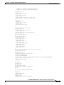
Step 1
Power ON the router, see the Cisco MWR 1900 Router Hardware Installation Guide.
Messages will begin to appear in your terminal emulation program window.
Caution
Do not press any keys on the keyboard until the messages stop. Any keys pressed during this time
are interpreted as the first command typed when the messages stop, which might cause the router to
power off and start over. It takes a few minutes for the messages to stop.
rommon 1 >b slot0:mwr1900-i-mz.12042001
program load complete, entry point:0x80008000, size:0x658258
Self decompressing the image :
############################################################################
############################################################################
############################################################################
############################################################################
############################################################################
############################################################################
############################################################################
####################### [OK]
Restricted Rights Legend
Use, duplication, or disclosure by the Government is
subject to restrictions as set forth in subparagraph
(c) of the Commercial Computer Software - Restricted
Cisco MWR 1900 Mobile Wireless Edge Router Software Configuration Guide
78-13983-04
2-3
Chapter 2
First-Time Configuration
Configuring Global Parameters
Rights clause at FAR sec. 52.227-19 and subparagraph
(c) (1) (ii) of the Rights in Technical Data and Computer
Software clause at DFARS sec. 252.227-7013.
cisco Systems, Inc.
170 West Tasman Drive
San Jose, California 95134-1706
Cisco Internetwork Operating System Software
IOS (tm) 10000 Software (MWR1900-I-M), Version 12.2(xy), EARLY DEPLOYMENT RELEASE SOFTWARE
Copyright (c) 1986-2001 by cisco Systems, Inc.
Compiled Tue 04-Dec-01 23:20 by jsmith
Image text-base:0x600089C0, data-base:0x60B42000
cisco mwr1900 (R7000) processor (revision 0.5) with 98304K/32768K bytes of
memory.
Processor board ID 12345678901
R7000 CPU at 240Mhz, Implementation 39, Rev 3.3, 256KB L2 Cache
Bridging software.
X.25 software, Version 3.0.0.
Primary Rate ISDN software, Version 1.1.
Toaster processor tmc has been reset.
2 FastEthernet/IEEE 802.3 interface(s)
2 Channelized T1/PRI port(s)
DRAM configuration is 64 bits wide with parity disabled.
55K bytes of non-volatile configuration memory.
39168K bytes of ATA Slot0 CompactFlash (Read/Write)
--- System Configuration Dialog --At any point you may enter a question mark '?' for help.
Use ctrl-c to abort configuration dialog at any prompt.
Default settings are in square brackets '[]'.
Step 2
When the following message appears, enter yes to begin the initial configuration dialog:
Basic management setup configures only enough connectivity
for management of the system, extended setup will ask you
to configure each interface on the system
Would you like to enter basic management setup? [yes/no]:y
Configuring global parameters:
Step 3
Enter a host name for the router (this example uses 1900-1):
Configuring global parameters:
Enter host name [Router]: 1900-1
Step 4
Enter an enable secret password. This password is encrypted (more secure) and cannot be seen when
viewing the configuration:
The enable secret is a password used to protect access to
privileged EXEC and configuration modes. This password, after
entered, becomes encrypted in the configuration.
Enter enable secret: xxxx
Step 5
Enter an enable password that is different from the enable secret password. This password is not
encrypted (less secure) and can be seen when viewing the configuration:
The enable password is used when you do not specify an
enable secret password, with some older software versions, and
some boot images.
Enter enable password: guessme
Cisco MWR 1900 Mobile Wireless Edge Router Software Configuration Guide
2-4
78-13983-04
Chapter 2
First-Time Configuration
Completing the Configuration
Step 6
Enter the virtual terminal password, which prevents unauthenticated access to the router through ports
other than the console port:
The virtual terminal password is used to protect
access to the router over a network interface.
Enter virtual terminal password: guessagain
Step 7
Respond to the following prompts as appropriate for your network:
Configure SNMP Network Management? [yes]:
Community string [public]:
Step 8
The summary of interfaces is displayed.
Current interface summary
Controller
T1 0/0
T1 0/1
T1 0/2
T1 0/3
Timeslots
24
24
24
24
Interface
FastEthernet0/0
FastEthernet0/1
Serial0/0:0
Serial0/1:0
Step 9
D-Channel
23
23
23
23
Configurable modes
pri/channelized
pri/channelized
pri/channelized
pri/channelized
IP-Address
172.18.46.74
150.0.1.0
unassigned
unassigned
OK?
YES
YES
YES
YES
Method
NVRAM
NVRAM
NVRAM
NVRAM
Status
Administratively
Administratively
Administratively
Administratively
Status
up
up
up
up
up
up
up
up
Protocol
up
up
up
up
Specify the interface to be used to connect to the network management system.
Enter interface name used to connect to the
management network from the above interface summary:FastEthernet0/0
Step 10
You are then prompted to configure the specified interface.
Configuring interface FastEthernet0/0:
Use the 100 Base-TX (RJ-45) connector? [yes]:
Operate in full-duplex mode? [no]:
Configure IP on this interface? [yes]:no
Completing the Configuration
When you have provided all the information prompted for by the setup command facility, messages
similar to the following appear:
The following configuration command script was created:
!
hostname 1900-1
enable secret 5 $1$kA4t$2LpzAVTQADpqTMeqAIG3F0
enable password guessme
line vty 0 4
password guessagain
no snmp-server
!
no ip routing
!
interface FastEthernet0/0
no shutdown
Cisco MWR 1900 Mobile Wireless Edge Router Software Configuration Guide
78-13983-04
2-5
Chapter 2
First-Time Configuration
Where to Go Next
media-type 100BaseX
half-duplex
no ip address
!
interface FastEthernet0/1
shutdown
no ip address
!
end
To complete your router configuration, do the following:
Step 1
A setup command facility prompt asks if you want to save this configuration.
[0] Go to the IOS command prompt without saving this config.
[1] Return back to the setup without saving this config.
[2] Save this configuration to nvram and exit.
Enter your selection [2]:
Building configuration...
Use the enabled mode 'configure' command to modify this configuration.
Press RETURN to get started!
If you answer no, the configuration information you entered is not saved, and you return to the router
enable prompt. Type setup to return to the System Configuration Dialog.
If you answer yes, the configuration is saved and you are returned to the EXEC prompt.
Step 2
When the messages stop displaying on your screen, press Return to get the command line prompt.
The 1900-1> prompt indicates that you are now at the command-line interface (CLI) and you have just
completed a basic router configuration. However, this is not a complete configuration. You must
configure additional parameters using the Cisco IOS software CLI.
Where to Go Next
At this point you can proceed to the following:
•
Chapter 3, “Cisco IOS Software Basics” to learn how to use the CLI to configure additional
features.
•
Chapter 4, “Configuring with the Command-Line Interface” to complete the configuration of the
interfaces, routing protocols, and other features.
•
The Cisco IOS software configuration guide and command reference publications for more
advanced configuration topics.The Cisco 10000 ESR Quality of Service Documents for more
information on configuring QoS. These publications are available on the Documentation CD-ROM
that came with your router, on the World Wide Web from Cisco’s home page, or you can order
printed copies.
Cisco MWR 1900 Mobile Wireless Edge Router Software Configuration Guide
2-6
78-13983-04
C H A P T E R
3
Cisco IOS Software Basics
This chapter describes what you need to know about the Cisco IOS software before you configure the
router using the command-line interface (CLI). This chapter includes the following:
•
Getting Help, page 3-1
•
Understanding Command Modes, page 3-2
•
Undoing a Command or Feature, page 3-3
•
Saving Configuration Changes, page 3-3
•
Where to Go Next, page 3-3
Understanding these concepts will save time as you begin to use the CLI. If you have never used the
Cisco IOS software or need a refresher, take a few minutes to read this chapter before you proceed to
the next chapter.
If you are already familiar with the Cisco IOS software, proceed to Chapter 4, “Configuring with the
Command-Line Interface.”
Getting Help
Use the question mark (?) and arrow keys to help you enter commands:
•
For a list of available commands, enter a question mark:
Router> ?
•
To complete a command, enter a few known characters followed by a question mark (with no space):
Router> s?
•
For a list of command variables, enter the command followed by a space and a question mark:
Router> show ?
•
To redisplay a command you previously entered, press the up arrow key. You can continue to press
the up arrow key for more commands.
Cisco MWR 1900 Mobile Wireless Edge Router Software Configuration Guide
78-13983-04
3-1
Chapter 3
Cisco IOS Software Basics
Understanding Command Modes
Understanding Command Modes
The Cisco IOS user interface is divided into different modes. Each command mode permits you to
configure different components on your router. The commands available at any given time depend on
which mode you are currently in. Entering a question mark (?) at the prompt displays a list of commands
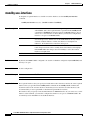
available for each command mode. Table 3-1 lists the most common command modes.
Table 3-1
Timesaver
Common Command Modes
Command Mode
Access Method
Router Prompt
Displayed
User EXEC
Log in.
Router>
Use the logout
command.
Privileged EXEC
From user EXEC mode,
enter the enable
command.
Router#
To exit to user EXEC
mode, use the disable,
exit, or logout
command.
Global configuration
From the privileged
EXEC mode, enter the
configure terminal
command.
Router (config)#
To exit to privileged
EXEC mode, use the
exit or end command,
or press Ctrl-z.
Interface configuration
From the global
configuration mode,
enter the interface type
number command, such
as interface serial 0/0.
Router (config-if)#
To exit to global
configuration mode, use
the exit command.
Exit Method
To exit directly to
privileged EXEC mode,
press Ctrl-z.
Each command mode restricts you to a subset of commands. If you are having trouble entering a
command, check the prompt, and enter the question mark (?) for a list of available commands. You
might be in the wrong command mode or using the wrong syntax.
In the following example, notice how the prompt changes after each command to indicate a new
command mode:
Router> enable
Password: <enable password>
Router# configure terminal
Router (config)# interface serial 0/0
Router (config-if)# line 0
Router (config-line)# controller t1 0
Router (config-controller)# exit
Router (config)# exit
Router#
%SYS-5-CONFIG_I: Configured from console by console
The last message is normal and does not indicate an error. Press Return to get the Router# prompt.
Cisco MWR 1900 Mobile Wireless Edge Router Software Configuration Guide
3-2
78-13983-04
Chapter 3
Cisco IOS Software Basics
Undoing a Command or Feature
Note
You can press Ctrl-z in any mode to immediately return to enable mode (Router#), instead of
entering exit, which returns you to the previous mode.
Undoing a Command or Feature
If you want to undo a command you entered or disable a feature, enter the keyword no before most
commands; for example, no ip routing.
Saving Configuration Changes
You need to enter the copy running-config startup-config command to save your configuration
changes to nonvolatile random-access memory (NVRAM), so the changes are not lost if there is a system
reload or power outage. For example:
Router# copy running-config startup-config
Building configuration...
It might take a minute or two to save the configuration to NVRAM. After the configuration has been
saved, the following appears:
[OK]
Router#
Where to Go Next
Now that you have learned some Cisco IOS software basics, you can begin to configure the router using
the CLI.
Remember that:
•
You can use the question mark (?) and arrow keys to help you enter commands.
•
Each command mode restricts you to a set of commands. If you have difficulty entering a command,
check the prompt and then enter the question mark (?) for a list of available commands. You might
be in the wrong command mode or using the wrong syntax.
•
To disable a feature, enter the keyword no before the command; for example, no ip routing.
•
You need to save your configuration changes to NVRAM so the changes are not lost if there is a
system reload or power outage.
Proceed to Chapter 4, “Configuring with the Command-Line Interface” to begin configuring the router.
Cisco MWR 1900 Mobile Wireless Edge Router Software Configuration Guide
78-13983-04
3-3
Chapter 3
Cisco IOS Software Basics
Where to Go Next
Cisco MWR 1900 Mobile Wireless Edge Router Software Configuration Guide
3-4
78-13983-04
C H A P T E R
4
Configuring with the Command-Line Interface
This chapter describes how to use the Cisco IOS software command-line interface (CLI) to configure the
following features of the MWR 1900:
•
Before You Begin, page 4-2
•
Verifying the Version of Cisco IOS Software, page 4-2
•
Configuring the Host Name and Password, page 4-2
•
Configuring Multilink Interfaces, page 4-7
•
Configuring Fast Ethernet Interfaces, page 4-4
•
Configuring Multilink Interfaces, page 4-7
•
Configuring T1 and E1 Interfaces, page 4-11
•
Configuring QoS Attributes, page 4-13
•
Configuring Redundancy, page 4-16
•
Saving Configuration Changes, page 4-18
•
Verifying the Configuration, page 4-18
•
Monitoring and Managing the MWR 1900, page 4-22
•
Where to Go Next, page 4-24
Follow the procedures in this chapter to configure the router manually or if you want to change the
configuration after you have run the setup command facility (described in Chapter 1, “First-Time
Configuration”).
This chapter describes how to configure features related to the use of the MWR 1900 in an IP-RAN. For
additional configuration topics, refer to the Cisco IOS configuration guide and command reference
publications. These publications are available on the Documentation CD-ROM that came with your
router, on the World Wide Web from Cisco’s home page, or you can order printed copies separately.
Note
If you skipped the previous chapter, Chapter 3, “Cisco IOS Software Basics,” and you have never
configured a Cisco router, go back to that chapter and read it now. The chapter contains important
information you need to successfully configure your router.
Cisco MWR 1900 Mobile Wireless Edge Router Software Configuration Guide
78-13983-04
4-1
Chapter 4
Configuring with the Command-Line Interface
Before You Begin
Before You Begin
Before you configure the MWR 1900, there are a few caveats of which you should be aware:
•
You cannot disable Cisco Express Forwarding (CEF) on the MWR 1900. Commands such as
no ip cef will display an error message “%Cannot disable CEF on this platform.” Some commands,
such as no ip route-cache cef, will not return an error message. However, CEF will not be disabled
regardless of whether an error message is displayed.
•
If you are using the MWR 1900 in a redundant configuration and are attaching the MWR 1900 to a
device that uses spanning tree, configure portfast on the device to avoid problems with HSRP at start
up.
•
If you are using the MWR 1900 in a redundant configuration, disable Extended Availability Drop
and Insert (EADI) capabilities on the router (using the disable-eadi global configuration command)
to avoid a double-termination scenario upon reboot. If the MWR 1900 is not being used in a
redundant configuration, and EADI is specifically required, re-enable EADI using the
no disable-eadi global configuration command.
•
In case of a tie in priority, HSRP uses the IP address to determine the active router. Therefore, you
should ensure that the order of the IP addresses of the E1/T1 interfaces of the active router
corresponds to the order of the IP addresses of the E1/T1 interfaces of the standby router.
Verifying the Version of Cisco IOS Software
The MWR 1900 requires Cisco IOS Release 12.2(8)MC2 or a later Cisco IOS Release 12.2 MC be
installed. To verify the version of Cisco IOS software, use the show version command.
The show version command displays the configuration of the system hardware, the software version, the
names and sources of configuration files, and the boot images.
Configuring the Host Name and Password
One of the first configuration tasks you might want to do is configure the host name and set an encrypted
password. Configuring a host name allows you to distinguish multiple Cisco routers from each other.
Setting an encrypted password allows you to prevent unauthorized configuration changes.
Step 1
Enter enable mode and enter the password.
You have entered enable mode when the prompt changes to Router#.
Router> enable
Password: <password>
Step 2
Enter global configuration mode.
Router# configure terminal
The prompt changes to Router(config)#.
Cisco MWR 1900 Mobile Wireless Edge Router Software Configuration Guide
4-2
78-13983-04
Chapter 4
Configuring with the Command-Line Interface
Configuring Loopback Interfaces
Step 3
Change the name of the router to a meaningful name.
Router(config)# hostname router_name
The prompt changes from “Router” to the user-configured hostname once this command is issued.
Step 4
Enter an enable secret password. This password provides access to privileged EXEC mode. When a user
types enable at the EXEC prompt ( Router> ), they must enter the enable secret password to access
configuration mode.
router_name(config)# enable secret password
Step 5
Enter line configuration mode to configure the console port. The prompt changes to
Router(config-line)#.
router_name(config)# line con 0
Step 6
Enter a timeout value of 0 to prevent the router’s EXEC facility from timing out if you do not type any
information on the console screen for an extended period.
router_name(config-line)# exec-timeout 0 0
Step 7
Exit to global configuration mode.
router_name(config-line)# exit
Configuring Loopback Interfaces
The loopback interface is a software-only, virtual interface that emulates an interface that is always up.
The interface-number is the number of the loopback interface that you want to create or configure. There
is no limit on the number of loopback interfaces you can create.
The multilink interface is a virtual interface, if you are not going to assign an explicit IP address to the
interface, you should create a loopback interface for the multilink interface to enable IP processing on
the interface.
In the case where the MWR 1900 is used in a redundant configuration, you must also configure loopback
interfaces for the health and revertive interfaces. The health interface monitors the status of the
redundant configuration so that the standby router can take over if there is a problem with the active
router. The revertive interface is required to ensure that the switchover takes place. We recommend that
you use 101 for the health interface and 102 for the revertive interface.
To configure a loopback interface, do the following beginning in global configuration mode:
Step 1
Create a loopback interface for each multilink interface:
Router(config)# interface loopback number
Router(config-if)# ip address ip_address subnet_mask
Note
Step 2
For the health and revertive interfaces, you do not need to assign an IP address.
Exit interface configuration mode:
Router(config-if)# exit
Cisco MWR 1900 Mobile Wireless Edge Router Software Configuration Guide
78-13983-04
4-3
Chapter 4
Configuring with the Command-Line Interface
Configuring Fast Ethernet Interfaces
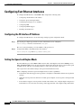
Configuring Fast Ethernet Interfaces
To configure the FE interface of the MWR 1900, complete the following tasks:
•
Configuring the FE Interface IP Address
•
Setting the Speed and Duplex Mode
•
Configuring Routing Protocol Attributes
•
Configuring PIM
•
Configuring HSRP Support
•
Enabling the FE Interface
Configuring the FE Interface IP Address
To configure the FE interface, do the following starting in global configuration mode:
Step 1
Specify the port adapter type and the location of the interface to be configured.
Router(config)# interface fastethernet slot/port
The slot is always 0 and the port is the number of the port (0 or 1).
Step 2
Assign an IP address and subnet mask to the interface.
Router(config-if)# ip address ip_address subnet_mask
Setting the Speed and Duplex Mode
The Fast Ethernet ports of the MWR 1900 can run in full or half duplex mode and at 100 Mbps or 10
Mbps. The MWR 1900 also has an auto-negotiation feature that allows the router to negotiate the speed
and duplex mode with the corresponding interface on the other end of the connection.
Auto negotiation is the default setting for the speed and transmission mode.
When configuring an interface speed and duplex mode, note these guidelines:
•
If both ends of the line support auto negotiation, we highly recommend the default auto negotiation
settings.
•
When the auto negotiation is turned on for either speed or duplex, it auto negotiates both speed and
duplex.
•
If one interface supports auto negotiation and the other end does not, configure duplex and speed on
both interfaces; do not use the auto setting on the supported side or the duplex setting will be half.
Cisco MWR 1900 Mobile Wireless Edge Router Software Configuration Guide
4-4
78-13983-04
Chapter 4
Configuring with the Command-Line Interface
Configuring Fast Ethernet Interfaces
To configure speed and duplex operation, do the following while still in interface configuration mode:
Step 1
Specify the duplex operation.
Router(config-if)# duplex [auto | half | full]
Step 2
Specify the speed.
Router(config-if)# speed [auto | 100 | 10]
Configuring Routing Protocol Attributes
When used in the CDMA IP-RAN solution, the MWR 1900 must be configured to support the OSPF
routing protocol. To configure OSPF routing protocol attributes, do the following while still in interface
configuration mode:
Step 1
Enable OSPF Message Digest 5 (MD5) authentication.
Router(config-if)# ip ospf message-digest-key key-id md5 key
Step 2
Specify the interval between hello packets that the Cisco IOS software sends on the interface.
Router(config-if)# ip ospf hello-interval seconds
Step 3
Set the interval at which hello packets must not be seen before neighbors declare the router down.
Router(config-if)# ip ospf dead-interval seconds
Configuring PIM
Because the MWR 1900 is used in a multicast PPP environment, you should configure the PIM mode of
the FE interface.
To configure the PIM mode, do the following while still in interface configuration mode:
Step 1
Enter the following command:
Router(config-if)# ip pim {sparse-mode | sparse-dense-mode | dense-mode [proxy-register
{list access-list | route-map map-name}]}
Cisco MWR 1900 Mobile Wireless Edge Router Software Configuration Guide
78-13983-04
4-5
Chapter 4
Configuring with the Command-Line Interface
Configuring Fast Ethernet Interfaces
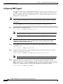
Configuring HSRP Support
In redundant configurations, the MWR 1900 uses HSRP to control the active and standby routers. To
use HSRP, you must configure the standby priority attributes and the IP address of the virtual router.
Priority is determined first by the configured priority value, and then by the IP address. In each case a
higher value is of greater priority.
Note
If you do not plan to use the MWR 1900 in a redundant configuration, do not configure HSRP support
and see Configuring Redundancy, page 4-16 for information about using the router in a stand-alone
environment.
To configure HSRP support, do the following while still in interface configuration mode:
Step 1
Specify the name of the standby group.
Router(config-if)# standby group name group-name
Note
Tips
Step 2
The standby group names must be “one” and “two.” For FE 0/0, the command must be
standby 1 name one. For FE 0/1, the command must be standby 2 name two.
If you omit the group-name or if you enter a group name that doesn’t begin with one or two, the
configuration will fail and there will be a mismatch in the information displayed by the show
redundancy and show standby commands.
Enable HSRP and assign an IP address to the virtual router. This address is the same for both the active
and standby routers.
Router(config-if)# standby group ip address
Step 3
Configure the time between hello packets and the time before other routers declare the active Hot
Standby or standby router to be down.
Router(config-if)# standby group timers [msec] hellotime [msec] holdtime
Note
Step 4
You must use 1 for the hello time and 3 for the hold time.
Indicate that the router can become the active router when its priority is higher than all other
HSRP-configured routers. Without preemption, a standby router will only transition to the active state if
HSRP “hello messages” cease. In the CDMA IP-RAN solution, there may be situations in which you want a
switchover to occur in the absence of a router or FE failure, therefore, preemption is required.
Router(config-if)# standby group preempt
Cisco MWR 1900 Mobile Wireless Edge Router Software Configuration Guide
4-6
78-13983-04
Chapter 4
Configuring with the Command-Line Interface
Configuring Multilink Interfaces
Step 5
Specify other interfaces on the router for the HSRP process to monitor in order to alter the HSRP
priority for a given group. When using the MWR 1900 router in the CDMA IP-RAN solution, you must
configure each FE interface to track the multilink interface, the loopback interfaces, and the other FE
interface.
Router(config-if)# standby group track multilinknumber decrement_value
Router(config-if)# standby group track loopbacknumber decrement_value
Router(config-if)# standby group track fastethernetnumber decrement_value
Note
Step 6
In redundant configurations, you should issue standby track commands for both the health
interface (loopback101) and the revertive interface (loopback102) as well as for the backhaul
interface (multilink1). The decrement values must be as follows: 10 for the multilink, FE,
and health interfaces; 5 for the revertive interface.
Specify a priority of 100.
Router(config-if)# standby group priority 100
Note
If you are using the MWR 1900 in a redundant configuration, you must also set the keepalives under
the FE interface to 1.
Router(config-if)# keepalive 1
Enabling the FE Interface
Once you have configured the FE interface, enable it by doing the following while still in interface
configuration mode:
Step 1
Enable the interface.
Router(config-if)# no shutdown
Configuring Multilink Interfaces
To configure the multilink interfaces, complete the following tasks:
•
Configuring Multilink PPP
•
Configuring IP Address Assignment
•
Configuring PPP Multiplexing
•
Configuring RTP/UDP Compression
•
Configuring Routing Protocol Attributes
•
Configuring PIM
Cisco MWR 1900 Mobile Wireless Edge Router Software Configuration Guide
78-13983-04
4-7
Chapter 4
Configuring with the Command-Line Interface
Configuring Multilink Interfaces
Configuring Multilink PPP
As higher-speed services are deployed, Multilink-PPP (MLP) provides a standardized method for
spreading traffic across multiple WAN links, while providing multivendor interoperability and
load-balancing on both inbound and outbound traffic.
A Multilink interface is a special virtual interface which represents a multilink PPP bundle. The
multilink interface serves to coordinate the configuration of the bundled link, and presents a single
object for the aggregate links. However, the individual PPP links that are aggregated together, must also
be configured. Therefore, to enable Multilink PPP on multiple serial interfaces, you need to first set up
the multilink interface, and then configure each of the serial interfaces and add them to the same
multilink interface.
The MWR 1900 router can support up to 4 T1 interfaces through the multilink interface.
To set up the multilink interface, do the following beginning in global configuration mode:
Step 1
Specify the multilink interface to be configured.
RPM-3(config)# interface multilink number
Step 2
Enable multilink PPP operation.
RPM-3(config-if)# ppp multilink
Step 3
Specify an identification number for the multilink interface.
RPM-3(config-if)# multilink-group group-number
Step 4
Enable IP processing on a the multilink interface without assigning an explicit IP address to the
interface.
RPM-3(config-if)# ip unnumbered loopback number
Where number is the number of the multilink loopback interface that you configured in Configuring
Loopback Interfaces.
Configuring IP Address Assignment
A point-to-point interface must be able to provide a remote node with its IP address through the IP
Control Protocol (IPCP) address negotiation process. The IP address can be obtained from a variety of
sources. The address can be configured through the command line, entered with an EXEC-level
command, provided by TACACS+ or the Dynamic Host Configuration Protocol (DHCP), or from a
locally administered pool.
IP address pooling uses a pool of IP addresses from which an incoming interface can provide an IP
address to a remote node through IPCP address negotiation process. IP address pooling also enhances
configuration flexibility by allowing multiple types of pooling to be active simultaneously.
Cisco MWR 1900 Mobile Wireless Edge Router Software Configuration Guide
4-8
78-13983-04
Chapter 4
Configuring with the Command-Line Interface
Configuring Multilink Interfaces
To configure IP address assignment, do the following do the following while still in multilink interface
configuration mode:
Step 1
Specify an IP address, an address from a specific IP address pool, or an address from the Dynamic Host
Configuration Protocol (DHCP) mechanism to be returned to a remote peer connecting to this interface:
RPM-3(config-if)# peer default ip address {ip-address | dhcp | pool [pool-name]}
Configuring PPP Multiplexing
To enable and control the multiplexing of PPP frames, do the following while still in multilink interface
configuration mode:
Step 1
Enable PPP multiplexing:
RPM-3(config-if)# ppp mux
Step 2
Specify the parameters of multiplexing.
To set the maximum time delay, enter:
RPM-3(config-if)# ppp mux delay integer
To set the maximum length of the subframe, enter:
RPM-3(config-if)# ppp mux subframe length integer
To set maximum length of the superframe, enter:
RPM-3(config-if)# ppp mux frame integer
To set the maximum number of subframes in a superframe, enter:
RPM-3(config-if)# ppp mux subframe count integer
To set the default PPP protocol ID, enter:
RPM-3(config-if)# ppp mux pid integer
Configuring RTP/UDP Compression
Enabling compression on both ends of a low-bandwidth serial link can greatly reduce the network
overhead if there is a lot of RTP traffic on that slow link. This compression is beneficial especially when
the RTP payload size is small (for example, compressed audio payloads of 20-50 bytes).
Before you can enable RTP header compression, you must configure a serial line that uses PPP
encapsulation.
Cisco MWR 1900 Mobile Wireless Edge Router Software Configuration Guide
78-13983-04
4-9
Chapter 4
Configuring with the Command-Line Interface
Configuring Multilink Interfaces
To configure RTP header compression, do the following while still in multilink interface configuration
mode:
Step 1
Enable RTP header compression for serial encapsulations:
RPM-3(config-if)# ip rtp header-compression
Step 2
By default, the software supports a total of 16 RTP header compression connections on an interface. To
change that number, enter the following command:
RPM-3(config-if)# ip rtp compression-connections number
Note
The MWR 1900 supports up to 600 RTP header compression connections on an interface.
Configuring Routing Protocol Attributes
When used in the CDMA IP-RAN solution, the multilink interface must be configured to support the
OSPF routing protocol.
To configure OSPF routing protocol attributes, do the following while still in interface configuration
mode:
Step 1
Enable OSPF Message Digest 5 (MD5) authentication:
RPM-3(config-if)# ip ospf message-digest-key key-id md5 key
Step 2
Specify the interval between hello packets that the Cisco IOS software sends on the interface:
RPM-3(config-if)# ip ospf hello-interval seconds
Step 3
Set the interval at which hello packets must not be seen before neighbors declare the router down:
RPM-3(config-if)# ip ospf dead-interval seconds
Configuring PIM
Because the MWR 1900 is used in a multicast PPP environment, you should configure the PIM mode of
the multilink interface.
To configure the PIM mode, do the following while still in interface configuration mode:
Step 1
Enter the following command:
RPM-3(config-if)# ip pim {sparse-mode | sparse-dense-mode | dense-mode [proxy-register
{list access-list | route-map map-name}]}
Cisco MWR 1900 Mobile Wireless Edge Router Software Configuration Guide
4-10
78-13983-04
Chapter 4
Configuring with the Command-Line Interface
Configuring T1 and E1 Interfaces
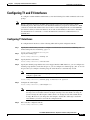
Configuring T1 and E1 Interfaces
To configure a T1/E1 multiflex trunk interface, enter the following Cisco IOS commands at the router
prompt.
Note
Before you begin, disconnect all WAN cables from the router to keep it from trying to run the
AutoInstall process. The router tries to run AutoInstall whenever you power it on if there is a WAN
connection on both ends and the router does not have a valid configuration file stored in NVRAM
(for instance, when you add a new interface). It can take several minutes for the router to determine
that AutoInstall is not connected to a remote Transmission Control Protocol/Internet Protocol
(TCP/IP) host.
Configuring T1 Interfaces
To configure the T1 interfaces, do the following while still in global configuration mode:
Step 1
Specify the controller that you want to configure. For information about interface numbering, see
Understanding Interface Numbering, page 2-1.
Router(config)# controller t1 slot/port
Step 2
Specify the framing type.
Router(config-controller)# framing esf
Step 3
Specify the line code format.
Router(config-controller)# linecode b8zs
Step 4
Specify the channel group and time slots to be mapped. For the VWIC interfaces, you can configure two
channel-groups (0 and 1) on the first T1 port or you can configure one channel-group ( 0 or 1) on each
T1 port. Once you configure a channel group, the serial interface is automatically created.
Note
The default speed of the channel group is 56. To get full DS0/DS1 bandwidth, you must
configure a speed of 64.
Router(config-controller)# channel-group 0 timeslots 1-24 speed 64
Step 5
Configure the cable length.
Router(config-controller)# cablelength feet
Note
Step 6
Although you can specify a cable length from 0 to 450 feet, the hardware only recognizes
two ranges: 0 to 49 and 50 to 450. For example, entering 35 feet uses the 0 to 49 range. If
you later change the cable length to 40 feet, there is no change because 40 is within the 0 to
49 range. However, if you change the cable length to 50, the 50 to 450 range is used. The
actual number you enter is stored in the configuration file.
Exit controller configuration mode.
Router(config-controller)# exit
Cisco MWR 1900 Mobile Wireless Edge Router Software Configuration Guide
78-13983-04
4-11
Chapter 4
Configuring with the Command-Line Interface
Configuring T1 and E1 Interfaces
Step 7
Configure the serial interface. Specify the T1 slot (always 0), port number, and channel group.
Router(config)# interface serial slot/port:0
Step 8
Assign an IP address and subnet mask to the interface. If the interface is a member of a Multilink bundle
(MLPPP), then skip this step.
Router(config-if)# ip address ip_address subnet_mask
Step 9
Before you can enable RTP header compression, you must have configured a serial line that uses PPP
encapsulation. Enter the following command to configure PPP encapsulation.
Router(config-if)# encapsulation ppp
Step 10
Set the carrier delay for the serial interface.
Router(config-if)# carrier-delay number
Step 11
Return to Step 1 to configure the second port on the VWIC and the ports on any additional VWICs.
Step 12
Exit to global configuration mode.
Router(config-if)# exit
Configuring E1 Interfaces
To configure the E1 interfaces, do the following while still in global configuration mode:
Step 1
Specify the controller that you want to configure. Controller E1 0/0 maps to the first port of the VWIC
in slot 0. Controller E1 0/1 maps to the second port of the VWIC in slot 0.
Router(config)# controller e1 slot/port
Step 2
Specify the framing type.
Router(config-controller)# framing crc4
Step 3
Specify the line code format.
Router(config-controller)# linecode hdb3
Step 4
Specify the channel group and time slots to be mapped. For the VWIC interfaces, you can configure
channel-group 0 and 1 on one port or one channel-group (either 0 or 1) on each port. Once you configure
a channel group, the serial interface is automatically created.
Router(config-controller)# channel-group 0 timeslots 1-24 speed 64
Note
The default speed of the channel group is 56. To get full DS0/DS1 bandwidth, you must
configure a speed of 64.
Cisco MWR 1900 Mobile Wireless Edge Router Software Configuration Guide
4-12
78-13983-04
Chapter 4
Configuring with the Command-Line Interface
Configuring QoS Attributes
Step 5
Configure the cable length.
Router(config-controller)# cablelength feet
Note
Step 6
Although you can specify a cable length from 0 to 450 feet, the hardware only recognizes
two ranges: 0 to 49 and 50 to 450. For example, entering 35 feet uses the 0 to 49 range. If
you later change the cable length to 40 feet, there is no change because 40 is within the 0 to
49 range. However, if you change the cable length to 50, the 50 to 450 range is used. The
actual number you enter is stored in the configuration file.
Exit controller configuration mode.
Router(config-controller)# exit
Step 7
Configure the serial interface. Specify the E1 slot (always 0), port number, and channel group.
Router(config)# interface serial slot/port:0
Step 8
Assign an IP address and subnet mask to the interface. If the interface is a member of a Multilink bundle
(MLPPP), then skip this step.
Router(config-if)# ip address ip_address subnet_mask
Step 9
Before you can enable RTP header compression, you must have configured a serial line that uses PPP
encapsulation. Enter the following command to configure PPP encapsulation.
Router(config-if)# encapsulation ppp
Step 10
Set the carrier delay for the serial interface.
Router(config-if)# carrier-delay number
Step 11
Return to Step 1 to configure the second port on the VWIC and the ports on any additional VWICs.
Step 12
Exit to global configuration mode.
Router(config-if)# exit
Configuring QoS Attributes
To use QoS on the MWR 1900 router, you must first create a class map. The class map defines the
criteria that a packet must match to be placed in that class. Once you have created a class map, the router
can recognize packets that are subject to QoS. You must then tell the router the action to take on those
packets by creating a policy map.Once you have completed the creation of a QoS boilerplate, you can
assign it to an interface.
Note
The QoS functionality of the MWR 1900 router is built on the same code as the Cisco 10000 ESR
(with some exceptions). For more information about the QoS feature, see “Configuring Quality of
Service” (http://www.cisco.com/univercd/cc/td/doc/product/aggr/10000/10ksw/qosos.htm) and the
“Cisco 10000 Series ESR Quality of Service” feature module
(http://www.cisco.com/univercd/cc/td/doc/product/aggr/10000/10kfm/fm_qos.htm), as well as the
“Cisco IOS Quality of Service Solutions Configuration Guide” and the “Cisco IOS Quality of
Service Solutions Command Reference.”
Cisco MWR 1900 Mobile Wireless Edge Router Software Configuration Guide
78-13983-04
4-13
Chapter 4
Configuring with the Command-Line Interface
Configuring QoS Attributes
Creating a Class Map
For each class map that you want to create, do the following in global configuration mode:
Step 1
Assign a name to your class map.
Router(config)# class-map [match-all | match-any] class_name
Where match-any means a single match rule is sufficient for class membership and match-all means
only those packets that have all the attributes you specify are part of the class.
When you enter the class-map command, you are placed in class map configuration mode.
Step 2
Describe the characteristics of the packets that are subject to QoS using one or more of the following.
Router(config-cmap)# match access-group number
Router(config-cmap)# match ip dscp number
Router(config-cmap)# match ip precedence number
Router(config-cmap)# match input-interface interface-name
•
match access-group specifies access control list (ACL) that a packet must match.
•
match ip dscp specifies the IP differentiated service code point (DSCP) that a packet must match.
•
match ip precedence specifies the precedence values (0-7) that a packet must match.
•
match input-interface specifies the name of the input interface used as a match criterion.
For more information about these commands, see the “Cisco IOS Quality of Service Solutions Command
Reference.”
Step 3
Exit class map configuration mode.
Router(config-cmap)# exit
Creating a Policy Map
To create a policy map, do the following in global configuration mode:
Step 1
Assign a name to your policy map.
Router(config)# policy-map policy_name
When you enter the policy-map command, you are placed in policy map configuration mode.
Step 2
Associate the policy map with a class map.
Router(config-pmap)# class class_name
Specify the same class_name as you did in Step 1 of Creating a Class Map. When you enter the class
command, you are placed in class submode of the policy-map configuration mode.
Cisco MWR 1900 Mobile Wireless Edge Router Software Configuration Guide
4-14
78-13983-04
Chapter 4
Configuring with the Command-Line Interface
Configuring QoS Attributes
Step 3
Describe the QoS actions you want the router to perform when the router encounters a packet that has
the characteristics described by the class map. Use one or more of the following commands:
Router(config-pmap-c)# priority percent number
Router(config-pmap-c)# bandwidth percent number
Router(config-pmap-c)# queue-limit number
Router(config-pmap-c)# priority rate-in-kbps
Router(config-pmap-c)# shape {average | peak} cir [bc] [be]
Router(config-pmap-c)# shape max-buffers number-of-buffers
•
priority percent gives priority to a class of traffic belonging to a policy map and specifies that a
certain percentage of the available bandwidth should be reserved for this class.
•
bandwidth percent specifies the bandwidth allocated for a class belonging to a policy map.
•
queue-limit specifies the maximum number of packets the queue can hold for a class policy
configured in a policy map.
•
priority enables low-latency priority queuing, which allows you to assign a specified share of the
link bandwidth to one queue that receives priority over all others. Low-latency priority queueing
minimizes the packet-delay variance for delay-sensitive traffic, such as live voice and video.
•
shape and shape max-buffers are used with class-based weighted fair queuing (CB-WFQ), which
allows you to control the traffic going out an interface in order to match its transmission to the speed
of the remote target interface.
Note
The bandwidth percent and priority percent commands cannot be used in the same
class, within the same policy map. These commands can be used together in the same
policy map, however.
For more information about these commands, see the “Cisco IOS Quality of Service Solutions Command
Reference.”
Step 4
To configure the Class-Based Packet Marking feature, you must configure either an IP Precedence value
or an IP differentiated services code point (DSCP). The QOS group is optional.
Router(config-pmap-c)# set ip dscp ip-dscp-value
Router(config-pmap-c)# set ip precedence ip-precedence-value
Router(config-pmap-c)# set qos-group qos-group-value
•
set ip dscp marks a packet by setting the IP DSCP value.
•
set ip precedence marks a packet by setting the IP Precedence bits in the ToS byte.
•
set qos-group associates a local QoS group value with a packet.
For more information about these commands, see the “Cisco IOS Quality of Service Solutions Command
Reference.”
Cisco MWR 1900 Mobile Wireless Edge Router Software Configuration Guide
78-13983-04
4-15
Chapter 4
Configuring with the Command-Line Interface
Configuring Redundancy
Step 5
Repeat Step 2 and Step 3 for each class map.
Step 6
Exit policy map configuration mode.
Router(config-pmap-c)# exit
Router(config-pmap)# exit
Assigning a QoS Boilerplate to an Interface
To assign a QoS boilerplate to a multilink interface, do the following in global configuration mode.
Step 1
Access the multilink interface configuration mode.
Router(config)# interface multilink number
Step 2
Assign the QoS boilerplate to the multilink interface.
Router(config-if)# service-policy output policy_name
Configuring Redundancy
The MWR 1900 router can be used in either a redundant configuration (preferable) or as a stand-alone
device.
Note
To implement redundancy, you must also configure HSRP under the Fast Ethernet interface. See the
“Configuring HSRP Support” section on page 4-6 for more information.
Redundant MWR 1900s
For redundancy, the MWR 1900 router makes use of the existing HSRP feature. However, additional
controls are needed for the MWR 1900. In a redundant configuration, the MWR 1900 router must track
the status of the health and revertive loopback interfaces as well as the backhaul interface.
To configure an MWR 1900 for use in a redundant configuration, do the following starting in global
configuration mode:
Step 1
Disable EADI capabilities on the router.
Router(config)# disable-eadi
Step 2
Enter redundancy mode.
Router(config)# redundancy
Step 3
Enter the y-cable mode.
Router(config-r)# mode y-cable
Cisco MWR 1900 Mobile Wireless Edge Router Software Configuration Guide
4-16
78-13983-04
Chapter 4
Configuring with the Command-Line Interface
Configuring Redundancy
Step 4
Specify the loopback interface to be used to monitor the health of the router and for revertive purposes.
Router(config-r-y)# standby use-interface interface health
Router(config-r-y)# standby use-interface interface revertive
Note
Step 5
The interfaces that you specify for the health and revertive interfaces should match those that
you configured and tracked in Configuring Loopback Interfaces. (We recommend you use
loopback101 for the health and loopback102 for the revertive interface).
Specify the interface to be used for backhauling.
Router(config-r-y)# standby use-interface interface backhaul
Note
Step 6
The interface that you specify for the backhaul must be an MLPPP interface. If you want to
use a serial interface as the backhaul, you must first configure that interface to be part of an
MLPPP bundle. The interface that you specify for the backhaul interface should match one
of those that you configured and tracked in Configuring Loopback Interfaces.
Exit y-mode configuration mode.
Router(config-r-y)# exit
To verify the status of the relays on an MWR 1900 router, use the show controllers command.
Stand-Alone MWR 1900
The MWR 1900 router has relays that work with a special “y” cable for redundancy and are controlled
by HSRP. You can, however, use the MWR 1900 as a stand-alone device. If you choose not to use the
MWR 1900 in a redundant configuration, you should not configure HSRP and you must control the
relays of the VWIC card manually.
To manually set the relays to open or closed, do the following starting in global configuration mode:
Step 1
Enter redundancy mode.
Router(config)# redundancy
Step 2
Enter the y-cable mode.
Router(config-r)# mode y-cable
Step 3
Specify that the router is to be used as a stand-alone device. This command closes the relays.
Router(config-r-y)# standalone
Step 4
Exit y-mode configuration mode.
Router(config-r-y)# exit
To verify the status of the relays on an MWR 1900 router, use the show controllers command.
Cisco MWR 1900 Mobile Wireless Edge Router Software Configuration Guide
78-13983-04
4-17
Chapter 4
Configuring with the Command-Line Interface
Saving Configuration Changes
Saving Configuration Changes
To prevent the loss of the router configuration, save it to non-volatile random access memory
(NVRAM). To save the configuration to NVRAM, do the following:
Step 1
Exit configuration mode.
Router(config)# exit
Note
Step 2
You can press Ctrl-z in any mode to immediately return to enable mode (Router#), instead
of entering exit, which returns you to the previous mode.
Save the configuration changes to NVRAM so that they are not lost during resets, power cycles, or power
outages.
Router# copy running-config startup-config
Verifying the Configuration
To verify the configuration of the MWR 1900, enter the following command:
MWR1900-1#show running-config
hostname MWR1900-1
!
boot system slot0:mwr-1900-boot
!
! description Loopback IP for O & M
!
interface loopback 0
ip address 10.1.170.3 255.255.255.255
!
! description Loopback IP for IP Unnumbered
!
interface loopback 2
ip address 192.168.170.2 255.255.255.255
!
interface loopback101
description Health Loopback Interface
no ip address
!
interface loopback102
description Revertive Loopback Interface
no ip address
!
enable password cisco
!
memory-size iomem 25
!
disable-eadi
!
redundancy
mode y-cable
standby use-interface Loopback101 health
Cisco MWR 1900 Mobile Wireless Edge Router Software Configuration Guide
4-18
78-13983-04
Chapter 4
Configuring with the Command-Line Interface
Verifying the Configuration
standby use-interface Loopback102 revertive
standby use-interface Multilink2 backhaul
!
controller T1 0/0
framing esf
cablelength short 133ft
clock source internal
linecode b8zs
channel-group 0 timeslots 1-1 speed 64
channel-group 1 timeslots 2-24 speed 64
!
controller T1 0/1
framing esf
clock source internal
linecode b8zs
cablelength short 133ft
!
!
class-map match-all class1_fch
match ip dscp cs5
class-map match-all class2_sch
match ip dscp cs4
class-map match-any class3_paging_ospf
match ip dscp cs3
match access-group 101
!
policy-map llq-policy
class class1_fch
priority percent 68
class class2_sch
bandwidth percent 20
queue-limit 128
class class3_paging_ospf
bandwidth percent 2
queue-limit 128
class class-default
queue-limit 512
!
ip dhcp excluded-address 192.168.146.1 192.168.146.3
ip dhcp ping packets 0
!
ip dhcp pool pbts
network 192.168.146.0 255.255.255.0
bootfile CENOMIbts.img
next-server OMCR-IPaddr
option 43 ascii "Logical-IPaddr CENOMI-IPaddr another-IPaddr SpanMapping"
default-router 192.168.146.3
dns-server OMCR-IPaddr
lease 0 0 1
!
ip routing
ip subnet-zero
ip classless
ip multicast-routing
ip tftp source-interface Loopback 0
cdp run
!
! Setup sys logging to OMCIP-CW2000
!
logging on
logging buffered 4
logging cw4mw
logging trap 5
logging source-interface Loopback0
Cisco MWR 1900 Mobile Wireless Edge Router Software Configuration Guide
78-13983-04
4-19
Chapter 4
Configuring with the Command-Line Interface
Verifying the Configuration
!
! Setup SNMP
!
snmp community private rw
snmp community public ro
snmp-server enable traps
snmp-server trap-source Loopback 0
snmp-server host cw4mw public
!
! Setup useful aliases
!
ip host omcr OMCR_ip_address
ip host omcip OMCIP_ip_address
ip host cw4mw CW4MW_ip_address
ip host btsha-other-0 192.168.146.2
ip host btsha-other-1 192.168.147.2
!
!interface Multilink1
description Backhaul Interface
ip unnumbered loopback 2
cdp enable
ppp multilink
ip ospf hello-interval 1
ip ospf dead-interval 3
ip ospf message-digest-key 1 md5 mymd5pw
!
interface Multilink2
description
ip unnumbered loopback 2
ip mroute-cache
ip mtu 256
cdp enable
ppp multilink
ip rtp header-compression
ip rtp compression-connections 700
ppp mux
ppp mux subframe length 64
ppp mux subrame count 15
ppp mux frame 256
ppp mux delay 800
ppp mux pid 0x2067
ip ospf hello-interval 1
ip ospf dead-interval 3
ip ospf message-digest-key 1 md5 mymd5pw
ip pim sparse-mode
ip pim version 2
service-policy output llq-policy
!
interface FastEthernet0/0
ip address 192.168.146.1 255.255.255.0
no ip proxy-arp
no ip mroute-cache
keepalive 1
full-duplex
speed 100
ntp broadcast version 3
standby 1 ip 192.168.146.3
standby 1 timers 1 3
standby 1 priority 100
standby 1 preempt
standby 1 name one
standby 1 track FastEthernet0/1 10
standby 1 track Loopback101 10
standby 1 track Loopback102 5
Cisco MWR 1900 Mobile Wireless Edge Router Software Configuration Guide
4-20
78-13983-04
Chapter 4
Configuring with the Command-Line Interface
Verifying the Configuration
standby 1 track Multilink2 10
ip ospf hello-interval 1
ip ospf dead-interval 3
ip ospf message-digest-key 1 md5 mymd5pw
ip pim sparse-mode
ip pim version 2
ip pim query-interval 2
interface FastEthernet0/1
ip address 192.168.147.1 255.255.255.0
standby 2 timers 1 3
standby 2 preempt
standby 2 priority 100
standby 2 ip 192.168.147.3
standby 2 name two
standby 2 track Fa0/0 10
standby 2 track Multilink2 10
standby 2 track Loopback101 10
standby 2 track Loopback102 5
keepalive 1
speed 100
full-duplex
ntp broadcast version 3
ip ospf hello-interval 1
ip ospf dead-interval 3
ip ospf message-digest-key 1 md5 mymd5pw
ip pim sparse-mode
ip pim version 2
ip pim query-interval 2
!
!
!interface Serial0/0:0
no ip address
encapsulation ppp
keepalive 1
ppp multilink
multilink-group 1
!
interface Serial0/1:0
no ip address
encapsulation ppp
keepalive 1
ppp multilink
multilink-group 2
!
router ospf 1
log-adjacency-changes
area 2 nssa
area 2 authentication message-digest
auto-cost reference-bandwidth 10240
timers spf 1 10
redistribute ospf 2 metric-type 1 subnets
redistribute static metric-type 1 subnets
network 192.168.170.2 0.0.0.3 area 2
distribute-list 10 out
distance ospf external 125
summary-address area-51-prefix mask
!
router ospf 2
log-adjacency-changes
auto-cost reference-bandwidth 10240
area 51 authentication message-digest
timers spf 1 10
redistribute ospf 1 metric-type 1 subnets tag 202051
Cisco MWR 1900 Mobile Wireless Edge Router Software Configuration Guide
78-13983-04
4-21
Chapter 4
Configuring with the Command-Line Interface
Monitoring and Managing the MWR 1900
network 192.168.146.0 0.0.0.255 area 51
network 192.168.147.0 0.0.0.255 area 51
network 10.0.0.0 0.255.255.255 area 51
default-information originate metric 100 metric-type 1
distribute-list 11 out
distance 120
!
ip route 64.102.16.25 255.255.255.255 FastEthernet0/0
ip route 64.102.16.25 255.255.255.255 192.168.1.10
!
Notes
•
Keepalives must be set for all Ethernet interfaces to ensure proper redundant behavior. A keepalive
value of 1 has been selected for maximum responsiveness.
•
Configuring no ip proxy-arp is helpful to avoid confusion with routes and ARP caches.
•
In a redundant configuration, both MWR 1900s share a common IP address for their Multilink
interface.
Monitoring and Managing the MWR 1900
You can use Cisco’s network management applications, such as CiscoWorks2000 for Mobile Wireless
(CW4MW), to monitor and manage aspects of the MWR 1900.
To enable remote network management of the MWR 1900, do the following:
Step 1
At the privileged prompt, enter the following command to access configuration mode:
Router# configure terminal
Enter configuration commands, one per line.
Router(config)#
Step 2
End with CNTL/Z.
At the configuration prompt, enter the following command to assign a host name to each of the network
management workstations:
Router(config)# ip host hostname ip_address
Where hostname is the name assigned to the Operations and Maintenance (O&M) workstation and
ip_address is the address of the network management workstation.
Step 3
Enter the following commands to create a loopback interface for O&M:
Router(config)# interface loopback number
Router(config-if)# ip address ip_address subnet_mask
Step 4
Exit interface configuration mode:
Router(config-if)# exit
Step 5
At the configuration prompt, enter the following command to specify the recipient of a Simple Network
Management Protocol (SNMP) notification operation:
Router(config)# snmp-server host hostname [traps | informs] [version {1 | 2c | 3 [auth |
noauth | priv]}] community-string [udp-port port] [notification-type]
Where hostname is the name assigned to the CW4MW workstation with the ip host command in Step 2.
Cisco MWR 1900 Mobile Wireless Edge Router Software Configuration Guide
4-22
78-13983-04
Chapter 4
Configuring with the Command-Line Interface
Monitoring and Managing the MWR 1900
Step 6
Enter the following commands to specify the public and private SNMP community names:
Router(config)# snmp-server community public RO
Router(config)# snmp-server community private RW
Step 7
Enter the following command to enable the sending of SNMP traps:
Router(config)# snmp-server enable traps
Step 8
Enter the following command to specify the loopback interface from which SNMP traps should
originate:
Router(config)# snmp-server trap-source loopback number
Where number is the number of the loopback interface you configured for the O&M in Step 3.
Step 9
At the configuration prompt, press Ctrl-Z to exit configuration mode.
Step 10
Write the new configuration to nonvolatile memory as follows:
Router# copy running-config startup-config
Show Commands for Monitoring the MWR 1900
To monitor and maintain the MWR 1900 router (including the multilink, VWIC, and FE interfaces) and
to view information about the PPP mux and header compression configuration, use the following
commands:
Command
Purpose
show ip rtp header-compression
Displays RTP header compression statistics.
show interface fastethernet slot/port
Displays the status of the FE interface.
show ppp multilink
Displays MLP and multilink bundle information.
show ppp multilink interface number
Displays multilink information for the specified
interface.
show ppp mux interface interface
Displays statistics for PPP frames that have passed
through a given multilink interface.
show controllers fastethernet slot/port
Displays information about initialization block,
transmit ring, receive ring and errors for the Fast
Ethernet controller chip.
show controllers t1
Displays information about the cable length, framing,
firmware, and errors associated with the T1. With the
MWR 1900, this command also displays the status of
the relays on the VWIC.
show redundancy
Displays current redundant setting and recent
changes in state.
show standby
Displays HSRP configuration information.
clear counters fastethernet slot/port
Clears interface counters.
clear ppp mux interface
Clears the PPP mux counters on the specified
interface.
clear ip rtp header-compression
Clears RTP header compression structures and
statistics.
Cisco MWR 1900 Mobile Wireless Edge Router Software Configuration Guide
78-13983-04
4-23
Chapter 4
Configuring with the Command-Line Interface
Where to Go Next
Command
Purpose
show controllers
Displays all network modules and their interfaces.
Displays the status of the VWIC relays when a VWIC
is installed.
show interface type slot/port
Displays the configuration and status of the specified
interface.
show protocols
Displays the protocols configured for the router and
the individual interfaces.
Where to Go Next
At this point you can proceed to the following:
•
The Cisco IOS software configuration guide and command reference publications for more
advanced configuration topics. These publications are available on the Documentation CD-ROM
that came with your router, on the World Wide Web from Cisco’s home page, or you can order
printed copies.
•
The System Error Messages and Debug Command Reference publications for troubleshooting
information
Cisco MWR 1900 Mobile Wireless Edge Router Software Configuration Guide
4-24
78-13983-04
C H A P T E R
5
Command Reference
This chapter contains information about commands that were introduced specifically in support of the
MWR 1900:
The following commands have been added or changed with this release:
•
clear ppp mux
•
mode y-cable
•
ppp mux
•
ppp mux delay
•
ppp mux frame
•
ppp mux pid
•
ppp mux subframe length
•
ppp mux subframe count
•
redundancy
•
show ppp mux
•
show redundancy
•
standalone
•
standby use-interface
The following commands were not altered but have been included for your convenience:
•
clear ip rtp header-compression
•
ip rtp compression-connections
•
ip rtp header-compression
•
show ip rtp header-compression
Cisco MWR 1900 Mobile Wireless Edge Router Software Configuration Guide
78-13983-04
5-1
Chapter 5
Command Reference
clear ip rtp header-compression
clear ip rtp header-compression
To clear Real-Time Transport Protocol (RTP) header compression structures and statistics, use the clear
ip rtp header-compression EXEC command.
clear ip rtp header-compression [type number]
Syntax Description
type number
Command Modes
EXEC
Command History
Release
Modification
11.3
This command was introduced.
(Optional) Interface type and number.
Usage Guidelines
If this command is used without an interface type and number, it clears all RTP header compression
structures and statistics.
Examples
The following example clears RTP header compression structures and statistics for multilink interface 1:
clear ip rtp header-compression multilink1
Related Commands
Command
Description
ip rtp header-compression
Enables RTP header compression.
Cisco MWR 1900 Mobile Wireless Edge Router Software Configuration Guide
5-2
78-13983-04
Chapter 5
Command Reference
clear ppp mux
clear ppp mux
To clear PPP mux statistics, use the clear ppp mux EXEC command.
clear ppp mux [interface interface]
Syntax Description
interface
Defaults
If no interface is specified, statistics for all multilink and serial interfaces are cleared.
Command Modes
EXEC
Command History
Release
Modification
12.2(8)MC2
This command was introduced.
(Optional) The identifier of the multilink or serial interface for which you
want to clear counters.
Usage Guidelines
None
Examples
The following example clears PPP mux statistics for multilink interface 1:
clear ppp mux interface multilink1
Related Commands
Command
Description
show ppp mux
Displays PPP mux counters for the specified multilink interface.
Cisco MWR 1900 Mobile Wireless Edge Router Software Configuration Guide
78-13983-04
5-3
Chapter 5
Command Reference
ip rtp compression-connections
ip rtp compression-connections
To specify the total number of Real-Time Transport Protocol (RTP) header compression connections
that can exist on an interface, use the ip rtp compression-connections interface configuration
command. To restore the default value, use the no form of this command.
ip rtp compression-connections number
no ip rtp compression-connections
Syntax Description
number
Defaults
16 connections
Command Modes
Interface configuration
Command History
Release
Modification
11.3
This command was introduced.
12.0(7)T
For PPP and High-Level Data Link Control (HDLC) encapsulation, the
maximum number of connections increased from 256 to 1000.
Number of RTP header compression connections the cache supports, in the
range from 3 to 600. The default is 16 connections.
For Frame Relay encapsulation, the maximum number of connections
increased to 256. The maximum value for Frame Relay is fixed, not
configurable.
Examples
12.1(4)E
This command was supported on Cisco 7100 series routers.
12.2(8)MC2
The upper limit for the MWR 1900 is set at 600.
The following example changes the number of RTP header compression connections supported to 150:
interface serial 0
encapsulation ppp
ip rtp header-compression
ip rtp compression-connections 150
Related Commands
Command
Description
ip rtp header-compression
Enables RTP header compression.
show ip rtp
header-compression
Displays RTP header compression statistics.
Cisco MWR 1900 Mobile Wireless Edge Router Software Configuration Guide
5-4
78-13983-04
Chapter 5
Command Reference
ip rtp header-compression
ip rtp header-compression
To enable Real-Time Transport Protocol (RTP) header compression, use the ip rtp
header-compression interface configuration command. To disable RTP header compression, use the no
form of this command.
ip rtp header-compression [passive]
no ip rtp header-compression
Syntax Description
passive
Defaults
Disabled
Command Modes
Interface configuration
Command History
Release
Modification
11.3
This command was introduced.
Usage Guidelines
(Optional) Compresses outgoing RTP packets only if incoming RTP packets
on the same interface are compressed. This option is not applicable on PPP
links.
If you use this command without the passive keyword, the software compresses all RTP traffic.
You can compress IP/UDP/RTP headers and IP/UDP headers to reduce the size of your packets.
Compressing headers is especially useful for RTP, because RTP payload size can be as small as 20 bytes,
and the uncompressed header is 40 bytes.
RTP header compression is supported on serial lines using PPP encapsulation. You must enable
compression on both ends of a serial connection.
Examples
The following example enables RTP header compression on fast ethernet interface 1 and limits the
number of RTP header compression connections to 10:
interface serial 0
encapsulation ppp
ip rtp header-compression
ip rtp compression-connections 10
Cisco MWR 1900 Mobile Wireless Edge Router Software Configuration Guide
78-13983-04
5-5
Chapter 5
Command Reference
ip rtp header-compression
Related Commands
Command
Description
clear ip rtp
header-compression
Clears RTP header compression structures and statistics.
ip rtp
compression-connections
Specifies the total number of RTP header compression connections
that can exist on an interface.
show ip rtp
header-compression
Displays RTP header compression statistics.
Cisco MWR 1900 Mobile Wireless Edge Router Software Configuration Guide
5-6
78-13983-04
Chapter 5
Command Reference
mode y-cable
mode y-cable
To access the command mode that allows you to manually control the relays on the VWIC card, use the
mode y-cable command.
mode y-cable
Syntax Description
This command has no parameters, it invokes the y-cable mode.
Defaults
There are no default settings or behaviors.
Command Modes
Redundancy configuration
Command History
Release
Modification
12.2(8)MC2
This command was introduced.
Examples
The following example enables y-cable mode.
mode y-cable
Related Commands
Command
Description
standalone
Indicates whether the MWR 1900 router is being used as a standalone
device and manually sets the relays.
standby use-interface
Designates a loopback interface as a health or revertive interface.
redundancy
Invoked redundancy mode.
Cisco MWR 1900 Mobile Wireless Edge Router Software Configuration Guide
78-13983-04
5-7
Chapter 5
Command Reference
ppp mux
ppp mux
To enable PPP multiplexing/demultiplexing, use the ppp mux command in interface configuration
mode. To disable PPP multiplexing/demultiplexing, use the no form of this command.
ppp mux
no ppp mux
Syntax Description
This command has no parameters.
Defaults
PPP multiplexing/demultiplexing is disabled by default.
Command Modes
Interface configuration
Command History
Release
Modification
12.2(8)MC2
This command was introduced.
Examples
The following example enables PPP multiplexing/demultiplexing.
ppp mux
Related Commands
Command
Description
ppp mux delay
Sets the maximum delay.
ppp mux frame
Sets the maximum length of the PPP superframe.
ppp mux pid
Sets the default PPP protocol ID.
ppp mux subframe count
Sets the maximum number of subframes in a superframe.
ppp mux subframe length
Sets the maximum length of the PPP subframe.
show ppp mux
Displays PPP mux counters for the specified multilink interface.
Cisco MWR 1900 Mobile Wireless Edge Router Software Configuration Guide
5-8
78-13983-04
Chapter 5
Command Reference
ppp mux delay
ppp mux delay
To set the maximum time the processor can wait before sending a superframe, use the ppp mux delay
command in interface configuration mode. To set the maximum delay to the default, use the no form of
this command.
ppp mux delay integer
no ppp mux delay
Syntax Description
integer
Defaults
The default maximum delay is 0, which indicates that a superframe will be sent when the transmit queue
is full.
Command Modes
Interface configuration
Command History
Release
Modification
12.2(8)MC2
This command was introduced.
The maximum number of microseconds that the processor can wait before
sending out a PPP superframe. Possible values are 0 through 4000000
microseconds.
Usage Guidelines
To use this command, you must first enable PPP multiplexing/demultiplexing.
Examples
The following example sets the maximum delay to 5 microseconds.
ppp mux delay 5
Related Commands
Command
Description
ppp mux
Enables PPP multiplexing/demultiplexing
ppp mux frame
Sets the maximum length of the PPP superframe.
ppp mux pid
Sets the default PPP protocol ID.
ppp mux subframe count
Sets the maximum number of subframes in a superframe.
ppp mux subframe length
Sets the maximum length of the PPP subframe.
show ppp mux
Displays PPP mux counters for the specified multilink interface.
Cisco MWR 1900 Mobile Wireless Edge Router Software Configuration Guide
78-13983-04
5-9
Chapter 5
Command Reference
ppp mux frame
ppp mux frame
To set the maximum length (in bytes) of the PPP superframes, use the ppp mux frame command in
interface configuration mode. To set the maximum length to the default, use the no form of this
command.
ppp mux frame integer
no ppp mux frame
Syntax Description
integer
Defaults
The default maximum length is 197.
Command Modes
Interface configuration
Command History
Release
Modification
12.2(8)MC2
This command was introduced.
The maximum number of bytes in any multiplexed PPP superframe. Possible
values are 1 through 512 bytes.
Usage Guidelines
To use this command, you must first enable PPP multiplexing/demultiplexing.
Examples
The following example sets the maximum superframe length to 80 bytes.
ppp mux frame 80
Related Commands
Command
Description
ppp mux
Enables PPP multiplexing/demultiplexing
ppp mux delay
Sets the maximum delay.
ppp mux pid
Sets the default PPP protocol ID.
ppp mux subframe count
Sets the maximum number of subframes in a superframe.
ppp mux subframe length
Sets the maximum length of the PPP subframe.
show ppp mux
Displays PPP mux counters for the specified multilink interface.
Cisco MWR 1900 Mobile Wireless Edge Router Software Configuration Guide
5-10
78-13983-04
Chapter 5
Command Reference
ppp mux pid
ppp mux pid
To set the default receiving PPP protocol ID, use the ppp mux pid command in interface configuration
mode. To remove this configuration, use the no form of this command.
ppp mux pid integer
no ppp mux pid
Syntax Description
integer
Defaults
The default is 33 (0x21), which is the IP protocol.
Command Modes
Interface configuration
Command History
Release
Modification
12.2(8)MC2
This command was introduced.
The default value of the PPP protocol ID. Possible values are 0 through
65534.
Usage Guidelines
To use this command, you must first enable PPP multiplexing/demultiplexing.
Examples
The following example sets the default PPP protocol ID to 8.
ppp mux pid 8
Related Commands
Command
Description
ppp mux
Enables PPP multiplexing/demultiplexing
ppp mux delay
Sets the maximum delay.
ppp mux frame
Sets the maximum length of the PPP superframe.
ppp mux subframe count
Sets the maximum number of subframes in a superframe.
ppp mux subframe length
Sets the maximum length of the PPP subframe.
show ppp mux
Displays PPP mux counters for the specified multilink interface.
Cisco MWR 1900 Mobile Wireless Edge Router Software Configuration Guide
78-13983-04
5-11
Chapter 5
Command Reference
ppp mux subframe length
ppp mux subframe length
To set the maximum length (in bytes) of the PPP subframes, use the ppp mux subframe length
command in interface configuration mode. To set the maximum length to the default, use the no form of
this command.
ppp mux subframe length integer
no ppp mux subframe length
Syntax Description
integer
Defaults
The default maximum length is 195.
Command Modes
Interface configuration
Command History
Release
Modification
12.2(8)MC2
This command was introduced.
The maximum number of bytes in any single subframe that is to be
multiplexed. Possible values are 1 through 512 bytes.
Usage Guidelines
To use this command, you must first enable PPP multiplexing/demultiplexing. The maximum length of
the subframe should be the maximum length of the superframe minus the length of the L2 header.
Examples
The following example sets the maximum subframe length to 20 bytes.
ppp mux subframe length 20
Related Commands
Command
Description
ppp mux
Enables PPP multiplexing/demultiplexing
ppp mux delay
Sets the maximum delay.
ppp mux frame
Sets the maximum length of the PPP superframe.
ppp mux pid
Sets the default PPP protocol ID.
ppp mux subframe count
Sets the maximum number of subframes in a superframe.
show ppp mux
Displays PPP mux counters for the specified multilink interface.
Cisco MWR 1900 Mobile Wireless Edge Router Software Configuration Guide
5-12
78-13983-04
Chapter 5
Command Reference
ppp mux subframe count
ppp mux subframe count
To set the maximum number of PPP subframes that can be contained in a superframe, use the ppp mux
subframe count command in interface configuration mode. To set the maximum number to the default,
use the no form of this command.
ppp mux subframe count integer
no ppp mux subframe count
Syntax Description
integer
Defaults
The default maximum is 15.
Command Modes
Interface configuration
Command History
Release
Modification
12.2(8)MC2
This command was introduced.
The maximum number of subframes that can be contained in a superframe.
Possible values are 1 through 15 bytes.
Usage Guidelines
To use this command, you must first enable PPP multiplexing/demultiplexing.
Examples
The following example sets the maximum subframe count to 20 bytes.
ppp mux subframe count 20
Related Commands
Command
Description
ppp mux
Enables PPP multiplexing/demultiplexing
ppp mux delay
Sets the maximum delay.
ppp mux frame
Sets the maximum length of the PPP superframe.
ppp mux pid
Sets the default PPP protocol ID.
ppp mux subframe length
Sets the maximum length of the PPP subframe.
show ppp mux
Displays PPP mux counters for the specified multilink interface.
Cisco MWR 1900 Mobile Wireless Edge Router Software Configuration Guide
78-13983-04
5-13
Chapter 5
Command Reference
redundancy
redundancy
To access the command mode that allows you to configure aspects of redundancy, use the redundancy
command.
redundancy
Syntax Description
This command has no parameters, it invokes the redundancy mode.
Defaults
There are no default settings or behaviors.
Command Modes
Global configuration
Command History
Release
Modification
12.2(8)MC2
This command was introduced.
Examples
The following example enables redundancy mode.
redundancy
Related Commands
Command
Description
mode y-cable
Invoked y-cable mode.
standalone
Indicates whether the MWR 1900 router is being used as a standalone
device and manually sets the relays.
standby use-interface
Designates a loopback interface as a health or revertive interface.
Cisco MWR 1900 Mobile Wireless Edge Router Software Configuration Guide
5-14
78-13983-04
Chapter 5
Command Reference
show ip rtp header-compression
show ip rtp header-compression
To show RTP header compression statistics, use the show ip rtp header-compression EXEC command.
show ip rtp header-compression [type number] [detail]
Syntax Description
type number
(Optional) Interface type and number.
detail
(Optional) Displays details of each connection.
Command Modes
EXEC
Command History
Release
Modification
11.3
This command was introduced.
12.1(5)T
The command output was modified to include information related to the
Distributed Compressed Real-Time Transport Protocol (dCRTP) feature.
Usage Guidelines
The detail keyword is not available with the show ip rtp header-compression command on a Route
Switch Processor (RSP). However, the detail keyword is available with the show ip rtp
header-compression command on a Versatile Interface Processor (VIP). Enter the show ip rtp
header-compression type number detail command on a VIP to retrieve detailed information regarding
RTP header compression on a specific interface.
Examples
The following is sample output from the show ip rtp header-compression command:
show ip rtp header-compression
RTP/UDP/IP header compression statistics:
Interface Serial1:
Rcvd: 0 total, 0 compressed, 0 errors
0 dropped, 0 buffer copies, 0 buffer failures
Sent: 430 total 429 compressed
15122 bytes saved, 0 bytes sent
0 efficiency improvement factor
Connect: 16 rx slots, 16 tx slots, 0 long searches, 1 misses
99% hit ratio, five minute miss rate 0 misses/sec, 0 max.
Table 5-1 describes the significant fields shown in the display.
Table 5-1
show ip rtp header-compression Field Descriptions
Field
Description
Interface Serial1
Type and number of interface.
Rcvd: total
Number of packets received on the interface.
compressed
Number of packets with compressed header.
errors
Number of errors.
Cisco MWR 1900 Mobile Wireless Edge Router Software Configuration Guide
78-13983-04
5-15
Chapter 5
Command Reference
show ip rtp header-compression
Table 5-1
Related Commands
show ip rtp header-compression Field Descriptions (continued)
Field
Description
dropped
Number of dropped packets.
buffer copies
Not applicable to the MWR 1900 router.
buffer failures
Not applicable to the MWR 1900 router.
Sent: total
Total number of packets sent.
compressed
Number of packets sent with compressed header.
bytes saved
Total savings in bytes due to compression.
bytes sent
Not applicable to the MWR 1900 router.
efficiency improvement factor
Efficiency achieved through compression.
Connect: rx slots
Total number of receive slots.
tx slots
Total number of transmit slots.
long searches
Not applicable to the MWR 1900 router.
misses
Number of new states that were created.
hit ratio
Number of times existing states were revised.
five minute miss rate
Average miss rate.
max.
Maximum miss rate.
negative cache
Not applicable to the MWR 1900 router.
Command
Description
ip rtp
compression-connections
Specifies the total number of RTP header compression connections
that can exist on an interface.
ip rtp header-compression
Enables RTP header compression.
Cisco MWR 1900 Mobile Wireless Edge Router Software Configuration Guide
5-16
78-13983-04
Chapter 5
Command Reference
show ppp mux
show ppp mux
To display counters for a multilink interface on the MWR 1900, use the show ppp mux command in
EXEC mode.
show ppp mux [interface interface]
Syntax Description
interface interface
Defaults
If no interface is specified, statistics for all multilink and serial interfaces are displayed.
Command Modes
EXEC
Command History
Release
Modification
12.2(8)MC2
This command was introduced.
(Optional) The identifier of the multilink or serial interface for which you
want to view counters.
Usage Guidelines
This command is only valid when issued against multilink or PPP interfaces.
Examples
The following is an example of the output generated by this command.
show ppp mux interface multilink 1
PPP Multiplex Statistics on Interface Multilink1:
Multiplex:
Total input packets:0
Errored input packets:0
Valid input bytes:0
Total output packets:0
Multiplexed output packets:0
Output bytes:0
Efficiency improvement factor:0%
Demultiplex:
Total input packets:0
Multiplexed input packets:0
Errored input packets:0
Valid input bytes:0
Total output packets:0
Output bytes:0
Efficiency improvement factor:0%
Cisco MWR 1900 Mobile Wireless Edge Router Software Configuration Guide
78-13983-04
5-17
Chapter 5
Command Reference
show ppp mux
Table 5-2 describes the significant fields shown in the display.
Table 5-2
show ppp mux Field Descriptions
Field
Description
Total output packets
Number of outbound packets
Multiplexed output packets
Number of outbound multiplexed superframes
Output byte count
Number of outbound bytes
Total input packets
Number of inbound packets
Errored input packets
Number of inbound packets discarded due to error
Efficiency improvement factor
Percentage of efficiency improvement achieved
through multiplexing or demultiplexing
The efficiency improvement factor is calculated as follows:
Multiplex efficiency improvement factor = 100 * (Total bytes saved) / (Total bytes received)
Where total bytes saved = bytes_received_at_muxer - bytes_sent_at_muxer.
Demultiplex efficiency improvement factor = 100 * (Total bytes saved) / (Total bytes sent)
Where total bytes saved = bytes_sent_at_demuxer - bytes_received_at_demuxer.
Related Commands
Command
Description
ppp mux
Enables PPP multiplexing/demultiplexing
Cisco MWR 1900 Mobile Wireless Edge Router Software Configuration Guide
5-18
78-13983-04
Chapter 5
Command Reference
show redundancy
show redundancy
To display information about the current redundant configuration and recent changes in states, use the
show redundancy command in EXEC mode.
show redundancy
Syntax Description
This command has no attributes.
Command Modes
EXEC
Command History
Release
Modification
12.2(8)MC2
This command was introduced.
Usage Guidelines
In the standby group name group-name command, if you omit the group-name or if you enter a group
name that doesn’t begin with one or two, the configuration will fail and there will be a mismatch in the
information displayed by the show redundancy and show standby commands.
Examples
The following is an example of the output generated by this command.
show redundancy
MWR1900 is the Active Router
Previous States with most recent at bottom
INITL_INITL
LISTN_INITL
LISTN_LISTN
SPEAK_LISTN
SPEAK_SPEAK
STDBY_SPEAK
ACTIV_SPEAK
ACTIV_STDBY
ACTIV_ACTIV
INITL_ACTIV
INITL_INITL
INITL_LISTN
LISTN_LISTN
LISTN_SPEAK
SPEAK_SPEAK
SPEAK_STDBY
SPEAK_ACTIV
STDBY_ACTIV
ACTIV_ACTIV
INITL_ACTIV
INITL_INITL
INITL_LISTN
LISTN_LISTN
LISTN_SPEAK
SPEAK_SPEAK
SPEAK_STDBY
Dec
Feb
Feb
Feb
Feb
Mar
Mar
Mar
Mar
Mar
Mar
Mar
Mar
Mar
Mar
Mar
Mar
Mar
Mar
Mar
Mar
Mar
Mar
Mar
Mar
Mar
31
28
28
28
28
19
19
19
19
19
19
19
19
19
19
19
19
19
19
19
19
19
19
19
19
19
19:00:00.000
19:00:15.568
19:00:15.568
19:00:18.568
19:00:18.568
08:54:26.191
08:54:26.191
08:54:26.191
08:54:26.191
08:56:22.700
08:56:22.700
08:56:28.544
08:56:28.652
08:56:31.544
08:56:31.652
08:56:34.544
08:56:34.544
08:56:34.652
08:56:34.652
10:20:41.455
10:20:41.455
10:20:49.243
10:20:49.299
10:20:52.244
10:20:52.300
10:20:55.244
Cisco MWR 1900 Mobile Wireless Edge Router Software Configuration Guide
78-13983-04
5-19
Chapter 5
Command Reference
show redundancy
STDBY_STDBY
ACTIV_STDBY
ACTIV_ACTIV
Related Commands
Mar 19 10:20:55.300
Mar 19 10:21:01.692
Mar 19 10:21:01.692
Command
Description
mode y-cable
Invokes y-cable mode.
redundancy
Invokes redundancy mode.
standalone
Specifies whether the MWR 1900 router is used in a redundant or
stand-alone configuration.
standby
Sets HSRP attributes
standby use-interface
Specifies the interfaces to be used for health and revertive interfaces.
Cisco MWR 1900 Mobile Wireless Edge Router Software Configuration Guide
5-20
78-13983-04
Chapter 5
Command Reference
standalone
standalone
To specify that the MWR 1900 is being used in a stand-alone configuration (which impacts the relays
on the VWIC), use the standalone command. To use the MWR 1900 in a redundant configuration, use
the no form of this command.
[no] standalone
Syntax Description
This command has no attributes.
Defaults
By default, the MWR 1900 is configured to be used in a redundant configuration (no standalone) and
the relays are open.
Command Modes
Y-cable configuration
Command History
Release
Modification
12.2(8)MC2
This command was introduced.
Usage Guidelines
Issuing the standalone command closes the relays on the VWICs installed in the MWR 1900.
Examples
The following example closes the relays so that the MWR 1900 can be used as a stand-alone device.
standalone
Related Commands
Command
Description
mode y-cable
Invokes y-cable mode.
standby use-interface
Specifies the interfaces to be used for health and revertive interfaces.
Cisco MWR 1900 Mobile Wireless Edge Router Software Configuration Guide
78-13983-04
5-21
Chapter 5
Command Reference
standby use-interface
standby use-interface
To designate a loopback interface as a health or revertive interface, use the standby use-interface
command.
standby use-interface interface {health | revertive | backhaul}
Syntax Description
interface
Indicates the interface to be used with the specified parameter. For health
and revertive, this is the loopback interface specified in the standby track
command. For backhaul, the interface must be an MLPPP interface. If you
want to use a serial interface as the backhaul, you must first configure that
interface to be part of an MLPPP bundle.
health
Indicates the interface to monitor for an over temperature condition, the
state of the processor, and the state of the T1/E1 firmware. If any of these
watched conditions indicate a failure, this interface is brought down.
Otherwise, the health interface remains in the up state.
revertive
Indicates the interface that acts as the revertive interface. If the MWR 1900
router changes state from active to standby, the revertive interface is brought up.
If the MWR 1900 router changes state from standby to active, the revertive
interface is brought down.
backhaul
Indicates the interface to be used for backhauling.
Defaults
By default, the MWR 1900 is configured to be used in a redundant configuration (no standalone) and
the relays are open.
Command Modes
Y-cable configuration
Command History
Release
Modification
12.2(8)MC2
This command was introduced.
Usage Guidelines
The loopback interfaces that you specify for health and revertive interfaces must be the same loopback
interfaces that you specified in the standby track command. In the standby track command, the
decrement value for the revertive interface should always be less than that for other interfaces. We
recommend that you use loopback101 for health and loopback102 for revertive.
The interface that you specify for the backhaul must be an MLPPP interface. If you want to use a serial
interface as the backhaul, you must first configure that interface to be part of an MLPPP bundle. We
recommend you use multilink1 for the backhaul interface.
Cisco MWR 1900 Mobile Wireless Edge Router Software Configuration Guide
5-22
78-13983-04
Chapter 5
Command Reference
standby use-interface
Examples
The following example specifies loopback101 as the health interface and loopback102 as the revertive
interface.
standby use-interface loopback101 health
standby use-interface loopback102 revertive
standby use-interface multilink1 backhaul
Related Commands
Command
Description
mode y-cable
Invokes y-cable mode.
redundancy
Invokes redundancy mode.
standalone
Specifies whether the MWR 1900 router is used in a redundant or
stand-alone configuration.
standby
Sets HSRP attributes
Cisco MWR 1900 Mobile Wireless Edge Router Software Configuration Guide
78-13983-04
5-23
Chapter 5
Command Reference
standby use-interface
Cisco MWR 1900 Mobile Wireless Edge Router Software Configuration Guide
5-24
78-13983-04
I N D E X
IP address
C
looback
caution symbol, meaning of
viii
4-4, 4-8
4-3
multiflex trunk interface
Cisco IOS
E1 interface
4-12
about
T1 interface
4-11
3-1
command modes
enable mode
3-2
multilink interface
3-3, 4-18
getting help
password
3-1
undo command
undo feature
3-3
5-2, 5-3
4-9
4-11
conventions, document
viii
counters, PPP multiplexing
5-17, 5-19
1-3, 4-9
4-11
2-1
command modes, Cisco IOS
commands
3-2
D
document conventions
copy running-config
3-3
duplex mode
viii
4-4
3-1
reference
5-1
E
3-3
configuration
E1/T1 multiflex trunk interface
before starting router
completing
saving
4-22
cRTP/cUDP
command line interface
undo
4-16
T1 interface
2-1
clock rate settings
4-9
RTP/UDP header compression
clear ip rtp header-compression
help
redundancy
3-3
CiscoWorks for Mobile Wireless
CLI
3-3
4-7
4-2
PPP multiplexing
saving configuration changes
4-11
2-5
2-3
E1 interface, configuring
enable mode
4-11, 4-12
4-11
3-3, 4-18
2-6, 3-3, 4-18
configuring
E1 interface
4-11
FE interfaces
4-4
first-time
HSRP
4-6
FE interface
2-1
global parameters
host name
F
4-2
configuring
2-3
enabling
IP address
mode
4-4
4-7
4-4
4-4
Cisco MWR 1900 Mobile Wireless Edge Router Software Configuration Guide
78-13983-04
IN-1
Index
PIM
interface numbering
4-5
routing protocol
speed
FE interfaces
4-5
2-2
WAN interface cards
4-4
frame
2-2
IOS software
sub, count
5-13
basics
super, size
5-10
features of the MWR 1900
3-1
verifying version
1-2
4-2
IP address
G
FE interface
global configuration command mode
global parameters, configuring
multilink interface
3-2
IP-RAN
2-3
4-4
4-8
1-1
ip rtp compression-connection
ip rtp header-compression
H
header compression
clearing
L
limitations
4-9
displaying statistics
1-6
loopback interfaces, configuring
5-15
4-3
5-5
maximum connections
overview
5-4
M
1-3
help, Cisco IOS
MIB support
3-1
host name, configuring
mode y-cable
4-2
HSRP
1-5
5-7, 5-14
monitoring and managing the MWR 1900
configuring
overview
5-5
5-2, 5-3
configuring
enabling
5-4
4-22
multiflex trunk interface
4-6
configuring
1-5
I
4-11
E1 configuration
4-12
T1 configuration
4-11
multilink interface
configuring
interface
configuring E1
4-12
IP address
configuring T1
4-11
PIM
FE, configuring
4-4
loopback, configuring
multilink
4-7
4-8
4-10
routing protocol
multilink PPP, configuring
4-3
4-8
multiplexing PPP
4-7
interface configuration command mode
4-10
3-2
command
configuring
delay
5-8
4-9
5-9
Cisco MWR 1900 Mobile Wireless Edge Router Software Configuration Guide
IN-2
78-13983-04
Index
displaying counters
overview
5-17, 5-19
R
1-3
protocol ID
redundancy
5-11
subframe count
command
5-13
subframe size
configuring
5-12
superframe size
5-21, 5-22
overview
5-10
purpose
1-4
1-1
restrictions
N
4-6, 4-16
1-6
routing protocol
network processor software
note symbol, meaning of
FE interface
1-2
4-5
multilink interface
viii
4-10
RTP/UDP header compression
1-3, 4-9
O
S
overview
1-1
saving configuration changes
script, setup
P
2-3
setup command facility
password, configuring
PIM
setup script, using
4-2
PIM mode
show ppp mux
4-5
2-3
command
features
5-8
dislpaying counters
verifying version
5-11
speed
5-13
subframe size
subframe count
5-8
ppp mux delay
5-9
ppp mux frame
5-10
5-22
5-13
subframe size
frame
sub, size
5-11
ppp mux subframe count
4-2
5-21
standby use-interface
5-10
1-2
4-4
standalone
5-12
superframe size
5-12
5-13
privileged EXEC command mode
protocol ID
1-2
network processor
subframe count
ppp mux pid
3-1
IOS features
5-17, 5-19
1-3
protocol ID
5-17, 5-19
1-2
IOS basics
5-9
overview
5-15
software
PPP multiplexing
ppp mux
2-1, 2-3
show ip rtp header-compression
4-10
delay
3-3, 4-18
3-2
5-11
Cisco MWR 1900 Mobile Wireless Edge Router Software Configuration Guide
78-13983-04
IN-3
Index
superframe size
5-10
Symbols
Caution
Note
viii
viii
Timesaver
Tips
viii
viii
T
T1 interface
configuring
4-11
timesaver symbol, meaning of
tips symbol, meaning of
viii
viii
U
undo feature, Cisco IOS
3-3
user EXEC command mode
3-2
V
verifying
configuration
4-18
software version
4-2
Y
y cable
1-4
y cable command
5-7, 5-14
Cisco MWR 1900 Mobile Wireless Edge Router Software Configuration Guide
IN-4
78-13983-04