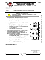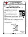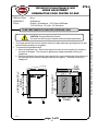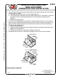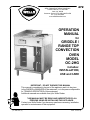
1
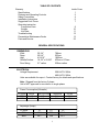
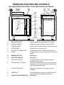
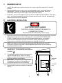
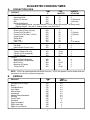
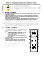
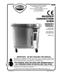
WELLS MANUFACTURING COMPANY
2 ERIK CIRCLE, P. O. Box 280
Verdi, NV 89439
Customer Service (775) 345-0444 Ext.502
fax: (775) 345-0569
www.wellsbloomfield.com
272
OPERATION
MANUAL
for
GRIDDLE /
RANGE TOP
CONVECTION
OVEN
MODEL
OC-2HG
includes:
INSTALLATION,
USE and CARE
IMPORTANT: DO NOT DISCARD THIS MANUAL
This manual is considered to be part of the appliance and is to be given
to the OWNER or MANAGER of the restaurant, or to the person responsible
for TRAINING OPERATORS of this equipment.
Additional manuals are available from your Wells Dealer.
THIS MANUAL MUST BE READ AND UNDERSTOOD BY ALL
PERSONS USING OR INSTALLING THIS APPLIANCE.
Contact your Wells Dealer if you have any questions concerning installation,
operation or maintenance of this equipment.
p/n 49657 Rev. (A)
M272 110100 cps
LIMITED WARRANTY STATEMENT
The prices charged by Wells Mfg. Co.for its products are based upon the limitations in this warranty.
Seller’s obligation under this warranty is limited to
the repair of defects without charge by a Wells Mfg.
Co. factory authorized service agency or one of its
sub-service agencies. This service will be provided
on customer’s premises for non-portable models.
Portable models (a device with a cord and plug) must
be taken or shipped to the closest authorized service agency, transportation charges prepaid, for service. In addition to restrictions contained in this warranty, specific limitations are shown in the Service
Policy and Procedure Guide. Wells Mfg. Co. authorized service agencies are located in principal cities. This warranty is valid in the United States and
Canada and void elsewhere. Please consult your
classified telephone directory, your foodservice
equipment dealer or write the Factory Service Department, Wells Manufacturing Company, P.O. Box
280, Verdi, Nevada 89439, phone (775) 345-0444
or (888) 492-2782, for information and other details
concerning warranty.
All commercial cooking equipment manufactured by
WELLS MFG. CO. is warranted against defects in
materials and workmanship for a period of one year
from the date of original installation or 18 months
from the date of shipment from our factory, whichever comes first, and is for the benefit of the original purchaser only.
THIS WARRANTY IS THE COMPLETE AND ONLY
WARRANTY, EXPRESSED OR IMPLIED IN LAW
OR IN FACT, INCLUDING BUT NOT LIMITED TO,
WARRANTIES OF MERCHANTABILITY OR FITNESS FOR ANY PARTICULAR PURPOSE, AND/OR
FOR DIRECT, INDIRECT OR CONSEQUENTIAL
DAMAGES IN CONNECTION WITH WELLS MFG.
CO. PRODUCTS. This warranty is void if it is determined that, upon inspection by an authorized service agency, the equipment has been modified, misused, misapplied, improperly installed, or damaged
in transit or by fire, flood or act of God. It also does
not apply if the serial nameplate has been removed,
or if service is performed by unauthorized personnel.
SERVICE POLICY AND PROCEDURE GUIDE
ADDITIONAL WARRANTY EXCLUSIONS
1. Resetting of safety thermostats, circuit breakers, overload protectors, and/or fuse replacements are not covered by this warranty unless
warranted conditions are the cause.
2. All problems due to operation at voltages or phase other than specified on equipment nameplates are not covered by this warranty.
Conversion to correct voltage and/or phase must be the customers responsibility.
3. All problems due to electrical connections not made in accordance with electrical code requirements and wiring diagrams
supplied with the equipment are not covered by this warranty.
4. Replacement of items subject to normal wear, to include such items as knobs, light bulbs; and, normal maintenance functions including
adjustments of thermostats, adjustment of micro switches and replacement of fuses and indicating lights are not covered by warranty.
5. Servicing of filters must be the customer’s responsibility. Replacement of filters and all problems associated with clogged filters are not
covered by this waranty. Inadequate airflow due to a clogged filter and/or grease baffle will disable fryers equipped witha ventilation
hood. Manufacturer assumes no responsibility for loss of business resulting from owner’s failure to have replacement filters available
when existing filters reach the end of their service life.
6. Set-up, adjustment, calibration, repair and servicing of third party equipment and systems, such as fire suppression systems, are not
covered by this warranty, and must be the customer’s responsibility.
7. Full use, care, and maintenance instructions are supplied with each machine. Noted maintenance and preventative maintenance items,
such as servicing and cleaning schedules, are customer responsibility. Those miscellaneous adjustments noted are customer
responsibility. Proper attention to preventatve maintenance and scheduled maintenance procedures will prolong the life of the machine.
8. Travel mileage is limited to sixty (60) miles from an Authorized Service Agency or one of its sub-service agencies.
9. All labor shall be performed during regular working hours. Overtime premium will be charged to the buyer.
10. All genuine Wells replacement parts are warranted for ninety (90) days from date of purchase on non-warranty equipment. This parts
warranty is limited only to replacement of the defective part(s). Any use of non-genuine Wells parts completely voids any warranty.
11. Installation, labor, and job check-outs are not considered warranty and are thus not covered by this warranty.
12. Charges incurred by delays, waiting time or operating restrictions that hinder the service technician’s ability to perform service are not
covered by warranty. This includes institutional and correctional facilities.
SHIPPING DAMAGE CLAIM PROCEDURE
NOTE: For your protection, please note that equipment in this shipment was carefully inspected and packaged by skilled personnel before leaving
the factory. Upon acceptance of this shipment, the transportation company assumes full responsibility for its safe delivery.
IF SHIPMENT ARRIVES DAMAGED:
1. VISIBLE LOSS OR DAMAGE: Be certain that any visible loss or damage is noted on the freight bill or express receipt, and that the note of
loss or damage is signed by the delivery person.
2. FILE CLAIM FOR DAMAGE IMMEDIATELY: Regardless of the extent of the damage.
3. CONCEALED LOSS OR DAMAGE: if damage is unnoticed until the merchandise is unpacked, notify the transportation company or carrier
immediately, and file “CONCEALED DAMAGE” claim with them. This should be done within fifteen(15) days from the date the delivery was
made to you. Be sure to retain the container for inspection.
Wells Manufacturing cannot assume liability for damage or loss incurred in transit. We will, however, at your request, supply you with the
necessary documents to support your claim.
xi
TABLE OF CONTENTS
Warranty
Specifications
Features and Operating Controls
Safety Procedures
Installation Instructions
Suggested Cook Times
Operating instruction
Convection Oven
Griddle
Hot Plate
Troubleshooting
Preventative Maintenance Cards
Parts and Service
Inside Cover
1
2
4
5
7
8
10
11
12
13
23
GENERAL SPECIFICATIONS
DIMENSIONS
Wide
Deep
High
Griddle Surface
Door Swing
30-1/4"
20-3-4"
41-9/16"
18-1/2" x 22-5/8"
21" radius
768mm
527mm
1050mm
470mm x 575mm
533mm radius
ELECTRICAL
Voltage Requirement
208 VAC 3∅ 60Hz
480 VAC 3∅ 60Hz
Units are available for export. Contact factory for details and specifications
Note: Shipped from the factory 3 phase.
Unit is NOT approved for conversion to single phase
Power Consumption (Kilowatts)
3∅ 60Hz
208V
480V
OVEN
4.2
5.6
HOTPLATES
3.0
5.2
GRIDDLE
6.8
6.0
Amperage (Amps)
3∅ 60Hz
208V
480V
L1
42.2
20.7
L2
37.2
19.6
1
L3
39.2
20.1
TOTAL
14.0
16.8
OPERATING FEATURES AND CONTROLS
LEFT-HAND GRIDDLE UNIT SHOWN - RIGHT-HAND GRIDDLE UNIT SIMILAR
A.
GREASE DRAWER
Catches grease and cooking waste from griddle.
B.
VIEWING WINDOW
Allows monitoring of product in convection oven.
C.
CONTROL PANEL
Allows control of time and temp of cooking equipment.
D.
DOOR HANDLE
Latches door of convection oven.
E.
ELECTRICAL CONNECTION
Provided by electrician. (Shown for location only).
F.
FUSES
Provide electrical over-current protection for oven and
griddle.
G.
GRIDDLE SECTION
See page 10
H.
HOTPLATE SECTION
See page 11
J.
COOLING LOUVERS
Provides cooling air for heat dissipation around
components and controls.
K.
SPLASH SHIELD / SPACER
Positions unit proper distance from wall for required
ventilation. Also prevents liquids from entering right
side equipment compartment.
L.
6" ADJUSTABLE LEGS
Allows unit to be leveled. Also raises unit for air
circulation.
M.
NAMEPLATE
Gives manufacturer information, model # & serial #.
Also gives electrical data and requirements
V.
CONVECTION OVEN SECTION
See page 8
2
CONTROL PANEL FEATURES
GRIDDLE SECTION
G.01
GRIDDLE TEMPERATURE CONTROL:
Thermostat, controls 0ºF(OFF) to 400ºF
G.02
GRIDDLE HEAT ON INDICATOR
HOTPLATE SECTION
H.01
FRONT HOTPLATE TEMPERATURE
CONTROL: Infinite Switch, OFF to HIGH
H.02
FRONT HOTPLATE HEAT ON INDICATOR
H.03
REAR HOTPLATE TEMPERATURE
CONTROL: Infinite Switch, OFF to HIGH
H.04
REAR HOTPLATE HEAT ON INDICATOR
CONVECTION OVEN SECTION
V.01
OVEN POWER SWITCH, 3 position
ON (oven + fan) - OFF - FAN (only)
V.02
FAN SPEED SWITCH, 2 position
HI - LOW
V.03
OVEN POWER ON INDICATOR
V.04
OVEN HEAT ON INDICATOR
V.05
DIGITAL READOUT: Displays oven
temperature, cook time and oven
programming information
A.
TEMPERATURE DISPLAY(ºF)
B.
TIME DISPLAY (minutes:seconds)
C.
ERROR CODES (see page 12)
V.06
OVEN TIME CONTROL
V.07
OVEN TEMPERATURE CONTROL
V.08
TIMER / PROGRAM START BUTTON
V.09
ACTUAL TEMP BUTTON: Press to view
current oven Farenheit temperature on
readout
V.10
PROGRAM SELECTION BUTTONS:
Press and hold while turning controls to
program time and temp
Press and release to begin program
V.11
CANCEL BUTTON: Press to: cancel a
selected program in progress; or,
to silence the audible alarm at the end of
a cook cycle
3
SAFETY PROCEDURES
Knowledge of proper procedures is essential to the safe operation of electrically energized
equipment. In accordance with generally accepted product safety labeling guidelines for
potential hazards, the following signal words and symbols are used throughout this manual.
DANGER
DANGER - Danger is used to indicate the presence of a hazard which will
cause severe personal injury, death or substantial property damage in the
event the statement is ignored.
WARNING - Warning is used to indicate the presence of a hazard which can cause
personal injury and possibly death or major property damage in the event the
statement is ignored.
CAUTION - Caution is used to indicate the presence of a hazard which will or can
cause minor personal injury or property damage in the event the statement is ignored.
CAUTION - Used to indicate the presence of an electrical hazard which will or can
cause personal injury or property damage in the event the statement is ignored.
NOTE - Note is used to notify personnel of installation, operation or maintenance
information which is important, but not hazard related.
PRECAUTIONS AND GENERAL INFORMATION
1.
This appliance is intended for use to cook food products for human consumption. No other use
is recommended or authorized by the manufacturer or its agents.
2.
This appliance is intended for use in commercial establishments only, where all operators are
familiarwith the appliance use, limitations and associated hazards. Operating instructions and
warnings must be read and understood by all operators and users.
3.
Unless otherwise noted, this piece of equipment is made in the USA and has American sizes on
hardware.
4.
Any trouble shooting guides, component views or parts lists included in this manual are for general
reference only, and are intended for use by qualified technical personnel.
5.
This manual should be considered a permanant part of this appliance. This manual and all
supplied instructions, diagrams, schematics, parts break downs, notices and labels must remain
with the appliance if it is sold or moved to another location.
4
INSTALLATION INSTRUCTIONS
A.
UNPACKING AND INSPECTION
1. Carefully remove equipment from the carton. Remove all protective plastic film and
packaging materials. Remove accessories from the OVEN CAVITY and GRIDDLE
GREASE DRAWER before connecting electrical power or otherwise performing any
installation procedures.
NOTE: DO NOT discard the CARTON and other PACKAGING MATERIAL until you have
inspected the appliance for hidden damage and tested it for PROPER OPERATION.
Refer to SHIPPING DAMAGE CLAIM PROCEDURE on the inside front cover of this manual.
2. Read all instructions in this manual carefully before starting installation . READ AND
UNDERSTAND ALL LABELS AND DIAGRAMS ATTACHED TO THE APPLIANCE.
3. Carefully account for all components and accessories before discarding packing materials.
Components and accessories are shipped in the oven cavity and in the grease drawer.
Store the accessories in a convenient place for later use:
B.
COMPONENTS
4 ea.
5 ea.
6" ADJUSTABLE LEGS
OVEN RACKS
ACCESSORIES
1 ea.
LITERATURE PACKAGE
SERVICE TECHNICIAN INSTALLATION NOTES
1. Installation and start up should be performed by an authorized installation company.
Installer must record installation particulars on the CUSTOMER SERVICE DATA form
on page 23 of this manual.
2. Verify that this equipment installation is in compliance with the specifications listed in this
manual and with local code requirements.
It is the RESPONSIBILITY OF THE INSTALLER to check with the AUTHORITY HAVING
JURISDICTION, in order to verify compliance with local codes and ordinances for THIS
SPECIFIC EQUIPMENT INSTALLATION.
3. This cooking appliance requires a minimum of 3" clearance from back and sides. Unless the
unit is curb-mounted, 6" clearance from the floor is required for cleaning. The legs provided
with this equipment will provide proper floor clearance.
NOTE: Optional casters are available (in a set of 4) as p/n 21330.
5
C.
EQUIPMENT SET-UP
1.
Install 6" adjustable legs or optional casters, one on each corner of the appliance, in the holes
provided.
2.
Setup the appliance only on a firm, level, non-combustable surface. Verify local codes for
requirements. Concrete, tile, terrazzo or metal surfaces are recommended. Metal over
combustible material may not meet code for non-combustible surfaces.
3.
LEVELING: Verify that the appliance sits firmly ON ALL FOUR LEGS OR CASTERS. With a spirit
level, check that the appliance is level front-to-back and side-to-side. With the adjustable legs,
adjust as required to level the appliance.
D.
ELECTRICAL INSTALLATION
DANGER
ELECTRICAL SHOCK HAZARD
ELECTRICAL CONNECTIONS MUST BE MADE BY A
LICENSED ELECTRICIAN
Electrical shock will cause death or serious injury.
1.
Electrical connection terminal block and ground lug are accessible by removing the right side panel.
2.
Refer to the nameplate on the front of the appliance. Verify the ELECTRICAL SERVICE
POWER. Voltage and phase must match the nameplate specifications, and available
electrical service amperage must meet or exceed the specifications listed on page 1.
Wiring must be no less than 4 AWG solid copper wire, rated for at least 90ºC.
NOTE: Wire gauge, insulation type and temperature rating , as well as type, size and
construction of conduit, must meet or exceed applicable specifications of local codes and
of the National Electrical Code.
3.
This appliance must be connected to a suitable
building ground. The equipment ground connection
is marked "
4.
".
The appliance is shipped from the factory wired for
3-phase electrical service. Refer to the Wiring
Diagram included with this appliance, and verify that
field wiring conforms to this diagram.
IMPORTANT: This appliance is not approved for
1Ø operation. Conversion of this appliance to
single-phase operation will void the warranty.
5.
Reinstall right side panel at completion of electrical
hook-up.
6
TERMINAL
BLOCK
L1 L2 L3
GROUND
LUG
SUGGESTED COOKING TIMES
A.
CONVECTION OVEN
PRODUCT
TEMP
ºF
TIME
MINUTES
NUMBER
OF RACKS
BREAD PRODUCTS
Hamburger Roll
300
15
5
Bread (1 lb loaves)
325
34
3 (12 loaves)
Roll
300
16
5 (60 rolls)
Baking Soda Biscuit
400
7
3
For best baking results, use rack positions 2, 5 & 8 ( where rack position 1 is the top rack)
Baking one pan: use rack 5; baking 2 pans: use racks 2 & 8.
PASTRIES
Sheet Cake (2½ lbs. per pan)
300
17
5
Frozen Fruit Pie (46oz.)
350
50
5 (10 pies)
Frozen Fruit Pie (26oz. - 8" dia.)
350
40
5 (15 pies)
Sugar Cookie
300
15
5
Danish Roll
350
12
5
Fruit Cake
275
75
3
Cake (1 lb.)
300
19
5 (10 cakes)
FISH
Fish Stick
350
15
5
Halibut Steak (Frozen 5 oz.)
350
20
5
FOWL
Turkey, Rolled (18 lb. roll)
310
3¾ hr
1
Chicken (2½ lb. quartered)
350
30-35
5
Chicken (Breast)
350
30
5
OTHER
Melted Cheese Sandwich
400
8
5
Idaho Potato (120 potatoes)
450
40
5
Beef Pot Pie
400
30-35
5
Macaroni & Cheese
350
30
5
Turkey Pot Pie
400
30-35
5
NOTE: "HIGH" fan speed provides the fastest cook time. "LOW" fan speed is used for foods which are
sensitive to air currents, such as meringue pie.
B.
GRIDDLE
PRODUCT
TEMP
ºF
TIME
MINUTES
Sausage (Link or Patty)
Bacon
Canadian Bacon
Ham Steak
Minute Steak
Hamburger
Melted Cheese Sandwich
Hot Dog
French Toast
Pancakes
Eggs, Scrambled
Eggs, Hard Fried
Eggs, Sunny Side Up
350
350
350
375
400
350
375
325
350
375
300
300
300
3-4
2-3
2-3
3-4
3-4
3-4
3-4
2-3
2-3
2
1-2
3
2
7
CONVECTION OVEN OPERATING INSTRUCTIONS
CAUTION: Electric Shock Hazard
DO NOT splash or pour water onto control panel or wiring.
CAUTION: Burn Hazard
Oven surfaces can be hot to the touch and can cause burns on contact.
A.
MANUAL COOK MODE
1.
Set the OVEN POWER SWITCH (V.01) to ON. The OVEN POWER ON INDICATOR (V.03) will be
lit when the switch is ON.
2. Rotate OVEN TEMPERATURE CONTROL knob (V.07) until the desired cooking temperature is
displayed on the READOUT (V.05A). The oven will begin heating, and the temperature digits will
flash, until the set temperature is reached.
3. Rotate OVEN TIME CONTROL knob (V.06) until the desired time is displayed on the READOUT.
The digits and colon will flash, indicating that time has been set but the timer is not started.
4. Load product in the oven. Press START TIMER key (V.08). The timer digits count down and the
colon (only) flashes during the timer period.
5. At the end of the timer period, an audible alarm will sound. Press CANCEL key (V.11) to silence the
alarm.
HINT: For best baking results when making baking soda biscuits, use rack positions 2, 5 & 8 ( where
rack position 1 is the top rack). When baking one pan: use rack 5 (center rack); when baking 2
pans: use racks 2 & 8; when baking three pans: use racks 2, 5 & 8.
B.
PROGRAM COOK MODE
1.
2.
3.
4.
5.
Five (5) programmable keys (V.10) are provided for presetting
frequently used time / temperature combinations. To set the
program:
a.
Press and hold the appropriate PGM key.
b.
While holding the PGM key, turn the TIME and TEMP
knobs until the desired time and temperature is
displayed on the readout.
c.
Release the PGM key to store the displayed time and
temp in memory.
The program for any PGM key can be recalled by momentarily
pressing that PGM key.
To start a programmed cook cycle, press the appropriate
PGM key and the START TIME key. Once the cook cycle
has started, the TIME and TEMP knobs are locked out to
prevent accidental re-programming.
The actual oven temperature may be recalled at any time
by pressing the ACTUAL TEMP key (V.09).
At the end of the timer period, an audible alarm will sound.
Press CANCEL key (V.11) to silence the alarm.
8
C.
TEMPERATURE OFFSET MODE
1.
2.
D.
A user preference offset mode is provided should the user feel the oven cooks too hot or too cold.
The OFFSET MODE can be used to offset the set / displayed temperature from the sensed
temperature by as much as ± 35ºF, in 5ºF increments:
a.
Rotate the TIME controller until the time digits on the display read "00:00".
b.
Rotate the TEMP control until the temp digits display between 400º and 500º.
c.
Press and hold the START TIMER key for five seconds.
d.
Turn either the TIME or TEMP control until the desired offset is displayed.
e.
Press the ACTUAL TEMP key to exit.
CONVECTION OVEN CLEANING INSTRUCTIONS
CAUTION: Burn Hazard
Do not attempt to clean the oven until it has cooled to 150ºF or less
1. Turn OVEN POWER SWITCH to FAN and FAN SPEED SWITCH to HIGH. With the door held
open, allow the oven to cool. When the oven interior has cooled to 150ºF or less, turn the OVEN
POWER SWITCH to OFF.
2. Remove racks and rack suports. Remove fan baffle.
CAUTION: Cut Hazard
FAN BLADES ARE SHARP. Use care when cleaning and/or wiping.
3.
4.
5.
6.
Brush the fan wheel and wipe it with a moist cloth. Sponge out all loose particles.
Scrub entire interior of convection oven with a plastic scouring pad and non-abrasive
cleanser.
For baked-on food spills, sparingly use a conventional oven cleaner. Wipe the area with vinegar
solution to neutralize the oven cleaner.
Wipe down the entire interior using a clean cloth or sponge, with hot water and a mild detergent.
IMPORTANT: Always wipe or rub in the direction of the polish lines or grain of the metal.
7.
Clean oven door glass. NEVER USE ABRASIVE SCRUB PADS on the door glass. Always read
and follow direction on the container when using commercial cleaners. Dry with soft clean cloth.
8. Clean oven racks and rack supports in a sink or dishwasher.
9. Reinstall the fan baffle, paying particular attention that the lip on the right side of the fan baffle is fully
seated in the slot in the edge of the oven cavity. Reinstall rack supports and racks.
10. Turn power switch to FAN and fan switch to LOW. Verify that fan runs smoothly and does not
contact fan baffle. Turn power switch to OFF. Reposition fan baffle if necessary.
9
GRIDDLE OPERATING INSTRUCTIONS
CAUTION: Electric Shock Hazard
DO NOT splash or pour water onto control panel or wiring.
A.
SEASONING
WARNING: Hot Surfaces
Griddle surface can be VERY HOT and may cause severe burns on contact.
The metal surface of the griddle has microscopic pores. It is important to fill the pores with oil to provide a
hard, non-stick cooking surface.
1.
2.
3.
4.
5.
B.
Turn GRIDDLE TEMPERATURE CONTROL (G.01) clockwise to 375ºF. Allow the griddle to heat
until the GRIDDLE HEAT ON INDICATOR (G.02) goes OFF, showing that the griddle is up to the set
temperature.
Spread a light film of oil over the entire griddle surface.
Allow the oil film to "cook in" for 2 - 3 minutes, or until the oil smokes.
Wipe the griddle surface with a clean cloth to remove any standing oil.
For new griddles, repeat this procedure 2 - 3 times, until the griddle has a slick, clean surface.
COOKING WITH YOUR GRIDDLE
WARNING: Hot Surfaces
Griddle surface can be VERY HOT and may cause severe burns on contact.
1.
2.
C.
Turn the GRIDDLE TEMPERATURE CONTROL (G.01) to the desired cooking temperature. The
solid-state thermostatic controller will automatically maintain set temperature.
The GRIDDLE HEAT ON INDICATOR(G.02) will be ON when the heating elements are energized.
GRIDDLE CLEANING INSTRUCTIONS
1.
2.
To keep the griddle clean and food flavors at their best, scrape the griddle after preparing each
order. Scrape excess food into the waste hole in the grease trough (front of the griddle cooking
surface). After each 2 - 3 orders, wipe the griddle surface with a light coat of oil.
Clean the griddle surface daily, at a minimum:
a.
Set temperature control to 220ºF. Allow the griddle temperature to drop to 220ºF before
proceeding.
b.
Pour a small amount of water on the griddle surface and let it "sizzle".
c.
Use a pumice stone or griddle brick to remove all remaining waste, and to clean the griddle
surface down to bright metal. Wipe off any remaining powder residue.
IMPORTANT: NEVER USE STEEL WOOL TO CLEAN THE GRIDDLE SURFACE!
d.
e.
3.
Use a soft-bristled fiber brush in a circular motion to remove any remaining food particles.
Turn temperature control to OFF. Allow the griddle surface to cool, then wipe the surface
with a clean cloth.
f.
Dry the griddle surface thoroughly.
g.
Season the cooking surface after each cleaning using the instructions above.
At least once each day, the GREASE TROUGH must be thoroughly cleaned. Using a scraper,
remove all grease and food waste from the grease trough and into the grease drawer.
10
4.
5.
After scraping all cooking waste from grease trough into GREASE DRAWER, take the grease
drawer to kitchen cleaning area and properly dispose of all waste.
a.
Clean drawer with hot water and a mild detergent.
b.
Dry drawer thoroughly and reinstall in griddle.
GRIDDLE EXTERIOR:
a.
Wipe down splash guards, griddle body and the grease trough with a cloth dampened with
warm water and a mild detergent.
b.
A plastic scouring pad and a non-abrasive cleanser may be used for hard-to-remove food
particles.
c.
Rinse thoroughly with clean water. DO NOT splash or pour water onto control panel or
wiring.
d.
Dry griddle with a soft, clean cloth.
HOTPLATE OPERATING INSTRUCTIONS
CAUTION: Electric Shock Hazard
DO NOT splash or pour water onto control panel or wiring.
A.
COOKING WITH YOUR HOTPLATE
WARNING: Hot Surfaces
Hotplate surfaces can be VERY HOT and may cause severe burns on contact.
1.
2.
3.
4.
5.
6.
B.
Each element is individually controlled by a TEMPERATURE CONTROL (H.01 and H.03). These
are infinite switch controls which control based on electrical current draw, not the actual temperature
of the hotplate surface.
Settings are OFF to HIGH.
The associated indicator will be lit when the switch is in any position other than OFF.
When set to HIGH, the hotplate element can reach maximum temperature in seconds.
This eliminates pre-heating.
Once liquid begins to boil, reduce the setting to minimize power consumption and increase the
useful life of the elements.
Use cooking pans which fully cover the elements for maximum efficiency.
HOTPLATE CLEANING INSTRUCTIONS
CAUTION: Burn Hazard
Do not attempt to clean the elements until they are cool.
1.
2.
Turn both controls to OFF. Allow both hotplate elements to cool.
Wipe the entire hotplate top panel using a clean cloth or sponge, with hot water and a mild
detergent. For burned-on foods or sauce spillage, use a non-abrasive cleanser applied with a
plastic scouring pad.
IMPORTANT: Always wipe or rub in the direction of the polish lines or grain of the metal.
11
TROUBLESHOOTING SUGGESTIONS
CAUTION: ELECTRICAL SHOCK HAZARD
Removal of any cabinet panel will result in exposed electrical circuits.
Any procedure requiring the removal of any cabinet panel must be performed
by a qualified technician only.
A.
NO PART OF THE APPLIANCE WILL HEAT
1.
2.
3.
B.
Verify that appropriate cooking controls are ON.
Check electrical supply. Make sure service breaker is ON.
Possible improper service wiring: Have a licensed electrician verify that all three legs of the 3∅
service are properly connected (i.e. Leg 1 to L1, Leg 2 to L2, Leg 3 to L3), and that all three legs are
of the proper voltage and phase.
OVEN AND GRIDDLE WILL NOT HEAT (HOTPLATE ONLY WILL HEAT)
1.
2.
C.
Blown fuses (item F): Correct cause of over-current and replace fuses with fuses having the same
configuration and ratings.
Possible internal component damage: Have unit serviced by an Authorized Wells Service Agency.
GRIDDLE WILL NOT HEAT
1.
2.
D.
Verify that temperature control is set to the desired temperature.
Possible internal component damage: Have unit serviced by an Authorized Wells Service Agency.
HOTPLATE WILL NOT HEAT
1.
2.
E.
Verify that associated temperature control is set to the desired temperature.
Possible internal component damage: Have unit serviced by an Authorized Wells Service Agency.
CONVECTION OVEN WILL NOT HEAT
1.
2.
3.
4.
5.
F.
Verify that the oven switch is ON and that the temperature control is set to the desired temperature.
Verify that the door is closed.
Hi-Limit control may have tripped: Allow unit to cool; Hi-Limit will reset automatically.
Blown fuse(s) (item F): Correct cause of over-current and replace fuses with fuses having the same
configuration and ratings.
Possible internal component damage: Have unit serviced by an Authorized Wells Service Agency.
CONVECTION OVEN FAN WILL NOT RUN
1.
2.
3.
4.
5.
G.
Verify that the oven switch is set to ON or FAN.
Verify that the fan switch is set to either HIGH or LOW.
Hi-Limit control may have tripped: Allow unit to cool; Hi-Limit will reset automatically.
Blown fuse(s) (item F): Correct cause of over-current and replace fuses with fuses having the same
configuration and ratings.
Possible internal component damage: Have unit serviced by an Authorized Wells Service Agency.
CONVECTION OVEN CONTROLLER DISPLAYS ERROR CODE
F1
F2
F3
F4
F5
F6
Relay closed or relay ohms low when not cooking
Actual temperature greater than T-SET MAX +60ºF (±35ºF)
Open temperature sensor
Shorted temperature sensor
Relay open or relay ohms high when cooking
No 60 Hz (Cycles per second other than 60 Hz detected)
12
Have unit serviced by an
Authorized Wells Service
Agency.
PREVENTATIVE MAINTENANCE CARD
PM 272.1
PREPARATIONS:
Discussed in each section below
FREQUENCY:
Daily
TOOLS:
Griddle Brick or Pumice Stone
Fiber Brush
Plastic Scouring Pad, Plastic Scraper
Mild Detergent, Conventional Oven Cleaner, Non-Abrasive Cleanser
Clean Soft Cloth / Sponge
Solution: 4 parts vinegar to 10 parts warm water
A.
GRIDDLE CLEANING INSTRUCTIONS
1.
2.
3.
Set temperature control to 220ºF. Allow the griddle temperature to drop to 220ºF before
proceeding.
Pour a small amount of water on the griddle surface and let it "sizzle".
Use a pumice stone or griddle brick to remove all remaining waste, and to clean the
griddle surface down to bright metal. Wipe off any remaining powder residue.
IMPORTANT: NEVER USE STEEL WOOL TO CLEAN THE GRIDDLE SURFACE!
4.
5.
Use a soft-bristled fiber brush in a circular motion to remove any remaining food particles.
Turn temperature control to OFF. Allow the griddle surface to cool, then wipe the surface
with a clean cloth. Dry the griddle surface thoroughly.
IMPORTANT: Season the cooking surface after each cleaning.
6.
7.
At least once each day, the GREASE TROUGH must be thoroughly cleaned. Using a
scraper, remove all grease and food waste from the grease trough and into the grease
drawer.
After scraping all cooking waste from grease trough into the grease drawer, take the
grease drawer to kitchen cleaning area and properly dispose of all waste.
a.
Clean drawer with hot water and a mild detergent.
b.
Dry drawer thoroughly and reinstall in griddle.
IMPORTANT: DO NOT splash or pour water onto control panel or wiring.
PROCEED TO SECTION B.
page 1 of 3
13
DO NOT REMOVE FROM MANUAL - PHOTOCOPY FOR DISTRIBUTION
CLEANING INSTRUCTIONS
COMBINATION COOK CENTER OC-2HG
PREVENTATIVE MAINTENANCE CARD
272.1
CLEANING INSTRUCTIONS
COMBINATION COOK CENTER OC-2HG
B.
CONVECTION OVEN CLEANING INSTRUCTIONS
CAUTION: BURN HAZARD
Do not attempt to clean the oven until it has cooled to 150ºF or less
1.
DO NOT REMOVE FROM MANUAL - PHOTOCOPY FOR DISTRIBUTION
2.
Turn OVEN POWER SWITCH to FAN and FAN SPEED SWITCH to HIGH. With the
door held open, allow the oven to cool. When the oven interior has cooled to 150ºF
or less, turn the OVEN POWER SWITCH to OFF.
Remove racks and rack suports. Remove fan baffle.
CAUTION: CUT HAZARD
FAN BLADES ARE SHARP. Use care when cleaning and/or wiping.
3.
4.
5.
6.
Brush the fan wheel and wipe it with a moist cloth. Sponge out all loose particles.
Scrub entire interior of convection oven with a plastic scouring pad and non-abrasive
cleanser.
For baked-on food spills, sparingly use a conventional oven cleaner. Wipe the area
with vinegar solution to neutralize the oven cleaner.
Wipe down the entire interior using a clean cloth or sponge, with hot water and a mild
detergent.
IMPORTANT: Always wipe or rub in the direction of the polish lines or grain of
the metal.
7.
Clean oven door glass. NEVER USE ABRASIVE SCRUB PADS on the door glass.
Always read and follow direction on the container when using commercial cleaners.
Dry with soft clean cloth.
8. Clean oven racks and rack
supports in a sink or dishwasher.
9. Reinstall the fan baffle, paying
particular attention that
the lip on the right side of the fan
baffle is fully seated in the slot in
the edge of the oven cavity.
Reinstall rack supports and racks.
10. Turn power switch to FAN and fan
switch to LOW. Verify thatfan runs
smoothly and does not contact
fan baffle.
Turn power switch to OFF.
Reposition fan baffle if necessary.
PROCEED TO SECTION C.
page 2 of 3
14
PREVENTATIVE MAINTENANCE CARD
272.1
CLEANING INSTRUCTIONS
COMBINATION COOK CENTER OC-2HG
C.
HOTPLATE CLEANING INSTRUCTIONS
CAUTION: BURN HAZARD
Do not attempt to clean the elements until they are cool.
1.
2.
Turn both controls to OFF. Allow both hotplate elements to cool.
Wipe the entire hotplate top panel using a clean cloth or sponge, with hot water and a
mild detergent. For burned-on foods or sauce spillage, use a non-abrasive cleanser
applied with a plastic scouring pad. Rinse thoroughly with clean water.
IMPORTANT: Always wipe or rub in the direction of the polish lines or grain of
the metal.
D.
CABINET
1.
Wipe down the sides of the appliance using a clean cloth or sponge, with hot water and
a mild detergent. For burned-on food or sauce spillage, use non-abrasive cleanser
appliedwith a plastic scouring pad. Rinse thoroughly with clean water.
2.
Wipe down exterior of griddle, splash guards, grease trough and hotplate area with a
cloth dampened with warm water and a mild detergent. A plastic scouring pad and a
non-abrasive cleanser may be used for hard-to-remove food particles. Rinse thoroughly
with clean water.
IMPORTANT: DO NOT splash or pour water onto control panel or wiring.
3.
Rinse appliance with a clean damp cloth or sponge, and dry with a soft, clean cloth.
PROCEDURE IS COMPLETE
04/04/00
page 3 of 3
15
WELLS MANUFACTURING COMPANY
2 ERIK CIRCLE, P. O. Box 280
Verdi, NV 89439
Customer Service (775) 345-0444 Ext.502
fax: (775) 345-8238
www.wellsbloomfield.com
DO NOT REMOVE FROM MANUAL - PHOTOCOPY FOR DISTRIBUTION
CAUTION: ELECTRICAL SHOCK HAZARD
DO NOT splash or pour water onto control panel or wiring.
PM272.1
16
PREVENTATIVE MAINTENANCE CARD
272.2
TEMPERATURE CALIBRATION
COMBINATION COOK CENTER OC-2HG
PRECAUTIONS:
None
FREQUENCY:
Monthly
TOOLS:
Digital Thermometer with Oven Probe, Protective Gloves
1. With the oven empty, clamp the thermocouple sensor in the
middle of the middle rack:
a.
Pass the thermocouple sensor wires through the
corner of the door gasket and close the door.
b.
Plug the sensor into the Pyrometer.
2. Turn the OVEN POWER (V.01) switch to ON. Turn the FAN
switch (V.02) to HI.
a.
Rotate the TIME control (V.06) until the time digits
(V.05B)on the display read "60:00".
b.
Rotate the TEMP control (V.07) until the temp digits
(V.05A) display 375º.
c.
Press the START TIMER key (V.08).
3. Allow the oven to heat for 45 minutes. If, after 45 minutes,
the temp display reads between 370º and 380º and
matches the temperature on the digital thermometer, the
calibration is satisfactory. Otherwise:
a.
Rotate the TIME controller until the time digits (V.05B)
on the display read "00:00".
b.
Rotate the TEMP control until the temp digits (V.05A)
display between 400º and 500º.
c.
Press and hold the START TIMER (V.08) key for five
seconds.
d.
Turn either the TIME or TEMP control until the desired
offset is displayed.
e.
Press the ACTUAL TEMP (V.09) key to exit.
PROCEDURE IS COMPLETE
04/04/00
page 1 of 1
17
WELLS MANUFACTURING COMPANY
2 ERIK CIRCLE, P. O. Box 280
Verdi, NV 89439
Customer Service (775) 345-0444 Ext.502
fax: (775) 345-8238
www.wellsbloomfield.com
DO NOT REMOVE FROM MANUAL - PHOTOCOPY FOR DISTRIBUTION
CAUTION: HOT SURFACES
Oven surfaces will be hot. Hot surfaces will cause burns on contact.
Wear protective gloves
PM272.2
18
PREVENTATIVE MAINTENANCE CARD
272.3
LATCH ADJUSTMENT
COMBINATION COOK CENTER OC-2HG
PRECAUTIONS:
None
FREQUENCY:
As Required
TOOLS:
Phillips (+) Screwdriver, 4"x2" Strip of 20# Paper
PROCEEDURE IS COMPLETE
BACK PLATE
STRIKER
FRONT PLATE
04/04/00
page 1 of 1
19
WELLS MANUFACTURING COMPANY
2 ERIK CIRCLE, P. O. Box 280
Verdi, NV 89439
Customer Service (775) 345-0444 Ext.502
fax: (775) 345-8238
www.wellsbloomfield.com
DO NOT REMOVE FROM MANUAL - PHOTOCOPY FOR DISTRIBUTION
1. The door latch must be adjusted such that the door
will latch easily, yet remain closed and latched throughout
the cook cycle.
If the door is too tight when the oven is cold, it may pop
open as the oven reaches temperature.
2. Check adjustment in two places on the latch-side of the
door.
Use a piece of paper (such as a dollar bill) between the
inner surface of the door and the door gasket, just above
and just below the latch. The paper should be definitely
held, but should be able to be pulled out with just a slight
drag.
3. To adjust the vertical alignment, hold the striker assembly
while loosening the two screws. Move the striker assembly
LATCH
as needed, but do not allow the parts of the striker to move
in relation to each other. Retighten the screws and re-check
the alignment.
4. To adjust the fore-and-aft alignment, the back plate acts as a tapered shim. Moving
the back plate vertically, in relation to the striker, will adjust the thickness of the striker
assembly. When properly adjusted for thickness, verify the vertical alignment and
tighten the screws.
5. Recheck the alignment. Recheck the tightness of the screw.
CHECK ALIGNMENT
TO BE PERFORMED BY QUALIFIED PERSONEL ONLY
PM272.3
20
PREVENTATIVE MAINTENANCE CARD
272.4
HINGE ADJUSTMENT
COMBINATION COOK CENTER OC-2HG
PRECAUTIONS:
None
FREQUENCY:
As Required
TOOLS:
Phillips (+) Screwdriver, 4"x2" Strip of 20# Paper
7/16" Nut Driver, 7/8" and 1-1/8" Wrenches
CAUTION: Exposed Electrical Circuits
Use care to avoid wiring for hotplate section during this procedure
1. The hinges provide the pivot for the door, allow for height adjustment and alignment so that
the door closes properly on the gasket.
2. To access the hinge adjustments:
a. Remove the grease tray. Remove the upper trim panel by removing the four screws at
the ends of the panel. The trim panel / grease tray support assembly will then pull
straight out.
b. Remove the bottom trim panel by removing the four screws at the ends of the panel, and
by loosening the two screws holding the bottom door gasket. The panel will then pull
straight out.
CHECK ALIGNMENT
APPROXIMATELY
EQUAL
CLEARANCES
TOP
PANEL
BOTTOM
PANEL
04/04/00
page 1 of 2
21
DO NOT REMOVE FROM MANUAL - PHOTOCOPY FOR DISTRIBUTION
TO BE PERFORMED BY QUALIFIED PERSONEL ONLY
PREVENTATIVE MAINTENANCE CARD
272.4
HINGE ADJUSTMENT
COMBINATION COOK CENTER OC-2HG
DO NOT REMOVE FROM MANUAL - PHOTOCOPY FOR DISTRIBUTION
3. The door should be approximately centered between the upper and lower lips of the cabinet.
Adjust the door for height:
a. The hinge sleeve acts as a jam nut for the height adjuster.
b. The top and bottom clearances should be approximately equal. If necessary, loosen the
hinge sleeve and turn the height adjustment nut until the required clearances are
achieved.
c. Retighten the hinge sleeve.
4. Check fore-and-aft adjustment in two places on the hinge-side of the door. Use a piece of
paper (such as a dollar bill) between the inner surface of the door and the door gasket. The
paper should be definitely held, but should be able to be pulled out with just a slight drag.
5. To adjust a top or bottom hinge:
a. Loosen the holding bolts.
b. Tighten or loosen the adjusting bolt as needed to achieve the proper vertical clearance(s).
c. Retighten the holding bolts.
d. Recheck the clearances. Recheck the tightness of the bolts.
6. Reassemble the trim panels. Remember to retighten the screws for the lower gasket.
HINGE BRACKET
HOLDING
BOLTS
DOOR PIVOT
ADJUSTING
BOLT
HINGE SLEEVE
HINGE BRACKET
HOLDING
BOLTS
HEIGHT
ADJUSTMENT
ADJUSTING
BOLT
PROCEDURE IS COMPLETE
04/04/00
page 2 of 2
22
WELLS MANUFACTURING COMPANY
2 ERIK CIRCLE, P. O. Box 280
Verdi, NV 89439
Customer Service (775) 345-0444 Ext.502
fax: (775) 345-8238
www.wellsbloomfield.com
PARTS and SERVICE
IMPORTANT: Use only factory authorized service parts.
For factory authorized service, or to order factory authorized replacement parts, contact your
WELLS AUTHORIZED SERVICE AGENCY, or call:
Wells Manufacturing Company
2 Erik Circle, P. O. Box 280
Verdi, NV 89439
phone: (775) 345-0444 ask for Service Department
fax: (888) 492-2783
Service Parts Department can supply you with the name / telephone number of the WELLS
AUTHORIZED SERVICE AGENCY nearest you.
ACCESSORIES
PART#
CASTER SET, OVEN (set of 4)
OVEN RACK, REPLACEMENT
LEG KIT, OVEN, S/S (set of 4)
21330
21376
22226
CUSTOMER SERVICE DATA
please have this information available if calling for service
RESTAURANT _____________________________ LOCATION _______________
INSTALLATION DATE ________________________ TECHNICIAN _____________
SERVICE COMPANY __________________________________________________
ADDRESS ___________________________ STATE ______ ZIP__________
TELEPHONE NUMBER (_____)_____-_________
EQUIPMENT MODEL NO. ______________________________________________
EQUIPMENT SERIAL NO. ______________________________________________
VOLTAGE: (check one)
208V
480V
23
WELLS MANUFACTURING COMPANY
2 ERIK CIRCLE, P. O. Box 280
Verdi, NV 89439
Customer Service (775) 345-0444 Ext. 502
fax: (775) 345-0569
www.wellsbloomfield.com