1
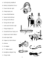
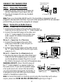
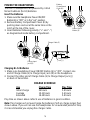
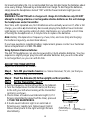
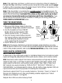
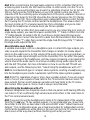
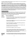
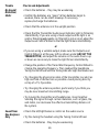
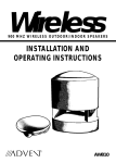
Wireless
WIRELESS STEREO HEADPHONES
INSTALLATION AND
OPERATING INSTRUCTIONS
AW770
Wireless Stereo Headphones
Installation and Operation Manual
Model AW770
CONTENTS
Connect the Transmitter .............................................................................................. 4
Power the Headphones .............................................................................................. 5
Adjust the Transmitter.................................................................................................. 6
Tune the Headphones .................................................................................................. 7
More Helpful Information ............................................................................................ 7
Troubleshooting ............................................................................................................ 9
Specifications & Features ........................................................................................ 11
INTRODUCTION
Advent Wireless Headphones expand and enhance your enjoyment of the audio
sources (TV, stereo, etc.) in your home. Like FM radio, the Advent Wireless
Headphone System’s 900 MHz signals travel with ease through walls, floors, ceilings and other obstacles, delivering high-quality stereo sound to virtually anywhere
in or about the home. Resonator-controlled circuitry for drift- and static-free reception, coupled with outstanding range up to 300 feet*, make the possibilities for your
enjoyment of the Advent Wireless Headphone System nearly unlimited.
The Advent Wireless Headphone System is compatible with most audio sources, i.e.
TVs, VCRs, stereo receivers/amps, personal stereos, boom boxes, DSS receivers,
and individual stereo component pieces (CD players, cassette players, etc.).
Because the headphones do not have line-of-sight restrictions imposed by infrared
technology-based systems, you have the freedom to use the headphones while
moving about freely within the transmitter’s sending range – up to 300 feet* in all
directions. The contents of this manual cover various connection options and
detailed operating procedures for making the Advent Wireless Headphone System a
valued part of your lifestyle. If, after having reviewed the instructions, you have any
questions, please contact our Customer Service Department at 1-800-732-6866.
*Maximum range; results achieved may vary by environment.
2
A. Self-Adjusting Headband
B. Battery Compartment Cover
C. Power Indicator Light
A
D. Charge Input Jack
E. Power ON/OFF Button
F. Volume Control Wheel
L
R
G. Tuning Control Wheel
H. Tuning Indicator Light
POWER
STEREO
I. Audio Level Indicator Light
B
DE F G
C
J. Charge Output Jack
K. Transmitter Power Input Jack
O
N
I
L. Output Level Control Wheel
DC 12V
CHARGE
LEVEL
FREQ.
ADJUST
M. Audio Input Cable
N. Frequency Control Wheel
J K
L
P
O. Antenna
P. AC Adapter
Q
Q. “Y” Cable Adapter
R
S
R. Headphone Adapter Plug
UL
S. Charge Cable
3
M
H
CONNECT THE TRANSMITTER
Transmitter Power
Input Jack (K)
Connect the transmitter as follows:
Step 1 Power the Transmitter
DC 12V
CHARGE
FREQ.
ADJUST
LEVEL
1. Insert the power cord from AC Adapter (P)
into the Transmitter Power Input Jack (K).
2. Plug the AC Adapter (P) into any standard
AC Adapter (P)
wall outlet.
Note: There is no transmitter ON/OFF switch. The transmitter is designed to be left
plugged in and powered at all times. If you will not be using the AW770 for an extended
period of time, you may wish to unplug the AC Adapter.
DIRECT PLUG-IN
CLASS 2 TRANSFORMER
1\P: 120V
AC 60HZ 5W
D/P 12V DC
150mA
UL
92N5
LISTED
MODEL:
E10083935-12-150C
LR 98553
E1A 172
9310 D
MADE IN
CHINA
Step 2 Connect to an Audio Source
OPTION 1 – CONNECTING TO A STEREO RECEIVER
1. Connect the mini plug on the end of the Audio Input
Cable (M) to the mini jack on the “Y” Cable Adapter (Q).
2. Connect the dual RCA plugs on the other end
of the “Y” Cable Adapter (Q) to the RCA-type
audio outputs of a stereo receiver/amp or
other audio source.
OPTION 2 – CONNECTING TO A TELEVISION
Audio
1. Connect the mini plug on the end of the
Input Cable (M)
Audio Input Cable (M) to the mini jack on
the “Y” Cable Adapter (Q).
2. Connect the dual RCA plugs on the other end of
the “Y” Cable Adapter (Q) to the RCA-type audio
outputs of a TV.
OPTION 3 – CONNECTING TO A HEADPHONE JACK
1. Plug the mini plug on the end of the Audio Input
Audio
Cable (M) into the headphone jack. As needed
Input Cable (M)
use the Headphone Adapter Plug (R) to convert
the (3.5mm) mini plug to a full-size 1/4" headphone plug.
Stereo Receiver
Transmitter
Fuse
DC 12V
CHARGE
FREQ.
ADJUST
LEVEL
Tape
Mon 1
Antenna
Tape
Mon 2
Phono
CD
Spkr
A
Aux
IN
300
75
L
OUT
L
R
L
R
L
R
L
Spkr
B
R
L
R
Audio
Output Jack
Y Adapter Cable (Q)
TV
Transmitter
DC 12V
CHARGE
LEVEL
Video 1
Video 2
Stereo
L
L
L
Antenna
IN
FREQ.
ADJUST
OUT
R
R
R
Audio
Output Jack
Y Adapter Cable (Q)
WARNING: DO NOT connect the RCA plugs of
the “Y” Cable Adapter to a speaker output on
the audio source. If you use the speaker output
of an audio source to connect the transmitter,
you will permanently damage the transmitter. It
Audio
Headphone
Input Cable (M)
Adapter Plug (R)
is designed to work with RCA-type line/variable
outputs or headphone outputs only.
Note: For more information on hooking up and using the transmitter with various
ouputs, please see MORE HELPFUL INFORMATION beginning on Page 7.
Stereo Receiver
Transmitter
DC 12V
CHARGE
LEVEL
FREQ.
ADJUST
ON OFF
Headphone
Headphone
Output Jack
4
POWER THE HEADPHONES
Battery
Compartment
Cover (B)
The AW770 headphones are powered by 3 AAA
Nickel Cadmium (Ni-Cd) batteries.
Insert the Batteries
1. Make sure the headphone Power ON/OFF
Button (E) is “OFF” or in the “out” position.
2. Remove Battery Compartment Cover (B) by
pushing down and out at the same time on the
notch at the top of the cover.
3. Insert batteries following polarity (“+” and “–”)
as diagrammed inside battery compartment.
L
R
POWER
STEREO
Power On/Off
Button (E)
Charge Cable (S)
L
R
DC 12V
UL
POWER
CHARGE
LEVEL
FREQ.
ADJUST
STEREO
Charge Output
Jack (J)
Charge Input
Jack (D)
Charging Ni-Cd Batteries
1. Make sure headphone Power ON/OFF Button (E) is “OFF”. Connect one
end of Charge Cable (S) to Charge Input Jack (D) on the headphone.
2. Connect the other end of Charge Cable (S) to Charge Output Jack (J)
on back of transmitter.
CHARGE SCHEDULE
Use
Initial charge
Average
Extended
Charge Time
24 hours
10-12 hours
16-18 hours
Play Time
5-6 hours
3-4 hours
5-6 hours
Play time as shown above reflects use of batteries in good condition.
Note: The charger will not overcharge the batteries if left on charge longer than
shown above. If you will not use the headphones for an extended period of time,
it is recommended you unplug the charger cable.
5
For maximum battery life, it is recommended that you fully discharge the batteries about
once every 30 days, followed by an Extended Use charge. To discharge the batteries,
simply leave the headphones turned “ON” until the Power Indicator Light goes out.
About Batteries
WARNING: The AW770 built-in charger will charge Ni-Cd batteries only. DO NOT
attempt to recharge alkaline or rechargeable alkaline batteries as this will damage
the headphones and/or transmitter.
Over time, with repeated use, Ni-Cd batteries will eventually wear out. If, after a full
charge, you notice a) dramatically decreased playing time, b) the Power Indicator
Light begins to dim quickly and/or c) static interference occurs within a short time
of turning the headphones on, it may be time to replace the batteries.
Note: Battery life depends on frequency of use, time, and care (fully discharging
the batteries regularly, as described above.)
If you have questions regarding battery replacement, please contact our Customer
Service Department at 1-800-732-6866.
Using Optional Alkaline Batteries
The AW770 headphones can also be powered by 3 AAA alkaline batteries. You may
experience slightly longer play time with alkaline batteries but you will not be able
to recharge them, as you can with Ni-Cds.
ADJUST THE TRANSMITTER
Adjust the transmitter as follows:
Step 1 Turn ON your Audio Source (i.e. Stereo Receiver, TV, etc.) so that you
can hear sound coming from the source.
Step 2 Pivot the Antenna (O) to the upright, vertical position.
Step 3 Set the Transmitter “Level”
1. Set the Frequency Control Wheel (N) to its midpoint.
2. Turn the Output Level Control Wheel (L) all the way
to the left (your left when looking at the transmitter
controls), as shown.
3. Check status of Audio Level Indicator Light (I). If it
flickers intermittently (about half the time), proceed
to TUNE THE HEADPHONES.
4. If Audio Level Indicator Light is on solid red or
flickering very rapidly, turn Output Level Control
Wheel slowly back to the right until light flickers
intermittently.
6
Audio Level
Indicator Light (I)
Antenna (O)
Output Level
Control Wheel (L) Frequency
Control Wheel (N)
(Turn to Left)
Note: If the light does not flicker, confirm secure connection of the AC Adapter. If
the light still does not flicker, confirm secure connection to the audio source output.
If, there is still no response, leave the Output Level Control Wheel completely to the
left (as shown) and see the following Note.
Note: If the transmitter is connected to a variable output (i.e. headphone jack, TV
audio out) on the audio source, leave the Output Level Control Wheel turned all the
way to the left (as shown) and adjust the volume on the audio source up or down
as necessary to make the Audio Level Indicator Light flicker intermittently. If you
are unclear as to the kind of output (variable or fixed) you are using, please see
MORE HELPFUL INFORMATION below.
TUNE THE HEADPHONES
Adjust the headphones as follows:
Power
On/Off
Volume
1. Disconnect the Charge Cable (S) from the
Button (E)
Control
headphone Charge Input Jack (D) if connected. Wheel (F)
2. Use the headphone Power ON/OFF
Button (E) to turn the headset “ON”
(button pushed to the “in” position).
Tuning
Control
3. Turn the Tuning Control Wheel (G) until
Wheel (G)
Charge Input
the Tuning Indicator Light (H) illuminates
Tuning Indicator Jack (D)
red, indicating the headset is tuned
Light (H)
Charge
to the signal from the transmitter.
Cable (S)
4. Adjust Volume (F) as desired.
Note: After fine tuning, interference in the form of static and/or distortion can sometimes be heard. If this occurs, confirm the transmitter/headphone adjustments and indicators. If the problem persists, refer to the TROUBLESHOOTING section of this manual.
R
STEREO
L
POWER
MORE HELPFUL INFORMATION
About Fixed-Level Outputs
A fixed-level, or line-level audio output is considered ideal since it provides an audio
signal unchanged by adjustments to the audio source (stereo, etc.) volume control.
Hint: Fixed-level audio outputs from stereo receivers/amps will typically be designated as Tape, Tape 1, and Tape 2 outputs, DAT (digital audio tape) outputs, VCR
audio output connections, and auxiliary audio outputs. Tape, Tape 1, Tape 2 and
DAT outputs are usually marked as ‘TAPE OUTPUT,’ ‘TAPE OUT,’ ‘TAPE REC,’ or
TAPE RECORD.’ Jacks designated for phono, CD, LD, DVD or tape playback (PB) are
inputs and will not work for purposes of installing the transmitter.
Fixed-level outputs from TVs are usually marked as ‘Constant,’ ‘Fixed,’ or ‘Select.’ If
they are not marked as such, they are probably variable outputs (see “About
Variable-Level Outputs,” on Page 8).
Outputs from VCRs are almost always fixed.
7
Hint: When connecting to the fixed audio outputs of a VCR, remember that for the
wireless system to work, the VCR must be active. In other words, turn the TV on to
the channel you would normally use to watch a videotape (channel 3 or 4), turn the
VCR on, then press the TV/VCR button on your VCR remote control one time to
make the VCR the controlling piece of equipment. At this point, whatever channel is
showing on the tuner for the VCR should be the channel playing on the TV. Change
channels on the VCR. This configuration gives independent volume control through
the TV (using the TV remote control) and at the headphones. This allows others in
the room to listen to TV at volume levels they find comfortable, and you to listen
through the headphones at volume levels you find acceptable.
Hint: If your VCR (or other RCA-type audio source you are connecting to) is mono (a
single audio output), you need to acquire another RCA “Y” Cable. It differs from the
“Y” Cable Adapter included in this kit. It will have a single male RCA plug and 2
female RCA jacks. Connect the dual RCA cables from the transmitter to the 2 female
RCA jacks on the “Y” cable, then connect the single male RCA plug of the “Y“cable to
the single audio output of the VCR.
About Variable-Level Outputs
A variable-level output, such as a headphone jack or certain RCA-type outputs, provides an audio signal to the transmitter that changes in relation to volume adjustments on the audio source. As the volume of the audio source goes up and down, so
too does the audio signal strength sent to the transmitter. This can affect the quality
of sound you hear at the headphones, and may require increasing or decreasing the
volume level of the audio source to achieve a suitably strong audio signal for use
with the AW770 system. For more information on how to use the AW770 with variable outputs, see the following section, “About Using the Headphones with a TV”.
Hint: On most bookshelf-type or compact stereo systems, inserting a headphone plug
into the headphone jack results in automatic cutoff of the stereo system speakers.
Hint: Most TVs, regardless of age or price, have variable outputs. If you are unsure
which, if any of your outputs is fixed, refer to the TV instruction manual. Some TVs
have outputs that can switch between variable and fixed. Refer to the TV instruction manual. When given a choice, fixed is always recommended.
About Using the Headphones with a TV
Wireless headphones are frequently used so that one person with hearing difficulty
can listen to TV at a sufficiently high volume level while others in the room listen to
the TV at normal volume levels.
Hint: If you want to use the headphones to listen to TV independent of the volume
from the TV, and your TV has variable outputs, it is recommended you connect the
transmitter to the VCR, as described in the second HINT under “About Fixed-Level
Outputs.” This configuration gives you a fixed-level output for independent volume
control at the headphones, while others in the room can turn the TV volume up and
down (even all the way down) without interfering with what you hear.
8
In another variation, there are those who wish to listen to TV in such a way that no
sound comes from the TV speakers.
Hint: If you wish to use the headphones in such a way that you are the only person
who can hear the audio from the TV (e.g. use them in bed while another person in the
room is sleeping), connect as described in the above Hint. However, if there is no VCR
to connect to, use the following configuration: Connect to the variable audio outputs
of the TV, then turn the TV’s internal speakers OFF. Most - but not all - TVs will have
this capability, and will be accomplished either through the on-screen menu for the
TV or using an external switch (see your TV owner’s manual). Once the speakers
are off, turn the TV volume up high enough to make the Audio Level Indicator Light
flicker intermittently. To return the TV to normal use, simply adjust the volume back
to a normal level and turn the speakers back on.
TROUBLESHOOTING
The following troubleshooting guide takes you through some of the more common
problems and corrections associated with the installation and/or operation of a
wireless system. If the problem persists, please call 1-800-732-6866 and a knowledgeable Customer Service Representative will assist you.
Trouble
Checks and Adjustments
No Sound
• Check that the AC Adapter is fully inserted into the wall outlet and
the power cord from the AC Adapter is firmly connected to the
Transmitter Power Input Jack.
• Check that the headphones are turned “ON” and the red Power
Indicator Light is brightly lit.
• Check that the batteries are firmly seated following polarity as
shown in the battery compartment.
• Check that the audio source (stereo, TV, etc.) is turned on and
providing sound as it normally should.
• Check that the headphone volume is turned up.
• If you are using a Tape 2 Monitor output from your receiver/amp
as the audio output, check that you have pressed the Tape
Monitor/Tape 2 button on the front of the receiver. This will turn on
theTape 2 outputs, which may not be active.
No Sound/
Distortion/
Static
• Check that the headphone Tuning Indicator Light is illuminated red.
If not, adjust theTuning Control Wheel until the light illuminates red.
9
Trouble
Checks and Adjustments
No Sound/
Distortion/
Static
• Check the batteries – they may be weakening.
• Confirm the batteries are “good.” When batteries begin to
weaken, there can be static breakup. If necessary,
replace/recharge the batteries.
• Check that the antenna is in the upright position
• Check that the Transmitter Audio Level Indicator Light is flickering
intermittently. If you are using a fixed output and the light is on
solid or flickering very rapidly, or if the light is not on at all, adjust the
Output Level Control Wheel so that the light flickers intermittently.
or
• If you are using a variable output, make sure the Output Level
Control Wheel is all the way left (as shown under ADJUST THE
TRANSMITTER), and adjust the volume on the audio source up
or down as necessary to make the light flicker intermittently.
• Change the position of the Transmitter Frequency Control Wheel to
change the operating frequency. Then readjust the headphone
Tuning Control Wheel until the Tuning Indicator Light illuminates red.
• Try changing the physical location of the transmitter. Locate it as
high and free of obstruction as possible. Avoid placing directly
on top of a TV, if possible.
• Try changing the antenna position, particularly if you think you
may be near maximum transmitting range.
• Try moving the transmitter and headphones closer together.
Sending the signal through certain materials, such as glass, tile,
and metal, can decrease the effective transmitting distance of
the system.
Sound from
One Earpiece
Only
• Check the left/right balance control on the audio source
• Try fine tuning the headset using the Tuning Control Wheel.
• Check the batteries - they may be weakening.
10
SPECIFICATIONS & FEATURES
Transmitter
Omnidirectional
Effective Transmitting Range: Up to 300 feet*
Adjustable Audio Level Input
Variable Frequency Adjustment between 912.5 and 914.5 MHz
Line Audio Input with 3.5mm Stereo Mini Plug plus 1/4"
and Composite “Y” Cable Adapter
UL-Listed AC Adapter
Headphones
Power ON/OFF Button (left headphone)
Volume Control (right headphone)
Frequency Fine Tuning (right headphone)
Frequency Response: 20 Hz - 20 kHz
Speaker Element: 40mm, Titanium-Impregnated Mylar
Magnet Type: Neodymium Iron Boron
Signal-To-Noise Ratio: 60 dB
Channel Separation: 30 dB
Distortion: < 1.5%
*Maximum range; results achieved may vary by environment.
11
WARRANTY
ONE YEAR LIMITED WARRANTY
Recoton Corporation (the Company) warrants to the original retail purchaser of this product that should
the product or any part thereof be proven defective in material or workmanship within One Year from the
date of original purchase, such defects will be replaced without charge for parts or labor. This warranty
does not apply to any incidental or consequential damages.
To obtain replacement within the terms of this warranty, the product should be delivered, transportation
prepaid, to the Dealer where purchased or to the Company, along with proof of date of purchase. Call
1-800-RECOTON to obtain information regarding the procedure for proper return of your product, if your
Dealer does not honor the warranty. This warranty is valid in the USA and Canada only.
THIS WARRANTY DOES NOT APPLY TO ANY PRODUCT OR PART THEREOF WHICH HAS BEEN DAMAGED THROUGH ALTERATION, MISHANDLING, MISUSE, NEGLECT OR ACCIDENT. THIS WARRANTY IS
IN LIEU OF ALL OTHER WARRANTIES, EXPRESSED OR IMPLIED, AND NO PERSON OR REPRESENTATIVE IS AUTHORIZED TO ASSUME FOR THE COMPANY ANY OTHER LIABILITY IN CONNECTION WITH
THE SALE OF THIS PRODUCT. SOME STATES DO NOT ALLOW LIMITATIONS ON HOW LONG AN
IMPLIED WARRANTY LASTS OR THE EXCLUSION OR LIMITATIONS OF INCIDENTAL OR CONSEQUENTIAL DAMAGE SO THE ABOVE LIMITATIONS OR EXCLUSIONS MAY NOT APPLY TO YOU. This warranty
gives you specific legal rights and you may also have other rights which vary from state to state.
NON-WARRANTY SERVICE
If non-warranty service is required, the product may be sent to the Company for repair/replacement,
transportation prepaid, by calling 1-800-RECOTON for details, complete instructions, and service
fee charges.
A Division of Recoton® Corp.
2950 Lake Emma Road
Lake Mary, FL 32746
© 1999 Recoton Corp.
MADE IN CHINA
AD25890
15771-0-2
2/99