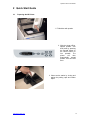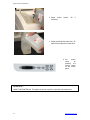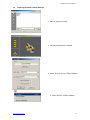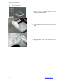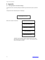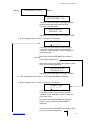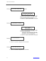
1
Spectrum Z510 User Manual April 2005 TM Spectrum Z 510 User Manual Rev F © 2004-2005 Z Corporation Part Number 09537 Spectrum Z510 User Manual USE OF EQUIPMENT Z Corporation's Equipment, and use of the Equipment, may be subject to limitations imposed under patents licensed to or owned by Z Corp., and is to be used solely for the fabrication of appearance models and prototypes using new Z Corporation-supplied consumables from Z Corporation or its authorized distributors in the original packaging. Other uses may be restricted; contact Z Corporation for further information. Consult the user's manual before operation of any Z Corporation Equipment. The Equipment may be covered by the following U.S. Patents: 5,204,055 5,340,656 5,387,380 6,007,318 6,416,850 6,610,429 6,403,002 6,375,874 5,902,441 The Equipment is designed to be used by design engineers and other professionals in the production of early-stage 3D appearance models and prototypes. The Equipment is not to be used to produce, either directly or indirectly, medical or other products that may require precise dimensions or tolerances to ensure the safe and effective operation of such products. You agree to indemnify, defend and hold Z Corporation and its officers, directors and employees harmless from and against any and all claims, losses, damages, costs and expenses resulting from any use of the Equipment other than for the production of early-stage appearance models and prototypes. If the customer has purchased all relevant casting-specific products as recommended by Z Corp. (casting-specific service contract, hardware, software, and consumables), as well as a casting license, then the customer may also utilize the Equipment to fabricate molds for casting using new Z Corporation-supplied consumables from Z Corporation or its authorized distributors in the original packaging. www.zcorp-users.com 2 Spectrum Z510 User Manual TABLE OF CONTENTS 1 2 3 4 5 6 3 Introduction .............................................................................................................................5 1.1 Overview ......................................................................................................................5 1.2 How It Works ................................................................................................................6 1.3 System Components....................................................................................................8 1.4 Printer Components .....................................................................................................9 1.5 Control Panel................................................................................................................9 1.6 Internal Components..................................................................................................10 1.7 ZD5 Powder Recycling System..................................................................................12 1.8 Spectrum Z510 Accessories and Tools .....................................................................13 1.9 ZPrint System Software .............................................................................................13 Quick Start Guide..................................................................................................................14 2.1 Preparing the 3D Printer ............................................................................................14 2.2 Preparing the Build in ZPrint Software.......................................................................16 2.3 Removing the Part .....................................................................................................17 Routine Operation .................................................................................................................18 3.1 Preparing the Build Area ............................................................................................18 3.2 Cleaning the Service Station......................................................................................20 3.3 Checking Fluid Levels ................................................................................................22 3.4 Change Print Heads...................................................................................................23 Using the ZPrintTM Software..................................................................................................27 4.1 Tips on Setting up the Build .......................................................................................27 4.2 Open or Import the File(s) ..........................................................................................28 4.3 Part Orientation ..........................................................................................................28 4.3.1 Part Containing an Opening or Hollow Area .....................................................28 4.3.2 Part Containing Overhangs ...............................................................................28 4.4 Checking Build Settings .............................................................................................29 4.5 Printing the Build ........................................................................................................30 Post Processing the Part.......................................................................................................31 5.1 Tips on Gross and Fine Depowdering .......................................................................31 5.2 Post Processing Tools ...............................................................................................31 5.3 Removing the Finished Part.......................................................................................33 5.4 Depowdering the Part ................................................................................................35 5.5 Drying the Part ...........................................................................................................36 5.6 Part Infiltration ............................................................................................................36 5.6.1 Using Paraplast X-TRA Wax .............................................................................37 5.6.2 Using Z-BondTM Cyanoacrylate .........................................................................38 5.6.3 Using Z-MaxTM Epoxy ........................................................................................39 Service Menu and Other Maintenance .................................................................................41 6.1 Unpark........................................................................................................................41 6.2 Purge Print Head........................................................................................................41 6.3 Check Powder Level ..................................................................................................41 6.4 Drop Feed Piston .......................................................................................................41 6.5 Fill Bed .......................................................................................................................41 6.6 Preheat Printer ...........................................................................................................41 6.7 Maintenance...............................................................................................................41 6.7.1 Fast Axis Lubrication .........................................................................................42 6.7.2 Slow Axis Lubrication ........................................................................................44 6.8 Piston Screws Lubrication..........................................................................................46 6.9 Bleed Air.....................................................................................................................47 6.10 Service Print Heads ...................................................................................................48 6.11 Prime Wash Line ........................................................................................................48 6.12 Stripe Test ..................................................................................................................48 6.13 Cleaning the Spreader Roller / Toggle Roller ............................................................48 6.14 Check Status ..............................................................................................................50 6.15 Report Capabilities .....................................................................................................50 www.zcorp-users.com Spectrum Z510 User Manual 6.16 Print Head Report.......................................................................................................50 6.17 View Printer Log .........................................................................................................50 6.18 Other Service Menu Items .........................................................................................50 6.19 Replace Fluid Lines with Distilled Water....................................................................51 7 Troubleshooting ....................................................................................................................53 7.1 The binder solution is being applied in erratic stripes ................................................53 7.2 ZPrint Software freezes up during the print job..........................................................53 7.3 Thin planar parts are warping ....................................................................................53 7.4 Nothing happens when I try to print ...........................................................................53 7.5 Parts are unusually weak or crumbly .........................................................................54 7.6 Printer looks like it is printing, but is not laying down binder......................................54 7.7 Air has Entered the Binder Fluid Lines.......................................................................54 7.8 Air has Entered into the Wash Fluid Line...................................................................55 7.9 Communication Errors Between Print Head and Printer............................................56 8 Spectrum System Details......................................................................................................57 8.1 System Specifications ................................................................................................57 8.2 Symbols Used ............................................................................................................58 8.3 Description of Rear Panel ..........................................................................................58 8.4 Material Storage Precautions.....................................................................................58 9 Appendix ...............................................................................................................................59 9.1 Restoring Network and Firmware Settings ................................................................59 9.2 Error Codes ................................................................................................................62 TABLE OF FIGURES Figure 1: The Printing Process ......................................................................................................6 Figure 2: The ZCorp. 3D Printer Shelling and Infrastructure Features .........................................7 Figure 3: Spectrum Z510 System Components ............................................................................8 Figure 4: Spectrum External Components ....................................................................................9 Figure 5: Control Panel..................................................................................................................9 Figure 6: Spectrum Internal Components ...................................................................................10 Figure 7: Printer Assembly with Carriage Insert..........................................................................10 Figure 8: Service Station .............................................................................................................11 Figure 9: ZD5 Powder Recycling System....................................................................................12 Figure 10: Accessories and Toolbox ...........................................................................................13 Figure 11: ZPrint Software...........................................................................................................13 www.zcorp-users.com 4 Spectrum Z510 User Manual 1 Introduction 1.1 Overview This Spectrum User Manual will speed you along the path towards quickly and inexpensively building parts. The manual contains the following sections: 1. Introduction. This section will give you an overview of the principles behind the Spectrum System; familiarize you with the terminology we will use to describe the Spectrum System; and illustrate the different parts of the printer. 2. Quick Start Guide. This section contains a short step-by-step process of how to get a print job running on your printer. For a more detailed explanation, see Sections 3, 4, and 5. 3. Routine Operation. This section will guide you through putting powder, binder solution and wash fluid in the printer, and preparing the system to print a part. 4. Using the ZPrintTM Software. This section gives you an overview of how to set up a build on the ZPrint Software. For more information about the software and its features, please refer to the ZPrint User Manual. 5. Post Processing the Part. This section guides you through removing your printed part, depowdering, and infiltrating the part with resin to improve strength and finish. It will also explain how to use the most common infiltrants available from Z Corporation. For information on other infiltrants or applications, visit the User Group Website at www.zcorp-users.com. 6. ZPrint Service Menu and Other Maintenance. This section contains instructions for keeping your printer in proper condition through regular preventative maintenance. 7. Troubleshooting. This section offers some troubleshooting tips. 8. Spectrum System Details. This section contains system specifications about the Spectrum Z510 3D Printer and material storage recommendations. 9. Appendix. This section contains useful information on how to set-up your printer and shows a list of common error codes. 10. Index. 5 www.zcorp-users.com Spectrum Z510 User Manual 1.2 How It Works The Spectrum System is based on the Massachusetts Institute of Technology’s patented 3DP™ (3D Printing) technology. The software first converts a three-dimensional design built using 3D CAD into cross-sections or slices that can be between 0.0035” – 0.004” (0.0875 - 0.1 mm) thick. The printer then prints these cross-sections one after another from the bottom of part to the top. Inside the printer there are two pistons (see Figure 1.) The feed piston is represented in the diagrams below on the left and is shown in the ‘down’ position filled with powder. The build piston is the piston on the right, shown below in the ‘up’ position. Also represented in the diagrams are the roller (drawn as a circle) and the print assembly (drawn as a square.) On the printer, the roller and the print assembly are mounted together on the gantry which moves horizontally across the build area. To begin the 3D printing process, the printer first spreads a layer of powder in the same thickness as the cross section to be printed. The print heads then apply a binder solution to the powder causing the powder particles to bind to one another and to the printed cross-section one level below. The feed piston comes up one layer and the build piston drops one layer. The printer then spreads a new layer of powder and repeats the process, and in a short time the entire part is printed. Step 1: As the gantry traverses left to right, the roller collects powder. Step 2: The roller spreads a thin layer of powder over the build piston. Step 4: As the gantry traverses right to left, the print head prints the part cross-section. Step 3: The roller discharges excess powder down the powder overflow chute. Step 5: The feed piston moves up one layer, the build piston moves down one layer, and the process is repeated. Figure 1: The Printing Process www.zcorp-users.com 6 Spectrum Z510 User Manual The printer employs several techniques to quickly build parts. First, binder solution is applied in a higher concentration around the edges of the part, creating a strong “shell” around the exterior of the part. Within parts, the printer builds an infrastructure by printing strong scaffolding within part walls with a higher concentration of binder solution. The remaining interior areas are printed with a lower saturation, which gives them stability, but prevents over-saturation, which can lead to part distortion of the part. Interior infrastructure printed at a higher saturation Other interior areas printed at lower saturation Exterior walls printed at higher saturation Figure 2: The ZCorp. 3D Printer Shelling and Infrastructure Features After printing, the part is removed from the powder bed, depowdered and dried. The part can then be infiltrated with wax, epoxy, or other materials to increase strength and durability. More information on different infiltrants can be found in Section 5.6, Infiltrating the Part. You will have the part in your hands and can start improving your design within the same day—usually within hours. Because the powder layers support the structures being printed above, the printer creates parts without support structures and can print parts with complex geometries that are impossible for other systems. There are several important characteristics of the Spectrum 3D Printer that will help you print the best parts for your intended purpose. 7 Part Placement. The software will place the parts within the build box to maximize build speed, the most important criteria for the majority of our users. The software positions the parts with the smallest dimension in the z (vertical) axis. For more information, refer to the ZPrint Software User Manual. In addition to part placement, the following other characteristics should be considered. Strength. The ultimate strength of the part will be somewhat affected by its orientation within the print box. The part will be strongest along the y-axis and the x-axis and less strong along the z-axis. This is because the cross sections are printed in continuous strips along the y or the “fast” axis (the print heads direction of travel), bands across the x or the “slow” axis (the gantry direction of travel) and laminated layers along the z-axis. (See figure 3). This discussion only applies to untreated parts; once parts are infiltrated, they uniformly take on the strength characteristics of the infiltrating material. Accuracy. The accuracy of the system depends on the materials you choose. You can employ the anisotropic scaling feature in the software to adjust for expected shrinkage and bring your parts into true scale. More information on anisotropic scaling factors can be found in the ZPrint User Manual. www.zcorp-users.com Spectrum Z510 User Manual 1.3 System Components Spectrum Z510 3D Printer ZD5 Powder Recycling System Figure 3: Spectrum Z510 System Components www.zcorp-users.com 8 Spectrum Z510 User Manual 1.4 Printer Components Figure 4: Spectrum External Components 1.5 Control Panel PLEASE NOTE: When the system is online, all buttons except the online button are disabled. Figure 5: Control Panel 9 www.zcorp-users.com Spectrum Z510 User Manual 1.6 Internal Components Figure 6: Spectrum Internal Components Figure 7: Printer Assembly with Carriage Insert www.zcorp-users.com 10 Spectrum Z510 User Manual Figure 8: Service Station 11 www.zcorp-users.com Spectrum Z510 User Manual 1.7 ZD5 Powder Recycling System Figure 9: ZD5 Powder Recycling System www.zcorp-users.com 12 Spectrum Z510 User Manual 1.8 Spectrum Z510 Accessories and Tools The Spectrum Z510 Toolkit contains parts for user maintenance and items frequently used while post processing printed parts. Figure 10: Accessories and Toolbox 1.9 ZPrint System Software ZPrint Software is the file processing tool that sends information from the user’s workstation to the Spectrum Z510. Please refer to the ZPrint User Manual for installation and use instructions. Figure 11: ZPrint Software 13 www.zcorp-users.com Spectrum Z510 User Manual 2 Quick Start Guide 2.1 Preparing the 3D Printer 1. Fill feed box with powder. 2. With the printer offline, spread powder over build area by pressing the ‘Spread’ button on the control button for four spreads. The printer will then automatically spread powder over the build area. 3. Clean service station by rinsing and wiping the parking caps and rubber wiper. www.zcorp-users.com 14 Spectrum Z510 User Manual 4. Check binder necessary. bottles. Fill if 5. Check wash fluid and waste fluid. Fill wash fluid and dispose of waste fluid. 6. Put printer online by pressing the ‘Online’ button on the control panel. Technical Tip LEAVE THE PRINTER ON! This allows the printer to perform a periodic self maintenance. 15 www.zcorp-users.com Spectrum Z510 User Manual 2.2 Preparing the Build in ZPrint Software 1. Open or import your file(s). 2. Orient and scale the file if needed. 3. Check ‘3D Print Set-up’ in ZPrint Software. 4. Press ‘3D Print’ in ZPrint Software. www.zcorp-users.com 16 Spectrum Z510 User Manual 2.3 Removing the Part 1. Wait for part to complete printing. Check software for part orientation. 2. Gross depowder the part and remove from build area. 3. Fine depowder part and post-process as needed. 17 www.zcorp-users.com Spectrum Z510 User Manual 3 Routine Operation 3.1 Preparing the Build Area 1. Preheat printer if needed. Preheating the printer will reduce the print time if the printer has not reached the required temperature. To preheat the printer, select the Preheat Printer option under the Service menu. 2. Lower feed piston by pressing down on the ‘Feed Down’ button until the feed piston automatically drops. 3. Take printer offline by pressing ‘Offline’ on the control panel. 4. Lift top cover. WARNING: Use only powder supplied by Z Corporation. Use of any other material may impact the performance and/or safety of your Spectrum System and will void warranty of equipment. 5. Raise build piston by pressing ‘Build Up’. Once build piston has stopped, press ‘Build Up’ once. You will see ‘Hold for Unload’ on the control panel. www.zcorp-users.com 18 Spectrum Z510 User Manual 6. Hold the build up button until the build piston raises. The build piston will expose the build plate holders. 7. Place build plate on top of holders. Make sure build plate is secure. Press any button on the control panel to lower the build piston. 8. Fill feed box with powder. First empty the powder from the overflow bin and then add fresh powder if needed. 9. Tamp powder and raise feed piston until powder reaches the top edge of the feed box. 19 www.zcorp-users.com Spectrum Z510 User Manual 10. Close the top cover. Fill build area with powder by pressing and holding the ‘Spread’ button on the control panel for four complete spreads. This will initiate the “Fill Bed” mode. The LCD will display “Filling bed; Online to cancel.” 11. Lift top cover and vacuum loose powder from area surrounding feed and build box. Technical Tip Keep powder containers closed when not in use to keep powder dry. Scoop powder carefully to minimize airborne powder. Make sure that you carefully vacuum up excess powder. It only takes a minute, and the tidier the machine is, the less often it will need maintenance! Carefully read the Material Safety Data Sheet for powder before use. 3.2 Cleaning the Service Station The service station cleans the array of the print heads during printing. The service station MUST be cleaned before every build. This will remove any deposits of powder. Make sure parking caps are dry before beginning the build. 1. Select “Unpark” from the Service Menu in ZPrint Software, which will move the carriage out of the parking position, allowing access to the service station. www.zcorp-users.com 20 Spectrum Z510 User Manual 2. With the service station exposed, rinse rubber parking cap with distilled water (If needed, remove rubber parking caps and rinse under running water). Wipe dry with paper towel. PLEASE NOTE: Make sure the parking caps are sitting flat in their holder. 3. Rinse rubber wiper blade with distilled water and wipe dry with paper towel. Ensure that there is no powder build up anywhere in the proximity of the rubber wiper. 4. Wipe metal spit cover with damp paper towel. 5. Close top cover and press ‘OK’ to repark on the software. 21 www.zcorp-users.com Spectrum Z510 User Manual 3.3 Checking Fluid Levels 1. Open front cabinet tray. 2. Check wash fluid level. If it is less than half full, refill wash fluid bottle. 3. Check waste fluid. If empty fluid. Empty accordance to local safety regulations. cabinet tray. it is half full, contents in or company Close front WARNING: Do not recycle waste solution. The waste is contaminated with powder and use of this waste in the Spectrum 3D Printer will clog the fluid system. Use only binder and wash fluid supplied by Z Corporation. Use of any other material may impact the performance and safety of your Spectrum System and will void the warranty. www.zcorp-users.com 22 Spectrum Z510 User Manual 4. Check binder bottles. The Spectrum Z510 is not equipped with binder level sensors. The user must check the binder levels prior to each build to ensure the Spectrum Z510 has enough to complete the build. View the binder levels through the cutout windows in the binder bottle cover on the top cover. If it is half full, fill binder bottles. PLEASE NOTE: When printing in monochrome is it still necessary to have binder in the color bottles for servicing. WARNING: If this is the first time you have added binder or the binder bottle on the Spectrum Z510 has run dry you must “Bleed Air”. Please refer to Section 6.9, Bleed Air. 3.4 Change Print Heads 1. Determine which print head needs to be changed. This can be done either by an error during printing or by reviewing the Print Head Report located under the Service menu. 2. The printer needs to be ‘Online’ before changing a print head. 3. Select ‘Change Print Head…’ under the Service menu. 23 www.zcorp-users.com Spectrum Z510 User Manual 4. Open top cover. Then open carriage cover. 5. Replace print head. 6. Close carriage cover. 7. Using a moist paper towel, wipe the alignment window located on the left side of the gantry. Then dry off with a dry paper towel. Close top cover. www.zcorp-users.com 24 Spectrum Z510 User Manual 8. Press ‘Done’ on the ZPrint Software. 9. Select ‘Auto Alignment’ from the Service menu. 10. The printer will first detect which print head(s) was changed, purge the print head of HP ink and print 60 layers of a gray base. 11. After printing a base, the printer will print out an alignment pattern, read the pattern and then adjust position as needed. 25 www.zcorp-users.com Spectrum Z510 User Manual 12. Lastly, the printer will print a bulls-eye pattern for you to confirm that all print heads have been aligned. You may wish to start a build while the print heads are aligning. By selecting to close the alignment window (clicking the ‘X’ on the upper right hand corner of the dialog box). The part will be built on top of the alignment patterns. Please Note: If you choose to begin a build before alignment has finished, you may not be able to confirm the bull’s eye pattern before printing. www.zcorp-users.com 26 Spectrum Z510 User Manual 4 Using the ZPrintTM Software This chapter will briefly explain how to set up the build, check the settings, and print. For more information about the features in the ZPrint Software, please refer to the ZPrint Software User Manual. PLEASE NOTE: If the ZPrint Software has not been installed, install the software. Instructions are located in Section 1.2 of the ZPrint Software User Manual. 4.1 Tips on Setting up the Build 27 Do not tightly pack parts into the build. Keep in mind that you will need to depowder and remove them from the build box. Allowing a little bit of room around the part so you can vacuum the powder away and get your fingers around or under it. Orient parts so delicate features are supported in the z-axis, i.e. keep the attaching feature directly below the fragile features. If a delicate feature is only supported by unprinted powder the chances of breaking that small feature during depowdering is greatly increased. When building delicate parts use the “Fixture” function to cradle the part. Raising the part 0.25” (6.4 mm) from the bottom of the build and creating a fixture under the part will produce a cradle that can be handled. The part inside the cradle can easily be transported to an oven or the depowderer. Do not enable the bleed compensation feature if you are building a part with features under 0.050" (1.27 mm). Enabling bleed compensation may reduce the feature size. To increase the strength of thin parts, you can decrease the layer thickness to 0.0035” (0.089 mm) if you are using high composite powder systems. Then choose to override the saturation values. Input the saturation values used for printing at 0.004” (0.102 mm). This increases the binder to powder ratio and wets more of the resins in the powder system. As you increase the strength of the part in this manner you are also increasing the amount of time to dry the part. Oven drying the part is recommended. www.zcorp-users.com Spectrum Z510 User Manual 4.2 Open or Import the File(s) 1. Open the ZPrint Software. The open dialog box will appear. 2. Choose the file you wish to open. 3. Click ‘Open’ or double-click the file. 4. Choose the dimensions and powder type you will be using. 5. Click ‘OK’. 6. The file will be brought into the software in a new window. 7. If you would like to add additional files to this build, choose the ‘Import’ option under the File menu. 4.3 Part Orientation 4.3.1 4.3.2 Part Containing an Opening or Hollow Area If the part has an opening or is hollow, place the opening or hollow side up. This will allow for the removal of powder during the depowdering process. Part Containing Overhangs Unsupported overhangs should be placed on the left hand-side and as close to the build plate as possible. The high definition composite powder, being extremely fine, is more fluid in the build. For increased accuracy, the software provides a fixturing feature that creates a cradle for the overhanging area. Cylindrical features will be more accurate when their axis is parallel to the z-axis. For example, if you were to print a bottle, the bottle would best be printed standing up, with the mouth of the bottle facing the top of the printer. www.zcorp-users.com 28 Spectrum Z510 User Manual 4.4 Checking Build Settings ALWAYS check build settings before printing: 1. Choose the ‘3D Print Setup’ option from the File menu (or toolbar). 2. Check that the selected printer, powder type, and powder settings for the build are correct. The software settings are the recommended values. 3. If the settings need to be changed, select ‘Override’. Press ‘OK’ to confirm. For more information on how to change the settings, please refer to the ZPrint Software User Manual. 29 It is also strongly recommended that slice viewing and collision detection (if more than one part is being printed) be used before beginning the build. These features are found under the View menu of the software. Slice viewing allows you to view the cross sections of the part to identify any errors in the file. Collision detection will scan through the slices and report the layer in which part overlapping is found. www.zcorp-users.com Spectrum Z510 User Manual 4.5 Printing the Build It is strongly recommended that the build settings be confirmed before printing. To check build settings, choose ‘3D Print Setup’ under the File menu or click on the icon located on the taskbar. After all build settings have been confirmed: 1. Choose ‘3D Print’ under the File menu. 2. A dialog box will appear asking that powder and fluid levels be checked. 3. Check off the boxes to confirm that these have been inspected before beginning the build. Once the build has begun, a dialog box will appear reporting the status of the build. www.zcorp-users.com 30 Spectrum Z510 User Manual 5 Post Processing the Part 5.1 Tips on Gross and Fine Depowdering • • • 5.2 Become familiar with where the parts are placed and how they are oriented in the build box so you do not accidentally bump or brush against a fragile part during the depowdering process. When performing the gross depowdering (removal of excess powder in the build box) do not plunge the vacuum nozzle into the powder bed. Begin at the outer perimeter of the build box, slowly work your way into the build. Hold the tip of vacuum nozzle approximately 0.25” (6.4 mm) to 0.375” (9.5 mm) away from the powder and allow the vacuum to pull the powder up. Slanting the vacuum nozzle will enable you to control the suction. This will decrease the chance of breaking a part that is hidden beneath the surface of the powder. While fine depowdering in the depowderer, always start with a low air pressure and gradually increase the pressure as the fine details and features of the part become visible. When the top and sides of the part are completely depowdered tilt the part onto one of its sides. Handle the part carefully. The part may be fragile and brittle before infiltration. If none of the sides of the part will be able to support the weight of the part you can apply a small amount of resin or epoxy to strengthen it. You want to be careful not to let any of the infiltrant come into contact with any unprinted powder that may still be on the part. Let the infiltrant dry before continuing to depowder. Post Processing Tools There are six tools included in the accessories kit that are used to assist the user with gross depowdering and cleaning of the part. 2 4 5 6 1 31 3 www.zcorp-users.com Spectrum Z510 User Manual 1. Wide Blade Utility Scraper: This part is extremely useful in moving powder from the build chamber or deck surface back into the feed chamber. 2. Polypropylene Scraper: When gross depowdering a bulky part, such as the engine block, the user may choose to carve powder away from the part instead of moving it away with either the vacuum or their hands. 3. Soft Horsehair Brush: This brush has very soft bristles and assists the user with the gross depowdering process. Brushing powder away from the part is a useful technique prior to the vacuuming step. 4. Stiff Detailing Brush: This brush has very stiff bristles, which are useful for scrubbing caked powder out of tight areas of a part. The brush is also very helpful when removing fringing from color part surfaces. 5. Stiff Handle Brush: This tool serves the same purpose as the Stiff Detailing Brush but is slightly larger and is more useful when working with a larger surface area. www.zcorp-users.com 32 Spectrum Z510 User Manual 6. Soft Acid Brush: This part can also be used to remove caked powder from hard to reach areas and the soft bristles make this brush perfect for delicate features. 5.3 Removing the Finished Part After the build is complete, remove the finished parts from the build box as follows: 1. Leave the part in the bed for approximately 30-60 minutes. Take a moment to look at the computer screen and determine exactly where parts lie in the build box. 2. Take the printer offline by pressing the ‘Online’ button and lift the top cover. 3. Press the feed down button to lower the feed piston. 33 www.zcorp-users.com Spectrum Z510 User Manual 4. Remove powder away from the buried parts, and clean powder out of the margins against the walls of the build box. 5. Without raising the build piston, begin removing powder around the part either by using the vacuum or post-processing tools. When vacuuming, hold the end of the hose on a 20° to 30° degree angle over the powder so the hose inlet is 1/4” to 3/8” above the surface of the powder. This generates enough of a draft to lift loose powder without damaging the parts. For more information about the post-processing tools, refer to Section 5.2, Post Processing Tools. 6. To gain access to the sides of the parts, raise the build piston by holding down the build up button. 7. When finished, you may remove the part by hand or press the ‘Build Up’ button on the control panel. When it stops moving, press ‘Build Up’ one more time to initiate the unload feature. The build plate will now be exposed and easy to lift off the build envelope. www.zcorp-users.com 34 Spectrum Z510 User Manual 8. Place a tray on the top of the feed area. Remove the build plate and place on the tray. The part is now ready to be fine depowdered. WARNING: When performing any vacuuming operation, use the vacuum provided as part of the Spectrum System. Vacuuming powder can generate static electricity, and use of a non-grounded vacuum will create static charges, which may affect the operation of the Spectrum System and harm the operator. 5.4 Depowdering the Part 1. Place parts inside depowdering station. 2. Turn on vacuum cleaner. 35 www.zcorp-users.com Spectrum Z510 User Manual 3. Turn on air compressor. 4. Change air pressure as needed and check pressure with hand before applying air on part. Technical Tip -The air pressure on your depowdering station is adjustable. For bulky parts, turn the air pressure up. For more delicate parts, turn the air pressure down. 5. Remove excess powder from part. 5.5 Drying the Part Although the part can be handled when it is not completely dried, the part reaches full strength when dried. Placing the part in an oven at temperatures less than 200°F (93oC) for 2-4 hours will dramatically increase the strength of the part. This is only recommended for high definition composite powders. If using the removable build plate, remove the part from the removable build plate before placing in the oven. 5.6 Part Infiltration All parts can be infiltrated with a variety of resins to produce a range of material properties. As an early stage design tool, it may not be necessary to infiltrate the parts at all. However, the true versatility of the Spectrum Z510 System is derived from the variety of material properties that can be achieved by applying one of our infiltration materials to parts that will be exposed to a variety of product testing environments. For additional information on how Z Corp. customers are utilizing our line of infiltration products visit our user group website at www.zcorp-users.com. www.zcorp-users.com 36 Spectrum Z510 User Manual INFILTRANT Wax Z-BondTM Cyanoacrylate Z-MaxTM Epoxy MATERIAL SYSTEM High Composite Material High Composite Material High Composite Material APPLICATION Dip Brush or Drizzle Spray or Brush For an updated list, please visit the Z Corp. Users Website at www.zcorp-users.com 5.6.1 Using Paraplast X-TRA Wax Paraplast X-Tra is a low viscosity, general purpose, infiltration wax formulated to melt at very low temperatures (122°F or 50°C) and strengthen parts. This material cures rapidly and enhances the vibrancy of color parts. PARAPLAST is available in a case of eight 2.2 lb. (1 kilogram) bag of chips. Paraplast X-Tra Wax can be used in both the ZW3 and ZW4 Waxers. SAFETY PRECAUTIONS • Liquid wax is hot and may cause burns. Follow all manufacturer recommended safety precautions for your dip tank prior to use. • Wear gloves when handling hot parts. GENERAL APPLICATION NOTES • Parts should be dried in an oven at 100°F (38°C) prior to infiltrating with wax for deeper wax penetration. • If the part is bulky, you may preheat it at 150°F (66°C) for up to 30 minutes. • Soak part in liquid wax tank (follow all tank manufacturer’s instructions). • Remove infiltrated part from dip tank. • Place part in an oven at 150°F (66°C) until the wax has penetrated or melted off your part (usually around 15 minutes). • Be aware that these are simple guidelines. Your specific applications may require additional steps. CURING INFORMATION • 37 Allow your parts to cool after removal from the oven until the part is no longer warm to the touch. www.zcorp-users.com Spectrum Z510 User Manual 5.6.2 Using Z-BondTM Cyanoacrylate Z-Bond cyanoacrylate is an extremely fast setting, low viscosity, general-purpose infiltration resin. This resin is designed to rapidly strengthen parts. Z-Bond is a one part, user friendly, noodor, non-blooming resin that may eliminate the need for special ventilation. This resin is easily sanded and enhances the vibrancy of color parts. Z-Bond 100 is available in 3.5 ounce bottles and 24 ounce spray bottles. SAFETY PRECAUTIONS • • • • • Do not use or handle this product until the Material Safety Data Sheet has been read and understood. Wear lab coat, gloves (we recommend Nitrile Examination Gloves), face shield or goggles. Face shield is required if spraying. Apply in ventilated hood. Specialized containers recommended for dispensing and application. System for avoiding spills: Catch pan, waxed paper, or plastic drop cloth. Label disposal materials. Wear dust mask when sanding finished parts. GENERAL APPLICATION NOTES • • • • Part should be fully dried before applying resin. Resin reacts with water and produces heat. If the part is not dried, it will heat up the part and produce gas that may be an irritant to the mucous membranes. Material can be brushed or dripped. Material will penetrate between 0.08 - 0.12 inches (2–3 mm). Do not over apply the material, as it will pool off the part during cure cycle. CURING INFORMATION • • • The part should be placed on a non-stick material (wax paper, Teflon, etc.) to prevent it from adhering to the surface it is sitting on while curing. Wear gloves when handling the parts to avoid contact with uncured resin. Parts will attain full strength in two minutes. TIPS • • Always infiltrate the most delicate features of the part first. Z-Bond resin gives almost immediate strength to the area of the part that has been infiltrated. As you handle the areas of the part that have been infiltrated it will be less likely to break it. Try to avoid infiltrating the part by applying Z-Bond resin from spot to spot. Pick a good starting place hold that area upward relative to the rest of the part. With your free hand, place the tip of the Z-Bond bottle against the part and allow the cyanoacrylate (CA) to flow from the bottle. It is important that the CA flows at a uniform rate making it easier for you the judge how quickly it will flow from the tip of the bottle before it wicks into the part. By seeing how quickly it wicks into the part you will be able to judge where and how quickly to move the tip of the bottle while applying the CA, being sure not to apply the CA to the same place more than once. www.zcorp-users.com 38 Spectrum Z510 User Manual 5.6.3 Using Z-MaxTM Epoxy SAFETY PRECAUTIONS • • • • • Wear lab coat, gloves (we recommend PVC Examination Gloves), face shield or goggles. Face shield is required if spraying. Apply in ventilated hood. Use specialized containers recommended for dispensing and application. A system for avoiding spills includes: Catch pan, waxed paper, or plastic drop cloth. Label disposal materials. Wear dust mask when sanding finished parts. Read the Material Safety Data Sheet for Z-Max prior to the use of this material. MIXING INSTRUCTIONS • When using the 250 gm Z-Max kit simply pour the entire contents of the Z-Max Hardener container into the Z-Max Resin container and mix the two parts thoroughly for two minutes prior to application. If less than 250 grams is desired, follow the instructions for mixing by weight or volume. • Mix 100 parts Z-Max Resin to 37 parts Z-Max Hardener by weight or 100 parts Z-Max Resin to 41 parts Z-Max Hardener by volume. Mix the two parts thoroughly for two minutes before application. The material has a working time of 35 minutes in a 425 gram mass. Please be aware of the gel time while preparing quantities of material as the gel time decreases as the quantity of material increases. It is recommended not to mix quantities over 425 grams. GENERAL APPLICATION NOTES • • • • • Material can be brushed or sprayed. Material will penetrate between 0.079-0.28 inches (2 – 7 mm). Material will pool off the part during curing, if it is over-applied. Better penetration depth is achieved by applying several light coats of material. Allow all mixed materials to cure prior to disposal. SPRAYING INSTRUCTIONS • • • • • • • 39 Use Gravity Feed High Volume Low Pressure Sprayer (Z Corp. Part # 14206). We recommend Devilbiss Sprayer with 14 – 18 mm tip. Other sprayers are compatible, however the use of a HVLP sprayer will minimize the amount of overspray generated. The Devilbiss Sprayer is available with disposable canister liners (Z Corp. Part # 14207). and will minimize the amount of cleanup. Have the sprayer, parts and materials ready before mixing the resin. Mix resin and pour into the disposable liner in the canister. Always spray in a vented hood. Use of a respirator is also recommended. Spray resin between 15 – 20 psi. When finished, remove the disposable liner and clean sprayer with ethyl alcohol or acetone. Remove the tip and thoroughly clean by hand to avoid resin build up. (Cleanup takes approximately 15 minutes). www.zcorp-users.com Spectrum Z510 User Manual CURING INFORMATION • • • • • • Allow the part to cure for 1 hour at ambient temperature to avoid discoloration prior to placing in the oven for accelerated cure. The resin can be cured at an accelerated rate in an oven. The oven must be vented. Ventilation designs need to meet each customer’s respective governmental health and safety requirements. A reference frequently used by U.S. firms to comply with OSHA regulations is the American Conference of Governmental Industrial Hygienists Industrial Ventilation Manual. At 160°F (71 °C) your part will reach full strength in 2 hours. The part should be placed on a non-stick, material (wax paper, Teflon, etc.) to prevent it from adhering to the surface it is sitting on while curing. Wear gloves when handling the parts when they are still at an elevated temperature. Parts will attain full strength and be safe to handle once they cool to room temperature. The resin will cure at room temperature after 24 hours. TIPS • • If the part has delicate features, infiltrate them last as the feature will be less strong after being infiltrated until the epoxy begins to cure. This will decrease the chance the feature will break from the part if nudged or bumped. If the part has multiple delicate features or it is impossible to handle the part without breaking a feature you may infiltrate these features only. Allow the Z-Max and Z-Snap epoxy to cure. Then infiltrate the rest of the part. This will add time to post-processing the part but it ensures that you have a good strong part without any fractures. For more information on the uses of Z-Max epoxy, please refer to the technical data sheet that can be found on the User Group Website at www.zcorp-users.com. www.zcorp-users.com 40 Spectrum Z510 User Manual 6 Service Menu and Other Maintenance The ZPrint service menu is the user’s primary interface from the desktop when performing routine maintenance functions on the Spectrum Z510 3D Printer. 6.1 Unpark Unpark moves the carriage from its parked position, in the service station, allowing the user to freely move the gantry and carriage in order to perform routine cleaning. 6.2 Purge Print Head New print heads will be automatically purged of ink when ‘Auto Alignment’ is selected. If the user wishes to manually start a purge cycle, there are two options: Purge All Print Heads will initiate a purge cycle for all print heads. Purge New Print Heads will initiate a purge cycle for new print heads only. 6.3 Check Powder Level ‘Check Powder Level’ will see if the Spectrum Z510 currently has enough powder in the feed piston to complete the build currently active in ZPrint based on the feed pistons current position. 6.4 Drop Feed Piston ‘Drop Feed Piston’ will drop the feed piston to its lowest position from the desktop enabling the user to easily add additional powder or begin gross depowdering. 6.5 Fill Bed ‘Fill bed’ initiates a cycle that will prepare the build piston for printing by automatically spreading powder from the feed piston to the build. 6.6 Preheat Printer ‘Preheat Printer’ will activate the heater in the Spectrum Z510 and heat the build area to a predetermined temperature based on the material being used. 6.7 Maintenance The ‘Maintenance’ feature keeps a record of the distance travel by the fast axis, slow axis and pistons. This is an indicator for the user as to whether or not the Spectrum Z510 requires lubrication. The ZPrint Software will prompt the user when maintenance of these items is required. The following sub-sections detail the instructions for lubrication when the need arises. 41 www.zcorp-users.com Spectrum Z510 User Manual 6.7.1 Fast Axis Lubrication 1. Assemble grease gun as instructed on packaging. 2. Unpark the gantry by choosing ‘Unpark’ under the Service menu. 3. Open top cover. 4. Wipe fast axis rails of residue with a dry paper towel. www.zcorp-users.com 42 Spectrum Z510 User Manual 5. Place grease gun on grease fitting on carriage and squeeze once. 6. Wipe excess grease off with a dry paper towel. 7. Move carriage back and forth manually to distribute the grease. Close top cover. 43 www.zcorp-users.com Spectrum Z510 User Manual 6.7.2 Slow Axis Lubrication 1. Assemble grease gun as instructed on packaging. 2. Select ‘Unpark’ under the Service menu. 3. Open top cover. 4. Wipe off slow axis rail. www.zcorp-users.com 44 Spectrum Z510 User Manual 5. Locate the two grease fittings located behind the gantry. Manually move gantry if needed to gain access to grease fittings. 6. Engage the grease gun into the fittings and squeeze once. 7. Wipe of excess grease with a dry paper towel. 8. Close top cover. 9. With the printer offline, press the ‘Spread’ button on the control panel to distribute the grease. 45 www.zcorp-users.com Spectrum Z510 User Manual 6.8 Piston Screws Lubrication 1. Lower feed and build pistons all the way down. 2. Open front cabinet tray. 3. Locate piston screws and apply grease onto the pistons from top to bottom. 4. Use your finger to distribute grease throughout pistons. Close front cabinet tray www.zcorp-users.com 46 Spectrum Z510 User Manual 6.9 Bleed Air ‘Bleed Air’ moves the carriage to the front of the Spectrum allowing easy access to the carriage. Bleed air should be performed on initial machine setup and whenever air enters into he binder fluid lines. Air in the binder fluids system will cause premature print head death. 1. Select ‘Bleed Air’ under the Service menu. 2. Open carriage cover and remove print heads. 3. Use syringe (found in toolbox) to draw water through each fluid line. Draw fluid through each line until it is clear (minimum of 50 cc). 4. Close carriage cover, and top cover, and ‘Cancel’ in the software. 47 www.zcorp-users.com Spectrum Z510 User Manual 6.10 Service Print Heads ‘Service Print Heads’ will initiate a standard service on the print heads. 6.11 Prime Wash Line ‘Prime Wash Line’ will remove any air from the wash fluid pumping system. This should be performed upon initial machine setup and any time the wash fluid is allowed to run dry. 6.12 Stripe Test Authorized Z CORPORATION service personnel use ‘Strip Test’ to aid in troubleshooting. 6.13 Cleaning the Spreader Roller / Toggle Roller 1. Open top cover. 2. Remove all powder from build envelope. 3. Lower the top cover and put the printer offline. 4. Lower build piston all the way down. www.zcorp-users.com 48 Spectrum Z510 User Manual 5. Put printer offline, and lift top cover. 6. Move gantry manually over the build area. 7. Put online. printer 8. Select ‘Toggle Roller On/Off’ from Service menu. 9. Using a moist paper towel, wipe under the gantry making sure to remove all powder residue. Dry the area with a paper towel. Select Toggle Roller On/Off to turn off the roller. 49 www.zcorp-users.com Spectrum Z510 User Manual 6.14 Check Status ‘Check Status’ prompts a window that states information that may be valuable to a service provider such as firmware version and compile date as well as the current position of the feed and build pistons. 6.15 Report Capabilities ‘Report Capabilities’ is a tool used by authorized Z Corporation service provider to evaluate the logical state of the Spectrum. 6.16 Print Head Report ‘Print Head Report’ is a useful tool for identifying how old each print head is. The user can prompt “Print Head Report’ while working in ZPrint to identify if any or all of the print heads require changing. 6.17 View Printer Log ‘View Printer Log’ is a text file stored on the Spectrum Z510 that stores use information, error codes, and any event that occurs. You may be asked by your service provider to save the log and submit it as a part of the trouble shooting process. There is no propriety information about the parts printed in the printer log. 6.18 Other Service Menu Items The other service menu items are to be used only under the direction of an authorized Z Corporation service provider. Incorrect usage of these items will result in inoperable machine. www.zcorp-users.com 50 Spectrum Z510 User Manual 6.19 Replace Fluid Lines with Distilled Water If the printer will not be in use for more than two weeks, replacing all the fluid lines with distilled water will prevent binder from coagulating in the fluid lines. 1. Remove binder from bottle and place in an airtight container. 2. Rinse out binder bottle. 3. Fill binder bottle half way full with distilled water. 4. Select ‘Bleed Air’ under the Service menu. 5. Open carriage cover and remove print heads. 6. Use syringe (found in toolbox) to draw water through each fluid line. Draw fluid through each line until it is clear (minimum of 50 cc). 51 www.zcorp-users.com Spectrum Z510 User Manual 7. Close carriage cover, and top cover, and ‘Cancel’ in the software. www.zcorp-users.com 52 Spectrum Z510 User Manual 7 Troubleshooting 7.1 The binder solution is being applied in erratic stripes If the binder appears to be applied in fragmented stripes, check the following: 1. Rinse the squeegee clear of any debris. 2. Make sure binder supply is full. If this does not correct the problem, your print heads may be worn out. Replace the print heads as outlined above in Section 3.4, Changing the Print Heads. 7.2 ZPrint Software freezes up during the print job. Exit the software by pressing Ctrl_Alt_Delete. Check to see if the software is frozen. Complex parts can take some time to load, render, and compute slices during printing. Look for excessive disk activity which may indicate lack of RAM. If it is frozen, choose End Task from the Task Manager, then restart the software. You may choose to go to the Detailed Log Report under the View menu for the last layer printed for that build and continue from the last printed layer. 7.3 Thin planar parts are warping In general, warping is caused by uneven drying of parts. By adjusting print orientation and drying time, warping can be minimized. You can take steps to ensure that drying is occurring evenly by: 7.4 • Reorienting your part within the build box. If a thin planar surface of a part lies flat along the top of the build box, the broad exposed area may dry unevenly and bow towards the top. Reorient the part so that the thin planar surface lies perpendicular to the top of the build box. • Ensure that you are not over-drying the part. Reduce drying time to a minimum. Refer to the guide in Section 5.5, Drying the Part to select a drying time. • Decreasing the layer thickness without proportionally changing the minimum and maximum saturations will over saturate the part causing it to warp and may also cause individual layers to curl during printing. Nothing happens when I try to print • Is the network connection connected properly? Remove the cord and carefully reinstall. Reboot the Printer. The LCD will display ‘Spectrum Z510’ when booting. It will then display ‘Use Serial’ if a network connection is not found. To restore network settings, see Section 9.1, Restoring Network and Firmware Settings. • Are any of the lights on the control panel illuminated? If the control pad illuminates but nothing happens after that, shut the machine off and turn it back on again. The machine should come online. But if it does not, please contact your authorized Z Corporation Service Provider. 53 www.zcorp-users.com Spectrum Z510 User Manual 7.5 Parts are unusually weak or crumbly • Is the data file known to be without errors? If the *.stl file is not near perfect you will have problems printing the part. Open the file in the software and inspect it layer by layer to ensure there are no gaps and the part does not overlap other parts. • Is there enough binder in the feed bottles? When you start the build, a reminder box will pop up asking you to check if there is enough binder in the feed bottles. If you plan to start a large build make sure binder bottles are full. • Is the saturation too low? If your parts are unusually crumbly, check to make sure your saturation levels are not set too low for this type of part. Return to working with the default saturation values for the material type. If this does not work, please contact your authorized Z Corporation Service Provider. 7.6 Printer looks like it is printing, but is not laying down binder If you are using bleed compensation, it is not uncommon for the printer to move and lay down little or no binder for the first few layers of a part. As you begin printing, carefully watch the SPECTRUM Printer to see if it is printing normally. It may be that the print heads are not properly seated in the carriage. This can cause a bad connection with the temperature sensor and the print heads will overheat. Prolonged periods of attempting to print without binder flow will damage the print head. You will need to replace the print heads. 7.7 Air has Entered the Binder Fluid Lines When removing binder by disconnecting airlines from binder bottles or if binder runs out while printing air may enter the fluid lines. Air in the fluid lines will result in the early print head mortality. Air can be easily detected by looking to see if there are air bubbles in the fluid line. To remove air from the fluid lines, follow the instructions below: 1. Select the ‘Bleed Air’ function under the Service menu. Press ‘Start’ to initiate bleed air function. 2. Insert the syringe into the septum and let the syringe fill until there are no more air bubbles. www.zcorp-users.com 54 Spectrum Z510 User Manual 3. Remove syringe and place on a paper towel to prevent binder from dripping. 4. Empty the syringe into a waste container. PLEASE NOTE: Dispose of binder fluid in accordance to company, local, and state regulations. 5. Press ‘Cancel’ to complete bleed air function. 6. After reinserting print heads, close the carriage cover, and top cover. Then run ‘Auto Alignment’ from the Service menu. 7.8 Air has Entered into the Wash Fluid Line You will need to use the ‘Prime Wash Fluid’ feature when there is no wash fluid or air has entered the fluid line. This can occur in a few instances such as when first installing the Printer, when running out of wash fluid, or when the connection to the fluid line has been disconnected. Air can be easily detected by looking to see if there are air bubbles in the fluid line. To remove air from the fluid line, follow the instructions below: 1. Place printer online. 2. Select ‘Prime Wash Line’ under the Service menu. 3. Select ‘Start’. 55 www.zcorp-users.com Spectrum Z510 User Manual 4. The progress bar will close when priming is completed. 7.9 Communication Errors Between Print Head and Printer In general, there is no need to clean the pogo pins upon replacing the print heads. At times, they may need to be cleaned due to errors in communication between the print head and printer (such as when receiving Print Head errors) or when it is dirty. To clean the pogo pins, follow the instructions below: 1. Use the alcohol swabs which can be ordered from Z Corporation (part number 12073). 2. Remove the alcohol swab from the packaging. And crush the plastic casing to release alcohol into the swab. 3. Unpark the gantry and move gantry manually towards the front of the printer.. 4. Open the carriage remove print head. cover and 5. Wipe the pogo pins and reinsert print head. 6. Close the carriage cover and repark gantry. www.zcorp-users.com 56 Spectrum Z510 User Manual 8 Spectrum System Details 8.1 System Specifications Dedicated power outlet requirements 100-120 VAC 50-60Hz, 15A max -or220-240 VAC 50/60Hz, 7A max Network Ethernet 10/100 base T Temperature 68-85° F. (20-30° C) Relative Humidity 20-60%, non-condensed Weight 470 lbs. (210 kg) Spectrum Z510 Dimensions Cover Closed 42” x 31.25” x 50.5” (107cm x 79cm x 128cm) Cover Open 42” x 31.25” x 73” (107cm x 79cm x 185cm) Lithium Battery: Internal to the SPECTRUM 3D Printer is a lithium coin cell type battery. This may be any one of the following: Type: CR2032, either Maxell, Panasonic, Renata, Sanyo or Sony. PLEASE NOTE: This battery is not in a user accessible area and is not user replaceable. The expected lifetime of the battery is in excess of five years. Replacement will be handled by your Z Corporation customer service representative. FCC Notice: Note: this equipment has been tested and found to comply with the limits for a Class A digital device, pursuant to part 15 of the FCC rules. These limits are designed to provide reasonable protection against harmful interference when the equipment is operated in a commercial environment. This equipment generates, uses, and can radiate radio frequency energy and, if not installed and used in accordance with the instruction manual, may cause harmful interferance to radio communications. Operation of this equipment in a residential area is likely to cause harmful interference in which case the user will be required to correct the interference at his own expense. CENELEC Class A Warning: Note: this equipment has been tested and found to comply with the limits for a Class A digital device, pursuant to EN 55022. Class A devices are for office and light industrial environments, and are not generally suitable for home use. WARNING: This is a Class A product. In a domestic environment this product may cause radio interference in which case the user may be required to take adequate measures. 57 www.zcorp-users.com Spectrum Z510 User Manual 8.2 Symbols Used This is the international symbol for ‘warning’ or ‘caution’. It indicates the need to consult your manual for further information. This symbol is in two places on the SPECTRUM 3D Printer. 1. It is used on the rear, lower left to call your attention to the fact that only trained personnel should open the SPECTRUM 3D Printer rear cover. None of the normal operation procedures described in this manual require you to remove this cover. If it is being opened to lubricate the bearings, the printer should be turned off and unplugged prior to removing the cover. 8.3 Description of Rear Panel Serial Port Connection: This is an RS-232 serial port for data transfer to and from the ZPrint software. The Spectrum Printer uses 115k baud and has the same pin out as a standard PC compatible computer. The connection to the Windows computer running the software requires a 9 pin to 9 pin null modem cable (also known as a ‘laplink’ cable). This cable is supplied with your SPECTRUM System; if a replacement is required, order Z Corporation part #10267. Diagnostic Connections (Video and keyboard): These connections are used while servicing your SPECTRUM System. Nothing should be connected to them in normal operation. The diagnostic video connection is standard VGA output video. The keyboard connection is PS/2 style compatible. Ethernet Connector – The Ethernet connector allows the printer to be network compatible. For more information contact the Z Corporation Service Department at (781)852-5050 or via email at [email protected]. 8.4 Material Storage Precautions Review the Material Safety Data Sheets (MSDS) carefully before using any Z Corporation materials. Material Powder Binder and Wash Fluid Print Head Infiltrants Storage Usage Store powder on pallets in a cool, dry, ventilated area away from sources of heat, moisture, and incompatible materials. Keep containers tightly closed. Use of powder in environments with more than 30% relative humidity will affect powder performance. Store in cool, dry place, away from sun. Keep tightly capped. Store in cool, dry place, away from sun. Store in cool, dry place, away from sun. Keep tightly capped. Binder and wash fluid are NOT recyclable. www.zcorp-users.com For more information, visit the User Group Website at www.zcorp-users.com. 58 Spectrum Z510 User Manual 9 Appendix 9.1 Restoring Network and Firmware Settings Configuration mode is entered by holding the ONLINE key pressed when the printer is powered up. Configuration mode is indicated by the LCD displaying: NETWORK SETTINGS Main menu consists of 5 selections: NETWORK SETTINGS RESTORE FIRMWARE DIAGNOSTIC MODE SAVE AND EXIT DISCARD AND EXIT < Build UP > and < Build DN > keys are used to select an item to edit. When desired function is displayed, < Feed UP > key will select the item, and the LCD display will change. 59 www.zcorp-users.com Spectrum Z510 User Manual Selecting NETWORK SETTINGS displays: NETWORK SETTINGS USE NETWORK? YES < Build UP > and < Build DN > keys toggle YES/NO Note: NO means the serial port will be used < Feed UP > key will display: DHCP/STATIC IP USE DHCP? YES < Build UP > and < Build DN > KEYS toggle YES/NO If “NO” is displayed, and < Feed UP > is selected, LCD displays: IP ADDRESS 0. 0. 0. 0. < Feed UP > key will move the cursor to the right. < Feed DN > key will move the cursor to the left. < Build UP > and < Build DN > keys will change the value at the cursor. If the cursor is at the RIGHTMOST field, and the < Feed UP > Key is pressed, displayed is: If the cursor is at the LEFTMOST field, and the < Feed DN > key is pressed, displayed is: DHCP/STATIC IP: USE DHCP? NO < Build UP > and < Build DN > keys toggle YES/NO If “YES” is displayed, and < Feed UP > is selected, MAIN MENU is displayed If “NO” is displayed, and < Feed UP > is selected, LCD displays: SUBNET MASK 0. 0. 0. 0. < Feed UP > key will move the cursor to the right. < Feed DN > key will move the cursor to the left. < Build UP > and < Build DN > keys will change the value at the cursor. If the cursor is at the RIGHTMOST field, and the < Feed UP > key is pressed, the MAIN MENU is displayed. If the cursor is at the LEFTMOST field, and the < Feed DN > key is pressed, displayed is: www.zcorp-users.com 60 Spectrum Z510 User Manual Selecting RESTORE FIRMWARE displays: RESTORE FIRMWARE RESTORE FIRMWARE? NO < Build UP > and < Build DN > keys toggle YES/NO Note: YES means the printer will use the firmware previously to that which was just loaded. If < Feed UP > is pressed, MAIN MENU is displayed Selecting DIAGNOSTIC MODE DIAG MODE? DIAG MODE? NO < Build UP > and < Build DN > keys toggle YES/NO Note: NO is normal operation. YES will skip rezero (fast and slow axis, and pistons) for the current session, also causes the pistons to rezero on next powerup. If < Feed UP > is pressed, MAIN MENU is displayed. Selecting SAVE AND EXIT If < Feed UP > is pressed, configuration menu terminated. Selecting DISCARD AND EXIT If < Feed UP > is pressed, configuration menu terminated. 61 www.zcorp-users.com Spectrum Z510 User Manual 9.2 Error Codes PLEASE NOTE: %d and %x are place holders for numbers corresponding either to print head number or a value. Error Code 1000, 1001, 1003, 1004, 1005, 1006, 1007, 1009, 1010, 1802, 1905, 2303, 2304, 2305, 2400, 40006, 40007, 40008, 40204, 40205, 40207, 40208, 40800, 40801, 40802, 40901, LCD Display PRINTHEAD ERROR) PRINTHEAD POWER FAIL) PRINTHEAD %d ERROR) PRINTHEAD POWER FAIL) PRINTHEAD %d ERROR) PRINTHEAD %d OVERTEMP) PRINTHEAD POWER FAIL) PRINTHEAD POWER FAIL) PRINTHEAD %d ERROR) USE SERIAL PORT) LAYER TOO BIG) AXIS %d ERROR) AXIS %d ERROR) AXIS %d ERROR) AXIS %d REZERO ERROR) CLEAN SENSOR WINDOW) ALIGNMENT FAILED) ALIGNMENT FAILED) MOTOR DRIVE OVERLOAD) MOTOR DRIVE OVERLOAD) 24V FAIL) MOTOR DRIVE OVERLOAD) PRINTHEAD %d ERROR) HEADCARD POWER FAIL) PRINTHEAD %d NOT HP11) TEMP SENSOR FAILED) www.zcorp-users.com 62 Spectrum Z510 User Manual INDEX 3D Print, 30 Accuracy, 7 Air in Fluid Lines, 54 Air in Wash Fluid Line, 55 Alcohol Swabs, 56 Alignment Window, 24 Auto Alignment, 25 Bleed Air, 47, 51, 54 Build Open File, 28 Build Settings 3D Print Setup, 29 Override, 29 Change Print Heads, 23 Clean Pogo Pins, 56 Clean Roller, 48 Collision Detection, 29 Control Panel, 9 Error Codes, 62 External Components, 9 File Import, 28 Open, 28 Fill Bed, 20 Fill Feed Piston, 19 Firmware Settings, 59 Fluid Levels, 22 Fluid Lines Air, 54 Fluid Lines Clean Out, 51 Grease Piston Screws, 46 Import File, 28 Infiltrants Wax, 37 Z-Bond Cyanoacrylate, 38 Z-Max Epoxy, 39 Internal Components, 10 Maintenance Change print heads, 23 Clean Roller, 48 Fluid lines with distilled water, 51 Grease Piston Screws, 46 Massachusetts Institute of Technology, 6 Material Storage, 58 NetworkSettings, 59 Open File, 28 Parking Caps, 21 63 Part Orientation Circular Features, 28 Hollow Area, 28 Opening, 28 Overhangs, 28 Part Placement, 7 Part Removal, 33, 35 Parts Crumbly, 54 Warping, 53 Weak, 54 Piston Screws, 46 Pogo Pins, 56 Post Processing, 31 Tools, 31 Preheating, 18 Prime Wash Line, 55 Print Heads Change, 23 Printer Assembly, 10 Printer Error Communication Error - Print Head and Printer, 56 Printing Problems, 53 Printing Process, 6 Printing the Build, 30 Removing Part, 33 Rubber Wiper Blade, 21 Service Station, 11, 12 Clean, 20 Shelling, 7 Spit Cover, 21 Strength, 7 Striping of Binder Solution, 53 System Components, 8 System Details, 57 Tamp powder, 19 Tools Post Processing, 31 Wax, 37 Z-Bond, 37 Z-Max, 37 ZPrint Software Collision Detection, 29 Install, 27 Printing, 30 www.zcorp-users.com