1
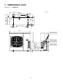
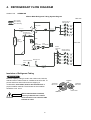
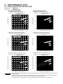
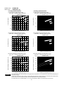
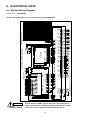
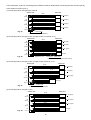
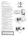
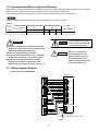
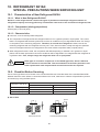
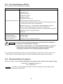
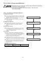
TECHNICAL & SERVICE MANUAL
NOV.2003
OUTDOOR UNIT: AE4MI91AH
Destination: General area (50Hz)
Europe (50Hz)
Australia (50Hz)
General area (60Hz)
DC INVERTER MULTI-SYSTEM AIR CONDITIONER
Capacity
9.0 kW
Indoor Model No.
Product Code No.
AE4MI91AH
4-room multi Outdoor unit
< Combined Indoor Units >
●Wall mounted type
AWMI28AHL
AWMI38AHL
AWMI50AHL
AWMI70AHL
NOTE
1. How these units may be combined is given in
the Unit Combination Tables in the Appendix.
2. Be sure to operate the air conditioning
system only when 2 or more indoor units
have been installed. If operated with only a
single unit installed, the returning fluid to the
compressor may cause a malfunction.
AE4MI91AH
IMPORTANT
These air conditioners employ new
refrigerant R410A.
Pay special attention when
servicing the unit.
W
When Transporting
Important!
Please Read Before Starting
Be careful when picking up and moving the indoor and
outdoor units. Get a partner to help, and bend your
knees when lifting to reduce strain on your back. Sharp
edges or thin aluminum fins on the air conditioner can
cut your fingers.
This air conditioning system meets strict safety and
operating standards. As the installer or service person,
it is an important part of your job to install or service the
system so it operates safely and efficiently.
When Installing…
For safe installation and trouble-free operation, you
must:
…In a Ceiling or Wall
Make sure the ceiling/wall is strong enough to hold the
unit’s weight. It may be necessary to construct a strong
wood or metal frame to provide added support.
● Carefully read this instruction booklet before
beginning.
● Follow each installation or repair step exactly as
shown.
…In a Room
Properly insulate any tubing run inside a room to
prevent “sweating” that can cause dripping and water
damage to walls and floors.
● Observe all local, state, and national electrical codes.
● Pay close attention to all warning and caution notices
given in this manual.
WARNING
CAUTION
…In Moist or Uneven Locations
Use a raised concrete pad or concrete blocks to
provide a solid, level foundation for the outdoor unit.
This prevents water damage and abnormal vibration.
This symbol refers to a hazard or
unsafe practice which can result
in severe personal injury or
death.
…In an Area with High Winds
Securely anchor the outdoor unit down with bolts and a
metal frame. Provide a suitable air baffle.
This symbol refers to a hazard or
unsafe practice which can result
in personal injury or product or
property damage.
…In a Snowy Area (for Heat Pump-type Systems)
Install the outdoor unit on a raised platform that is
higher than drifting snow. Provide snow vents.
If Necessary, Get Help
When Connecting Refrigerant Tubing
These instructions are all you need for most installation
sites and maintenance conditions. If you require help
for a special problem, contact our sales/service outlet
or your certified dealer for additional instructions.
• Use the flare method for connecting tubing.
• Apply refrigerant lubricant to the matching surfaces
of the flare and union tubes before connecting them,
then tighten the nut with a torque wrench for a leakfree connection.
In Case of Improper Installation
The manufacturer shall in no way be responsible for
improper installation or maintenance service, including
failure to follow the instructions in this document.
• Check carefully for leaks before starting the test run.
When Servicing
• Turn the power off at the main power box (mains)
before opening the unit to check or repair electrical
parts and wiring.
Special Precautions
WARNING
When Wiring
• Keep your fingers and clothing away from any
moving parts.
ELECTRICAL SHOCK CAN CAUSE
SEVERE PERSONAL INJURY OR
DEATH. ONLY A QUALIFIED,
EXPERIENCED ELECTRICIAN SHOULD
ATTEMPT TO WIRE THIS SYSTEM.
• Clean up the site after you finish, remembering to
check that no metal scraps or bits of wiring have
been left inside the unit being serviced.
Others
• Do not supply power to the unit until all wiring and
tubing are completed or reconnected and checked.
CAUTION
• Highly dangerous electrical voltages are used in this
system. Carefully refer to the wiring diagram and
these instructions when wiring. Improper connections
and inadequate grounding can cause accidental
injury or death.
• Ventilate any enclosed areas when installing or
testing the refrigeration system. Escaped refrigerant
gas, on contact with fire or heat, can produce
dangerously toxic gas.
• Confirm upon completing installation that no
refrigerant gas is leaking. If escaped gas comes in
contact with a stove, gas water heater, electric room
heater or other heat source, it can produce
dangerously toxic gas.
• Ground the unit following local electrical codes.
• Connect all wiring tightly. Loose wiring may cause
overheating at connection points and a possible fire
hazard.
• Do not install only on a single indoor unit.
i
Table of Contents
Page
1. OPERATING RANGE ............................................................................................................................... 1
2. SPECIFICATIONS
2-1. Unit Specifications .......................................................................................................................... 2
2-2. Major Component Specifications.................................................................................................... 3
2-3. Other Component Specifications.................................................................................................... 4
3. DIMENSIONAL DATA............................................................................................................................... 5
4. REFRIGERANT FLOW DIAGRAM .......................................................................................................... 6
5. PERFORMANCE DATA
5-1. Performance Charts (4-room multi) ............................................................................................... 7
6. ELECTRICAL DATA
6-1. Electric Wiring Diagram .................................................................................................................. 11
7. INSTALLATION INSTRUCTIONS
7-1. Indoor Unit ......................................................................................................................................
7-2. Outdoor Unit ...................................................................................................................................
7-3. Diagram of Outdoor Unit Installation ..............................................................................................
7-4. Recommended Wire Length and Diameter ....................................................................................
7-5. Wiring System Diagram..................................................................................................................
12
14
15
16
16
8. FUNCTIONS
8-1. Defrost Detection and End ............................................................................................................
8-2. Current Control ..............................................................................................................................
8-3. Low Start Current ..........................................................................................................................
8-4. Compressor Temperature Control .................................................................................................
8-5. Outdoor Fan Control ......................................................................................................................
8-6. Control at HEAT Start-up ...............................................................................................................
17
18
18
18
18
19
9. TROUBLESHOOTING
9-1. Conditions That Do Not Represent Trouble ..................................................................................
9-2. Outdoor Unit Trouble Diagnostics .................................................................................................
9-3. Checking the Outdoor System .......................................................................................................
9-4. Unit Problems and Inspection Points .............................................................................................
9-5. Explanation of Functions ...............................................................................................................
20
21
22
23
26
10.REFRIGERANT R410A: SPECIAL PRECAUTIONS WHEN SERVICING UNIT
10-1. Characteristics of New Refrigerant R410A.....................................................................................
10-2. Checklist Before Servicing..............................................................................................................
10-3. Tools Specifically for R410A ..........................................................................................................
10-4. Tubing Installation Procedures ......................................................................................................
10-5. In Case of Compressor Malfunction ..............................................................................................
10-6. In Case Refrigerant is Leaking .......................................................................................................
10-7. Charging Additional Refrigerant ....................................................................................................
10-8. Retro-Fitting Existing Systems .......................................................................................................
30
30
32
32
33
35
37
37
APPENDIX .................................................................................................................................................. 38
ii
1. OPERATING RANGE
Temperature
Cooling
Heating
Indoor Air Intake Temp.
Outdoor Air Intake Temp.
Maximum
32°C D.B. / 23°C W.B.
43°C D.B.
Minimum
19°C D.B. / 14°C W.B.
19°C D.B.
Maximum
27°C D.B.
24°C D.B. / 18°C W.B.
Minimum
16°C D.B.
—
1
/ – 15°C W.B.
2. SPECIFICATIONS
2-1. Unit Specifications
Outdoor Unit
AE4MI91AH
Type
4-room multi outdoor unit
Number of connectable indoor units
4
Maximum
capacity of connected indoor units kW
15.4
Maximum
capacity of operating indoor units
15.4
kW
Power Source
220–240V ~ 50Hz
220V ~ 60Hz
Voltage rating
230V
220V
Performance
Cooling
Capacity
kW
BTU/h
m 3/h
Air circulation (High)
Electrical Rating
Cooling
Available voltage range
Running amperes
Power input
Power factor
C.O.P.
Starting amperes
V
A
W
%
W/W
A
Heating
Cooling
9.0 (1.2 - 10.5) ###
10.0 (1.7 - 10.8)
30,700
34,100
2,800
Heating
Cooling
198 ~ 264
8.8 (Max.15.5) 9.7 (Max.16.5)
1,940
2,170
96
97
4.64
4.61
12.7
Heating
9.0 (1.2 - 10.5) ###
10.0 (1.7 - 10.8)
30,700
34,100
2,800
Heating
198 ~ 242
8.8 (Max.15.5) 9.7 (Max.16.5)
1,940
2,170
96
97
4.64
4.61
12.7
Features
Controls
Fan speeds
Compressor
Refrigerant / Amount charged at shipment
Refrigerant control
Operation sound
Refrigerant tubing connections
Max. allowable tubing length per unit
Refrigerant
Narrow tube
tube diameter
Wide tube
g
Hi
dB-A
53
m
mm (in.)
mm (in.)
mm (in.)
Microprocessor
Auto (Hi, Lo)
Twin Rotary (DC inverter)
R410A / 4,000
Electric Expansion Valve
54
53
Flare type
30
54
6.35(1/4) × 4
9.52(3/8) × 3
12.7(1/2) × 1
Dimensions & Weight
Unit dimensions
Package dimensions
Weight
Shipping volume
Height
Width
Depth
Height
Width
Depth
Net
Shipping
mm
mm
mm
mm
mm
mm
kg
kg
880
940
340
981
1,016
440
90
92
0.44
m3
DATA SUBJECT TO CHANGE WITHOUT NOTICE.
Remarks:
Remarks:
1. The
rating section
section above
aboveare
arebased
basedon
onthe
thefollowing
followingunit
unit
The value
valuesshown
shownininperformance
performancesection
section and
and electrical
electrical rating
combination.
indoor units,
units, please
pleaserefer
refertotothe
the“Unit
“UnitCombination
CombinationTable”
Table”ininthis
thismanual.
manual.
combination. For
For other
other combination
combination of indoor
Indoor unts:
2 units
Indoor units : AWMI28AHL4
units SAP-KMRV93GJH
(Outdoor unit:
SAP-CMRV3143GJH 1 unit )
(Outdoor unit : AE4MI91AH
1 unit)
2.
Rating conditions
2. Rating
conditionsare:
are:
Cooling
Indoor air temperature
/ 19°C W.B.
Cooling
: Indoor:air temperature
27°C D.B. 27°C
/ 19°CD.B.
W.B.
air temperature
Outdoor airOutdoor
temperature
35°C D.B. /35°C
24°CD.B.
W.B./ 24°C W.B.
Heating
: Indoor: air temperature
20°C D.B.20°C D.B.
Heating
Indoor air temperature
Outdoor airOutdoor
temperature
7°C D.B. / 6°C
air temperature
7°C W.B.
D.B. / 6°C W.B.
2
2-2. Major Component Specifications
2-2-1. Outdoor Unit
Outdoor Unit
AE4MI91AH
Control PCB / HIC PCB / Filter PCB
POW-CM5A1-C-T / CR-HIC50A2-C-T / POW-CM5B1-C-T
Compressor
Type
Compressor model
Compressor oil … Amount
Coil resistance (Ambient temp. 25°C)
DC Twin Rotary (Hermetic)
C-9RVN273H0W 80867080
FVC68S … 1900
R – S: 0.169
S – T: 0.169
T – R: 0.169
cc
Ω
Safety devices
CT (Peak current cut-off control)
Compressor discharge temp. control
Operation cut-off control in abnormal ambient temp.
Run capacitor
µF
VAC
YES
YES
—
—
—
Crankcase heater
25W 240V
Fan & Fan Motor
Type
Q’ty … Dia.
Fan motor model … Q’ty
No. of poles … rpm (220V, High)
Nominal output
Coil resistance (Ambient temp. 20°C)
Safety devices
Run capacitor
Heat Exchanger Coil
Coil
Rows
Fin pitch
Face area
Type
Operating temp.
°C
°C
µF
VAC
Propeller
1 … ø460
KFC6S-61C3PA-C … 1
6 … 712
60
BRN – WHT: 66.53
WHT – YEL: 33.95
YEL – PNK: 12.50
Thermal protector
130 ± 8
79 ± 15
5
440
mm
m2
Aluminum plate fin / Copper tube
2
1.4
0.630
mm
W
Ω
Open
Close
External Finish
Acrylic baked-on enamel finish
DATA SUBJECT TO CHANGE WITHOUT NOTICE.
3
3. DIMENSIONAL DATA
Outdoor Unit
AE4MI91AH
465
Unit: mm
660
109
380
AIR DISCHARGE
13
25
33.7
15
340
296
940
Narrow tube service
valve ø6.35 (1/4")
880
Wide tube service
valve ø9.52 (3/8")
5
416
336
256
176
Wide tube service
valve ø12.7 (1/2")
18
13
25
405
10
25 AIR INTAKE Drain hole 25
13
13
AIR INTAKE
4. REFRIGERANT FLOW DIAGRAM
Outdoor Unit
AE4MI91AH
4-Room Multi-Refrigerant Tubing System Diagram
Unit: mm
When cooling
When heating
When defrosting
Service valve on
wide tube side
4-way valve
Muffler
Solenoid valve
for hot gas bypass
Muffler
Outdoor
heat
exchanger
Indoor unit
Main
accumulator
Subaccumulator
Electric
expansion
valve
Compressor
Service valve on
narrow tube side
Receiver tank
Electric expansion
valve
Strainer
Insulation of Refrigerant Tubing
IMPORTANT
Because capillary tubing is used in the outdoor unit, both the
wide and narrow tubes of this air conditioner become cold. To
prevent heat loss and wet floors due to dripping of
condensation, both tubes must be well insulated with a
proper insulation material. The thickness of the insulation
should be a min. 8 mm.
Insulation
Thickness:
Min. 8 mm
Thickness:
Min. 8 mm
Narrow tube
Wide tube
CAUTION
After a tube has been insulated,
never try to bend it into a narrow
curve because it can cause the tube
to break or crack.
6
5. PERFORMANCE DATA
5-1. Performance Charts (4-room multi)
Outdoor Unit
Indoor Unit
AE4MI91AH
AWMI28AHL × 1
• Cooling Characteristics
• Heating Characteristics
(1) Low pressure performance chart
(RH: 46%, Indoor fan speed: High fan)
(1) High pressure performance chart
(RH: 85%, Indoor fan speed: High fan)
(50/60Hz, 220V)
Lo fan
(50/60Hz, 220V)
Hi fan
3.5
air
oor
C
.30°
emp
High pressure (MPa)
Low pressure (MPa)
1.3
t
Ind
27°C
1.2
24°C
1.1
1.0
o
Ind
3°C
p.2
tem
ir
or a
C
20°
3.0
C
17°
2.5
2.0
25
30
35
40
–5
0
Outdoor air temperature (°C)
5
10
15
20
25
Outdoor air temperature (°C)
(2) Operating current performance chart
(RH: 85%, Indoor fan speed: High fan)
(2) Operating current performance chart
(RH: 46%, Indoor fan speed: High fan)
(50/60Hz, 220V)
(50/60Hz, 220V)
8
Lo fan
Hi fan
Operating current (A)
Operating current (A)
9
7
°C
mp.30
r air te
Indoo
6
27°C
24°C
8
mp.23
r air te
Indoo
°C
20°C
17°C
7
5
6
25
30
35
Outdoor air temperature (°C)
–5
40
(3) Indoor discharge air performance chart
(RH: 46%, Indoor fan speed: High fan)
0
(50/60Hz, 220V)
Indoor discharge air temperature (°C)
Indoor discharge air temperature (°C)
Hi fan
20
mp.30°C
Indoor air te
18
16
27°C
14
24°C
12
10
25
30
35
40
60
55
50
Ind
45
°C
.23
mp
r te
ai
oor
C
20°
C
17°
40
35
30
–5
Outdoor air temperature (°C)
NOTE
25
(3) Indoor discharge air performance chart
(RH: 85%, Indoor fan speed: High fan)
(50/60Hz, 220V)
Lo fan
5
10
15
20
Outdoor air temperature (°C)
0
5
10
15
20
25
Outdoor air temperature (°C)
• This performance chart shows operation of a single wall-mounted indoor unit. The performance chart will vary depending on
the indoor unit type.
• Check each performance value in test-run mode. Electrical performance values represent a combined indoor/outdoor value.
(In this case, be sure to stop all the indoor units where performance is not being checked.)
• The performance is for a tubing length of 7.5 m. If the tubing length is different, the performance chart will vary.
7
Outdoor Unit
Indoor Unit
AE4MI91AH
AWMI38AHL × 1
• Cooling Characteristics
• Heating Characteristics
(1) Low pressure performance chart
(RH: 46%, Indoor fan speed: High fan)
(1) High pressure performance chart
(RH: 85%, Indoor fan speed: High fan)
(50/60Hz, 220V)
Hi fan
Low pressure (MPa)
ir te
or a
1.2
Indo
High pressure (MPa)
Lo fan
(50/60Hz, 220V)
4.0
30°C
mp.
27°C
24°C
1.1
1.0
3.5
°C
.23
mp
r te
ai
oor
Ind
C
20°
C
17°
3.0
2.5
0.9
25
30
35
40
–5
0
Outdoor air temperature (°C)
(50/60Hz, 220V)
25
9
Operating current (A)
Operating current (A)
20
Hi fan
0°C
ir temp.3
Indoor a
27°C
7
24°C
6
5
p.23°C
air tem
Indoor
20°C
8
17°C
7
6
25
30
35
Outdoor air temperature (°C)
–5
40
(3) Indoor discharge air performance chart
(RH: 46%, Indoor fan speed: High fan)
Hi fan
20
18
mp.30°C
Indoor air te
16
14
27°C
12
24°C
10
25
30
35
5
10
15
20
Outdoor air temperature (°C)
25
(50/60Hz, 220V)
60
Indoor discharge air temperature (°C)
Lo fan
0
(3) Indoor discharge air performance chart
(RH: 85%, Indoor fan speed: High fan)
(50/60Hz, 220V)
Indoor discharge air temperature (°C)
15
(50/60Hz, 220V)
8
40
55
C
.23°
emp
ir t
or a
50
Indo
20°C
45
17°C
40
35
30
–5
Outdoor air temperature (°C)
NOTE
10
(2) Operating current performance chart
(RH: 85%, Indoor fan speed: High fan)
(2) Operating current performance chart
(RH: 46%, Indoor fan speed: High fan)
Lo fan
5
Outdoor air temperature (°C)
0
5
10
15
20
25
Outdoor air temperature (°C)
• This performance chart shows operation of a single wall-mounted indoor unit. The performance chart will vary depending on
the indoor unit type.
• Check each performance value in test-run mode. Electrical performance values represent a combined indoor/outdoor value.
(In this case, be sure to stop all the indoor units where performance is not being checked.)
• The performance is for a tubing length of 7.5 m. If the tubing length is different, the performance chart will vary.
8
Outdoor Unit
Indoor Unit
AE4MI91AH
AWMI50AHL × 1
• Cooling Characteristics
• Heating Characteristics
(1) Low pressure performance chart
(RH: 46%, Indoor fan speed: High fan)
(1) High pressure performance chart
(RH: 85%, Indoor fan speed: High fan)
(50/60Hz, 220V)
Hi fan
Low pressure (MPa)
1.2
°C
mp.30
High pressure (MPa)
Lo fan
(50/60Hz, 220V)
4.0
r air te
Indoo
1.1
27°C
24°C
1.0
3.5
Ind
oo
ra
ir
p
tem
°C
.23
20
°C
17
3.0
°C
2.5
0.9
25
30
35
40
–5
0
Outdoor air temperature (°C)
5
10
15
20
25
Outdoor air temperature (°C)
(2) Operating current performance chart
(RH: 85%, Indoor fan speed: High fan)
(2) Operating current performance chart
(RH: 46%, Indoor fan speed: High fan)
(50/60Hz, 220V)
(50/60Hz, 220V)
10
Lo fan
Hi fan
Operating current (A)
Operating current (A)
13
9
°C
.30
mp
r te
i
a
C
oor
27°
Ind
C
24°
8
12
11
3°C
10
Ind
oo
9
25
30
35
Outdoor air temperature (°C)
–5
40
(3) Indoor discharge air performance chart
(RH: 46%, Indoor fan speed: High fan)
0
°C
20
°C
17
10
15
20
5
Outdoor air temperature (°C)
(50/60Hz, 220V)
Indoor discharge air temperature (°C)
Lo fan
Hi fan
20
18
mp.30°C
Indoor air te
16
14
27°C
12
24°C
10
25
30
25
(3) Indoor discharge air performance chart
(RH: 85%, Indoor fan speed: High fan)
(50/60Hz, 220V)
Indoor discharge air temperature (°C)
p.2
8
7
35
40
60
55
°C
.23
mp
50
oor
te
air
Ind
C
20°
45
C
17°
40
35
–5
Outdoor air temperature (°C)
NOTE
ra
em
ir t
0
5
10
15
20
25
Outdoor air temperature (°C)
• This performance chart shows operation of a single wall-mounted indoor unit. The performance chart will vary depending on
the indoor unit type.
• Check each performance value in test-run mode. Electrical performance values represent a combined indoor/outdoor value.
(In this case, be sure to stop all the indoor units where performance is not being checked.)
• The performance is for a tubing length of 7.5 m. If the tubing length is different, the performance chart will vary.
9
Outdoor Unit
Indoor Unit
AE4MI91AH
AWMI70AHL × 1
• Cooling Characteristics
• Heating Characteristics
(1) Low pressure performance chart
(RH: 46%, Indoor fan speed: High fan)
(1) High pressure performance chart
(RH: 85%, Indoor fan speed: High fan)
(50/60Hz, 220V)
Hi fan
Low pressure (MPa)
1.2
r
Indoo
1.1
0°C
mp.3
air te
High pressure (MPa)
Lo fan
(50/60Hz, 220V)
4.0
27°C
24°C
1.0
3.5
Ind
oo
ra
ir
p
tem
°C
.23
20
°C
17
3.0
°C
2.5
0.9
25
30
35
40
–5
0
Outdoor air temperature (°C)
5
10
15
20
25
Outdoor air temperature (°C)
(2) Operating current performance chart
(RH: 85%, Indoor fan speed: High fan)
(2) Operating current performance chart
(RH: 46%, Indoor fan speed: High fan)
(50/60Hz, 220V)
(50/60Hz, 220V)
11
Lo fan
Hi fan
Operating current (A)
Operating current (A)
13
10
°C
.30
mp
r te
i
a
C
oor
27°
Ind
C
24°
9
12
11
10
o
Ind
or
air
p
tem
.23
°C
°C
20
°C
17
9
8
8
7
25
30
35
Outdoor air temperature (°C)
40
–5
(3) Indoor discharge air performance chart
(RH: 46%, Indoor fan speed: High fan)
0
10
15
20
5
Outdoor air temperature (°C)
(3) Indoor discharge air performance chart
(RH: 85%, Indoor fan speed: High fan)
(50/60Hz, 220V)
Indoor discharge air temperature (°C)
Indoor discharge air temperature (°C)
(50/60Hz, 220V)
Lo fan
Hi fan
20
18
mp.30°C
Indoor air te
16
14
27°C
12
24°C
10
25
30
35
40
60
55
50
3°C
p.2
oor
m
ir te
a
C
20°
Ind
45
C
17°
40
35
–5
Outdoor air temperature (°C)
NOTE
25
0
5
10
15
20
25
Outdoor air temperature (°C)
• This performance chart shows operation of a single wall-mounted indoor unit. The performance chart will vary depending on
the indoor unit type.
• Check each performance value in test-run mode. Electrical performance values represent a combined indoor/outdoor value.
(In this case, be sure to stop all the indoor units where performance is not being checked.)
• The performance is for a tubing length of 7.5 m. If the tubing length is different, the performance chart will vary.
10
W
W
G1 G2
MMV
HE A T - P U MP O U TD O OR U N IT FO R F OU R -R O OM
MUL TI P L E I ND O OR U NI T S
FMO
MVA
MVB
MVC
MVD
RV
DEF
TH1 TH2
TH3
TH4 TH5 TH6 TH7 TH8 TH9 TH10 TH11
1 2 3 4
1 2 3 4
1 2 3 4
1 2 3 4
1 2
1 2 3 4
1 3
1 3
1 2 3 4 5 6
CN25
DTH
(YEL)
1 2 3 4 5 6
CN20
CTH
(BLU)
1 2 3 4 5 6
CN22
BTH
(RED)
1 2 3 4 5 6
CN24
ATH
1 2 3 4 5 6
(BLK)
(BLK)
CN19
COMP
1 3 5 7
CN13
COIL/GAIKI
CN05
DEF
1 3
(WHT)
(BLK)
GRY
GRY
CN06
RV
(RED)
PNK
BRN
WHT
YEL
CN40
MVD
(YEL)
(YEL)
(BLU)
WHT
YEL
ORG
BLU
BRN
RED
CN39
MVC
(BLU)
(WHT)
1 3
HEATER
CN02
1 3
49C
CN31
WHT
YEL
ORG
BLU
BRN
RED
CN38
MVB
(RED)
(WHT)
HIC3
CN18
1 2
HIC2
CN30
1 2 4 5 7 8 10 11
CONNECTOR
TERMINAL
BOARD-IN-WIRE
TERMINAL BASE
SOLDERED TERMINAL
WHT
YEL
ORG
BLU
BRN
RED
CN37
MVA
(BLK)
(WHT)
HIC1
CN34
1 2 3 4 5 6 7 8 9 10
1 2
CN03
HIC3
(WHT)
1 2 4 5 7 8 10 11
CN02
HIC2
(WHT)
WHT
YEL
ORG
BLU
BRN
RED
CN36
MMV
(WHT)
(WHT)
1 2 3 4 5 6 7 8 9 10
HIC+ (WHT)
CN01
HIC- HIC1
U V W
FC1
WHT
YEL
ORG
BLU
BRN
RED
(WHT) (RED) (WHT)
FC2
CONTROL PCB
GRY
HIC PCB
HS
CM
BLU
BLU
(RED)
PAM
CN23
YEL
W
BD
TR
D
W
RE2
GRN/YEL
SYMBOLS
DESCRIPTION
BRIDGE DIODE
BD
CRANKCASE HEATER
CH
COMPRESSOR MOTOR
CM
OPERATION CONDENSER
C0
DIODE
D
DEFROST VALVE
DEF
FERRITE CORE
FC1,2
FAN MOTOR
FMO
HEAT SINK
HS
MAIN MOTOR OPERATED VALVE
MMV
MVA MVD MECHANICAL VALVE
REACTOR
RE1,2
4-WAY VALVE
RV
TRANSISTOR
TR
THERMISTOR(HEAT EXCHANGER)
TH1
THERMISTOR(OUTDOOR
TEMP)
TH2
THERMISTOR(COMPRESSOR TEMP)
TH3
THERMISTOR(ROOM A NARROW PIPE)
TH4
THERMISTOR(ROOM A WIDE PIPE)
TH5
THERMISTOR(ROOM B NARROW PIPE)
TH6
THERMISTOR(ROOM B WIDE PIPE)
TH7
THERMISTOR(ROOM C NARROW PIPE)
TH8
THERMISTOR(ROOM C WIDE PIPE)
CH TH9
THERMISTOR(ROOM D NARROW PIPE)
TH10
THERMISTOR(ROOM D WIDE PIPE)
TH11
854-2-5269-185-00-2
BLU
BLU
DC280 PRY CT
CN01 CN21 CN08
RE2
HIC+
HIC-
WHT
RE1
WHT
ELECTRIC WIRING DIAGRAM
WHT
YEL
YEL
BLK
BLK
AC200
CN29
1 2 4 5 6 7
1 3
1 2
1 3
BLK
WHT
1 3 5
1 2 4 5 6 7
1 3
1 2
PAM
DC280DC280+
W W
AC200-L2
AC200-L1
W W
(WHT)
W W
L1 L2
PRY CT
GRN/YEL
1 2
(WHT) (WHT)
GRN/YEL
3
RED
BLK
(WHT)(WHT)
GRN/YEL
C0
GRN/YEL
3 1 2
WHT BLK
WHT
BLK
FILTER PCB
GRN/YEL
3 1 2
BLK
3 1 2
BLK
WHT
BLK
WHT
BLK
WHT
GRN/YEL
GRN/YEL
1 2
WHT
WHT
BLK
RED
BLK
BLK
CN16 CN09
MC01 MC02 FM0TH FM0
(WHT)
SI
CN35
1 3 57 9
GRY
GRN/YEL
WHT
BLK
BLK
BLK
BLK
BLK
WHT
WHT
BLK
BLK
BLK
BLK
BLK
BLK
BLK
TERMINAL
BASE(16P)
BRN
ORG
BLU
YEL
WHT
GRY
WHT
BLK
BLK
BLK
BLK
BLK
BLK
BLK
BLK
BLK
BLU
YEL
YEL
YEL
YEL
11
YEL
YEL
YEL
YEL
Electric Shock
YEL
YEL
YEL
YEL
CAUTION
YEL
YEL
YEL
YEL
Outdoor Unit
BLK
BLK
TERMINAL BASE(3P)
1
RE1
AC220V
INDOOR INDOOR INDOOR INDOOR
UNIT D
UNIT C
UNIT B
UNIT A
240V
1 2
4 1 2
4 1 2
4 1 2
4
EARTH
6. ELECTRICAL DATA
6-1. Electric Wiring Diagram
AE4MI91AH
Electric Wiring Diagram for 4-room multi outdoor unit (AE4MI91AH)
Before replacing PCBs, turn off the power and check that all
lamps on the PCB are off before starting work. Electric shock
will occur if work is performed while the lamps are lit.
7. INSTALLATION INSTRUCTIONS
Installation Site Selection
7-1. Indoor Unit
WARNING
To prevent abnormal heat
generation and the possibility of
fire, do not place obstacles,
enclosures and grilles in front of
or surrounding the air
conditioner in a way that may
block air flow.
AVOID:
INDOOR
UNIT (1)
●
direct sunlight.
●
nearby heat sources that may affect performance of the
unit.
●
areas where leakage of flammable gas may be expected.
●
places where large amounts of oil mist exist.
Tubing length (L1)
Elevation
difference (H1) OUTDOOR
UNIT
L2
INDOOR
UNIT (2)
L3
INDOOR
UNIT (3)
L4
INDOOR
UNIT (4)
DO:
Fig. 1
●
select an appropriate position from which every corner of
the room can be uniformly cooled.
●
select a location that will hold the weight of the unit.
●
select a location where tubing and drain hose have the
shortest run to the outside.
●
allow room for operation and maintenance as well as
unrestricted air flow around the unit.
●
install the unit within the maximum elevation difference
(H1, H2, H3, H4) above or below the outdoor unit and
within a total tubing length (L1+L2+L3+L4) from the
outdoor unit as detailed in Table 1 and Fig. 1.
Table 1
Model
AE4MI91AH
Max. Allowable Tubing
Length at Shipment
(m)
30
Limit of Total Tubing
Length (m)
70 (L1+L2+L3+L4)
Limit of Elevation
Difference (H1, H2, H3, H4)
(m)
10
NOTE
This outdoor unit requires no refrigerant charge up to the maximum limit for total tubing
length of 70 m. Therefore, no refrigerant needs to be added on-site.
12
H2
H3
H4
In the case below, a joint for connecting tubes of different sizes is needed when connecting the inter-unit tube (φ9.52)
to the outdoor unit valve (φ12.7).
(1) Connecting indoor unit types 28 to 38 at D
Outdoor unit
Indoor unit
φ6.35
A
(28 38 types)
φ9.52
φ9.52
φ6.35
φ6.35
φ9.52
(28 38 types)
B
φ9.52
(28 38 types)
C
φ9.52
φ9.52
φ6.35
(28 38 types)
D
φ12.7
φ9.52
Flare φ12.7 Union φ9.52
Fig. 2a
(φ12.7 → φ9.52) Supplied Reducer
(2) Connecting indoor unit type 50 at D (Length of tube: more than 17 m)
Outdoor unit
Indoor unit
φ6.35
(28 38 types)
A
φ9.52
φ9.52
φ6.35
φ6.35
φ9.52
(28 38 types)
B
φ9.52
(28 38 types)
C
φ9.52
φ9.52
φ6.35
(50 type)
D
φ12.7
φ12.7
(More than 17 m)
Fig. 2b
Union φ12.7
Flare φ9.52
(φ12.7 → φ9.52) Optional parts (STK-43TCA)
(3) Connecting indoor unit type 50 at D (Length of tube: less than 17 m)
Outdoor unit
Indoor unit
φ6.35
(28 38 types)
A
φ9.52
φ9.52
φ6.35
(28 38 types)
B
φ9.52
φ9.52
φ6.35
(28 38 types))
C
φ9.52
φ9.52
φ6.35
(50 type)
D
φ12.7
φ9.52
Flare φ12.7
Fig. 2c
Union φ9.52
(φ12.7 → φ9.52) Supplied Reducer
(4) Connecting indoor unit type 70 at D
Outdoor unit
(28 38 types)
A
φ9.52
φ9.52
Fig. 2d
D
φ12.7
φ6.35
(28 38 types)
B
φ9.52
C
φ9.52
Indoor unit
φ6.35
φ6.35
φ9.52
(28 38 types)
φ9.52
φ6.35
(70 type)
φ12.7
13
7-2. Outdoor Unit
NO
AVOID:
●
damp, humid or uneven locations.
Hot air
Heat source
Outdoor unit
DO:
●
choose a place as cool as possible.
●
choose a place that is well ventilated.
●
allow enough room around the unit for air intake/
exhaust and possible maintenance. (Fig. 4a)
●
provide a solid base (level concrete pad, concrete
block, 15 × 40 cm beams or equal), a minimum of
15 cm above ground level to reduce humidity and
protect the unit against possible water damage and
decreased service life. (Fig. 4a)
●
use lug bolts or equal to bolt down unit, reducing
vibration and noise.
●
select a location where the operating noise and air
blowing from the outdoor unit will not disturb
neighbors.
●
select a location where the clearance indicated by
⇔ in the installation diagram is ensured for the
front, rear, left, and right of the main unit.
●
install so that the unit is level.
●
select a location that can fully support the weight of
the outdoor unit, and that will not magnify operating
noise or vibration.
(Fasten in place with the anchor bolts (M10).)
●
Obstacle above
Air intake
install cushion rubber (not provided) under unit’s
feet to reduce vibration and noise. (Fig. 4b)
●
●
Fig. 3
Min.
10 cm
●
select a location that is at least 3 meters away from
any antennas used for television, radio transceiver,
or other equipment.
●
for purposes of future service and repair, select a
location where the inspection panel can be removed.
●
select a location where the drain port will not be
obstructed.
2m
2m
Min.
50 cm
Min. 20 cm
Air intake
Anchor bolts
(4 pcs.)
Min. 15 cm
Air intake
Concrete
or equal
Ab
t 15
ou
select a location where there is no danger of
flammable gas leakage.
in snowy or rainy regions, be sure to construct a
roof to keep off the snow and rain, and inhibit
freezing and condensation.
Air discharge
Valve
side
Min.
25 cm
Ground
provide a base using concrete or similar material,
and ensure proper drainage.
●
Min. 20 cm
Obstacle
heat sources, exhaust fans, etc. (Fig. 3)
Air discharge
●
Exhaust fan
Abou
t4
cm
0c
m
Fig. 4a
Cushion rubber
Install the inter-unit cable more than 1 meter away
from any antenna or power lines or connecting wires
used for television, radio, telephone, security system,
or intercom. Electrical noise from any of these
sources may affect operation.
Fig. 4b
14
7-3. Diagram of Outdoor Unit Installation
Never install only a single indoor unit.
Be sure to connect indoor and outdoor units only in
combinations that are listed in the catalog or in the
combination table that was provided with the outdoor unit.
(Use caution. Connecting any other model may result in
operation failure and malfunction.)
The dimensions indicated by ⇔ in the figure below are
spaces that are required in order to maintain
performance. Install in a location where the dimensions
indicated by ⇔ are ensured, and where 2 or more faces
of the unit are unobstructed. In principle, the top direction
should be unobstructed.
Indoor unit A
Indoor unit B
00
er 2
Ov
Indoor unit C
Cable fastener
Power breaker
Indoor unit D
Service space
Over 10
Over 250
Unit: mm
Ensure 150 mm
of space if a
drain hose is to
be used.
A
B
C
D
er
Ov
Tubing
panel
0
50
Base (not provided)
(concrete or similar material)
Ground
wire
(not
provided)
Inspection panel
Fasten with anchor bolts
(not provided)
(3/8" or M10, 4 locations)
Fig. 5
15
7-4. Recommended Wire Length and Diameter
Regulations on wiring diameter differ from locality to locality. For field wiring requirements, please refer to your local
electrical codes. Carefully observe these regulations when carrying out the installation.
Table 2 shows maximum wire lengths for control line and power line and fuse or circuit capacity.
NOTE
Refer to the wiring system diagram (Fig. 6) for the meaning of “A” and “B” in Table 2.
Table 2
Cross-sectional Max. Control Line Length
Area (mm2)
(A)
Model
Max. Power Line Length
(B)
1.0
AE4MI91AH
34 m
2.0
15 m
2.6
20 m
WARNING
●
●
●
●
3.5
Fuse
or
Circuit Capacity
26 m
30 A
WARNING
Be sure to comply with local codes on running
the wire from the indoor unit to the outdoor unit
(size of wire and wiring method, etc.).
Each wire must be firmly connected.
No wire should be allowed to touch refrigerant
tubing, the compressor, or any moving part.
Be sure to connect power wires correctly
matching up numbers on terminals of the
outdoor unit and respective indoor units A – D.
CAUTION
To avoid the risk of electric
shock, each air conditioner
unit must be grounded.
Be sure to connect the
power supply line to the
outdoor unit as shown in
the wiring diagram. The
indoor unit draws its power
from the outdoor unit.
7-5. Wiring System Diagram
4 indoor units with AE4MI91AH
Outdoor Unit
Indoor Unit
Unit A
Terminal plate (16P)
(A)
Unit A
Unit B
Unit B
Unit C
Unit C
Unit D
Terminal plate (3P)
Unit D
(B)
Fig. 6
16
Grounding line
Power supply
Single-phase AC 220V – 240V
8. FUNCTIONS
8-1. Defrost Detection and End
8-1-1. Non-stop defrosting
Defrost sequence
HEAT operation
4-way valve ON
Defrost detection occurs in either of the following cases:
• The temperature of the heat exchanger remains at or below
the L1 line for 35 minutes after the start of HEAT operation.
• The temperature of the heat exchanger remains at or below
the L2 line for 120 minutes after the start of HEAT operation.
Outdoor heat
exchanger temperature
–13
Frost detection
L2
L1
Non-stop defrost operation
Defrost end
• Compressor
• Outdoor fan
• Solenoid valve
(for hot gas bypass)
• Indoor fan
0
Outdoor air
– 8 temperature
–9
–15
–21
→ 100 Hz operation (4-way valve ON)
→ OFF
→ ON
→ OFF
• Temperature of the outdoor heat exchanger is at or above the
temperature shown in the table below.
• Defrost operation has continued for 12 minutes (max. length).
End temperature
Defrost operation time
Coil temperature for
ending defrost
*1
Less than 2 minutes
Not ended
2 minutes or more
*1
10°C or higher
The temperature for ending defrost is 7°C or higher when the outdoor air
temperature is less than 0°C.
NOTE: • Defrost does not occur during HIGH POWER operation.
If other stopped indoor units are started during defrost operation, they begin operating in
defrost mode.
8-1-2. Clean defrost
If all indoor units are stopped during HEAT operation, and frost is detected at the L2 line, and the
conditions for defrost are met, then defrost operation occurs, and the unit stops after defrost is completed.
17
8-2. Current Control
8-3. Low Start Current
● The operating current may rise as a result of causes
including increasing heating or cooling loads or
decreases in power voltage. In these cases, the
operating frequency is automatically reduced, or
operation is stopped, in order to control the operating
current so that it is 20 A or less.
Operation starts at 10 Hz, and the start current is less than
the normal operating current. This prevents the flickering of
fluorescent lights or television screens that occurs when
ordinary A/C units start.
8-4. Compressor Temperature Control
As a result:
To protect the compressor coil from overheating, the
operating frequency is controlled based on the compressor
discharge temperature.
• Power breakers and fuses will not be tripped.
• Operation can continue during this period with
somewhat reduced heating or cooling capacity.
• Operation at normal capacity is restored when the
cause of the current rise is eliminated.
(°C)
Trip
Compressor discharge temperature
Description of function
Current
Example of operation for heating
Frequency
22.5A
13.0A
12.6A
Target
frequency
Power Point C
Point B
Point A
Frequency
110
5Hz every 30 sec. reduction
106
2Hz every 30 sec. reduction
100
Increase
prohibit range
No control
Stops operation
(Hz reduction)
Approx. 3 minutes
•
•
•
•
90
Operates at the target frequency at Point A and below.
Stops increases to the frequency between Points A and B.
Reduces the frequency by 1 Hz per 0.5 seconds when Point B is exceeded.
Stops operation, and restarts it approximately 3 minutes later, if Point C is
exceeded.
(May operate when sudden voltage fluctuations occur. → Indicates trouble.)
* Within the increase-prohibit range, the range changes
to the Hz reduction range (2 Hz every 30 seconds) if
the compressor temperature rises by 2°C.
8-5. Outdoor Fan Control
8-2-1. Automatic frequency control
The operating frequency is reduced automatically, or
operation is stopped, in order to control the operating
current so that it is at or below the values shown in the
table below.
Outdoor air temperature
8-5-1. COOL operation
20A
HEAT
COOL
Point C (peak cut trip)
Point B (Hz reduction)
22.5
13.0
22.5
14.0
Point A (Hz increase prohibit)
12.6
13.6
NOTE: During defrost operation, the COOL current
setting value is used.
Example of operation during cooling
Trip
Hz reduction
Hz increase prohibit
Hz increase
prohibit
Hz reduction
10.5
Hz increase prohibit
10.1
0
30
Maintain previous status
Fan H
Fan L
Fan H
31°C
29°C
35 Hz
Frequency
The operating frequency upper limits shown in the figure
below are established for frequency reduction and
increase-prohibit.
Hz reduction
Fan H
Less than 35 Hz
8-2-2. Current control
Current (A)
Fan H
Frequency (Hz)
18
35 Hz or above
8-5-2. HEAT operation
(1) The fan speed is changed as shown in the figure
below, based on the outdoor air temperature and the
operating frequency.
5°C or below
Outdoor air
Above 5°C
5°C
Fan H
Above 35 Hz
Fan H
19 Hz Frequency
Fan H
Fan L
Less than 35 Hz
(2) The fan speed is changed as shown in the figure
below based on the highest temperature of the indoor
heat exchanger for connected indoor units (including
stopped units).
Temperature of indoor heat exchanger
(°C)
Stop operation
60
Fan L
Maintain previous status
Conditions of (1)
Fan L
58
54
Conditions of (1)
(Increase)
(Decrease)
8-6. Control at HEAT Start-up
If HEAT operation is started when the outdoor air
temperature is 15°C or below, the unit operates at the
HEAT start-up frequency (70 Hz or above).
Reset conditions
1 The compressor frequency exceeds the start-up
frequency of 70 Hz.
2 The compressor thermostat is OFF.
3 Frequency reduction for indoor high-load control has
occurred.
4 The outdoor air temperature is above 15°C.
5 The main-unit switch on one or more indoor units is
set to TEST run.
19
9. TROUBLESHOOTING
■ Both the indoor unit and outdoor unit include electronic control circuits. Be sure to
pay attention to the following before inspecting or repairing the outdoor-side
electronic circuits.
● High-capacity electrolytic capacitors are used inside the outdoor unit controller (inverter). They retain an
electrical charge (charging voltage DC 311 V) even after the power is turned OFF, and some time is required
for the charge to dissipate.
Be careful not to touch any electrified parts before the control circuit board LED (red) turns OFF.
If the outdoor control circuit board is normal, approximately 60 seconds will be required for the charge to
dissipate. However, allow at least 30 minutes for the charge to dissipate if it is thought there might be trouble
with the outdoor control circuit board.
(If the outdoor control circuit board fuse has blown, approximately 30 minutes will be required to discharge
the high-capacity electrolytic capacitors.)
■ Trouble diagnostics contents
1 Conditions that do not represent trouble
2 Outdoor unit trouble diagnostics
3 Checking the outdoor unit
4 Unit problems and inspection points
Inspection points for each part
5 Explanation of functions
9-1. Conditions That Do Not Represent Trouble
Inquiry from customer
1 When the room temperature
reaches the desired
temperature
Explanation
When HEAT operation is in progress in other rooms, HEAT
operation occurs at a “LL” (very low) fan speed even after the
desired room temperature has been reached.
20
9-2. Outdoor Unit Trouble Diagnostics
If a protective device has activated or there is a sensor failure in the outdoor unit, the 6 error monitor lamps on the
outdoor control circuit board will indicate the nature of the trouble.
: ON
0
1
ERR
2 3
4
5
Error contents
0
1
ERR
2 3
4
5
: OFF
Error contents
Compressor discharge temperature sensor
OTP data failure
Heat exchanger temperature sensor
Current peak exceeded
Branch tubing A sensor (narrow tubing)
Current control failure
Branch tubing B sensor (narrow tubing)
Active failure
Branch tubing C sensor (narrow tubing)
Compressor discharge temperature high
Branch tubing D sensor (narrow tubing)
Zero-cross failure
Outdoor air temperature sensor
DC compressor rotation failure
Branch tubing A sensor (wide tubing)
3φ 200 V open phase
Branch tubing B sensor (wide tubing)
Compressor internal thermostat activated
Branch tubing C sensor (wide tubing)
High-pressure switch activated
Branch tubing D sensor (wide tubing)
Miswiring, incorrect tubing connections
CT (current) sensor
Freeze-prevention activated
HIC protective device (current, temperature)
Reset count exceeded
● Outdoor control circuit board
Error monitor lamps
21
9-3. Checking the Outdoor System
9-3-1. Checking the outdoor unit
No.
Check items (unit operation)
Control
1
• Apply 220 V AC between terminals 1 and 2 on the
outdoor unit 3P terminal block.
• The LED (red) on the control circuit board must
illuminate.
2
• Of the connector T-RUN/TEST terminals, short-circuit
the T-RUN terminal to the COM terminal.
• The compressor, fan motor, 4-way valve, and solenoid
valve (for the hot gas bypass) must turn ON.
(They turn ON a few seconds after the power is turned
ON.)
NOTE: If the above check items are okay, but the outdoor unit does not operate, there may be a faulty connection between
the indoor unit and the outdoor unit.
9-3-2. Using forced defrost procedure
No.
Control
Check items (unit operation)
1
• Connect a dummy resistor of 39 kΩ to the outdoor coil
temperature sensor connector.
■ Non-stop defrost
30 sec.
Indoor fan
Setting
LL
Stop
LL
Setting
Stop LL Stop
120 Hz
CM
ON
Solenoid valve
(for hot gas
bypass)
5 sec.
10 sec.
OFF
ON
ON
OFF
OFF
Outdoor fan
Defrost or
clean defrost
lamp
ON
(ON)
Defrost start
End
NOTE:
The dashed line for the defrost or clean defrost lamp
indicates lamp illumination at clean defrost only.
• The maximum length of defrost operation is 12
minutes.
Defrost can also be ended based on the below
conditions for the outdoor heat exchanger sensor.
Less than 2 minutes → Not ended
2 minutes or more → 10°C or higher
(However, the condition is 7°C or higher when the
outdoor air temperature is below 0°C.)
22
9-4. Unit Problems and Inspection Points
Does not heat or heating
performance is inadequate.
Does not cool or cooling
performance is inadequate.
The electric expansion valve does
not operate.
Defrost operation does not occur.
Others
The outdoor air temperature is high,
however defrost operation occurs.
The compressor speed does not
increase.
The compressor stops on occasion.
4-way valve does not operate.
Outdoor fan does not turn.
Outdoor unit does not operate.
Indoor fan does not turn.
Operation lamp does not illuminate.
Operation lamp flashes.
Inspection
points
Indoor unit does not operate.
Problems
The compressor (only) does not
operate.
Outdoor unit
Indoor unit
Note
Self-Diagnostics check
1 Indoor controller
(control unit)
Indoor unit
2 Indoor fan motor
3 Room temperature
sensor
4 Heat exchanger
temperature sensor
5 Inter-unit cable
6 Switch circuit board
7 Outdoor control
circuit board
8 Diode module
9 HIC
! Electrolytic capacitor
Outdoor unit
" Fuse
# Compressor
$ Compressor
protective thermistor
% Outdoor fan motor
& 4-way valve
( Coil thermistor
) Electric expansion
valve
Others
~ Branch tubing
temperature sensor
+ Breaker
, Refrigerant gas
pressure
Measure during
a test run.
• For details about the inspection points, refer to Inspection points for each part.
23
9-4-1. Outdoor control circuit board
Refer to 9-3-1. Checking the outdoor unit.
NOTE: Do not remove or insert the outdoor control circuit board connector when power is being supplied to it.
(The controller will be damaged.)
9-4-2. HIC
HIC measurement points
Tester polarity
+
+
(Black)
U
+
V
–
–
W
–
–
(Red)
–
V
∞
V
W
+
U
W
Continuity
U
U
V
+
W
∞
Below
1kΩ
Below
1kΩ
Perform the continuity tests shown in the table above. Locations which are not as shown in the table have suffered HIC
failures.
NOTE: Ordinarily, the red lead of the tester has negative polarity. However, the reverse may be true, particularly with digital
testers. Use caution.
9-4-3. Fuse
Check the continuity visually or with a tester.
9-4-4. Compressor
Check for an open circuit in the compressor coil winding.
9-4-5. Compressor protective sensor (compressor discharge temperature thermistor)
Check that the sensor is securely contained in the thermostat holder.
9-4-6. Outdoor fan motor
Turn the fan slowly by hand.
● If the fan rotates easily:
a Replace the running capacitor on the outdoor control circuit board.
b Check for an open circuit in the fan motor coil winding.
c Use the tester AC range to check whether voltage is reaching the connector on the outdoor fan motor circuit board. If
the needle moves, the result is normal.
● If the fan does not rotate easily:
a Check whether something is obstructing the fan, or if the fan itself is coming into contact with the outer case, preventing
it from rotating. Correct if necessary.
b Otherwise, the fan motor bearings have seized. Replace the bearings.
9-4-7. 4-way valve
Of the outdoor control circuit board connector T-RUN/TEST terminals, short-circuit the T-RUN terminal to the COM terminal.
Perform a test run of the unit alone, and check whether the 4-way valve inside the outdoor unit produces a click sound.
9-4-8. Coil thermistor
Check that the sensor is securely contained in the thermostat holder.
24
9-4-9. Electric expansion valve
● When replacing the electric expansion valve and coil, be sure to attach the connectors in the correct positions. Labels are
applied to the valve body and coil, corresponding to the connector colors, to identify them.
Use a tester to measure the voltage (12 V).
● When the power is turned ON, the needle will move from
MMV (white) → MVA (black) → MVB (red) → MVC (blue) →
MVD (yellow) in sequence in approximately 10 – 20 seconds
for each point.
Controller check
No voltage on circuit board
Voltage varies
Check the illumination
of the red LED.
Check the coil resistance.
Replace the controller.
Check the resistance between the
gray lead wire and the other wires.
Resistance is OK if it is 46 ± 4Ω at 20°C.
Approx. 46 ± 4Ω
0Ω
Replace the coil.
NOTE:
● Cool the main unit with
a damp cloth or other
means while welding.
● When applying
vacuum, use the
special service magnet
and rotate at least 5
revolutions
counterclockwise to
fully open the electric
expansion valve.
*
Open and close the
electric expansion valve
by hand to check it.
No temperature change
Temperature changes
Replace the electric
expansion valve.
This part is normal.
Check elsewhere.
Use the special service magnet
and rotate 5 revolutions
clockwise to fully close the valve.
Then start the unit and measure
the temperatures at the inlet and
outlet tubes of the electric
expansion valve. If the
temperature difference is large,
the valve is closed.
Then rotate 5 revolutions
counterclockwise to open the
valve. Operation is normal if the
temperature difference between
the 2 tubes drops.
* If you have manually checked the electric expansion valve, be sure to reapply the outdoor 220 V after you have replaced the
wiring. (The position of the electric expansion valve will be changed.)
9-4-10. Branch tubing temperature sensor
Check that the sensor is securely contained in the thermostat holder.
9-4-11. Breaker
Check whether or not the breaker has been tripped.
● Check that the breakers and fuses used are of the specified capacity.
● Check that the breaker and its line are exclusive for A/C use.
9-4-12. Refrigerant gas pressure
Start a COOL test run, and measure the temperatures of the A/C intake air and discharge air. Compare the values with the
performance charts.
● If the values are higher than the performance charts:
Check for refrigerant shortage or blockage of the refrigerant circuit.
Assessment of refrigerant shortage:
a The low-pressure pressure value is 5 MPa or more below the value in the performance charts.
b There is little condensation on the indoor heat exchanger, which overall appears dry.
Distinguishing between refrigerant shortage and refrigerant circuit blockage:
If the low-pressure pressure does not change when the circuit is charged 2–3 times with refrigerant gas (200 g each time),
or if the change is small, then the problem may not be refrigerant shortage. The problem may be a blockage of the
refrigerant circuit.
a Check that there is no internal leakage inside the 4-way valve:
At the low-pressure side tubing, check that there is no temperature difference between the intake and discharge of the
4-way valve.
b Check that the electric expansion valve is not blocked. Check as described on the preceding page.
25
9-5. Explanation of Functions
Control/conditions
INITIAL
Unit operation
Breaker is ON.
The ON/OFF operation
button on the remote
controller is pressed.
Explanation
Power is supplied to the indoor and outdoor unit
control circuits, however the unit remains
stopped. Positioning of the outdoor unit electric
expansion valve is performed.
If automatic operation mode has been
selected with the remote controller, operation
begins in HEAT, SENSOR DRY, or COOL
mode depending on the room temperature
and outdoor temperature at the time operation
starts.
● This applies in the case of automatic
HEAT/COOL operation.
Depending on the operational mode, refer to the HEAT, SENSOR DRY, or COOL item.
HEAT
The ON/OFF operation
button on the remote
controller is pressed.
● Operation lamp illuminates.
● Indoor fan operates at “LL” (very low) or
stopped to prevent cold air from being
emitted.
● Outdoor unit begins operating after
forced-stop is canceled.
● The unit is forced to stop for 3 minutes after
the power is turned ON, or 3 minutes after
the compressor stops, in order to protect the
compressor.
The frequency is increased at the rate of 1
Hz every 0.5 seconds.
●
–
–
–
● Depending on the relationship between the
remote controller temperature setting and
the room temperature, the compressor may
stop temporarily (in other words, the
thermostat may turn OFF).
When the indoor coil temperature rises,
the compressor starts,
the outdoor fan starts,
and the indoor fan changes from “LL”
to the set fan speed.
When the frequency reaches α Hz, frequency
This is in order to stabilize the return of oil to
increases are stopped for a period of β seconds. the compressor.
(Refer to Table 2 on page 28.)
The frequency then increases.
The room temperature
● The indoor temperature and the remote
has reached the desired
controller temperature setting are
temperature.
approximately equal.
If the indoor and outdoor temperatures are high,
the current peak cut-off activates, stopping any
increases in frequency.
Operating frequency is stabilized in order to
maintain a comfortable environment.
The thermostat turns
OFF.
● The indoor fan speed switches to “LL”
(very low).
● The outdoor unit stops. (It does not stop if
the thermostat for another indoor unit is
ON.)
● Approximately 30 seconds after the
thermostat turns OFF, the indoor fan speed
switches to “LL.”
The indoor and outdoor
temperatures are high.
In order to protect the compressor, the
outdoor unit will not operate for 3 minutes
after the thermostat turns OFF, even if the
room temperature drops below the desired
temperature.
● The outdoor unit starts automatically after 3
minutes.
● The frequency is not increased, even if
there is a difference between the room
temperature and the desired temperature.
In some cases, the frequency may be
decreased.
● The amount of heat pump exceeds the
amount of heat radiation from the room.
Therefore, there is no need to further
increase the compressor capacity, and the
frequency is stabilized or lowered.
● The indoor unit fan speed changes from
“LL” to set the fan speed.
The unit operated before, and the temperature
of the indoor heat exchanger is relatively warm.
Therefore, the fan speed may start at the set
fan speed at the same time that the thermostat
turns ON.
The thermostat turns
ON.
26
● During these 3 minutes, a low-pressure
pressure balance is achieved, allowing the
compressor to start more easily.
Control/conditions
HEAT
When defrost operation
begins, frost has formed
on the outdoor unit
(when the ambient air
temperature is low).
Unit operation
Explanation
Non-stop defrost
Defrost operation begins based on outdoor
temperature conditions.
● Indoor fan: Intermittent operation
Non-stop defrost (Refer to Fig. 1 below.)
● Outdoor fan: Stopped
1 After HEAT operation begins, the
temperature of the outdoor heat exchanger is at
or below the L1 line for 35 minutes.
● Compressor: 120 Hz
● Solenoid valve (for hot gas bypass): ON
● 4-way valve: Remains ON.
● Defrost lamp: Remains OFF. (Lamp is ON
for clean defrost.)
2 After HEAT operation begins, the
temperature of the outdoor heat exchanger is at
or below the L2 line for 120 minutes.
The 4-way valve remains ON during defrost.
● The outdoor fan stops and the solenoid
valve turns ON, allowing the refrigerant to
bypass the indoor unit.
● The operating frequency during defrost is
120 Hz. (Frequency is lowered if the current
peak cut-off function is activated.)
● The maximum length of a single defrost
operation is 12 minutes.
● For the outdoor heat exchanger temperature
conditions for ending defrost, refer to Table
1 below.
● Indoor fan turns ON.
● After 10 seconds, the solenoid valve (for
hot gas bypass) turns OFF.
Defrost end
● When the cold air feel has disappeared,
the indoor fan starts and gradually
increases speed until it reaches the set
speed.
STOP
[Clean defrost]
Defrost is performed
when the outdoor unit is
stopped, and the
temperature of the
outdoor unit coil is at or
below the L2 line.
All indicator lamps turn OFF. The indoor and
outdoor units stop.
(Refer to Fig. 1 below.)
Operation is restarted
within 4 hours (only
when AUTO mode is
selected with the
remote controller).
Starts operating in the same operating mode
(HEAT) and with the same temperature
settings as before operation was stopped.
Operation starts after 4
hours or more have
passed.
New operation begins based on the
temperature conditions at the time the
ON/OFF button is pressed.
Outdoor heat
exchanger temperature
–13
End temperature
Defrost
operation time
Outdoor air
temperature
0
Coil temperature
for ending defrost
–8
–9
L2
L1
Within 4 hours after operation was stopped, it is
assumed that there has been no significant
change in the indoor and outdoor temperatures,
and the previous conditions (HEAT) are stored.
Less than 2 minutes
2 minutes or more
Not ended
*1 10°C or higher
*1 The temperature for ending defrost is 7°C or higher when the
outdoor air temperature is less than 0°C.
–15
–21
Fig. 1
Table 1
27
Control/c onditions
COOL
The ON/OFF operation
button on the remote
controller is pressed.
Unit ope ra tion
E x pla na tion
● The operation lamp illuminates.
● The indoor fan operates at the set fan
speed.
● The outdoor unit stops.
The outdoor unit does not operate for 3
minutes even after the breaker is turned ON.
The outdoor unit starts.
● The frequency is increased at the rate of 1
Hz every 0.5 seconds.
(Compressor and the outdoor fan start.)
The room temperature
has reached the
desired temperature.
W hen the frequency reaches α Hz,
frequency increases are stopped for a period
of β seconds. (Refer to Table 2 below.)
This is in order to stabilize the return of oil to
the compressor.
The frequency then increases.
If the indoor and outdoor temperatures are
high, the current peak cut-off activates,
stopping any increases in frequency.
The indoor temperature and the desired
temperature are approximately equal.
O perating frequency is stabilized in order to
maintain a comfortable environment.
The thermostat turns
O FF.
The outdoor unit stops. (It does not stop if the
thermostat for another indoor unit is O N.)
The thermostat turns
O N again.
After the thermostat turns O N again, the
outdoor unit will not operate for 3 minutes,
even if the room temperature increases
above the desired temperature.
After 3 minutes, the outdoor unit begins
operating automatically.
During these 3 minutes, a pressure balance is
achieved, allowing the compressor to start
more easily.
Freeze prevention
● W hen the temperature of the indoor heat
exchanger drops to approximately 2°C
or below, the compressor turns O FF, the
outdoor fan turns O FF, and the indoor
fan continues operating with no changes.
In order to protect against freezing, the
compressor stops temporarily, until the
temperature of the indoor heat exchanger has
risen.
● Approximately 3 minutes later, if the
temperature of the indoor heat
exchanger is above 8° C, the system
returns to its original conditions.
Stop
All indicator lamps turn O FF. The indoor and
outdoor units stop.
O peration is restarted
within 4 hours (only
when AUTO mode is
selected with the
remote controller).
Starts operating in the same operating mode
(CO O L) and with the same temperature
settings as before operation was stopped.
O peration starts after 4
hours or more have
passed.
New operating mode is determined based on
the temperature conditions at the time the
ON/OFF operation button is pressed.
W ithin 4 hours after operation was stopped, it
is assumed that there has been no significant
change in the indoor and outdoor
temperatures, and the previous conditions
(CO O L) are stored.
Frequency control
α (Hz)
β (seconds)
Outdoor air temperature is below 0°C.
Outdoor air temperature is 0°C or higher.
25 Hz
120 seconds
60 seconds
35 Hz
60 seconds
30 seconds
45 Hz
60 seconds
30 seconds
55 Hz
18 seconds
90 seconds
Table 2
28
(1/f fluctuation fan)
Control/c onditions
S E NS OR
DRY
The O N/O FF operation
button on the remote
controller is pressed.
Unit ope ra tion
E x pla na tion
● The operation lamp illuminates.
● The indoor fan operates at the set fan
speed.
● The outdoor unit stops.
The outdoor unit does not operate for 3
minutes even after the breaker is turned ON.
The outdoor unit starts.
● The frequency is increased at the rate of 1
Hz every 0.5 seconds.
(Compressor and the outdoor fan start.)
The room temperature
reaches the desired
temperature, and there
is no need for further
cooling.
W hen the frequency reaches α Hz,
frequency increases are stopped for a period
of β seconds. (Refer to Table 2.)
This is in order to stabilize the return of oil to
the compressor.
The frequency then increases.
If the indoor and outdoor temperatures are
high, the current peak cut-off activates,
stopping any increases in frequency.
● DRY operation starts.
O perating frequency is stabilized in order to
maintain a comfortable environment.
DRY A ope ra tion
● The indoor fan changes between
“Low” and “LL” (very low) over a 6-minute
cycle. This is 1/f fluctuation fan operation.
● The indoor unit operates at 1/f fluctuation
fan operation, at a fan speed that does not
cause a chilly feeling.
(Refer to Fig. 2 below.)
The room temperature
is 15° C or higher, and
is slightly too cold.
● O perates to effectively dehumidify the air
while not excessively reducing the indoor
temperature.
DRY B ope ra tion
● The indoor fan changes between
“Low” and “LL” (very low) over a 6-minute
cycle. This is 1/f fluctuation fan operation.
→1
The compressor operates on a 3-minutes O N,
6-minutes O FF cycle, to prevent the room
temperature from dropping too much.
● After approximately 3 minutes, the
compressor turns O FF, the outdoor fan
turns O FF, and the indoor fan turns O FF.
● After approximately 6 minutes, the
conditions return to those in → 1.
The room temperature
is below 15° C.
● Monitoring operation begins.
● 1/f fluctuation fan (AWMI....AHL)
250
200
150
(Step)
100
50
0
6-minute cycle
Fig. 2
29
W hen monitoring operation begins, the
compressor stops, and the indoor fan operates
at “LL” (very low) speed.
10. REFRIGERANT R410A:
SPECIAL PRECAUTIONS WHEN SERVICING UNIT
10-1. Characteristics of New Refrigerant R410A
10-1-1. What is New Refrigerant R410A?
R410A is a new refrigerant that contains two types of pseudo-non-azeotropic refrigerant mixture. Its
refrigeration capacity and energy efficiency are about the same level as the conventional refrigerant, R22.
10-1-2. Components (mixing proportions)
HFC32 (50%) / HFC125 (50%)
10-1-3. Characteristics
●
Less toxic, more chemically stable refrigerant
●
The composition of refrigerant R410A changes whether it is in a gaseous phase or liquid phase. Thus, when
there is a refrigerant leak the basic performance of the air conditioner may be degraded because of a change
in composition of the remaining refrigerant. Therefore, do not add new refrigerant. Instead, recover the
remaining refrigerant with the refrigerant recovery unit. Then, after evacuation, totally recharge the specified
amount of refrigerant with the new refrigerant at its normal mixed composition state (in liquid phase).
●
When refrigerant R410A is used, the composition will differ depending on whether it is in gaseous or liquid
phase, and the basic performance of the air conditioner will be degraded if it is charged while the refrigerant is
in gaseous state. Thus, always charge the refrigerant while it is in liquid phase.
CAUTION
Ether-type oil is used for compressor oil for R410A-type units, which is different
from the mineral oil used for R22. Thus more attention to moisture prevention and
faster replacement work compared with conventional models are required.
10-2. Checklist Before Servicing
Use a clutch-type flare tool for R410A or the conventional flare tool. Note that sizes of the resultant flares differ
between these two tools. Where a conventional flare tool is used, make sure to observe A Specification (amount
of extrusion) by using the flare spacer.
Diameter of tube (ø) D
Flare tool for R410A
Conventional flare tool (for R22)
ø6.35 (1/4")
0 – 0.5 mm
1.0 – 1.5 mm
ø9.52 (3/8")
0 – 0.5 mm
1.0 – 1.5 mm
ø12.7 (1/2")
0 – 0.5 mm
1.0 – 1.5 mm
Size of flare
øD
øD
Spacer
1.2
●
A Specification
A
Flare tool for R410A
A
Conventional flare tool (R22)
30
●
Tubing precautions
Refrigerant R410A is more easily affected by dust or moisture compared with R22, thus be sure to temporarily
cover the ends of the tubing with caps or tape prior to installation.
Never use 0.7mm-thick copper tubing or tubing which is less than 0.8mm in thickness, since air conditioners
with R410A are subject to higher pressure than those using R22 and R407C.
●
No addition of compressor oil for R410A
No additional charge of compressor oil is permitted.
●
No use of refrigerant other than R410A
Never use a refrigerant other than R410A.
●
If refrigerant R410A is exposed to fire
Through welding, etc., toxic gas may be released when R410A refrigerant is exposed to fire. Therefore, be
sure to provide ample ventilation during installation work.
●
Caution in case of R410A leak
Check for possible leak points with the special leak detector for R410A. If a leak occurs inside the room,
immediately provide thorough ventilation.
31
10-3. Tools Specifically for R410A
●
For servicing, use the following tools for R410A
Tool Distinction
Tool Name
Tools specifically for R410A
●
Gauge manifold
●
Charging hose
●
Gas leak detector
●
Refrigerant cylinder
●
Charging cylinder
●
Refrigerant recovery unit
●
Vacuum pump with anti-reverse flow (*1)
(Solenoid valve-installed type, which prevents oil from flowing back into the
unit when the power is off, is recommended.)
●
Vacuum pump (*2) … can be used if the following adapter is attached.
●
Vacuum pump adapter (reverse-flow prevention adapter) (*3).
(Solenoid valve-installed adapter attached to a conventional vacuum pump.)
Tools which can be
commonly used for R22,
R407C, and R410A
CAUTION
●
●
Electronic scale for charging refrigerant
●
Flare tool
●
Bender
●
Torque wrench
●
Cutter, reamer
●
Welding machine, nitrogen gas cylinder
●
The above tools specifically for R410A must not be used for R22 and R407C.
Doing so will cause malfunction of the unit.
●
For the above vacuum pump (*1, *2) and vacuum pump adapter (*3), those for
R22-type units can be used for R407C-type. However, they must be used
exclusively for R410A and never alternately with R22 and R407C.
To prevent other refrigerants (R22, R407C) from being mistakenly charged to this unit, sizes of the service
ports and flare nuts of the narrow tube service valve and wide tube service valve have been altered.
10-4. Tubing Installation Procedures
When the tubes are connected, always apply HAB oil on the flare portions to improve the sealing of tubing.
The following is the HAB oil generally used:
Esso: ZERICE S32
NOTE
For details on tubing installation procedures, refer to the installation manuals attached to the
indoor unit and outdoor unit.
32
10-5. In Case of Compressor Malfunction
CAUTION
●
Should the compressor malfunction, be sure to make the switch to a replacement
compressor as quickly as possible.
●
Use only the tools indicated exclusively for R410A. ➞ See “10-3. Tools
Specifically for R410A.”
10-5-1. Procedure for replacing compressor
(1) Recovering refrigerant
● Any remaining refrigerant inside the unit should not be
released to the atmosphere, but recovered using the
refrigerant recovery unit for R410A.
(1) Recover refrigerant
OK
● Do not reuse the recovered refrigerant, since it will
contain impurities.
(2) Replacing Compressor
● Soon after removing seals of both discharge and
suction tubes of the new compressor, replace it
quickly.
(2) Replace compressor
OK
(3) Checking for sealing
● Use nitrogen gas for the pressurized gas, and never
use a refrigerant other than R410A. Also do not use
oxygen or any flammable gas.
(3) Check for sealing
OK
(4) Evacuation
● Use a solenoid valve-installed vacuum pump so
that even if power is cut off in the middle of evacuation
of air due to a power interruption, the valve will
prevent the pump oil from flowing back.
● The equipment may be damaged if moisture remains
in the tubing, thus carry out the evacuation thoroughly.
● When using a vacuum pump with exhaust air volume
more than 25L/min. and ultimate vacuum pressure
rate of 0.05Torr:
Standard time for evacuation
Length of tubing
Less than 10 meters
More than 10 meters
Time
More than 10 minutes
More than 15 minutes
33
(4) Evacuation
OK
(5) Recharge
(5) Recharging
Configuration and characteristics of cylinders
Valve
● Be sure to charge the specified amount of
refrigerant in liquid state using the service port
of the wide tube service valve. The proper
amount is listed on the unit's nameplate.
When the entire amount cannot be charged all at
once, charge gradually while operating the unit
in Cooling Operation.
Liquid
CAUTION
Never charge a large amount
of liquid refrigerant at once to
the unit. This may cause
damage to the compressor.
Single valve
Charge liquid refrigerant with
cylinder in up-side-down position.
● When charging with a refrigerant cylinder, use
an electronic scale for charging refrigerant. In
this case, if the volume of refrigerant in the
cylinder becomes less than 20% of the fullycharged amount, the composition of the
refrigerant starts to change. Thus, do not use
the refrigerant if the amount in the charging
cylinder is less than 20%.
Fig. 1
Valve
Also, charge the minimum necessary amount to
the charging cylinder before using it to charge
the air conditioning unit.
Liquid
Example:
In case of charging refrigerant to a unit requiring
0.76Kg using a capacity of a 10Kg cylinder, the
minimum necessary amount for the cylinder is:
Single valve (with siphon tube)
Charge with cylinder in normal position.
Fig. 2
0.76 + 10 × 0.20 = 2.76Kg
For the remaining refrigerant, refer to the
instructions of the refrigerant manufacturer.
NO!
● If using a charging cylinder, transfer the
specified amount of liquid refrigerant from the
refrigerant cylinder to the charging cylinder.
Charging
cylinder
Prepare an evacuated charging cylinder
beforehand.
CAUTION
●
To prevent the composition
of R410A from changing,
never bleed the refrigerant
gas into the atmosphere
while transferring the
refrigerant. (Fig. 3)
Liquid
Open
Refrigerant
cylinder
Fig. 3
Do not use the refrigerant if the amount in
the charging cylinder is less than 20%.
34
10-6. In Case Refrigerant is Leaking
CAUTION
Never attempt to charge additional refrigerant when refrigerant has been leaking
from the unit. Follow the procedure described below to locate points of leaks and
carry out repairs, then recharge the refrigerant.
(1) Detecting Leaks
● Use the detector for R410A to locate refrigerant leak
points.
(1) Detect leaks
OK
(2) Recovering refrigerant
● Never release the gas to the atmosphere; recover
residual refrigerant using the refrigerant recovery unit
for R410A, instead.
(2) Recover refrigerant
● Do not reuse the recovered refrigerant because its
composition will have been altered.
OK
(3) Welding leaking points
● Confirm again that no residual refrigerant exists in the
unit before starting welding.
(3) Weld leaking points
OK
● Weld securely using flux and wax for R410A.
● Prevent oxide film from forming inside the tubes
utilizing substitution with nitrogen (N2) in the
refrigerant circuit of the unit. Leave ends of tubes
open during welding.
(4) Check for sealing
OK
(4) Checking for sealing
● Use nitrogen gas for the pressurized gas, and never
use a refrigerant other than R410A. Also do not use
oxygen or any flammable gas.
(5) Evacuation
OK
(5) Evacuation
● Use a solenoid valve-installed vacuum pump so
that even if power is cut off in the middle of evacuation
of air due to a power interruption, the valve will prevent
the pump oil from flowing back.
● The equipment may be damaged if moisture remains in
the tubing, thus carry out the evacuation thoroughly.
● When using a vacuum pump with exhaust air volume
more than 25L/min. and ultimate vacuum pressure rate
of 0.05Torr:
Standard time for evacuation
Length of tubing
Less than 10 m
More than 10 m
Time
More than 10 minutes
More than 15 minutes
35
(6) Recharge
(6) Recharging
Configuration and characteristics of cylinders
Valve
● Be sure to charge the specified amount of
refrigerant in liquid state using the service port
of the wide tube service valve. The proper
amount is listed on the unit's nameplate.
When the entire amount cannot be charged all at
once, charge gradually while operating the unit
in Cooling Operation.
Liquid
CAUTION
Never charge a large amount
of liquid refrigerant at once to
the unit. This may cause
damage to the compressor.
Single valve
Charge liquid refrigerant with
cylinder in up-side-down position.
● When charging with a refrigerant cylinder, use
an electronic scale for charging refrigerant. In
this case, if the volume of refrigerant in the
cylinder becomes less than 20% of the fullycharged amount, the composition of the
refrigerant starts to change. Thus, do not use
the refrigerant if the amount in the charging
cylinder is less than 20%.
Fig. 4
Valve
Also, charge the minimum necessary amount to
the charging cylinder before using it for charging
the air conditioning unit.
Liquid
Example:
In case of charging refrigerant to a unit requiring
0.76Kg using a capacity of a 10Kg cylinder, the
minimum necessary amount for the cylinder is:
Single valve (with siphon tube)
Charge with cylinder in normal position.
Fig. 5
0.76 + 10 × 0.20 = 2.76Kg
For the remaining refrigerant, refer to the
instructions of the refrigerant manufacturer.
NO!
● If using a charging cylinder, transfer the
specified amount of liquid refrigerant from the
refrigerant cylinder to the charging cylinder.
Charging
cylinder
Prepare an evacuated charging cylinder
beforehand.
CAUTION
To prevent the composition of
R410A from changing, never
bleed the refrigerant gas into
the atmosphere while
transferring the refrigerant.
Do not use the refrigerant if the amount in
the charging cylinder is less than 20%.
Liquid
Open
Refrigerant
cylinder
Fig. 6
36
10-7. Charging Additional Refrigerant
10-7-1. When Tubes are Extended
●
Observe the proper amount of refrigerant as stated in this service manual or the installation manual that came
with the indoor unit. Charge additional refrigerant in liquid state only.
CAUTION
Never charge additional refrigerant if refrigerant is leaking from the unit. Follow
instructions given in “10-6. In Case Refrigerant is Leaking” and completely carry
out repairs. Only then should you recharge the refrigerant.
10-8. Retro-Fitting Existing Systems
10-8-1. Use of Existing Units
●
Never use new refrigerant R410A for existing units which use R22. This will cause the air conditioner to
operate improperly and may result in a hazardous condition.
10-8-2. Use of Existing Tubing
●
If replacing an older unit that used refrigerant R22 with a R410A unit, do not use its existing tubing. Instead,
completely new tubing must be used.
37
APPENDIX
UNIT COMBINATION TABLES
NOTE
Be sure to operate the air conditioning system only when 2 or
more indoor units have been installed. If operated with only a
single unit installed, the returning fluid to the compressor may
cause a malfunction.
38
4-Room Outdoor Unit Combination Table
Outdoor Unit
AE4MI91AH
NOTE
2.8:
3.6:
5.0:
7.0:
Single-room operation
Indoor Unit Capacity (kW)
IndoorUnit
unit
Indoor
Combination
Conbination
Room A
Room B Room C Room D
Total Performance
Min. - Max.
2.8
Heating
4.0
Cooling
2.8
Heating
4.8
3.6
Heating
7.1
5.0
Heating
8.0
990
-
6.3
1,190
-
3.6
1,010
-
7.8
1,200
-
7.0
-
7.2
-
6.0
1,360
-
7.8
1,910
1,420
-
6.7
1,430
2,040
-
9.4
2,150
1,690
5.8
1,030
-
8.0
1,850
2,150
8.8
1,290
-
9.6
2,230
1,880
8.1
Current (A)
1,760
1,660
7.0
1.5
1,270
8.0
2.0
Cooling
3.2
5.0
1.5
7.0
-
7.1
2.0
Cooling
1,170
3.6
1.4
5.0
1,530
5.4
4.8
1.9
Cooling
-
H
Min. - Max.
2.8
1.3
3.6
Power Input (W)
4.0
1.8
AWMI28AHL
AWMI38AHL
AWMI50AHL
AWMI70AHL
1,120
-
8.9
2,040
2-room operation
Two-room
operation
Indoor Unit Capacity (kW)
Indoor
IndoorUnit
unit
Combination
Conbination
Room A
Room B Room C Room D
Total Performance
Min. - Max.
2.8+2.8
Heating
4.00
4.00
2.80
2.80
Heating
4.00
4.80
2.80
3.60
Heating
4.80
4.80
Cooling
3.60
3.60
3.60
6.40
Cooling
2.80
5.00
4.00
6.00
Cooling
3.60
5.00
3.35
6.65
2.55
7.6
670
-
6.45
-
39
-
8.1
1,870
-
9.4
2,170
-
8.4
1,920
2,130
9.8
820
-
9.5
2,170
1,840
8.1
720
-
8.7
1,940
2,160
10.6
820
-
9.6
2,170
1,880
8.1
720
-
8.8
1,940
2,170
10.6
820
-
9.7
2,170
1,920
10.5
720
10.8
820
10.5
620
-
9.0
2,380
2,170
9.0
1.2
-
1,780
10.0
1.7
Cooling
-
9.3
2,170
2,090
8.6
1.4
Heating
820
10.0
1.7
2.8+7.0
9.0
7.8
1.4
Heating
-
1,710
10.0
1.7
3.6+5.0
540
7.2
1.4
Heating
6.7
9.6
1.7
2.8+5.0
-
6.4
1.3
3.6+3.6
800
8.8
1.7
Cooling
2,030
9.0
5.6
1.1
2.8+3.6
-
Current (A)
Min. - Max.
8.0
1.6
Cooling
Power Input (W)
-
9.7
2,350
1,940
-
8.8
2,380
Outdoor Unit
AE4MI91AH
NOTE
2.8:
3.6:
5.0:
7.0:
3-room operation
Three-room
operatio
Indoor Unit Capacity (kW)
Indoor
IndoorUnit
unit
Combination
Conbination
Room A
Room B Room C Room D
Total Performance
Min. - Max.
2.8+2.8+2.8
Heating
3.33
3.33
3.33
Cooling
2.80
2.80
2.80
Heating
3.10
3.10
3.80
2.75
2.75
3.50
Heating
2.65
2.65
4.70
2.40
2.40
4.20
Heating
2.90
3.55
3.55
Cooling
2.50
3.25
3.25
3.33
3.33
3.33
Cooling
3.00
3.00
3.00
2.50
3.00
4.50
Cooling
2.20
2.85
3.95
2.85
2.85
4.30
2.65
2.65
3.70
Heating
2.50
2.50
5.00
2.00
2.00
10.8
820
-
10.5
620
-
5.00
-
40
-
8.9
2,380
-
9.7
2,350
-
8.8
2,380
-
9.7
2,350
1,940
-
8.8
2,380
2,170
10.8
820
-
9.7
2,350
1,940
10.5
620
-
8.8
2,380
2,170
10.8
820
-
9.7
2,350
1,940
10.5
620
-
8.8
2,380
2,170
10.8
820
-
9.7
2,350
1,940
10.5
620
10.8
820
10.5
620
10.8
820
10.5
620
-
8.8
2,380
2,170
-
9.7
2,350
1,940
-
8.8
2,380
2,170
9.0
1.2
-
2,170
10.0
1.7
Cooling
-
8.7
1,940
9.0
1.2
2.8+2.8+7.0
620
10.0
1.7
Cooling
10.5
9.0
1.2
Heating
-
Current (A)
2,350
2,170
10.0
1.7
3.6+3.6+5.0
820
9.0
1.2
Heating
10.8
10.0
1.7
2.8+3.6+5.0
-
1,900
9.0
1.2
Heating
720
10.0
1.7
3.6+3.6+3.6
10.5
9.0
1.2
2.8+3.6+3.6
-
10.0
1.7
Cooling
820
9.0
1.2
2.8+2.8+5.0
2,160
10.8
10.0
1.7
Cooling
-
H
H
Min. - Max.
8.4
1.4
2.8+2.8+3.6
Power Input (W)
10.0
1.7
AWMI28AHL
AWMI38AHL
AWMI50AHL
AWMI70AHL
-
9.7
2,350
1,940
-
8.8
2,380
Outdoor Unit
AE4MI91AH
NOTE
2.8:
3.6:
5.0:
7.0:
4-room operation
Four-room
operation
Indoor Unit Capacity (kW)
Indoor
IndoorUnit
unit
Combination
Conbination
Room A
Room B Room C Room D
Total Performance
Min. - Max.
2.8+2.8
Heating
2.50
2.50
2.50
2.50
2.8+2.8
Cooling
2.25
2.25
2.25
2.25
Heating
2.40
2.40
2.40
2.80
2.8+3.6
2.10
2.10
2.10
2.70
Heating
2.25
2.25
2.75
2.75
3.6+3.6
2.00
2.00
2.50
2.50
Heating
2.10
2.10
2.10
3.70
Cooling
1.90
1.90
1.90
3.30
2.8+5.0
1.7
Heating
2.20
2.60
2.60
2.60
Cooling
1.80
2.40
2.40
2.40
3.6+3.6
2.00
2.00
2.40
3.60
Cooling
1.75
1.75
2.30
3.20
3.6+5.0
Heating
2.50
2.50
2.50
2.25
2.25
2.25
2.50
2.25
Heating
1.95
2.30
2.30
1.70
2.15
2.15
3.00
Heating
2.00
2.00
2.00
4.00
2.8+7.0
1.65
1.65
1.65
4.05
10.5
620
-
-
9.7
2,350
-
8.8
2,380
-
9.7
2,350
1,940
-
8.8
2,380
2,170
10.8
820
-
9.7
2,350
1,940
10.5
620
-
8.8
2,380
2,170
10.8
820
-
9.7
2,350
1,940
10.5
620
-
8.8
2,380
2,170
10.8
820
-
9.7
2,350
1,940
10.5
620
10.8
820
10.5
620
10.8
820
10.5
620
10.8
820
10.5
620
-
8.8
2,380
2,170
-
9.7
2,350
1,940
-
8.8
2,380
2,170
-
9.7
2,350
1,940
-
8.8
2,380
2,170
9.0
1.2
41
-
8.8
2,380
2,170
10.0
1.7
Cooling
820
9.0
1.2
2.8+2.8
10.8
10.0
1.7
Cooling
-
-
1,940
9.0
3.45
3.6+5.0
620
10.0
1.2
2.8+3.6
10.5
9.0
1.7
Cooling
-
9.7
2,350
2,170
10.0
1.7
3.6+3.6
820
9.0
1.2
3.6+3.6
10.8
10.0
1.7
Heating
-
1,940
9.0
1.2
2.8+2.8
620
10.0
1.2
2.8+3.6
10.5
9.0
1.2
2.8+2.8
-
10.0
1.7
Cooling
820
9.0
1.2
2.8+2.8
2,170
10.8
10.0
1.7
Cooling
-
Current (A)
Min. - Max.
9.0
1.2
2.8+2.8
Power Input (W)
10.0
1.7
AWMI28AHL
AWMI38AHL
AWMI50AHL
AWMI70AHL
-
9.7
2,350
1,940
-
8.8
2,380
ARGOCLIMA SPA
GALLARATE-ITALY