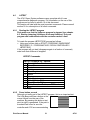
1
A741
Controller
Print Server Manual
RICOH GROUP COMPANIES
Introduction
The A741 Repro System Print Server is a sophisticated option which will turn a RICOH A741
large format printer into a plotter and scanner. Although not a complex device, the A741 Repro
System solution is very versatile.
This document is intended to assist in the installation and configuration of the A741 Repro
system.
It contains a wealth of information and experience. With the information contained in this manual
it will be possible to successfully install the A741 Repro controller and provide first-line support.
Table of Contents
1
SPECIFICATIONS .............................................................................................. 1
1.1 A741 SPECIFICATIONS (BASIC) ..................................................................... 1
1.2 A741 REPRO SPECIFICATIONS ..................................................................... 1
1.2.1
1.2.2
1.2.3
1.3
1.4
1.5
1.6
1.7
2
File Formats................................................................................................................1
Operating System(s)...................................................................................................1
Printer Drivers.............................................................................................................2
A741 REPRO FUNCTIONS (PRINTING) ........................................................... 2
A741 REPRO FUNCTIONS (SCANNING) .......................................................... 2
A741 REPRO FUNCTIONS (MANAGEMENT) .................................................... 2
OPTIONS .................................................................................................... 3
MINIMUM PC SPECIFICATIONS (SERVER ONLY) .............................................. 3
INSTALLATION .................................................................................................. 5
2.1
2.2
2.3
2.4
2.5
2.6
2.7
2.8
EPROM REPLACEMENT .............................................................................. 5
NEW SIMULATIONS ..................................................................................... 5
A741 INTERNAL CABLING ............................................................................. 6
PC SPECIFICATIONS .................................................................................... 6
PCI CARD INSTALLATION .............................................................................. 6
SIZE OF PAGING FILE .................................................................................... 7
PC BIOS SETTING ........................................................................................ 7
A741 REPRO SOFTWARE INSTALLATION........................................................ 8
2.8.1
2.8.2
2.8.3
A741 Repro System Software installation ..................................................................8
How to switch the A741 Repro System to a different language? ...............................9
How do I de-install the A741 Repro System program? ............................................10
2.9 PC NETWORKING ...................................................................................... 11
3
FUNCTIONAL BLOCK DIAGRAM OF A741 REPRO SYSTEM....................... 13
4
TROUBLE-SHOOTING ..................................................................................... 15
4.1
4.2
4.3
4.4
GENERAL.................................................................................................. 15
SIGNS OF PROBLEMS ................................................................................. 15
PROBLEM LISTING...................................................................................... 15
DETAILED CORRECTIVE ACTIONS ................................................................. 16
4.4.1
4.4.2
4.4.3
4.4.4
4.5
4.6
4.7
4.8
4.9
Check the operation of the network..........................................................................16
Make sure the operator of the A741 Repro System has 'Administrator' rights ........16
Select the correct PCI slot for the A741 Repro System card ...................................16
Each time I re-boot the Server PC, rfxServer will not start.......................................17
STARTING (STOPPING) LITTLEBEAR DRIVER AND RFXSERVER ........................ 17
RFXSERVER WILL NOT START ...................................................................... 18
USE OF THE EVENT LOG ............................................................................. 19
CANNOT MAXIMIZE CLIENT WINDOW ............................................................ 19
LBTEST .................................................................................................. 21
4.9.1
Starting the LBTEST program ..................................................................................21
Print Server Manual
i
A741
4.9.2
4.9.3
4.9.4
4.9.5
4.9.6
4.9.7
5
Press button on card ................................................................................................21
Test Selection ...........................................................................................................22
Test command – B(utton) .........................................................................................22
Test command – P(rint) ............................................................................................22
Test command – F(ifo) .............................................................................................22
Re-starting or stopping the Littlebear driver and rfxServer ......................................22
INSTALLING / USING NETWORK CLIENTS ................................................... 23
5.1
5.2
5.3
5.4
5.5
5.6
GENERAL.................................................................................................. 23
A741 REPRO SERVER PREPARATION .......................................................... 23
INSTALLING THE REPRO SYTEM FROM CD-ROM.......................................... 23
INSTALLING THE REMOTE CLIENT SYSTEM ON REMOTE PC’S ......................... 24
MULTIPLE REMOTE CLIENTS....................................................................... 24
VIEW THE STATUS OF A REMOTE A741 PRINTER ........................................... 25
6
DIRECT PRINTING FROM AUTOCAD............................................................. 27
7
A741 REPRO PROGRAM................................................................................. 29
7.1
7.2
7.3
7.4
7.5
7.6
8
INTRODUCTION .......................................................................................... 29
SETTING PROGRAM OPTIONS ...................................................................... 29
SETTING PROGRAM DEFAULTS .................................................................... 30
IMPORTING DOCUMENTS, HOW ARE THEY PROCESSED? ................................ 30
USE OF PENSETS ....................................................................................... 31
USE OF STAMPS ........................................................................................ 31
FREQUENTLY ASKED QUESTIONS: GENERAL ........................................... 33
8.1 WHAT IS THE PURPOSE OF THE XI REPRO SYSTEM PRINT SERVER? ........... 33
8.2 WHAT ARE THE MINIMUM SPECIFICATIONS FOR THE A741 REPRO SYSTEM PRINT
SERVER? .......................................................................................................... 33
8.3 CAN I USE THE A741 PRINT SERVER FOR OTHER JOBS AS WELL?.................. 33
8.4 CAN I USE AN EXISTING PC FROM THE CUSTOMER? ..................................... 33
8.5 WHICH SOFTWARE IS BUNDLED WITH A741 REPRO SYSTEM? ....................... 33
8.6 WHAT IS THE DIFFERENCE BETWEEN PRINTING AND PLOTTING? ..................... 34
8.7 WHAT IS THE DIFFERENCE BETWEEN RASTER AND VECTOR FILES (FORMATS) .. 34
8.8 WHAT IS RASTERISING? ............................................................................. 34
8.9 WHAT IS VECTORISING? ............................................................................. 35
8.10 WHICH VECTORISE PROGRAMS CAN YOU RECOMMEND?................................ 35
8.11 IF I WANT TO SCALE AN IMAGE WHICH FORMAT WILL GIVE THE BEST RESULTS? 35
9
FREQUENTLY ASKED QUESTIONS: A741 REPRO SYSTEM OVERVIEW .. 37
9.1 NETWORK BLOCK DIAGRAM ........................................................................ 37
9.2 WHICH ITEMS ARE INCLUDED IN THE A741 REPRO SYSTEM PC?................... 38
9.3 CAN I USE ANY EXISTING A741 IN COMBINATION WITH THE A741 REPRO
SYSTEM PRINT SERVER? ................................................................................... 38
A741
ii
Print Server Manual
10 FREQUENTLY ASKED QUESTIONS: PRINTING/PLOTTING ........................ 39
10.1 FROM WHICH PROGRAMS CAN I PRINT? ....................................................... 39
10.2 WHICH PRINTER DRIVERS ARE AVAILABLE? .................................................. 39
10.3 CAN WE PRINT GRAYSCALES WITH THE A741 REPRO SYSTEM? ..................... 39
10.4 IF MY PROGRAM/OPERATING SYSTEM DOES NOT SUPPORT THE A741 REPRO
SYSTEM (A741) PRINTER, CAN I STILL PRINT/PLOT? ............................................. 39
10.5 CAN WE PRINT FROM UNIX OR MACINTOSH SYSTEMS? ................................ 39
10.6 CAN WE SUBMIT PRINTJOBS VIA E-MAIL? ...................................................... 39
10.7 WHICH EMULATION'S & FILE FORMATS DO WE SUPPORT? .............................. 39
10.8 WHAT PRINT PROPERTIES CAN I SELECT BEFORE THE DOCUMENT IS PRINTED?40
10.9 CAN WE PRINT MULTIPLE DOCUMENTS? ....................................................... 40
10.10 CAN WE DO GROUP OR SET PRINTING? ..................................................... 41
10.11 CAN WE ADD INFORMATION (TEXT) TO EACH PRINTED DOCUMENT? ............. 41
10.12 WHAT IS A PENSET? ............................................................................... 41
10.13 CAN WE DEFINE CUSTOM PEN SETS? ........................................................ 41
10.14 CAN WE OVERRIDE PENSETS IN A PLOT? ................................................... 41
10.15 CAN WE HANDLE OCE .RCH JOBS? ........................................................ 41
11 FREQUENTLY ASKED QUESTIONS: IMAGE VIEWING/HANDLING............. 43
11.1 CAN WE PREVIEW THE DOCUMENT BEFORE PLOTTING/PRINTING?................... 43
11.2 CAN WE MODIFY THE IMAGE BEFORE IT WILL BE PRINTED? ............................. 43
11.3 WHICH IMAGE HANDLING OPTIONS DOES A741 REPRO HAVE?....................... 43
12 FREQUENTLY ASKED QUESTIONS: NETWORK .......................................... 45
CAN WE PRINT VIA A NETWORK? ................................................................. 45
CAN WE PRINT FROM UNIX OR MACINTOSH SYSTEMS? ................................ 45
WHICH NETWORKS & PROTOCOLS CAN WE USE?.......................................... 45
CAN WE SUBMIT PRINT JOBS VIA E-MAIL? ..................................................... 45
WHAT IS CREATED WHEN THE RICOH CONTROLLER AND A741 ARE INSTALLED
ON A NETWORK? ................................................................................................ 45
12.6 HOW ARE THE A741 PRINT DRIVERS LOADED FOR THE REMOTE CLIENT PC? . 45
12.7 MY, REMOTE NETWORK PC WITH CAD SOFTWARE LOADED CANNOT PRINT TO
THE A741. WHY? .............................................................................................. 46
12.8 HOW ARE LICENSES CONFIGURED FOR THE A741 PRINT SERVER? ................ 46
12.9 WHAT PROTOCOLS ARE COMPATIBLE WITH THE A741 PRINT SERVER? .......... 46
12.10 WHAT MEDIA ACCESS METHODS ARE COMPATIBLE WITH THE A741 PRINT
SERVER? .......................................................................................................... 46
12.11 ARE THERE ANY PASSWORD RECOMMENDATIONS TO BE MADE FOR THE A741
PRINT SERVER AND REMOTE CLIENT PC'S? ........................................................ 46
12.12 HOW IS THE A741 PRINT SERVER INSTALLED IN A STAND-ALONE
CONFIGURATION WITH NO NETWORK? .................................................................. 47
12.1
12.2
12.3
12.4
12.5
13 FREQUENTLY ASKED QUESTIONS: SCANNING ......................................... 49
13.1 CAN WE USE THE A741 FOR SCANNING? ..................................................... 49
13.2 CAN WE SCAN MULTIPLE DOCUMENTS.......................................................... 49
Print Server Manual
iii
A741
13.3 CAN WE EDIT THE SCANNED DOCUMENTS..................................................... 49
13.4 CAN WE REDUCE OR ENLARGE THE SCANNED IMAGE ..................................... 49
13.5 CAN WE SCAN A PART OF AN IMAGE? ........................................................... 49
13.6 CAN WE SCAN GRAY SCALES?..................................................................... 49
13.7 CAN WE SCAN FROM A NETWORK PC? ........................................................ 49
13.8 CAN WE SCAN AT A LOWER RESOLUTION TO REDUCE THE FILESIZE? ............... 50
13.9 WHAT IS DE-SPECKLE? .............................................................................. 50
13.10 WHAT IS DE-SKEW? ................................................................................ 50
14 FREQUENTLY ASKED QUESTIONS: PROJECT MANAGEMENT................. 51
14.1
14.2
14.3
14.4
WHAT IS THE PURPOSE OF A PROJECT?....................................................... 51
HOW MANY GROUPS CAN BE IN A PROJECT?................................................. 51
HOW MANY PROJECTS CAN WE MANAGE WITH A741 REPRO SYSTEM?........... 51
DO WE PROVIDE ANY KIND OF ACCOUNTING? ............................................... 51
15 GLOSSARY ...................................................................................................... 53
16 DESCRIPTION OF LBTEST PROGRAM.......................................................... 61
16.1 PURPOSE OF DOCUMENT .......................................................................... 61
16.2 LBTEST COMMANDS ................................................................................ 61
16.3 COMMAND: “1”......................................................................................... 61
16.4 COMMAND: “2”......................................................................................... 61
16.5 COMMAND: “C”.......................................................................................... 62
16.6 COMMAND: “I” ........................................................................................... 62
16.7 COMMAND: “R”.......................................................................................... 63
16.8 COMMAND: “S” .......................................................................................... 63
16.9 COMMAND: “V” .......................................................................................... 64
16.10 COMMAND: “W” ...................................................................................... 64
16.11 COMMAND: “D”....................................................................................... 64
16.12 COMMAND: “F” ....................................................................................... 65
16.13 COMMAND: “T” ....................................................................................... 65
16.14 COMMAND: “Q”....................................................................................... 66
16.15 TROUBLESHOOTING:............................................................................... 66
A741
iv
Print Server Manual
1 Specifications
1.1
A741 specifications (basic)
Type:
Original format:
Output format:
Resolution:
Printing system:
Grayscales:
Print speed:
Warm-up time:
First copy time:
Zoom range:
Max. copies:
Paper input:
Material type:
Material weight:
Size (W x H x D):
Weight:
1.2
1.2.1
Console
Max. 920 x 5.000 mm
Min. 210 x 297 mm (A4R)
Max. 920 x 5.000 mm
Min. 210 x 297 mm (A4R)
400 dpi * 400 dpi
LED
128 (32 levels/pixel)
4.8 m/min.
10 minutes or less
30 seconds or less (A1)
25% to 400% in 1% or 0.1% increments
20
99 (with MB-1 memory unit)
2 rolls & bypass, 3rd roll optional
Paper, Vellum & Film
80 g/m2
1.521 x 1.388 x 813 mm
314 kg
A741 Repro Specifications
File Formats
The following fileformats and emulation’s are supported by the A741 Repro System
software:
Emulation’s (both vector oriented)
HP-GL & HP-GL/2
CalComp 906/907
Vector Formats
PostScript Level II (future option)
AutoCAD .DRW (future option)
Raster Formats
TIFF 6.0 (B/W only, all compression formats supported)
ATT, MS Bitmap (.BMP), CALS Raster Type I (Type 2 tiled),
Brooktrout FAX, CIF , DIB, GIF, IFF, Gem Raster (IMG), ICA,
JPEG, MacPaint, MS Paint, PBM, Kodak Photo CD, PC Paintbrush,
PGM, Mac Pict, PNG, PNM, PPM, Adobe PhotoShop, Sun Ras,
Targa(TGA),, Windows Metafile, WP graphics metafile, X bitmap,
X Pixmap, X Windows dump.
1.2.2
Operating System(s)
A741 Repro Print Server:
Windows NT 4.0 Workstation (with SP 3)
Windows NT 4.0 Server
Client PC’s:
Windows NT 4.0
Print Server Manual
1
A741
1.2.3
Printer Drivers
Printer drivers:
Windows NT 4.0
AutoCAD ADI, version 12*, 13* & 14*
1.3
A741 Repro functions (Printing)
Resolution:
Gray scales:
Media selection:
Cut length:
Scaling:
Rotation:
Image manipulation:
Margins:
1.4
400 dpi * 400 dpi
2 (Black/White only)
By Roll (max. 3 + bypass), by Type (Paper,
Vellum or Film) or Roll Width.
Image length or user definable length
25% to 400%
0°, 90°, 180°, 270°
Invert, Mirror, de-speckle
Leading + Training edge (max: 90cm)
Pensets:
As defined in plot file or user defined Pensets
(max. 255 pens)
Stamps:
Multiple text stamps
User definable text, font, rotation, and free
positioning inside or outside of image.
11 Pre-defined parameter macro’s like date/time
of printing, filename etc.
Image editing:
De-speckle, De-Skew, Invert, Mirror, Scale,
Rotate
Image viewer:
Wang Imaging (standard utility of
Windows NT)
Project management:
Unlimited projects. Per project plots can be
organised into (multiple) sub-projects. Pensets
and stamps can be assigned to the whole
project, to a sub-project and to plots individually.
A741 Repro functions (Scanning)
Resolution:
400 dpi * 400 dpi
Gray scales:
2 (Black/White only)
File naming:
Manual or Automatic
Continuous (batch) scanning: Yes (up to 999 scans per batch)
File format:
TIFF (Group IV compressed)
Image control:
Image density setting
Scaling:
25% to 400%
Area selection:
Automatic, by Width/Length or standard paper
sizes
1.5
A741 Repro functions (Management)
User definable help text:
Report generation:
Report types:
Selection criteria:
Database format:
A741
Yes
Yes, simple text file output
3: Summary, detail and full listing
By User ID, Cost Center, Plotter ID and
Date/Time range
MS-Access
2
Print Server Manual
1.6
Options
PostScript Level II module*
Direct printing of AutoCAD .DWG files*
Print manager for Client stations*
1.7
Minimum PC specifications (Server only)
Processor:
Memory:
Harddisk:
Monitor:
Software:
Network interface:
Pentium Pro or Pentium II 200Mhz or faster
128Mb minimum (will not work with less memory!)
2Gb, IDE interface. Actual storage space depends on storage
requirements from the customer.
17" or larger (minimum resolution 800x600)
Windows NT 4.0 workstation (With SP 3)
Any type
* Not fully implemented / to be confirmed
Print Server Manual
3
A741
A741
4
Print Server Manual
2 Installation
2.1
EPROM replacement
In the event of an EPROM change the following procedure will enable the
technician to replace the prom and bring the A741 unit back on line.
The following (minimum) procedure should be followed after replacing the
EPROM, failing to do so may result in some unpredictable behavior.
• Run SIM 66 and write down the developer initial value
• Run SIM 70 (backup RAM initialization) and wait for the OK message
• Run SIM 81 to re-set the display language from Japanese to the desired
language.
• Run SIM 66 again, re-entering the value recorded above
• Re-enter all factory default values as found on the large label on the inside
of the left cover or on the rear panel.
• Clean the contact glass and rollers and perform SIM 120 (γ auto adjust)
• Press the clear key and all clear key, select SIM 001 and return to the
normal operation mode. Switch the A741 off and on again.
2.2
New SIMulations
Several new SIMulations are used to control the A741 Repro System, the 2
most important are discussed below:
SIM 115
Set to '2: UNIT ON', this will enable the interface, if set to '1: UNIT OFF'
the server PC will not detect the A741. Default setting after changing the
EPROM’s is off.
SIM 117
Leading edge adjustment for scanning via A741 Repro System.
How to check: Scan an image and print this again at 100%,. See if the
distance from the top of the paper to the top of the image is the same on
the original and the copy, if not change the value of SIM 117.
Print Server Manual
5
A741
2.3
A741 internal cabling
Mount the internal cable and brackets as per A741 Repro System
installation guide (provided separately).
Bracket to
order
2.4
PC Specifications
Please make sure that the Server PC meets the following (minimum)
specifications
♦ Pentium PRO / Pentium II 200Mhz or faster
♦ 128Mb of internal memory
2.5
PCI card installation
Remove the power cable from the PC.
Open the PC housing.
Install the A741 Repro Card into a free PCI slot.
Quick test:
• Connect the A741 signal cable to the controller.
• Switch-on the PC and A741 and wait until the A741 is ready.
• Make sure the A741 is on-line.
• Press the small button at the corner of the PCI card. This should give a
test print as seen below:
Note:
For a more detailed test procedure see chapter: 4.9, LBTEST
See also correct positioning of the PCI card, chapter: 4.4.3, Select
the correct
PCI slot for the A741 Repro System card
A741
6
Print Server Manual
2.6
Size of paging file
Windows can simulate more memory than physically available in the
machine. The additional memory is simulated by means of a paging file on
the harddisk. Please make sure that the size of this paging file is set
correctly, minimum 300Mb, maximum size 500Mb.
How to set/check?
Goto the 'control panel' and start the 'System' applet, select the
'Performance' tab and set/check the minimum and maximum values.
2.7
PC bios setting
Unlike Windows '95, Windows NT 4.0 is not a plug-and-play operating
system. To avoid potential problems with the setup of the PCI cards, we
have to set the PC bios not to expect a PnP operating system. The bios will
then take care of the Interrupt and DMA assignments.
How to set/check?
NOTE: This procedure will work on many Mainboards, systems like DELL, Compaq etc.
have their own way of entering the BIOS setup and BIOS settings. Some systems do not
offer this setting or it is located at a different location as described below.
• At power-up selftest hit the DEL key.
• Look for the PCI/PNP settings
• Check if there is a setting like 'PnP aware OS' or 'PnP enabled OS',
change this setting to 'No' or 'Disabled'.
Print Server Manual
7
A741
Also make sure that the Power saving option is disabled as well. If the
power saving is enabled you may encounter all kind of network printiing
problems.
2.8
2.8.1
A741 Repro Software installation
A741 Repro System Software installation
Installation of the A741 Repro System software is very easy, just insert the
CD and it will auto run the set up routine on the distribution CD-ROM.
Depending on the type of installation the behavior of the installation
program may be slightly different (typically installing the client or server
software or installing a new version of the software).
Upgrading an existing installation
• In the list with options, various items are de-selected. Do not alter this list,
otherwise you overwrite information which must be saved between
updates (accounting information etc.)
Various hints & Tips on installation
User rights
During installation (and also normal operation!) of the A741 Repro Software
on the Server PC, the currently logged-in user must have administrator
rights. Either log-in as the administrator or ask the administrator to assign
the 'Administrator' rights to your account.
Device selection
• Select the current device name for your region (8020 is for Europe, 3648
is for USA and 630 is for the Japanese market)
• Select 'Client Software Only' on Windows NT systems which will print via
the network.
A741
8
Print Server Manual
• When re-installing (updating) the A741 Repro Software occasionally the
next warning my appear:
Just click Yes and ignore the message.
• After the installation of A741 Repro System software the PC must be rebooted before all settings/actions will take effect.
2.8.2
How to switch the A741 Repro System to a different language?
Normally the A741 Repro System software will adapt to the native language
of the Windows software. The current available languages are: English,
German, French, Italian, Spanish and Dutch. For any language not
listed,English will be selected.
It is however possible to run the A741 Repro software in a different
language.
• Stop the Client program
• In the control panel, double-click on the 'Regional Settings' applet.
• Change the language setting to one of the languages as mentioned above
• Re-start the Client program
NOTE:
Changing the language in this way also has an effect on the way numbers,
currencies and date/time are displayed. Part of the dialog texts are formed by
Windows, so occasionally a mix of both languages will be displayed.
Print Server Manual
9
A741
2.8.3
How do I de-install the A741 Repro System program?
Either to remove the A741 Repro software from the computer or if instructed
to do so in case of a software update it may be necessary to de-install
(remove) the software.
In the control panel start the 'Add/Remove software' applet.
• Make sure that the Littlebear driver and Server program are stopped. See
chapter: 4.5, Starting (stopping) Littlebear driver and rfxServer
• Select the Install/Uninstall tab
• Select The 'A741 Repro System' from the list
• Hit the Add/Remove button
A741
10
Print Server Manual
2.9
PC networking
In order for the A741 Repro System to work properly, there must be an
active network environment, even for a stand-alone A741 Repro Server.
Use the procedure below if the A741 Repro print server is not connected to
-and participating in- an active network.
Without a previous network installation (or a system without a network card)
• Open the 'Control Panel -/Network' /Adapters /Add
• Choose the 'MS Loopback' adapter from the list and click OK. Depending
on uyour specific installation the Windows NT system disk may be
needed.
• Select the 'Protocols' tab
• Choose the NetBEUI protocol and press 'Enter' on the packet size
question. If NetBEUI is not listed go back to Add and select it from the
list and click OK.
• Close the Network routine and re-start the PC.
• To check if the network is functional by double-clicking on 'Network
Neighborhood' to see if your PC name is listed (note: this may take
several minutes)
Print Server Manual
11
A741
With a previous network installation
NOTE:
This procedure is only required when the PC is used stand-alone for
demonstration purposes etc.
• Install the 'MS Loopback' adapter as above,
• Select the 'Bindings' tab,
•
From the 'Show bindings for' drop-down box select 'all adapters',
Note: Both the network adapter(s) and the MS Loopback should be listed,
•
Highlight the network adapter(s) and press the 'Disable' button
Note: Make sure the MS Loopback adapter remains enabled!
• Close the network applet and re-start the PC
• Verify the network operation by double-clicking 'Network Neighborhood'.
HINT: When returning the PC to an active network environment disable the
MS Loopback adapter and re-enable the network adapter(s)!
A741
12
Print Server Manual
3 Functional block diagram of A741 Repro System
Local Client
Remote Client(s)
C
Local
Spool
E
rfxServer
D
Remote
Spool
A
Littlebear.sys driver
B
Littlebear card
Print Server PC
Explanation of various signals
A. Communication between rfxServer, Littlebear.sys driver and Littlebear card.
Due to the nature of the Windows NT system it is not allowed that programs communicate
directly with hardware. Normally this communication is done via a driver. The rfxServer
program can now communicate in a hardware independent way. To control a different printer
only the card and driver software need to be replaced.
B. Communication between driver and card.
C. Network communication
The Server and Client programs exchange (status)information via 'named pipes' through the
network. If a Client detects that rfxServer is present on the same system, it will be given the
status of 'Local Client', if the server is not present or not started, the Client will assume the
role of 'remote client'. This is the main reason why there must be an active network, even on
a stand-alone system.
Print Server Manual
13
A741
D. Flow of print jobs
Both Local- and remote Clients can generate print jobs. These jobs are stored in the ‘Local
Spool’ directory for the local client and in the ‘Network Spool’ directory for network clients.
RfxServer will constantly monitor one of these two directories, based on the ‘Mode’ setting of
the Local client.
E. Scanning
Scanning is done directly by the local client. At scan time, the local Client will take-over the
control of the system from rfxServer. Due to this method of communication and the need for
interaction between the PC and A741, scanning is limited to the Local Client only.
A741
14
Print Server Manual
4 Trouble-shooting
4.1
General
No two problems are the same, however for frequently appearing problems
this document will contain information how to correct or find the source of
the problem.
General procedure to follow:
• Analyze the type of problem, is it related to the operation of the program,
a program crash or problems with the communication with the A741.
• From this analysis determine the best way to resolve the problem.
Communication problems can best be checked by using the LBTEST
program (see chapter: 4.9)
• The manual for this program (M_LBTEST.TXT) in the A741 Repro
System contains full information how to operate this program and a
comprehensive diagnostic procedure.
4.2
Signs of problems
This section focuses on the Server PC only, problems with network clients
are mainly related to network connections or incorrect use of the client
program.
A main sign of problems is the absence of the scan button when the Client
program is started on the Server PC.
In this case check the operation of the network and try to restart the Server
program (see chapter 4.4, Detailed corrective actions
Check the operation of the network and 4.5, Starting (stopping) Littlebear
driver and rfxServer)
Another major problem is the printing of white pages, or pages with a few
centimeters of information followed by lines in the length of the page.
Please see chapter 4.4.3, Select the correct PCI slot for the A741 Repro
System card for a possible fix of the problem.
4.3
Problem listing
The Scan button is missing on the Local client
• Check the operation of the network, see chapter 4.4.1, Check the
operation of the network
• See if the rfxServer is started, chapter 4.5, Starting (stopping)
Littlebear driver and rfxServer
The Client program crashes when importing a document or when
printing
• Check the size of the paging file, see chapter 2.6, Size of paging file
Print Server Manual
15
A741
•
See chapter 4.4.2, Make sure the operator of the A741 Repro System
has 'Administrator' rights
The A741 produces blank pages when printing
• Re-install the LittleBear card in a different PCI slot, see chapter 4.4.3,
Select the correct PCI slot for the A741 Repro System card
Only a part of the Client window is shown, impossible to re-size to full
view
• Check fontsize setting of display. See chapter 4.8 Cannot maximize
Client window
The Server program does not start (at Boot time or when started
manually from the Control panel)
• See if the Littebear driver is started, see chapter 4.5, Starting
(stopping) Littlebear driver and rfxServer
See also chapter, 4.6 rfxServer will not start
4.4
4.4.1
Detailed corrective actions
Check the operation of the network
Server PC
Check if the network is operational, do this by double-clicking on the
'Network Neighborhood' icon. If you are connected to an existing network
you must see a list of computers in the network. If you run the Server PC
stand-alone you must see just one PC (the Server PC!). If not, check the
network setup of the PC, for a stand-alone Server PC see chapter: 2.9,
PC networking
Client PC
Make sure the Server PC is working and configured properly (including the
network connection).
Double-click on the 'Network Neighborhood' icon of the Client PC and see
if the Server PC is present, if not find-out why and correct the problem.
4.4.2 Make sure the operator of the A741 Repro System has
'Administrator' rights
The 'Administrator' rights are required on the Server PC only, not on the
Client PC's. Typical sign of this problem is an error message that the path
of the 'LOCAL SPOOL' directory cannot be found in the REGISTRY.
4.4.3 Select the correct PCI slot for the A741 Repro System card
It is known that the A741 Repro System PCI controller may not work
properly with all motherboards. Signs of trouble are problems with DMA
transfers (see chapter: 4.9.6, Test command – F(ifo) ).
Until now this problem has only been seen on Pentium II systems, but may
be present with other type of processors as well.
Which boards will work correctly?
• Systems with original Intel AL440LX Pentium II motherboards,
A typical board with problems is shown on the next page:
A741
16
Print Server Manual
This slot gives
problems
This slot works
fine
QDI Legend V, Pentium II
motherboard
4.4.4
Each time I re-boot the Server PC, rfxServer will not start
If this problem occurs immediately at boot time, delete all files in the
'X:\Program Files\A741 Repro System\Local Spool' directory. Here the
Local Client program will store print jobs. At startup time, the server looks in
this directory for print jobs. If it find a job it will immediately start processing
this job. If this job contains a problem of some sort, the server might crash
or produce wrong output immediately at startup time. To fix this problem
delete all files in the 'Local Spool' directory before re-booting the system.
If the problem occurs when the Server PC is switched to the Network
printing mode, delete the (problem) file(s) in the 'Network Spool' directory.
4.5
Starting (stopping) Littlebear driver and rfxServer
Normally the Littlebear device driver and Server program are started
automatically when the Server PC is (re)booted. It may however be
necessary to start or stop one of these components manually.
To start or stop one of the components use:
Littebear driver: 'Control panel -> Devices'
rfxServer:
'Control panel -> Services'
Print Server Manual
17
A741
4.6
A741
rfxServer will not start
Due to an error of some kind it is possible that rfxServer will not start. In this
case, the Services applet will show an error message approx. 10-15
seconds after the rfxServer is started.
To find the reason why the rfxServer will not start, you can select one of the
3 options below:
See if the Littlebear driver is started (is a A741 Repro PCI card installed in
the system??) (see chapter 4.5, Starting (stopping) Littlebear driver and
rfxServer)
• Look in the event log file for a possible reason (see chapter: 4.7, Use of
the Event log)
• Start the rfxServer from in a DOS box
♦ Open the 'Program Files\A741 Repro System' directory
♦ Create a shortcut to rfxServer
♦ Select the properties of this shortcut
♦ Add the command switch '–C 7' to the command line (after the
closing double-quote!)
♦ Close and then double-click on the shortcut to start rfxServer in a
DOS box.
Note: rfxServer will produce a lot of internal messages, some which
may look like errors. Only start rfxServer in this way if there are real
problems or if instructed to do so.
18
Print Server Manual
4.7
4.8
Use of the Event log
The event log is a useful source to analyze problems. If rfxServer stops due
to a problem, in many cases it will leave a message in the event log. A real
crash of course will not leave an event message.
How to see this event log:
Make sure you have administrator rights (or login as the Administrator)
Press the start button, and select 'Administrative Tools (common) -> Event
viewer'
In the LOG menu there are 2 important options: System and Application.
Both can be inspected for signs of trouble.
The example below shows an Application event log, by double-clicking on
an event more details are shown. In this case it is a message that there is
no controller present.
Cannot maximize Client window
In some cases only a part of the
Client window is shown and it is
not possible to maximize the
window to full size.
This problem is caused by the
setting of the fontsize in the
Display properties. Change the
‘Large Font’ setting to ‘Small
font’ setting. After this change
the full windows will be shown
again. See picture below for
incorrect window size.
Print Server Manual
19
A741
A741
20
Print Server Manual
4.9
LBTEST
The A741 Repro System software comes complete with it's own
comprehensive diagnostic program. Full information on the use of this
program can be found in section 16 ot this document.
This section will deal with the most important commands. Please consult
section 16 for a description of all other commands.
4.9.1
Starting the LBTEST program
First make sure that the rfxServer program is stopped (see chapter
4.5, Starting (stopping) Littlebear driver and rfxServer). Only one
program can communicate with the controller card at a time.
To locate the program LBTEST.EXE proceed as follows:
• Using your mouse click on START / PROGRAM / WINDOWSNT
EXPLORER / C: / PROGRAM FILES / RICOH CONTROLLER /
LBTEST.EXE
If the program will not start (disappears again in a fraction of a second)
make sure that rfxServer is stopped!
LBTEST Commands
LBTEST VERSION x.x, Options:
1 Reset LittleBear Device
2 Clear Fifos
c Control
i Initialize
r Read Register
s Status
v Version
w Write Register
d Write Fifos Via DMA
f Read Fifos Via DMA
t Print, Scan, test Button, or FIFO tests
q Quit
4.9.2
Press button on card
Although not really part of the LBTEST program, this is an important test.
The Little Bear card has a button on the
corner futhest from the rear of the
machine. By pressing this button a test
print (at right) is generated. If the print is
successful we know for sure the
controller and A741 are communicating
Print Server Manual
21
A741
properly. Please make sure the A741 is on-line, since there will be no
feedback by this test. The test pattern is fully generated by the controller
card and can be issued at all times, even if the A741 Repro System
software is not installed.
4.9.3
Test Selection
Inorder to perform the following procedures it only necessary to select the "t" from the
LBTEST command list aove. This is where the following tests are located.
4.9.4
Test command – B(utton)
Select "B" from the commands listed
under "t". Same test as pressing the
button on the Little Bear card above.
This time the command is given by
software with minimal interaction with
the controller card. Again, the test print
is generated by the controller.
4.9.5
Test command – P(rint)
Select "P" from the commands listed
under "t". A more comprehensive test.
The LBTEST program will generate a
checker-board test pattern simulating
the normal data transfer. If this test
works o.k., then basically the PC and
the PCI card are working fine.
4.9.6
Test command – F(ifo)
Select "F" from the commands listed under "t". This test is mainly used to
test the communication between the software and controller hardware. If
there are any PCI bus problems this test will fail. (see chapter 4.4.3, Select
the correct PCI slot for the A741 Repro System card)
4.9.7
Re-starting or stopping the Littlebear driver and rfxServer
First make sure that the rfxServer program is stopped (see chapter 4.5,
Starting (stopping) Littlebear driver and rfxServer). Folow the same
procedure used for stopping the littleBear driver to restart the system. If the
system will not restart (see chapter 4.5, Starting (stopping) Littlebear driver
and rfxServer). or simply shut the system down and restart.
A741
22
Print Server Manual
5 Installing / Using Network Clients
5.1
General
With version 2.2.9 of A741 Repro you now can run the Client software on
Window NT. This section will describe the installation and use of network clients.
5.2
5.3
A741 Repro Server preparation
On the A741 Repro Server PC make sure the remote users have access to
the shared resources (printers, folders etc.). There are 2 possible methods
to do this:
• Enable the Guest account
Use the ‘Start menu->Programs->Administrator tools->User manager’ to
enable the guest account. Enabling this account will allow all users in
the network to see and access shared resources. To limit access to
individual users / groups, use the next method.
• Create new user entries
If you want to limit access to specified persons only, create an user
account for that specific user and disable the Guest account.
Use the ‘Start menu->Programs->Administrator tools->User Manager.User->New User’ to create new users entries
Installing the Repro Sytem from CD-ROM
The supplied CD-ROM contains:
• Xi Repro System (the program for plotter controller)
• LittleBear Driver (the driver which communicates between copier and
interface card)
• Installer (program to install Xi Repro System and the LittleBear Driver)
Use the procedure below to install the printer driver on Windows NT and
clients:
Installing Xi Repro Server/ Local Client system System
• Start Windows NT and close any unnecessary applications.
• Insert the supplied CD-ROM into the CD-ROM drive.
• The Setup screen appears followed by the Welcome screen. Click on the
“Next” button.
• The Choose Destination Location screen appears. Click on the “Next”
button.
• The Setup Type screen appears. Select “Type 7030D” to install Xi Repro
System on a Server/ Local Client system and click on the “Next” button.
Print Server Manual
23
A741
• The Select Components screen appears. When setting up the Server/
Local Client system select all the components listed and click on the
“Next” button.
• The Select Program Folder screen appears. Click on the “Next” button.
• The program group name can be changed to any desired name.
• The Start Copying Files screen appears. Click on the “Next” button.
• The Setup Complete screen appears after installation is completed.
Remove the CD-ROM from the CD-ROM drive and click on the “Finish”
button to restart the computer automatically.
• Proceed to Setting the copier.
The installation program creates a program item in the Start menu. The
program group name is “Xi Repro System”, which contains three program
items called Client, Admin and Stamp. The plotter driver is installed in the
Windows NT Printers folder at the same time.
When uninstalling Xi Repro System, files in the C:\Program Files\Xi Repro
System\Plots directory may be deleted. Move any image files before
uninstalling Xi Repro System.
5.4
5.5
Installing the Remote Client system on remote PC’s
Insert the A741 Repro CD-Rom or start the set-up program via the network.
Follow the installation procedure as shown aboveexcept for the following
two steps:
• The Setup Type screen appears. Select “Client Software” to install Xi
Repro System on a Remote Client system and click on the “Next” button.
• The Select Components screen appears. When setting up the Remote
Client system "do not select Server" select all the three remaining
components and click on the “Next” button.
• All other steps remain the same.
Multiple Remote Clients
Muultiple A741 Repro Servers (printer) can reside on a single network. In a
network network environment each A741 Repro Servers (printer) can be
individually identified as can each Remote Client PC. This will enable each
Remote Client PC to address and print on any number of A741 Repro
Servers (printer). At print time the user can easily select the desired printer
from the dialog box like that shown:
A741
24
Print Server Manual
In the printers drop-down box all A741 systems in the network will be shown
and can be selected at this point.
5.6
View the status of a remote A741 printer
Select the ‘View->Network
System Status’ menu. This will
show the dialog box at right:
In this dialog box it will be
possible to select and see the
status of any A741 connected to
the network.
Print Server Manual
25
A741
A741
26
Print Server Manual
6 Direct printing from AutoCAD
With version 1.5x of the A741 Repro software it will be possible to print directly from AutoCAD to
a A741 printer. Please use the setup procedure below to do the right set-up.
•
•
•
•
Start AutoCAD (or AutoCAD Lite)
Select the File->printer Setup menu
For an existing printer select Modify->Reconfiguration.
To add a new printer select ‘Add’, from the list of available manufacturers select the Hewlett
Packard HP-GL/2 drivers
• Then select the HP DesignJet 650C
• Connect the plotter to a Network connection. From the browse window shown, select the
desired A741 Repro Server and then the (shared) A741 printer.
Normally this would end the printer setup. However some additional changes can be made,
suggestions to change:
• Write to plot file: NO
• Size units: Millimeters
• Maximum paper size: A1
• Remove hidden lines: Yes
The user can now use the normal File->Print option to print the AutoCAD file.
HINT: make sure the A741 Repro is in the network mode, if not the plots are stored in the
‘Network Spool’ directory and will not print until the A741 Repro is switched to network mode.
From AutoCAD the user can select the desired output size. The A741 Repro will automatically
use the roll of paper best suited for the job. If you want to have specific control of roll selection,
image rotation etc. then print to file and manually import the drawing in the Client window and
print from here.
HINT: For direct printing from AutoCAD on Client stations it is not necessary to have the Client
software installed or running on that client station.
Sometimes printing from AutoCAD will not show the full drawing. This is no problem from A741
Repro, but is a setting from AutoCAD. After selecting the ‘File->Print’ menu, make sure the
‘Extents’ option is selected in the Additional Properties (see below). Also make sure the AutoCad
drawing is in paper space before printing.
Print Server Manual
27
A741
A741
28
Print Server Manual
7 A741 Repro Program
7.1
Introduction
The A741 Repro Software is not difficult to use. There are however a few
points which need some additional clarification. For a full description of the
program please consult the A741 Repro System Users manual.
7.2
Setting program options
The user can determine the behavior of the program by changing various
optional settings. The picture below shows the most important of these
settings.
➊
➌
➋
➍
➎
1. Units of measurements
Set to desired units of measurement. This will effect the units of
measurement as shown by the A741 Repro program.
2. Use of pensets
Marking this option will use the pen information as defined in the HP-GL
or CalComp file. If marked optional pensets as defined in the project
window have no effect! To use custom pensets, disable this option. This
Print Server Manual
29
A741
option will effect on all documents in the project. It is not possible to
enable/disable custom pensets on a plot by plot basis.
3. Moment of document RIPping (Raster Image Processor, see Glossary)
Typically select the 'RIP immediately' option on the server PC, on all
other network clients set to 'RIP when printed'.
4. Optional settings for server use
These settings have effect on the server PC only. If the 'Prompt on
interrupt' option is enabled you are asked if you really want to interrupt
the current printjob, if disabled the job is interrupted without any
question.
If you do not wish to use the accounting system you can mark the
second item. Normally the accounting system will be used.
5. Image Editor (optional)
By default the A741 Repro Client program will use Imaging for document
viewing. Imaging is a standard accessory program supplied with
Windows '95/NT. Use the Browse button to select any other editor
program if desired.
7.3
Setting program defaults
None of the supported fileformats (TIFF, HP-GL, CalComp etc) will contain
device specific commands like paper/roll selection etc. When importing a
document in a project the default settings are applied for that document.
With the dialog as presented when selecting the 'Tools -> Default Settings'
menu option, you can set these defaults.
7.4
Importing documents, how are they processed?
It is important to understand which processes take place when importing a
file and what happens when rfxServer applies the final settings.
Importing a document.
When importing a document the following processes (actions) will take
place:
Vector files (HP-GL, CalComp) are converted into a bitmap at the original
size (e.g. if the plotdata specifies a A3 size document a true--A3- size
bitmap is generated. During this conversion phase the pen settings are
applied as well (either as specified in the document or defined in the user
pensets).
Bitmap files (BMP, TIFF etc) are decompressed (if necessary) into a truesize bitmap file.
From this true-size bitmap a 'Thumbnail' file is generated for quick and
easy viewing in the client window. Then the true-size bitmap file is
compressed (TIFF G4 compression) and stored as a Raster file. This will
be the actual image which will be printed.
To see where these files are stored goto the plot/print file properties, and
select the names tab.
A741
30
Print Server Manual
Final processing by rfxServer.
When the print command is issued in the server a job file is created and
stored in one of the spool directories. This job file contains both the print
options and the raster file generated in the process above.
The rfxServer will do the following actions:
Decompres the Raster file
Scale and/or rotate the image
Add any stamp
7.5
Use of pensets
Various CAD packages and printers use different pensets, which may or
may not have to be redefined for various software and printers.
As described previously when importing a document, pensets are applied
as the document is RIPped. If a penset is added to a project (by group or
individual files), then initially these settings will have no effect until the file is
re-RIPped again. To do so goto the print/plot file properties and select the
Names tab. Press the RIP button. At this moment only the RASTer file is regenerated. Any changes will not show-up in the thumbnail file. To check if
settings took place start Imaging and see the results.
We now have to add a penset to a project, edit the penset and save it under
a new name. We have to delete the penset we initially added and then
include the newly created penset.
7.6
Use of stamps
Currently we can only use the exiting sample stamps or new stamps
created using only text.
Print Server Manual
31
A741
A741
32
Print Server Manual
8 Frequently Asked Questions: General
8.1
What is the purpose of the Xi REPRO System Print Server?
The A741 Repro System Print Server forms an integral part of the A741.
It serves 4 main purposes:
• Physical connection to the A741 and network (see also 9.2)
• Handle print requests from the -network based- 'clients' (see also 12.2)
• User terminal for scanning actions (see also 13.1-13.6)
• Provide A741 status feedback to the users in the network.
•
8.2
What are the minimum specifications for the A741 Repro System
Print Server?
Minimum specifications are:
Processor:
Pentium Pro or Pentium II 200Mhz or faster
Memory:
128Mb minimum (will not work with less memory!)
Harddisk:
2Gb, IDE interface. Actual storage space depends on
storage
requirements from the customer
Monitor:
17" or larger (minimum resolution 800x600)
Software:
Windows NT 4.0 workstation (With SP 3)
Network interface Any type
8.3
Can I use the A741 Print Server for other jobs as well?
You can use the A741 Repro System server for other jobs as well, but printing
(specifically the RIPping part) demands a lot of resources of the PC. When
sending frequent print jobs to the server, it is advised not to use the server PC for
other tasks.
8.4
Can I use an existing PC from the customer?
Yes, as long as the PC complies with the specifications as mentioned in question
8.2.
Note: It is advised NOT to use the network file server for the A741 Repro
System. In many cases this system will comply to the required specifications.
During printing the A741 Repro System Software requires nearly 100% of the
CPU time and large amounts of memory, disrupting the normal operation of the
file server. (see also 8.3)
8.5
Which software is bundled with A741 Repro System?
With the A741 Repro System program no specific programs for image editing
and manipulation will be bundled. In many cases the user is already using a
variety of image editing/creation programs. Both Windows '95 and Windows NT
have the 'Wang Imaging' program included, standard.
Print Server Manual
33
A741
8.6
What is the difference between printing and plotting?
Currently there is no difference. In the past 'printing' referred to producing text on
paper using a line or matrix printer. 'Plotting' referred to a procedure where a
graphic image (lines, circles etc.) was drawn by moving a pen on a sheet of
paper.
In the case of the A741 we will create the 'plot' image in the memory of the Print
Server, after which we will 'print' the final image.
8.7
What is the difference between raster and vector files (formats)
There are basically 2 ways to store a graphic image in a file:
Raster
The raster image is also referred to as a bitmap image. Basically it can be
described as a matrix of individual black and white dots (or pixels) forming
the image. There are a large number of file formats to describe a raster.
Raster images tend to be very large (a full A0 sheet at 400 dpi will be 32Mb
in size), but can be compressed to a much smaller size. Depending on the
image complexity, compression ranges of 40:1 are possible. Typically a
compressed 36x48 bitmap will be in the range of 1.5Mb to 5Mb.
Example of some raster formats: TIFF, BMP, PCX, HP-RTL (see also
8.8,10.7)
Vector
Vector images typically contain instructions about how to create an image. In
fact the file contains a global description of the 'page' (size, orientation etc.)
and a list of pen movements (e.g. move the pen to location X, draw a line to
location Y etc.)
Even for complex pages the files are relatively small and in general no
compression is used.
Example of some vector formats: HP-GL/2, CalComp (see also 8.9, 10.7)
8.8
What is rasterising?
The final image which will be sent to the printer is always a raster (or bitmap)
image.
Vector format data (like HP-GL, CalComp etc.) must first be converted to this
final raster format. In fact, the image is created inside the memory of the
computer.
Raster images (like TIFF, .BMP, .JPG etc) need to be de-compressed (if
necessary) and adjusted to the resolution of the output device (for the A741
400dpi).
The processes described above are normally referred to as rasterising. (see also
8.7)
A741
34
Print Server Manual
8.9
What is vectorising?
Vectorising is the opposite of rasterising. Vectorising is typically an action done
after a scan. Scanning will result in a raster (bitmap) image, in fact a collection of
individual black and white dots (pixels). A vectorising program will analyze this
image and convert this image back to individual lines -or vectors-. Hence the
name vectorising. (see also 8.7, 11.2)
8.10
Which vectorise programs can you recommend?
AutoCAD version 14 does not have a built-in vectorise option. For AutoCAD rev
13, rev 14 and AutoCAD Lite a vectorise program RxAutoImage Pro LT is
available from Rasterex. For more information on this product please consult the
web page www.rasterex.com.
Additional vectorise (ScanVEC®) and bitmap editing programs are available from
ScanGraphics, Inc. recently changed Name to SEDONA Corporation. See web
page www.sedonacorp.com for more details.
For PostScript solutions you can use Adobe Streamline to vectorise the drawing.
Streamline will produce an Adobe Illustrator vector file. With this latter program
you can easily modify the drawing. For more information see the Adobe web site
at www.adobe.com. (see also 8.7, 8.9, 11.2)
Note: Streamline has limits to the size of bitmaps it can handle and is therefore
not suitable for large engineering drawings (scans).
8.11
If I want to scale an image which format will give the best results?
Scaling a vector image will always give the best results. A vector file contains
drawing instructions. Each time we re-scale the image, a new high quality output
drawing is generated.
Scaling a raster image is a matter of compromise. If we reduce the image it will
look sharper, but finer details may get lost. If we enlarge the image we simply
make it bigger without creating a better quality image. We tend to think that
enlarged images are low in quality, but that is not true. The individual pixels are
simply enlarged, more clearly showing the quality of the original file. (see also
8.7)
Example:
The image on the left is at it's original size, the image to the right is scaled to
400%, it looks lower in quality, but that's not true. The image is simply 4 x larger.
Print Server Manual
35
A741
A741
36
Print Server Manual
9 Frequently Asked Questions: A741 Repro System overview
9.1
Network block diagram
Windows '95
Windows NT
Remote Client
UNIX (any)
Macintosh
Xi REPRO Print Server
- Server (controls A741)
- Local client
- Scanning enabled
From all computers we can print directly to the spool queue on the A741 Repro
System Print Server. The job is then printed based on the defaults as set by the
Local Client program. A client program running on the Print Server is referred to
as the Local Client and has some additional features enabled, such as scanning.
In order to fully control the print job (specify scaling, paper size, rotation etc.) the
job must first be printed to file on a computer. The print file must then be
imported into a Client propram after which the job details can be specified. The
print job is then submitted to the A741 Repro System server after which it is
printed.
The Client program is available only for the Windows NT environment, not for the
Macintosh or UNIX systems. (see also 12.1, 12.2)
Print Server Manual
37
A741
9.2
Which items are included in the A741 Repro System PC?
The following items are contained in the basic A741 Repro System.).
A fully configured PC (chapter 8.2) is required as well as:
•
•
•
PCI interface card
This card provides the physical interface between the PC and the A741. It
uses a proprietary interface with both parallel and serial data signals for
the communication. Only this interface can be used to communicate with
the A741.
A741 Repro System software
A CD-ROM containing all the required drivers, the server and client
programs, tools and diagnostics.
Cables
A set of cables to connect the A741 to the Print Server PC.
9.3
Can I use any existing A741 in combination with the A741 Repro
System Print Server?
Yes, any existing A741 can be used. The only consideration might be that the
EPROM level must be checked to ensure proper installation and operation of the
A741 Repro System.
A741
38
Print Server Manual
10 Frequently Asked Questions: Printing/Plotting
10.1
From which programs can I print?
Basically the user can print from any program (e.g. AutoCAD, Medusa,
Architrion) or operating system (Windows, MacOS, UNIX) which can generate a
document format which is supported by the Print Server.
The most commonly used format is HP-GL/2 (see also 10.7)
10.2
Which printer drivers are available?
Printer drivers will be available for:
Windows NT, Windows '95* and ADI drivers for AutoCAD version 12 *, 13* and
14*
10.3
Can we print grayscales with the A741 Repro system?
No, printing and scanning are limited to 2 grayscales (black & white) only. The
use of gray scales is limited to copying only.
10.4
If my program/operating system does not support the A741 Repro
System (A741) printer, can I still print/plot?
If available select the HP DesignJet 650C, print to file and import this file into the
Client program. The HP DesignJet 650C this is the most universal HP-GL/2
plotter emulation. (see also 10.1)
10.5
Can we print from UNIX or Macintosh systems?
Yes, but respecting 2 conditions:
• The application or operating system (e.g. Sun's Solaris or the Mac OS) must
be able to generate an output format like HP-GL/2, CalComp 906/907 or
TIFF. (see also 10.7)
• The plot data must be transferred to the Print Server, either via a backup
device or via a network. When using a network, the data can be sent directly
to a spool directory. (see also 12.1, 12.2)
10.6
Can we submit printjobs via e-mail?
Yes, it is not necessary to have a direct network connection to print/plot. By using
the built-in e-mail facilities we can submit the print job as an e-mail message to
the operator of the A741 Repro System Print Server. The printer operator can
then print the job. (see also 12.4)
NOTE: this function will be available around September ’98.
10.7
Which emulation's & file formats do we support?
The following list is divided in 3 groups. Emulation’s are typically the instructions
sent to a plotter, the vector and raster formats are typically used for document
storage on a computer.
Print Server Manual
39
A741
Emulations (both are vector oriented)
HP-GL & HP-GL/2
CalComp 906/907
Vector Formats
PostScript Level II (future option)
AutoCAD .DRW (future option)
Raster Formats
HP-RTL (future option)
TIFF 6.0 (B/W only, all compression formats supported)
ATT, MS Bitmap (.BMP), CALS Raster Type I (Type 2 tiled),
Brooktrout FAX, CIF , DIB, GIF, IFF, Gem Raster (IMG), ICA,
JPEG, MacPaint, MS Paint, PBM, Kodak Photo CD, PC Paintbrush,
PGM, Mac Pict, PNG, PNM, PPM, Adobe PhotoShop, Sun Ras,
Targa(TGA),, Windows Metafile, WP graphics metafile, X bitmap,
X Pixmap, X Windows dump.
10.8
What print properties can I select before the document is printed?
Paper selection
Paper selection can be done by paper roll (roll 1-3 or bypass), by paper
width or by media type (paper, vellum or film)
Paper length
Apart from default paper sizes the user can select the desired paper
length or let the program determine the actual size of the plot
(synchronized cut)
Image rotation
The image can be rotated with 90º increments (0º, 90º, 180º or 270º)
Image scaling
The user can scale(zoom) the output image from 5% to 3600%.
Furthermore the 'Autoscale' option will enlarge/reduce the image to
maximally fit this image on the selected paper source.
Image placement
The image can be placed anywhere on the selected output paper.
Example: If the image is smaller than the selected paper size, it can be
placed in the middle of the sheet of paper.
Other image options
Additional image options include: mirror image, reverse image and a despeckle option. De-speckling means removing isolated black dots in
scanned images. This will product a higher quality image.
10.9
Can we print multiple documents?
Yes, we can print individual documents, a group of documents or all documents
in the project.
A741
40
Print Server Manual
10.10 Can we do group or set printing?
Printing of multiple documents can be done in one or more sets or multiple
copies of the same document (group printing). Furthermore the printing order of
the set(s)/group(s) can be reversed (e.g. printing the last document first)
10.11 Can we add information (text) to each printed document?
With the STAMP function we can add any text to a plot. These stamps (unlimited
number per plot) can be placed anywhere on the document. Stamps can be
rotated to any angle. Stamps can be defined per plot, per group or for the whole
project.
10.12 What is a penset?
In the old days of mechanical plotters, the designer would create the plot using a
variety of pens. Pens could vary in thickness or have a different color ink. During
plotting time, the operator would change the pen at the appropriate moment. In
more modern plotters, the machine can automatically pick a pen from a group of
available pens. In modern environments like A741 Repro System, we do not
have physical pens anymore, but these pens are generated electronically. HP-GL
plots may contain a description of these pens (color, width, pattern etc.), or we
can use the penset as specified in the program. (see also 10.12, 10.14)
10.13 Can we define custom pen sets?
Yes, we can define an unlimited number of pensets. (Each set containing up to
255 pens as per HP-GL/2 spec). (see also 10.14, 10.12)
10.14 Can we override pensets in a plot?
Yes, we can override the default penset as included in a HP-GL/2 plot with our
custom defined penset. (see also 10.12, 10.12)
10.15 Can we handle OCE .RCH jobs?
The A741 Repro System program uses internal job descriptions based on OCE's
RCH format. As a result any job generated for an OCE printer/plotter can be
printed on the A741 as well.
Print Server Manual
41
A741
A741
42
Print Server Manual
11 Frequently Asked Questions: Image Viewing/Handling
11.1
Can we preview the document before plotting/printing?
Yes, the A741 Repro System program provides a 'thumbnail' -small preview- of
the document. For a more detailed view, the Imaging viewer can be activated
with a touch of a button. The Imaging viewer from Wang laboratories is a
standard utility of Windows NT, providing advanced image viewing options.
11.2
Can we modify the image before it will be printed?
Yes, either by using the application which was used to create the document or by
making changes to the TIFF file generated by the A741 Repro System program
(result of the RIP process). Changes made by using the original application can
be saved permanently. Changes to the internal TIFF file will remain available
until the source file is replaced or RIPped again. (see also 8.5, 8.9, 8.10, 13.3)
11.3
Which image handling options does A741 Repro have?
The A741 Repro software will allow some basic image handling/editing. These
functions are mainly designed to provide some cleanup of the image after
scanning or to make some final modifications to the raster file before it is being
printed.
The amount of De- Skew or De-Speckle cannot be controlled. A741 Repro is
using default settings for these options.
The table below will show which image handling options are available at which
level.
Brief block diagram of print process:
Original
Data file
Raster
File
Original
Printed
Image
Original
De-Speckle
De-Skew
Invert
Mirror
Scale
(25%-400%)
------
Bitmap image
like TIFF,
BMP
√ (1)
√ (1)
√ (1)
√ (1)
√ (1)
Rotate
--
√ (1)
Action
Vector image
like HP-GL
Scanned
image
Raster file
While
printing
√ (1)
√ (1)
√ (1)
√ (1)
√ (1)
√ (1)
√ (1)
√ (1)
√ (1)
√ (1)
√ (2)
-√ (2)
√ (2)
√ (2)
√ (1)
√ (1)
√ (2)
(90° incr.)
(1)
(2)
Via Edit->Modify dialog. These settings have permanent effect on Raster or Original file.
Via ‘Transformation’ tab in Tools->Default Setting or properties sheet of individual plot files. These settings have no
permanent effect on Raster or Original file.
Print Server Manual
43
A741
A741
44
Print Server Manual
12 Frequently Asked Questions: Network
12.1
Can we print via a network?
Yes, we can print from any PC, Macintosh or UNIX system to any A741
connected to the (same) network.
12.2
Can we print from UNIX or Macintosh systems?
Yes, but respecting 2 conditions:
• The application or operating system (e.g. Sun's Solaris or the Mac OS) must
be able to generate an output format like HP-GL/2, CalComp 906/907 or
TIFF. (see also 10.7)
• The plot data must be transferred to the Print Server, either via a backup
device or via a network. When using a network, the data can be sent directly
to a spool directory. (see also 10.5)
•
12.3
Which networks & protocols can we use?
There are virtually no limitations to the network connectivity. All connectivity is
provided by the Print Server PC hardware and Windows NT software. Ethernet,
Token-Ring TCP/IP, IPX/SPX, NetBEUI everything is possible.
12.4
Can we submit print jobs via e-mail?
Yes, it is not necessary to have a direct network connection to print. By using the
built-in e-mail facilities we can submit the print job as an e-mail message to the
A741 Repro System Print Server. The printer operator can then print the job.
(see also 10.6)
NOTE: this function will be available around September ’98.
12.5
What is created when the Ricoh Controller and A741 are installed on
a network?
Installation of the Ricoh Controller software on the A741 Print Server creates a
shared printer. It is that shared printer, that is accessed from other workstations
(remote clients) on the network.
12.6
How are the A741 print drivers loaded for the Remote Client PC?
The shared printer created on the A741 Print Server is installed with "alternate"
drivers for NT 4.0 workstation/server and Windows '95. Therefore, when
connecting to the A741 Print Server from remote clients (Windows NT 4.0
workstations or servers, Windows '95 workstations, or Windows '98 workstations)
the drivers will automatically upload from the A741 Print Server to the remote
client.
Print Server Manual
45
A741
12.7
My, remote network PC with CAD software loaded cannot print to
the A741. Why?
Even if you have network connection to the shared printer on the A741 Print
Server, the Ricoh Controller software must be installed on the remote client.
Without the Ricoh Controller software, the remote client will not be able to send
print jobs to the A741 Print Server.
Jobs printed to the A741 Print Server from remote clients must be printed
through the Ricoh Controller software loaded on the remote clients.
12.8
How are licenses configured for the A741 Print Server?
When specifying licensees, enter the Computer Name as specified in the Control
Panel's, Network's, Identification tab. The A741 Print Server must be configured
in the same domain or workgroup as the remote clients or the licensing will not
function correctly.
12.9
What protocols are compatible with the A741 Print Server?
The native protocol for the A741 Print Server is TCP/IP. However, other protocols
may be implemented. It is important to remember that the remote clients must
support the same protocol as the A741 print server otherwise communication,
between the devices, will not be possible. Some of the protocols supported
include TCP/IP, IPX/SPX, and NetBEUI.
12.10
What Media Access Methods are compatible with the A741 Print
Server?
The Media Access Methods supported by the A741 Print Server include Ethernet
and Token Ring. The type of method used depends on the network interface
hardware located in the A741 Print Server and the remote clients PC's.
12.11
Are there any password recommendations to be made for the A741
Print Server and Remote Client PC's?
It is recommended that for each remote client, an account be configured on the
A741 Print Server that uses the same user name and password that the remote
client uses to log into the already established network (i.e. Novell NetWare or
Microsoft NT or Microsoft Peer-To-Peer NetBEUI network). Creating such
accounts allow the remote client to connect to the shared printer on the A741
Print Server without having to enter a separate username or password.
A741
46
Print Server Manual
12.12
How is the A741 print Server installed in a stand-alone configuration
with no network?
Remember, when using the A741 Print Server in a stand-alone configuration
(e.g. no network connections), a "simulated" network environment must be
created. Refer to section 2.10 in the A741 Print Server Manual. Make sure that
when you install the "MS Loopback Adapter" in the A741, no network interface
card is installed.
Print Server Manual
47
A741
A741
48
Print Server Manual
13 Frequently Asked Questions: Scanning
13.1
Can we use the A741 for scanning?
Yes, scanning is a standard option. Scanning will be done at 400 dpi and the
output data is stored on the computer in a Group IV compressed TIFF format.
13.2
Can we scan multiple documents
Yes, batch scanning is possible. Either we can enter each filename manually or
use the auto-number option. With this latter option the user can specify the basic
file name, while the program will add a unique sequence number to each scan.
13.3
Can we edit the scanned documents
Not with the standard A741 Repro System software, but programs like Wang
Imaging Professional or the Rasterex utilities are capable of modifying the data.
The A741 Repro Client however offers some basic “cleanup” functions for
scanned images, like De-Speckle, De-Skew, Invert, Mirror, Scaling and Rotation.
(see also 8.5, 8.7, 8.9, 8.10, 11.2 & 11.3)
13.4
Can we reduce or enlarge the scanned image
Yes, documents can be reduced/enlarged at scan time from 25% to 400% like
when using the A741 as a copier. After the document has been stored on the
computer virtual unlimited reduction/enlargement is possible with a variety of
software programs.
13.5
Can we scan a part of an image?
Before scanning the user can select the area to be scanned, either by standard
paper sizes or freely determine the width and length of the are to be scanned.
Automatic size detection (the default setting) is provided as well.
13.6
Can we scan gray scales?
No. The scanned output is always in the form of a black & white bitmap. The
A741 will however simulate grey scales with a technology called dithering.
13.7
Can we scan from a network PC?
No, scanning is limited to the Print Server only. This because there is some
interaction between the scanning software and the operation of the A741 scanner
part. The scanned files however can be transferred through the network to the
desired PC. (see also 12.3)
Print Server Manual
49
A741
13.8
Can we scan at a lower resolution to reduce the filesize?
The scanning option of A741 Repro has a fixed resolution of 400dpi, producing
high quality images.
There are 2 possibilities to reduce the filesize of the scanned image
• By an external application
By using an external application -like Wang Imaging- it is possible to convert
the image from 400dpi to a lower resolution, hence reducing the filesize. A
side effect is that the resulting output file is of less quality then the original
size.
• By scaling the image during scanning
During scanning, the scaling of the image is done by the A741 electronics.
Although the image size is reduced we still produce a very high quality output
file. In general, this quality is better then by using an external application to
reduce the image resolution.
The following table will link the resolution (in dpi) with scaling (in %). Both
settings will have approximately the same effect on the filesize:
Resolution
400dpi
200dpi
100dpi
Scaling
100%
50%
25%
13.9
What is de-speckle?
Scanned images may contain 'noise', that is small black spots on the white
background or small white spots in black area's. De-speckling will remove these
spots as much as possible to improve the overall quality of the scanned image.
Many image handling software can provide this feature. The A741 Repro System
provides a basic De-Speckling function, both during printing and after scanning.
(see also 8.5)
13.10 What is de-skew?
When scanning an image, the sheet of paper may be slightly skewed. This image
skew is typically noticeable in horizontal and vertical lines. De-skewing will
slightly rotate the image again, so horizontal and vertical lines are really
horizontal or vertical again. Some software can automatically detect and correct
the amount of skew, in other programs you have to mark a known horizontal or
vertical line which will be used a s a reference for the de-skewing. The A741
Repro System provides basic De-Skewing after scanning. (see also 8.5)
A741
50
Print Server Manual
14 Frequently Asked Questions: Project Management
14.1
What is the purpose of a project?
Engineering design projects typically contain a large number of drawings. In
order to manage these drawings, they are often grouped by category. Example:
for a building drawings can be grouped by structural design, water system,
electrical systems etc.
14.2
How many groups can be in a project?
Projects can contain unlimited groups and sub-groups
14.3
How many projects can we manage with A741 Repro System?
Unlimited, depends on the storage space of your computer. The A741 Repro
System client can only handle one project at a time.
14.4
Do we provide any kind of accounting?
Yes, accounting is standard. For each print/plot job we can select a cost center
and/or user ID which will be stored in an accounting database. Multiple
accounting databases can be used. From these accounting databases a variety
of reports can be generated, e.g. by Cost Center, User ID, print device etc. The
databases will be stored in MS-Access format. Apart from the build-in reports, the
user has full freedom to generate any type of report by using Microsoft Access.
Print Server Manual
51
A741
A741
52
Print Server Manual
15 Glossary
AMS
Automatic magnification Selection. Automatic reduction or enlargement, based on the original
size and paper size selected by the user.
Application software
Software that is written to do specific kinds of work, such as word processors, spreadsheets, etc.
ASCII
Abbreviation for American Standard Code for Information Interchange. It is a code used to
describe the most used alphanumeric characters.
Aspect ratio
Relationship of width to height. When aspect ration is maintained, the image will be scaled
proportionally. When it is not, the image is stretched horizontally or vertically (independent zoom).
APS
Automatic paper Selection. Automatic selection of paper tray –and thus size- based on the
original size.
Bi-directional parallel
Two way transmission from the parallel port in the computer to the printer and visa-versa. Fast
and user-friendly way to transmit data. Also referred to as Bi-tronics parallel.
Bit
A single piece of electronic information. Represented by either zero (0) or one (1).
Eight bits make up one BYTE.
Bitmap
A matrix of pixels representing an image. Normally each pixel will have 2 states, black or white
(bi-level). In a grayscale bitmap, each pixel can have a distinct grey level (e.g. 256 levels).
Grayscale bitmaps are much larger in storage size than bi-level bitmaps.
Bitmapped font
A font with a fixed point size (non-scalable). Each character is represented by a small bitmap.
Scaling such character often reduces the quality. Therefore for each fontsize there must be a
unique bitmapped font.
Buffer
An area of printer memory where information that is downloaded from the PC to the printer is
stored. Larger memory in the printer results in better printer performance
BYTE
A series of 8 bits
Clock speed
The speed at which the PC’s processor handles data. Higher clock speeds result in higher
processor performance
Print Server Manual
53
A741
Compression
A technique used to reduce the storage space of a graphic image. Uncompressed bitmaps can
consume considerable storage space. Due to their nature, bitmaps allow a high degree of
compression, ranging from 4:1 to 25:1, depending on the actual image itself.
Contrast
The difference between light and dark elements in a picture. More contrast means a larger range
between light and dark.
De-skew
Software action to correct skew in scanned images. (horizontal lines become horizontal again, the
same is true for vertical lines).
De-speckle
Scanned images frequently contain 'noise'. De-speckling is a software technique to remove the
black speckles (spots) on a white background or white speckles on a black background.
Developer
A chemical agent in printers and copiers which is needed to transfer toner to the drum
DOS
Also known as Disk Operating System. A piece of software that enables the computer to interact
with Application software
Downloadable fonts
Additional fonts which must be downloaded from the PC to the printer every time
DPI
The number of dots that the laser printer is able to place in a square inch. The higher this
number, the better the print quality
Drum
A cylinder shaped part in printers and copiers which is used to transfer the image to the paper. By
means of an electromagnetic process, toner is attracted to the drum which in turn is used to
“print” the image onto the sheets of paper.
Duplex
The ability of a copier/printer to copy/print on both sides of a sheet of paper. Duplexing can be
done by manually re-feeding the paper or by a duplex unit, which automatically reverses the
sheet of paper.
Emulation
A license free copy of a popular printer language
Ethernet
Network standard that was developed by Xerox. (One of the two major network standards, the
other being Token-Ring)
Ethertalk
A network protocol from Apple, used on Macintosh systems
FAQ
The abbreviation for "Frequently Asked Questions"
A741
54
Print Server Manual
Flatbed
Scanner terminology. To scan a document, the original is placed on a glass plate. The scanner
optics then move below this glass plate to read the image. This is typically found on better quality
scanners or copiers.
Font
Also known as typeface or simply a particular kind of letter style
Form Overlay
Fixed text/graphics included on each copy. Also called 'Watermark'.
GDI
This stands for Graphical Device Interface. A piece of software originally intended to form images
in a Windows based monitor. Currently also used to print quickly in Windows.
Group printing
When making multiple copies of a multi-page document, all copies of a certain page are printed at
once before commencing with the next page.
GUI
Graphical User Interface. Also known as “icons” which can be found in Windows and MAC
systems.
Hard-disk
A piece of hardware where data can be stored permanently.
Host PC
A PC system with a dedicated task, like print- or file server.
HP-GL
This stands for Hewlett Packard Graphics Language and is a printer language specifically
intended for plotters. HP-GL/2 is the more advanced version.
HTML
HyperText Markup Language, used to describe World Wide Web documents in a system
independent manner.
HUB
A central connection device for (star) networks. Mainly found in 10-Base-T Ethernet cabling
systems.
IEEE
Institute of Electrical and Electronics Engineers. which develops standards for the computer and
electronics industry
Image Enhancement
Software that is intended to improve the quality of printouts. Usually done by “smoothing” to get
rid of jagged edges. Also known as Resolution Enhancement.
Interface
Connectors found on computers and other peripherals such as printers that allow them to
communicate with each other. Examples are parallel and serial interfaces.
Print Server Manual
55
A741
IPX/SPX
A network protocol designed by Novell.
LAN
A Local Area Network. Which is a system which enables computers to share information,
software and hardware efficiently
Laser printing
A system of printing which uses a Laser Beam that turns on and off at high speeds to form the
image on the drum
LED printing
Light Emitting Diode: A system of printing that uses an array of LED’s that turn on and off to form
the image on the drum
Local printer
A printer that is not connected to a network, but directly to a computer
MB
Megabyte: 1 Megabyte equals 1 million bytes
Multi-functional product
A machine combining several functions (like copier, printer, fax, scanner). Previously the user
needed a separate machine for each function
NetBEUI
A network protocol designed by IBM and Microsoft.
Network
The terminology of linking 2 or more computers together to exchange information or to share
resources such as printers.
Non-impact printer
A printing system in which it is not necessary to strike the page to form the image. Examples are
Laser and Ink-Jet printers.
OCR
Optical Character Recognition. A technique to recover the actual text from a scanned (or bitmap)
image. This text is then passed-on to a word processor for further use.
On-line
the state in which a printer is ready to receive data
Operating system
Basic piece of software that gives the computer instructions on how it should communicate with,
amongst others, the application software.
OS/2
Operating system developed by IBM and Microsoft. Now sold exclusively by IBM
A741
56
Print Server Manual
OSD
Original Size Detection. A set of sensors in the copier which automatically detects the original
size.
Ozone
Harmful gas that is formed by the electrostatic process used in copiers and printers
Parallel port
Slot in the PC that is usually connected to the printer. Since it is capable of carrying 8 bits at a
time it is faster than the serial port
Page printer
Printers that print a page at a time instead of character by character
PCL
Printer Command Language developed by Hewlett Packard
PDL
Printer Description Language. Printer language that is able to accurately describe layouts of
pages. Ideally suited for professional printing processes. Example is Adobe’s Postscript.
Penset
Description of a set of pens (width, color, pattern) used in HP-GL plotting.
Pixel
Short for Picture Element. Describes a single element of an image.
PPM
Pages Per Minute, a measurement how many pages a printer can product in one minute.
Print Server
Printer with embedded network connection serving a group of users. Also a network connected
PC which controls a printer shared by multiple users.
Printer driver
Software that enables the computer to send commands to the printer
Protocol
Clearly defined set of instructions to exchange information between computers.
RAM
Random Access Memory. Method of temporarily storing data in a computer. This data is lost
once the computer is turned off
Raster graphics
A graphic image which is made of pixels or dots to form a raster (or bitmap) image.
Rasterising
Conversion of a vector based image into a raster graphic
Print Server Manual
57
A741
Raster Image Processor (RIP)
A hardware-software combination that converts a vector image into a bit-mapped image. All
PostScript printers contain a RIP that converts the PostScript commands into bit-mapped pages
that the printer can output.
Resolution
Density of the dots on the paper which is measured in DPI (dots per inch)
ROM
Read Only Memory: Permanent form of storage that can be read, but not written to.
RS232 interface
Standard serial interface.
RS422 interface
Faster serial interface.
Scalable fonts
Fonts that can be scaled to any size.
Scaling
Enlarging or reducing an image.
Scan-once-print-many
Terminology whereby an original is scanned once and the image is stored in memory. Multiple
copies (prints) are then made of this stored original. Typically found in digital copiers.
SCSI
Small Computer System Interface. Very fast interface which can be used to attach up to 7
devices to a computer
Serial interface
Interface capable of transmitting data one bit at a time
Server
Powerful computers which performs certain services for other connected computers in a network
(such as routing print commands etc.)
Set printing
When making multiple copies of a multi-page document, the document is printed page-by-page to
form a set. This will repeat until all sets are printed.
SOHO
Term used to describe the Small Office, Home Office market
Stamp
Text or graphic image to appear on each plot.
TCP/IP
Common network protocol initially designed for the Internet. Currently most popular protocol in
PC network communication.
A741
58
Print Server Manual
Toner
Dry chemical material used to create images on paper. Common in copier and printer industry
TWAIN
Industry standard interface for scanners, digital camera's etc. TWAIN allows a software developer
to communicate with scanners or other equipment in a device independent manner.
Vector graphics
A graphic image which is described in lines and curves as opposed to a raster image which is
described in pixels or dots.
Vectorising
Conversion of a raster image into a vector graphic.
Watermark
Fixed text or graphics included with each copy/print. Also referred to as 'Form Overlay'.
Windows
User friendly graphical shell which works on top of DOS. Most recent version is Windows 98 and
is manufactured by Microsoft.
WPS
Windows Printing System used by Microsoft Windows to enable quick printing from Windows.
This is similar to GDI.
WYSIWIG
What You See Is What You Get. What you see on the monitor is the same as what you will get on
the print-out
Zoom
The process of enlarging or reducing the size of an image.
Print Server Manual
59
A741
A741
60
Print Server Manual
16 DESCRIPTION OF LBTEST PROGRAM
16.1
Purpose Of Document
LBTEST is a small executable program that is used to test the Littlebear
controller, as well as the interface between the Littlebear controller and the
copier. The purpose of this document is to describe the functionality of LBTEST
and also to outline a test procedure that should be used to determine the cause
of any problems with the controller or the copier.
16.2
LBTEST Commands
After starting LBTEST, a list of possible commands will be displayed:
LBTEST VERSION x.x, Options:
1 - (Reset LittleBear Device)
2 - (Clear Fifos)
c - (Control)
i - (Initialize)
r - (Read Register)
s - (Status)
v - (Version)
w - (Write Register)
d - (Write Fifos Via DMA)
f - (Read Fifos Via DMA)
t - (Print, Scan, test Button, or FIFO tests)
q - (Quit)
16.3
Command: “1”
This command will reset the Littlebear device by asserting the reset line to the
controller. This will cause the controller firmware to reset all of its values to the
initial state. When this command is issued, the controller will instantly stop
whatever it is doing and then start-up as if it were just powered-up.
16.4
Command: “2”
This command clears any data that may be in the PCI FIFOs. The PCI FIFOs
have a total of 32 bytes. These are the FIFOs that are controlled by the PCI chip
itself and should not be confused with the Littlebear on-board FIFOs. The onboard FIFOs are cleared with the “i” command discussed later.
Print Server Manual
61
A741
16.5
Command: “c”
The control command is used to send commands to the copier. The possible
control commands are as follows:
Capture print engine
(10h)
Release print engine
(11h)
Print setting
(12h)
Print pre feed
(13h)
Capture scan engine
(14h)
Release scan engine
(15h)
Scan setting
(16h)
Start scan
(17h)
Preheat/Shutdown rls
(1Fh)
Ctlr scan data err
(80h)
Ctlr print data err
(81h)
Ctlr err rls
(90h)
All of the control commands are described in the interface document and will not
be described in detail in this document. In general, the user must enter the HEX
number corresponding to the command to be issued. After the HEX number is
entered, LBTEST will prompt for a timeout value, which is in 100 MSEC units.
For example, if a timeout value of 200 is entered, the timeout is actually 20
seconds. Two hundred (200) is generally a good value to enter for the timeout.
The timeout value is used by the Littlebear controller to determine if a control
command completed on time.
For commands that take arguments (see the interface spec), such as the Print
setting (12h) command, all of the arguments need to be entered, one line at a
time. The LBTEST program requires that six arguments be entered even if the
command does not take six arguments. In this case, enter 00 for the remainder
of the arguments that are not used. After the six arguments are entered, a
timeout value will need to be entered, as described above. All arguments are in
HEX, except for the timout value.
16.6
Command: “i”
This command is used to do two things:
1) Clear the Littlebear data FIFOs.
2) Clear the Littlebear controller status flags.
After entering “i”, LBTEST will prompt for a HEX byte value. This value is used to
determine which of the above operations to perform. Bits 0 and 1 of the value
are currently the only bits used; the other bits have no effect. The bits are
mapped as follows.
bit 1 = (1) initialize controller status byte, (0) no effect. The controller status byte
is explained in the Command: “s” section.
A741
62
Print Server Manual
bit 0 = (1) initialize data FIFOs, (0) no effect. These are the Littlebear on-board
FIFOs, not the PCI chip FIFOs. The on-board FIFOs will be cleared if this bit is
set to 1.
So, for example, if a 03 is the value entered, both of the above operations will be
performed. If 01 is entered, only the controller status byte will be cleared, and if
02 is entered, only the on-board FIFOs will be cleared. Any other value has no
effect at this time.
16.7
Command: “r”
This command is used to read a register from the controller address space. After
“r” is entered, LBTEST will prompt for the address to be read. A two-byte HEX
address is expected. For example, to read the register at address 8081h, enter
8081 when prompted for the register value. LBTEST will display the value of the
register just read.
16.8
Command: “s”
The status command is used to retrieve the status from the copier. The possible
status requests are as follows:
Engine default status
(00h)
Current engine status
(01h)
Output placement
(02h)
print/scan status
(10h)
Cover status
(11h)
Paper misfeed status
(12h)
Service call number
(13h)
Scanner setting status
(14h)
Command status
(FFh)
All of the status requests are described in the interface document and will not be
described in detail in this document. In general, the user must enter the HEX
number corresponding to the status to be retrieved. LBTEST will display a line in
this format:
Success retrieving status: to_go:XX signals: YY sts: ZZ ZZ ZZ ZZ ZZ ZZ ZZ
ZZ ZZ
Where XX is currently not used (this information may be ignored), YY is the
controller status byte (described below), and ZZ are the status bytes from the
copier corresponding to the requested
status type (described in the interface spec).
The controller status byte is a bit-mapped byte that is set by the Littlebear
controller. The byte is mapped as follows:
bit 7 = Print/Scan underflow/overflow occurred.
bit 6 = Copier set command failure bit for last command.
bit 5 = Print/Scan did not complete successfully.
bit 4 = Command/Status communication failure between
controller/copier.
bit 3 = Controller computed checksum error in status from copier.
Print Server Manual
63
A741
bit 2 = Copier computed checksum error in command from
controller.
bit 1 = Status from copier violated timing constraints.
bit 0 = Command from controller violated timing constraints.
So, for example, if the YY byte had a value of 08, this means that the controller
computed a checksum error in the status that was just sent from the copier. This
byte can be cleared by issuing an “i” command as described in the Command: “i”
section.
16.9
Command: “v”
This command will return the controller version number from the Littlebear
controller. It is in the form:
Version return bytes (hex): XX XX XX XX XX XX XX MJ XX MN Success
retrieving version major:MJ (#) minor:MN (#)
Where XX are HEX values representing ASCII letters, and MJ and MN are HEX
values representing ASCII numbers for the major and minor version numbers.
LBTEST does not decode the ACSII letters but it does decode the ASCII
numbers and displays them on the second line. Decoded, the current HEX bytes
returned from this command form this ASCII line: #.#
16.10 Command: “w”
This command is similar to the “r” command, but is used to write a register in the
controller address space. After “w” is entered, LBTEST will prompt for the
address to be written, then will prompt for the value to be written to the address.
A two-byte HEX address is expected, then a one-byte HEX value. For example,
to write a B4 to the register at address 8081h, enter 8081 when prompted for the
register value, then enter B4 when prompted for the value to write to this register.
To confirm the value just written, you may issue the “r” command to check the
current value.
However, if the register just written is not writable, invalid data may be seen
when reading the register back. Caution should be used when using this
command, as many registers will affect the controller or copier operation.
16.11 Command: “d”
This command writes test data to the Littlebear on-board FIFOs. LBTEST will
prompt for how many bytes are to be written. This value can be from 0 to
200000 decimal. LBTEST will write data to the FIFOs beginning at the address
currently pointed to by the controller. The test data starts with 00 HEX and
continues until FF HEX. At this point, the data starts over at 00 HEX. In order to
see what data was actually written to the FIFOs, it is necessary to use the next
command (Read FIFOs). Note that LBTEST will display that a register is being
written during this command. This register needs to be written with a certain
value so that data is not clocked out of the FIFO so that it can be read back using
the “f” command. LBTEST does this automatically and there is no need to write
any registers manually.
A741
64
Print Server Manual
Normally, the FIFO test described in the Command: “t” section is the best FIFO
test to use. The “d” and “f” commands are included in case a “lower level” test is
needed.
16.12 Command: “f”
This command is used to see what data is currently stored in the Littlebear onboard FIFOs. LBTEST will prompt for how many bytes to read. This value can
be from 0 to 200000 decimal.
LBTEST will read data from the FIFOs beginning at the next address to be read.
The first 40 bytes the are read will be displayed on the screen. All of the bytes
that are read will be stored in the file called “DMA.TST”. Note that LBTEST will
display that a register is being written during this command. This register needs
to be written with a certain value so that data can be clocked out of the FIFO.
LBTEST does this automatically and there is no need to write any registers
manually.
Normally, the FIFO test described in the Command: “t” section is the best FIFO
test to use. The “d” and “f” commands are included in case a “lower level” test is
needed.
16.13 Command: “t”
This command is used to perform four “high level” tests.
The “p” (Print) test will instruct the copier to print out a 16” X 16” checkerboard
test pattern. Everything is done automatically by LBTEST to complete this test
print. The progress of the print will be displayed as the print proceeds. LBTEST
will print up to 200 copies of this test pattern. Data for the test pattern will be
downloaded to the copier for each of the copies.
The “s” (Scan) test will instruct the copier to scan in a plot. This plot can be any
size; however, LBTEST will only read 18” of length data. The data from the scan
is stored in two files. The first file, “TEST.FIL”, is 1 bit/pixel data. The second
file, “TEST2.FIL”, is translated from “TEST.FIL” into 8 bits/pixel data.
“TEST2.FIL” is optional, and will only be created after LBTEST prompts if this file
is to be created (and the user enters ‘Y’). These files are not compressed, so
they may be very large. “TEST2.FIL” may be as large as 100 MB. These files
may be viewed using an image viewer.
The “b” (test Button) test will perform the exact test that the test button on the
Littlebear controller card performs. After entering this command, LBTEST will
return immediately to the main screen.
If the print engine is not captured after 90 seconds, the test pattern will not be
printed, and the controller will resume its normal operation. If the engine is
captured, a test pattern will be printed.
The pattern that is printed is not the same as the pattern that is printed using the
“p” test described above. The test button pattern is 8.5” wide, centered, and has
a 1” margin on the bottom of the plot. This pattern is generated entirely by the
controller hardware, and looks like several rows of small spikes.
Print Server Manual
65
A741
The “f” (FIFO) test is used to repetitively write, then read the on-board FIFOs.
LBTEST will prompt for the number of tests to perform, followed by the number of
bytes to write/read per test.
After test data is written to the FIFOs, the same number of bytes are read and
compared to the test data. If any data causes a miscompare error, it is recorded
and the next test is performed. The maximum number of miscompares is 25. If
this maximum is reached for one test, the next test is started. The results are
displayed on the screen. At the beginning of this test, LBTEST prompts if the
results should be written to a file. If the user enters ‘Y’, the results will be written
to a file called “FIFO.TST”.
16.14 Command: “q”
Exit LBTEST.
16.15 Troubleshooting:
This section outlines a procedure for correcting communications problems
between the controller and the copier. If any problems arise while running
LBTEST, use this procedure to correct the problems or to determine where the
problem lies. Follow this procedure exactly.
1. Make sure that the LITTLEBEAR.SYS device driver is in the
C:\WINNT\SYSTEM32\DRIVERS directory. If not, copy the driver into this
directory and re-boot the computer.
2. Make sure the LITTLBEAR driver is loaded. From the Start/Settings/Control
Panel window, select Devices. Page down through the devices until
“Littlebear” is found. If it is not found, go to step 1. If it is found, make sure it
is running. If it is not running, start it by highlighting it and then pressing the
“start” button.
3. Start the LBTEST program. If a DOS window appears and then suddenly
disappears, this means that the LITTLEBEAR device driver is currently being
used by another process. You may either find the process that is using it, and
kill it, or you may stop and restart the LITTLEBEAR driver as described in
step 2.
4. If LBTEST starts successfully, a list of commands will be displayed on the
screen. Select the “v” command to retrieve the version from the controller. If
the version is not displayed within a couple of seconds, this means that the
LITTLEBEAR device driver is not communicating properly with the controller.
If this happens, stop and restart the device driver and continue from step 3. If
there is still a problem, cycle power on the computer and start over from step
1. If the problem persists, 1) LBTEST, the driver, or the controller are not
compatible with each other, or 2) the controller has a hardware problem.
5. Issue the “s” command type 01 to retrieve status from the copier. The status
should be displayed immediately. If not, repeat from step 4. If the status is
displayed, it should not contain only 00s. If it does, unplug and reconnect the
copier and go to step 4. If the status is returned and is not all 00s, make sure
the “signals” byte is 00. If not, some type of controller/copier communication
failure occurred (see the Command: “s” section for details).
A741
66
Print Server Manual
If the “signals” byte is not 00, issue the “i” command with a value of FF HEX.
This will clear out the “signals” byte. Re-issue the “s” command type 01
again. If the signals byte is still not 00, the controller and copier are not
communicating properly. Cycle power on the computer and copier and start
over from step 1. If the problem persists, either the controller or the copier
has a hardware problem.
6. If this step is reached with no problems, all of the components are
communicating properly. Perform the “t” FIFO test (“f”). For the number of
tests, enter 100. For the number of bytes per test, enter 131072. Look at the
“FIFO.TST” file to see if any errors occurred during the FIFO test. If there are
any miscompare errors, there is a hardware problem with the controller.
If there are no miscompares, but there are DMA failures, this could be caused
by the device driver or the controller. Try the test again in this case. If there
are still failures, the components are not working properly and data transfers
will be unreliable.
7. If this step is reached with no problems, all of the components are
communicating properly and the controller and driver are working properly.
Make sure the copier shows “Ready to Copy” on its display. Perform the “t”
test button print (“b”). LBTEST will not show any progress for this test
because all of the control is done within the controller. If the controller is
communicating with the copier, an 8.5” wide test pattern will be printed. This
pattern should repeat for approximately 18” in length. If nothing happens
within 90 seconds, perform this test again. If there is still no printout within
another 90 seconds, the controller is not communicating with the copier.
Cycle the power on the copier and repeat from step 1. If the problem
persists, there is an unknown problem.
8. If this step is reached with no problems, perform the “t” test print (“p”). The
same rules apply here as in step 7. The only difference is that the test pattern
should be a checkerboard pattern which is 16” x 16” with a 1” band of gray at
the top of the pattern. The LBTEST program will display the progress of the
print. If the print engine could not be captured, make sure the copier shows
“Ready to Copy” on its display and try again (perhaps several times). If the
engine could not be captured after several tries, retrieve the status of the
copier as described in the Command: “s” section above. (See the interface
spec. for details of the status commands.) If there are no problems, such as
‘warming up’, ‘out of paper’, “service call’, etc, try the print again. If the copier
still does not print, there is an unknown problem.
9. If this step is reached with no problems, perform the “t” test scan (“s”). Make
sure the copier shows “Ready to Copy” on its display before this test.
LBTEST will display the progress of the scan. After displaying “Insert plot into
scanner”, the user has approximately 25 seconds to set a plot into the
scanner. If no plot has been set by that time, the test will end and you must
perform the test again. Note the messages given by LBTEST to determine if
problems occur. If there are no problems, the files “TEST.FIL” and
Print Server Manual
67
A741
“TEST2.FIL” will be created. These files can be viewed with an image viewer
application to determine if the data is correct. If the scanner engine could not
be captured, try a couple more times before deciding that there is a problem.
If the scanner engine could not be captured after several tries, retrieve the
status of the copier as described in the Command: “s” section above. (See
the interface spec. for details of the status commands. If there are no
problems, such as ‘warming up’ or ‘service call’, etc, try the print again. If the
copier still does not print, there is an unknown problem.
10. If this step is reached with no problems, congratulations, you now have a
working system.
A741
68
Print Server Manual