1
ArchiCAD
MasterTemplate™
Reference Manual
and
Guide to Practice
© Bobrow Consulting Group
by Eric Bobrow with contributions by Scott Bulmer
Last Updated April 17, 2010 for AMT 13
[In Progress]
ArchiCAD MasterTemplate Manual
2
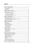
TABLE OF CONTENTS
Overview................................................................................................................................ 5
Introduction: Why Use A Template?................................................................................... 5
Purpose of the ArchiCAD MasterTemplate......................................................................... 8
Template organization and structure.................................................................................... 9
What's Included ................................................................................................................ 10
Download and Quick Tour of the ArchiCAD MasterTemplate .......................................... 11
The View Map.................................................................................................................. 12
Layers, Layer Combinations & Model View Options ........................................................ 15
The Layout Book .............................................................................................................. 18
Setup and Customization ...................................................................................................... 20
Where to Set Up the ArchiCAD MasterTemplate.............................................................. 20
Customize Your MasterTemplate...................................................................................... 21
Cleaning Up Any Warning Messages................................................................................ 23
Enter Your Info into the Title Block and the Title Sheet Placeholders ............................... 28
Importing an Existing Title Block ................................................................................. 29
Boilerplate Placeholders................................................................................................ 29
Starting Your Own Projects .................................................................................................. 31
A New Project Using MasterTemplate .............................................................................. 31
Filling in Project Info........................................................................................................ 33
Starting the Design Process............................................................................................... 34
Steps to Mastery ................................................................................................................... 35
Integrating MasterTemplate into Your Office.................................................................... 35
How To Take An Existing Plan And Migrate It To The MasterTemplate System.............. 36
Synchronizing Layers ................................................................................................... 37
Copying the Model into Your New File ........................................................................ 39
Executive Summary ...................................................................................................... 43
Creating a New Office Template from a Modified MasterTemplate .................................. 44
Remodel Projects: Setup & Strategy ..................................................................................... 46
Concepts and Procedures for Setting Up and Managing Remodel Projects ........................ 46
Analysis........................................................................................................................ 46
Explanation of the Hot Linked Method for Addition / Remodel Projects ....................... 47
Quick Guide to Remodel Projects ..................................................................................... 50
Project Setup................................................................................................................. 50
Project Development..................................................................................................... 50
Summary ...................................................................................................................... 51
Frequently Asked Questions ............................................................................................. 53
Q: Do you break the hotlink in the new addition plan to edit it? .................................... 53
Q: Is the Demo Plan automatically updated as the design changes? ............................... 54
Layer Naming, Use & Management...................................................................................... 55
Background................................................................................................................... 55
The ArchiCAD MasterTemplate Layer Organization ........................................................ 57
Overall Structure........................................................................................................... 57
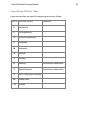
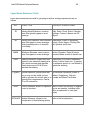
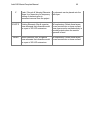
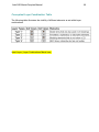
Layer Names Prefixes Table ......................................................................................... 58
ArchiCAD MasterTemplate Manual
3
Layer Name Extension Table ........................................................................................ 59
Additional Concepts and Items of Note......................................................................... 61
A Place for Everything - Example List of Where Elements Belong ............................... 63
Layer Combinations Naming and Use within the ArchiCAD MasterTemplate............... 65
Procedure for updating layer combinations.................................................................... 65
Conceptual Layer Combination Table ........................................................................... 66
Model View Options Naming, Use & Management .............................................................. 67
Project Map Structure | Features ........................................................................................... 68
Stories .............................................................................................................................. 68
Sections ............................................................................................................................ 69
Elevations ......................................................................................................................... 69
Viewing and Adjusting Section and Elevation Markers..................................................... 69
Worksheets ....................................................................................................................... 70
Details .............................................................................................................................. 71
3D Documents .................................................................................................................. 71
3D .................................................................................................................................... 72
Schedules.......................................................................................................................... 72
Project Indexes ................................................................................................................. 73
Lists.................................................................................................................................. 73
Info................................................................................................................................... 74
Help.................................................................................................................................. 74
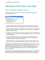
View Map Structure | Features.............................................................................................. 75
Main Categories & General Notes..................................................................................... 75
IMPORTED REFERENCE DOCUMENTS (WORKSHEETS) ........................................ 76
MODELING - DESIGN - LEGENDS............................................................................... 76
MODEL / DESIGN VIEWS ......................................................................................... 76
INTERACTIVE LEGENDS (FAVORITES)................................................................. 78
3D PROJECTED VIEWS ............................................................................................. 79
MODULE VIEWS (FOR EXPORT)............................................................................. 80
CONSTRUCTION DOCUMENT VIEWS........................................................................ 81
Clone Folders................................................................................................................ 81
Other Folders ................................................................................................................ 84
PRESENTATION DOCUMENT VIEWS......................................................................... 84
TRASH - RECYCLE BIN ................................................................................................ 84
Layout Book Structure | Features .......................................................................................... 85
Feature Summary.............................................................................................................. 85
Sheet Organization - Two Systems.................................................................................... 85
The Layout Masters .......................................................................................................... 87
Visual Cues for Text Entry and Project Info...................................................................... 88
Layout Sheet Tools ........................................................................................................... 89
Changing the Layouts to a Different Master...................................................................... 89
Arranging Your Drawings on the Layouts......................................................................... 90
Interactive Legends............................................................................................................... 92
Pre-set Interactive Schedules............................................................................................. 94
Pre-set Section & Elevation Viewports ............................................................................. 95
Pre-set Milled Rafter Tail Feature ..................................................................................... 96
ArchiCAD MasterTemplate Manual
4
Detailer Setup & Use ........................................................................................................ 98
User Required Management | Checklist............................................................................. 99
Working Methods | Standard Practices in ArchiCAD ...................................................... 101
Stacking Drawings in Layout Sheets: .......................................................................... 101
Parameter Transfer Technique..................................................................................... 101
Links to Other Important Explanations............................................................................ 104
EXTRA STUFF removed for possible reuse ................................................................... 105
ArchiCAD MasterTemplate Manual
5
OVERVIEW
INTRODUCTION: WHY USE A TEMPLATE?
When you started to work with ArchiCAD, you installed the software and began to learn
the tools and methods. You may not have thought much about the initial "blank" file that
appeared, ready for you to start to work. In that file, there existed certain layers,
linetypes, fills, composites, materials etc. (collectively called Attributes) as well as a
basic structure (stories, views, layout masters and layouts). That file was created from a
startup "template".
There is a startup template file built into ArchiCAD by Graphisoft. You can access it by
doing a New and Reset (hold down the ALT or OPTION key and choose File menu /
New and Reset). The basic settings in this file are workable, since they include a variety
of attributes and some structure, but will need to be augmented by the user in order to
successfully produce a model and construction documentation.
Graphisoft provides in each region a localized template to create a new project when
you choose New File from Template. For example, in ArchiCAD 13 in the United States,
that template is called ArchiCAD 13 Template.TPL. It has more attributes (materials,
fills, layers, etc.) and a more developed structure than the built-in template, however it
still leaves a lot of setup work for individual users. This is understandable, since
Graphisoft chooses to give a base on which to build, one which is easily understood
(simplified) and relatively universal (most everything will be relevant for most users).
There are several alternative options when you start a project. If you choose File menu
> New file > Use Current Settings, you will carry forward (from the last file opened or
worked on) all of the Attributes, but only a bare minimum of structure. While Attributes
such as Layers and Layer Combinations, Materials, Fills, etc. will be inherited, the
structure will be minimal, with almost no Views or Layouts to start out. This is a far
inferior approach to starting a new project with a template, since you will have to set up
so much from scratch.
Once you have worked with ArchiCAD for a while and produced several projects, you
may have developed your own template, either explicitly or simply by your work
process. It will have the attributes you have found that you need, be personalized with
your title block, and be a familiar environment in which to design.
To create a template explicitly is simple: take any project that you are satisfied with, and
save the PLN as a template file (File menu > Save As > Template - TPL file). Then,
when you start up a new project, you may choose New File from Template, and browse
for the TPL file you saved. After opening it, ArchiCAD will rename it Untitled, so you will
ArchiCAD MasterTemplate Manual
6
not inadvertently overwrite the template, and will prompt you when for a name and
location when you Save the PLN file.
If you save an entire project (building and all) as a TPL file, of course you will need to
delete the old building before starting a new one. It makes sense to do this BEFORE
saving as a TPL, since otherwise you will have to do this every time you start a new file.
However, you don't have to delete everything: you may retain anything you might use in
future projects, including Elevation and Section markers which define corresponding
Views that are placed onto Layout Sheets. In your new project, you will simply need to
move these markers into the appropriate locations for the new building. You will see that
those Elevations and Sections are still (already) placed on Layouts and will happily
update when you request them to show the new design. Similarly, detail drawings you
use in multiple projects can be retained in the TPL file so that you do not have to draw
them again or re-import them.
You can get a similar benefit without using a template, by simply saving a copy of a
recent project under a new name, then deleting the building and anything else you won’t
need in your new project. Since it takes time and conscientious effort to delete certain
things but leave others in place in an organized way, it makes sense to do this carefully
and save the file for later reuse when starting the next project. This is the ultimate
rationale for creating an optimized template - saving time and effort when starting and
running each project.
This is the key to the ArchiCAD MasterTemplate. There is a tremendous amount that
can be set up ahead of time in a robust template file, to save time and improve
consistency within and between projects. ArchiCAD resellers and consultants have
traditionally offered services to set up office standards and templates, and some have
published or sold their templates. In the U.S., there have been templates from Rex
Maximilian (MaxATS), Eric Batte (Standardized Template System
http://www.getstandardized.com), and AEC Infosystems
(http://www.aecinfosystems.com). We are indebted to these people and companies, as
well as to many of our own local users such as Van Hohman (Fonda-Bonardi and
Hohman Architects), Tamir Barelia, Vincent Moretti, Erika Epstein and others who have
shared their ideas with us at ArchiCAD User Group meetings over the years.
We have attempted to synthesize all of our years of experience working with the
program (I have 20 years, Scott has 14 years) with all the bright ideas we have seen, to
create the best startup template possible: the ArchiCAD MasterTemplate.
We set it up, so you don't have to…
ArchiCAD MasterTemplate Manual
We wish you the best success and enjoyment using ArchiCAD. We know that
MasterTemplate will help you work faster and get better and more consistent results.
Please give us your feedback via email or the AMT Support Forum.
Eric Bobrow
Creator of the ArchiCAD MasterTemplate
7
ArchiCAD MasterTemplate Manual
8
PURPOSE OF THE ARCHICAD MASTERTEMPLATE
•
A starting environment that allows a streamlined workflow, with the objective of
getting better work out more quickly with less frustration and fewer errors.
•
Enhances both the modeling & construction document process.
•
After initial use that includes first time setup, never again waste time recreating a
project file or settings.
•
Create a repeatable and reliable office standard, thereby reducing errors.
•
Make the best use of ArchiCAD’s automated features.
•
Foster office standardization.
•
Designed to teach at the same time as providing a working framework.
•
What the template is NOT:
•
one-size-fits-all
•
perfect without any changes
•
resistant to improvement
The ArchiCAD MasterTemplate is fully customizable, yet designed to be used out of box
with minor ‘fill in the blanks’ items.
ArchiCAD MasterTemplate Manual
9
TEMPLATE ORGANIZATION AND STRUCTURE
It may be useful at this point to describe architectural projects designed and
documented in a CAD or BIM system as being comprised of four inter-related schema:
Geometry: the actual form, shape and materials of the building design; also the
geometry projected into standard orthographic drawings (e.g. plans, sections,
elevations, details)
Annotation: the text, labeling, call-out markers and dimensioning that describe the
building in each drawing
Attributes: the line-types, wall types, layers and layer combinations, fills, materials that
are used to depict and control the appearance of geometry on the drawings
Structure: the relationships
•
between annotated, attributed geometry and actual drawings (e.g. View
definitions of layer combination, scale, model view options, etc.),
•
between each drawing and other related ones (e.g. plans to sections to
elevations and from any of these to detail drawings),
•
between elements in the design and the schedules used to tabulate and
summarize them,
•
between the drawings and the layout sheets, and
•
between drawings or layouts and various output sets (e.g. print or plot sets,
submissions of files to consultants, etc.)
A template in a CAD or BIM system in general does not contain an actual building
design, nor the annotations of any particular building. However, it is best if it contains all
or most of the attributes needed to describe buildings in the system, plus as much
structure as can be set up ahead of time. This will minimize the work getting each
project started, guarantee consistency between projects as well as within each project,
and streamline the workflow in a variety of ways.
The ArchiCAD MasterTemplate contains both Attributes and Structure preset and ready
to go.
•
•
Optimized layer naming system
Extensive layer combinations
ArchiCAD MasterTemplate Manual
•
•
•
•
•
•
•
•
•
•
•
10
Coordinated Model View Options
Predefined Autotext fields ready for data entry pre-placed onto layout sheets
Pre-defined Views in the View Map
Pre-defined Master & Layout Sheets
Pre-placed Drawings on Layout Sheets.
Detailer template and modules fully integrated
Example penset systems to be considered in evaluation of your own system
Integrates the best free third party library parts
Included modified interactive schedules
Sample complex profiles for rafter tails, street roadwork, walls with framing, etc.
Typical project folder structure - a place for everything, everything in its place
WHAT'S INCLUDED
The ArchiCAD MasterTemplate is made up of the following:
•
ArchiCAD MasterTemplate.TPL (a blank template file you will customize, then
use to start your next project)
•
MasterTemplate SAMPLE.PLN (an example demonstration project) as well as
MasterTemplate SAMPLE REMODEL-ADDITION.PLN (an example of a
remodel project)
•
MasterTemplate LIBRARY (a folder containing the supporting library, modules,
preferences and favorites)
•
AMT PROJECT FOLDER (a sample folder structure for your project data)
•
AMT DOCUMENTATION (this manual, the QuickStart Guide, and other
supporting files)
ArchiCAD MasterTemplate Manual
11
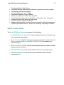
DOWNLOAD AND QUICK TOUR OF THE ARCHICAD
MASTERTEMPLATE
Please follow the instructions supplied with your purchase to download the template
files. They are supplied as a single large Zip archive file (or multiple smaller Zip files),
and will need to be extracted or expanded into a folder somewhere on your workstation.
Place this AMT folder wherever convenient for now, such as on your Desktop. Later
we'll discuss strategies for where to store your template files, which will vary depending
on whether you are working alone or setting this up for a whole office.
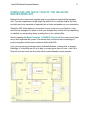
Start by opening the MasterTemplate 13 SAMPLE Project.pla file to see how we have
set up and organized this system. We assume that you have a basic knowledge of
project navigation and the menu structure within ArchiCAD.
If you get any warning messages about Hotlinked Modules, missing links to external
Drawings, or Views that are not up to date, you may ignore them for now - click OK or
Skip until you get to see the floor plan of this small residential project example.
ArchiCAD MasterTemplate Manual
12
THE VIEW MAP
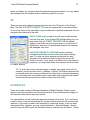
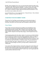
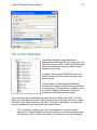
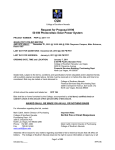
Once this simple file is open, if you glance at the Project Map, you will see just a few
stories, elevations, sections, worksheets, etc. It is, after all, just a small two story house.
However, when you look at the View Map, you will discover there are close to 200
predefined Views, grouped into four major categories:
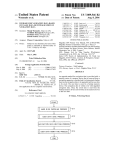
When you open the main View folders to the next level, you will see additional
subgroupings:
ArchiCAD MasterTemplate Manual
13
Some of these (e.g. Design Sketches or Web Downloads) are empty folders, others are
folders that contain preset views, and some are "Clone" folders (more on that later). We
suggest you explore by opening up these folders and double-clicking each View to see
all the different ways the project information can be represented. The beauty of this
system (and ArchiCAD itself) is that most of these Views will show appropriate
information without any effort on your part: simply model the building, and the View will
be ready for you to annotate.
NOTE: The TRASH - RECYCLE BIN folder is available for you to place anything you
don't need but want to save for later use, such as Detail Folders while you are in early
design.
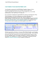
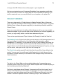
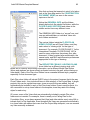
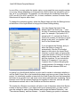
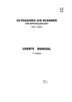
As you activate each View, ArchiCAD will set the Layer Combination, Scale and Model
View Option based on the View Settings. In the Properties area at the bottom of the
Navigator View Map, you’ll see this information displayed:
Notice that the Layer Combinations and Model View Options (MVO) have similar names
(e.g. Layer Combination = CONDOC | M-E-P SYSTEMS; Model View Option = CON
DOC | M-E-P SYSTEMS PLAN).
Each Layer Combination is unique, while a number of the MVOs are essentially the
same; we have opted to create additional (duplicate) MVOs to make it easier to
correspond the right MVO with each Layer Combo.
ArchiCAD MasterTemplate Manual
14
Since the View Settings are already saved with the correct combinations, most of the
time you won’t have to think about choosing a MVO to go with your Layers for a
construction document.
ArchiCAD MasterTemplate Manual
15
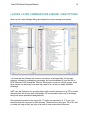
LAYERS, LAYER COMBINATIONS & MODEL VIEW OPTIONS
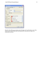
Open up the Layer Settings dialog and explore the Layer naming conventions.
You'll see that we followed the common convention of a single letter for the main
category followed by subcategory groupings, but have broadened it from the AIA or
NCS (National CAD) standards. There is little reason to use just 4 letter groups, since
layer names can be longer now than they used to be, so we use easily readable
phrasings.
AMT uses the Extension for grouping layers with common purposes (e.g. 3D for model
elements that will also be seen in drawings, 2D for annotation seen only in drawings,
along with some specialized designations).
One special innovation is the use of the "U" prefix (as opposed to A, C, E, etc.) for
elements that are only seen in ONE drawing. These can be of any type, 3D or 2D, text
or model, as long as they are only to be seen in one construction document.
ArchiCAD MasterTemplate Manual
16
For example, the Electrical Plan will include some objects (receptacles, switches, etc.),
text, labels and perhaps dimensions that are only on that drawing. These elements go
on the U | ELECTRICAL layer. This convention makes it easier to decide which layer to
put things on.
For visual clarity, AMT uses vertical “pipe” separators ( | ) rather than dashes ( - ) to
break up phrase groups in layers, layer combos, MVOs and other lists. We feel it makes
it easier to scan the lists.
TIP: The “pipe” character is not used very frequently, and some users have
asked where to find it on the keyboard. It is usually on the far right side, in the
middle section above the backslash (“\”) character.
An alternate set of layer names is available for compatibility with industry standards
such as the AIA, National CAD Standard (NCS) or the Uniform Drawing System (UDS).
These layer names are set up in an NCS-UDS Attribute Manager (.aat) file which makes
it easy to switch at any time during the project lifecycle if your firm prefers or needs to
use this layer naming system.
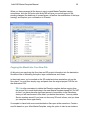
Layer Combinations have been defined for all standard drawings as well as for
modeling, detailing and other dedicated activities. Note that as you activate each Layer
Combo, layers that are hidden are also LOCKED, which allows them to be omitted
when you are using popup palettes to choose which layer to place an element. This
makes the layer popup list much shorter, allowing you to see only the appropriate layers
for each construction document View. Be sure to set your Options menu > Work
Environment > Dialog Boxes and Palettes to “Hide Locked Layers in Popup Palettes.”
ArchiCAD MasterTemplate Manual
17
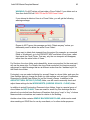
Below are two examples of the Layer menu popup seen when the CONDOC |
ELECTRICAL layer combination is active. On the left is what you see when the “Hide
Locked Layers” is NOT checked. It shows the beginning of a long cumbersome list of all
the Layers, including ones that are currently hidden since they are not relevant to
electrical drawings.
Choosing the appropriate layer from such a list is much more effort than working with
the one on the right, when the “Hide Locked Layers” is checked. It shows ONLY the
layers that are visible for electrical work, a much simpler list to work with!
This Work Environment preference is included in the AMT Work Environment profile
(supplied with AMT) that you can import, which sets up a number of useful options.
Please see the appendix for how to use the AMT Work Environment Profile.
ArchiCAD MasterTemplate Manual
18
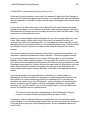
THE LAYOUT BOOK
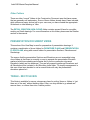
Explore the Layout Book as well. The simple structure of the Layout Book (see graphic
below) includes the skeletal form that can grow to handle projects of any arbitrary size.
Open up the subset folders as well as the Masters and explore the layout sheets to see
what has been set up.
You’ll see that we have two sets of layouts, one based on a simple numerical sequence
(drawings A.01 through A.15 in the SMALL PROJECT EXAMPLE SET) and the other
based on hierarchical category Subsets (e.g. A300 series for the BUILDING PLANS,
A400 Series for the EXTERIOR ELEVATIONS, etc.).
In your office, you may prefer the simpler option or may need the more complex system,
or you may change depending on the project size. Both of them are included for you to
use “as is” or to customize. For example, you can change the numbering format from
ArchiCAD MasterTemplate Manual
19
A3.01 and A3.02 to A301 and A302, etc.; or insert, renumber, rename or reorder these
Subsets and all Layouts within them.
Pay particular attention to the Title Page layout, on which there are a multitude of
Autotext entries placed directly on the sheet. Many of these are set up in the Project
Info database and will automatically update when information is entered or changed.
Experiment by opening up the File menu > Info > Project Info command and filling in
some of the data there, then return to the Title layout to view the result.
NOTE: As a convention in MasterTemplate, uninitiated entries in the Project Info have
multiple asterisks (e.g. ***PROJECT NAME***) to make it easy to spot information that
has not been initialized or filled in.
Remember, all that is in this sample file is in the actual ArchiCAD MasterTemplate,
which is fully customizable to suit your needs.
For now, our brief tour of the sample file is done. We will point you to this file at other
points in the manual to illustrate other features and techniques.
ArchiCAD MasterTemplate Manual
20
SETUP AND CUSTOMIZATION
WHERE TO SET UP THE ARCHICAD MASTERTEMPLATE
•
ArchiCAD MasterTemplate Folder location.
•
Projects Folder structure and location
•
Template Support Files & Folder
For sole practitioners, we suggest that you set up an ArchiCAD Office Standards (AOS)
folder inside your Jobs or Projects folder (where you keep all current projects). In a
multi-person office, the AOS folder should be located on your server in a location
accessible by all team members.
When you downloaded and extracted the template files, you placed them on your
Desktop or some convenient place. Keep the original download files safe as a backup
or reference, then place a copy into your ArchiCAD Office Standards folder.
The AOS folder should contain the AMT (MasterTemplate) folder, as well as other
support files used in your office for working in ArchiCAD, such as custom libraries,
collection of detail drawings, boilerplate PDFs and Word files for placement into
construction documents, etc.
ArchiCAD MasterTemplate Manual
21
CUSTOMIZE YOUR MASTERTEMPLATE
You will need to customize the ArchiCAD MasterTemplate to have your firm's
information in the title block and on the Title sheet. Since the AMT is an
ordinary ArchiCAD PLN project file saved as a TPL template file, you can modify
anything else you wish, right away or at a later date.
First, you'll need to duplicate the original AMT file to create your personal copy. Using
Windows Explorer or the Finder (rather than from inside a dialog box while
running ArchiCAD), navigate to the AMT folder. Select the ArchiCAD
MasterTemplate.TPL file and right-click to Copy, then immediately afterwards right-click
in the same folder and Paste. You will now have a duplicate AMT file. Rename it Office
MasterTemplate.tpl or ABC Architects MasterTemplate.tpl or anything you wish.
You now have a custom template you will make specific to your office.
Whenever you wish to customize or revise your Office MasterTemplate, you will need to
open it up differently than you when you start work on an actual project. Start ArchiCAD
and choose Open File > Browse for File (or with ArchiCAD already running, go to the
File menu and select Open). In the Open File dialog box, choose as the file type (from
the popup) "TPL Template File" (or "All Files"), and navigate to and select your new
custom Office MasterTemplate.tpl file (or whatever you named it).
ArchiCAD MasterTemplate Manual
22
When opened in this fashion, you will have access to revising and resaving it most
easily. You will see its file name at the top of the screen, rather than Untitled.
TIP: This is very important! If you see Untitled at the top of the screen instead of
the name of your office template, any changes you make will not be automatically
saved to your custom template. We suggest you close the Untitled file, and
open your Office MasterTemplate.tpl again in exactly the way just described, so
you have proper access to the file.
ArchiCAD MasterTemplate Manual
23
CLEANING UP ANY WARNING MESSAGES
Normally a Library Manager dialog will not appear when you load the file. If the Library
Manager dialog pops up, you will need to tell ArchiCAD where to find the appropriate
libraries. ArchiCAD will find the MASTERTEMPLATE LIBRARY folder without prompting
as long as you leave it next to the Office MasterTemplate.tpl file in the AMT
folder. Similarly, it will find the standard ArchiCAD Library folder, unless you have
moved or changed the path.
However, if you need to show the Library Manager where either of these folders are
located, you may click the Add… button at the top of the Library Manager dialog box.
Navigate to and select the appropriate folder, then click the Choose button to add it to
the list of libraries to load. (If you have any problems or questions on how to do this,
please email us or contact your ArchiCAD reseller for guidance.) This will be
remembered the next time you open or use the AMT file.
One of the messages you will get the first time you open AMT will refer to missing
Hotlinked Module files.
Since these support files are not found in their original location (on the computer where
they were created), you will need to help ArchiCAD find their current location on your
workstation or network. Click OK, we’ll get that cleaned up shortly.
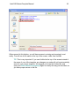
You may also get the standard Update Drawings warning message:
ArchiCAD MasterTemplate Manual
24
You can ALWAYS ignore this message (press Skip All) for any ArchiCAD file, UNLESS
you intend to immediately print out drawings. It simply is telling you that some of the
Drawings in the project (on the Layout sheets or elsewhere) have not been checked and
may not be up to date. If you click Update All, it will take a long time, and it’s absolutely
not necessary UNLESS you are about to print or plot. If you wish, you may check the
“Do not Display this dialog Next Time” to avoid seeing this message.
TIP: You may Update All the Drawings at any time (particularly just before you’re
going to print out a drawing set or send out some DWG or PDF files) by going to
the File menu > External Content > Drawing Manager, selecting all the Drawings,
and clicking the Update button.
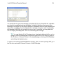
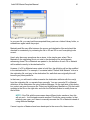
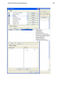
To clean up the missing Hotlinked Modules warning, after you finish opening AMT, go to
the File menu and select External Content > Hotlink Manager.
ArchiCAD MasterTemplate Manual
25
Click on the AMT Legends file (the first one in the list). Then select Relink…from File:
ArchiCAD MasterTemplate Manual
26
Then in the dialog box, navigate to the AMT folder, select the AMT Linked Files folder
and find the corresponding AMT Legends file:
ArchiCAD MasterTemplate Manual
27
TIP: If you have recently been using MOD files for Hotlinked Modules in a
project, the “Files of type” popup may be set for “ArchiCAD Module File (*.mod);
in this case you’ll need to manually change the popup to “ArchiCAD Solo Project
(*.pln) as you see above.
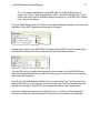
Click the Select button, and you’ll return to the Hotlink Manager dialog box and see that
the Status of the AMT Legends has changed to Relocate:
Repeat the process for the AMT Office Favorites and the AMT Project Favorites (they
are located in the same folder), so that they all have the Relocate status:
Click the OK button to confirm the changes you have made, and ArchiCAD will then
read the Hotlinked Module files to make sure they are up to date. After a few seconds,
the process will complete.
Now all the Hotlinked Modules (HLMs) will "know where they live". We'll be exploring
these HLMs later on in this manual. You should only have to do this process once, as
this will be recorded by ArchiCAD in the template file and in copies made from it.
Save your template file at this point (simply File menu > Save or use the keyboard
shortcut), to make sure this information is stored and will not have to be repeated.
ArchiCAD MasterTemplate Manual
28
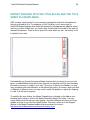
ENTER YOUR INFO INTO THE TITLE BLOCK AND THE TITLE
SHEET PLACEHOLDERS
AMT contains ‘place holders’ for your company information and other boilerplate text
that you will need to fill in. For example, on the Title Block, you’ll see a logo for
ArchiCAD MasterTemplate that should be replaced by the appropriate graphics and/or
text for your office. Below that, you’ll see a grey text box that is intended to be used for
standard disclaimers. There is also a space for a seal which you can “wet stamp” or fill
in digitally if you wish.
Systematically go through the various Master Layouts that you intend to use (you can
ignore or delete Masters with sheet sizes that are not relevant) and fill in your company
information and logo to "make it your own." Once you do this for one Master, you may
copy and paste onto other Masters, so this should go quickly. Of course, when you work
on Masters of different sizes, you may need to scale the graphics or adjust the spacing
in order to fit the layout properly.
To simplify this even further, the MasterTemplate logo is placed on the Master as a
Drawing that is linked to a file in the MasterTemplate Linked Files folder. You may
simply replace that file with your own graphic, and all the Masters will show your logo
graphic as soon as you click the Update button. We have a video tip in the Support
section of the MasterTemplate website that shows how this is done:
http://www.archicadtemplate.com/support/company-logo/
ArchiCAD MasterTemplate Manual
29
Importing an Existing Title Block
If you have a complex title block in ArchiCAD or another CAD system, you may prefer to
import your old title block into MasterTemplate and integrate it into the Master Layouts.
If it is in ArchiCAD, you can copy it from a previous project in several different ways.
The simplest way is to open two instances of ArchiCAD, then select items and copy
from the Master of the old project, and paste into your new template Master.
Alternatively, you can use the Project Chooser popup button in the upper left of the
Navigator and select Show Organizer. Then use the Project Chooser again in the
Organizer and Browse Project… for your existing file. Once its loaded on the left side,
you can switch to the Layout Book on the left side of the Organizer, and drag one or
more Masters from the old project into your active file (the MasterTemplate).
If your existing title block is in another CAD system, you may place a DWG file as a
drawing (File menu > External Content > Place External Drawing…) on either a blank
layout or a Master, then explode it (Edit menu > Reshape > Explode).
In either case, carefully delete anything you don't need from your old title block (for
example, graphics and Autotext that are already included in the MasterTemplate). Get
rid of placeholders or graphics from the Master that you will be replacing. Then move
the desired content into position onto the Master.
TIP: For safety, you may want to do your initial editing on a copy of a Master. To
copy a Master Layout, drag it into a new position in the Master list while holding
down the Control key (PC) or Option key (Mac). To work on the new copy,
double-click it in the Master list.
Once you have the Master copy looking the way you like, you may Select All and
Copy, then go the original Master, Select All and Delete, then Paste. Delete the
Master copy after you verify that the Master is working correctly.
If you update the default Master that is used in MasterTemplate, all Layout sheets that
refer to it will update automatically with the new contents. If you create or update other
Masters, the contents will be seen when you assign this Master to some or all Layouts.
You can change the Master for multiple layouts by selecting the Layouts in the Layout
Book list, then clicking the Settings and specifying the new Master in the dialog box.
Boilerplate Placeholders
On the Title Sheet Layout and on some of the other Layouts, placeholders are identified
as framed text boxes with grey backgrounds. These may be edited directly on each
ArchiCAD MasterTemplate Manual
30
specific sheet.
Flip through the actual Layout pages in the template, and anywhere there is a
placeholder grey box, fill in whatever you can that you expect will be common from one
project to another. Remember that whatever you place into your template will save you
time in every project, and will always be editable as needed.
After you have entered all of your office and boilerplate information, it is very important
to Save your work. ArchiCAD will automatically overwrite the TPL file with the latest
version, as long as you opened it up the way we instructed above.
Once you have customized your standard office template you will follow the instructions
below to start each new project. If you would like to edit or rework your template, follow
the special instructions above to open the Office MasterTemplate.tpl file for revisions.
ArchiCAD MasterTemplate Manual
31
STARTING YOUR OWN PROJECTS
A NEW PROJECT USING MASTERTEMPLATE
Start up ArchiCAD and choose New File / Use a Template; or if ArchiCAD is already
running, choose File menu / New… then specify Use a Template. The first time, you'll
need to browse for your Office MasterTemplate.TPL, the one you have modified to
include your office standards.
ArchiCAD MasterTemplate Manual
32
Any subsequent time, it will be simpler: you will see its name highlighted in the recent
Templates popup list.
ArchiCAD MasterTemplate Manual
33
FILLING IN PROJECT INFO
After you start each project, you will want to go through the File menu > Info > Project
Info and fill in whatever fields you can:
Press down on the triangle to popup a text entry area which supports multiple lines.
Remove the asterisks (***), which are included simply to make it easier to see which
fields have not yet been entered.
Some entries may not be known yet, or not be appropriate to this project, and you may
leave them unchanged. You can return here to fill in this info at any time, and it will
update on the Title Block and on the Title Sheet.
The file will initially be labeled ‘Untitled’, and require you to ‘Save As’ with your desired
project name. Make sure when you "Save As" to choose PLN format (ArchiCAD
Solo Project), and name as desired (e.g. 07123 SMITH HOUSE.PLN). Save the PLN
into its own project folder (e.g. 07123 SMITH) inside your Jobs folder.
TIP: The ArchiCAD MasterTemplate folder contains a sample MasterTemplate
NEW PROJECT FOLDER. This folder has many subfolders ready to hold typical
project information. Look in the PROJECT FOLDER section later in this manual
for more guidance on its use and customization.
ArchiCAD MasterTemplate Manual
34
STARTING THE DESIGN PROCESS
You are now ready to begin laying out your building or site. Be sure to review and adjust
the number of stories and floor-to-floor elevations as needed. This can be done in the
Story Settings Dialog Box under the Design Menu. See the manual section for SEA
LEVEL OR PROJECT LEVEL for guidance on how to move the building elevations in
the Story Settings to match actual survey elevation data if desired.
Construct the model and site as you normally would. You will have to adjust the
locations of the pre-placed section and elevation markers.
There are two pre-drawn slabs in MasterTemplate that represent in a simple way the
adjacent exterior grade. You may need to adjust its vertical elevation to account for the
relative relationship between grade and the first story level or project zero. You can also
discard these slabs and replace it with one or more Mesh and/or Slab elements when
you are ready to represent topography in a more detailed manner.
Depending on the size of your building, additional adjustments may be required for the
boundaries and locations of the pre-placed drawings in the Layout Book.
ArchiCAD MasterTemplate Manual
35
STEPS TO MASTERY
INTEGRATING MASTERTEMPLATE INTO YOUR OFFICE
This template is set up so that when used correctly, Views of your model will be
automatically generated. Many of these are preplaced as Drawings on predefined
Layout Sheets, often requiring only slight repositioning to be ready for output.
Using the template correctly entails proper project setup, accurate modeling, and most
importantly, making sure entities or elements are placed on appropriate layers. As an
example, if you place an exterior wall on a layer intended to receive a roof, the wall will
not display correctly, and the resulting Views will misrepresent the desired outcome.
Therefore it is critical that careful attention is paid to which layers modeling and
annotation items are placed upon.
Layer Combinations and Layer Names have been carefully pre-set to achieve this,
however occasion may arise where slight modifications to either of the mentioned Layer
controls are necessary. Layer Combinations must be properly updated following
standard procedure when new Layers have been added, or existing Layer names are
changed.
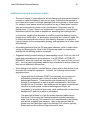
TIP: If you add a new Layer to your template or a project file, select the added
Layer in the right side column of the Layer Settings dialog box, then start at the
top of the Layer Combination list on the left hand side and set the visibility, mode,
interaction and locking attributes for each Layer Combination. When completed,
click OK to save your updated settings.
One important issue to be aware of is file contamination. This generally occurs when
elements are copied from legacy projects (prior to using the MasterTemplate), and
pasted into the MasterTemplate. For example, there may be a well designed window
system that exists in an earlier project, with the complex set of parameters already
defined. The instinctive move is to copy the wall containing the window and paste it into
the new project. The issue with this is that all attributes attached to those elements will
be pasted in as well, including line types, materials, fills and layers.
When a user desires to paste in an item from a different file, it is recommended that
those items either be placed onto a layer that also exists in the destination file, or as an
alternate, first copy or move the item onto the ArchiCAD Layer, then copy and paste
it into the new project, after which the items are moved onto the correct layers. Setting
fills and materials to match those in the destination file is also beneficial, however this
may not always be practical.
ArchiCAD MasterTemplate Manual
36
HOW TO TAKE AN EXISTING PLAN AND MIGRATE IT TO THE
MASTERTEMPLATE SYSTEM
There are two main tasks to accomplish when migrating an existing project into your
new office standard template. The first one is to synchronize the layers in the project to
match those in the template. The second is to copy the information (the building and
annotation) from the existing project file into the new one based on the template.
Migrating a PLN file is straightforward when the project is relatively early in
development. In the simplest scenario, there is a 3D model with annotation on the floor
plans, but nothing else developed beyond what ArchiCAD generates automatically in
sections and elevations. Migration gets more complex as 2D work is done in sections
and elevations, markers are placed for detail drawings, and details and worksheets are
created. It is always possible to migrate a project into a template, but at a certain point,
the effort may not be worth it.
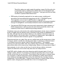
TIP: We suggest that before doing major surgery on your file, you save all your
current work, and then Save As a “working copy” of the PLN under a new name.
In case you do something wrong, you can always go back to the previously
saved version.
ArchiCAD MasterTemplate Manual
37
Synchronizing Layers
The best way to synchronize layers is to go through the layers you have used in your
existing project, and rename them carefully to match the names in the template.
To reduce your work to the minimum, in your “working copy” of the project file, get rid of
the layers you have not used in your project file. Open Attribute Manager (Options menu
> Element Attributes > Attribute Manager) and select the Layers tab in the top left to see
the Layers in the current file. Note that layers that currently have elements placed on
them will have a check (“in use”) while unchecked layers are currently empty of content.
Click the Purge Unused button at the bottom of the Attribute Manager. That way you
may have only 10 or 20 layers to rename, rather than 50 or more.
TIP: We don’t suggest you do this on a project normally, since you will eliminate
layers that you may need to use later on in the project lifecycle.
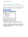
Next, click the Open… button on the bottom right of Attribute Manager and select a
copy of your office MasterTemplate file. You will see the Layers in the template listed on
the right hand side. If you have the lists sorted by Index number (you may need to click
the # icon button to sort the list using that column), you may notice that the names of
layers correspond in many cases. For example, Layer 1 in the standard USA template is
called A-WALL-EXTR, while in MasterTemplate it is called A | WALL | EXTERIOR.3D.
ArchiCAD MasterTemplate Manual
38
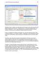
Wherever there is a match, you may simply select the layer on the right-hand side (from
MasterTemplate) and click the <<Overwrite button. In the screen-capture above, you
will see that layers 2, 6 and 7 have already been done using this method, and their
names on the left side are now based on MasterTemplate conventions.
Layer 9 is highlighted and about to be copied over. The layers with this index number
correspond nicely (i.e. A | FLOOR | STAIRS + LANDINGS + ELEVATORS.3D is a good
match for A-FLOR-STRS). Simply clicking the <<Overwrite button will match the layer
name.
The reason why many of these names will match nicely is that when we created
MasterTemplate, we did the inverse: we changed the name of each layer to suit our
new standard convention. So, for “standard” layers in the USA template, and many in
the International template, the layers will match but of course have different names that
need to be reconciled using this process.
However, it is likely that there are some layers that do not match properly by index
number. In that case, using the <<Overwrite button will cause some confusion, since
elements placed on that particular layer will now be on a layer that has a name
indicating a different purpose or usage. In this case, it may be best to manually rename
the layer to match a suitable MasterTemplate layer (including the layer extension, which
is seen following the dot or period - e.g. “.3D”) so that these elements come into the
template already sorted properly.
ArchiCAD MasterTemplate Manual
39
When you have renamed all the layers in use to match MasterTemplate naming
conventions, click the OK button and ArchiCAD will give you a short report of the
pending changes (the deletions of unused layers, as well as the modification of the layer
naming), and request your confirmation to Proceed:
Copying the Model into Your New File
At this point you may bring the floor plan and 3D project information into the destination
file without fear of disturbing the layers, layer combinations and Views.
In the simple case, you've worked on the 3D model and done annotation only on the
floor plans. You may then simply copy and paste from the original project PLN file into
the destination PLN.
TIP: It is often convenient to delete the Elevation markers before copying from
the source file to avoid duplicates in the new MasterTemplate-based file. Do NOT
do this if you have placed a significant amount of annotation in the Elevations,
since you will lose access to this data if you delete the markers. You may delete
Section markers as well if you have not done any 2D work in them, and you know
you can place them again easily.
It’s simplest to have both source and destination files open at the same time. Create a
new file based on your office MasterTemplate, using the option to start a new instance
ArchiCAD MasterTemplate Manual
40
of ArchiCAD so you can keep the source file open too.
In the new file, before pasting in the model, it's important to adjust the Story Settings in
this new file to match the original project settings. You can refer back and forth between
the two instances of ArchiCAD to make sure the names and heights of the stories match
properly.
In your source file (the working copy of the original PLN file which has had the layers
purged and renamed), turn on and unlock all layers, draw a heavy marquee (the option
that references all stories) around the building and site and select the Edit menu > Copy
command or use a keyboard shortcut.
Switch to your new template-based destination file, go to the corresponding story, and
Paste. When asked, confirm which story of the source file matches the story you
currently have open in the destination file. You may adjust the Paste marquee to move
the building into a good position relative to the existing template setup, or use the Paste
into Original Position if needed to correspond with external reference files such as
surveys.
Once you've pasted in the plan information (the model, annotation and markers), you
may need to adjust the elevation and section markers. If there are duplicate markers
(e.g. you had elevation markers in your original PLN that came in from the paste),
carefully choose which markers to delete. You may delete the ones from your original
PLN, and move the template-based destination file markers into proper position, so their
Drawings already placed on Layouts will show the new model. Or alternatively, you may
delete the pre-placed destination file markers, and later go to the Drawings on the
Layout sheets and using the Drawing Manager, relink them to the appropriate source
marker.
If you had annotated your original Elevation or Sections, or created Details or
Worksheets, this work will have to be recreated, or copied and pasted manually from
the original PLN to the corresponding View in the destination file. In sections and
elevations, be careful not to copy 3D elements, as they will paste into the destination
section or elevation as 2D linework, causing unnecessary duplication and possible
confusion. To copy 2D elements only, you can use Edit menu > Find and Select and
choose 2D Elements from the topmost criteria.
TIP: Be sure to use the option when pasting to "Place Elements in Original
Location" to make sure that everything lines up the way it should.
If necessary, load any libraries that were used with the source file including specific
project libraries. If you had Embedded Library Parts, you may save them into a folder on
your hard drive by using the Library Manager button “Export embedded subtree into
Local Folder”:
ArchiCAD MasterTemplate Manual
41
In your new file, you may load these exported library parts as a Linked Library folder, or
embed them again inside the project.
Materials and fills may differ between the source and destination files and should be
checked for consistency by reviewing the file in 2D and 3D to see if everything looks
correct.
Here's why there may sometimes be an issue: in the simple case, when Fills or
Materials in the originating file do not exist in the destination file, and elements
referencing those Fills or Materials are pasted in, the definition of each Fill or Material
will be added correctly to the destination file.
However, if a Fill or Material name exists in both files, the definition will not be modified
in the destination file. For example, if a material called "Default Wall Material" is blue in
the originating file, and grey in the destination file, walls that were originally blue will
become grey when pasted in.
In that case, you will need to either overwrite the destination attribute with the one(s)
from the originating file, or recreate them manually. You can overwrite Fill or Material
definitions in the destination file using Attribute Manager. On the right side of this dialog
box, select and open the source file. Select and highlight any Materials or Fills that need
updating in the file on the right side, and click the Overwrite button to modify those on
the left side.
NOTE: If the Fills with the same name have different index numbers, then this
will not work - it will instead overwrite another Fill with the same number. In that
relatively rare case, you'll have to manually recreate the Fill or Material instead of
using Attribute Manager.
If some Layouts or Masters have been developed in the source file, these can be
ArchiCAD MasterTemplate Manual
42
brought into the destination file using the Project Chooser. In the destination file, select
from the Project Chooser popup (by pressing the button at the top left-hand side of the
Navigator palette) Show Organizer. This will open up a double-wide version of the
Navigator. Press down again on the Project Chooser button, and this time select the
source project, which will be in the list of "running" projects if you have been actively
copying information from it.
On the top left-hand side of the Organizer, choose the Layout Book option. You'll then
see the Layouts and Masters of the originating file, and can drag these to the right-hand
side to copy them into the current file's Layout Book.
ArchiCAD MasterTemplate Manual
43
Executive Summary
To import an existing model (3D and floor plan elements only) into a template:
•
Make sure the story settings in the destination template file match those in the
source file. Load any libraries that were used with the source file
including specific project libraries.
•
Delete the modeling slabs in the destination template file, as the source will likely
have its own base or mesh.
•
It is best to synchronize layer naming between the two files, by renaming all
layers in use in the source file to match corresponding layers in the destination
template-based file. (If layer names are present in the source file that are not in
the destination file, these layer names will be added when elements are pasted
in, however they will not be correctly managed by the layer
combinations. Combinations would require updating to address this.)
•
In the source file, turn on and unlock all layers with information that should be
transferred, then draw a multi-story marquee around entire model. Copy,
then switch to the destination template-based file. Make sure you are on the
same story as that which was used during the Copy operation. Paste and confirm
the corresponding story relationship between the two files.
For simplicity, place the pasted model in the center of the canvas area so that the
already placed view port markers will function properly. Alternatively, if placement
of your project relates to DWG survey coordinates, it may be appropriate to paste
into the Original Position, then move any pre-placed markers as needed.
•
Note that section, elevation, interior elevation and detail markers are brought in,
and will appear in the correct Clone Folders in the View Map, however they will
not appear on the Layout sheets. Placed drawings (on the Layout sheets) can
be relinked to these markers at a convenient time. For each pre-placed Drawing,
right-click (in the Layout Book, on a Layout sheet or in the Drawing Manager) and
select the Link Drawing to… command. Alternatively, you may place these Views
fresh onto Layouts in the traditional manner.
•
Materials and fills may differ in some cases, and should be checked for
consistency.
•
Note: any annotations or manually drawn 2D elements in section or elevation
viewports will not come into the new merged plan during this operation. You
would have to go to each View in the source file and use Find and Select to
choose 2D Elements, and Copy, then go to the corresponding View in the
destination file and Paste (making sure to choose "Paste Into Original Position").
ArchiCAD MasterTemplate Manual
44
CREATING A NEW OFFICE TEMPLATE FROM A
MODIFIED MASTERTEMPLATE
Process for setting up a new template file based on a completed project.
One way to create an office standard template is to take a project that has been partially
developed or fully completed, and remove the building geometry and the annotations
specific to the building, leaving intact the structure and attributes. The advantage of this
approach is that customization to meet existing graphic standards can be done over a
period of time on a real project. It can be tested and revised until satisfactory; and only
at that point be converted into a standard template.
We have developed an optimized approach for how to remove the building and
annotations from a project PLN file to create a new TPL template file. The steps are
based on the assumption that the project PLN started from the original MasterTemplate
or a template derived from it.
•
Create a copy of the source project file, then use that copy to complete the
process below.
•
In the Layer settings dialog box or in the Quick Options palette, select the
Layer Combination '* DELETE MODEL'. (Note: This layer combination locks
certain visible layers so that important template elements on those layers cannot
accidentally be deleted).
•
Use the Project Map for the next steps:
•
Starting on the lowest story, use the Arrow Tool then Select All (Control-A or
Command-A), and delete these elements by using the Delete key.
•
Separately delete all Interior Elevation Marks, with the exception of one, so that
the settings can be preserved. You may have use the Layer Settings dialog to
manually Unlock the Interior Elevation Mark Layer temporarily to allow this, but
after deleting all but one mark, re-select the '* DELETE MODEL' layer again.
•
Repeat step b for each story going up.
•
Using the Project Map, select each Section and Elevation one at a time, and
move any remaining 2D elements to the side into a temporary holding area.
Delete items that are repeated in this holding area as they are not necessary.
You may wish to draw temporary polyline boxes in these windows as holders for
Fit to Drawing placed drawings on Layouts. An alternate to this would be to have
Story Lines set to display and print, which will then occupy space in the empty
drawings.
ArchiCAD MasterTemplate Manual
45
•
Using the Project Map, repeat the same for Worksheets and Detail windows.
•
Using the Drawing Manager, select all drawings and set to Fit Frame to Drawing,
then Update All Drawings.
•
Open each Layout Sheet and reposition any and all drawings as well as deleting
or modifying other items placed onto those sheets as required.
•
Finally, modify the Autotext source information in the File Menu > Info > Project
Information. You may also use the Save button in the Project Info of another
template file to create an XML file, then use the Load button to bring it into this
template.
•
Save as a new Template file by selecting File > Save As, then in the “Save As
Type” dropdown menu select 'ArchiCAD Project Template (*.tpl), and give it a
meaningful path and name.
•
When starting your next new project, commence by opening this new template
file from the File menu > New / Use Template dialog.
ArchiCAD MasterTemplate Manual
46
REMODEL PROJECTS: SETUP &
STRATEGY
CONCEPTS AND PROCEDURES FOR SETTING UP AND
MANAGING REMODEL PROJECTS
Remodel projects do not necessarily require separate layers for existing and new
elements. In fact, we recommend not using any layers for existing or new conditions as
described below. This keeps in line with our preference for less layers,
making project management easier with better work flow. Instead, two separate PLN
files are established (described below) using the compact list of MasterTemplate
layers.
Additionally, it is recommended that entity ID naming should include the characters N
for new and E for existing as part of their ID if this data is required to be listed or
scheduled.
SIDE NOTE: Additional layers for alternate design schemes can temporarily exist
for the purposes of comparison during the design phases, however entities
placed on those temporary layers shall be moved to their appropriate layer after
the final design is solidified.
Analysis
One approach commonly used is to create an unlinked model representing the existing
conditions. A copy of that file serves as the basis for a separate addition / remodel file.
Although this approach is simple to understand and implement, there are several
disadvantages. As the course of work evolves on the project, new information may
come to light that would affect both the existing PLN as well as the addition remodel
PLN. In this case, the new information then has to be placed in both the existing as well
as the addition remodel file, and there is a chance for error, omission or conflict.
Another issue with this approach is that more layers could be required, affecting work
flow and management. Finally, there is a real possibility that existing entities within the
Addition / Remodel PLN may accidentally be deleted or repositioned in a way that their
original or correct position can not easily be verified.
These concerns are substantially mitigated when the As-Built / Existing PLN is hot
linked into the Addition / Remodel PLN. The new method outlined below maintains an
ArchiCAD MasterTemplate Manual
47
updatable link from the As-Built / Existing PLN to the Addition / Remodel PLN,
eliminating the possibility of conflicts between existing and new components. It also
eliminates the need to have separate layers for new or existing items, facilitating better
project control, work flow and management.
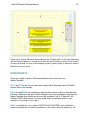
Explanation of the Hot Linked Method for Addition / Remodel Projects
Set up your Addition / Remodel project using two separate PLN files. The first or
Source file functions as the As Built / Existing building model, with the second being the
Destination Addition / Remodel Master file. The Addition / Remodel Master
Destination file will contain both a placed Hotlink Module created from the Source AsBuilt Existing PLN as well as added elements like newly added walls, etc.
The As-Built Existing PLN file that is used to create a Hot Linked Module can
be periodically updated as additional information becomes available throughout the
building survey process. For instance, an ArchiCAD model of the existing field
conditions can be commenced based on initial field measurements, and further refined
later as more detailed information is obtained. It is not uncommon for some building
survey information to be missing or unavailable at the time the remodel concept design
starts to be developed, and this approach allows gradual refinement of the as-built
model while redesign is in process.
By separating the As-Built / Existing PLN from the Addition / Remodel Master PLN, the
As-Built Existing PLN can stand alone as an accurate record of the existing field
conditions, and can easily be up-dated over time. Because the Hot Linked Module
within the Destination Addition / Remodel Master PLN is hot linked to the As-Built /
Existing Source PLN, it will always remain current with that As-Built / Existing PLN.
This contrasts with the method that places all of the existing and addition / remodel
information within one PLN. That approach requires adding many more layers, with a
possible adverse affect on work flow. Further, the accuracy of the original building
survey could be compromised as work on the model progresses.
With the stand alone method as described above, the As Built / Existing Source PLN
can always be independently checked for accuracy and used with a high degree of
confidence in its accuracy. It is not cluttered or combined with additional elements.
In commencing the Source As-Built / Existing PLN, all existing items are simply placed
on their appropriate layers. For instance, an existing exterior wall will be placed on the
A | WALL | EXTERIOR.3D layer, and so on. Modeling the existing conditions continues
to a point when the architect / designer would like to initiate a new model representing
the addition / remodel.
ArchiCAD MasterTemplate Manual
48
Prior to creating the new second file, the user shall select a layer combination (perhaps
* MODULE EXISTING) which shows the completed model for export as the Existing
Module. (Note: the A | DEMOLITION.3D layer can be included in this layer
combination, but this layer must be managed carefully to avoid element interaction
issues relating to demolition items in the new design).
At this point there are two alternate methods for saving as a Hot Linked Module (HLM),
with the preferred as follows: With the As-Built / Existing model visible in plan view,
surround it completely using the multi-story marquee, and select Copy from the Edit
menu. Then in the menu bar select File > Save As, then in the Save As dialog box
under Save As Type, choose 'Module File from Clipboard (*,MOD). Give it a name and
select Save.
The second method uses the same copy steps outlined above, but instead is saved as
follows: in the menu bar select File > External Content > Save Selection As Module.
Here the user needs to make sure the 'Replace Selection with this Hotlinked Module
File' checkbox remains un-checked.
TIP: You may place a polyline around the entire model to help get the Marquee
set up each time very quickly. With the Marquee tool active in multi-story mode
(thick marquee line), Space-Click the polyline, which will trace it with the Magic
Wand. The polyline should be placed on the A | NON-PLOT layer, but be visible
in the MODULE Layer Combination.
The next step is to create a new file that will contain this HLM produced from the AsBuilt / Existing PLN as well as new items representing the addition. Items to be
demolished are placed onto the A | DEMOLITION.3D layer in the As-Built Existing PLN,
and visibility of these demo items are controlled by layer combinations in the new plan.
In the course of the design phase of the project, a wall or portion thereof may
be required to be shown as demolished. In that instance, that wall will be moved from A
| WALL | EXTERIOR.3D onto the A | DEMOLITION.3D layer within the As-Built /
Existing PLN. The As-Built / Existing model will appear unchanged when the A |
DEMOLITION.3D layer is visible. It should be noted that there one needs to go back
and forth periodically between the As-Built / Existing and the Addition / Remodel PLN
files to accomplish these tasks.
Demolition items are controlled within the As-Built / Existing PLN, and are included in
the new PLN via the HLM. Because Demolition items are all on one layer, they are
easily isolated for graphic manipulation within a Demolition Worksheet.
The Demolition drawings are created by copying the elements from each story (after
manually turning on the A | DEMOLITION.3D Layer) and pasting them into a new
Worksheet. While pasting, the entities are automatically exploded into their primitives,
ArchiCAD MasterTemplate Manual
49
but they maintain their respective layers.
Next, isolate the Demolition layer (turn off all other layers, perhaps using the
QuickLayers palette command to Hide Others Layers), then select all the elements in
the Worksheet and modify these primitives graphically to represent demolished items.
Often these are shown with dashed lines and fills; your office standards may be
different.
Wall composites or types used in representing new and existing to remain will be
identical, with the exception of the background fill pen of the core. For the existing to
remain condition, the background fill pen can be either set to transparent or white, while
walls for new construction can have the background fill pen set to a traditional poche
color, like light blue.
For the purposes of auditing or scheduling data, existing to remain, existing to be
demolished and new entities will be accomplished through the use of the entity's ID.
Therefore, entity placement on a particular layer only affects visibility, and is not solely
required for cataloging of information. Again, fewer layers promotes better work flow.
It should be noted that if you wish or have the need to isolate addition or new elements
within the Addition / Remodel Master PLN, that is easily achieved by selecting all new
entities and saving them as a module. The visibility of this new module will be
controlled by one single new layer A | MASTER-MODULE (BLDG. ADDITION).* MOD.
This option gives the user the ability to quickly illustrate the scope of new work
compared to existing from within one file. However this approach creates additional
work that may not be necessary in many cases.
TIP: for the Existing PLN model, where certain conditions require wall trimming, it
is recommended to trim those walls to roofs rather than use Solid Element
Operations in adjusting the wall height. That way Operators do not have to be
included in the exported Module file.
Separately note that new entities within the Addition / Remodel PLN are able to be
modified by Existing Module entities through Solid Element Operations.
ArchiCAD MasterTemplate Manual
50
QUICK GUIDE TO REMODEL PROJECTS
Two PLN files are used, one for the existing building model, and the second that
includes a Hot Linked Module to the first, as well as the new addition elements. The
main purpose of this approach is to significantly reduce the number of layers, thereby
simplifying control and workflow.
Project Setup
1. Create a new project file (PLN) using the ArchiCAD MasterTemplate.
2. Model the existing building.
3. Save a module (MOD) file using the save selection method (multi-story
marquee).
4. Create a second new project file (PLN) using the ArchiCAD MasterTemplate.
5. In the second PLN, create a new layer called * MASTER MODULE | EXISTING.*
MOD.
6. In the second PLN, place the module file created in step 3 above. Use the layer
created in step 5 above as the Master Layer to control visibility of that ‘Existing
Building’ Hot Linked Module.
7. In many cases you may skip step 5 to avoid creating a new layer. Use either the
* MASTER MODULE | BUILDING.*MOD or * MASTER MODULE |
OTHER.*MOD layers, if you are not using them with other HLM files.
Project Development
NEW ITEMS:
•
In the second file, model the addition by adding new elements to the existing Hot
Linked Module.
•
Tip: for new 3D construction elements, alter the background fill pen such that
they stand out when next to existing elements.
DEMO ITEMS:
ArchiCAD MasterTemplate Manual
51
•
Identify elements or portions thereof that need to be demolished as a result of the
new design. (Note: demolition items are manipulated from the Existing PLN).
•
Open the original Existing Building PLN file, place those items to be demolished
on the A | DEMOLITION.3D layer.
•
Tip: when precisely defining alignment of demolition items with new, temporarily
paste new entities from the Addition PLN into the Existing PLN, line up the
entities to be demolished in the Existing PLN, then delete the pasted new items.
•
Overwrite the original module file from the revised Existing Building PLN, which
now includes elements placed onto the A | DEMOLITION.3D layer.
•
Back in the Addition PLN (second file), update the Existing Building MOD.
•
The demolition items are now easily controlled by the A | DEMOLITION.3D. (Tip:
make sure layer combinations are updated so that the demolition layer does not
interact with elements on other layers).
DEMOLITION PLAN:
•
The demolition plan is created in a Worksheet in the Existing Building PLN.
•
Single story marquee and copy the first story that will require a demolition plan.
•
Create a new Independent Worksheet and paste (Note: entities are now
converted into 2D).
•
Make all layers invisible except the A | DEMOLITION.3D layer (Note: this will
isolate all items to be demolished).
•
Change fills and line types in these remaining elements to represent demolition
items per your office standards.
Summary
The Existing Building PLN is used to create Views of the existing and demolition
conditions. Those views are imported into Layout Sheets contained in the Addition PLN
file. The Existing Building file can easily be updated should new information come to
light, or altered with respect to demolition items as the design evolves.
The Master Addition PLN contains a Hot Linked Module to the Existing Building MOD.
Any changes to the Existing Building PLN can be updated in the Master Addition PLN
file, keeping the project current with changes shown in the Existing Building PLN file.
At this point the following representations or Views are available: the existing building, a
ArchiCAD MasterTemplate Manual
52
demolition plan for the existing building, and the remodeled building showing new
elements seamlessly placed onto the existing building.
Finally, should there be an additional requirement to control new elements separately
from existing in the Master Addition PLN, that is easily handled by placing those
addition elements as a new module, controlled by a new layer * A | MASTER-MODULE
(ADDITION).3D. In this case, all combinations of new and existing can be controlled
from within one file, however this is additional work that may not be necessary.
Using this approach, layers are kept to a minimum with new, existing to remain and
demolition items controlled by two module layers. As a result, there is no need to have
individual layers for each existing and new entities with a longer layer list to manage.
Another important concept with this method, a stand-alone file documenting the existing
building model is separately maintained and easily updated. This file is not cluttered
with addition entities, and can easily be checked for accuracy.
Addition remodel projects have often been done using a separate file for the existing
conditions, but commonly that file was unlinked. After commencing documentation of
the field conditions, uncovered or unknown conditions sometimes come to light requiring
altering the existing model. In that case, changes would be required of both the Existing
Building PLN as well as the New PLN. This will not be the case in the method outlined
above as alterations made to the Existing PLN will be reflected in the Master Addition
PLN via the Hot Linked connection.
ArchiCAD MasterTemplate Manual
53
FREQUENTLY ASKED QUESTIONS
Q: Do you break the hotlink in the new addition plan to edit it?
A: No, please do not break the Hot Linked Module in the new Addition file, as that will
defeat the entire purpose of this approach. You will edit the Existing PLN to address the
new conditions created in the Addition PLN.
There is some back and forth which goes on between the Existing PLN and the Addition
PLN. As the addition evolves, you most likely will be required to make adjustments to
the Existing PLN file.
For instance, a portion of a wall (in the Existing PLN) may need to become demolished
based on the new design (being worked on in the Addition PLN). You will need to
accurately know where to cut or slice the existing wall (or element) based on the new
wall (or element) placement.
Locating this exact point in the Existing PLN is achieved by copying the new wall (or
hotspots, lines, roofs, slabs, etc.) from the Addition PLN and pasting them
TEMPORARILY into the Existing PLN. After pasting the new item(s), locate the exact
position of the demo items. Slice those existing items and place them onto the A |
DEMOLITION.3D layer. After this step you delete the temporarily placed elements from
the earlier step described above.
NOW, save the Existing PLN as a Module again AND overwrite the original module file.
THEN update this Hot Linked Module back in the Addition PLN. The updated HLM in
the Addition PLN will correctly show the existing to remain and demolished items as
desired.
TIP: Having both the Addition as well as the Existing PLN files open at the same
time is recommended during the periods of adjustment as in the example noted
above.
Also, in the Existing PLN, your existing plans will display correctly when the A |
DEMOLITION.3D layer is visible (with the exception that there will be residual lines
between where the demo items join the existing to remain items). If that is undesirable,
please draw over these areas with a white pen to hide the joints. The Existing PLN will
exactly represent the existing conditions, even though some of the entities are placed
on the A | DEMOLITION.3D layer.
ArchiCAD MasterTemplate Manual
54
Q: Is the Demo Plan automatically updated as the design changes?
A: The demolition plan on worksheet has been exploded into lines and is no longer
auto updated. It has to be manually updated as you work out which walls/etc get
demo'ed.
Coordination of the demo drawings can be simplified through the use of Virtual Trace. In
the Trace and Reference palette, choose as a reference the Source View (whichever
plan view corresponds to this demo plan). You will then see clearly what changes need
to be made in the demo drawing to keep it consistent with the latest revisions to the
design.
ArchiCAD MasterTemplate Manual
55
LAYER NAMING, USE & MANAGEMENT
The primary goals and the underlying principles for the layer naming convention used in
the Master Template are as follows:
•
Provide a list of manageable size to minimize confusion.
•
Allow for quick and easy sorting and management of layers.
•
Provide meaningful layers, not just a layer for every possible condition.
•
Provide a framework for logical expansion, but initially start with as complete a
general list possible for most projects.
•
Names are explanatory using complete words, not cryptic abbreviations.
•
Intuitive usability; when users are faced with placing an entity onto an unspecified
layer, they will do so intuitively such that those elements will not be misplaced.
•
Provide a visually appealing list that leads the user to logical use.
•
Visual consistency with how fills and materials are now represented in their
respective lists through the utilization of the vertical separator line.
•
The end result is a logical and understandable grouping mechanism to make the
workflow more intuitive, while keeping a minimum of layers.
Background
Graphisoft ships ArchiCAD with an abridged set of layers taken from those provided
from the National CAD System (NCS) and the Uniform Drawing System (UDS). Those
committee-devised layer names were based on two-dimensional drafting systems, and
became the primary means for cataloging and displaying drawing information. The
layer names use alphanumeric coding and cryptic four character abbreviated names,
with (difficult to read) hyphenated sub-sections.
As an example, drawing primitives placed on a layer designated C-SITE-XXXX-YYYY
will be seen on the Site Plan and available for graphic display as a civil engineering
discipline item. As a result, this system requires significantly more layers in
representing subsets of information than necessary in today's BIM environment.
Data management today (for cataloging and auditing purposes) is no longer solely
dependent on layers, but instead uses other means, freeing layers to be used for their
primary purpose of controlling visibility. Data in the BIM environment may now be sorted
ArchiCAD MasterTemplate Manual
56
and collected using ID, element type, and other parameter values.
Displaying information in conjunction with workflow is better handled in the new system,
as layers (although they contain data) now are primarily used for display purposes.
Multiple element types can now appear on the same layer if they are always seen or
hidden at the same times. Further, because doors and windows are now a subset of
walls (children / parent relationship), those past layers are obsolete.
It should be noted however that there are some circumstances where there can be a
requirement to use a more traditional layer naming system. These may be government,
institutional or historic preservation projects, where submissions are required to use
specific standards. As a result, an alternate layer naming system can be provided that
conforms with these special client's requirements.
However, this requirement for use of a standard layer system is the exception and not
the norm for most ArchiCAD users. It must be noted that development of new BIM
standards is underway by the AIA and other groups, and that will further modify the
playing field over the next few years.
In light of the above, we have created a new layer naming (hybrid) system in the
ArchiCAD MasterTemplate, which we believe incorporates the best that those earlier
systems offered. It includes basic preface coding for sorting and grouping purposes,
and categorizes elements in a legible and systematic way.
However our new approach is simpler, more straightforward, and easier to understand
and use. It uses fewer layers, and thereby facilitates easier management. Projects
should only contain the layers necessary to achieve the desired result. In this case, less
is truly more (as long as the system addresses all the project’s conditions).
ArchiCAD MasterTemplate Manual
57
THE ARCHICAD MASTERTEMPLATE LAYER ORGANIZATION
Overall Structure
In developing the ArchiCAD MasterTemplate layering system, a standard hierarchical
categorized system similar to those created by the professional and industry groups
noted above was initially chosen for its sorting capabilities, however it was modified to
better address the requirements of working in the BIM environment.
The logic went as follows: In considering three-dimensional building elements (site
excluded), there are two equally valid approaches; assembly based and tool or surface
plane based. The tool-surface plane based approach seemed to be more intuitive and
thus was selected and developed for this template (e.g. to draw a ceiling slab, select the
slab tool; the layer for this purpose is A | SLAB | CEILING.3D). Also supporting this
concept is that floor slabs on the story above will often act as the ceiling for the floor
below (in residential construction), so the need to have a separate category grouping for
ceilings seemed unnecessary in the context of keeping layer quantities to a minimum.
To keep lists to a minimum, the ArchiCAD MasterTemplate layer combinations lock all
layers that are hidden. In doing so, pop-up palettes only display visible layers, thereby
limiting the list length, making quicker and more efficient review when scanning the list.
TIP: Set the Work Environment preference “Hide Locked Layers in Popup Palettes”.
The overall Layer naming organization uses a hierarchical structure of prefixes at the
first level, then tools (elements), surfaces and/or conditions for second level naming,
followed by subset conditions if necessary, then finally layer extensions. Each subset
name is partitioned using a vertical “pipe” separator { | }. Sorting and managing this
layer list is very simple, and is accomplished using the categories as the list headings,
including the 'Funnel' filter for extensions. The vertical separator lines provide visual
assistance when scanning this list, and enhance the process as a result.
The actual list of layers in the ArchiCAD MasterTemplate was developed based on
actual testing with real projects. Testing occurred primarily using single and multi-family
residential projects, however some commercial testing has also been done, and the
layers still provide complete functionality for these projects as well.
The layers provided comprise a balanced amount appropriate and necessary for any
small to mid size project. Unneeded layers may be purged, and alternate layers may
easily be added. It should be noted however that the layer combinations which come
with the MasterTemplate are set to use those layers included, and adding new layers
will require manual updating of each combination one at a time.
ArchiCAD MasterTemplate Manual
58
Layer Names Prefixes Table
Layer name prefixes are used for categorizing and are as follows:
PREFIX SORTING GROUP
REMARKS
A
Architectural
C
Civil Engineering
S
Structural Engineering
L
Landscape
M
Mechanical
E
Electrical
P
Plumbing
U
Drawings
See extension table below.
Y
Special Elements
See extension table below.
Z
Trash / Recycling & Warnings
ZZ
Detailer Items
*A
Modules
ArchiCAD MasterTemplate Manual
59
Layer Name Extension Table
Layer name extensions are used for grouping as well as sorting purposes and are as
follows:
EXT
LAYER TYPE
TYPICALLY PLACED ITEMS
3D
Building Model Elements, common
items that typically appear in most
drawings.
Walls, Slabs, Roofs, Stairs, Cabinets,
Moldings, Columns, Beams and 3D
Objects.
2D
Building Info Elements, semi-common Dimensions (if need to separately
items that appear in some drawings, control), Room Names, Drafting Fills,
which materially add to or describe
Part Symbols and Zones.
the building.
MARK
Reference Elements, semi-common
items that appear in some drawings.
Section, Elevation, Detail & Interior
Elevation Marks as well as break lines.
UNIQ
Drawing Elements, unique items that
appear in one individual drawing at a
time, which annotate and describe.
These items can be 2D & 3D and
describe the building.
Dimensions (if no need to separately
control), Labels, Notes, etc. In general,
any elements specific to, and limited to,
a particular drawing.
Y (prefix)
MOD
Special Elements, special items that Solid Element Operators (Visible or
may or may not be visible, but are
Hidden), Explanatory Text and
used to generate the model, data or a Prompts and Model Part Extras.
special view or appearance. Can be
2D or 3D extensions.
Control Elements, allows for separate Used to control the visibility of legends.
control of modules.
Also as an example, individual units
within an apartment or hotel type
project.
DETAILER Detailer Elements, allows for the
Refer to Karl’s explanation.
incorporation of that detailing system.
ArchiCAD MasterTemplate Manual
Z
60
Trash / Recycle & Warning Elements, Any elements can be placed onto the
allows for a depository for temporary trash layer.
holding of elements prior to
permanent removal from the project.
EXIST’G
Existing Elements, filter & organize
these elements that otherwise would
be a part of 2D & 3D extensions.
Self explanatory. Delete these layers
for new construction or leave unused.
These layers can be omitted entirely in
remodel projects when the module
approach is used.
DEMO
Demo Elements, filter & organize
these elements that otherwise would
be a part of 2D & 3D extensions.
Self explanatory. Delete these layers
for new construction or leave unused.
ArchiCAD MasterTemplate Manual
61
Additional Concepts and Items of Note
•
The use of unique 'U' layers allows for all two-dimensional descriptive information
relevant to a specific drawing to exist on one layer. Entities that are required to
be isolated and/or seen for multiple drawings shall not be placed on these layers.
For instance, room names would not be placed on any of these layers because
they are a common entity used in many combinations. Dimensions may be
placed onto a 'U' layer if there is no requirement to isolate them. (In some ways,
dimensions function the same as annotations, describing the building model.)
In conclusion, anything that describes or modifies a particular drawing may be
placed onto a UNIQ. layer, i.e. dimensions, descriptive text, keynotes, labels, fills,
or other primitives which are unique to that drawing. Elements on a specific U
layer are shown for the corresponding drawing, and are hidden for all other views
and drawings.
•
All modeling elements have the 3D layer name extension, which is useful when
sorting and filtering the list. Most of the 3D layers are visible for creating and
working with the building model or site model.
•
Suggested working method relating to understanding Layers: Print out a list of all
layers and combinations for quick reference. Use OPTIONS > ATTRIBUTE
MANAGER, select the Layers tab, then print to a TXT file, open in Excel, sort and
print. You may want to separately add the layer extensions in another column as
they are not delimited in this process.
•
When setting up an addition / remodel project, please refer to that section of this
document for a complete explanation. However, the following comments are
appropriate here:
•
Layers with the file extension EXISTG are generally not necessary for
differentiating between new, existing to remain and existing to be
demolished elements. Those elements can alternatively be controlled
through ID management as well as graphic representation, and further
through the use of modules. New walls can use the same composite wall
structure as existing walls, but have the background fill pen set
(overridden) to a traditional blue poche, while existing walls can have their
background fill pens set to white or transparent.
This approach is based on a two file system described earlier above,
where one PLN contains the Existing conditions including demolition
items, and the second PLN contains a Hot Linked Module to the Existing
plan as well as added New elements. Items to be removed shall be
placed onto the Demolition Layer in the Existing PLN, which is typically
hidden and set with a different layer intersection value.
ArchiCAD MasterTemplate Manual
62
Demolition plans are easily created by pasting a copy of the floor plan into
a worksheet, then by switching the module layer off, the demolition layer
will be isolated for manipulation of elements. Line types and fills are easily
modified to represent demolished items.
•
BIM layering is basically organized into two major groups; modeling and
annotation (with annotations all being placed on the U | DRAWING layers).
There appears to be no need in a BIM system to segregate 3D
assemblies/parts by layer for auditing purposes as that is more properly handled
through ID management, and thereby reduces the need for dedicated layers.
•
If an imported DWG file layer structure must be preserved, a layer extension of
DWG is appropriate to add (one can also add a sorting mark like a tilde to the
beginning of each layer for additional grouping purposes).
Sometimes users get confused about the relationship between stories, layers, elevation
levels (z-heights) and the stacking order of elements. Each system is independent of
the other, although they all have some bearing on the visibility of elements. Layers do
not actually stack on top of each other or correspond to display order, and heights are
not used to determine which elements appear on top graphically.
Elements are shown on a plan if they are on a visible layer and the current story is their
home story (which is usually the one they were drawn or created on). Elements based
on a different home story may be visible if their settings allow it. This happens
commonly for multi-story walls if their story visibility set to Automatic, and their height
places them within in the current story’s height range. Slabs or roofs may also be seen if
their parameter is set to show on the story (or stories) above or below. and some
objects and elements such as stairs may also show on multiple stories.
ArchiCAD’s built-in display order rules determines which element stacks “in front” or
“behind” another element. For example, lines and text generally float in front of walls
and fills so that they are not obscured. These display rules are based on element types,
not on heights, so manual intervention may be necessary for certain cases such as
when chairs are showing graphically in front of the table that they should go behind
(underneath). Use the Edit menu > Display Order submenu to override these rules for
specific cases, changing which elements are in front of overlapping ones.
ArchiCAD MasterTemplate Manual
63
A Place for Everything - Example List of Where Elements Belong
LAYER
ELEMENT
A | MOLDINGS | LOW
Lintels over
openings.
REMARKS
A | MOLDINGS | LOW -or- A Wall Caps.
| WALL | ACCESSORIES
Y | SPECIAL | MODELING- Filled in areas like
Elements that are visible in 3D, Section
ELEMENTS (VISIBLE)
walls above roofs at & Elevation but not in any plan view.
dormers; soil in pots
or raised planters.
Y | SPECIAL | MODELING- Solid Element
Hidden in most views, but turned on
ELEMENTS (INVISIBLE)
Operators or
while creating or editing these elements
interacting elements. to create effects on other (visible) model
elements.
A | WALL | ACCESSORIES Applied skins and
wall treatments;
Downspouts
Like those from Cadimage; stand-alone
downspouts like with leader head.
A | ROOF | FRAMING
Manually placed or automatically
created using RoofMaker.
Roof rafters
A | ROOF | ACCESSORIES Applied roof surface Roof surfacing like those from
(RAFTER TAILS +
skin; gutters
Cadimage; use for rafter tails when
SURFACER)
modeled separately from structural
rafters
L | LANDSCAPE | 3D
PLANTS
Plants, Terra Cotta
Pots
Seen in 3D exterior views and on
Landscape Plan.
ArchiCAD MasterTemplate Manual
64
U | UNIQUE | PLAN +
SECTION +
ELEVATION.UNIQ
Building Dimensions For annotations only seen on Floor
(plus other
Plan, but not other Plan drawings; this
annotation)
layer may be used for any 2D work
placed on sections or elevations
U | UNIQUE | PLAN |
SITE.UNIQ
Site Dimensions
(plus other
annotation)
For annotations including dimensions
only seen on the Site Plan.
A | DIMENSIONS
Common
Dimensions
Those which repeat between multiple
drawings.
C | SLAB - ROOF | SITE
HARDSCAPE (PATHS DRIVES)
Paths, Ramps,
Driveways
Roadwork goes on C | SITE | STREETS
+ CURBS + GUTTERS; allows isolation
of nearby and distant civil model
elements.
ArchiCAD MasterTemplate Manual
65
Layer Combinations Naming and Use within the ArchiCAD
MasterTemplate
In contrast to keeping the Layers list to a minimum, it seemed correct to expand the
layer combination list to cover the broad range of conditions, even if redundant
combinations occur as a result. In that regard, Layer combinations were provided for
each drawing type possible. That includes both presentation as well as contract
document drawings.
Layer combinations generally correspond to Views, and have been set to show the
appropriate elements for the creation of construction drawings.
In addition to layer combinations for drawings, additional combinations are also
provided for other non-drawing conditions and processes, such as Modeling, Detailing,
Layouting and * Special.
Layers that are hidden in any particular Layer Combinations are also set to be locked.
This shortens the layer list in pop-up palettes, thereby enhancing workflow.
Updating layer combinations will be necessary should new layers be added or existing
layers be modified. The procedure for this is outlined below.
Procedure for updating layer combinations
If the addition of a new layer is required, open the Layer Settings Dialog Box. Select the
added Layer on the right side column, and start at the top of the Layer Combination list
on the left side.
For each layer combination, inspect and set the visibility, mode, interaction and locking
attributes one at a time. Go through each layer combination all the way to the bottom.
After all have been set for the new layer, you may move on to the next new layer on the
right side (if any), and repeat the process for each layer combination. When you have
completed this for all new layers, click OK and exit the Layer Settings dialog box.
ArchiCAD MasterTemplate Manual
Conceptual Layer Combination Table
The following table illustrates the visibility of different elements as set within layer
combinations.
Insert Layer | Layer Combinations Matrix here.
66
ArchiCAD MasterTemplate Manual
67
MODEL VIEW OPTIONS NAMING, USE &
MANAGEMENT
Model View Options are one of the seven named settings that make up a View in the
View Map. And although all seven settings are important in controlling the expected
outcome of a View, the two most critical are Layer Combination as well as the Model
View Option settings, with the latter most often being misused. The importance of this
setting is often overlooked and as a result, can be the cause of great confusion. That
being said, we set out to simplify use of this setting as much as possible by providing an
intuitive naming scheme.
In the ArchiCAD MasterTemplate, names for Model View Options are literal and based
on the type of View they are associated with. So for instance, a CONDOC Floor Plan
View will receive a CONDOC | FLOOR PLAN Model View Option as well as a CONDOC
| FLOOR PLAN Layer Combination. This straight forward approach uses the principle
of matching names, avoiding cryptic names that invariably lead to confusion and
possible errors. Note: this is true for most Views, but may vary slightly depending on
certain Views.
In MasterTemplate, Views, Layer Combinations and Model View Option names closely
match each other. Some Model View Option are redundant in that two different MVO
names use exactly the same settings, which makes for a slightly longer list of
combinations. However, this approach facilitates a greater ease of establishing View
settings by using matching setting names, thereby removing guesswork and improving
workflow.
Of note though is that we have preset Views using the above mentioned naming
convention. So for most of your work MVO choices should not require much attention,
however there will be times when custom adjustment may be required. For those times
our MVO naming system will greatly assist in workflow ease.
If you should need a new MVO combination custom to your specific need, please create
that MVO in accordance with the description found in the ArchiCAD User's Manual.
ArchiCAD MasterTemplate Manual
68
PROJECT MAP STRUCTURE |
FEATURES
Every ArchiCAD project file has a Project Map with the following sections:
Everything drawn in the project may be found somewhere in this Project Map (or in the
Layout Book where Drawings are placed onto Layout sheets). These sections or folders
contain “viewpoints” for entering, managing or accessing information such as 3D model
elements, 2D annotation, or reports such as schedules, indexes or lists.
Let’s take a tour of all the viewpoints already set up in Project Map in a MasterTemplate
file. Later, we’ll study the View Map, where these viewpoints are codified into specific
“viewing styles” (technically, the View Settings), then we’ll look at the Layout Book
where the Views are placed as Drawings on Layout sheets.
STORIES
In MasterTemplate, we start the project with four stories: the FIRST FLOOR (USA) /
GROUND FLOOR (International); the next story up - SECOND FLOOR (USA) / FIRST
FLOOR (International); another story up for the TOP PLATE (roof); and a bottom story
for the FOUNDATION. You will need to adjust the story to story heights for your project,
and may add or remove stories and rename them if necessary.
ArchiCAD MasterTemplate Manual
69
SECTIONS
There are four pre-set Sections that are drawn and placed into a “holding area” off to
the right side of the central area. (See the screen capture on the next page.) It is
intended that you move and stretch these into position (rotating if appropriate) at some
point after you have created your building shell.
Three of these are set for construction documentation (CD01 SECT A, CD02 SECT B
and CD03 SECT C), and one is intended for presentation usage (P01 SECT A) with
parameters set for creating shaded views with shadows cast. You will most likely create
additional Sections during the project lifecycle, and may eye-drop one of the existing
ones to reuse the settings if you wish (changing the ID and Name, of course).
ELEVATIONS
There are 8 Elevation Markers pre-drawn, 4 for construction documents (CD series:
EAST, NORTH, SOUTH and WEST) and 4 for presentations (P series). These are
arranged around the central area of the original base slabs, and will probably need to be
adjusted depending on the size of your building. If the orientation of your project does
not have North at the top of the screen, feel free to rename them.
TIP: To correspond the pre-drawn Elevation markers with a different cardinal
direction, it is easier to select all of the Elevations at once, and rotate them into
the proper position. That will change all of them in a single step to the proper
orientations, after which you can move and/or stretch them as needed.
VIEWING AND ADJUSTING SECTION AND ELEVATION
MARKERS
To see all of these pre-set markers and adjust them, switch to the View Map and
double-click the Canvas Limits view. That will turn on the layers for Section and
Elevation markers and zoom out to fit the entire model onscreen. You will notice that the
Construction Document sections and elevations are shown with black marker heads,
while the Presentation ones are set with red markers. The Elevation markers are set in
pairs for each cardinal direction, one for CD and one for presentation.
ArchiCAD MasterTemplate Manual
70
There is one Interior Elevation group placed in the “holding area” on the right side along
with the Section Markers. You may move this into position within a room of your model,
or simply eye-drop it to pick up the settings as part of getting ready to draw your Interior
Elevations for each room.
WORKSHEETS
There are a large number of Worksheets already set up with content in
MasterTemplate:
DT-01 and DT-02 are for your use when creating Detail drawings (see the Detailer
section later in this manual).
EX-01 through EX-05 are explanatory materials that may be studied to see alternate
Pensets, understand how each Penset changes colors and lineweights, learn how the
MasterTemplate layer system works and view a subset of the U.S. National CAD
Standard (NCS) layer names. You may delete these Worksheets (either in your
template, or in a project) if you wish.
KN-01 is available for you to place FLOOR PLAN KEYNOTES if you would like to
create a standard set of notes for placement on the Layout sheet for each story. An
ArchiCAD MasterTemplate Manual
71
alternative is to create keynotes separately for each story, perhaps directly added to the
Layout sheet. Both systems are supported in MasterTemplate.
LG-01 through LG-04 are set up for various Interactive Legends of Visual Favorites, the
arrays of common elements for quick reference and eye-dropping settings. See the
Interactive Legends section of this manual for more information on usage.
PLN-01 through PLN-05 are available for your use to draw or import DWG or PDF files
for site surveys, site plans, site demo plans, grading and drainage and utility plans.
PLN-06 is set up as a “scratch pad” for sketches as well as temporary or long-term
storage of miscellaneous reference drawings; you can create additional worksheets of
course for this purpose as well.
You may also create your own Worksheets for any 2D drawing purpose, including Wall
Sections, Enlarged Plans, Demo Plans, reference materials, temporary drawings, and
backgrounds for use as trace references, etc.
DETAILS
In MasterTemplate, there are three Details initially set up. D-00 DETAIL CREATION is
intended to be used for creating new detail drawings, in conjunction with two
worksheets referenced with Virtual Trace as a background: DT-02 DETAILER
TEMPLATE is used for consistent framing and placement within a layout grid system,
and DT-01 DETAILING LIBRARY PARTS provides quick access to common 2D
detailing component parts.
In addition there are two example detail drawings: EX-01 is a foundation detail set as a
source drawing, and EX-02 is an example of a linked detail window. Please see the
Detailer section of this manual for further explanation of how we recommend using the
template to speed the production and organization of detail drawings.
3D DOCUMENTS
There are five 3D LEGENDS, which show 3D views of a number of the “Quick Rooms”
in the Interactive Legends. These are set for manual updating, so they will come up
instantly when activated, and give very quick access to the elements in these pre-set
room arrangements. You may eye-drop elements in these rooms from the 3D
Document, then return to your design and place them into your model. Please refer to
the manual section on Interactive Legends for more instructions.
In addition, there is one example drawing: AD-01 ANNOTATED 3D DOCUMENT. This
ArchiCAD MasterTemplate Manual
72
shows a cutaway of a sample model with dimensioning and annotation. You may delete
this example from the template and/or individual projects if you wish.
3D
There are several pre-placed cameras that show up in the 3D section of the Project
Map. The Path 00 STREET PERSPECTIVE has one camera that is used as the basis
of one of the Views in the View Map. It may be adjusted or replaced as desired, and you
may add other cameras to this path.
Path 01 NONE may be used as a quick way to hide cameras
from the floor plan. In the Camera/VR Settings dialog box, you
may switch from 00 STREET PERSPECTIVE (the default
Path) to other Paths using the popup menu; if you pick the 01
NONE path, there are no cameras and therefore the cameras
will disappear from view.
Path 02 KEYFRAME FLY AROUND has four cameras
arranged equidistant from the center of the initial modeling
area. You may use these cameras as the basis for easy
generation of an animation that smoothly flies around the
model in a circle. If your model is a different size, placement or
proportion, you may select these four cameras and move them
to a better position.
TIP: To make the circle of cameras larger or smaller very easily, select all four
cameras, and use the Edit menu > Reshape > Resize. The Resize command will
not actually make the cameras a different size (they have no physical dimension),
but it will make their configuration have a new radius (the target point will remain
centered as the cameras move further or closer from that point).
SCHEDULES
There are a large number of Element Schedules in MasterTemplate. Please review
these so that you are familiar with the various options. Some include picture images of
the elements, while others are purely tabular.
It is expected that you will customize these and perhaps add to them. If you customize
or add to them in your actual template file, all new projects will inherit the revisions and
additions. If you modify or add to the schedules in a particular project, it will not affect
other project files. However, you may use the Schedule > Scheme Settings > Export…
button to save an XML file with the schedule Scheme, and later use the Import… button
ArchiCAD MasterTemplate Manual
73
to bring in that XML Scheme into another project or your template file.
We have not created any new Component Schedules (these generate quantity takeoffs), so the ones you see in the Project Map are those created by Graphisoft. If you
wish to create new ones, you may add them to your template or any project file.
PROJECT INDEXES
There are a large variety of Project Indexes in MasterTemplate. Many of these are
simply variations with different Index Settings Criteria, so that they include only specific
Subsets. Some of these will appear empty until you create Layouts which match the
Subset Criteria.
There are some variations in formatting of the Indexes as well, so you may consider
these as examples for you to review and choose whichever you find most appealing. Of
course, you may modify, delete or add to these Indexes at any time.
There are two special purpose Project Indexes, the Drawing List and the View List.
The Drawing List is a Project Index that shows a summary of all Drawings placed on all
the Layout sheets, including quite a bit of information that may help in project
management. For example, you can see the Pen Set for each Drawing, the Scale, the
Source View, the Last Update, and the Layout that this Drawing is placed onto. Since
Project Indexes are bi-directionally associated with the Drawings and Layouts, you may
edit the names, scale, pen set etc. right from the Drawing List.
The View List is another special Project Index that shows all the Views defined in the
project. You may use it in a similar way to the Drawing List, in that it shows a lot of
information for each View and you can edit the View Settings directly from within the
View List window.
LISTS
The Lists in the Project Map provide a sophisticated system for generating raw or
formatted quantity reports from your model. MasterTemplate has not added anything to
the Lists that are provided by Graphisoft.
Feel free to study these various Element, Component and Zone lists to see if any of
them provide information you find useful. For information on how to customize and
create your own Lists, please consult the ArchiCAD Reference Manual or your local
reseller or ArchiCAD specialist. Bobrow Consulting Group is also available on a
ArchiCAD MasterTemplate Manual
74
consulting basis if you wish to delve deeper into quantity analysis of your projects.
INFO
Project Notes is an editable text area that can be used for any purpose. In the
MasterTemplate file, we have placed notes from one of the revisions to the template
itself. This is an example of how you can add notes for later reference.
Each time you open the Project Notes, ArchiCAD will paste in a time-stamp as a
convenience; this may be edited or deleted at will.
The Report will show information about the most recent generation of certain Views,
including 3D, Sections, Elevations, etc. There are options for how much detail will be
included in this Report window, which are set in the Options menu > Work Environment
> Imaging and Calculation.
HELP
The entries in the Help section of the Project Map are built-in to the program, and
include About, Help and a link to the Graphisoft website.
ArchiCAD MasterTemplate Manual
75
VIEW MAP STRUCTURE | FEATURES
MAIN CATEGORIES & GENERAL NOTES
In the View Map, MasterTemplate has set up five main categories to organize your
information and workflow:
1. Imported Reference Documents (Worksheets) - These are empty folders for you to
place Views of some of your Worksheets, typically of imported reference materials.
2. Modeling – Design – Legends - This is where you will spend much of your time at the
beginning while you design, and will continue to refer to for access to the Interactive
Legends of Visual Favorites.
3. Construction Document Views - Once you have created your basic model and started
annotating it, you’ll use these Views to refine and generate each of your Construction
Document drawings.
4. Presentation Document Views - These Views are variations of the construction
documents which are intended for use as presentations: Colored Elevations with
shading and shadow, Furniture Plans, and others.
5. Trash Recycle Bin - You may place any Views or folders into the recycle bin to “get
them out of the way”, then later decide whether you want to restore or delete them.
Note that some of the Views have saved Zooms (specific locations of the plan or other
viewpoint that will be shown when the View is activated) and others have “no zoom” (the
View Settings have the checkbox set to “Ignore zoom when opening this view.” In
general, if the View is one for working on the model or a specific drawing, we often set
“no zoom” so that when activating that View one returns to the last place one was
working or looking at.
On the other hand, some Views are specifically designed to take you to a location, and
they record the zoom (and in 3D views, the angle or camera position). You may adjust
these Views to match a new position by right-clicking the View in the View Map and
ArchiCAD MasterTemplate Manual
76
choosing View Settings, and clicking the “Get Current Window’s Settings” button near
the top of the dialog box. (NOTE: To change a 3D Perspective camera position, one
uses a different command, as described in that section below.)
IMPORTED REFERENCE DOCUMENTS (WORKSHEETS)
We have set up three empty folders for you to use to organize reference materials:
•
Consultant Imports (DWG Import)
•
Design Sketches (PDF Imports)
•
Web Downloads (PDF & DWG)
You may create new Independent Worksheets for these reference drawings, and then
create Views of each Worksheet to place into the appropriate folder. This system may
be modified or extended as desired.
MODELING - DESIGN - LEGENDS
MODEL / DESIGN VIEWS
The MODEL / DESIGN VIEWS folder is where you will spend much of your time in the
beginning of your project development. Here is a description of each View in that folder,
along with its intended use:
•
CANVAS LIMITS - Activate this View when you want to see the Elevation and
Section Markers as well as your Site and the building shell. You’ll use this when
you need to adjust the placement of the Elevation markers, or to move other
elements into position. This View automatically jumps to Fit in Window, so it will
always zoom out to show all visible elements.
•
PRELIMINARY DESIGN - This View is what you will use when first laying out
your building model on the site. It has most of the Layers turned on, with certain
exceptions. For example, markers are turned off to avoid having to be concerned
about them until you have built up your basic model; layers that will be seen only
on specific drawings (e.g. Electrical Plan, Ceiling Plan, etc.) are also not shown
at this time.
At a certain point, this View will start getting unwieldy as you assemble more of
the model and annotation and it becomes less legible; at that point you should
consider switching to dedicated Modeling or Construction Document Views.
ArchiCAD MasterTemplate Manual
77
This View does not have a Zoom attached (the checkbox is set to “Ignore zoom
when opening this view”), so whenever you activate it, you’ll be back at the same
place you last were working. This facilitates jumping back and forth to the
Interactive Legends (see next section).
This View is set for the ground floor. When working on a multi-story building, you
may use this View to return (from the Interactive Legends, the 3D Window or an
Elevation, etc.) to the floor plan, then jump to the desired story using keyboard
shortcuts or any other standard ArchiCAD method. However, feel free to create
additional variations of this View for other stories if desired - simply activate this
View, then go to the other story, and use the Save Current View button at the
bottom of the View Map.
•
INTERACTIVE LEGEND WORKSHEET - This is a very special View that you
will likely use frequently. Activate this View to see the main groups of visual
favorites for eye-dropping to pick up settings. It does not have a saved Zoom, so
when you double-click this View you will return to the last place you were looking
in this Worksheet. There are pre-saved Zooms available in the navigation area at
the bottom left of this Worksheet window - use the little popup menu just to the
right of the scale and percentage displays. These Zooms will jump you to
different sections of the Interactive Legends.
The Interactive Legends are organized to mimic the construction process as it
relates to the steps in building an ArchiCAD computer model. They are therefore
organized as follows: First assembled are slabs, walls & roofs. Second, doors &
windows are placed. Third, plumbing fixtures, appliances & other mechanical
items are placed. Fourth, electrical systems & lighting are placed.
You may find it convenient to resize and move this Worksheet to a second
monitor screen, so that you can refer to the Legends without actually clicking on
the View and having this window come up in front of your plan. That way you can
go back and forth and keep both the plan and the legends in view.
ADVANCED NOTE: This Worksheet is prepared in a very special way to allow
Walls, Windows, Doors, Roofs, Slabs and other 3D elements to be visible and
active for use with the eye-dropper. (Normally, Worksheets only contain 2D
elements.) If you use the Fit in Window zoom, you will see the Legends actually
are a Hotlinked Module placed in a corner of the first floor of the Plan, that use a
special Master Layer to control visibility. In the Worksheet, you are seeing this
HLM on the Plan using Virtual Trace. For more information on how this is set up,
please see the section on customizing the Interactive Legends.
•
3D AXO VIEW & 3D PERSPECTIVE VIEW - These are saved 3D Views that will
take you to the 3D window to look at your project model. The Axo view will
automatically Fit in Window, so you will usually be able to instantly see the entire
model. The Perspective view is set to look from “street level” towards the original
ArchiCAD MasterTemplate Manual
78
canvas working area, and may need adjustment depending on how you place
your model.
You may adjust either of these Views to suit your needs, and of course navigate
around the 3D window freely. If you’d like to change the Axo view, simply activate
it, then move to your new viewing angle or position, and then right-click the View
and choose View Settings. In the dialog box click the button at the top “Get
Current Window’s Settings” then click OK.
For the Perspective view, since it was created from a Camera placed on the floor
plan and it is “attached” to that Camera, you need to do this somewhat
differently. After moving to the new position or angle, right-click on the View in
the View Map and select “Modify this Camera to Current view.”
•
SITE DESIGN (LAND & HARDSCAPING) - This View activates the Layer
Combination and Model View Option appropriate for work on site design. You’ll
see the building shell along with the site, as well as the CD section markers.
•
BLDG. DESIGN (SECT-ELEV) - This View uses the same layers as the Site
Design View as you work on the building model, but changes the Model View
Options to start drafting the construction documents, with Mark-ups shown.
•
INTERIOR DESIGN - This View switches to a Furniture Plan layer combination,
which will show the building walls along with fixtures and furniture. It is suitable
for basic interior planning, design and fit-out of the model.
INTERACTIVE LEGENDS (FAVORITES)
The INTERACTIVE LEGENDS (FAVORITES) folder contains several subfolders for
access to the Interactive Legends of Visual Favorites.
•
The LEGENDS | WORKSHEET folder contains multiple views with saved Zooms
of the Legends Worksheet referred to earlier in this section. We have retained
this folder and these Views as an alternative to the Zoom popup in the bottom left
of the Worksheet window; however, they are generally not needed and may be
deleted if desired.
•
The LEGENDS | PLAN folder gives direct access to the Interactive Legends,
with multiple saved Zooms. Direct access is generally only needed when revising
or reworking the Legends themselves, so you may not need to use this folder at
all. However, be careful and DO NOT DELETE this folder or the View called
LEGEND 3D | ALL, since it is referred to by the INTERACTIVE LEGEND
WORKSHEET as a Virtual Trace Reference. Please leave this folder alone
unless you are confident you fully understand the setup of the Interactive
Legends and need to make changes.
ArchiCAD MasterTemplate Manual
79
•
The 2D LEGENDS (DETAILING | SECTIONS | ELEVATIONS) folder contains
Views for several different Worksheets with Interactive Legends specifically for
use with Sections, Elevations and Detailing. Feel free to open and explore and
refine the contents, but do not delete these Views as several of them are used as
Virtual Trace References for Section, Elevation or Detail windows.
•
LEGENDS | 3D VIEWS contains many views of the Interactive Legends in 3D.
You may use these as an alternative to the plan view of these Legends. This may
help to view and pick appropriate elements for eye-dropping settings. You’ll also
get a better understanding of the preset Quick Rooms when you study them in
3D.
These Views will bring up the 3D Window with the Layer Combination set to
reveal the Interactive Legends (normally these Legends are turned off while you
work on the model), and have an active clipping marquee so that they only focus
on one section of the Legends or Quick Rooms. You may rotate around to see
the elements from different angles.
When you want to return to your model, perhaps after eye-dropping an element,
you will need to use one of the Views rather than a shortcut such as the F2 key,
since the Layer Combination is reset by these Views. When you double-click on
the PRELIMINARY DESIGN or any other working View, you will set the Layer
Combination back the way you need to continue work.
•
LEGENDS | 3D DOCUMENTS contains Views of the saved 3D Documents
created from several of the Interactive Legend Quick Rooms. As 3D Documents,
they are locked into a single orientation, and cannot be viewed from another
angle. Their shaded display is different than the OpenGL 3D window. You can
eye-drop elements in this window as well, and return to your working view
quickly.
These 3D DOCUMENTS may be enhanced with text, labels and dimensions, but
we have not done this in the standard MasterTemplate. Feel free to add more
information to these document windows if you find it useful for your purposes.
3D PROJECTED VIEWS
The 3D PROJECTED VIEWS folder contains two subfolders, one for active use in the
3D Window, the other for creating Photo Renderings.
•
OPEN GL VIEWS (3D WINDOW) is a folder with many saved 3D Views. These
illustrate different viewing conditions that you may find instructive. Some of them
activate Layer Combinations that invoke “special effects” or different viewing
styles such as Hidden Line.
ArchiCAD MasterTemplate Manual
80
For example, SEE THROUGH WALLS uses a layer combination that has the
Wall layers set as a wireframe. SEE THROUGH ROOFS is similar except that
the walls are normal but the roofs are wireframe. HIDDEN LINE AXO creates a
line-drawing by changing the 3D window settings (check out what’s been
changed in the View menu > 3D View Mode > 3D Window Settings).
The CUT-AWAY AXO has a stored Marquee cutaway; this is created by going to
3D with a Marquee drawn on the plan, and selecting Show Selection/Marquee in
3D; a View like this can then be Saved and the Marquee cutaway is
remembered.
Please explore these to understand how you might use them during your design
and presentation process. You may want to refer to the Sample Project in order
to see the effects in context, since some of the saved angles and Marquees may
not show properly in your own model. Once you know what these Views can do,
feel free to adjust, remove or add to them as desired.
After you clear out any Views you no longer need, this folder is a convenient
place to story your own 3D Views. You may use this for your own quick access to
part of the model, or to quickly bring up views of the model for presenting to your
clients.
•
PHOTO RENDERINGS (PRESENTATION) is a folder with two saved Views.
One of them is set to generate a Lightworks rendering, the other a Sketch
rendering. Experiment with this at any time to see what they generate.
You may revise or add to these Views, and also may place any of them onto a
Layout sheet. When you Update the Layout sheet(s), the View(s) will be
regenerated with the current state of the model. This can be an excellent way to
enhance a set of drawings, with the images “guaranteed” to be consistent with
the construction documents.
MODULE VIEWS (FOR EXPORT)
This folder has a special purpose, and is supplied with only one View although you
could add others if needed. This View activates a Layer Combination that is set up for
exporting the building model as a Hotlinked Module from one project file to another. This
layer combination makes visible most or all of the 3D modeling elements, and turns off
the markers so that Sections and Elevations are not included in the export.
A lengthy explanation of how this concept is used for remodels and additions is included
in that section earlier in this manual. This approach can also be used when Hotlinking
one or more buildings into a Site Model PLN file, or any time that one building model
needs to be Hotlinked into another ArchiCAD project.
ArchiCAD MasterTemplate Manual
81
Basically, after invoking this View, zoom out to see the whole model, then draw a multistory (heavy border) Marquee around everything you wish to include. Use the File menu
> External Content > Save Selection as Module… command, and save the visible
model elements (this approach will not include anything on hidden layers) as a MOD
file. In general, uncheck the “Replace selection with this hotlinked module file” so that
the elements remain editable within this file.
In your destination file, you may use the File menu > External Content > Place Hotlinked
Module… command to bring in the MOD file.
CONSTRUCTION DOCUMENT VIEWS
This section of the View Map is used to prepare your actual working drawings. It
includes a very extensive collection of Clone Folders for most of the construction
documents, along with a few normal folders with miscellaneous additional Views.
Clone Folders
Clone Folders are special organizing tools available in the View Map that create
“viewing styles” for sections of the Project Map. Each Clone Folder points to and
remains associated with a specific folder or category of the Project Map, such as
Stories, Sections, Elevations, Details, etc. The Clone Folder automatically includes
Views for EACH viewpoint in that Project Map category, and will expand as more are
added.
A brief example will make this idea clearer to those of you who are not familiar with this
part of the ArchiCAD working environment. When we generate a Section, it’s important
to have certain layers turned on so we see the appropriate parts of the model. The
walls, roof, slabs and fixtures are visible, but generally the movable furniture is not. This
is of course controlled by the Layer Combination for the Section View. In addition, other
conventions are used for all Sections in a particular project - they generally use the
same scale, Model View Option, dimensioning style, etc. When you put all of these
together in the View Settings for a Section, you may consider or describe this as a
“viewing style”.
If you create a Clone Folder for Sections, and set this viewing style for that folder, then
your setup work is simplified. Each time you draw a new Section, a View is created in
that Clone Folder with the specified viewing style (technically, the same View Settings).
You don’t have to create the View manually, it’s done for you, and it’s guaranteed to be
consistent with the other Section Views.
ArchiCAD MasterTemplate Manual
82
Now that we have that example in mind, let’s take a
look at the View Map section for CONSTRUCTION
DOCUMENT VIEWS, as seen in the screen
capture on the left.
Notice that GENERAL INFO and the folders
directly below look like simple file folders, while the
FLOOR PLANS, SECTIONS and others in the
middle section have very different icons.
The GENERAL INFO folder is a “normal” one, and
one can add subfolders or individual Views into
such folders as desired.
The various folders inside the FLOOR PLAN
VIEWS (CLONE) are all Clone Folders, and they
each record a “viewing style” for that type of
document. For example, FLOOR PLANS ¼” (in the
International Template, FLOOR PLANS 1:50) is
used for many projects as the primary floor plan
document. It uses a certain layer combination, the
named scale, and MVO and dimension preferences
appropriate for this type of drawing.
The REFLECTED CEILING / LIGHTING PLANS
clone folder has a different viewing style, with
layers set to correctly show ceiling information, and a different Model View Option
(doors and windows are shown simply as framed cutouts in the wall, without swings or
other detail). Each of the Plan clone folders has a somewhat different style, prepared
especially for that document type.
Each Plan clone folder will include EVERY story in the project, because that is the way
Clone Folders work - they include all items in that category of the Project Map. In larger
projects, this can be a great time-saver, since as more stories are added, they will
automatically be included in each of the Plan clone folders. Even in small projects, it is
still convenient to set up clone folders in the template, since they retain the viewing
styles for each story.
Of course, some of the Views that are automatically included in certain Plan clone
folders are not needed. For example, there is usually not a Ceiling Plan for the
Foundation Story, so we have renamed that View (and other similar ones) using N/A to
indicate that it is Not Applicable. Even though all the Views are generated automatically
in a clone folder with names that come from the Project Map viewpoint, one can rename
any View manually as desired.
ArchiCAD MasterTemplate Manual
83
WARNING: Do NOT delete a View inside a Clone Folder!! If you delete such a
View then ArchiCAD will DELETE the ENTIRE Clone Folder!
If you attempt to delete a View in a Clone Folder, you will get the following
warning message:
Please do NOT ignore this message and click “Delete anyway” unless you
deliberately want to delete the entire Clone Folder!
If you want to delete that viewpoint from the project (for example, an unwanted
Detail or Worksheet), go to the PROJECT MAP and delete it from there, rather
than inside the Clone Folder. That way, only the one viewpoint will disappear,
rather than the entire folder of Views.
For Sections, the clone folder works beautifully, since every section (for the most part)
will use the same style. For Details, the clone folder works well, but requires manual
adjustment for detail drawings that are at different scales than the “standard style” for
the Detail clone folder.
Fortunately, one can select individual (or several) Views in a clone folder, and open the
View Settings dialog to change the Scale (or other settings such as Layer Combination,
Dimensions or Model View Option) for just the View(s) chosen. In addition to the
ARCHITECTURAL DETAILS (CLONE) folder, one will need to manually check and
adjust these settings for the WORKSHEETS (VARIOUS SCALES - CLONE) folder.
In addition to actual Construction Document clone folders, there is a special group of
clone folders for KEY PLANS. These are used for small Key Plan drawings that are
placed on Layouts that have Sections or Elevations that give a “map” or “key” of where
these sections or elevations are located in relation to the building.
Another clone folder contains SIMPLE BACKGROUND PLANS, which can be used
when sending out DWG files for use by consultants, or for other similar purposes.
ArchiCAD MasterTemplate Manual
84
Other Folders
There are other “normal” folders in the Construction Document area that have names
that are generally self-explanatory. Some of these folders already have Views included,
while others are empty and set up for your use once you have created the appropriate
Worksheet or other drawing or View.
The DETAIL CREATION (NON-CLONE) folder contains several Views for use while
working on Detail drawings. For more information on this folder, please see the Detailer
section in the manual.
PRESENTATION DOCUMENT VIEWS
This section of the View Map is used for preparation of presentation drawings. It
contains a combination of clone folders for FURNITURE PLANS and PRESENTATION
FLOOR PLANS, along with normal folders for presentation Sections, Elevations and
Renderings.
The reason that the presentation Sections and Elevations are not assembled using
clone folders is that there is currently no way to separate the presentation Elevation
markers (which have shading and shadow set) from the construction document
Elevations (which are line drawings). They are all grouped together as Elevations, and
all Elevations will be included in any Elevation clone folder. To simplify management in
this case it has been decided to use a normal folder with only the presentation
elevations placed in it.
TRASH - RECYCLE BIN
This folder is available for use as a temporary place for putting Views or folders to “get
them out of the way” without deleting them. Later, one may decide to go ahead and
remove them, or restore them into a visible position.
ArchiCAD MasterTemplate Manual
85
LAYOUT BOOK STRUCTURE |
FEATURES
FEATURE SUMMARY
Here is a summary of the key features of the MasterTemplate Layout Book structure:
•
Two different systems are provided: one is
simple, with sequential numbering; the
other includes pre-defined Subsets to
hierarchically organize Layouts in groups
for more complex projects. A sheet index
is located on the cover sheets for both
sets. Choose the appropriate system for
your office or the particular job.
•
The Layout sheet numbering is usable
immediately, yet is easily modifiable
should you desire a different system.
•
Master Layout Sheets include Autotext
wherever possible to minimize setup time,
and are supplied in various sizes both with
and without grid and column divisions.
•
Drawings are pre-placed onto Layouts
wherever possible to save setup time.
They will require adjustment depending on
the size of the project and the sheet.
SHEET ORGANIZATION - TWO SYSTEMS
The simple structure of the Layout Book includes the skeletal form that can grow to
handle projects of any arbitrary size.
There are two sets of layouts, one based on a simple numerical sequence (drawings
A.01 through A.17 in the SMALL PROJECT SET) and the other based on hierarchical
category Subsets (e.g. A300 series for the BUILDING PLANS, A400 Series for the
EXTERIOR ELEVATIONS, etc.).
ArchiCAD MasterTemplate Manual
86
In your office, you may prefer the simpler option or may need the more complex system,
or you may change depending on the project size. Both of them are included for you to
use “as is” or to customize. For example, you can change the numbering format from
A3.01 and A3.02 to A301 and A302, etc.; or insert, renumber, rename or reorder these
Subsets and all Layouts within them.
To change the numbering system, select the Subset folder and click the Settings button
at the bottom of the Layout Book to bring up the Subset Settings dialog:
You may change the name of the
Subset, the ID, the Prefix (e.g. “.”) and
the Item ID numbering style and starting
point. For example, if you prefer A101
instead of A1.01, uncheck the Prefix so
that the ID numbers for the items (Layout
sheets in this case) “run together” with
the ID of the Subset itself.
If you reorganize the Subsets, and you
leave the setting to Assign ID
automatically, then the ID will adjust
based on the order in the Layout Book.
However, in some cases you may prefer
to give the Subset a Custom ID so that it
always has the same one. You can also
click the checkbox “Do not include this
Subset in ID sequence” if you want to
“squeeze this in” without disrupting the
normal sequence (for example, to set up
the A320 series between A300 and
A400).
In general, you should decide before you print sets for review or submission whether to
use the Small Project Set or the hierarchical subsets, and remove one of them from the
project. It is technically possible to leave both the Small Project Set and the hierarchical
sets intact in any project, but it will cause some issues with reference numbering. This is
because most of the pre-placed Drawings are repeated in both sets, and this will affect
the reference numbers seen in the Elevation and Section markers.
The marker for a Section, for instance, will refer to one of the places where that Section
is seen in the Layout Book. If you leave both Layout systems intact, you may need to
open the settings for each of these Markers and choose the Marker Reference - use
“The selected drawing” and then Browse… for which Drawing you prefer to reference.
ArchiCAD MasterTemplate Manual
87
THE LAYOUT MASTERS
The MasterTemplate Layout Masters are
designated by the letters MT (see image, left). The
USA sizes include 24x36, 30x42 and 36x48 sheets,
while the International version includes several
standard metric sizes.
In general, there is one STANDARD version at
each size and a DETAIL version that has a Grid
system set up.
In some cases, we have prepared additional
versions with multiple columns already delineated
for placement of General Notes. In addition, there
is one set of Masters with a wider Title Block,
providing an alternative you may prefer.
These variations are not deployed throughout all the possible sheet sizes. You may
create your own Masters to add to the pre-supplied list at any time, and copy or adapt
information from these variations if you wish. To create a new Master, you may rightclick on the Masters folder and choose New Master Layout.
TIP: If you want to make a copy of an existing Master in order to create a
variation of it, drag that Master into a new position in the list while holding down
the Control key (PC) or Option key (Mac). You will see a “plus” sign indicating
ArchiCAD MasterTemplate Manual
88
you are making a copy.
We have left the standard Graphisoft Layout Masters in the template in case these may
be useful to you.
Instructions for preparing your firm’s Title Block on the Masters are given in the section
on Setup and Customization earlier in this manual.
The Masters include as much Autotext as possible to reduce manual data entry. This
includes:
•
•
•
•
•
•
Project Name [taken from Project Info]
Client Name and Address [from Project Info]
Date [print date]
Sheet ID [from Layout Settings]
Sheet Name [from Layout Settings]
Project File Path / Name [seen in small print on the far left side]
VISUAL CUES FOR TEXT ENTRY AND PROJECT INFO
When editing text, on the Masters or elsewhere, if you click to place the cursor and find
that an entire word or phrase highlights all together with a shaded background, you’re
selecting Autotext data. This may be the entire text block, or only a part of a larger block
of text. You cannot edit the Autotext item directly, since the information is being entered
automatically based on the field or item reference.
You can delete an Autotext entry or change it’s formatting, however to see what it refers
to or change it, you’ll need to click the special Autotext icon button. In the Insert Autotext
dialog box, you’ll be able to see the category and Autotext item reference.
On the Title Sheet layout much of the text in the Project Team and Project Data areas is
pulled from the Project Info database. This Project Info is another example of Autotext,
and to edit this data you’ll need to go to the File menu > Info > Project Info and enter the
appropriate text into each field.
As a convention in MasterTemplate, uninitiated entries in the Project Info have multiple
asterisks (e.g. ***PROJECT NAME***) to make it easy to spot information that has not
been initialized or filled in. At a convenient time enter the data into the Project Info
dialog box, and the text on the sheet will update.
In many cases on the Title Sheet, the Autotext entries are text elements that have been
locked using the Edit menu > Locking submenu. When you select them, you’ll see grey
handles instead of the usual black ones, and will not be able to move or edit them. If
ArchiCAD MasterTemplate Manual
89
you simply want to change the data, do that in the Project Info. However if you want to
move or change the formatting or arrangement, you’ll need to Unlock these items from
that same menu.
TIP: For more instructions on how to enter Project Info, as well as how to export
it from one project and import it into another, please see the Filling in Project Info
section under Starting Your Own Projects, earlier in this manual.
IMPORTANT: On this sheet as well as many of the others, there are blocks of text that
have a grey background. This is your visual cue that data has not yet been filled in and
requires attention. When you are ready to enter this information, simply edit the text
block on the Layout, and then change the background color to white or transparent.
LAYOUT SHEET TOOLS
The LAYOUT SHEET TOOLS subset folder includes a sheet called LAYOUT SHEET
INTERACTIVE LEGEND (PARAMETER PICKUP). You will see a variety of placeholder
Drawings arrayed with various combinations of Pensets, Title Types and Scale. You
may eye-drop any of these Drawings to set the Drawing Tool default settings to match
these parameters. This is especially handy for situations when you’d like to inject (with
the Syringe tool) these settings into a Drawing that has been accidentally altered.
In addition you may add new Layout sheets into the Layout Book by creating copies of a
Layout in the Layout Sheet Tools subset. Simply Control or Command Drag the predefined layout sheet into its new position, and a copy will be placed there.
CHANGING THE LAYOUTS TO A DIFFERENT MASTER
The Layouts in general are set to use one Master, with some variations (such as a
Detail Master of the same size that uses a grid system). You may change the Master for
the Layouts at any time, either while setting up your custom version of the template or
for a specific project.
You can reconfigure the Masters very quickly. Select multiple Layouts in the Layout
Book and choose a different Master from the popup list in the Properties area at the
bottom of the Navigator.
ArchiCAD MasterTemplate Manual
90
Be careful, and notice if all the Layouts share a common Master (see left image above)
or have different Masters (see right image: “Various”). Ideally, you’ll want to pick all the
Layouts that share a common Master, and change them all to your new Master, then
repeat the process for other variations separately.
ARRANGING YOUR DRAWINGS ON THE LAYOUTS
Placement of Drawings onto Layout sheets in MasterTemplate is no different than in
any other project file. The only change is that many of the Drawings are pre-placed onto
sheets already, which will save you a lot of time.
Of course, depending on your project dimensions and the size of sheets you prefer, the
Drawings will likely need some minor adjustment on the Layouts, or possibly some
major reorganization.
Some of the pre-placed Drawings are placed onto Layouts with the setting for a
“Manually resized Frame”. This means that if your building is a different size that was
preset, you will need to resize the Frame for the project information to be shown on the
sheet properly. Often it is convenient to select the Drawing on the Layout, and switch
the setting in the Info Palette to “Fit Frame to Drawing”:
When you do this you may see the Drawing jump to a new position in addition to
resizing itself. Sometimes, it may jump offscreen, particularly if your building is placed in
a very different location than the original massing model. If necessary, use the Fit in
ArchiCAD MasterTemplate Manual
91
Window command to see where it’s gone, and drag it back to the Layout.
In some cases, Fit Frame to Drawing is not desirable, and you will need to adjust the
boundaries of the Frame manually. Simply select the Drawing on the sheet, and press
down on one of the corners of the Frame to bring up the editing “pet” palette.
From the palette, choose the “Adjust polygon outline” option in order to resize the
Frame on two sides at once. Repeat from the opposite corner to complete the process.
In the preset Layouts, multiple Drawings are placed onto the same Layout wherever it
seemed appropriate. For example, two building elevations are placed onto sheet A.08,
and three Sections are seen on sheet A.10 in the Small Project Set. If your building
proportions don’t allow these Drawings to fit properly onto the same sheet, you will need
to reorganize your set.
Add new Layout sheets as necessary, and move the Drawings from one sheet to
another as you see fit. This may be done very quickly in the Layout Book: expand a
Layout (click the “plus” sign) to see the Drawings on that Layout, and drag the Drawing
icon and drop it onto another Layout in the list.
You can do this reorganization at any time, once you’ve gotten the basic building
footprint delineated and have decided what scale and sheet size you’ll be using. If you
do it early, you’ll have your Layouts ready to print at almost any time while you work.
ArchiCAD MasterTemplate Manual
92
INTERACTIVE LEGENDS
Start-Up Visual Legend Module included
Example provided, user to further enhance per offices standards.
Elements within the visual legend like roofs and slabs are intended to provide
the composite structure and basic defaults including layer and materials. The final
materials must be controlled by the user. Similarly for roofs, alt-clicking on a roof will
provide the composite structure and defaults as well as a 4:12 pitch. It will up to the
user to define the actual roof pitch. The reason for this is that there would be too many
combinations of pitches, materials and composite structures to represent in a small
legend. We chose the most important aspect (composite) as well as most common
defaults.
Legend Descriptions:
3D Wood Frame Composite Structures Legend: for wall, slab and roof construction (first
steps in building a model). Also may include finish floor/ topping slabs.
3D Window & Door Legend: includes each type of door & window at a generic scale,
and a description for applying the Parameter Transfer technique.
3D Mechanical Systems Legend: objects including appliances, plumbing fixtures, HVAC
eq, duct runs & drainage piping.
2D Annotation Legend: includes dimensions, text, labels, fills, markers
perhaps (describing the building for condoc output).
2D-3D Electrical Systems Legend: includes 2D control symbols as well as 3D electrical
& lighting fixtures.
2D-3D Site Development Legend: includes 2D landscaping for condocs, and 3D for
modeling ie cars, mesh maybe (discourage placing high polygon count trees, but can
include if required).
3D Scene Population: includes non-fixture items that embellish the model for
presentation.
How to maintain and/or create your own.
Format and size was selected so as to easily be readable within the typical viewing area
ArchiCAD MasterTemplate Manual
of most workstations.
93
ArchiCAD MasterTemplate Manual
PRE-SET INTERACTIVE SCHEDULES
•
Importance of ID management, and how to control.
•
Schedules look to the ID in filtering the information. As a simple example, all
plumbing items that have an ID that starts with ‘P’ will be included in the
schedule. Everything else will be excluded.
•
Automatic object labeling & how to control.
•
Editing within the schedule.
•
Document > Schedules & Lists > Element ID Manager for mass changes and
control.
94
ArchiCAD MasterTemplate Manual
PRE-SET SECTION & ELEVATION VIEWPORTS
95
ArchiCAD MasterTemplate Manual
96
PRE-SET MILLED RAFTER TAIL FEATURE
The following describes how to achieve custom milled rafter tails using the Milled Rafter
Tail feature in the ArchiCAD MasterTemplate in conjunction with Solid Element
Operations.
Located in the Profile Manager is a handy tool for making custom milled rafter tail ends.
The procedure for creating these elements is as follows:
Select the AMT Rafter Tail profile from the Profile Manager. Go to Design > Complex
Profiles > Profile Manager, then select Choose Profile where you then select * AMT
Rafter Profile. Note that the provided profiles are for 8" thick tails.
Delete the example profile used as a place holder.
Select the fill tool and Magic wand the desired profile.
Drag the top left corner of the selected fill to align with the hotspot at the graphic pitch
scale.
Then rotate the selected fill from the hotspot dragging left to the desired pitch.
Store the newly created profile.
At this point you have two choices for creating rafter tails as follows:
Option One:
Option One: create rafters using the Roof Maker Tool located in Design > Design
Extras > Roof Maker. Select one or more roofs, then using the Roof Maker Tool, select
Roof Wizard to create rafters based on design criteria you input.
In a Section window and with all rafters grouped, adjust the vertical position of the
rafters to the correct height.
Option Two:
Draw slanted beams at 8" high and at desired width to match pitch..
ArchiCAD MasterTemplate Manual
97
Next:
With the wall tool set to use the complex wall profile created earlier and placed on the Y
| SPECIAL | MODELING-ELEMENTS (SEO-INVISIBLE).3D Layer, draw a profiled wall
along the eaves in contact with the angled beams or rafter tails. Make sure all the
segments are grouped.
In any available section view port, select the profiled wall group and align with the beam
ends.
Use the Solid Element Operation feature to subtract the Target beams from the
Operator complex profiled walls. Make sure that "new surfaces of target use their own
attributes" is checked.
Although we have set this in advance, the layer intersection group value must be
something other than the value for other layers with walls on them, or else the two
layers may have an undesirable interaction.
ArchiCAD MasterTemplate Manual
98
DETAILER SETUP & USE
Integration of the Detailer system and use (refer to Karl Ottenstein’s doc, see hyperlink
below).
Includes Detailer tracing template as a preplaced object in Detail Window.
Includes Detailer snapping object preplaced onto Master Layout Sheet.
ArchiCAD MasterTemplate Manual
99
USER REQUIRED MANAGEMENT | CHECKLIST
Tasks user is required in adjusting template to fit a specific project:
The first time template is used, insert office standard items like company name, seal,
etc. onto master sheet. Insert boilerplate notes and other office standards onto the Title
layout sheet.
Enter project specific auto text.
Adjust story levels.
Adjust modeling slab relative to project zero and project limits.
Adjust limits of section and elevation marks, and distant area depths.
Adjust frame of placed drawings on layout sheets.
Adjust location of placed drawings on layout sheets based on project scale.
Adjust size and position of placed schedules as these will increase in length as entities
are added to the project. The same goes for the Sheet Index list placed on the title
sheet.
Select & control types of drawing titles used (if alternate is desired).
Adjust title layout sheet indexes and drawings as required.
Add project specific layers, if necessary.
Control the object label check box for objects not requiring an attached label.
Template Use Checklist, sequence of use (after initial setup).
Fill in project information from File menu.
Set number of stories and relationships if required.
Delete unneeded Layout Sheets.
ArchiCAD MasterTemplate Manual
Rename or add story levels if required.
Set story levels to display project specific absolute or relative levels.
100
ArchiCAD MasterTemplate Manual
101
WORKING METHODS | STANDARD PRACTICES IN
ARCHICAD
Stacking Drawings in Layout Sheets:
In the same way Virtual Trace allows the user to see the current view overlapping
another related view, stacking drawings on a layout sheet achieves a similar result, and
for similar reasons. Although ArchiCAD 11 allows you to print from the model area and
include a Trace Reference, you cannot do the same when printing or plotting a layout
sheet. However you can achieve the equivalent by overlapping or stacking drawings.
Further, because every drawing can have its own penset, one of the overlapping
drawings can have a faint or faded out penset (all light grey for instance) simulating a
traditional background effect.
A couple popular uses are when the user needs certain information to stand
out next to background information, like in either an electrical or lighting plan.
Also, overlapping an existing survey with a modified can sometimes be
beneficial. Finally, structural systems standing out against the background
floor plans.
Tip: when stacking drawing described above, change the drawing
title to 'No Title' for one of the two stacked drawings, typically the
background drawing.
Parameter Transfer Technique
This is used primarily in two situations; for updating older version library parts to current,
and in windows or doors where the same or similar parameters are desired to be
consistent between two different types of doors or windows.
The following describes the process:
Eyedrop any library part element (door, window or object) in your plan to pick up its
settings.
Next, select either the single object or all objects that you desire updating.
Open the object settings dialog box (Command or Ctrl-T) and browse to find the object,
door or window that you want to use to replace the selected item(s).
ArchiCAD MasterTemplate Manual
102
Then syringe (Alt Ctrl Click or Command Option Click) the settings into the thumbnail
preview in the lower left area of the dialog box for that new object, door or window.
In the case of doors and windows, all matching parameters will be transferred so that
the new object, door or window will be set to the same size as the one you eyedroppered, and if the parameter names are the same, the trim size and material and
other stuff will also now match. Click OK and the new window will replace all of your
selected window(s).
In the case of updating an older object from an earlier library, the user will browse in the
settings dialog box from the absorbed parameters library (an earlier version typically) to
the same part within the current library, and inject as described above.
•
ID Management
•
Explanation...in cataloging data in schedules, and working procedures/methods.
•
Creating and Maintaing Visual Legends Module files
•
Explanation...(which are catalogs of user's office standards. Note that separate
module files can be created for walls, etc, then placed overlapping each other,
controlled by separate master layers to consolidate views).
•
Procedure for selecting or modifying Complex Profile Milled Rafter Tail
Operators.
•
Procedure for creating Sheet Indexes with Segmented Subsets
•
Explanation...setting up...advanced users only.
ArchiCAD MasterTemplate Manual
103
ArchiCAD MasterTemplate Manual
104
LINKS TO OTHER IMPORTANT EXPLANATIONS
Hyperlinks to popular Architalk & ArchiWiki tips and tricks and AEC Bytes articles. (to
be inserted into the help folder by the user and in a separate to be completed
document)
Penset Stratagies (ArchiCAD Wiki)
Detailer (Karl Ottenstein)
Clone Folders
Hot Linked Modules
Parameter Transfer for Older Windows
Layer Update Trick (James Murray)
The Link Collection
Team Leader in Teamworks
Monthly Winning Tech Tips
ArchiCAD BIM Experience Kit
Detail Catalog Explained
Sheet Index, basic explanation
Common Dimensions on Multiple Stories (Karl Ottenstein)
ArchiCAD MasterTemplate Manual
105
EXTRA STUFF REMOVED FOR POSSIBLE REUSE
NOTE: Warning messages may appear when the sample file is opened the first time.
Normally a Library Manager dialog will not appear when you load the file. If the Library
Manager dialog comes up while loading, or you get a Library Loading Report:
or
you will need to manually load the MasterTemplate Library, the MasterTemplate
SAMPLE PROJECT LIBRARY and/or the standard ArchiCAD Library folder.
In the Library Manager dialog that pops up while loading (or after opening the file and
getting a Library Loading Report as above, choose File menu / Libraries and Objects /
Library Manager), navigate to the location where the template files have been
downloaded and extracted, highlight the MasterTemplate Library folder on the left
side, then click the "Add" button:
ArchiCAD MasterTemplate Manual
106
When all libraries have been "found", click the Done button to proceed.
NOTE: ArchiCAD normally will find the MASTERTEMPLATE LIBRARY folder without
prompting as long as you leave it next to the MasterTemplate SAMPLE.PLN file in the
AMT folder. Similarly, it will find the standard ArchiCAD Library folder, unless you have
moved or changed the path.
Any other warning messages may safely be ignored for now - keep clicking OK or Skip
or the Close button on any warning dialog or report window.