1
8
5
3
Service
Manual
(S/N 508411001–508417999)
(S/N 509711001–509717999)
(S/N 510250001 & Above)
(S/N 510375001 & Above)
(S/N 512815001–512815999)
(S/N 510125001 & Above)
(S/N 512311001 & Above)
8
5
3
H
6720755 (6–99)
Printed in U.S.A.
© Melroe Company 1999
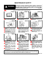
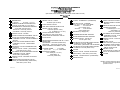
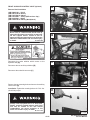
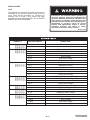
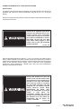
MAINTENANCE SAFETY
WARNING
Instructions are necessary before operating or servicing machine. Read and
understand the Operation & Maintenance Manual, Operator’s Handbook and
signs (decals) on machine. Follow warnings and instructions in the manuals
when making repairs, adjustments or servicing. Check for correct function after
adjustments, repairs or service. Untrained operators and failure to follow
W-2003-0903
instructions can cause injury or death.
Safety Alert Symbol: This symbol with a warning statement, means: “Warning, be alert! Your safety is
involved!” Carefully read the message that follows.
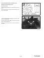
CORRECT
CORRECT
CORRECT
B-10731a
B-12365
B-7469
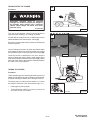
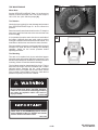
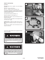
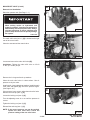
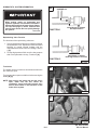
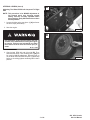
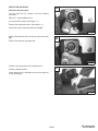
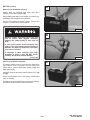
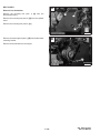
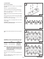
Never service the Bobcat SkidSteer Loader without instructions.
Use the correct procedure to lift or
lower operator cab.
Cleaning and maintenance are
required daily.
WRONG
WRONG
WRONG
B-11799
B-15231
B-15280
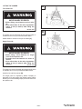
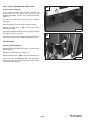
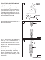
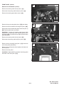
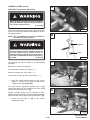
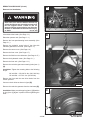
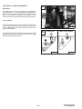
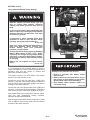
Have good ventilation when
welding or grinding painted
parts.
Wear dust mask when grinding
painted parts. Toxic dust and gas
can be produced.
Avoid exhaust fume leaks which
can kill without warning. Exhaust
system must be tightly sealed.
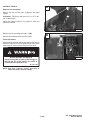
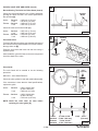
Disconnecting or loosening any
hydraulic tubeline, hose, fitting,
component or a part failure can
cause lift arms to drop. Do not go
under lift arms when raised
unless
supported
by
an
approved lift arm support device.
Replace it if damaged.
Never work on loader with lift
arms up unless lift arms are held
by an approved lift arm support
device. Replace if damaged.
Never modify equipment or add
attachments not approved by
Bobcat Company.
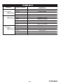
WRONG
WRONG
WRONG
B-6590
B-6580
B-16102
B-6589
B-16102
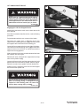
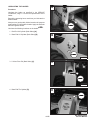
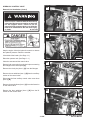
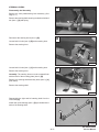
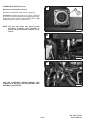
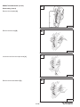
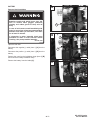
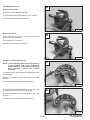
Stop, cool and clean engine of
flammable
materials
before
checking fluids.
Never service or adjust loader
with the engine running unless
instructed to do so in the
manual.
Avoid contact with leaking
hydraulic fluid or diesel fuel
under pressure. It can penetrate
the skin or eyes.
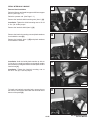
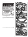
Never fill fuel tank with engine
running, while smoking or when
near open flame.
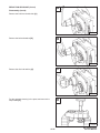
Keep body, jewelry and clothing
away
from
moving
parts,
electrical contact, hot parts and
exhaust.
Wear eye protection to guard
from battery acid, compressed
springs, fluids under pressure
and flying debris when engines
are running or tools are used.
Use eye protection approved for
type of welding.
Keep rear door closed except for
service. Close and latch door
before operating the loader.
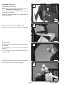
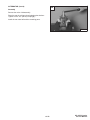
Lead-acid batteries produce
flammable and explosive gases.
Keep arcs, sparks, flames and
lighted tobacco away from
batteries.
Batteries contain acid which
burns eyes or skin on contact.
Wear protective clothing. If acid
contacts body, flush well with
water. For eye contact flush well
and get immediate medical
attention.
Maintenance procedures which are given in the Operation & Maintenance Manual can be performed by the owner/
operator without any specific technical training. Maintenance procedures which are not in the Operation & Maintenance
Manual must be performed ONLY BY QUALIFIED BOBCAT SERVICE PERSONNEL. Always use genuine Bobcat
replacement parts. The Service Safety Training Course is available from your Bobcat dealer.
MSW01-0805
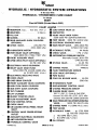
ALPHABETICAL INDEX
GEAR, Camshaft . . . . . . . . . . . . . . . . . . . . . . . . . . . . . . . 7–1
GEAR, Crankshaft . . . . . . . . . . . . . . . . . . . . . . . . . . . . . 7–1
GEAR, Fuel Injection Pump Idler . . . . . . . . . . . . . . . . . 7–1
GEAR AND HUB, Idler . . . . . . . . . . . . . . . . . . . . . . . . . . 7–1
GEARBOX, Fan . . . . . . . . . . . . . . . . . . . . . . . . . . . 1–1, 7–1
GEARCASE, Reduction . . . . . . . . . . . . . . . . . . . . . . . . . 4–1
GEARCASE, Timing . . . . . . . . . . . . . . . . . . . . . . . . . . . . 7–1
GLOW PLUGS . . . . . . . . . . . . . . . . . . . . . . . . . . . . . . . . . 7–1
GRILL, Rear . . . . . . . . . . . . . . . . . . . . . . . . . . . . . . . . . . . 5–1
AIR CLEANER HOUSING . . . . . . . . . . . . . . . . . . . . . . 7–1
ALTERNATOR . . . . . . . . . . . . . . . . . . . . . . . . . . . . . . . . 6–1
AXLE, BEARINGS AND SPROCKET . . . . . . . . . . . . 4–1
BATTERY . . . . . . . . . . . . . . . . . . . . . . . . . . . . . . . . . . . .
BELT, Alternator . . . . . . . . . . . . . . . . . . . . . . . . . . . . . . .
BELT, Drive . . . . . . . . . . . . . . . . . . . . . . . . . . . . . . . . . . .
BOB–TACH . . . . . . . . . . . . . . . . . . . . . . . . . . . . . . . . . .
BOSS UNIT . . . . . . . . . . . . . . . . . . . . . . . . . . . . . . . . . .
BRAKE, Parking . . . . . . . . . . . . . . . . . . . . . . . . . . . . . .
6–1
1–1
3–1
5–1
8–1
4–1
CAMSHAFT . . . . . . . . . . . . . . . . . . . . . . . . . . . . . . . . . .
CHAINS, Drive . . . . . . . . . . . . . . . . . . . . . . . . . . . . . . . .
CHAINCASE FLUID . . . . . . . . . . . . . . . . . . . . . . . . . . .
CODES, Monitor Service . . . . . . . . . . . . . . . . . . . . . . .
CONTROL, Engine Speed . . . . . . . . . . . . . . . . . . . . . .
COVER, Front Chaincase . . . . . . . . . . . . . . . . . . . . . .
COVER, Rear Chaincase . . . . . . . . . . . . . . . . . . . . . . .
COVER, Timing Gearcase . . . . . . . . . . . . . . . . . . . . . .
CRANKSHAFT . . . . . . . . . . . . . . . . . . . . . . . . . . . . . . .
CYLINDER, Hydraulic . . . . . . . . . . . . . . . . . . . . . . . . . .
CYLINDER(S), Lift . . . . . . . . . . . . . . . . . . . . . . . . . . . .
CYLINDER, Tilt . . . . . . . . . . . . . . . . . . . . . . . . . . . . . . .
CYLINDER, Operator Cab Gas . . . . . . . . . . . . . . . . . .
CYLINDER HEAD . . . . . . . . . . . . . . . . . . . . . . . . . . . . .
7–1
4–1
4–1
8–1
7–1
4–1
4–1
7–1
7–1
2–1
2–1
2–1
5–1
7–1
HANDLE, Steering Lever Control (Early Series) . . . . 6–1
HOUSING, Fan Gearbox/Blower . . . . . . . . . . . . . . . . . 7–1
HYDRAULIC/HYDROSTATIC SYSTEM . . . . . . . . . . . 1–1
INFORMATION, Electrical System . . . . . . . . . . . . . . . . 6–1
INFORMATION, Hydraulic System . . . . . . . . . . . . . . . 2–1
INFORMATION, Hydrostatic System . . . . . . . . . . . . . . 3–1
DECIMAL & MILLIMETER EQUIVALENTS . . . . . . . 9–1
DOOR, Rear . . . . . . . . . . . . . . . . . . . . . . . . . . . . . . . . . . 5–1
5–1
1–1
1–1
1–1
6–1
7–1
2–1
1–1
7–1
MOTOR, Hydrostatic . . . . . . . . . . . . . . . . . . . . . . . . . . .
MOUNTS, Engine . . . . . . . . . . . . . . . . . . . . . . . . . . . . . .
MUFFLER, Engine . . . . . . . . . . . . . . . . . . . . . . . . . . . . .
MUFFLER, Spark Arrestor . . . . . . . . . . . . . . . . . . . . . . .
3–1
7–1
7–1
1–1
NOZZLE, Fuel Injector . . . . . . . . . . . . . . . . . . . . . . . . . . 7–1
ENGINE . . . . . . . . . . . . . . . . . . . . . . . . . . . . . . . . . . . . . 7–1
ENGINE COOLING SYSTEM . . . . . . . . . . . . . . . . . . . 1–1
ENGINE LUBRICATION SYSTEM . . . . . . . . . . . . . . . 1–1
FAN, Blower . . . . . . . . . . . . . . . . . . . . . . . . . . . . . . . . . .
FILTER,Hydrostatic Charge Oil . . . . . . . . . . . . . . . . . .
FILTER HOUSING, Hydraulic . . . . . . . . . . . . . . . . . . .
FINAL DRIVE TRANSMISSION (CHAINCASE) . . .
FLYWHEEL . . . . . . . . . . . . . . . . . . . . . . . . . . . . . . . . . .
FUEL SYSTEM . . . . . . . . . . . . . . . . . . . . . . . . . . . . . . .
LIFT ARMS . . . . . . . . . . . . . . . . . . . . . . . . . . . . . . . . . . . .
LIFT ARM SUPPORT DEVICE . . . . . . . . . . . . . . . . . . .
LIFTING AND BLOCKING THE LOADER . . . . . . . . .
LIFTING THE LOADER . . . . . . . . . . . . . . . . . . . . . . . . .
LIGHTS, Front . . . . . . . . . . . . . . . . . . . . . . . . . . . . . . . . .
LINERS, Cylinder . . . . . . . . . . . . . . . . . . . . . . . . . . . . . .
LINKAGE, Pedal Interlock . . . . . . . . . . . . . . . . . . . . . . .
LUBRICATING THE LOADER . . . . . . . . . . . . . . . . . . .
LUBRICATION SYSTEM . . . . . . . . . . . . . . . . . . . . . . . .
OIL COOLER . . . . . . . . . . . . . . . . . . . . . . . . . . . . . . . . . . 3–1
OIL PAN . . . . . . . . . . . . . . . . . . . . . . . . . . . . . . . . . . . . . . 7–1
OPERATOR CAB . . . . . . . . . . . . . . . . . . . . . . . . 1–1 & 5–1
7–1
3–1
2–1
1–1
7–1
1–1
PANEL, BOSS Instrument . . . . . . . . . . . . . . . . . . . . . . .
PANEL, Front . . . . . . . . . . . . . . . . . . . . . . . . . . . . . . . . . .
PANEL, Standard Instrument . . . . . . . . . . . . . . . . . . . .
PEDAL, Parking Brake . . . . . . . . . . . . . . . . . . . . . . . . . .
PEDALS, Control . . . . . . . . . . . . . . . . . . . . . . . . . . . . . . .
PISTONS AND CONNECTING ROD . . . . . . . . . . . . .
PUMP, Hydraulic . . . . . . . . . . . . . . . . . . . . . . . . . . . . . . .
PUMP, Hydrostatic . . . . . . . . . . . . . . . . . . . . . . . . . . . . .
PUMP, Fuel Injection . . . . . . . . . . . . . . . . . . . . . . . . . . . .
PUMP, Oil . . . . . . . . . . . . . . . . . . . . . . . . . . . . . . . . . . . . .
PUMP, Water . . . . . . . . . . . . . . . . . . . . . . . . . . . . . . . . . .
PULLEY, Fixed Tensioner . . . . . . . . . . . . . . . . . . . . . . .
PULLEY, Spring Loaded Tensioner . . . . . . . . . . . . . . .
PULLEY, Fan Drive Tension . . . . . . . . . . . . . . . . . . . . .
BOSS–BOBCAT OPERATION SENSING SYSTEM
Cont’d On Next Page
1
8–1
3–1
6–1
4–1
2–1
7–1
2–1
3–1
7–1
7–1
7–1
3–1
3–1
7–1
ALPHABETICAL INDEX (Cont’d)
RADIATOR . . . . . . . . . . . . . . . . . . . . . . . . . . . . . . . . . . .
RESERVOIR, Hydraulic Fluid . . . . . . . . . . . . . . . . . . .
RELAY SWITCHES . . . . . . . . . . . . . . . . . . . . . . . . . . .
REMOTE START SWITCH . . . . . . . . . . . . . . . . . . . . .
ROCKER ARM AND SHAFT . . . . . . . . . . . . . . . . . . . .
7–1
2–1
6–1
1–1
7–1
SEAL, Axle . . . . . . . . . . . . . . . . . . . . . . . . . . . . . . . . . . .
SEAT BAR RESTRAINT SYSTEM . . . . . . . . . . . . . . .
SENDER AND SENSOR . . . . . . . . . . . . . . . . . . . . . . .
SENSOR, RPM . . . . . . . . . . . . . . . . . . . . . . . . . . . . . . .
SERVICE, Air Cleaner . . . . . . . . . . . . . . . . . . . . . . . . .
SERVICE SCHEDULE . . . . . . . . . . . . . . . . . . . . . . . . .
SHIELD, Drive Belt . . . . . . . . . . . . . . . . . . . . . . . . . . . .
SHIELD, Belt . . . . . . . . . . . . . . . . . . . . . . . . . . . . . . . . .
SPECIFICATIONS, Engine . . . . . . . . . . . . . . . . . . . . .
SPECIFICATIONS, Hyd./Hydr. Fluid . . . . . . . . . . . . .
SPECIFICATIONS, Hydraulic Connection . . . . . . . .
SPECIFICATIONS, Loader . . . . . . . . . . . . . . . . . . . . .
STARTER . . . . . . . . . . . . . . . . . . . . . . . . . . . . . . . . . . . .
STEERING LEVERS . . . . . . . . . . . . . . . . . . . . . . . . . .
4–1
1–1
8–1
8–1
1–1
1–1
3–1
7–1
9–1
9–1
9–1
9–1
6–1
3–1
TANK, Coolant Recovery . . . . . . . . . . . . . . . . . . . . . . . 7–1
TANK, Fuel . . . . . . . . . . . . . . . . . . . . . . . . . . . . . . . . . . . 5–1
TIRE MAINTENANCE . . . . . . . . . . . . . . . . . . . . . . . . . 1–1
THERMOSTAT . . . . . . . . . . . . . . . . . . . . . . . . . . . . . . . 7–1
TROUBLESHOOTING . . . . . . . 2–1, 3–1, 6–1, 7–1, 8–1
TOOL, BOSS Diagnostic . . . . . . . . . . . . . . . . . . . . . . . 8–1
TORQUE, Loader . . . . . . . . . . . . . . . . . . . . . . . . . . . . . 9–1
TORQUE, Specifications For Bolts . . . . . . . . . . . . . . . 9–1
TOWING THE LOADER . . . . . . . . . . . . . . . . . . . . . . . 1–1
TRANSPORTING THE LOADER . . . . . . . . . . . . . . . . 1–1
U.S. TO METRIC CONVERSION . . . . . . . . . . . . . . . . 9–1
VALVE, Bucket Position . . . . . . . . . . . . . . . . . . . . . . . .
VALVE CLEARANCE . . . . . . . . . . . . . . . . . . . . . . . . . .
VALVE, Cold Oil By–Pass . . . . . . . . . . . . . . . . . . . . . .
VALVE, Dual Pressure Main Relief . . . . . . . . . . . . . . .
VALVE, Front Auxiliary Control (Apitech) . . . . . . . . . .
VALVE, Hydraulic Control . . . . . . . . . . . . . . . . . . . . . . .
VALVE, Lock . . . . . . . . . . . . . . . . . . . . . . . . . . . . . . . . . .
VALVE, Main Relief . . . . . . . . . . . . . . . . . . . . . . . . . . . .
VALVE, Select (JEM) . . . . . . . . . . . . . . . . . . . . . . . . . .
VALVES, VALVE SEAT AND GUIDE . . . . . . . . . . . . .
2–1
7–1
3–1
2–1
2–1
2–1
2–1
2–1
2–1
7–1
WATER JACKET TUBE . . . . . . . . . . . . . . . . . . . . . . . . 7–1
2
CONTENTS
FOREWORD . . . . . . . . . . . . . . . . . . . . . . . . . . . . . . . . . . . . . . . . . . . . . . . . . . . . . . ii
SAFETY INSTRUCTIONS . . . . . . . . . . . . . . . . . . . . . . . . . . . . . . . . . . . . . . . . . . . v
SERIAL NUMBER LOCATIONS . . . . . . . . . . . . . . . . . . . . . . . . . . . . . . . . . . . . . vii
DELIVERY REPORT . . . . . . . . . . . . . . . . . . . . . . . . . . . . . . . . . . . . . . . . . . . . . . vii
BOBCAT LOADER IDENTIFICATION . . . . . . . . . . . . . . . . . . . . . . . . . . . . . . . . viii
PREVENTIVE MAINTENANCE . . . . . . . . . . . . . . . . . . . . . . . . . . . . . . . . . . . . 1–1
HYDRAULIC SYSTEM . . . . . . . . . . . . . . . . . . . . . . . . . . . . . . . . . . . . . . . . . . . . 2–1
HYDROSTATIC SYSTEM . . . . . . . . . . . . . . . . . . . . . . . . . . . . . . . . . . . . . . . . . 3–1
DRIVE SYSTEM . . . . . . . . . . . . . . . . . . . . . . . . . . . . . . . . . . . . . . . . . . . . . . . . . 4–1
MAIN FRAME . . . . . . . . . . . . . . . . . . . . . . . . . . . . . . . . . . . . . . . . . . . . . . . . . . . 5–1
ELECTRICAL SYSTEM . . . . . . . . . . . . . . . . . . . . . . . . . . . . . . . . . . . . . . . . . . . 6–1
ENGINE SERVICE . . . . . . . . . . . . . . . . . . . . . . . . . . . . . . . . . . . . . . . . . . . . . . . 7–1
SYSTEM ANALYSIS . . . . . . . . . . . . . . . . . . . . . . . . . . . . . . . . . . . . . . . . . . . . . . 8–1
SPECIFICATIONS . . . . . . . . . . . . . . . . . . . . . . . . . . . . . . . . . . . . . . . . . . . . . . . . 9–1
PREVENTIVE
MAINTENANCE
HYDRAULIC
SYSTEM
HYDROSTATIC
SYSTEM
DRIVE
SYSTEM
Component Repair Manual
A Component Repair Manual is available for this model Bobcat loader.
A component Repair Manual gives complete teardown procedures for service and repair of
all major components such as control valves, hydrostatic pumps and motors, hydraulic
pumps, etc.
MAIN
FRAME
See your Bobcat dealer about availability of this important addition to your service library.
ELECTRICAL
SYSTEM
CALIFORNIA
PROPOSITION 65 WARNING
Diesel engine exhaust and some of its
constituents are known to the State of California
to cause cancer, birth defects and other
reproductive harm.
ENGINE
SERVICE
SYSTEMS
ANALYSIS
SPECIFICATIONS
i
853, 853H Loader
Service Manual
FOREWORD
This manual is for the Bobcat loader mechanic. It provides necessary servicing and adjustment
procedures for the Bobcat loader and its component parts and systems. Refer to the Operation &
Maintenance Manual for operating instructions, starting procedure, daily checks, etc.
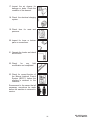
A general inspection of the following items must be made after the loader has had service or repair:
1. Check that the ROPS/FOPS
(Including sidescreens) is in
good condition and is not
modified.
9. Enclosure door latches must
open and close freely.
2. Check that ROPS mounting
hardware is tightened and is
Melroe approved.
10. Bob–Tach
wedges
and
linkages
must
function
correctly and be in good
condition.
3. The seat belt must be correctly
installed, functional and in
good condition.
11. Safety treads must in good
condition.
4. The seat bar and pedal
interlocks must be correctly
adjusted, clean and lubricated.
12. Check for correct function of
indicator lamps (Optional on
some models).
5. Machine signs must be legible
and in the correct location.
13. Check hydraulic fluid level,
engine oil level and fuel supply.
6. Steering levers and foot pedals
must return to neutral.
14. Inspect for fuel, oil or hydraulic
fluid leaks.
7. Check for correct function of
the work lights.
15. Lubricate the loader.
8. The parking brake
function correctly.
16. Check the condition of the
battery and cables.
must
ii
853, 853H Loader
Service Manual
17. Inspect the air cleaner for
damage or leaks. Check the
condition of the element.
18. Check the electrical charging
system.
19. Check tires for wear and
pressure.
20. Inspect for loose or broken
parts or connections.
21. Operate the loader and check
all functions.
22. Check
for
any
field
modification not completed.
23. Check for correct function of
the Bobcat Interlock Control
System (BICS™) before the
machine is returned to the
customer.
Recommend to the owner that all
necessary corrections be made
before the machine is returned to
service.
iii
853, 853H Loader
Service Manual
iv
853, 853H Loader
Service Manual
SAFETY INSTRUCTIONS
Instructions are necessary before operating or servicing machine. Read and understand the Operation &
Maintenance Manual, Handbook and signs (decals) on machine. Follow warnings and instructions in the
manuals when making repairs, adjustments or servicing. Check for correct function after adjustments,
repairs or service. Untrained operators and failure to follow instructions can cause injury or death.
W–2003–0299
The following publications provide information on the safe use and maintenance of the loader and attachments:
• The Delivery Report is used to assure that complete instructions have been given to the new owner and that the machine
is in safe operating condition.
• The Operation & Maintenance Manual delivered with the loader gives operating information as well as routine
maintenance and service procedures. It is a part of the loader and must stay with the machine when it is sold. Replacement
Operation & Maintenance Manuals can be ordered from your Bobcat loader dealer.
• The loader has machine signs (decals) which instruct on the safe operation and care. The signs and their locations are
shown in the Operation & Maintenance Manual. Replacement signs are available from your Bobcat loader dealer.
• The loader has a plastic Operator’s Handbook fastened to the operator cab. Its brief instructions are convenient to the
operator. The Handbook is available from your dealer in an English edition or one of many other languages. See your
Bobcat dealer for more information on translated versions.
• The EMI Safety Manual (available in Spanish) delivered with the loader gives general safety information.
• The Service Manual and Parts Manual are available from your dealer for use by mechanics to do shop–type service and
repair work.
• The Skid–Steer Loader Operator Training Course is available through your local dealer. This course is intended to provide
rules and practices for correct operation of the Bobcat loader. The course is available in English and Spanish version.
• The Service Safety Training Course is available from your Bobcat dealer. This course provides information for safe and
correct service procedures for Bobcat Skid–Steer loaders.
• The Bobcat Skid–Steer Loader Safety Video is available from your Bobcat Dealer.
Warnings on the machine and in the
manuals are for your safety. Failure to
obey warnings can cause injury or
death.
This notice identifies procedures
which must be followed to avoid
damage to the machine.
I–2019–0284
W–2044–1285
Safety Alert Symbol: This symbol with a warning statement, means: “Warning, be alert! Your safety is
involved!” Carefully read the message that follows.
SI05–0299
v
853, 853H Loader
Service Manual
SAFETY INSTRUCTIONS (Cont’d)
• Wear tight fitting clothing. Always wear safety glasses when maintaining or servicing loader. Safety glasses, hearing
protection or loader special applications kit are required for some work. See your dealer for Melroe Safety equipment.
• Know where fire extinguisher and first aid kit are located and how to use them.
• Do not use the Bobcat loader where exhaust, arcs, sparks or hot components can contact flammable material, explosive
dust or gases.
• The engine compartment and engine cooling system must be inspected every day and cleaned if necessary to prevent
fire hazard and overheating.
• Check all electrical wiring and connections for damage. Keep the battery terminals clean and tight. Repair or replace any
damaged part.
• Check fuel and hydraulic tubes, hoses and fittings for damage and leakage. Never use open flame or bare skin to check
for leaks. Tighten or replace any parts that show leakage. Always clean fluid spills. Do not use gasoline or diesel fuel for
cleaning parts. Use commercial nonflammable solvents.
• Follow any environmental safety regulations when disposing of used fluids such as engine oil, grease or anti–freeze.
• Do not use ether or starting fluids on engines which have glow plugs. These starting aids can cause explosion and injure
you or bystanders.
• Always clean the loader and disconnect the battery before doing any welding. Cover rubber hoses, battery and all other
flammable parts. Keep a fire extinguisher near the loader when welding. Have good ventilation when grinding or welding
painted parts. Wear dust mask when grinding painted parts. Toxic dust or gas can be produced.
• Stop the engine and let it cool before adding fuel. No smoking!
• Use the procedure in the Operation & Maintenance or Service Manuals for connecting the battery.
A fire extinguisher is available from your local dealer. The fire extinguisher can be installed in the location shown [A].
A
P–3705
SI06–0398
vi
853, 853H Loader
Service Manual
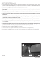
SERIAL NUMBER LOCATIONS
A
Always use the serial number of the loader when
requesting service information or when ordering parts.
Early or later models (identification made by serial
number) may use different parts, or it may be necessary
to use a different procedure in doing a specific service
operation.
LOADER SERIAL NUMBER
The loader serial number plate is located on the inside of
the left upright, above the grill [A].
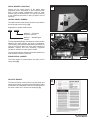
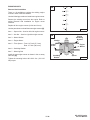
Explanation of loader Serial Number:
XXXX
P–00369
XXXXX
Module 2. – Production
Sequence (Series)
B
Module 1. – Model/Engine
Version
The four digit Model/Engine Combination module number
identifies the model number and engine combination.
This number (in parenthesis beside the model number) is
used in the Service Manual to more easily identify the
standard, optional and field accessory equipment
included or available for each specific model.
The five digit Production Sequence Number identifies the
order which the loader is produced.
ENGINE SERIAL NUMBER
P–00370
The serial number is located above the starter on the
engine block [B].
DELIVERY REPORT
C
The Delivery Report must be filled out by the dealer and
signed by the owner or operator when the Bobcat loader
is delivered. An explanation of the form must be given to
the owner. Make sure it is filled out completely [C].
vii
853, 853H Loader
Service Manual
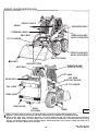
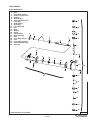
BOBCAT LOADER IDENTIFICATION
FRONT LIGHTS
GRAB HANDLES
OPERATOR SEAT
STEERING LEVER
REAR AUXILIARY
QUICK COUPLERS
SEAT BELT
TILT CYLINDER
FRONT AUXILIARY
QUICK COUPLERS
SAFETY TREAD
BUCKET
BUCKET STEPS
OPERATOR CAB
(ROPS & FOPS)
SEAT BAR
LIFT ARM
LIFT ARM
SUPPORT DEVICE
REAR GRILL
LIFT CYLINDER
TAIL LIGHT
REAR LIGHT
REAR DOOR
REAR
TIE DOWN
TIRES*
B–12555
B–12556
* TIRES – Flotation tires are shown. The Bobcat loader is based–equipped with standard tires.
BUCKET – Several different buckets and other attachments are available for the Bobcat loader.
ROPS, FOPS – Roll Over Protective Structure, per SAE J1040 and ISO 3471 and Falling Object Protective
Structure per SAE J1043 and ISO 3449 Level I. Level ll FOPS is available for protection from heavy falling
objects. The Bobcat loader is base–equipped with a standard operator cab as shown. Extra insulated cab is
available as an option (Reduced noise level).
viii
853, 853H Loader
Service Manual
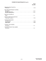
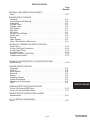
PREVENTIVE MAINTENANCE
Page
Number
PREVENTIVE
MAINTENANCE
AIR CLEANER SERVICE
Replacing Filter Element . . . . . . . . . . . . . . . . . . . . . . . . . . . . . . . . . . . . . . . 1–12
ALTERNATOR BELT
Adjusting The Alternator Belt . . . . . . . . . . . . . . . . . . . . . . . . . . . . . . . . . . . 1–20
ENGINE COOLING SYSTEM
Cleaning The Cooling System . . . . . . . . . . . . . . . . . . . . . . . . . . . . . . . . . . 1–18
Checking The Coolant Level . . . . . . . . . . . . . . . . . . . . . . . . . . . . . . . . . . . . 1–18
Removing Coolant From The Cooling System . . . . . . . . . . . . . . . . . . . . . 1–19
ENGINE LUBRICATION SYSTEM
Checking Engine Oil . . . . . . . . . . . . . . . . . . . . . . . . . . . . . . . . . . . . . . . . . . . 1–16
Replacing Oil And Filter . . . . . . . . . . . . . . . . . . . . . . . . . . . . . . . . . . . . . . . . 1–16
FAN GEARBOX
Checking And Maintaining . . . . . . . . . . . . . . . . . . . . . . . . . . . . . . . . . . . . . . 1–26
FINAL DRIVE TRANSMISSION (CHAINCASE)
Checking And Adding Oil . . . . . . . . . . . . . . . . . . . . . . . . . . . . . . . . . . . . . . . 1–26
FUEL SYSTEM
Filling The Fuel Tank . . . . . . . . . . . . . . . . . . . . . . . . . . . . . . . . . . . . . . . . . .
Fuel Filter . . . . . . . . . . . . . . . . . . . . . . . . . . . . . . . . . . . . . . . . . . . . . . . . . . . .
Fuel Specifications . . . . . . . . . . . . . . . . . . . . . . . . . . . . . . . . . . . . . . . . . . . .
Removing Air From The Fuel System . . . . . . . . . . . . . . . . . . . . . . . . . . . .
1–14
1–14
1–14
1–15
HYDRAULIC/HYDROSTATIC SYSTEM
Checking And Adding Fluid . . . . . . . . . . . . . . . . . . . . . . . . . . . . . . . . . . . . .
Replacing Hydraulic/Hydrostatic Filters . . . . . . . . . . . . . . . . . . . . . . . . . . .
Hydraulic Reservoir Breather Cap . . . . . . . . . . . . . . . . . . . . . . . . . . . . . . .
Replacing Hydraulic Fluid . . . . . . . . . . . . . . . . . . . . . . . . . . . . . . . . . . . . . .
1–21
1–21
1–23
1–22
LIFT ARM SUPPORT DEVICE
Engaging The Lift Arm Support Device . . . . . . . . . . . . . . . . . . . . . . . . . . . 1–7
Disengaging The Lift Arm Support Device . . . . . . . . . . . . . . . . . . . . . . . . 1–8
LIFTING AND BLOCKING THE LOADER
Procedure . . . . . . . . . . . . . . . . . . . . . . . . . . . . . . . . . . . . . . . . . . . . . . . . . . . . 1–4
LIFTING THE LOADER
Four Point Lift . . . . . . . . . . . . . . . . . . . . . . . . . . . . . . . . . . . . . . . . . . . . . . . . 1–6
Single Point Lift . . . . . . . . . . . . . . . . . . . . . . . . . . . . . . . . . . . . . . . . . . . . . . . 1–6
LUBRICATING THE LOADER
Procedure . . . . . . . . . . . . . . . . . . . . . . . . . . . . . . . . . . . . . . . . . . . . . . . . . . . . 1–27
OPERATOR CAB
Description . . . . . . . . . . . . . . . . . . . . . . . . . . . . . . . . . . . . . . . . . . . . . . . . . . .
Lowering The Operator Cab . . . . . . . . . . . . . . . . . . . . . . . . . . . . . . . . . . . .
Raising The Operator Cab . . . . . . . . . . . . . . . . . . . . . . . . . . . . . . . . . . . . . .
Emergency Exit . . . . . . . . . . . . . . . . . . . . . . . . . . . . . . . . . . . . . . . . . . . . . . .
–1–1–
1–9
1–10
1–9
1–10
853, 853H Loader
Service Manual
PREVENTIVE MAINTENANCE (Cont’d)
Page
Number
REMOTE START SWITCH
Procedure . . . . . . . . . . . . . . . . . . . . . . . . . . . . . . . . . . . . . . . . . . . . . . . . . . . . 1–29
SEAT BAR RESTRAINT SYSTEM
Description . . . . . . . . . . . . . . . . . . . . . . . . . . . . . . . . . . . . . . . . . . . . . . . . . . . 1–11
Seat Bar Inspection . . . . . . . . . . . . . . . . . . . . . . . . . . . . . . . . . . . . . . . . . . . 1–11
Seat Bar Maintenance . . . . . . . . . . . . . . . . . . . . . . . . . . . . . . . . . . . . . . . . . 1–11
SERVICE SCHEDULE
Chart . . . . . . . . . . . . . . . . . . . . . . . . . . . . . . . . . . . . . . . . . . . . . . . . . . . . . . . . 1–3
SPARK ARRESTOR MUFFLER
Cleaning Procedure . . . . . . . . . . . . . . . . . . . . . . . . . . . . . . . . . . . . . . . . . . . 1–24
TIRE MAINTENANCE
Tire Mounting . . . . . . . . . . . . . . . . . . . . . . . . . . . . . . . . . . . . . . . . . . . . . . . . . 1–25
Tire Rotation . . . . . . . . . . . . . . . . . . . . . . . . . . . . . . . . . . . . . . . . . . . . . . . . . . 1–25
Wheel Nuts . . . . . . . . . . . . . . . . . . . . . . . . . . . . . . . . . . . . . . . . . . . . . . . . . . . 1–25
TOWING THE LOADER
Procedure . . . . . . . . . . . . . . . . . . . . . . . . . . . . . . . . . . . . . . . . . . . . . . . . . . . . 1–5
TRANSPORTING THE LOADER
Procedure . . . . . . . . . . . . . . . . . . . . . . . . . . . . . . . . . . . . . . . . . . . . . . . . . . . . 1–5
–1–2–
853, 853H Loader
Service Manual
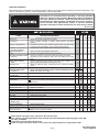
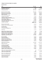
SERVICE SCHEDULE
Maintenance work must be done at regular intervals. Failure to do so will result in excessive wear and early failures. The
service schedule is a guide for correct maintenance of the Bobcat loader.
Instructions are necessary before operating or servicing machine.
Read and understand the Operation Maintenance Manual, Handbook
and signs (decals) on machine. Follow warnings and instructions in
the manual when making repairs, adjustments or servicing. Check for
correct function after adjustments, repairs or service. Untrained
operators and failure to follow instructions can cause injury or death.
W–2003–0199
ITEM
Engine Oil
Air Cleaner
Engine Cooling System
Lift Arms, Cyl., Bob–Tach
Pivot Pins & Wedges
Engine Air System
Tires
Seat Belt, Seat Bar & Pedal
Interlocks
Safety Signs & Safety
Tread
Operator Cab
Fuel Filter
Hydraulic Fluid, Hoses
& Tubelines
Final Drive Transmission
(Chaincase)
Battery
Control Pedals & Steering
Wheel Nuts
Parking Brake
Alternator Belt
Engine Oil & Filter
Spark Arrestor Muffler
Engine/Hydro. Drive Belt
Fuel Filter
Seat Bar
Steering Shaft
Hyd./Hydro. Filter
Hydraulic Reservoir
Breather Cap
Fan Drive Gearbox
Final Drive Transmission
Hydraulic Reservoir
Hydraulic Motors
SERVICE REQUIRED
8–10
50
100
250 1000
Check the oil level and add oil as needed.
Check condition indicator or display panel. Service only when
required.
Clean debris from oil cooler, radiator and grill. Check coolant level cold
in recovery tank. See Page 1–18 for correct coolant mixture.
Lubricate with multi–purpose lithium based grease (12 places).
Check for leaks and damaged components.
Check for damaged tires and correct air pressure.
Check the condition of seat belt. Check the seat bar and pedal
interlocks for correct operation. Clean dirt and debris from moving
parts.
Check for damaged signs (decals) and safety tread. Replace any
signs or safety treads that are damaged or worn.
Check the fastening bolts, washers and nuts. Check the condition
of cab.
Remove the trapped water.
Check fluid level and add as needed. Check for damage and leaks.
Repair and replace as needed.
Check oil level.
Check cables and electrolyte level.
Check for correct operation. Repair or adjust as needed.
Check for loose wheel nuts and tighten to 105–115 ft.–lbs. (142–156
Nm) torque.
Check operation.
Check tension and adjust as needed.
Replace oil and filter.
Clean the spark chamber.
* Check for wear or damage. Adjust as needed.
Replace filter element.
Grease pivots as needed.
Grease three fittings.
Replace the filter element.
Replace the reservoir breather cap.
Check gear lube level.
Replace the oil in the chaincase.
Replace the fluid.
Replace the two case drain filters.
Check wheel nut torque every 8 hours for the first 24 hours.
Also replace hydraulic/hydrostatic filter element when the transmission warning light comes ON.
Or every 12 months.
* Inspect the new belt after first 50 hours.
Clean or replace case drain filters in the event of any major hydraulic or hydrostatic repair.
–1–3–
853, 853H Loader
Service Manual
A
Instructions are necessary before operating or
servicing machine. Read and understand the
Operation & Maintenance Manuals, Handbook
and signs (decals) on machine. Follow
warnings and instructions in the manuals when
making repairs, adjustments or servicing.
Check for correct function after adjustments,
repairs or service. Untrained operators and
failure to follow instructions can cause injury
or death.
W–2003–0199
Read the Removal & Installation, Disassembly &
Assembly, etc. completely to become familiar with the
procedure before beginning [A].
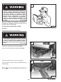
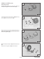
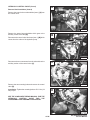
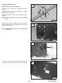
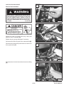
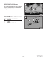
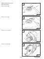
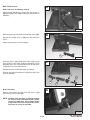
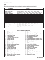
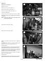
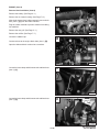
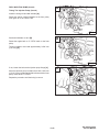
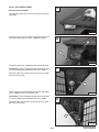
LIFTING AND BLOCKING THE LOADER
B–07023
Procedure
Always park the loader on a level surface.
Put jackstands under the front axles and rear
corners of the frame before running the engine
for service. Failure to use jackstands can allow
the machine to fall or move and cause injury or
death.
B
W–2017–0286
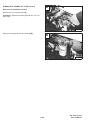
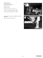
Put floor jack under the rear of the loader [B].
Lift the rear of the loader and install jackstands [B].
CD–11160
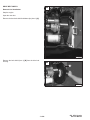
Put the floor jack under the front the loader [C].
C
Lift the front of the loader and put jackstands under the
axle tubes [C].
NOTE: Make sure the jackstands do not touch the
tires.
CD–11159
–1–4–
853, 853H Loader
Service Manual
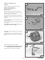
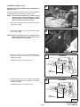
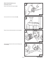
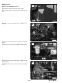
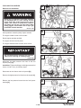
TRANSPORTING THE LOADER
A
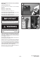
Procedure
Adequately designed ramps of sufficient
strength are needed to support the weight of
the machine when loading onto a transport
vehicle. Wood ramps can break and cause
personal injury.
W–2058–0494
MC–01241
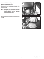
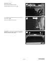
The rear of the transport vehicle must be blocked or
supported when loading or un–loading the loader.
B
A loader with an empty bucket or no attachment must be
loaded backward onto the transport vehicle [A].
Be sure the transport and towing vehicles are of adequate
size and capacity.
Use the following procedure to fasten the Bobcat loader
to the transport vehicle to prevent the loader from moving
during sudden stops or when going up or down slopes [B].
P–05090
Lower the bucket or attachment to the floor. Stop the
engine. Engage the parking brake. Install chains at the
front and rear loader tie down positions (Inset) [B]. Fasten
each end of the chain to the transport vehicle and tighten
the chain with a chain tightener.
P–05077
TOWING THE LOADER
Procedure
To prevent damage to the loaders hydrostatic system, the
loader must be towed only a short distance at slow speed.
(Example: Moving the loader onto a transport vehicle.)
The towing chain (or cable) must be rated at 1–1/2 times
the weight of the loader. (See Specification Page 9–1.)
•
Disengage the parking brake.
•
Tow the Bobcat at 2 MPH (3,2 km/hr.) or less for not
more than 25 feet (7,6 meters).
6707867
–1–5–
MC–01242
853, 853H Loader
Service Manual
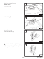
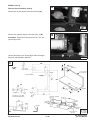
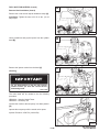
LIFTING THE LOADER
A
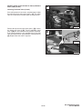
Four Point Lift
AVOID INJURY OR DEATH
• Before lifting, check fasteners on four point
lift.
• Never allow riders in the cab or bystanders
within 15 feet (5 meters) while lifting the
machine.
MC–01434
W–2046–1290
B
The loader can be lifted with the four point lift which is
available as a kit from your Bobcat loader dealer.
Attach cables or chains to lift eyes as shown [A].
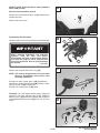
Single Point Lift
MC–01664
AVOID INJURY OR DEATH
• Before lifting, check fasteners on single
point lift and operator cab.
• Assemble front cab fasteners as shown in
manual.
• Never allow riders in the cab or bystanders
within 15 feet (5 meters) while lifting the
machine.
W–2007–1285
The loader can also be lifted with the single point lift which
is available as a kit from your Bobcat loader dealer.
Install the kit and lift as shown [B].
The single point lift, supplied by Melroe Company is
designed to lift and support the Bobcat loader without
affecting roll over and falling object protection features of
the operator cab.
–1–6–
853, 853H Loader
Service Manual
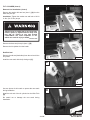
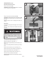
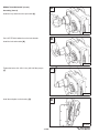
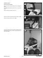
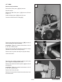
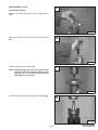
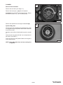
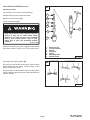
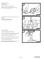
LIFT ARM SUPPORT DEVICE
A
1
Never work on a machine with the lift arms up
unless the lift arms are secured by a lift arm
support device. Failure to use an approved lift
arm support device can allow the lift arms or
attachment to fall and cause injury or death.
2
W–2059–0991
P–02133
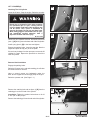
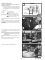
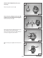
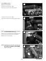
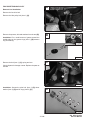
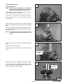
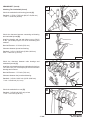
Engaging the Lift Arm Support Device
Maintenance and service work can be done with the lift
arms lowered.
B
If the lift arms must be raised for service, use the following
procedure:
Put jackstands under the rear corners of the loader.
1
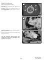
Disconnect the spring (Item 1) [A] from the lift arm
support device retaining pin (Item 2) [A]. Hold onto the lift
arm support device and remove the retaining pin.
Lower the lift arm support device on top of the lift cylinder.
Hook the free end of the spring (Item 1) [B] to the lift arm
support device so there will be no interference with the
support device engagement.
P–02118
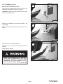
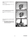
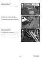
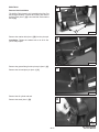
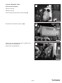
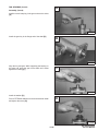
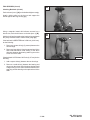
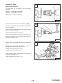
With the operator in the seat, seat belt fastened and seat
bar lowered, start the engine.
C
Raise the lift arms, until the lift arm support device drops
onto the lift cylinder rod [C].
Lower the lift arms slowly until the support device is held
between the lift arm and the lift cylinder. Stop the engine.
Raise the seat and move pedals until both pedals lock.
Install pin (Item 1) [C] into the rear of the lift arm support
device below the cylinder rod.
1
P–00095
Service lift arm support device if damaged or if
parts are missing. Using a damaged lift arm
support or with missing parts can cause lift
arms to drop causing injury or death.
W–2271–1197
–1–7–
853, 853H Loader
Service Manual
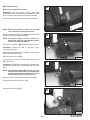
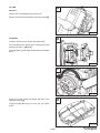
LIFT ARM SUPPORT DEVICE (Cont’d)
A
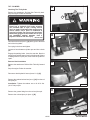
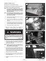
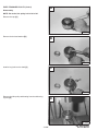
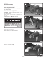
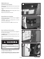
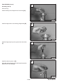
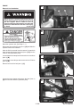
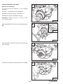
Disengaging The Lift Arm Support Device
Remove the pin from the lift arm support device.
1
Connect the spring (Item 1) [A] from the lift arm support
device to the bracket below the lift arms.
With the operator in the seat, seat belt fastened and seat
bar lowered, start the engine.
Raise the lift arms a small amount and the spring will lift
the support device off the lift cylinder rod.
P–01542
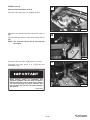
Lower the lift arms. Stop the engine.
Raise the seat bar and move pedals until both pedals
lock.
B
Disconnect the spring from the bracket.
Raise the support device into storage position and insert
pin through lift arm support device and bracket [B].
Connect spring to pin.
P–02133
–1–8–
853, 853H Loader
Service Manual
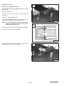
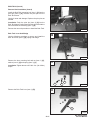
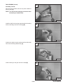
OPERATOR CAB
A
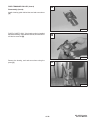
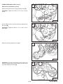
Description
The Bobcat loader has an operator cab (ROPS and
FOPS) as standard equipment to protect the operator
from rollover and falling objects. Check with your dealer
if the operator cab has been damaged. The seat belt must
be worn for roll over protection.
ROPS/FOPS Roll Over Protective Structure per SAE
J104 and ISO 3471, and Falling Object Protective
Structure per SAE J1043 and ISO 3449, Level l. Level ll
is available.
1
Level l – Protection from falling bricks, small concrete
blocks and hand tools encountered in operations such as
highway maintenance, landscaping, and other
construction site services.
CD–15126
B
Level ll – Protection from falling trees, rocks; for machines
involved in site clearing, overhead demolition or forestry.
Never modify operator cab by welding,
grinding, drilling holes or adding attachments
unless instructed to do so by Melroe Company.
Changes to the cab can cause loss of operator
protection from rollover and falling objects,
and result in injury or death.
CD–15125
W–2069–1285
C
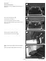
Raising The Operator Cab
Stop the loader on a level surface. Lower the lift arms. If
the lift arms must be up while raising the operator cab,
install the lift arm support device. (See Page 1–7.)
Loosen the nut (Item 1) [A] (both sides) at the front corner
of the operator cab.
Remove the nut and plate (both sides) [B].
Lift on the grab handle and bottom of the operator cab
slowly until the cab latching mechanism engages and the
cab is all the way up [C].
P–00380
Before the cab or the lift arms are raised for
service, jackstands must be put under the rear
corners of the frame. Failure to use jackstands
may allow the machine to tip backward causing
injury or death.
W–2014–1285
–1–9–
853, 853H Loader
Service Manual
OPERATOR CAB (Cont’d)
A
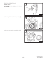
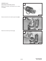
Lowering The Operator Cab
NOTE: Make sure the seat bar is fully raised or
lowered when lowering the cab.
Pull down on the bottom of the operator cab until it stops
at the latching mechanism.
Release the latching mechanism (Item 1) [A] and pull the
cab all the way down.
1
CD–15124
B
Install the plate and nut (Item 1) [B] (both sides).
Tighten the nuts to 40–50 ft.–lbs. (54–68 Nm) torque [B].
1
CD–15126
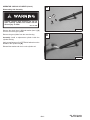
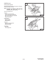
Emergency Exit
C
The front opening on the operator cab and rear window
provide exits.
To exit through the rear window, use the following
procedure:
Pull on the tag on the top of the rear window to remove the
rubber cord [C].
P–00660
Push the rear window out of the rear of the operator cab.
Exit through the rear of the operator cab [D].
D
P–00383
–1–10–
853, 853H Loader
Service Manual
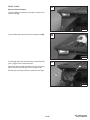
SEAT BAR RESTRAINT SYSTEM
A
Description
The seat bar restraint system has a pivoting seat bar with
arm rests and has spring loaded interlocks for the lift and
tilt control pedals.
The operator controls the use of the seat bar. The seat bar
in the down position helps to keep the operator in the seat.
The interlocks require the operator to lower the seat bar
in order to operate the foot pedal.
Clean &
Lubricate
When the seat bar is up, the lift and tilt pedals are locked
when returned to the NEUTRAL POSITION.
P–00384
B
AVOID INJURY OR DEATH
The seat bar system must lock the lift and tilt
control pedals in neutral when the seat bar is
up. Service the system if pedals do not lock
correctly.
W–2105–1285
Clean
Pedal Lock
Shield
Inspecting The Seat Bar
Sit in the seat and fasten the seat belt. Engage the
parking brake. Pull the seat bar all the way down. Start the
engine. Operate each foot pedal to check both the lift and
tilt functions. Raise the lift arms until the bucket is about
2 feet (600 mm) off the ground.
P–01223
Raise the seat bar. Try to move each foot pedal. Pedals
must be firmly locked in neutral position. There must be
no motion of the lift arms or tilt (bucket) when the pedals
are pushed.
Pull the seat bar down, lower the lift arms. Operate the lift
pedals. While the lift arms are going up, raise the seat bar
and the lift arms should stop.
Lower the seat bar, lower the lift arms and place the
bucket flat on the ground. Stop the engine. Raise the seat
bar and operate the foot pedals to be sure that the pedals
are firmly locked in the neutral position. Unbuckle the seat
belt.
Maintaining The Seat Bar
See the SERVICE SCHEDULE, Page 1–3 for correct
service interval.
Clean any debris or dirt from the moving parts [A] & [B].
Inspect the linkage bolts and nuts for tightness. The
correct torque is 25–28 ft.–lbs. (34–38 Nm).
Use a general purpose grease to lubricate the seat bar
pivot points at each side of the cab [A].
If the seat bar system does not function correctly, check
for free movement of each linkage part. Check for
excessive wear. Adjust pedal control linkage.
Replace parts that are worn or damaged. Use only
genuine Melroe replacement parts.
–1–11–
853, 853H Loader
Service Manual
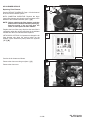
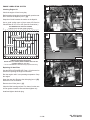
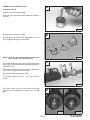
AIR CLEANER SERVICE
A
Replacing Filter Element
1
2
See the SERVICE SCHEDULE, Page 1–3 for the interval
to service the air cleaner system.
WITH CONDITION INDICATOR: Replace the large
(outer) filter element only when the red ring shows in the
window of the condition indicator (Item 1) [A].
NOTE: Before replacing the filter element, push the
button on the condition indicator (Item 2) [A].
Start the engine. If the red ring does not
show, do not replace the filter element.
Replace the inner filter every third time the outer filter is
replaced or when the red ring still shows in the indicator
window after the outer filter has been replaced.
CD–15118
B
WITH BOSS® OPTION: It is important to change the air
filter element only when the service codes (on the
BOSS® option instrument panel) shows the symbols
[AF.2] [B].
MC–02042
Service the air cleaner as follows:
Remove the dust cover wing nut (Item 1) [C].
C
Remove the dust cover.
1
CD–15117
–1–12–
853, 853H Loader
Service Manual
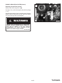
AIR CLEANER SERVICE (Cont’d)
A
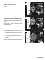
Replacing Filter Element (Cont’d)
Remove the wing nut (Item 1) [A] at the large air filter
element.
1
CD–15119
B
Remove the large filter element [B].
NOTE: Make sure all sealing surfaces are free of dirt
and debris.
Install the new filter element and washer and tighten the
wing nut.
Check the air intake hose for damage. Check the air
cleaner housing for damage. Check to make sure all
connections are tight.
CD–15120
Inner Filter Element:
Only replace the inner filter element under the following
conditions:
C
1. Replace the inner filter element every third time the
outer filter is replaced.
2. If the service codes show symbols, Page 8–1,
during full engine speed, replace the inner filter
element only after the outer filter element has been
changed.
1
Remove the inner filter wing nut (Item 1) [C] to remove the
filter element.
CD–15121
–1–13–
853, 853H Loader
Service Manual
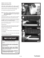
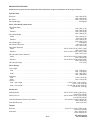
FUEL SYSTEM
A
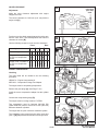
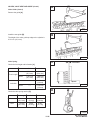
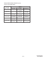
Fuel Specifications
Use only clean, high quality diesel fuel, Grade No. 1 or
Grade No. 2 .
The following is one suggested blending guideline which
should prevent fuel gelling problems:
Temp. F° (C°)
No. 2
No.1
+15°(9°)
Down to –20° (–29°)
Below –20° (29°)
100%
50%
0%
0%
50%
100%
1
We recommend an operator contact their fuel supplier for
local recommendations.
P–02124
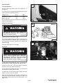
Filling The Fuel Tank
B
WRONG
Stop and cool the engine before adding fuel.
NO SMOKING! Failure to obey warnings can
cause an explosion or fire.
W–2063–0887
Remove the fuel fill cap (Item 1) [A].
Use a clean, approved safety container to add fuel of the
correct specifications. Add fuel only in an area that has
free movement of air and no open flames or sparks. NO
SMOKING! [B].
B–13456
C
Install and tighten the fuel fill cap [A].
Fuel Filter
2
Always clean up spilled fuel or oil. Keep heat,
flames, sparks or lighted tobacco away from
fuel and oil. Failure to use care around
combustibles can cause explosion or fire
which can result in injury or death.
1
CD–15123
W–2103–1285
See the SERVICE SCHEDULE, Page 1–3 for the service
interval when to remove the water from the fuel filter.
Loosen the drain (Item 1) [C] at the bottom of the filter
element to drain any water from the filter.
See the SERVICE SCHEDULE, Page 1–3 for the service
interval when to replace the fuel filter.
To replace the fuel filter element (Item 2) [C], use a filter
wrench to remove the filter element.
Clean the area around the filter housing. Put oil on the
seal of the new filter element. Install the fuel filter, and
hand tighten. Remove the air from the fuel system. ( See
Page 1–15.)
–1–14–
853, 853H Loader
Service Manual
FUEL SYSTEM (Cont’d)
A
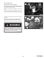
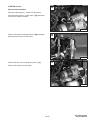
Removing Air From The Fuel System
After replacing the fuel filter element or when the fuel tank
has run out of fuel, the air must be removed from the fuel
system prior to starting the engine.
1
Loosen the air vent plug (Item 1) [A] at the top of the fuel
filter.
2
Operate the priming bulb (Item 2) [A] until fuel flows from
the filter vent. Tighten the fuel filter vent plug (Item 1) [A].
CD–15123
B
Loosen the air vent plug at the top of the fuel injection
pump [B].
Again operate the priming bulb (Item 2) [A] until fuel flows
from the air vent plug with no air bubbles showing.
Tighten the air vent plug at the fuel injection pump [B].
Always clean up spilled fuel or oil. Keep heat,
flames, sparks or lighted tobacco away from
fuel and oil. Failure to use care around
combustibles can cause explosion or fire
which can result in injury or death.
CD–10847
W–2103–1285
–1–15–
853, 853H Loader
Service Manual
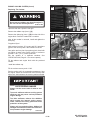
ENGINE LUBRICATION SYSTEM
A
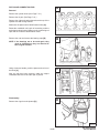
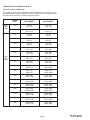
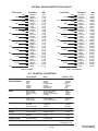
Checking Engine Oil
Check the engine oil level every day.
Before starting the engine for the work shift, open the rear
door. Remove the dipstick (Item 1) [A].
1
Keep the oil level between the marks on the dipstick.
Use a good quality motor oil that meets API Service
Classification of CC, CD or CE. (See Oil Chart below.)
RECOMMENDED SAE VISCOSITY NUMBER
(LUBRICATION OILS FOR DIESEL ENGINE CRANKCASE)
C°
–40
–34
–29
–23
–18
–13
–7
–1
+4
+10
+15
+21
+27
+32
+38
+43 +49
CD–15112
SAE 40W or 20W–50
B
SAE 10W–30
SAE 15W–40
SAE 30W
* SAE 5W–30
SAE 20W–20
1
SAE 10W
SYNTHETIC OIL Use recommendation from Synthetic Oil Mfgr.
–40 –30
–20
–10
0
+10
+20
+30
+40
+50
+60
+70
+80
CD–15113
+90 +100 +110 +120
F°
TEMPERATURE RANGE ANTICIPATED
BEFORE NEXT OIL CHANGE (DIESEL ENGINES MUST USE API
CLASSIFICATION CD, CF4, CG4 )
C
* Can be used ONLY when available with appropriate diesel rating.
Replacing Oil And Filter
See the SERVICE SCHEDULE, Page 1–3 for the service
interval for replacing the engine oil and filter.
Run the engine until it is at operating temperature. Stop
the engine.
1
Open the rear door. Remove the drain plug (Item 1) [B].
Drain the oil into a container.
Remove the oil filter (Item 1) [C].
CD–15122
Clean the filter housing surface. Put clean oil on the new
oil filter gasket. Install the filter and hand tighten only.
Install and tighten the drain plug.
–1–16–
853, 853H Loader
Service Manual
ENGINE LUBRICATION SYSTEM (Cont’d)
A
Replacing Oil And Filter (Cont’d)
Remove the oil filler cap (Item 1) [A].
Put 8 qts. (7,6 L) of oil in the engine. (See Oil Chart, Page
1–16.)
Start the engine and let it run for several minutes. Stop the
engine. Check for leaks at the oil filter. Add oil as needed
if it is not at the top mark on the dipstick.
1
CD–15114
Always clean up spilled fuel or oil. Keep heat,
flames, sparks or lighted tobacco away from
fuel and oil. Failure to use care around
combustibles can cause explosion or fire
which can result in injury or death.
W–2103–1285
–1–17–
853, 853H Loader
Service Manual
ENGINE COOLING SYSTEM
A
Checking The Coolant Level
Check the cooling system every day to prevent
over–heating, loss of performance or engine damage.
Open the rear door. Check the coolant level in the coolant
recovery tank on the right side of the engine [A].
The coolant recovery tank must be 1/3 full.
NOTE: The loader is factory filled with propylene
glycol coolant. DO NOT mix propylene glycol
with ethylene glycol.
CD–10853
Propylene Glycol
B
Add premixed coolant, 47% water and 53% propylene
glycol to the recovery tank if the coolant level is low.
One gallon and one pint of propylene glycol mixed with
one gallon of water is the correct mixture of coolant to
provide a –34°F (–37°C) freeze protection.
Use a refractometer to check the condition of propylene
glycol in your cooling system.
Ethylene Glycol
Add premixed coolant, 50% water and 50% ethylene
glycol to the recovery tank if the coolant level is low.
Cleaning The Cooling System
P–00378
Raise the rear grill.
C
Use air pressure or water pressure to clean the top of the
oil cooler [B].
Raise the oil cooler and clean the top of the radiator [C].
Check cooling system for leaks.
AVOID ENGINE DAMAGE
P–00381
Always use the correct ratio of water to antifreeze.
Too much antifreeze reduces cooling system
efficiency and may cause serious premature
engine damage.
Too little antifreeze reduces the additives
which protect the internal engine components; reduces the boiling point and freeze
protection of the system.
Always add a premixed solution. Adding full
strength concentrated coolant can cause serious premature engine damage.
I–2124–0497
–1–18–
853, 853H Loader
Service Manual
ENGINE COOLING SYSTEM (Cont’d)
A
Replacing The Coolant
1
Do not remove radiator cap when the engine is
hot. You can be seriously burned.
W–2070–1285
Open the rear door. Open the rear grill.
P–00379
Remove the radiator cap (Item 1) [A].
B
Remove the drain plug (Item 1) [B] from the side of the
engine block. Drain the coolant into a container.
After all the coolant is removed, install and tighten the
drain plug.
Propylene Glycol
Add premixed coolant; 47% water and 53% propylene
glycol to the recovery tank if the coolant level is low.
One gallon and one pint of propylene glycol mixed with
one gallon of water is the correct mixture of coolant to
provide a –34°F (–37°C) freeze protection.
1
Mix the coolant in a separate container See
SPECIFICATIONS, Page 9–1 for correct capacity.
CD–10854
Fill the radiator and engine block with the premixed
coolant.
Install the radiator cap.
Fill the coolant recovery tank 1/3 full.
Run the engine until it is at operating temperature. Stop
the engine. Check the coolant level in the recovery tank
when cool. Add coolant to the recovery tank as needed.
AVOID ENGINE DAMAGE
Always use the correct ratio of water to antifreeze.
Too much antifreeze reduces cooling system
efficiency and may cause serious premature
engine damage.
Too little antifreeze reduces the additives
which protect the internal engine components; reduces the boiling point and freeze
protection of the system.
Always add a premixed solution. Adding full
strength concentrated coolant can cause serious premature engine damage.
I–2124–0497
–1–19–
853, 853H Loader
Service Manual
ALTERNATOR BELT
A
Adjusting The Alternator Belt
2
Stop the engine.
1
Raise the operator cab. (See Page 1–8.)
Loosen the alternator mounting bolt (Item 1) [A].
Loosen the adjustment bolt (Item 2) [A].
Move the alternator until the belt has 5/16 inch (8,0 mm)
movement at the middle of the belt span with 15 lbs. (66
N) of force.
CD–09339
–1–20–
853, 853H Loader
Service Manual
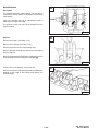
HYDRAULIC/HYDROSTATIC SYSTEM
A
Checking And Adding Fluid
Use only recommended fluid in the hydraulic system See
SPECIFICATIONS, Page 9–1 for the correct fluid.
To check the reservoir, use the following procedure:
Put the Bobcat loader on a level surface. Lower the lift
arms and tilt the Bob–Tach fully back.
Stop the engine.
Remove the dipstick [A].
CD–15162
The fluid level must be between the marks on the dipstick.
B
If fluid is needed, remove the fill cap (Item 1) [B].
NOTE: Before installing the fill cap, make sure the
rubber gasket is installed on the fill cap (Inset
[B].
CD–15135
1
CD–15161
Add the fluid as needed to bring the level to the top mark
on the dipstick [A].
C
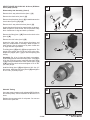
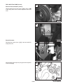
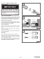
1
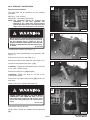
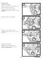
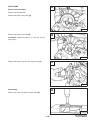
Replacing Hydraulic/Hydrostatic Filters
See the SERVICE SCHEDULE, Page 1–3 for the correct
service interval.
Raise the operator cab. (See Page 1–8.)
Use a filter wrench and remove the filter elements (Item
1 & 2) [C].
1
Clean the surface of the filter housing where the element
seal contacts the housing. Put clean oil on the rubber seal
of the filter element.
CD–10855
Install and hand tighten the filter elements.
–1–21–
853, 853H Loader
Service Manual
HYDRAULIC/HYDROSTATIC SYSTEM (Cont’d)
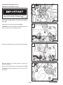
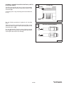
A
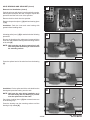
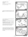
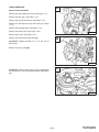
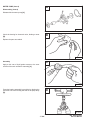
Replacing The Hydraulic Fluid
See the SERVICE SCHEDULE, Page 1–3 for the service
interval.
The fluid must also be replaced if it becomes
contaminated or after major repairs.
CD–15135
1
Remove the reservoir fill cap (Item 1) [A].
NOTE: Before installing the fill cap, make sure the
rubber gasket is installed on the fill cap
(Inset) [A].
Remove the screen (Item 1) [B] and thoroughly clean with
clean solvent.
CD–15161
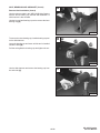
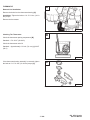
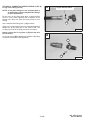
Raise the operator cab. (See Page 1–8.)
B
NOTE: Case drain filters are added to later model
loaders listed below:
1
S/N 510125001 & Above
S/N 510250001 & Above
S/N 510374001 & Above
Remove the two case drain filters (Item 1) [C] &[D] (one
for each hydrostatic motor) and clean thoroughly or
replace filters.
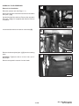
When all the fluid is removed from the reservoir, connect
and tighten the filters and case drain hoses.
Add the correct fluid to the reservoir until the fluid level is
between the marks on the dipstick. DO NOT fill above the
top mark on the dipstick.
CD–15163
C
Lower the operator cab. Start the engine and operate the
loader hydraulic controls.
1
Lower the lift arms. Stop the engine. Check for leaks.
Check the fluid level in the reservoir and add as needed.
P–00971
Always clean up spilled fuel or oil. Keep heat,
flames, sparks or lighted tobacco away from
fuel and oil. Failure to use care around
combustibles can cause explosion or fire
which can result in injury or death.
D
W–2103–1285
1
P–00969
–1–22–
853, 853H Loader
Service Manual
HYDRAULIC/HYDROSTATIC SYSTEM (Cont’d)
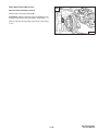
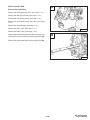
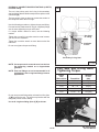
A
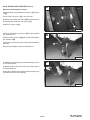
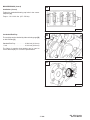
Hydraulic Reservoir Breather Cap
See SERVICE SCHEDULE, Page 1–3 for the correct
service interval.
Remove the breather cap [A].
NOTE: Make sure the rubber gasket is installed on
the breather cap (Inset) [A].
CD–15134
Make sure the baffle washer is installed in the hydraulic
reservoir [B].
CD–15132
B
CD–15133
–1–23–
853, 853H Loader
Service Manual
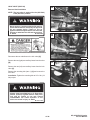
SPARK ARRESTOR MUFFLER
A
Cleaning Procedure
See the SERVICE SCHEDULE, Page 1–3 for service
interval for cleaning the spark arrestor muffler.
Do not operate the loader with a defective exhaust
system.
1
CD–15172
This loader is factory equipped with a U.S.D.A.
Forestry Service approved spark arrestor
muffler. It is necessary to do maintenance on
this spark arrestor muffler to keep it in working
condition. The spark arrestor muffler must be
serviced by dumping the spark chamber every
100 hours of operation.
If this machine is operated on flammable forest,
brush or grass covered land, it must be
equipped with a spark arrestor attached to the
exhaust system and maintained in working
order. Failure to do so will be in violation of
California State Law, Section 4442 PRC.
When an engine is running in an enclosed area,
fresh air must be added to avoid concentration
of exhaust fumes. If the engine is stationary,
vent the exhaust outside. Exhaust fumes
contain odorless, invisible gases which can kill
without warning.
W–2050–1285
Make reference to local laws and regulations for
spark arrestor requirements.
Stop engine and allow the muffler to cool before
cleaning the spark chamber. Wear safety
glasses or goggles. Failure to obey can cause
serious injury.
I–2022–0595
Stop the engine. Open the rear door and rear grill.
W–2011–1285
Never use machine in atmosphere with
explosive dust or gases or where exhaust can
contact flammable material. Failure to obey
warnings can cause injury or death.
Remove the plug (Item 1) [A] from the bottom of the
muffler.
W–2068–1285
When the engine is running during service, the
steering levers must be in neutral and the
parking brake engaged. Failure to do so can
cause injury or death.
W–2006–0284
Start the engine and run for about 10 seconds while a
second person, wearing safety glasses, holds a piece of
wood over the outlet of the muffler.
Stop the engine. Put anti–seize coating on plug. Install
and tighten the plug. Lower the rear grill and close the rear
door.
–1–24–
853, 853H Loader
Service Manual
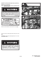
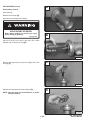
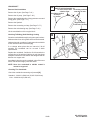
TIRE MAINTENANCE
A
Wheel Nuts
See the SERVICE SCHEDULE, Page 1–3 for the service
interval to check the wheel nuts. The correct torque is
105–115 ft.–lbs. (142–156 Nm) torque [A].
Tire Rotation
Check the tires regularly for wear, damage and pressure
See SPECIFICATIONS Page 9–1 for the correct tire
pressure.
Rear tires usually wear faster than front tires. To keep tire
wear even, move the front tires to the rear and rear tires
to the front [B].
CD–15165
B
It is important to keep the same size tires on each side of
the loader. If different sizes are used, each tire will be
turning at a different rate and cause excessive wear. The
tread bars of all the tires must face the same direction.
Recommended tire pressure must be maintained to avoid
excessive tire wear and loss of stability and handling
capability. Check for the correct pressure before
operating the loader.
Tire Mounting
Tires are to be repaired only by an authorized person
using the proper procedures and safety equipment. Tires
and rims must always be checked for correct size before
mounting. Check rim and tire bead for damage.
B–09976
The rim flange must be cleaned and free of rust. The tire
bead and rim flange must be lubricated with a rubber
lubricant before mounting the tire, avoid excessive
pressure which can rupture the tire and cause serious
injury or death. During inflation of the tire, check the tire
pressure frequently to avoid over inflation.
Do not inflate tires above specified pressure.
Failure to use correct tire mounting procedure
can cause an explosion which can result in
injury or death.
W–2078–1285
Inflate tires to the MAXIMUM pressure shown
on the sidewall of the tire. DO NOT mix brands
of tires used on the same loader.
I–2057–0794
–1–25–
853, 853H Loader
Service Manual
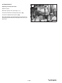
FINAL DRIVE TRANSMISSION (CHAINCASE)
A
853,853HServiceManual#6720755–PreventiveMaintenanceSectionPart1of2
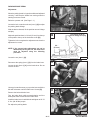
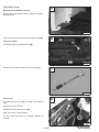
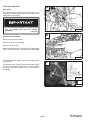
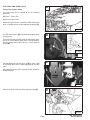
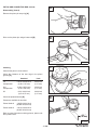
Checking And Adding Oil
1
The chaincase contains the final drive sprockets and
chains and uses the same type of oil as the
hydraulic/hydrostatic system See SPECIFICATIONS,
Page 9–1.
To check the chaincase oil level, use the following
procedure:
Drive the loader on a level surface. Stop the engine.
Remove the plug (Item 1) [A] from the front of the
chaincase housing.
P–01551
If oil can be reached with the tip of the your finger through
the hole the oil level is correct.
B
If the level is low, add oil through the check plug hole until
the oil flows from the hole. Install and tighten the plug.
FAN GEARBOX
Checking And Maintaining
1
See the SERVICE SCHEDULE, Page 1–3 for the correct
service interval.
Raise the operator cab. (See Page 1–8.)
Remove the plug (Item 1) [B] to check the lubricant level.
CD–15164
If the level is low, add SAE 90W gear lube through the
check plug hole until the lubricant flows from the hole.
Install and tighten the plug.
–1–26–
853, 853H Loader
Service Manual
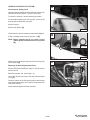
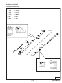
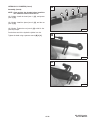
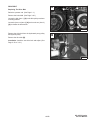
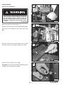
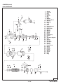
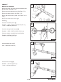
LUBRICATING THE LOADER
A
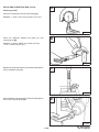
Procedure
Lubricate the loader as specified in the SERVICE
SCHEDULE, Page 1–3 for the best performance of the
loader.
Record the operating hours each time you lubricate the
Bobcat loader.
1
Always use a good quality lithium based multi–purpose
grease when you lubricate the loader. Apply the lubricant
until extra grease shows.
Lubricate the following locations on the loader:
CD–15169
1. Rod End Lift Cylinder (Both Sides) [A].
2. Base End Lift Cylinder (Both Sides) [B].
B
2
CD–15171
3. Lift Arm Pivot Pin (Both Sides) [C].
C
3
CD–15170
D
4. Base End Tilt Cylinder [D].
4
CD–15168
–1–27–
853, 853H Loader
Service Manual
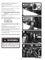
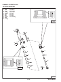
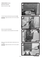
LUBRICATING THE LOADER (Cont’d)
A
Procedure (Cont’d)
5. Rod End Tilt Cylinder [A].
5
CD–15167
6. Bob–Tach Pivot Pin (Both Sides) [B].
B
7. Bob–Tach Wedge (Both Sides) [B].
6
7
CD–15166
8. 250 Hours: Steering Lever Shaft and Centering
Mechanism [C].
C
8
P–07609
–1–28–
853, 853H Loader
Service Manual
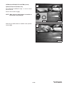
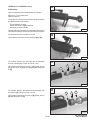
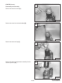
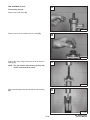
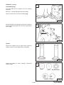
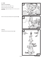
REMOTE START SWITCH
A
853,853HServiceManual#6720755–PreventiveMaintenanceSectionPart2of2
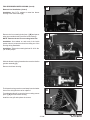
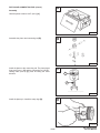
Procedure
1
The tool listed will be needed to do the following
procedure:
MEL1398 – Remote Start Switch
MEL1416 – Adapter Harness (853 Base Only)
The remote start switch is required when the service
technician is adjusting the steering linkage, checking the
hydraulic/hydrostatic system.
Lift and block the loader. (See Page 1–4.)
CD–11144
Raise the operator cab. (See Page 1–8.)
Disconnect the operator cab wire harness from the
engine wire harness.
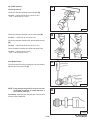
B
Connect the remote start switch to the engine harness
connectors (Item 1) [A].
853 Base Only: Use MEL1416 adapter harness (Item 1)
[B]. Connect the adapter harness to the remote start
switch.
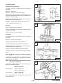
Disconnect the operator cab wire harness from the
engine wire harness.
1
P–01190
C
Connect the adapter harness (Item 1) [C] to the engine
harness connectors.
1
Put jackstands under the front axles and rear
corners of the frame before running the engine
for service. Failure to use jackstands can allow
the machine to fall or move and cause injury or
death.
W–2017–0286
P–01191
Never work on a machine with the lift arms up
unless the lift arms are secured by an approved
lift arm support device. Failure to use an
approved lift arm support device can allow the
lift arms or attachment to fall and cause injury
or death.
W–2059–0598
–1–29–
853, 853H Loader
Service Manual
–1–30–
853, 853H Loader
Service Manual
HYDRAULIC SYSTEM
Page
Number
BUCKET POSITION VALVE (S/N 5102) & (S/N 5103)
Removal And Installation . . . . . . . . . . . . . . . . . . . . . . . . . . . . . . . . . . . . . . . 2–40
CONTROL PEDALS
Pedal Adjustment . . . . . . . . . . . . . . . . . . . . . . . . . . . . . . . . . . . . . . . . . . . . . 2–42
Removal And Installation . . . . . . . . . . . . . . . . . . . . . . . . . . . . . . . . . . . . . . . 2–42
DUAL PRESSURE MAIN RELIEF VALVE (S/N 512811001 & Above)
W/Select Valve(JEM)
Adjusting The Low Setting . . . . . . . . . . . . . . . . . . . . . . . . . . . . . . . . . . . . . .
Adjusting The High Setting . . . . . . . . . . . . . . . . . . . . . . . . . . . . . . . . . . . . .
Checking The Low Setting . . . . . . . . . . . . . . . . . . . . . . . . . . . . . . . . . . . . . .
Checking The High Setting . . . . . . . . . . . . . . . . . . . . . . . . . . . . . . . . . . . . .
HYDRAULIC
SYSTEM
2–26
2–27
2–23
2–24
FRONT AUXILIARY CONTROL VALVE (Apitech)
Removal And Installation . . . . . . . . . . . . . . . . . . . . . . . . . . . . . . . . . . . . . . . 2–41
HYDRAULIC CONTROL VALVE
Removal And Installation . . . . . . . . . . . . . . . . . . . . . . . . . . . . . . . . . . . . . . . 2–28
HYDRAULIC CYLINDER
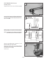
Assembly . . . . . . . . . . . . . . . . . . . . . . . . . . . . . . . . . . . . . . . . . . . . . . . . . . . .
Disassembly . . . . . . . . . . . . . . . . . . . . . . . . . . . . . . . . . . . . . . . . . . . . . . . . . .
Lift Cylinder Identification . . . . . . . . . . . . . . . . . . . . . . . . . . . . . . . . . . . . . . .
Tilt Cylinder Identification . . . . . . . . . . . . . . . . . . . . . . . . . . . . . . . . . . . . . . .
2–17
2–15
2–13
2–14
HYDRAULIC FLUID RESERVOIR
Removal And Installation . . . . . . . . . . . . . . . . . . . . . . . . . . . . . . . . . . . . . . . 2–38
HYDRAULIC PUMP
Checking The Output Of The Pump . . . . . . . . . . . . . . . . . . . . . . . . . . . . . 2–36
Removal And Installation . . . . . . . . . . . . . . . . . . . . . . . . . . . . . . . . . . . . . . . 2–37
HYDRAULIC SYSTEM INFORMATION
Tighten Procedure . . . . . . . . . . . . . . . . . . . . . . . . . . . . . . . . . . . . . . . . . . . . . 2–7
HYDRAULIC FILTER HOUSING
Removal And Installation . . . . . . . . . . . . . . . . . . . . . . . . . . . . . . . . . . . . . . . 2–35
LIFT CYLINDER(S)
Checking The Lift Cylinder . . . . . . . . . . . . . . . . . . . . . . . . . . . . . . . . . . . . . 2–9
Removal And Installation . . . . . . . . . . . . . . . . . . . . . . . . . . . . . . . . . . . . . . . 2–9
LOCK VALVE (S/N 5103)
Removal And Installation . . . . . . . . . . . . . . . . . . . . . . . . . . . . . . . . . . . . . . . 2–39
MAIN RELIEF VALVE
Checking The Main Relief Valve . . . . . . . . . . . . . . . . . . . . . . . . . . . . . . . . . 2–20
Checking The Main Relief Valve Without Auxiliaries . . . . . . . . . . . . . . . . 2–21
Removal And Installation . . . . . . . . . . . . . . . . . . . . . . . . . . . . . . . . . . . . . . . 2–22
PEDAL INTERLOCK LINKAGE
Pedal Interlock Linkage Adjustment . . . . . . . . . . . . . . . . . . . . . . . . . . . . . . 2–44
Removal And Installation . . . . . . . . . . . . . . . . . . . . . . . . . . . . . . . . . . . . . . . 2–43
–2–1–
853, 853H Loader
Service Manual
HYDRAULIC SYSTEM (Cont’d)
Page
Number
SELECT VALVE (JEM) (S/N 512811001 & Above)
Checking The Relief Valve . . . . . . . . . . . . . . . . . . . . . . . . . . . . . . . . . . . . . .
Disassembly And Assembly . . . . . . . . . . . . . . . . . . . . . . . . . . . . . . . . . . . .
Removal And Installation . . . . . . . . . . . . . . . . . . . . . . . . . . . . . . . . . . . . . . .
Solenoid Testing . . . . . . . . . . . . . . . . . . . . . . . . . . . . . . . . . . . . . . . . . . . . . .
2–30
2–33
2–32
2–34
TILT CYLINDER
Checking The Tilt Cylinder . . . . . . . . . . . . . . . . . . . . . . . . . . . . . . . . . . . . . . 2–11
Removal And Installation . . . . . . . . . . . . . . . . . . . . . . . . . . . . . . . . . . . . . . . 2–11
Rod End Seal . . . . . . . . . . . . . . . . . . . . . . . . . . . . . . . . . . . . . . . . . . . . . . . . . 2–12
TROUBLESHOOTING
Chart . . . . . . . . . . . . . . . . . . . . . . . . . . . . . . . . . . . . . . . . . . . . . . . . . . . . . . . . 2–7
–2–2–
853, 853H Loader
Service Manual
HYDRAULIC SYSTEM INFORMATION
–2–3–
853, 853H Loader
Service Manual
HYDRAULIC SYSTEM INFORMATION (Cont’d)
–2–4–
853, 853H Loader
Service Manual
HYDRAULIC SYSTEM INFORMATION (Cont’d)
–2–5–
853, 853H Loader
Service Manual
–2–6–
853, 853H Loader
Service Manual
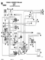
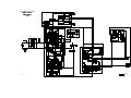
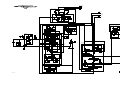
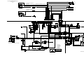
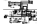
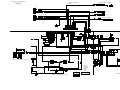
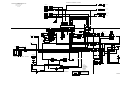
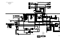
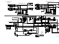
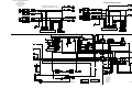
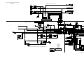
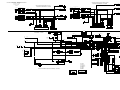
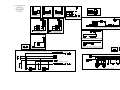
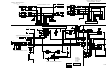
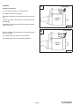
HYDRAULIC/HYDROSTATIC SCHEMATIC
853 (S/N 508411001-15215)
(S/N 510125001-26791)
(S/N 510250001-50691)
(Printed June 1999)
MC2396LU
LEGEND
1 RESERVOIR:
C apacity . . . 15.5 Qts (14,7 L)
2 SPRING LOADED FILTER BYPASS
VALVE: 45-55 PSI (311-379 kPa)
3 DIFFERENTIAL PRESSURE SWITCH:
36-44 PSI (248-303 kPa)
853 PLUS - Normally Closed
853 BASE - Normally Closed
4 CHECK VALVE - FILTER
5 FLOW DIVIDER ADJUSTMENT VALVE
6 PILOT ACTIVATED DIRECTIONAL
CONTROL VALVE - FLOW CONTROL
SPOOL
7 PILOT ACTIVATED DIRECTIONAL
CONTROL VALVE - UNLOADING
SPOOL
8 CONTROL VALVE POWER-BEYOND
OUTLET
9 RELIEF VALVE - PORT: (OPTIONAL)
3100 PSI (21371 kPa)
10 SOLENOID ACTIVATED DIRECTIONAL
CONTROL VALVE - AUXILIARY
(OPTIONAL)
11 CHECK VALVE - BUCKET POSITION
VALVE
12 RELIEF/ANTICAVITATION VALVE PORT (TILT BASE END) (OPTIONAL):
2500 PSI (17238 kPa)
13 RELIEF VALVE - PORT:
3500 PSI (24132 kPa)
14 LOAD CHECK VALVE
15 ONE WAY RESTRICTOR VALVE
16 RELIEF VALVE - MAIN:
2550-2600 PSI (17582-17927 kPa)
at Front Quick Couplers
17 SHUTTLE RELIEF VALVE:
225-290 PSI (1551-2000 kPa )
18 DRIVE MOTOR SHUTTLE VALVE
19 TOW VALVE
20 RELIEF/REPLENISHING VALVE - HIGH
PRESSURE:
STANDARD . 4350 PSI (29990 kPa)
OPTIONAL . 5000 PSI (34475 kPa )
21 DISPLACEMENT CONTROL VALVE
22 CHARGE PUMP . . . . 11.0 GPM
(41,6 L./M
in.) at 2850 RPM
23 HYDRAULIC PUMP
18.0 GPM (68,1 L/min.)
at 2750 RPM
24 FILTER
25 RELIEF VALVE - CHARGE:
140°F. (60°C.) Fluid at Full RPM
Neutral . . . . 310-330 PSI
(2137-2275 kPa)
Stroked . . . . 3O0-320 PSI
(2069-2206 kPa)
26 MUFFLER (If Equipped )
37 FIXED CAPACITY DISPLACEMENT
BIDIRECTIONAL HYDROSTATIC
MOTOR
38 ANTICAVITATION VALVE
39 PILOT TO OPEN CHECK VALVE
40 FILTER
27 CHARGE PRESSURE SENSOR
28 FLUID TEMPERATURE SENSOR
29 BYPASS VALVE - COLD OIL
85 PSI (596 kPa)
30 SOLENOID ACTIVATED DIRECTIONAL
CONTROL VALVE - FRONT
AUXILIARY (OPTIONAL ON 853 BASE)
31 SOLENOID ACTIVATED DIRECTIONAL
CONTROL VALVE (TWO COIL)
32 FILTER
33 RELIEF VALVE - FRONT AUXILIARY
2400-2600 PSI (16548-17927 kPa)
34 FILTER - HYDROSTATIC (CANISTER)
35 RESTRICTION
36 FILTER - HYDRAULIC (CANISTER)
NOTE: Unless otherwise specified
springs have NO significant
pressure value.
Printed in U.S.A.
MC2396LU (5-19-99)
MALE
FEMALE
FRONT AUXILIARY VALVE (OPTIONAL)
(APITECH)
FRONT AUXILIARY (OPTIONAL)
MALE
30
30
32
FEMALE
SECONDARY FRONT AUXILIARY (OPTIONAL)
33
31
LOCK VALVE (OPTIONAL)
FEMALE
39
35
35
MALE
REAR AUXILIARY (OPTIONAL)
RIGHT DRIVE MOTOR
HYDRAULIC
FILTER
17
18
BUCKET POSITION VALVE (OPTIONAL)
D
36
5
11
2
3
4
37
HYDROSTATIC
FILTER
A
11
HYDROSTATIC PUMPS
28
34
27
24
7
19
2
PORT
BLOCK
OIL
COOLER
C
6
B
20
21
29
1
3
23
OUTLET
22
OUTLET
8
HYDRAULIC
CONTROL VALVE
INLET
INLET
9
26
10
40
25
10
AUXILIARY
SPOOL
T1LT CYLINDER
12
21
TILT CYLINDER
SPOOL
20
13
14
15
LIFT CYLINDER
19
LEFT DRIVE MOTOR
37
38
LIFT CYLINDER SPOOL
14
16
17
Printed in U.S.A.
18
WORKING CIRCUITS
PILOT PRESSURE
DRAIN CIRCUITS
COMPONENTS
MC2396U (5-19-99)
HYDRAULIC/HYDROSTATIC SCHEMATIC
853 (S/N 508415216-17999)
(S/N 510126792 AND ABOVE)
(S/N 510250692 AND ABOVE)
(S/N 512811001-15999)
(Printed June 1999)
MC2397LU
LEGEND
1 RESERVOIR:
C apacity
. . . 15.5 Qts (14,7 L)
2 SPRING LOADED FILTER BYPASS
VALVE: 45-55 PSI (311-379 kPa)
3 DIFFERENTIAL PRESSURE SWITCH:
36-44 PSI (248-303 kPa)
853 PLUS - Normally Closed
853 BASE - N ormally Closed
4 CHECK VALVE - FILTER
5 FLOW DIVIDER ADJUSTMENT VALVE
6 PILOT ACTIVATED DIRECTIONAL
CONTROL VALVE - FLOW CONTROL
SPOOL
7 PILOT ACTIVATED DIRECTIONAL
CONTROL VALVE - UNLOADING
SPOOL
8 PILOT ACTIVATED DIRECTIONAL
CONTROL VALVE - FOR REAR
AUXILIARY - NORMALLY OPEN
("D2")
9 RELIEF VALVE - PORT: (OPTIONAL)
3100 PSI (21371 kPa)
10 SOLENOID ACTIVATED DIRECTIONAL
CONTROL VALVE - AUXILIARY
(OPTIONAL)
11 CHECK VALVE - BUCKET POSITION
VALVE
12 RELIEF/ANTICAVITATION VALVE PORT (TILT BASE END):
2500 PSI (17238 kPa)
13 RELIEF VALVE - PORT:
3500 PSI (24132 kPa)
14 LOAD CHECK VALVE
15 ONE WAY RESTRICTOR VALVE
16 RELIEF VALVE - MAIN:
2550-2600 PSI (17582-17927 kPa)
at Front Quick Couplers
17 SHUTTLE RELIEF VALVE:
225-290 PSI (1551-2000 kPa )
18 DRIVE MOTOR SHUTTLE VALVE
19 TOW VALVE
20 RELIEF/REPLENISHING VALVE - HIGH
PRESSURE:
STANDARD . 4350 PSI (29990 kPa)
OPTIONAL . 5000 PSI (34475 kPa)
21 DISPLACEMENT CONTROL VALVE
22 CHARGE PUMP . . . . 11.0 GPM
(41,6 L./M in .) at 2850 RPM
23 HYDRAULIC PUMP
18.0 GPM (68,1 L/min.)
at 2750 RPM
24 FILTER
25 RELIEF VALVE - CHARGE:
140°F. (60°C.) F luid at Full
RPM
Neutral . . . . 310-330 PSI
(2137-2275 kPa )
Stroked . . . . 3O0-320 PSI
(2069-2206 kPa)
26 MUFFLER (If Equipped)
39
ANTICAVITATION VALVE
27 CHARGE PRESSURE SENSOR
28 FLUID TEMPERATURE SENSOR
29 PILOT ACTIVATED DIRECTIONAL
CONTROL VALVE - FOR REAR
AUXILIARY - NORMALLY OPEN
("D1")
30 SOLENOID ACTIVATED DIRECTIONAL
CONTROL VALVE - FRONT
AUXILIARY (OPTIONAL ON 853 BASE)
31 PILOT ACTIVATED DIRECTIONAL
CONTROL VALVE - FOR REAR
AUXILIARY - NORMALLY CLOSED
("P1" and "F1")
32 FILTER
33 SOLENOID ACTIVATED DIRECTIONAL
CONTROL VALVE
34 FILTER - HYDROSTATIC (CANISTER)
35 PILOT ACTIVATED DIRECTIONAL
CONTROL VALVE - FOR REAR
AUXILIARY - NORMALLY CLOSED
("P2" and "F2")
36 FILTER - HYDRAULIC (CANISTER)
37 FILTER
Printed in U.S.A.
38 FIXED CAPACITY DISPLACEMENT
BIDIRECTIONAL HYDROSTATIC
MOTOR
NOTE: Unless otherwise specified,
springs have NO significant
pressure value.
DIVERTER VALVE (OPTIONAL)
FRONT AUXILIARY
D2
(S/N 510126792 AND ABOVE)
(S/N 510250692 AND ABOVE)
MALE
D1
FEMALE
29
8
P1
30
P2
31
33
REAR AUXILIARY
FEMALE
F1
35
MALE
F2
32
RIGHT DRIVE MOTOR
HYDRAULIC
FILTER
17
18
BUCKET POSITION VALVE (OPTIONAL)
D
36
5
11
2
3
4
38
HYDROSTATIC
FILTER
A
11
HYDROSTATIC PUMPS
34
27
24
28
7
19
2
C
6
B
20
21
OIL
COOLER
1
3
23
OUTLET
22
OUTLET
HYDRAULIC
CONTROL VALVE
INLET
INLET
9
26
10
37
25
10
AUXILIARY
SPOOL
T1LT CYLINDER
12
21
TILT CYLINDER
SPOOL
20
13
14
15
LIFT CYLINDER
19
LEFT DRIVE MOTOR
38
39
LIFT CYLINDER SPOOL
14
16
17
Printed in U.S.A.
18
WORKING CIRCUITS
PILOT PRESSURE
DRAIN CIRCUITS
COMPONENTS
MC2397U (5-19-99)
(S/N 512811001-15999 WITH APITECH AUXILIARY VALVE)
LEGEND
1 RESERVOIR:
C apacity . . . 15.5 Q ts (14,7 L)
2 SPRING LOADED FILTER BYPASS
VALVE: 45-55 PSI (311-379 kPa )
3 DIFFERENTIAL PRESSURE SWITCH:
36-44 PSI (248-303 kPa)
853 PLUS - N ormally Closed
853 BASE - N ormally Closed
4 CHECK VALVE - FILTER
5 FLOW DIVIDER ADJUSTMENT VALVE
6 PILOT ACTIVATED DIRECTIONAL
CONTROL VALVE - FLOW CONTROL
SPOOL
7 PILOT ACTIVATED DIRECTIONAL
CONTROL VALVE - UNLOADING
SPOOL
8 CONTROL VALVE POWER-BEYOND
OUTLET
9 RELIEF VALVE - PORT: (OPTIONAL)
3100 PSI (21371 kPa)
10 SOLENOID ACTIVATED DIRECTIONAL
CONTROL VALVE - REAR
AUXILIARY (OPTIONAL)
11 CHECK VALVE - BUCKET POSITION
VALVE
12 RELIEF/ANTICAVITATION VALVE PORT (TILT BASE END) (OPTIONAL)
2500 PSI (17238 kPa)
Printed in U.S.A.
13 RELIEF VALVE - PORT:
3500 PSI (24132 kPa)
14 LOAD CHECK VALVE
15 ONE WAY RESTRICTOR VALVE
16 RELIEF VALVE - MAIN:
3300 PSI (22750 kPa )
at 18 GPM (68,1 L/ min.)
17 SHUTTLE RELIEF VALVE:
225-290 PSI (1551-2000 kPa)
18 DRIVE MOTOR SHUTTLE VALVE
19 TOW VALVE
20 RELIEF/REPLENISHING VALVE - HIGH
PRESSURE:
STANDARD . 4350 PSI (29990 kPa)
OPTIONAL . 5000 PSI (34475 kPa)
21 DISPLACEMENT CONTROL VALVE
22 CHARGE PUMP . . . . 11.0 GPM
(41,6 L./M
in.) at 2850 RPM
23 HYDRAULIC PUMP
18.0 GPM (68,1 L/ min.)
2750 RPM at
1150 PSI (7929 kPa)
24 FILTER - HYDRAULIC (CANISTER)
25 RELIEF VALVE - CHARGE:
140°F. (60°C.) F luid at Full RPM
N eutral . . . . 310-330 PSI
(2137-2275 kPa)
Stroked . . . . 3O0-320 PSI
(2069-2206 kPa)
26 MUFFLER (I f Equipped)
36 FIXED CAPACITY DISPLACEMENT
BIDIRECTIONAL HYDROSTATIC
MOTOR
37 ANTICAVITATION VALVE
38 HYDRAULIC PUMP
6.0 GPM (22,7 L/ min.)
2750 RPM at
1150 PSI (7929 kPa)
39 SOLENOID ACTIVATED DIRECTIONAL
CONTROL VALVE - FLOW
FLUID TEMPERATURE SENSOR
SELECTIVE VALVE
40 CHECK VALVE - FLOW SELECTIVE
BYPASS VALVE - COLD OIL
VALVE
85 PSI (596 kPa)
41 RELIEF VALVE
SOLENOID ACTIVATED DIRECTIONAL
3200-3400 PSI (22061-23439 kPa)
CONTROL VALVE - FRONT
AUXILIARY (OPTIONAL ON 853 BASE) 42 SOLENOID ACTIVATED DIRECTIONAL
CONTROL VALVE - RELIEF
SOLENOID ACTIVATED DIRECTIONAL
SELECTIVE VALVE
CONTROL VALVE (TWO COIL)
43 RELIEF VALVE
FILTER
2750-2850 PSI (18958-19648 kPa)
kPa)
44 PILOT TO OPEN CHECK VALVE
RELIEF VALVE - FRONT AUXILIARY
(OPTIONAL) . 2500 PSI (17235 kPa)
45 FILTER
FILTER - HYDROSTATIC (CANISTER)
27 CHARGE PRESSURE SENSOR
28
29
30
31
32
33
34
35 RESTRICTION
NOTE: Unless otherwise specified
springs have NO significant
pressure value.
MC2398LU (5-19-99)
30
30
32
33
31
35
17
35
44
18
24
5
11
2
3
36
28
34
4
11
27
2
8
32
19
7
20
9
21
29
6
38
3
1
10
10
22
23
26
12
45
25
14
13
15
21
37
20
14
19
16
36
40
39
42
43
17
Printed in U.S.A.
18
41
WORKING CIRCUITS
PILOT PRESSURE
DRAIN CIRCUITS
COMPONENTS
MC2398U (5-19-99)
HYDRAULIC/HYDROSTATIC SCHEMATIC
HI-FLOW MACHINE
853 (S/N 512811001-15999 WITH JEM AUXILIARY VALVE)
(Printed June 1999)
MC2399LU
LEGEND
1 RESERVOIR:
C apacity . . . 16.0 Q ts (15,1 L)
2 SPRING LOADED FILTER BYPASS
VALVE: 45-55 PSI (311-379 kPa)
3 DIFFERENTIAL PRESSURE SWITCH:
36-44 PSI (248-303 kPa)
Standard Loader - Normally Open
B.O.S.S. L oader - Normally Closed
4 CHECK VALVE - FILTER
5 FLOW DIVIDER ADJUSTMENT VALVE
6 PILOT ACTIVATED DIRECTIONAL
CONTROL VALVE - FLOW CONTROL
SPOOL
7 PILOT ACTIVATED DIRECTIONAL
CONTROL VALVE - UNLOADING
SPOOL
8 RELIEF VALVE - PORT: (OPTIONAL)
2500 PSI (17238 kPa)
9 SOLENOID ACTIVATED DIRECTIONAL
CONTROL VALVE - AUXILIARY
10 CHECK VALVE - BUCKET POSITION
VALVE
11 RELIEF/ANTICAVITATION VALVE PORT (TILT BASE END) (OPTIONAL)
2500 PSI (17238 kPa)
12 RELIEF VALVE - PORT:
3500 PSI (24132 kPa)
13 LOAD CHECK VALVE
23 CHARGE PUMP . 14.0-15.0 GPM
(52,9-56,7 L/ min.) at 2700 RPM
24 FILTER
14 ONE WAY RESTRICTOR VALVE
25 RELIEF VALVE - CHARGE:
140°F. (60°C.) Fluid at Full RPM
N eutral . . . . 310-330 PSI
(2137-2275 kPa)
Stroked . . . . 3O0-320 PSI
(2069-2206 kPa)
26 MUFFLER (If Equipped)
15 RELIEF VALVE - MAIN:
at Front Quick Couplers
SYSTEM MAIN RELIEF:
2800 PSI (19306 kPa)
HI FLOW MAIN RELIEF:
3300 PSI (22754 kPa)
16 SHUTTLE RELIEF VALVE:
290 PSI (2000 kPa)
17 DRIVE MOTOR SHUTTLE VALVE
18 TOW VALVE
19 RELIEF/REPLENISHING VALVE - HIGH
PRESSURE:
STANDARD . 4350 PSI (29990 kPa)
OPTIONAL . 5000 PSI (34475 kPa)
20 DISPLACEMENT CONTROL VALVE
21 AUXILIARY HYDRAULIC PUMP:
6.0 GPM (22,7 L/ min.)
at 2750 RPM
at 1150 PSI (7929 kPa)
22 HYDRAULIC PUMP . . . .Gear Type
PUMP CAPACITY:
18.0 GPM (68,1 L/min.)
HI FLOW CAPACITY: (Includes 23 )
24.0 GPM (90,8 L/ min.)
at 2750 RPM
at 1150 PSI (7929 kPa)
Printed in U.S.A.
38 FIXED CAPACITY DISPLACEMENT
BIDIRECTIONAL HYDROSTATIC
MOTOR
39 ANTICAVITATION VALVE
40 FILTER
27 CHARGE PRESSURE SENSOR
28 FLUID TEMPERATURE SENSOR
29 PILOT TO OPEN CHECK VALVE
30 SOLENOID ACTIVATED DIRECTIONAL
CONTROL VALVE - FRONT
AUXILIARY
31 RELIEF VALVE - MAIN HIGH FLOW
3000 PSI (20685 kPa)
32 RESTRICTION
33 SOLENOID ACTIVATED DIRECTIONAL
CONTROL VALVE
34 SOLENOID ACTIVATED DIRECTIONAL
CONTROL VALVE (TWO COIL)
35 FILTER - HYDROSTATIC (CANISTER)
36 FILTER - HYDRAULIC (CANISTER)
37 COLD OIL BYPASS VALVE
NOTE: Unless otherwise specified
springs have NO significant
pressure value.
MC2399LU (5-19-99)
FRONT AUXILIARY
FEMALE
AUXILIARY VALVE (JEM)
MALE
F2
F1
29
29
32
32
CASE DRAIN
FRONT AUXILIARY
D1
34
33
31
RIGHT DRIVE MOTOR
FEMALE
D2
MALE
30
HYDRAULIC
FILTER
16
17
BUCKET POSITION VALVE (OPTIONAL)
D
36
5
10
2
3
4
38
HYDROSTATIC
FILTER
A
HYDROSTATIC PUMPS
35
28
10
27
24
7
18
2
C
6
19
B
20
PORT
BLOCK
OIL
COOLER
37
1
23
3
22
OUTLET
21
OUTLET
HYDRAULIC
CONTROL
VALVE
INLET
INLET
8
40
26
9
25
AUXILIARY
SPOOL
9
T1LT CYLINDER
11
20
TILT CYLINDER
SPOOL
19
13
12
14
LIFT CYLINDER
LEFT DRIVE MOTOR
38
LIFT CYLINDER SPOOL
39
13
16
Printed in U.S.A.
17
15
WORKING CIRCUITS
PILOT PRESSURE
DRAIN CIRCUITS
COMPONENTS
MC2399U (5-19-99)
TROUBLESHOOTING
Chart
The following troubleshooting chart is provided for
assistance in locating and correcting problems which are
most common. Many of the recommended procedures
must be done by authorized Bobcat Service Personnel
only.
Check for correct function after adjustments,
repairs or service. Failure to make correct
repairs or adjustments can cause injury or
death.
W–2004–1285
PROBLEM
CAUSE
The hydraulic system will not operate.
1, 2, 3, 5
The transmission warning light comes ON when hydraulics are
operating. (853 Base)
1, 3
Slow hydraulic system action.
1, 3, 4, 5, 6, 8
Hydraulic action is not smooth.
1, 4, 5, 6, 7
Lift arms go up slowly at full engine RPM.
1, 3, 4, 5, 6, 7, 8, 9
The lift arms or Bob–Tach will move the pedal in neutral position.
4
The lift arms come down with the pedal in the neutral position.
4, 9, 10, 11
KEY TO CORRECT THE CAUSE
1.
The fluid level is not correct.
2.
The pedal linkage is disconnected.
3.
The hydraulic pump has damage.
4.
The pedal linkage is not adjusted correctly.
5.
Relief valve is not at the correct pressure.
6.
Suction leak on the inlet side of the hydraulic pump.
7.
Fluid is cold. Wrong viscosity fluid. (See Section 9.)
8.
Using the loader for more than its rated capacity.
9.
Internal leak in the lift cylinder(s).
10.
External leak from the lift cylinder(s).
11.
Damaged lift spool.
–2–7–
853, 853H Loader
Service Manual
HYDRAULIC SYSTEM INFORMATION
When repairing hydrostatic and hydraulic
systems, clean the work area before
disassembly and keep all parts clean. Always
use caps and plugs on hoses, tubelines and
ports to keep dirt out. Dirt can quickly damage
the system.
I–2003–0888
Tighten Procedures
For tightening torques for hydraulic fittings,
tubelines etc., See Section 9. – Hydraulic Connection
Specifications.
Hydraulic fluid escaping under pressure can
have sufficient force to enter a person’s body
by penetrating the skin. This can cause serious
injury and possibly death if proper medical
treatment by a physician familiar with this
injury is not received immediately.
W–2145–0290
–2–8–
853, 853H Loader
Service Manual
LIFT CYLINDER(S)
A
Checking The Lift Cylinder
1
Lower the lift arms. Stop the engine. Raise the seat bar.
Diesel fuel or hydraulic fluid under pressure
can penetrate skin or eyes, causing serious
injury or death. Fluid leaks under pressure may
not be visible. Use a piece or cardboard or
wood to find leaks. Do not use your bare hand.
Wear safety goggles. If fluid enters skin or eyes,
get immediate medical attention from a
physician familiar with this injury.
CD–15067
B
W–2072–0496
1
Check only one cylinder at a time. Disconnect the hose
(Item 1) [A] which goes to the base end of the lift cylinder.
Install a plug (Item1) [B] in the hose and tighten.
Engage the parking brake. Lower the seat bar. Start the
engine and push the top (toe) of the lift pedal.
If there is any leakage from the open port, remove the lift
cylinder for repair. Repeat the procedure to check the
other lift cylinder.
CD–15068
C
Removal And Installation
Engage the parking brake.
Raise the lift arms so the rod end retaining pin will clear
the loader frame for removal.
Have a second person put jackstands under the
Bob–Tach to support the lift arms [C]. Stop the engine.
Raise the operator cab. (See Page 1–1.)
CD–15066
D
Remove the retaining bolt and nut (Item 1) [D] from the
retaining pin on the rod end of the cylinder.
Installation: Tighten the retainer bolt and nut to 18–20
ft.–lbs. (24–27 Nm) torque.
Remove the retaining pin from the rod end of the cylinder.
1
CD–15069
–2–9–
853, 853H Loader
Service Manual
LIFT CYLINDER(S) (Cont’d)
A
Removal And Installation (Cont’d)
Remove the retaining bolt and nut (Item 1) [A] from the
retaining pin on the base end of the cylinder.
Installation: Tighten the retainer bolt and nut to 18–20
ft.–lbs. (24–27 Nm) torque.
1
CD–15070
Remove the retaining pin from the base end of the
cylinder [B].
B
Slide the cylinder forward for clearance to disconnect the
hoses.
CD–15072
C
Mark the hoses for correct installation.
Disconnect the two hoses (Item 1) [C] from the lift
cylinder.
1
Remove the lift cylinder.
Always clean up spilled fuel or oil. Keep heat,
flames, sparks or lighted tobacco away from
fuel and oil. Failure to use care around
combustibles can cause explosion or fire
which can result in injury or death.
CD–15073
W–2103–1285
–2–10–
853, 853H Loader
Service Manual
TILT CYLINDER
A
Checking The Tilt Cylinder
2
Remove the attachment. Roll the Bob–Tach fully back.
Stop the engine. Raise the seat bar.
1
Diesel fuel or hydraulic fluid under pressure
can penetrate skin or eyes, causing serious
injury or death. Fluid leaks under pressure may
not be visible. Use a piece or cardboard or
wood to find leaks. Do not use your bare hand.
Wear safety goggles. If fluid enters skin or eyes,
get immediate medical attention from a
physician familiar with this injury.
CD–15074
B
W–2072–0496
Disconnect the hose (Item 1) [A] which goes to the base
end of the tilt cylinder.
Put a plug in the hose and tighten.
Connect a hose between cylinder port and into a drain
pan.
Engage the parking brake. Lower the seat bar. Start the
engine and push the bottom (heel) of the tilt pedal. If there
is leakage from the open port, remove the tilt cylinder for
repair.
CD–15075
Removal And Installation
C
Remove the attachment. Roll the Bob–Tach fully forward
[B].
1
Stop the engine. Raise the seat bar.
Disconnect both hydraulic hoses (Items 1 & 2) [A].
Remove the retainer bolt and nut (Item 1) [C] from the rod
end pivot pin.
Installation: Tighten the retainer nut to 18–20 ft.–lbs.
(24–27 Nm) torque.
CD–15076
D
Remove the grease fitting from the rod end pivot pin.
Remove the rod end pivot pin (Item 1) [D].
1
P–03904
–2–11–
853, 853H Loader
Service Manual
TILT CYLINDER (Cont’d)
A
Removal And Installation (Cont’d)
Remove the retainer bolt and nut (Item 1) [A] from the
base end pivot pin.
Installation: Tighten the retainer nut and bolt to 18–20
ft.–lbs. (24–27 Nm) torque.
1
CD–15077
Always clean up spilled fuel or oil. Keep heat,
flames, sparks or lighted tobacco away from
fuel and oil. Failure to use care around
combustibles can cause explosion or fire
which can result in injury or death.
B
W–2103–1285
Remove the base end pivot pin (Item 1) [B].
Remove the tilt cylinder from the loader.
1
Rod End Seal
Remove the old seal (both sides) from the rod end of the
tilt cylinder.
CD–15078
Install the new seals with the lip facing out [C].
C
P–03911
Use two pieces of shim stock to protect the new seals
during installation.
D
Install the rod end of the tilt cylinder into the Bob–Tach
[D].
Be careful not to damage the new seals during
installation.
P–03910
–2–12–
853, 853H Loader
Service Manual
HYDRAULIC CYLINDER
Lift Cylinder Identification
1.
2.
3.
4.
5.
6.
7.
8.
Tube
O–ring
Plug
Case
O–ring
Nut
Piston
Ring
9.
10.
11.
12.
13.
14.
15.
16.
O–ring
Spacer
O–ring
Washer
Head
Seal
Seal
Rod
10
9
8
7
3
16
6
2
5
15
1
14
3
2
13
4
12
11
TS–01060
–2–13–
853, 853H Loader
Service Manual
HYDRAULIC CYLINDER (Cont’d)
Tilt Cylinder Identification
1.
2.
3.
4.
5.
6.
7.
8.
9.
10.
Case
Tube
Plug
O–ring
Clamp
Nut
Nut
Piston
Seal
O–ring
11.
12.
13.
14.
15.
16.
17.
18.
Seal
Washer
O–ring
Head
Seal
Seal
Rod
Bushing
MC–01688
1
2
5
4 3
6
7
8
14
15
9
16
10
11
17
12
13
MC–01688
18
TS–01098
–2–14–
853, 853H Loader
Service Manual
HYDRAULIC CYLINDERS (Cont’d)
A
Disassembly
Use the following tools to disassemble the cylinder:
MEL1074 – O–ring Seal Hook
Spanner Wrench
The lift and tilt cylinders internal components are similar,
the differences are listed below:
Tilt rod diameter is larger.
Piston relief area is slightly different.
No spacer in the tilt cylinder.
P–07429
Hold the hydraulic cylinder over a drain pan and move the
rod in and out slowly to remove the fluid from the cylinder.
B
Put the base end of the cylinder in a vise.
Use a spanner wrench to loosen the head [A] & [B].
P–07435
C
Lift Cylinder: Remove the head and the rod assembly
from the cylinder [C]. Put the rod end in a vise.
4
3
2
Lift Cylinder: Remove the nut (Item 1) [C], piston (Item 2)
[C], spacer (Item 3) [C] (if so equipped) and head (Item
4) [C].
1
P–07428
D
Tilt Cylinder: Remove the head and rod assembly from
the cylinder [D]. Put the rod end in a vise.
1
2
3
Tilt Cylinder: Remove the nut (Item 1) [D], piston (Item 2)
[D] and head (Item 3) [D].
P–07434
–2–15–
853, 853H Loader
Service Manual
HYDRAULIC CYLINDERS (Cont’d)
A
Disassembly (Cont’d)
3
Standard Piston: Remove the seal (Item 1) [A], and
O–ring (Item 2) [A] from the piston (Item 3) [A].
2
1
P–07430
B
Cushion Piston: Remove the seal (Item 1) [B], and O–ring
(Item 2) [B] from the piston (Item 3) [B].
3
2
1
P–07439
C
Remove the thick O–ring (Item 1) [C], and the back–up
washer (Item 2) [C] from the groove in the head. Remove
the thin O–ring (Item 3) [C].
3
2
1
P–07422
Remove the wiper seat (Item 1) [D], and rod seal (Item 2)
[D].
D
Remove the O–ring (Item 3) [D] from the rod seal.
2
3
1
P–07426
–2–16–
853, 853H Loader
Service Manual
HYDRAULIC CYLINDERS (Cont’d)
A
Assembly
Use the following tools to assembly the cylinder:
MEL1396 – Seal Installation Tool
MEL1033 – Rod Seal Installation Tool
Piston Ring Compressor
Spanner Wrench
Wash the cylinder parts in solvent and air dry them.
Inspect the cylinder parts for nicks, scratches or other
damage. Replace any damaged parts.
P–07424
Always install new O–rings and seals during assembly.
Lubricate all O–rings and seals with hydraulic oil during
installation.
B
3
Install the new seal on the tool and slowly stretch it until
it fits the piston [A].
2
Allow the seal to stretch for 30 seconds before installing
it on the piston.
1
Standard Piston: Install the seal (Item 1) [B] and O–ring
(Item 2) [B] on the piston (Item 3) [B].
P–07430
C
Cushion Piston: Install the seal and O–ring on the piston
(Item 1) [C].
Use a ring compressor to compress the seal to the correct
size. Leave the piston in the compressor for about three
minutes.
1
P–07438
Install the rod seal on the rod seal tool [D].
D
NOTE: During installation the O–ring side of the seal
must be toward the inside of the cylinder.
Rotate the handles to collapse the rod seal [D].
P–07427
–2–17–
853, 853H Loader
Service Manual
HYDRAULIC CYLINDERS (Cont’d)
A
Assembly (Cont’d)
Install the rod seal in the head [A].
Install the wiper seal with the wiper toward the outside of
the head.
P–07425
B
Install the thin O–ring (Item 1) [B].
Install the back–up washer (Item 2) [B] and thick O–ring
(Item 3) [B] into the groove on the head.
1
2
3
NOTE: Clean and dry the threads before install the
nut. Install the new nut from the kit.
P–07422
C
Tilt Cylinder: Install the head (Item 1) [C], and the piston
(Item 2) [C]. The small diameter of the piston goes into the
cylinder tube first.
3
2
1
Tilt Cylinder: Grease the piston where the nut contacts the
piston. Do not get grease on the threads.
Tilt Cylinder: Install the nut (Item 3) [C].
Tilt Cylinder: Tighten the nut to 100 ft.–lbs. (136 Nm)
torque.
P–07434
Tilt Cylinder: Mark the end of the shaft and nut [D].
Tighten the nut an additional 135 degrees or 2–1/4 flats
[D].
D
P–10450
–2–18–
P–10456
853, 853H Loader
Service Manual
HYDRAULIC CYLINDERS (Cont’d)
A
Assembly (Cont’d)
1
3
NOTE: Clean and dry the threads before install the
nut. Install the new nut from the kit.
2
4
Lift Cylinder: Install the head (Item 1) [A], and spacer
(Item 2) [A].
Lift Cylinder: Install the piston (Item 3) [A], and the nut
(Item 4) [A].
Lift Cylinder: Tighten the nut (Item 4) [A] to 600 ft.–lbs.
(814 Nm) torque.
P–07428
Put the base end of the hydraulic cylinder in a vise.
B
Tighten the head using a spanner wrench [B] & [C].
P–07429
C
P–07435
–2–19–
853, 853H Loader
Service Manual
MAIN RELIEF VALVE
A
Checking The Main Relief Valve
The tools listed will be needed to do the following
procedure:
MEL10003 – Hydraulic Tester
MEL10006 – Hydraulic Test Kit
Turn the key switch to the OFF position, as the engine
stops running, turn the key switch all the way to the left to
release the hydraulic pressure at the front auxiliary quick
couplers.
Lift and block the loader. (See Page 1–1.)
P–05061
Connect the IN port of the hydraulic tester to the female
quick coupler on the loader [A].
B
Connect the OUT port of the hydraulic tester to the male
quick coupler on the loader [A].
1
The hydraulic tester must be in the fully open
position before you start the engine.
I–2024–0284
2
B–13443
C
Put jackstands under the front axles and rear
corners of the frame before running the engine
for service. Failure to use jackstands can allow
the machine to fall or move and cause injury or
death.
W–2017–0286
1
Left
Steering
Lever
Control
Start the engine and run at low engine idle RPM. Push the
mode switch (Item 1) [B] two times (on the instrument
panel) to engage the front auxiliary hydraulics, the light
(Item 2) [B] will come ON.
P–00391
Right
Steering
Lever
Control
P–00387
Push the button (Item 1) [C] for fluid pressure to the quick
couplers.
Watch the flow meter on the hydraulic tester to make sure
the flow is correct. Increase the engine speed to full RPM.
There should be 18.0 GPM (68 L/min.) free flow. Turn the
restrictor control, on the tester, until the main relief valve
opens. The correct pressure for the main relief is
2700–2750 PSI (18617–18961 kPa).
When the engine is running during service, the
steering levers must be in neutral and the
parking brake engaged. Failure to do so can
cause injury or death.
If the relief pressure is not correct, stop the engine.
Replace or adjust the main relief valve. (See Page 2–15.)
W–2006–0284
–2–20–
853, 853H Loader
Service Manual
MAIN RELIEF VALVE (Cont’d)
A
Checking The Main Relief Valve Without Auxiliaries
The tools listed will be needed to do the following
procedure:
MEL10003 – Hydraulic Tester
MEL10006 – Hydraulic Test Kit
Stop the engine.
1
Lift and block the loader. (See Page 1–1.)
Disconnect the hydraulic hoses (Item 1) [A] at the tilt
cylinder.
P–01187
Connect the hydraulic tester to the tilt cylinder hoses [B].
B
Have a second person in the operator seat, with seat bar
in down position.
The hydraulic tester must be in the fully open
position before you start the engine.
I–2024–0284
P–01193
Start the engine and run at idle RPM.
Push the tilt pedal at the top (toe) or bottom (heel) until
the hydraulic tester shows the correct fluid flow through
the flow meter.
Increase the engine RPM to maximum.
There should be 18.0 GPM (68,1 L/min.) free flow.
Turn the restrictor control, at the tester, to increase the
pressure until the main relief valve opens.
The correct pressure is 2700–2750 PSI (18617–18961
kPa).
If not, stop the engine.
Replace or adjust the main relief valve. (See Page 2–15.)
When an engine is running in an enclosed
area, fresh air must be added to avoid
concentration of exhaust fumes. If the engine
is stationary, vent the exhaust outside.
Exhaust fumes contain odorless, invisible
gases which can kill without warning.
W–2050–1285
–2–21–
853, 853H Loader
Service Manual
MAIN RELIEF VALVE (Cont’d)
A
Removal And Installation
Raise the operator cab. (See Page 1–1.)
When making repairs on hydrostatic and
hydraulic systems, clean the work area before
disassembly and keep all parts clean. Always
use caps and plugs on hoses, tubelines and
ports to keep dirt out. Dirt can quickly damage
the system.
CD–15094
I–2003–0284
The main relief valve (Item 1) [A] is located at the right
rear of the control valve.
Clean the area around the control valve.
1
CD–11193
Loosen and remove the main relief valve [B].
B
Installation: Tighten the main relief valve to 35–40
ft.–lbs. (47–54 Nm) torque.
Remove the O–rings and back–up washers.
Clean the main relief valve in clean solvent. Use air
pressure to dry the valve.
CD–15091
Install new O–rings and backup washers. Install the main
relief valve and tighten [A]. Check the pressure again.
(See Page 2–20.)
C
If the pressure is not correct, adjust the main relief valve.
Remove the end cap (Item 1) [C].
2
Loosen the locking nut (Item 2) [C].
Turn the adjusting screw in or out until the pressure is
correct.
1
Tighten the locking nut (Item 2) [C].
Reinstall the end cap (Item 1) [C].
NOTE: If the correct pressure can not be reached,
replace the main relief valve. Check the
pressure setting of the new relief valve.
CD–15093
–2–22–
853, 853H Loader
Service Manual
DUAL PRESSURE MAIN RELIEF VALVE
512811001 & Above) W/ Select Valve (JEM)
(S/N
A
Checking The Low Setting
The tools listed will be needed to do the following
procedure:
MEL10003 – Hydraulic Tester
MEL10006 – Hydraulic Test Kit
Turn the key switch to the OFF position. Before the
engine stops running, turn the key switch all the way to the
left to release the hydraulic pressure at the front auxiliary
quick couplers.
P–05195
Lift and block the loader. (See Page 1–1.)
Connect the IN port of the hydraulic tester to the female
quick coupler on the loader [A].
B
Connect the OUT port of the hydraulic tester to the male
quick coupler on the loader [A].
NOTE: Flow will be out from the female coupler on
the loader.
3
1
2
The hydraulic tester must be in the fully open
position before you start the engine.
P–00998
I–2024–0284
C
Start the engine and run at low idle RPM. Push the mode
switch (Item 1) [B] twice (on the instrument panel) to
engage the front auxiliary hydraulics detent, both lights
(Items 2 & 3) [B] will come ON.
NOTE: High horsepower switch should be in the
OFF position.
Left
Steering
Lever
Control
Push the button (Item 1) [C] for fluid flow to the quick
couplers.
1
Watch the flow meter on the hydraulic tester to make sure
the flow is correct. Increase the engine speed to full RPM.
P–00391
There should be approximately 18.0 GPM (68,1 L/min.)
free flow. Turn the restrictor control, on the tester, until the
main relief valve opens. The correct pressure for the main
relief is 2700–2750 PSI (18617–18961 kPa).
Right
Steering
Lever
Control
P–00387
Push the button (Item 1) [C] to disengage the detent flow
to the front quick couplers.
If the relief pressure is not correct, stop the engine. Adjust
or replace the main relief valve. (See Page 2–26.)
Put jackstands under the front axles and rear
corners of the frame before running the engine
for service. Failure to use jackstands can allow
the machine to fall or move and cause injury or
death.
W–2017–0286
–2–23–
853, 853H Loader
Service Manual
DUAL PRESSURE MAIN RELIEF VALVE
(S/N
512811001 & Above) W/Select Valve (JEM) (Cont’d)
A
Checking The High Setting
The tools listed will be needed to do the following
procedure:
MEL10003 – Hydraulic Tester
MEL10006 – Hydraulic Test Kit
Turn the key switch to the OFF position. Before the
engine stops running, turn the key switch all the way to the
left to release the hydraulic pressure at the front auxiliary
quick couplers.
Lift and block the loader. (See Page 1–1.).
Connect the hydraulic tester to the auxiliary quick coupler
[A].
P–05195
The IN port on the tester connects to the female coupler
on the loader.
B
The OUT port from the tester connects to the male
coupler on the loader.
1
2
The hydraulic tester must be in the fully open
position before you start the engine.
3
I–2024–0284
P–04717
C
1
Put jackstands under the front axles and rear
corners of the frame before running the engine
for service. Failure to use jackstands can allow
the machine to fall or move and cause injury or
death.
2
W–2017–0286
Obtain a 3/8 inch (9,5 mm) I.D. hose (Item 1) [B] with a
3000 PSI (20685 kPa) rating or greater.
The hose loop (Item 1) [B] should be approximately of 28
inches (711 mm) in length (including quick couplers).
P–04757
A small male coupler (Item 2) [B] is needed for one end
of the hose, and a small female coupler (Item 3) [B] is
needed for the other end of the hose.
Use the correct fittings and O–rings to connect the
couplers to the hose.
Drill orifice (Item 1) [C] size to 0.070 inch (1,8 mm). Install
the threaded orifice (Item 1) [C] in the male coupler (Item
2) [C] and install the coupler on the fitting.
–2–24–
853, 853H Loader
Service Manual
DUAL PRESSURE MAIN RELIEF VALVE (S/N
512811001 & Above) W/Select Valve (JEM) (Cont’d)
A
Checking The High Setting (Cont’d)
Install the hose (Item 1) [A] on the secondary auxiliary
quick couplers as shown.
NOTE: The hose loop (Item 1) [A] (with .070 inch
orifice), provides restriction and pilot
pressure necessary to shift the dual stage
main relief valve to the high pressure setting.
1
P–05196
B
When the engine is running during service, the
steering levers must be in neutral and the
parking brake engaged. Failure to do so can
cause injury or death.
W–2006–0284
Start the engine and run at low idle RPM. Increase the
engine speed to full RPM. Push the mode switch (Item 1)
[B] twice (on the instrument panel) to engage the front
auxiliary hydraulics detent, the lights (Items 2 & 3) [B] will
come ON.
NOTE: The High Horsepower switch should be in the
OFF position.
3
1
2
P–00998
Push the button (Item 1) [C] to engage the detent position
to the front auxiliary quick couplers.
C
Push and hold the button (Item 2) [C] for fluid flow through
the secondary auxiliary couplers and hose loop.
Watch the flow meter on the hydraulic tester to be sure the
flow is correct.
2
1
There should be approximately 18.0 GPM (68,1 L/min.)
free flow. Turn the restrictor control on the tester, until the
main relief valve opens. The correct pressure for the main
relief is 3000 PSI (20685 kPa).
Left
Steering
Lever
Control
Release the button (Item 2) [C] and push the button (Item
1) [C] to disengage the detent position to the front
auxiliary quick couplers.
P–00391
If the relief pressure is not correct, stop the engine.
Replace or adjust the main relief valve. (See Page 2–27.)
–2–25–
Right
Steering
Lever
Control
P–00389
853, 853H Loader
Service Manual
DUAL PRESSURE MAIN RELIEF VALVE (S/N
512811001 & Above) W/Select Valve (JEM) (Cont’d)
A
Select Valve
(JEM Block)
Adjusting The Low Setting
NOTE: Adjust the low pressure setting before
adjusting the high pressure setting.
Correct pressure for the low setting is 2700–2750 PSI
(18617–18961 kPa). (See Page 2–23 for the correct
procedure to check the setting.)
To adjust the low pressure setting on the main relief valve,
(Item 1) [A] disconnect the pilot hose (Item 2) [A] from the
adapter fitting (Item 3) [A].
Control Valve
Remove the adapter fitting (Item 3) [A].
2
1
3
E–02232
B
Remove the high pressure adjustment housing (Item 1)
[B] from the main relief valve.
1
MC–01654
Use a 1/4’’ allen wrench (Item 1) [C] to turn the adjusting
screw (Item 2) [C] in to increase pressure or out to
decrease pressure.
C
1
One turn is equal to approximately 490 PSI (3379 kPa).
Reinstall the high pressure adjustment housing and
adapter.
Reconnect the pilot hose.
2
Start the engine and increase the engine speed to full
RPM. Check for the correct pressure setting.
Repeat the procedure until the pressure setting is
approximately 2700–2750 PSI (18617–18961 kPa).
When the correct pressure setting is reached, the next
step is to set the high pressure adjustment on the main
relief valve. (See Page 2–24 for the correct procedure.)
Stop the engine.
MC–01654
–2–26–
853, 853H BICS Loader
Service Manual
DUAL PRESSURE MAIN RELIEF VALVE (S/N
512811001 & Above) W/Select Valve (JEM) (Cont’d)
A
Select Valve
(JEM Block)
Adjusting The High Setting
NOTE: Adjust the low pressure setting before
adjusting the high pressure setting.
Correct pressure for the high setting is 3000 PSI (20685
kPa). (See Page 2–24 for the correct procedure to check
the setting.)
To adjust the high pressure setting on the main relief valve
(Item 1) [A] disconnect the pilot hose (Item 2) [A] from the
adapter fitting (Item 3) [A].
Remove the adapter fitting (Item 3) [A].
Control Valve
2
1
3
E–02232
Use a 1/4’’ allen wrench (Item 1) [B] to press the push pin
(Item 2) [B] in until it bottoms out.
B
Turn the adjusting guide (Item 3) [B] in to increase
pressure or out to decrease pressure.
1
One turn is equal to approximately 390 PSI (2689 kPa).
Reinstall the adapter fitting and pilot hose.
Check for the high pressure setting.
Reconfirm the correct adjustment.
2
Repeat the adjustment procedure if necessary.
3
MC–01654
–2–27–
853, 853H BICS Loader
Service Manual
HYDRAULIC CONTROL VALVE
A
Removal And Installation (Cont’d)
Never work on a machine with the lift arms up
unless the lift arms are secured by an approved
lift arm support device. Failure to use an
approved lift arm support device can allow the
lift arms or attachment to fall and cause injury
or death.
W–2059–0598
1
CD–10937
B
1
Stop the engine. Move the hydraulic controls to release
the hydraulic pressure. Raise the seat bar.
2
Lift and block the loader. (See Page 1–1.)
CD–10938
Raise the operator cab. (See Page 1–1.)
Clean the area around the control valve.
C
1
Remove both cotter pins from the clevis pins connecting
the linkages to the valve spools [A].
Remove the clevis pins (Item 1) [A] from the linkages.
Remove the two tubelines (Item 1) [B] from the auxiliary
section of the control valve.
Disconnect the front auxiliary control valve return hose
(Item 2) [B].
Remove the two tubelines (Item 1) [C] from the tilt section
on the control valve.
CD–10939
D
Remove the three tubelines (Item 1) [D] from the lift
section on the control valve.
1
CD–10940
–2–28–
853, 853H BICS Loader
Service Manual
HYDRAULIC CONTROL VALVE (Cont’d)
A
Removal And Installation (Cont’d)
1
Remove the control valve outlet tubeline (Item1) [A] from
the control valve.
CD–10941
Remove the power beyond tubeline which goes to the
auxiliary control valve inlet [B].
B
Disconnect the control valve inlet hose (Item 1) [B] which
comes from the outlet of the hydraulic pump.
1
CD–10942
C
Disconnect the two connectors from the solenoids on the
auxiliary section of the control valve [C].
Remove the two mounting bolts and remove the control
valve [D].
CD–10943
Installation: Tighten the mounting bolts to 25 ft.–lbs. (34
Nm) torque.
D
SEE THE COMPONENT REPAIR MANUAL FOR THE
HYDRAULIC
CONTROL
VALVE
FOR
THE
DISASSEMBLY AND ASSEMBLY PROCEDURE.
CD–10944
–2–29–
853, 853H BICS Loader
Service Manual
SELECT VALVE (S/N 512811001 & Above) W/Select
Valve (JEM)
A
Checking The Relief Valve
The tools listed will be needed to do the following
procedure:
2
MEL10003 – Hydraulic Tester
MEL10006 – Hydraulic Test Kit
Lift and block the loader. (See Page 1–1.)
Connect the IN port of the hydraulic tester to the female
quick couplers (Item 1) [A] on the loader.
1
Connect the OUT port of the hydraulic tester to the male
quick coupler (Item 2) [A] on the loader.
P–04761
B
3
The hydraulic tester must be in the fully open
position before you start the engine.
I–2024–0284
Left
Steering
Lever
Control
2
P–02130
1
P–00998
Put jackstands under the front axles and rear
corners of the frame before running the engine
for service. Failure to use jackstands can allow
the machine to fall or move and cause injury or
death.
W–2017–0286
Start the engine and run at low idle RPM. Push the mode
switch (Item 1) [B] once (on the instrument panel) to
engage the front auxiliary hydraulics momentary, the light
(Item 2) [B] will come ON.
Push the rocker switch (Item 3) [B] for fluid pressure to
the secondary quick couplers.
Watch the flow meter on the hydraulic tester to make sure
the flow is correct. Increase the engine speed to full RPM.
The free flow should be approximately 8.0 GPM (30,3
L/min.). Turn the restrictor control, on the tester, until the
main relief valve opens. The correct pressure for the main
relief is approximately 3000 PSI (20685 kPa).
Release the rocker switch (Item 3) [B] to disengage the
flow to the secondary quick couplers.
–2–30–
853, 853H BICS Loader
Service Manual
SELECT VALVE (S/N 512811001 & Above) W/Select
Valve (JEM) (Cont’d)
A
Checking The Relief Valve (Cont’d)
1
If the relief pressure is not correct, stop the engine. Adjust
the relief valve in the select valve (Item 1) [A]. The select
valve is located at the left side under the control panel.
P–05201
Remove the cap from the relief valve (Item 1) [B]. Loosen
the locking nut (Item 2) [B]. Turn the adjusting screw
(Item 3) [B] in or out until the correct pressure is reached.
If the correct pressure is not reached remove the relief
valve and inspect the O–rings and back–up rings (Item 4)
[B]. Replace the relief valve if required.
B
4
3
2
P–09199
1
P–05200
–2–31–
853, 853H BICS Loader
Service Manual
SELECT VALVE (S/N 512811001 & Above) W/Select
Valve (JEM) (Cont’d)
A
1
Removal And Installation
Raise the operator cab. (See Page 1–1.)
4
Remove the bolt (Item 1) [A].
3
Disconnect the controls harness at the left side steering
lever connectors (Item 2) [A].
2
If so equipped disconnect the attachment harness from
the controls harness and the left side steering lever
connectors. Put the relay assembly (Item 3) [A] and
attachment harness aside.
2
P–09185
Remove the front mount nut and steering panel brace
(Item 4) [A].
B
Disconnect the controls harness from the select valve
connectors (Item 1) [B].
3
Remove the rear bolt (Item 2) [B] on the left side pedal link
(Item 3) [B].
Remove the link front bolt and push the link (Item 3) [B]
forward.
2
1
1
P–09189
Disconnect and remove the tubeline (Item 1) [C].
C
Disconnect and lower the tubeline (Item 2) [C].
1
Disconnect the tubeline (Item 3) [C].
2
Disconnect the hose (Item 4) [C].
3
4
P–09187
Disconnect the tubelines (Item 1) [D] at the select valve.
D
Install caps and plugs on open connections.
1
Remove the select valve.
Installation: Connect controls harness to select valve
solenoids. Refer to the Electrical Wiring Diagram for the
correct controls harness wire colors.
P–09186
–2–32–
853, 853H BICS Loader
Service Manual
SELECT VALVE (S/N 512811001 & Above) W/Select
Valve (JEM) (Cont’d)
A
Removal And Installation (Cont’d)
Remove the mounting bolts (Item 1) [A] located on the
outside left frame.
Remove the select valve.
1
P–09190
Disassembly And Assembly
B
Clean the select valve to remove dirt before disassembly.
2
1
When repairing hydrostatic and hydraulic
systems, clean the work area before
disassembly and keep all parts clean. Always
use caps and plugs on hoses, tubelines and
ports to keep dirt out. Dirt can quickly damage
the system.
3
4
P–09184
I–2003–0888
C
Remove the solenoid valve coils in Fig. [B].
NOTE: The controls wiring harness colors are listed
below for identification during select valve
assembly installation.
1
Second aux. male coupler (Item 1) [B] Yellow/Brown
Second aux. female coupler (Item 2) [B] Yellow/Lt. Green
High Flow (Item 3) [B] Lt. Blue/Red
Second aux. diverter (Item 4) [B] Yellow
2
Assembly: The coils largest opening (Item 1) [C] must
position on the valve shoulder (Item 2) [C]. Install the
washer (Item 1) [D] between the double coils. Install the
coils and tighten the nuts (Item 2) [D] to 5 ft.–lbs. (6,7 Nm)
torque.
P–09177
D
1
2
2
2
P–09194
–2–33–
853, 853H BICS Loader
Service Manual
SELECT VALVE (S/N 512811001 & Above) W/Select
Valve (JEM) (Cont’d)
A
Disassembly And Assembly (Cont’d)
Remove the 4–way solenoid valve (Item 1) [A].
1
Remove the check valve (Item 2) [A].
Remove the pilot piston (Item 3) [A] located between the
check valves (Item 2) [A] & [B].
Remove the 2–way solenoid valves (Item 4) [A].
Inspect the solenoid valves for contamination or damage.
Wash all parts in clean solvent. Use air pressure to dry
them. Install new O–rings and back–up washers.
4
3
2
P–09197
B
Remove the fitting (Item 1) [B]. Remove the check valve
(Item 2) [B].
Remove the relief valve (Item 3) [B].
Inspect the relief valve, check valves, pilot piston, and
fitting for contamination or damage. Wash all parts in
clean solvent. Use air pressure to dry them. Install new
O–rings and back–up washers.
1
2
The fitting (Item 1) [B] and fig. [C] has a poppet valve. The
poppet valve allows flow out of the select valve only.
Inspect the poppet (Item 1) [C] for smooth opening and
closing.
3
Assembly: Put oil on O–rings and back–up washers.
Install and tighten the solenoid valves (Items 1 & 4) [A] to
25 ft.–lbs. (33,9 Nm) torque. Install the pilot piston (Item
3) [A] in the port between the check valves (Item 2) [A]
& [B]. Install the check valves and tighten to 20 ft.–lbs.
(27,1 Nm) torque.
P–09196
C
Install the fitting (Item 1) [B] and tighten to 20 ft.–lbs. (27
Nm) torque. Install the relief valve (Item 3) [B] and tighten
to 25 ft.–lbs. (33,9 Nm) torque.
1
P–09195
Solenoid Testing
D
Use a test meter to measure coil resistance [D]. Coil wires
do not have polarity. Correct resistance for the coils is 5–8
ohms.
Replace the test meter with 12 volt power. You can see
and hear the spool shift.
P–09175
–2–34–
853, 853H BICS Loader
Service Manual
HYDRAULIC FILTER HOUSING
A
Removal And Installation
Never work on a machine with the lift arms up
unless the lift arms are secured by an approved
lift arm support device. Failure to use an
approved lift arm support device can allow the
lift arms or attachment to fall and cause injury
or death.
W–2059–0598
CD–10945
B
1
Disconnect the tubelines from the inlet of the hydraulic
filter [A].
Disconnect the hose (Item 1) [B] from the outlet of the
filter.
CD–10946
Remove the two mounting bolts and remove the hydraulic
filter and housing [C].
C
Installation: Tighten the mounting bolts to 25 ft.–lbs. (34
Nm) torque.
CD–10947
–2–35–
853, 853H BICS Loader
Service Manual
HYDRAULIC PUMP
A
853,853HServiceManual#6720755–HydraulicSystemSectionPart1of2
Checking The Output Of The Pump
The tools listed will be needed to do the following
procedure:
MEL10003 – Hydraulic Tester
MEL10006 – Hydraulic Test Kit
NOTE: Make sure all the air is removed from the
hydraulic system before beginning the test.
Air in the system can give an inaccurate test.
*Relief pressure must be per specification
before the test is done.
CD–11093
Lift and block the loader. (See Page 1–1.)
B
Raise the operator cab. (See Page 1–1.)
Connect the remote start switch. (See Page 1–1.)
Disconnect the OUTLET hose from the pump [A].
Connect the INLET hose from the tester to the OUTLET
of the pump. Connect the OUTLET hose from the tester
to the hose which was disconnected from the pump [B].
Put jackstands under the front axles and rear
corners of the frame before running the engine
for service. Failure to use jackstands can allow
the machine to fall or move and cause injury or
death.
W–2017–0286
Start the engine and run at low idle RPM. Make sure the
tester is connected correctly. If no flow is indicated on the
tester, the hoses are connected wrong. With the hoses
connected correctly, increase the engine speed to full
RPM.
Warm the fluid to 140°F. (60°C.) by turning the restrictor
control on the tester to about 1000 PSI (6895 kPa). DO
NOT exceed system relief pressure. Open the restrictor
control and record the free flow (GPM) at full RPM.
P–10949
Push the mode switch (on the remote start switch) to
engage the front auxiliary hydraulics, the light will come
ON. Push the button (on the right steering lever) for fluid
pressure to the quick coupler (fluid pressure will go over
main relief). Record the highest pressure (PSI) and flow
(GPM). The high pressure flow must be at least 80% of
free flow.
%=
HIGH PRESSURE FLOW (GPM)
FREE FLOW (GPM)
X 100
A low percentage may indicate a pump problem.
–2–36–
853, 853H BICS Loader
Service Manual
HYDRAULIC PUMP (Cont’d)
A
Removal And Installation
NOTE: The hydraulic pump is shown being removed
with the hydrostatic pump/engine assembly
out of the loader for photo clarity. It can be
removed in the loader.
1
When making repairs on hydrostatic and
hydraulic systems, clean the work area before
disassembly and keep all parts clean. Always
use caps and plugs on hoses, tubelines and
ports to keep dirt out. Dirt can quickly damage
the system.
CD–10950
B
I–2003–0284
Never work on a machine with the lift arms up
unless the lift arms are secured by an approved
lift arm support device. Failure to use an
approved lift arm support device can allow the
lift arms or attachment to fall and cause injury
or death.
W–2059–0598
CD–10951
C
Raise the operator cab. (See Page 1–1.)
Drain the hydraulic reservoir. (See Page 1–1.)
Disconnect the hose (Item 1) [A] from the pump outlet.
Install a cap on the fitting.
Disconnect the tubeline from the inlet of the pump [A].
Remove the mump mounting bolts [B].
Remove the hydraulic pump [C].
P–04857
Always clean up spilled fuel or oil. Keep heat,
flames, sparks or lighted tobacco away from
fuel and oil. Failure to use care around
combustibles can cause explosion or fire
which can result in injury or death.
W–2103–1285
–2–37–
853, 853H BICS Loader
Service Manual
HYDRAULIC FLUID RESERVOIR
A
Removal And Installation
1
Raise the operator cab. (See Page 1–1.)
Disconnect the motor case drain hose from the case drain
filter (Item 1) [A].
Cap and plug the filter and hose. Remove the case drain
filter (Item 1) [A] (if so equipped) and drain the fluid into
a container.
P–00971
Loosen and disconnect the reservoir outlet hose [B].
B
CD–10954
Remove the bolt and plate (Item 1) [C] from the mounting
strap.
C
Installation: Tighten the bolt to 16–20 ft.–lbs. (21–27
Nm) torque.
Remove the hydraulic reservoir from the loader.
1
P–04858
–2–38–
853, 853H BICS Loader
Service Manual
LOCK VALVE (S/N 5103)
A
Removal And Installation
NOTE: The lock valve is optional for the (S/N 5102)
& the (S/N 5101) loaders.
Never work on a machine with the lift arms up
unless the lift arms are secured by an approved
lift arm support device. Failure to use an
approved lift arm support device can allow the
lift arms or attachment to fall and cause injury
or death.
W–2059–0598
CD–10957
B
Disconnect the two tubelines on the lock valve [A].
CD–10958
Remove the two (right) rear auxiliary hoses from the valve
[B].
C
Remove the two (left) rear auxiliary hoses from the lock
valve [C].
Remove the mounting bolt (Item 1) [C] and remove the
lock valve.
Installation: Tighten the mounting bolt to 25 ft.–lbs. (34
Nm) torque.
1
CD–10959
Always clean up spilled fuel or oil. Keep heat,
flames, sparks or lighted tobacco away from
fuel and oil. Failure to use care around
combustibles can cause explosion or fire
which can result in injury or death.
W–2103–1285
–2–39–
853, 853H BICS Loader
Service Manual
BUCKET POSITION VALVE (S/N 5102) & (S/N 5103)
A
Removal And Installation
NOTE: The bucket position valve is optional for the
(S/N 5101) loader.
Never work on a machine with the lift arms up
unless the lift arms are secured by an approved
lift arm support device. Failure to use an
approved lift arm support device can allow the
lift arms or attachment to fall and cause injury
or death.
W–2059–0598
CD–10960
B
Remove all the tubelines connected to the valve [A].
CD–10961
Remove the two mounting bolts and remove the valve
[B].
Installation: Tighten the mounting bolts to 15–16 ft.–lbs.
(20–22 Nm) torque.
Always clean up spilled fuel or oil. Keep heat,
flames, sparks or lighted tobacco away from
fuel and oil. Failure to use care around
combustibles can cause explosion or fire
which can result in injury or death.
W–2103–1285
–2–40–
853, 853H BICS Loader
Service Manual
FRONT AUXILIARY CONTROL VALVE (Apitech)
A
Removal And Installation
(S/N 508411001 – 15215)
(S/N 509711001 & Above)
(S/N 510375001 & Above)
(S/N 510125001 – 16791) (W/Front Aux. Opt.)
(S/N 510250001 – 50691)
(S/N 512811001 & Above) (Ww/Apitech)
CD–10962
Never work on a machine with the lift arms up
unless the lift arms are secured by an approved
lift arm support device. Failure to use an
approved lift arm support device can allow the
lift arms or attachment to fall and cause injury
or death.
W–2059–0598
B
CD–10963
Disconnect the outlet tubeline which returns to the
hydraulic filter [B].
C
Disconnect the two auxiliary tubelines [B].
Disconnect the solenoid connector [C].
Remove the two mounting bolts and remove the auxiliary
control valve [D].
N–10964
Installation: Tighten the mounting bolts to 64–70 ft.–lbs.
(88–95 Nm) torque.
D
Always clean up spilled fuel or oil. Keep heat,
flames, sparks or lighted tobacco away from
fuel and oil. Failure to use care around
combustibles can cause explosion or fire
which can result in injury or death.
W–2103–1285
CD–10965
–2–41–
853, 853H BICS Loader
Service Manual
CONTROL PEDALS
A
Removal And Installation
Remove the bolt and nut (Item 1) [A] from the pedal
linkage.
1
Installation: Tighten the bolt and nut to 21–25 ft.–lbs.
(28–34 Nm) torque.
Check the rubber bushing in the pedal for wear and
replace as needed.
P–04771
Remove the two mounting bolts (Item 1) [B].
B
Remove the pedal assembly from the loader.
Pedal Adjustment
After installing the pedal, adjust the pedal so that there is
clearance under the rear of the pedal and the valve spool
must travel full stroke without hitting the floor panel.
1
AVOID INJURY OR DEATH
P–04770
Adjust locking tabs on pedal control linkage so
that lift and tilt control pedals are locked in
neutral when the seat bar is up.
W–2104–1285
NOTE: See Page 2–44 for correct procedure to
adjust the pedal interlock linkage.
–2–42–
853, 853H BICS Loader
Service Manual
PEDAL INTERLOCK LINKAGE
A
Removal And Installation
Raise the lift arms and install an approved lift arm support
device. (See Page 1–1.)
Raise the operator cab. (See Page 1–1.)
1
Remove the interlock shield mounting nuts (Item 1) [A].
2
Installation: Tighten the shield mounting nuts to 25–28
ft.–lbs. (34–38 Nm) torque.
Remove the interlock shield (Item 2) [A].
P–01216
B
Remove the interlock mounting nuts and plastic washers
from behind the nuts [B].
Remove the interlock (Item 1) [B] and plastic washers
from behind the interlock.
1
P–01210
C
Installation: Hold the inside plastic washer up with an
O–ring pick or a small screwdriver so the plastic washer
does not become wedged between the side panel and the
interlock nut [C].
Installation: Tighten the interlock mounting nuts to
84–95 in.–lbs. (9,5–10,8 Nm) torque.
P–01219
To install new interlock mounting bolts, remove the top
bolt from the front panel and loosen the two bolts at the
bottom of the panel [D].
D
P–01213
–2–43–
853, 853H BICS Loader
Service Manual
PEDAL INTERLOCK LINKAGE (Cont’d)
A
Removal And Installation (Cont’d)
Remove the panel from the loader frame [A].
P–01215
Install the mounting bolts (Item 1) [B] through the back of
the panel as shown.
B
1
P–01212
Pedal Interlock Linkage Adjustment
C
Check the pedal interlock linkage so it is free and locks
both pedals.
Check that the tab (Item 1) [C] on the linkage, slides into
the slot on the interlock and holds the pedal in locked
position.
1
If not, loosen the bolts and adjust the tab for correct
engagement.
Tighten the bolts to 25–28 ft.–lbs. (34–38 Nm) torque.
P–01214
D
AVOID INJURY OR DEATH
Adjust locking tabs on pedal control linkage so
that lift and tilt control pedals are locked in
neutral when the seat bar is up.
W–2104–1285
The locking tab should fit into the slot of the interlock as
shown in figure [D], when adjusted correctly.
P–04051
–2–44–
853, 853H BICS Loader
Service Manual
HYDROSTATIC SYSTEM
Page
Number
COLD OIL BY–PASS VALVE
Removal And Installation . . . . . . . . . . . . . . . . . . . . . . . . . . . . . . . . . . . . . . . 3–21
DRIVE BELT
Replacing The Drive Belt . . . . . . . . . . . . . . . . . . . . . . . . . . . . . . . . . . . . . . . 3–27
DRIVE BELT SHIELD
Removal And Installation . . . . . . . . . . . . . . . . . . . . . . . . . . . . . . . . . . . . . . . 3–26
FIXED TENSIONER PULLEY
Adjusting The Drive Belt . . . . . . . . . . . . . . . . . . . . . . . . . . . . . . . . . . . . . . .
Assembly . . . . . . . . . . . . . . . . . . . . . . . . . . . . . . . . . . . . . . . . . . . . . . . . . . . .
Checking Pulley End Play . . . . . . . . . . . . . . . . . . . . . . . . . . . . . . . . . . . . . .
Disassembly . . . . . . . . . . . . . . . . . . . . . . . . . . . . . . . . . . . . . . . . . . . . . . . . . .
Removal And Installation . . . . . . . . . . . . . . . . . . . . . . . . . . . . . . . . . . . . . . .
3–41
3–36
3–40
3–34
3–33
HYDROSTATIC
SYSTEM
FRONT PANEL
Removal And Installation . . . . . . . . . . . . . . . . . . . . . . . . . . . . . . . . . . . . . . . 3–5
HYDROSTATIC CHARGE OIL FILTER
Removal And Installation . . . . . . . . . . . . . . . . . . . . . . . . . . . . . . . . . . . . . . . 3–19
HYDROSTATIC MOTOR
Removal And Installation . . . . . . . . . . . . . . . . . . . . . . . . . . . . . . . . . . . . . . . 3–17
HYDROSTATIC PUMP
Removal And Installation . . . . . . . . . . . . . . . . . . . . . . . . . . . . . . . . . . . . . . . 3–23
Replenishing/High Pressure Relief Valve . . . . . . . . . . . . . . . . . . . . . . . . . 3–25
HYDROSTATIC SYSTEM INFORMATION
Replenishing Valve Function . . . . . . . . . . . . . . . . . . . . . . . . . . . . . . . . . . . . 3–4
Tow Valves . . . . . . . . . . . . . . . . . . . . . . . . . . . . . . . . . . . . . . . . . . . . . . . . . . . 3–4
OIL COOLER
Removal And Installation . . . . . . . . . . . . . . . . . . . . . . . . . . . . . . . . . . . . . . . 3–42
SPRING LOADED TENSIONER PULLEY
Adjusting The Drive Belt . . . . . . . . . . . . . . . . . . . . . . . . . . . . . . . . . . . . . . .
Assembly . . . . . . . . . . . . . . . . . . . . . . . . . . . . . . . . . . . . . . . . . . . . . . . . . . . .
Disassembly . . . . . . . . . . . . . . . . . . . . . . . . . . . . . . . . . . . . . . . . . . . . . . . . . .
Parts Idenification . . . . . . . . . . . . . . . . . . . . . . . . . . . . . . . . . . . . . . . . . . . . .
3–32
3–30
3–29
3–28
STEERING LEVERS
Adjusting Lever Freeplay . . . . . . . . . . . . . . . . . . . . . . . . . . . . . . . . . . . . . . .
Adjusting The Steering Neutral Setting . . . . . . . . . . . . . . . . . . . . . . . . . . .
Adjusting The Wheel RPM Forward Compared To Reverse Travel . . .
Adjusting The Wheel RPM Left Compared To Right Side . . . . . . . . . . .
Disassembly And Assembly . . . . . . . . . . . . . . . . . . . . . . . . . . . . . . . . . . . .
Neutral Pre–Adjustment Checks . . . . . . . . . . . . . . . . . . . . . . . . . . . . . . . .
Hydrostatic Pump Neutral Adjustment . . . . . . . . . . . . . . . . . . . . . . . . . . . .
3–10
3–13
3–11
3–14
3–7
3–9
3–15
TROUBLESHOOTING
Chart . . . . . . . . . . . . . . . . . . . . . . . . . . . . . . . . . . . . . . . . . . . . . . . . . . . . . . . . 3–3
–3–1–
853, 853H Loader
Service Manual
–3–2–
853, 853H Loader
Service Manual
TROUBLESHOOTING
Chart
The following troubleshooting chart is provided for
assistance in locating and correcting problems which are
most common. Many of the recommended procedures
must be done by authorized Bobcat Service Personnel
only.
Check for correct function after adjustments,
repairs or service. Failure to make correct
repairs or adjustments can cause injury or
death.
W–2004–1285
PROBLEM
CAUSE
No drive on one side, in one direction.
1, 2
No drive on one side in both directions.
2, 3, 4, 5
The loader does not move in a straight line.
2, 3, 5, 6, 7
The hydrostatic system is overheating.
8, 9, 10, 11
Service code HP 2 appears (Warnings, low charge pressure) or the
warning light comes ON (853 Base).
8, 11, 12, 13, 14
KEY TO CORRECT THE CAUSE
1.
The hydrostatic pump replenishing valves not seating.
2.
The steering linkage needs adjustment.
3.
The hydrostatic pump has damage.
4.
The final drive chains are broken.
5.
The hydrostatic motor has damage.
6.
The tires do not have the correct tire pressure.
7.
The tires are not the same size.
8.
The hydrostatic fluid is not at the correct level.
9.
The oil cooler has a restriction.
10.
The temperature sending switch is not operating correctly.
11.
The loader is not being operated at the correct RPM.
12.
The sender is defective.
13.
Pump is defective or worn hydrostatics.
14.
Hydraulic filter is plugged.
–3–3–
853, 853H Loader
Service Manual
HYDROSTATIC SYSTEM INFORMATION
A
When making repairs on hydrostatic and
hydraulic systems, clean the work area before
disassembly and keep all parts clean. Always
use caps and plugs on hoses, tubelines and
ports to keep dirt out. Dirt can quickly damage
the system.
CHARGE OIL
FUNCTION 1
Valve Moves for Charge
Oil Replacement
I–2003–0284
Replenishing Valve Function
The functions of the replenishing valves are:
1. To give replacement fluid to the low pressure side of
the hydrostatic circuit. Replacement fluid is needed
because of normal internal leakage and the
controlled flow to the oil cooler for cooling; Function
1 [A].
2. To keep high pressure fluid out of the low pressure
side of the hydrostatic circuitry; Function 2 [A].
Valve Stays on Seat to
Hold High Pressure for Drive
FUNCTION 2
B–02804
Tow Valves
B
The loader can be moved for a short distance when the
tow valves are open.
Turn the two valves open one half turn before moving the
loader [B] [C].
NOTE: After moving the loader with the tow valves
open, make sure the two valves are
completely closed and tight because they
have a direct effect on the operation of the
loader drive system.
CD–11194
C
CD–11195
–3–4–
853, 853H Loader
Service Manual
FRONT PANEL
A
Removal And Installation
1
Put jackstands under the front axles and rear
corners of the frame before running the engine
for service. Failure to use jackstands can allow
the machine to fall or move and cause injury or
death.
W–2017–0286
P–09926
B
Never work on a machine with the lift arms up
unless the lift arms are secured by an approved
lift arm support device. Failure to use an
approved lift arm support device can allow the
lift arms or attachment to fall and cause injury
or death.
W–2059–0598
1
Raise the operator cab. (See Page 1–1.)
P–09927
Remove the mounting bolts (Item 1) [A] from the throttle
lever.
C
Disconnect the linkage rod (Item 1) [B] from the throttle
lever.
Disconnect the wire harness connectors (Item 1) [C]from
the steering lever wire harness.
1
2
3
NOTE: The 853 without front auxiliary hydraulics
does not have electric control handle.
P–04737
Remove the right side steering shock (Item 2) [D].
D
NOTE: Early S/N loaders do not have steering panel
braces (Item 3) [C]. The right side steering
shock is mounted inside the steering panel.
1
Remove the steering panel brace bolts (Item 1) [D].
1
NOTE: Bolts have a nut on rear side holding panel
brace.
P–09329
–3–5–
853, 853H Loader
Service Manual
FRONT PANEL (Cont’d)
A
Removal And Installation (Cont’d)
Remove the steering cable U–bolt (Item 1) [A].
Disconnect the steering cable ball joint (Item 2) [A].
Remove the steering panel brace (Item 3) [A].
2
1
3
P–09928
B
Remove the top mounting bolts (Item 1) [B] (both sides).
Remove the shock absorber mounting bolt (Item 2) [B].
1
3
Disconnect the shock absorber panel brace bolt (Item 3)
[B]. Remove panel brace and shock.
2
Installation: Connect the bottom panel brace (both
sides) prior to connecting shock absorber/panel brace
bolt (Item 3) [B]. Lift upward on rear edge of panel to align
panel and brace.
5
Remove the steering cable U–bolt (Item 4) [B].
4
Disconnect the steering cable ball joint (Item 5) [B].
P–04743
C
Remove the two mounting bolts (Item 1) [C] at the side
of the front panel (both sides).
Remove the mounting bolt (Item 2) [C] on the bottom of
the front panel.
2
1
Remove the front panel.
Installation: Align pedal link grommets in steering panel
and lower cover slots (Item 3) [C].
3
3
P–09330
–3–6–
853, 853H Loader
Service Manual
STEERING LEVERS
A
Disassembly And Assembly
Remove the front panel/steering lever assembly. (See
Page 3–5.)
Remove the steering shaft centering mechanism bolt and
nut (Item 1) [A] and spring.
1
P–05033
B
Disconnect the steering shock (Item 1) [B].
Loosen both U–bolts (Item 2) [B] at the steering lever.
Remove the steering lever.
1
3
2
P–05034
C
Loosen both U–bolts (Item 1) [C] at the steering lever.
1
Remove the steering lever.
Assembly: The steering levers must be mounted flush
with the back of the mounting plate (Item 3) [B].
Remove the steering shaft assembly bolts (Item 2) [C]
(both sides).
2
Remove the steering shaft.
P–05035
Disassemble the right and left steering shaft from the
cross shaft [D].
D
Install new nylon bushings (Item 1) [D] as needed at the
ends of the steering shaft.
1
1
P–05039
–3–7–
853, 853H Loader
Service Manual
STEERING LEVERS (Cont’d)
A
Disassembly And Assembly (Cont’d)
Check the nylon bushing (Item 1) [A] and replace as
needed.
3
2
Assembly: Make sure the wave washer (Item 2) [A] is
between the nylon bushings.
Check and replace the cams (Item 3) [A] if worn or
damaged.
1
NOTE: The cams must not rotate on the mounting
bolts.
P–05040
Remove the bolts (Item 1) [B] to remove the steering
shaft mounting bracket (Item 1) [C] and the steering lever
stop plate (Item 2) [C].
B
1
NOTE: Early S/N loaders do no have thr stop plate
(Item 2) [C].
1
P–05037
C
1
2
P–05036
To remove the centering mechanism bracket from the
front panel, remove the two nuts and bolts (Item 1) [D].
D
1
P–05038
–3–8–
853, 853H Loader
Service Manual
STEERING LEVERS (Cont’d)
A
Neutral Pre–Adjustment Checks
Read this adjustment completely to become familiar with
the procedure before beginning the adjustment.
The loader should not creep (slow wheel movement)
when the steering levers are at rest in the neutral position.
The following special tool will be needed to do the
following procedure:
MEL1429A – Remote Start Switch
Lift and block the loader. (See Page 1–1.)
P–02865
Raise the operator cab. (See Page 1–1.)
B
Connect the remote start switch. (See Page 1–1.)
When working on the left side of the hydrostatic
pump, BE CAREFUL to keep your fingers and
tools clear of the cooling fan belt.
W–2184–0395
Check the following items (Steps 1, 2 & 3) before making
any adjustments on the steering linkage:
P–02866
C
1. Always check tire pressure and tire size before
making any adjustments. Inflate tires to maximum
pressure shown on the sidewall of the tire. Be sure
the tires do not vary more than 1 inch (25,4 mm) in
circumference [A] which could cause different rate
of travel and the loader drifting to one side with both
steering levers at equal travel.
Socket
2. To be sure the hydrostatic pump is in neutral, block
the neutral spring bracket out with a deep socket
(approximately 7/16 inch) so you can no longer feel
the linkage neutral setting [B] & [C].
Detent
Bracket
3. Start the engine. Move the levers while observing
the neutral position on the pump servo spool valve.
You can feel and see the spring (Item 1) [D] of the
pump neutral adjustment. If the wheels do not move
when the pump is in the neutral position, then the
pump is correctly adjusted. Only linkage adjustment
will be necessary for neutral position. If the wheels
move when the pump levers are in neutral position,
see Page 3–15 for the pump neutral adjustment.
MC–01944
D
4. Stop the engine. Remove the socket [B].
1
P–07927
–3–9–
853, 853H Loader
Service Manual
STEERING LEVERS (Cont’d)
A
Adjusting Lever Freeplay
Read this adjustment completely to become familiar with
the procedure before beginning the adjustment.
1
Use the following procedure to adjust the steering linkage
so both steering levers have no free play against the
cam. To remove the free play, move the right cam to
match the left cam so there is no free play between the
two cams in the pocket of the detent bracket [C]. Use the
following procedure to adjust the the cam free play.
3
1. Only the right side cam is adjustable in slotted hole
in bellcrank (Item 1) [B]. The left side cam is fixed
and will not require adjustment. The cam should not
rotate on the mounting bolt. If cam rotates, tighten
the jam nut (Item 1) [A] against the cam while
holding cam mounting bolt (Item 3) [A].
2
P–02867
B
2. Loose the cam mounting bolt nut (Item 2) [A] and
move the cam to the rear to get free play in the left
hand lever.
3. Tighten the cam bolt. Use a punch and hammer, hit
the cam nut (cam mounting bolt is still tight) until the
free play is removed from the left hand lever [B].
The cam must be centered in the detent bracket
pocket [C].
1
4. Recheck the torque at the cam bolt to be sure it is
still tight. Check again to be sure there is no free play
in the cams. If there is any free play the neutral
setting can not be obtained.
P–02868
C
Detent
Bracket
Pocket
Cam
MC–01944
–3–10–
853, 853H Loader
Service Manual
STEERING LEVERS (Cont’d)
A
Adjusting The Wheel RPM Forward Compared To
Reverse Travel
1
Read this adjustment completely to become familiar with
the procedure before beginning the adjustment.
NOTE: This procedure adjusts the position of the
steering levers in the panel when in neutral.
Levers centered in steering panel give equal
travel forward compared to reverse.
1. Disconnect the two bolts of the pintle links (both
sides) (Item 1) [A].
P–07927
2. Fully lower steering lever stop and tighten (both
sides) (Item 1) [B].
B
NOTE: Before measuring, move the steering lever a
small amount to be sure the cam is in the
detent pocket with no freeplay.
1
P–02875
3. Move the lever to full forward, measure the distance
from the U–bolt to the lock nut. Record this
measurement [C].
FORWARD
C
EXAMPLE ONLY: 3.66 inch (82,0 mm)
3.66 “
(93,0 mm)
MC–01944
4. Move the lever to full reverse, measure the distance
from the U–bolt to the lock nut. Make a record of this
measurement [D].
REVERSE
D
EXAMPLE ONLY: 2.76 inch (70,0 mm)
2.76 “
(70,0 mm)
MC–01943
–3–11–
853, 853H Loader
Service Manual
STEERING LEVERS (Cont’d)
A
Adjusting The Wheel RPM Forward Compared To
Reverse Travel (Cont’d)
NEUTRAL
5. Move the lever to the neutral position. Measure the
distance from the U–bolt to the lock nut [A]. Neutral
must be adjusted to 3.21 inch (82 mm) per example.
EXAMPLE:
Forward
Reverse
3.66 inch (93,0 mm)
– 2.76 inch (70,0 mm)
0.90 inch (23,0 mm) Total Travel*
3.21 “
(82,0 mm)
Divided by Two =0.45 inch (11,0 mm) Half the Travel
+2.76 inch (70,0 mm) Reverse Travel
3.21 inch (82,0 mm) Is Neutral
MC–01943
B
If adjustment is required, loosen the mounting bolts (Item
1) [B].
Moving the neutral spring bracket up will allow more
forward stroke and more forward wheel RPM. Moving it
down will allow more rearward stroke and more reverse
wheel RPM.
CD–11204
1
P–02875
Use a screwdriver to move the neutral spring bracket
(Item 1) [C] down or a large pliers to move it up in its
slotted holes.
C
NOTE: Keep the bracket vertical to be sure that the
cams make full contact in the pocket of the
detent bracket.
Tighten the mounting bolts on the spring bracket (Item 1)
[B].
1
1
Neutral to forward cable travel must be within 0.010 inch
(0,25 mm) left compared to right side.
N–00301
Install pintle link bolts (Item 1) [D] (both sides).
D
N–00302
1
P–07927
–3–12–
853, 853H Loader
Service Manual
STEERING LEVERS (Cont’d)
A
Adjusting The Steering Neutral Setting
Read this adjustment completely to become familiar with
the procedure before beginning the adjustment.
NOTE: This procedure adjusts the creep (wheel
movement in neutral) and dead–band (lever
travel before wheels start to turn). Adjusting
steering cable length will match lever neutral
and pump neutral.
1
2
NOTE: The following adjustments (Steps a, b, c & d)
are not necessary if the thread engagement
in the ball joint is equal on both ends of the
cable (Item 1) [A] & [B].
P–07721
a. Disconnect the cable ball joint from the steering
lever shaft (Item 2) [A].
B
b. Loosen the jam nut and turn the ball joint all the
way to the end of the threads (toward cable
housing).
c.
1
At the pumps, loosen the jam nut and turn the
inner cable until the ball joint is all the way to the
end of the threads (toward the cable housing).
d. Connect the steering cable ball joint.
1. Start the engine. WHEN THE ENGINE IS
RUNNING, THE WHEELS WILL BE TURNING.
P–07723
C
Put jackstands under the front axles and rear
corners of the frame before running the engine
for service. Failure to use jackstands can allow
the machine to fall or move and cause injury or
death.
W–2017–0286
2. The steering cable ends have right and left hand
threads. By turning the inner cable, it will shorten or
lengthen the cable. Turn the inner cable until the
wheels stop turning [C].
P–02869
NOTE: Before measuring, move the steering lever a
small amount to be sure the cam is in the
detent pocket with no freeplay.
D
3. Use a straight edge for a measuring reference point
positioned against the pedal lock links (Item 1) [D].
Put a ruler between reference and steering lever to
measure lever travel from neutral until wheel starts
to travel forward. Then measure from neutral until
wheel starts to travel reverse [D].
1
4. Adjust cable length by turning the inner cable until
the two measurements are equal [C]. Tighten the
jam nut (both ends).
5. Repeat the procedure for the other side of the
loader.
P–07724
–3–13–
853, 853H Loader
Service Manual
STEERING LEVERS (Cont’d)
A
Adjusting The Wheel RPM Left Compared To Right
Side
NOTE: This procedure is for MINOR adjustment in
full forward travel only. Steering neutral
setting must be correctly adjusted before
this procedure. Early S/N loaders do not have
this adjustment.
1. Loosen the bolts at the stop (Item 1) [A] and lower
the lever stops (both sides).
1
2. Start the engine.
P–02875
B
Put jackstands under the front axles and rear
corners of the frame before running the engine
for service. Failure to use jackstands can allow
the machine to fall or move and cause injury or
death.
W–2017–0286
3. Check wheel RPM left and right side [B]. They
should be the same. If not, the stop (Item 1) [A] can
be used for MINOR adjustment. Bring the stop up
on the faster side until RPM is equal. (Tighten stop
before re–checking) tighten remaining side in down
position.
P–07959
–3–14–
853, 853H Loader
Service Manual
STEERING LEVERS (Cont’d)
A
Hydrostatic Pump Neutral Adjustment
When working on the left side of the hydrostatic
pump, Be Careful to keep your fingers and tools
clear of the cooling fan belt.
W–2185–0395
P–02866
After the hydrostatic pump has been rebuilt, the neutral
for the servo valve spool will have to be adjusted. Use the
following procedure:
B
NOTE: The hydrostatic pump must be installed in
the loader for this procedure.
Socket
Never work on a machine with the lift arms up
unless the lift arms are secured by an approved
lift arm support device. Failure to use an
approved lift arm support device can allow the
lift arms or attachment to fall and cause injury
or death.
W–2059–0598
Cam
MC–01944
C
The following tool will be needed to do the following
procedure:
MEL1429A – Remote Start Switch
Lift and block the loader. (See Page 1–1.)
Raise the operator cab. (See Page 1–1.)
2
Connect the remote start switch. (See Page 1–1.)
1
1. Block the neutral spring bracket out with a large
socket (1–1/8 inch) so you can feel and see the
linkage neutral setting [A] & [B].
P–07927
The pump neutral adjustment bracket (Item 1) [C]
controls the position of the spool lever arm (Item 2) [C]
with a centering spring (Item 1) [D].
D
Inspect centering spring ends for damage or wear.
Replace the spring if there is excessive freeplay between
spool lever arm (Item 2) [C] and spring ends (Item 1) [D].
1
2. Loosen the bolt (Item 2) [D] for the neutral
adjustment bracket.
1
2
P–07928
–3–15–
853, 853H Loader
Service Manual
STEERING LEVERS (Cont’d)
A
Hydrostatic Pump Neutral Adjustment (Cont’d)
3. Clamp the control lever to the neutral adjustment
bracket with a small locking pliers [A].
P–07929
B
4. Start the engine. With the engine running at full
RPM, move the control lever forward until the
wheels just begin to move. Mark the position on the
bracket (felt tip pen) [B].
5. Move the control lever in reverse until the wheels
just begin to move. Mark this position.
6. Stop the engine.
P–07930
7. Position the neutral adjustment bracket between
the two marks and tighten the holddown bolt [C].
Remove the locking pliers. Start the engine and
check in both directions to be sure the pump will
return to neutral.
C
P–07931
8. Remove the socket from blocking the neutral spring
bracket [D].
D
9. Adjust the steering neutral setting. (See Page
3–12.)
P–02866
–3–16–
853, 853H Loader
Service Manual
HYDROSTATIC MOTOR
A
Removal And Installation
1
When making repairs on hydrostatic and
hydraulic systems, clean the work area before
disassembly and keep all parts clean. Always
use caps and plugs on hoses, tubelines and
ports to keep dirt out. Dirt can quickly damage
the system.
P–04804
I–2003–0284
B
2
1
Never work on a machine with the lift arms up
unless the lift arms are secured by an approved
lift arm support device. Failure to use an
approved lift arm support device can allow the
lift arms or attachment to fall and cause injury
or death.
W–2059–0598
Lift and block the loader. (See Page 1–1.)
P–04801
Raise the operator cab. (See Page 1–1.)
C
Remove the front tire/wheel assembly.
Remove the four mounting bolts for the motor cover (Item
1) [A].
Remove the motor cover.
Mark the hoses for correct installation.
1
Disconnect the case drain hose (Item 1) [B].
1
Disconnect the high pressure hoses (Item 2) [B].
P–04802
Remove the four mounting bolts (Item 1) [C] from the
motor.
Installation: Tighten the bolts to 65–70 ft.–lbs. (88–95
Nm) torque.
–3–17–
853, 853H Loader
Service Manual
HYDROSTATIC MOTOR (Cont’d)
A
Removal And Installation (Cont’d)
1
Remove the hydrostatic motor from the gearcase.
Installation: Replace the large O–ring (Item 1) [A] and
face seals on the motor fittings before installing the motor
Inspect and clean or replace case drain filters (Item 1) [B]
& [C] during motor repair or replacement.
NOTE: The case drain filters were added at (S/N
510125001 & Above), (S/N 510250001 &
Above) and (S/N 510370001 & Above) on the
loaders.
P–04799
B
1
P–00972
C
1
SEE THE COMPONENT REPAIR MANUAL FOR
HYDROSTATIC MOTORS FOR DISASSEMBLY AND
ASSEMBLY PROCEDURE.
P–00969
–3–18–
853, 853H Loader
Service Manual
HYDROSTATIC CHARGE OIL FILTER
A
Removal And Installation
Never work on a machine with the lift arms up
unless the lift arms are secured by an approved
lift arm support device. Failure to use an
approved lift arm support device can allow the
lift arms or attachment to fall and cause injury
or death.
W–2059–0598
CD–10993
B
Disconnect the temperature switch wire from the
hydrostatic filter [A].
Disconnect the differential pressure switch wire from the
filter [B].
CD–10994
Remove the inlet tubeline from the hydrostatic filter [C].
C
CD–10995
Disconnect the charge pump inlet hose from the filter [D].
D
CD–10996
–3–19–
853, 853H Loader
Service Manual
HYDROSTATIC CHARGE OIL FILTER (Cont’d)
A
Removal And Installation (Cont’d)
Remove the four mounting bolts [A].
Installation: Tighten the mounting bolts to 25 ft.–lbs. (34
Nm) torque.
CD–10997
Remove the hydrostatic filter and housing [B].
B
Cd–10998
–3–20–
853, 853H Loader
Service Manual
COLD OIL BY–PASS VALVE
A
Removal And Installation
Never work on a machine with the lift arms up
unless the lift arms are secured by an approved
lift arm support device. Failure to use an
approved lift arm support device can allow the
lift arms or attachment to fall and cause injury
or death.
W–2059–0598
CD–10999
B
Remove the cold oil by–pass valve plug, spring and
poppet to check for damage [A].
Replace the plug, spring and poppet if necessary.
CD–11000
Disconnect the cold oil by–pass valve outlet tubeline [B].
Disconnect the charge pump outlet hose from the tee on
the by–pass valve [C].
C
CD–11001
Disconnect the oil cooler inlet tubeline from the tee fitting
[D].
D
CD–11002
–3–21–
853, 853H Loader
Service Manual
COLD OIL BY–PASS VALVE (Cont’d)
A
Removal And Installation (Cont’d)
Disconnect the oil cooler outlet tubeline (shown) and the
front auxiliary valve charge hose (not shown) from
by–pass valve [A].
NOTE: The auxiliary valve charge hose is next to the
oil cooler outlet tubeline on the by–pass
valve. The (S/N 5101) loader without front
auxiliary hydraulics does not have the
auxiliary valve charge hose.
CD–11003
Remove the by–pass valve mounting bolt and remove the
valve [B].
B
CD–11004
–3–22–
853, 853H Loader
Service Manual
HYDROSTATIC PUMP
A
Removal And Installation
1
Remove the hydrostatic pump/engine assembly from the
loader. (See Page 7–1.)
Remove the belt shield clips (Item 1) [A] and belt shield
(Item 2) [A].
2
1
1
P–04924
B
Loosen the tensioner pulley nut (Item 1) [B].
2
1
Remove the drive belt (Item 2) [B].
Installation: Tighten the drive belt to the correct
specifications. (See Page 3–32 or 3–41.)
P–04926
C
Remove the washer and nut (Item 1) [C] from the
hydrostatic pump drive shaft.
Installation: Tighten the nut to 175–200 ft.–lbs.
(237–271 Nm) torque.
1
P–04931
Install the nut on the end of the pump drive shaft (without
washer).
D
Use a puller (Item 1) [D] to remove the pulley from the
pump drive shaft.
1
P–04932
–3–23–
853, 853H Loader
Service Manual
HYDROSTATIC PUMP (Cont’d)
A
Removal And Installation (Cont’d)
1
2
1
Remove the two mounting bolts (Item 1) [A] and nuts
(Item 1) [B].
Installation: Tighten the mounting bolts and nuts to
65–70 ft.–lbs. (88–95 Nm) torque. Make sure the key
(Item 2) [A] is installed.
P–04933
B
1
P–04935
Remove the mounting bolt (Item 1) [C] at the hydraulic
pump end of the pump.
C
Remove the hydrostatic pump from the mounting bracket
and drive belt housing.
SEE THE COMPONENT REPAIR MANUAL FOR
HYDROSTATIC PUMPS FOR DISASSEMBLY AND
ASSEMBLY PROCEDURE.
1
P–04946
–3–24–
853, 853H Loader
Service Manual
HYDROSTATIC PUMP (Cont’d)
A
Replenishing/High Pressure Relief Valve
There are four replenishing/high pressure relief valves
(Item 1) [A] in the hydrostatic pump. Two are located at
the front of the pump and two at the rear of the pump.
See Page 3–4 for valve function.
1
P–04936
Remove the plug spring and high pressure relief valve
from the pump [B].
B
2
1
Check for damage and replace as needed.
3
Ref.
Description
1.
2.
3.
4.
PLUG
O–RING
SPRING
HIGH PRESSURE RELIEF
4
P–04938
–3–25–
853, 853H Loader
Service Manual
DRIVE BELT SHIELD
A
Removal And Installation
Stop the engine.
Open the rear door.
Remove the three belt shield holddown clips (Item 1) [A].
1
1
P–05041
Remove the belt shield (Item 1) [B] from the drive belt
housing.
B
1
P–05096
–3–26–
853, 853H Loader
Service Manual
DRIVE BELT
A
Replacing The Drive Belt
2
3
Raise the operator cab. (See Page 1–1.)
Remove the belt shield. (See Page 3–26.)
Loosen the bolt (Item 1) [A] on the idler pulley tensioner
mounting bracket.
Loosen the jam nut (Item 2) [A] and turn the nut (Item 3)
[A] to release the belt tension.
1
P–04926
Remove the drive belt from the hydrostatic pump pulley
and flywheel pulley.
B
Remove the drive belt [B].
Installation: Install the new drive belt and adjust. (See
Page 3–32 or 3–41.)
B–05095
–3–27–
853, 853H Loader
Service Manual
SPRING LOADED TENSIONER PULLEY
Parts Identification
1.
2.
3.
4.
5.
6.
7.
8.
9.
10.
11.
12.
13.
14.
15.
16.
17.
18.
19.
20.
Cover
Bolt
Washer
Pins
Washer
Spring
Snap Ring
Snap Ring
Bearing
Dust Shield
Pulley
Bushing
Hub
Washer
Seal
Arrow Indicator Plate
Locating Pin
Spring
Shaft
Bracket
1
2
11
3
12
4
5
NOTE: Drive idler parts are not
available individually. Consult
parts catalog for available
sub–assemblies.
13
6
14
5
15
7
8
16
17
9
18
10
19
20
E–02296
Revised Feb. 99
–3–28–
853, 853H Loader
Service Manual
SPRING LOADED TENSIONER PULLEY (Cont’d)
A
Disassembly
1
Remove the grease cover (Item 1) [A].
P–08858
Remove the bolt (Item 1) [B], the flat washer (Item 2) [B],
the retainer washer (Item 3) [B], the spring washer (Item
4) [B] and the second retainer washer (Item 3) [B] from
the pulley assembly (Item 5) [B].
B
5
2
3
4
1
P–08859
Remove the two pins (Item 1) [C] from the hub assembly
(Item 2) [C] only if they have been damaged.
C
Remove the bracket assembly (Item 3) [C] by tapping on
the shaft (Item 4) [C] with a plastic hammer.
3
1
4
2
P–08861
Remove the spring (Item 1) [D] from the bracket (Item 2)
[D].
D
2
1
P–08862
–3–29–
853, 853H Loader
Service Manual
SPRING LOADED TENSIONER PULLEY (Cont’d)
A
Assembly
Install the spring (Item 1) [A] on the pulley (Item 2) [A] as
shown.
1
2
P–08871
Install the shaft from the bracket assembly (Item 1) [B]
into the pulley assembly (Item 2) [B] and align the spring
(Item 3) [B] over the alignment pin on the bracket.
B
1
2
3
P–08872
Turn the pulley assembly over and install the two pins
(Item 1) [C] into the hub.
C
1
P–08873
Install a punch as shown and turn clockwise while
applying down pressure on the pulley.
D
Turn until the pulley snaps down into place; this procedure
winds the spring and retains the end of the spring in
proper location [D].
P–08874
–3–30–
853, 853H Loader
Service Manual
SPRING LOADED DRIVE BELT TENSIONER PULLEY
(Cont’d)
A
Assembly (Cont’d)
Install the first retainer washer (Item 1) [A] and spring
washer (Item 2) [A] over the roll pins.
2
1
P–08875
Install the second retainer washer (Item 1) [B], the
washer (Item 2) [B] and the bolt (Item 3) [B]. Tighten the
bolt to 28–32 ft.–lbs. (38–45 Nm) torque.
B
3
Fill the grease cap 1/4 full (approximately 1/2–3/4 oz.) of
grease.
2
1
P–08876
C
Press the grease cap (Item 1) [C] onto the pulley
assembly (Item 2) [C]. Press on the outer formed edge of
the grease cap.
NOTE: When pressing the grease cap onto the
pulley assembly, do not press down on the
arrow indicator plate. Support the hub
assembly so that it contacts only the hub and
not the arrow indicator plate.
1
2
P–08877
–3–31–
853, 853H Loader
Service Manual
SPRING LOADED TENSIONER PULLEY (Cont’d)
A
Adjusting The Drive Belt
2
When adjusted correctly the spring loaded idler assembly
will increase the service life of the drive belt.
To adjust the spring loaded tensioner pulley, use the
following procedure:
Loosen the mounting bolt (Item 1) [A] on the idler bracket.
The pointer (Item 1) [B] will be at the seven o’clock
position when the belt tensioner is not under spring
pressure.
Pull the idler pulley against the drive belt, with the
adjusting nut (Item 2) [A], until the pointer is at the nine
o’clock position (Item 2) [B], lower the idler assembly a
small amount so that the idler is operating on spring
tension.
Tighten the mounting bolt (Item 1) [A] to 25–28 ft.–lbs.
(34–38 Nm) torque.
1
Run the engine for a few minutes. Stop the engine and
check the pointer position.
Adjust the idler assembly as needed.
After the spring loaded tensioner pulley has been in
service, readjust when the pointer reaches the seven
o’clock position.
C–03519
B
2
1
P–07019
–3–32–
853, 853H Loader
Service Manual
FIXED TENSIONER PULLEY
A
Removal And Installation
1
Remove the three belt shield holddown clips (Item 1) [A].
Remove the belt shield.
1
1
P–04924
Loosen the tensioner pulley mounting bolt (Item 1) [B].
B
Loosen the jam nut and lock nut (Item 2) [B].
2
Remove the drive belt.
Installation: Tighten the drive belt to the correct
specifications. (See Page 3–41.)
1
P–04926
Remove the jam nut and lock nut (Item 1) [C].
C
Remove the mounting bolt (Item 2) [C].
1
Remove the tensioner pulley assembly.
2
P–04929
–3–33–
853, 853H Loader
Service Manual
FIXED TENSIONER PULLEY (Cont’d)
A
Disassembly
NOTE: Be careful, the pulley hub is full of oil.
Remove the cap [A].
CD–12634
Remove the bolt and washer [B].
B
CD–12635
Install a long bolt into the shaft [C].
C
CD–12636
Remove the idler pulley and bearing from the shaft using
a press [D].
D
CD–12637
–3–34–
853, 853H Loader
Service Manual
FIXED TENSIONER PULLEY (Cont’d)
A
Disassembly (Cont’d)
Install a bearing puller behind the seal and wear sleeve
[A].
CD–12638
PHOTO CLARITY ONLY: If the bearing puller is installed
behind the bearing, seal and wear sleeve, the wear sleeve
will also be removed [B].
B
CD–12639
Remove the bearing, seal and wear sleeve using the
press [C].
C
CD–12640
–3–35–
853, 853H Loader
Service Manual
FIXED TENSIONER PULLEY (Cont’d)
A
Assembly
NOTE: The bearings, cups and spacers are a
matched set and must be replaced as a unit.
If the spacer is replaced, compress the new spacer and
install into the pulley [A].
CD–12641
Use a driver tool (1–5/16’’ diameter) and push the spacer
into the machined groove [B].
B
CD–12642
Install the bearing cup using the driver tool (both sides)
[C].
C
NOTE: The seal side of the pulley hub has the larger
I.D. diameter.
CD–12643
Install the taper roller bearing to the pulley (seal side) [D].
D
CD–12644
–3–36–
853, 853H Loader
Service Manual
FIXED TENSIONER PULLEY (Cont’d)
A
Assembly (Cont’d)
Put sealant (P/N 6633538) around the diameter of the
shaft where the wear sleeve is installed [A].
CD–12645
Put grease (P/N 6599719) on the seal lips (Item 1) [B].
Make sure the grease is between the outside and inside
lips and all the way around the seal.
B
1
MC–01648
Press the seal into the pulley hub larger diameter using
a press [C].
C
NOTE: The wear sleeve and the seal must be
replaced as a unit.
DO NOT damage the seal lips with the sharp edge of the
wear sleeve. Install the wear sleeve into the seal.
CD–12646
Use a spacer tube which goes over the shaft and pushes
on the inside diameter of the taper bearing, install the
pulley, seal and wear sleeve onto the shaft [D].
D
CD–12647
–3–37–
853, 853H Loader
Service Manual
FIXED TENSIONER PULLEY (Cont’d)
A
Assembly (Cont’d)
Install the small bearing spacer [A].
CD–12648
Install the taper roller bearing pushing on the I.D. of the
bearing [B].
B
CD–12649
Put LOCTITE (P/N 6540410) on the bolt threads [C].
C
CD–12650
Install the bolt and washer into the shaft [D].
D
CD–12651
–3–38–
853, 853H Loader
Service Manual
FIXED TENSIONER PULLEY (Cont’d)
A
Assembly (Cont’d)
Tighten the bolt to 25–28 ft.–lbs. (43–38 Nm) torque [A].
CD–12652
Use only 15W/50 synthetic oil (Example: Mobil One) for
the bearings. Use the cap and add oil until it is at the 0.50’’
(12,7 mm) mark on the scale, which should be 0.75 oz.
(20 C.C.) of oil [B].
B
Measure Oil
Level in the
Center of the Cap
0.75 oz.
(20 C.C.)
Capacity
0.50’’ (12,7)
MC–01648
Add the oil slowly, at one location of the bearing which will
allow the trapped air to escape from the other side [C].
C
OIL LEVEL
NOTE: Oil capacity is very critical, do not add any
more and/or any less oil to the idler pulley.
MC–01648
Check the cap sealing edge to make sure it is not
damaged. Replace the cap as needed.
D
Make sure the sealing edge on the hub bore and cap
sealing edge is clean and free of oil, put a bead of sealant
(P/N 6633538) on the cap [D].
Install the cap.
CD–12653
–3–39–
853, 853H Loader
Service Manual
FIXED TENSIONER PULLEY (Cont’d)
A
Checking Pulley End Play
Install the pulley/mounting bracket assembly in to vise.
Install a dial indicator on the pulley hub [A].
CD–12655
B
Move the pulley by hand, back and forth. The correct end
play is 0.005–0.013 inch (0,13–0,33 mm) [B].
If the end play is not correct, there is no adjustment.
Replace the hub, pulley and/or bearings.
CD–12656
–3–40–
853, 853H Loader
Service Manual
FIXED TENSIONER PULLEY (Cont’d)
A
853,853HServiceManual#6720755–HydrostaticSystemSectionPart1of2
Adjusting The Drive Belt
1
5
6
See the SERVICE SCHEDULE Page 1–1 for the service
interval.
To adjust the drive belt between the engine flywheel and
the hydrostatic pump pulley, use the following procedure:
Raise the operator cab. (See Page 1–1.)
Remove the belt shield. (See Page 3–26.)
4
Use the following tools to check the belt tension:
P–04927
MEL1404 – Bar
MEL1406 – Spring Scale
1. Install the tool on the drive belt. The pin (Item 1) [A]
must be pulled tight against the engine drive pulley.
1.25 ” (32,0 mm)
2. Make a mark (Item 2) [A] on the cast flange just
above the tool handle.
3
90o
3. Install the spring scale on the tool handle. The line
of pull (Item 3) [A] on the spring scale must be at
approximately 90° from the tool handle.
4. Loosen bolt (Item 4) [A] and jam nut (Item 5) [A].
2
5. Tighten adjustment nut (Item 6) [A] to increase belt
tension; loosen to decrease belt tension.
B–13459
6. Tighten bolt (Item 4) [A] and jam nut (Item 5) [A].
NEW BELT: (less than .5 hours use): With 14 lbs. (62 N)
for force, the tool should move 1.25 inches (32,0 mm) (the
width of the tool handle). Run the engine approximately
5 minutes and readjust the tension.
USED BELT: (more than .5 hours use): With 12 lbs. (52
N) of force, the tool should move 1.25 inches (32,0 mm)
(the width of the tool handle).
Always readjust if a tension check results in a reading of
less than 10 lbs. (44N) of force.
–3–41–
853, 853H Loader
Service Manual
OIL COOLER
A
Removal And Installation
Disconnect the tubeline (Item 1) [A] from the oil cooler.
1
P–04884
B
Disconnect the tubeline (Item 1) [B] from the oil cooler.
1
P–04885
C
Install caps and plugs on open connections.
Remove the oil cooler [C].
P–04887
–3–42–
853, 853H Loader
Service Manual
DRIVE SYSTEM
Page
Number
AXLE SEAL
Removal And Installation . . . . . . . . . . . . . . . . . . . . . . . . . . . . . . . . . . . . . . . 4–9
AXLE, SPROCKET AND BEARINGS
Removal And Installation . . . . . . . . . . . . . . . . . . . . . . . . . . . . . . . . . . . . . . . 4–11
CHAINCASE FLUID
Removing The Fluid From The Chaincase . . . . . . . . . . . . . . . . . . . . . . . . 4–27
DRIVE CHAIN
Removal And Installation . . . . . . . . . . . . . . . . . . . . . . . . . . . . . . . . . . . . . . . 4–26
FRONT CHAINCASE COVER
Removal And Installation . . . . . . . . . . . . . . . . . . . . . . . . . . . . . . . . . . . . . . . 4–8
DRIVE
SYSTEM
PARKING BRAKE
Brake Block And Pads . . . . . . . . . . . . . . . . . . . . . . . . . . . . . . . . . . . . . . . . . 4–6
Brake Discs . . . . . . . . . . . . . . . . . . . . . . . . . . . . . . . . . . . . . . . . . . . . . . . . . . 4–7
Removal And Installation . . . . . . . . . . . . . . . . . . . . . . . . . . . . . . . . . . . . . . . 4–4
PARKING BRAKE PEDAL
Adjustment . . . . . . . . . . . . . . . . . . . . . . . . . . . . . . . . . . . . . . . . . . . . . . . . . . . 4–3
REAR CHAINCASE COVER
Removal And Installation . . . . . . . . . . . . . . . . . . . . . . . . . . . . . . . . . . . . . . . 4–8
REDUCTION GEARCASE
Assembly . . . . . . . . . . . . . . . . . . . . . . . . . . . . . . . . . . . . . . . . . . . . . . . . . . . .
Checking Reduction Gearcase . . . . . . . . . . . . . . . . . . . . . . . . . . . . . . . . . .
Disassembly . . . . . . . . . . . . . . . . . . . . . . . . . . . . . . . . . . . . . . . . . . . . . . . . . .
Reduction Gearcase Seal . . . . . . . . . . . . . . . . . . . . . . . . . . . . . . . . . . . . . .
Removal And Installation . . . . . . . . . . . . . . . . . . . . . . . . . . . . . . . . . . . . . . .
–4–1–
4–22
4–17
4–17
4–15
4–15
853, 853H Loader
Service Manual
–4–2–
853, 853H Loader
Service Manual
PARKING BRAKE PEDAL
A
Adjustment
When the parking brake is in good condition and adjusted
correctly, it will keep the loader from moving when the
steering levers are moved.
1
Raise the operator cab. (See Page 1–1.)
Loosen the lock nut and turn the nut (Item 1) [A] to adjust
the parking brake linkage.
With the brake released, lift the pedal to remove linkage
end play.
CD–11014
Lift release pedal to
remove linkage end play
B
Adjust the pedal so there is 2.0 inch (51 mm) from the top
of the pedal to the top of the chaincase cover [B].
Tighten the lock nut against the adjustment nut when the
adjustment is correct.
2.0 “
(51 mm)
NOTE: If the correct brake adjustment can not be
obtained by turning the nut, the brake lever
must be adjusted using the following
procedure.
Loosen the nut (Item 1) [A].
B–13820
C
Disconnect the spring (Item 1) [C] from the brake lever.
Loosen the bolt (Item 2) [C] on the brake lever. Do not
remove the bolt.
1
2
CD–11015
Use a pry bar and hammer, pry up on the lever and hit the
bolt with a hammer until the brake lever is loose [D].
D
Remove the bolt and brake lever.
Turn the brake block shaft counterclockwise until the
brake pads make contact with the brake discs.
Install the brake lever. Install the bolt and tighten to 65–70
ft.–lbs. (88–95 Nm) torque.
Re–adjust the parking brake.
CD–11016
–4–3–
853, 853H Loader
Service Manual
PARKING BRAKE
A
Removal And Installation
Never work on a machine with the lift arms up
unless the lift arms are secured by an approved
lift arm support device. Failure to use an
approved lift arm support device can allow the
lift arms or attachment to fall and cause injury
or death.
W–2059–0598
CD–10989
Raise the operator cab. (See Page 1–1.)
B
Remove the bolt and nut from the lift pedal linkage [A].
Disconnect the lift linkage from the control valve spool
[B].
CD–10937
Remove the pivot bolt from the lift linkage cross–member
and remove the cross–member linkage (Item 1) [C].
C
1
CD–10988
Remove the nylon washer (Item 1) [D].
D
Installation: Check the nylon washer and bushing (Item
2) [D] for wear and replace as needed.
2
1
CD–11017
–4–4–
853, 853H Loader
Service Manual
PARKING BRAKE (Cont’d)
A
Removal And Installation (Cont’d)
Remove the nuts from the brake linkage rod [A].
CD–11014
Disconnect the brake lever spring and remove the spring
(Item 1) [B], retainer plate (Item 2) [B] and bolt (Item 3)
[B].
B
Installation: Tighten the brake lever bolt to 65–70 ft.–lbs.
(88–95 Nm) torque.
3
Remove the cover bolts [B].
2
1
CD–11018
Remove the cover/brake block assembly [C].
C
Installation: Clean and dry the cover. Clean the surface
on the chaincase where the cover sets.
Install a new gasket on the cover/brake block assembly.
CD–11019
–4–5–
853, 853H Loader
Service Manual
PARKING BRAKE (Cont’d)
A
Brake Block And Pads
Remove the brake lever [A].
CD–11020
Loosen the brake pad bolts and remove the bolts [B].
B
Installation: Tighten the bolts to 65–70 ft.–lbs. (88–95
Nm) torque.
CD–11021
Remove the guide and pads [C].
C
Check the pads for wear and replace them as needed.
CD–11022
Remove the bolts which fasten the brake block to the
cover [D].
D
Installation: Tighten the bolts to 65–70 ft.–lbs. (88–95
Nm) torque.
CD–11023
–4–6–
853, 853H Loader
Service Manual
PARKING BRAKE (Cont’d)
A
Brake Block And Pads (Cont’d)
Remove the brake block [A].
Installation: Clean and dry the brake block. Put a bead
of R.T.V. sealant on the brake block.
CD–11024
Remove the shaft from the brake block [B].
B
Installation: Always install a new O–ring (Item 1) [B]
when the shaft is installed. Make sure the shaft rotates in
the cover.
Check the parts for wear or damage and replace as
needed.
1
Brake Discs
To remove the parking brake discs [C], use the following
procedure:
MEL1242 – Port–a–Power tool is needed for the removal
procedure.
CD–11025
C
Never work on a machine with the lift arms up
unless the lift arms are secured by an approved
lift arm support device. Failure to use an
approved lift arm support device can allow the
lift arms or attachment to fall and cause injury
or death.
W–2059–0598
Lift and block the loader. (See Page 1–1.)
CD–11026
Raise the operator cab. (See Page 1–1.)
Remove the front panel/steering levers assembly. (See
Page 3–1.)
Remove the parking brake/cover assembly. (See Page
4–4.)
Remove the front and rear covers. (See Page 4–8.)
Remove the fluid from the chaincase. (See page 4–27.)
Remove the hydrostatic motor. (See Page 3–1.)
Remove the rear and front axles. (See Page 4–11.)
Disconnect the rear and front drive chains.
Move the gearcase away from the chaincase to slide the
brake discs off.
–4–7–
853, 853H Loader
Service Manual
FRONT CHAINCASE COVER
A
Removal And Installation
Disconnect the brake pedal/linkage rod assembly [A].
CD–08824
Remove the front cover mounting bolts [B].
B
Remove the front cover plate from the chaincase.
Installation: Clean and dry the cover. Clean the surface
on the chaincase. Install a new gasket on the front cover.
CD–11027
REAR CHAINCASE COVER
C
Removal And Installation
Remove the rear cover mounting bolts and remove the
rear cover plate from the chaincase [C].
Installation: Clean and dry the cover. Clean the surface
on the chaincase. Install a new gasket on the rear cover.
N–11029
–4–8–
853, 853H Loader
Service Manual
AXLE SEAL
A
Removal And Installation
2
Lift and block the loader. (See Page 1–1.)
Remove the tire/wheel assembly.
Installation: Tighten the wheel nuts to 105–115 ft.–lbs.
(142–155 Nm) torque.
Remove the bolts (Item 1) [A] and plate.
1
Installation: Tighten the bolts to 175–190 ft.–lbs.
(240–260 Nm) torque.
2
P–04850
Remove the two wheel studs (Item 2) [A] across from
each other.
B
Install puller (Item 1) [B] on the wheel hub.
NEVER STAND IN–LINE OF THE HUB WHEN
REMOVING A HUB FROM AN AXLE. The hub
has a tapered fit on the axle end and can come
off the axle with great force and cause serious
injury.
1
W–2186–0395
P–04849
Remove the hub from the axle.
C
Remove the key (Item 1) [C] from the axle.
1
P–04848
D
Drill a hole into the axle seal [D].
P–04815
–4–9–
853, 853H Loader
Service Manual
AXLE SEAL (Cont’d)
A
Removal And Installation (Cont’d)
Install a slide hammer (Item 1) [A] with a screw tip end into
the axle seal.
Remove the axle seal.
The tool listed will be needed to do the following
procedure:
MEL1407 – Seal Installation Tool
1
If the axle is damaged or worn, an axle repair sleeve kit
is available from Melroe Parts Sales in Chicago.
P–04817
NOTE: If a new wear ring is being installed with new
seal, put LOCTITE sealant on the inside
diameter of the wear ring.
B
Place the taper on the wear ring so it faces the outside [B].
Place the seal with the lip facing in [B].
Taper
B–13493
Use a hammer, install the new axle seal until the tool is
flush with the edge of the axle tube [C].
C
P–04814
–4–10–
853, 853H Loader
Service Manual
AXLE, SPROCKET AND BEARINGS
A
Removal And Installation
The tools listed will be needed to do the following
procedure:
MEL1242 – Port–a–Power
MEL1202B – Axle Bearing Service Set
NOTE: The procedure shown for removal and
installation of the axle, sprocket and
bearings is for a front axle. This procedure
will be the same for the rear axle also (See
Page 4–8 for rear chaincase cover removal).
1
P–04810
B
Never work on a machine with the lift arms up
unless the lift arms are secured by an approved
lift arm support device. Failure to use an
approved lift arm support device can allow the
lift arms or attachment to fall and cause injury
or death.
W–2059–0598
2
Lift and block the loader. (See Page 1–1)
1
Remove the front panel/steering lever assembly. (See
Page 3–1.)
2
Remove the front cover. (See Page 4–8.)
P–04850
Remove the fluid from the chaincase. (See Page 4–27.)
C
Loosen the axle sprocket bolt (Item 1) [A].
Installation: Tighten the axle sprocket bolt to 475–525
ft.–lbs. (644–710 Nm) torque.
Remove the bolts (Item 1) [B] and plate.
Installation: Tighten the bolts to 175–190 ft.–lbs.
(240–260 Nm) torque.
Remove the two wheel studs (Item 2) [B] across from
each other.
1
Install a puller (Item 1) [C] on the wheel hub.
P–04849
D
NEVER STAND IN–LINE OF THE HUB WHEN
REMOVING A HUB FROM AN AXLE. The hub
has a tapered fit on the axle end and can come
off the axle with great force and cause serious
injury.
W–2186–0395
Remove the hub from the axle.
Install a Port–a–Power ram between the two sprockets
[D].
P–04809
–4–11–
853, 853H Loader
Service Manual
AXLE, BEARINGS AND SPROCKET (Cont’d)
A
Removal And Installation (Cont’d)
Push the axle out until the ram is at the end of the stroke.
Add a spacer and push the axle out again. Repeat this
procedure until the axle is out of the sprocket.
2
Remove the drive chain from the sprocket.
Remove the sprocket (Item 1) [A] and inner bearing (Item
2) [A].
Installation: Pack the inner and outer bearing with
grease before installing them.
1
P–04808
B
A bearing puller (Item 1) [B] is needed to do the following
procedure:
Be sure the bearing puller makes good contact with the
inner race and press the bearing off the mounting surface
of the axle [B].
1
NOTE: Hold onto the axle during removal as it will
slide freely after the bearing is removed from
the mounting surface.
P–04170
Press the splined end of the axle free from the bearing
[C].
C
P–04171
Installation: Put the spline end of the axle shaft into the
bearing and press the bearing onto the axle.
D
NOTE: Hold onto the axle during installation as it
will slide freely after the bearing is pressed
over the splined end of the shaft.
1
Put a piece of tubing (Item 1) [D] that contacts inner race
of the bearing only.
Press the bearing onto the mounting surface until the
bearing is fully seated [D].
P–04175
–4–12–
853, 853H Loader
Service Manual
AXLE, BEARINGS AND SPROCKET (Cont’d)
A
Removal And Installation (Cont’d)
Use the tools provided in the (MEL1202B) Axle Bearing
Service Set for bearing cup removal and installation. A
slide hammer is also needed.
Use the long rod and bearing cup tool to remove the inner
bearing cup [A].
P–04812
B
To remove the outer bearing cup, install a bearing cup tool
on the slide hammer.
Leave the bearing cup tool loose until the tool is installed
inside the tube [B].
Pull the tool against the bearing cup and tighten the nut.
P–04818
C
Use the slide hammer and remove the bearing cup from
the axle tube [C].
P–04816
–4–13–
853, 853H Loader
Service Manual
AXLE, BEARING AND SPROCKET (Cont’d)
A
Removal And Installation (Cont’d)
1
Use the bearing cup installation tools (Item 1) [A] & (Item
1) [B].
Put the inner cup (Item 2) [A] in the axle tube.
Install the long treaded rod (Item 2) [B] into the axle tube
and through the installation tool (Item 1) [A].
3
Install the nut (Item 3) [A].
2
P–04807
Install the installation tool (Item 1) [B] on the threaded
rod. Install the nut.
B
Hold the inside nut (Item 3) [A] with a wrench and tighten
the outside nut [B].
Tighten the nut until the bearing cup is installed inside the
axle tube.
2
Remove the installation tools and threaded rod.
1
P–04811
C
To install the outer bearing cup, install the bearing cup tool
on the driver handle.
Install the bearing cup into the axle tube, and put the tool
into the bearing cup.
Hit the driver handle with a hammer until the bearing cup
is installed inside the axle tube [C].
P–04813
–4–14–
853, 853H Loader
Service Manual
REDUCTION GEARCASE
A
Reduction Gearcase Seal
The tool listed will be needed to do the following
procedure:
MEL1047 – Seal Installation Tool
Lift and block the loader. (See Page 1–1.)
Remove the hydrostatic motor. (See Page 3–1.)
Drill a hole into the reduction gearcase seal [A].
P–04795
Install a slide hammer with a screw tip end into the seal
[B].
B
Remove the reduction gearcase seal.
P–04798
Install the new quad ring on the installation tool.
C
Install the backup washer.
Use a hammer, hit the installation tool until the quad ring
is fully seated [C].
P–04806
–4–15–
853, 853H Loader
Service Manual
REDUCTION GEARCASE (Cont’d)
A
Removal And Installation
1
1
Never work on a machine with the lift arms up
unless the lift arms are secured by an approved
lift arm support device. Failure to use an
approved lift arm support device can allow the
lift arms or attachment to fall and cause injury
or death.
W–2059–0598
P–04805
B
Lift and block the loader. (See Page 1–1.)
Raise the operator cab. (See Page 1–1.)
Remove the front panel/steering levers assembly. (See
Page 3–1.)
Remove the hydraulic control valve if the right side
reduction gearcase is removed. (See Page 2–1.)
Remove the center cover. (See Page 4–4.)
Remove the front cover. (See Page 4–7.)
Remove the fluid from the chaincase. (See Page 4–27.)
Remove the hydrostatic motor. (See Page 3–1.)
Remove the front axle. (See Page 4–11.)
Remove the reduction gearcase mounting bolts (Item 1)
[A].
Installation: Tighten the mounting bolts to the following
torque:
3/4 inch Bolt – 220–245 ft.–lbs. (300–330 Nm)
1/2 inch Bolt – 65–70 ft.–lbs. (88–95 Nm)
Remove the front and the rear drive chains from the
cluster sprocket.
Connect a chain hoist as shown in figure [B].
P–04819
Remove the reduction gearcase from the chaincase [B].
C
Installation: Make sure the large ring (Item 1) [C] and the
O–ring (Item 2) [C] are in position before tightening the
bolts.
1
2
P–04797
–4–16–
853, 853H Loader
Service Manual
REDUCTION GEARCASE (Cont’d)
A
Checking Reduction Gearcase
Before disassembly of the gearcase do the following
checks:
Install a dial indicator on the input shaft [A]. The end play
must be between 0.00–0.010 inch (0,0254 mm.) If not, the
following parts may need replacing: Bearing, bearing
cups, gear or gearcase housing.
B–13458
B
Install the dial indicator on the output shaft [B]. The end
play must be between 0.00–0.010 inch (0,0254 mm.) If
not, the following parts may need replacing: Bearing,
bearing cups, gear or gearcase housing.
Remove the seal (See Page 4–15.)
B–13457
C
Install a feeler gauge between the teeth of the gears [C].
The back lash must be between 0.003–0.009 inch
(0,076–0,228 mm.) If not, the following parts may need
replacing: Large gear or the shaft.
Measure the bore diameter for the seal. Correct diameter
is 3.750 ± 0.001 inch (95,25 ± 0,025 mm.) Install a dial
indicator on the input shaft. Set the indicator so the stylus
is against the pilot bore for the drive motor. Rotate the
shaft 360 degrees. Maximum run–out should not exceed
0.009 inch (0,23 mm.) If either check (Bore I.D. &
Run–Out) is not within these specifications, replace the
gearbox.
B–08673
Disassembly
D
The tool listed will be needed to do the following
procedure:
MEL1047 – Seal Installation Tool
Remove the bolts from the end plate [D].
B–08705
–4–17–
853, 853H Loader
Service Manual
REDUCTION GEARCASE (Cont’d)
A
Disassembly (Cont’d)
Remove the end plate [A].
B–08704
B
Remove the dust cap [B].
B–08728
C
Loosen the bolt from the output shaft [C].
B–08721
D
Remove the bolt and washer [D].
B–08727
–4–18–
853, 853H Loader
Service Manual
REDUCTION GEARCASE (Cont’d)
A
Disassembly (Cont’d)
Remove the bolt from the disc hub [A].
B–08751
B
Remove the bolt and washer [B].
B–08752
C
Remove the disc hub and key [C].
B–08750
Put the gearcase housing in the press and remove the
output shaft [D].
D
B–08682
–4–19–
853, 853H Loader
Service Manual
REDUCTION GEARCASE (Cont’d)
A
Disassembly (Cont’d)
Remove the bearing [A].
B–08707
B
Remove the spacer [B].
B–08706
C
Remove the output shaft [C].
B–08749
Remove the large gear [D].
D
B–08722
–4–20–
853, 853H Loader
Service Manual
REDUCTION GEARCASE (Cont’d)
A
Disassembly (Cont’d)
Remove the bearing at the input shaft [A].
B–08745
B
Use a press and remove the input shaft [B].
B–08679
C
Remove the input shaft assembly from the housing [C].
B–08744
Use a punch and hammer and remove the bearing cups
as needed [D].
D
B–08678
–4–21–
853, 853H Loader
Service Manual
REDUCTION GEARCASE (Cont’d)
A
Assembly
Using a press and bearing cup tool, install the bearing cup
in the housing.
Install the input shaft [A].
B–08744
B
Install the bearing on the input shaft [B].
B–08745
C
Install the large gear into the housing [C].
B–08722
Install the output shaft into the housing and large gear [D].
D
B–08749
–4–22–
853, 853H Loader
Service Manual
REDUCTION GEARCASE (Cont’d)
A
Assembly (Cont’d)
Install the spacer [A].
B–08706
B
Install the bearing [B].
B–08707
C
Put LOCTITE on the bolt.
Install the bolt and washer [C].
B–08727
Tighten the bolt to 210–235 ft.–lbs. (285–305 Nm) torque
[D].
D
Put Boretite sealant on the edge of the dust cup and install
the dust cup into the housing.
B–08721
–4–23–
853, 853H Loader
Service Manual
REDUCTION GEARCASE (Cont’d)
A
Assembly (Cont’d)
Install the key and hub on the input shaft [A].
B–08750
B
Put LOCTITE #242 adhesive on the bolt threads.
Install the bolt and washer [B].
B–08752
C
Tighten the bolt to 210–235 ft.–lbs. (285–305 Nm) torque
[C].
B–08751
Instal the end plate on the housing [D].
D
B–08704
–4–24–
853, 853H Loader
Service Manual
REDUCTION GEARCASE (Cont’d)
A
853,853HServiceManual#6720755–DriveSystemSectionPart1of2
Assembly (Cont’d)
Install the end plate bolts and tighten to 13–14 ft.–lbs.
(Nm) torque [A].
B–08705
B
Install a new quad ring. Install the backup washer [B].
B–08675
C
Install the new seal using the seal installation tool [C].
B–08734
–4–25–
853, 853H Loader
Service Manual
DRIVE CHAIN
A
Removal And Installation
Front Drive
Chain
Never work on a machine with the lift arms up
unless the lift arms are secured by an approved
lift arm support device. Failure to use an
approved lift arm support device can allow the
lift arms or attachment to fall and cause injury
or death.
W–2059–0598
Rear Drive
Chain
P–04805
Lift and block the loader. (See Page 1–1.)
Raise the operator cab. (See Page 1–1.)
Removing the front panel/steering lever assembly. (See
Page 3–1.)
Remove the center chaincase cover. (See Page 4–5.)
Remove the front and rear chaincase cover. (See Page
4–8.)
Remove the fluid from the chaincase. (See Page 4–27.)
Remove the rear axle. (See Page 4–11.)
NOTE: It is necessary to remove the rear axle and
drive chain [A]. If the front chain has to be
removed.
–4–26–
853, 853H Loader
Service Manual
CHAINCASE FLUID
A
Removing The Fluid From The Chaincase
To drain the oil from the chaincase, remove the cover
(Item 1) [A] which is installed over the drain plug at the
rear of the chaincase.
1
P–1616
B
Remove the drain plug (Item 1) [B] and drain the oil into
a container.
Check the drain plug and replace if necessary.
1
P–1619
–4–27–
853, 853H Loader
Service Manual
–4–28–
853, 853H Loader
Service Manual
MAIN FRAME
Page
Number
BOB–TACH
Bob–Tach Lever And Wedge . . . . . . . . . . . . . . . . . . . . . . . . . . . . . . . . . . . . . 5–9
Bob–Tach Stops . . . . . . . . . . . . . . . . . . . . . . . . . . . . . . . . . . . . . . . . . . . . . . 5–10
Removal And Installation . . . . . . . . . . . . . . . . . . . . . . . . . . . . . . . . . . . . . . . . . 5–7
FUEL TANK
Fuel Level Sender . . . . . . . . . . . . . . . . . . . . . . . . . . . . . . . . . . . . . . . . . . . . . 5–16
Inlet Screen . . . . . . . . . . . . . . . . . . . . . . . . . . . . . . . . . . . . . . . . . . . . . . . . . . 5–16
Removal And Installation . . . . . . . . . . . . . . . . . . . . . . . . . . . . . . . . . . . . . . . 5–15
LIFT ARMS
Removal And Installation . . . . . . . . . . . . . . . . . . . . . . . . . . . . . . . . . . . . . . . . 5–11
OPERATOR CAB
Removal And Installation . . . . . . . . . . . . . . . . . . . . . . . . . . . . . . . . . . . . . . . 5–5
OPERATOR CAB GAS CYLINDER
Disassembly And Assembly . . . . . . . . . . . . . . . . . . . . . . . . . . . . . . . . . . . . 5–4
Removal And Installation . . . . . . . . . . . . . . . . . . . . . . . . . . . . . . . . . . . . . . . 5–3
REAR DOOR
Bumper Removal And Installation . . . . . . . . . . . . . . . . . . . . . . . . . . . . . . .
Door Latch And Catch Adjustment . . . . . . . . . . . . . . . . . . . . . . . . . . . . . . .
Door Latch Removal And Installation . . . . . . . . . . . . . . . . . . . . . . . . . . . .
Hood Removal And Installation . . . . . . . . . . . . . . . . . . . . . . . . . . . . . . . . .
Removal And Installation . . . . . . . . . . . . . . . . . . . . . . . . . . . . . . . . . . . . . . .
MAIN
FRAME
5–14
5–14
5–14
5–14
5–13
REAR GRILL
Removal And Installation . . . . . . . . . . . . . . . . . . . . . . . . . . . . . . . . . . . . . . . 5–12
–5–1–
853, 853H Loader
Service Manual
–5–2–
853, 853H Loader
Service Manual
OPERATOR CAB GAS CYLINDER
A
Removal And Installation
1
Never work on a machine with the lift arms up
unless the lift arms are secured by an approved
lift arm support device. Failure to use an
approved lift arm support device can allow the
lift arms or attachment to fall and cause injury
or death.
W–2059–0598
CD–15014
B
Cylinder contains high pressure gas. Do not
open. Opening cylinder can release rod and
cause injury or death.
W–2113–0288
Remove the operator cab stop (Item 1) [A] (both sides).
1
NOTE: Be careful not to break the rear window when
the cab is raised after the cab stops are
removed.
CD–15015
Raise the operator cab (See Page 1–1).
C
Remove the nuts (Item 1) [B] from the gas cylinder
mounting bracket.
Move the mounting bracket to relieve any remaining
tension on the gas cylinder [C].
CD–15016
Remove the cotter pin (Item 1) [D] from the top pivot pin.
D
Remove the pivot pin and bushing from the gas cylinder.
Remove the gas cylinder.
1
CD–15173
–5–3–
853, 853H Loader
Service Manual
OPERATOR CAB GAS CYLINDER (Cont’d)
A
Disassembly And Assembly
2
1
Cylinder contains high pressure gas. Do not
open. Opening cylinder can release rod and
cause injury or death.
W–2113–0288
P–01008
Remove the clevis (Item 1) [A] and washer (Item 2) [A]
from the end of the gas cylinder.
B
Remove the gas cylinder from the outer housing.
Assembly: Install a replacement cylinder inside the
cylinder housing.
Apply a small amount of LOCTITE #242 adhesive on the
threads of the cylinder rod [B].
Reinstall the washer and clevis on the cylinder rod.
P–01006
–5–4–
853, 853H Loader
Service Manual
OPERATOR CAB
A
Removal And Installation
Remove the cab nut and holddown plate (Item 1) [A] (both
sides).
Installation: Tighten the nut to 40–50 ft.–lbs. (54–68 Nm)
torque.
Remove both gas cylinders (Page 5–7).
1
CD–15125
B
Disconnect the wiring harness connectors (Item 1) [B].
Disconnect the ground wire (Item 2) [B].
1
1
2
P–00883
Connect a chain hoist to the operator cab grab handles
and lower the operator cab when the gas cylinders are
disconnected [C].
C
P–05051
Revised June 97
–5–5–
853, 853H Loader
Service Manual
OPERATOR CAB (Cont’d)
A
Removal And Installation (Cont’d)
Remove the nut (Item 1) [A] from the pivot bolt (both
sides).
Installation: Tighten the pivot bolt and nut to 25–35
ft.–lbs. (34–47 Nm) torque.
Remove the pivot bolt (both sides).
1
P–05048
B
Move the operator cab forward a small amount for
clearance at the pivot mounting brackets [B].
Install the pivot bolt, washer (one on each side) and nut
(Item 1) [B] (both sides).
Install the sling under the pivot bolt and pivot of the
operator cab [B].
1
P–05049
Connect the slings to a chain hoist and remove the
operator cab from the loader [C].
C
P–05050
–5–6–
853, 853H Loader
Service Manual
BOB–TACH
A
Removal And Installation
Tilt the Bob–Tach forward, so it is parallel to the floor. Put
blocks approximately 3 inches thick under each side of
the Bob–Tach (Item 1) [A]. Lower the Bob–Tach onto the
blocks [A].
1
CD–15075
Remove the retainer bolt (Item 1) [B] from the pivot pin.
B
Installation: Tighten the retainer bolt to 18–20 ft.–lbs.
(24–27 Nm) torque.
1
P–04601
Remove the grease fitting from the pivot pin (Item 1) [C].
C
Remove the rod end pivot pin (Item 1) [C].
1
P–03915
Remove the tilt cylinder rod end.
D
Remove the seals (Item 1) [D].
1
P–03911
–5–7–
853, 853H Loader
Service Manual
BOB–TACH (Cont’d)
A
Removal And Installation (Cont’d)
Installation: Use two pieces of shim stock (light
cardboard) to protect the seals during installation. Install
the rod end of the tilt cylinder into the Bob–Tach [A].
Be careful not to damage the seals during installation.
NOTE: Removal procedure is shown for the right
side. Left side procedure is the same.
P–03910
Remove the grease fitting (Item 1) [B] from the Bob–Tach
frame for the pivot pin (both sides) [C].
B
NOTE: The grease fitting must be removed to
prevent the pivot pin from being hydraulic
locked in the Bob–Tach frame.
1
Loosen the bolt (Item 2) [B] at the Bob–Tach pivot pin.
2
Installation: Tighten the bolt to 250–260 ft.–lbs.
(339–353 Nm) torque.
Strike the head of the bolt (Item 2) [B] to push the pivot
pin into the Bob–Tach frame.
Remove the bolt (Item 2) [B].
P–03913
Use a punch to push the pivot pin all the way into the
Bob–Tach frame.
C
Installation: A longer bolt is necessary to install through
lift arms into the pivot pin, to pull the pivot pin into the lift
arms.
NOTE: Use tapered reamer MEL1233 to clean the
tapered hole in the lift arms. The tapered hole
must be clean and free of debris to provide a
good contact surface for the pivot pin.
1
Remove the Bob–Tach frame from the lift arms [C].
Remove the seal dust cup (Item 1) [C].
P–03908
Remove the rubber seal [D].
D
P–03909
–5–8–
853, 853H Loader
Service Manual
BOB–TACH (Cont’d)
A
Removal And Installation (Cont’d)
Install the Bob–Tach mounting bolt (Item 1) [A] into the
pivot pin (Item 2) [A]. Remove the pivot pin from the
Bob–Tach frame.
Check for wear and damage. Replace the pivot pins as
needed.
3
Installation: Push the pivot pin (Item 2) [A] into the
Bob–Tach frame. Position the end of the pin flush with the
end of the Bob–Tach bushing (Item 3) [A].
1
2
Reverse the removal procedure to install the Bob–Tach.
P–03912
Bob–Tach Lever And Wedge
B
Use the following procedure to remove and install the
Bob–Tach lever (Item 1) [B], spring and wedge:
1
P–03930
Remove the lever mounting bolt and nut (Item 1) [C],
washer (Item 2) [C] and spring (Item 3) [C].
C
Installation: Tighten the nut to 25–28 ft.–lbs. (34–38 Nm)
torque.
3
1
Remove the Bob–Tach lever (Item 1) [D].
2
P–03928
D
1
P–03924
–5–9–
853, 853H Loader
Service Manual
BOB–TACH (Cont’d)
A
Bob–Tach Lever And Wedge (Cont’d)
Using a punch and hammer, remove the roll pin (Item 1)
[A] from the Bob–Tach wedge and spring, bolt and clevis
assembly.
1
P–03925
B
Remove the spring, bolt and clevis assembly (Item 1) [B].
Remove the wedge (Item 2) [B] from the Bob–Tach
frame.
2
Always replace bent or broken wedges.
1
P–03926
C
If the bolt (Item 1) [C], handle pivot (Item 2) [C], spring
(Item 3) [C] or clevis (Item 4) [C] are damaged, put the
assembly in the vise. Loosen and remove the bolt (Item
1) [C] with a 5/16 inch allen wrench.
Replace the worn or damaged parts as needed.
Reverse the removal procedure to install the Bob–Tach
Lever and Wedge.
2
1
4
3
P–03929
Bob–Tach Stops
D
Remove and replace the Bob–Tach stop (Item 1) [D]
(both sides) if worn or damaged.
NOTE: The Bob–Tach stop (Item 1) [D] must contact
the lift arm at the same time the tilt cylinder
reaches full extension. Use available shims
to adjust the Bob–Tach stop and tilt cylinder
sequence as closely as possible.
1
P–03914
–5–10–
853, 853H Loader
Service Manual
LIFT ARMS
A
Removal And Installation
Roll the Bob–Tach (Item 1) [A] fully forward.
Stop the engine.
Remove the Bob–Tach (Item 1) [A] from the lift arms
(Page 5–7).
2
Install the slings (Item 2) [A] on the lift arms.
Connect a chain hoist to the slings [A].
2
1
P–05052
B
Remove the retainer bolt and nut (Item 1) [B] from the rod
end lift cylinder pivot pin (both sides).
Installation: Tighten the retainer bolt and nut to 18–20
ft.–lbs. (24–27 Nm) torque.
Raise the lift arms with the chain hoist so there is enough
clearance to remove the rod end pivot pin.
Remove the lift cylinder rod end pivot pin (both sides).
1
Lower the lift arms.
CD–15169
Disconnect the auxiliary hydraulic tubelines and hoses
(Item 1) [C] if so equipped (both sides).
C
Remove the retainer bolt and nut (Item 2) [C] from the lift
arm pivot pin.
1
Installation: Tighten the retainer bolt and nut to 18–20
ft.–lbs. (24–27 Nm) torque.
2
Remove the lift arm pivot pin.
Raise the lift arms with the chain hoist and remove from
the loader frame.
P–05053
–5–11–
853, 853H Loader
Service Manual
REAR GRILL
A
Removal And Installation
1
Cylinder contains high pressure gas. Do not
open. Opening cylinder can release rod and
cause injury or death.
W–2113–0288
Raise the rear grill.
P–04881
Support the rear grill.
B
Remove the nut (Item 1) [A] to disconnect the gas
cylinder from the rear grill.
Lower the rear grill.
Remove the cotter pin (Item 1) [B] from the pivot pin (both
sides).
1
P–04882
Remove the pivot pin (Item 1) [C] (both sides).
C
1
P–04883
Remove the rear grill from the loader [D].
D
P–04886
–5–12–
853, 853H Loader
Service Manual
REAR DOOR
A
Removal And Installation
Open the rear door, disconnect the wiring harness
connector (Item 1) [A].
Remove the nuts (Item 2) [A] from the pivot bolts.
Installation: Tighten the bolts and nuts to 25–28 ft.–lbs.
(34–38 Nm) torque.
1
P–05041
B
Connect a 1/4 inch chain to the rear door using two bolts
(Item 1) [B].
Inside the rear door, secure the chain with washers and
nuts.
Connect a chain hoist to the chain.
2
Remove the rear door pivot bolts.
Lift the rear door away from the loader frame and put the
door flat on the floor.
1
2
P–05042
–5–13–
853, 853H Loader
Service Manual
REAR DOOR (Cont’d)
A
Hood Removal And Installation
Remove the rear lights harness from the rear door hood
if so equipped.
1
Remove the mounting bolts from the rear door hood (Item
1) [A].
Installation: Tighten the hood mounting bolts to 25–28
ft.–lbs. (34–38 Nm) torque.
Remove the hood from the rear door.
P–05043
Bumper Removal And Installation
B
Remove the rear bumper mounting bolts (Item 1) [B] with
a 7/32 inch allen wrench.
Installation: Tighten the mounting bolts to 180–200
in.–lbs. (21–23 Nm) torque.
Remove the bumper (Item 2) [B] from the rear door.
2
1
P–04281
C
Door Latch Removal And Installation
Remove the door latch mounting bolts (Item 1) [C] from
the door latch mechanism.
Installation: Tighten the mounting bolts to 80–90 in.–lbs.
(9–10 Nm) torque.
Remove the latch and handle mechanisms from the rear
door.
Door Latch And Catch Adjustment
1
P–05044
D
AVOID INJURY
Never service or adjust the machine when the
engine is running unless instructed to do so in
the manual.
1
W–2012–0290
The door catch (Item 1) [D] can be adjusted side to side
for alignment with the door latch.
The door latch mechanism (Item 1) [C] can be adjusted
forward or backward for alignment with the door catch.
P–05045
–5–14–
853, 853H Loader
Service Manual
FUEL TANK
A
Removal And Installation
Remove the cover (Item 1) [A] which is installed over the
drain plug.
1
P–01616
B
Remove the drain plug (Item 1) [B].
Drain the fuel into a container.
Check the drain plug and replace if necessary.
Remove the engine/hydrostatic pump assembly from the
loader (Page 7–1).
1
P–01619
C
Disconnect the fuel fill hose (Item 1) [C].
2
Disconnect the tank vent hose (Item 2) [C].
1
P–04855
Remove the bolts (Item 1) [D] from the battery holddown
plate.
D
Remove the battery holddown plate from the loader.
1
P–04959
–5–15–
853, 853H Loader
Service Manual
FUEL TANK (Cont’d)
A
Removal And Installation (Cont’d)
Remove the mounting plate (Item 1) [A] for the battery
holddown plate.
1
P–04960
B
Lift the fuel tank and remove it from the loader frame [B].
Fuel Level Sender
Loosen the fuel level sender (Item 1) [B].
1
P–04961
C
Remove the fuel level sender from the fuel tank [C].
P–07922
Inlet Screen
D
The inlet screen (Item 1) [D] is located at fuel tank fill
neck.
Disconnect the fuel fill hose.
1
Remove the inlet screen (Item 1) [D].
Wash the screen in clean solvent.
Dry the screen and check for damage. Replace as
needed.
P–05007
–5–16–
853, 853H Loader
Service Manual
ELECTRICAL SYSTEM
Page
Number
ALTERNATOR
Assembly . . . . . . . . . . . . . . . . . . . . . . . . . . . . . . . . . . . . . . . . . . . . . . . . . . . .
Alternator Output Test . . . . . . . . . . . . . . . . . . . . . . . . . . . . . . . . . . . . . . . . .
Alternator Regulator Test . . . . . . . . . . . . . . . . . . . . . . . . . . . . . . . . . . . . . . .
Disassembly . . . . . . . . . . . . . . . . . . . . . . . . . . . . . . . . . . . . . . . . . . . . . . . . . .
Rectifier (Diode) Test . . . . . . . . . . . . . . . . . . . . . . . . . . . . . . . . . . . . . . . . . .
Rectifier Continuity (Diode) Test . . . . . . . . . . . . . . . . . . . . . . . . . . . . . . . . .
Removal and Installation . . . . . . . . . . . . . . . . . . . . . . . . . . . . . . . . . . . . . . .
Rotor Continuity Test . . . . . . . . . . . . . . . . . . . . . . . . . . . . . . . . . . . . . . . . . .
Rotor Ground Test . . . . . . . . . . . . . . . . . . . . . . . . . . . . . . . . . . . . . . . . . . . . .
Stator Continuity Test . . . . . . . . . . . . . . . . . . . . . . . . . . . . . . . . . . . . . . . . . .
Stator Ground Test . . . . . . . . . . . . . . . . . . . . . . . . . . . . . . . . . . . . . . . . . . . .
6–15
6–10
6–11
6–13
6–10
6–14
6–12
6–14
6–14
6–13
6–13
BATTERY
Removal And Installation . . . . . . . . . . . . . . . . . . . . . . . . . . . . . . . . . . . . . . . 6–7
Servicing The Electrical System . . . . . . . . . . . . . . . . . . . . . . . . . . . . . . . . . 6–8
Using A Booster Battery (Jump Starting) . . . . . . . . . . . . . . . . . . . . . . . . . 6–9
ELECTRICAL SYSTEM INFORMATION
Description . . . . . . . . . . . . . . . . . . . . . . . . . . . . . . . . . . . . . . . . . . . . . . . . . . . 6–6
Fuse Location . . . . . . . . . . . . . . . . . . . . . . . . . . . . . . . . . . . . . . . . . . . . . . . . 6–6
FRONT LIGHTS
Removal And Installation . . . . . . . . . . . . . . . . . . . . . . . . . . . . . . . . . . . . . . . 6–23
STANDARD INSTRUMENT PANEL
Removal And Installation . . . . . . . . . . . . . . . . . . . . . . . . . . . . . . . . . . . . . . . 6–22
STARTER
Checking The Starter . . . . . . . . . . . . . . . . . . . . . . . . . . . . . . . . . . . . . . . . . .
Cleaning And Inspection . . . . . . . . . . . . . . . . . . . . . . . . . . . . . . . . . . . . . . .
Disassembly And Assembly . . . . . . . . . . . . . . . . . . . . . . . . . . . . . . . . . . . .
Parts Identification . . . . . . . . . . . . . . . . . . . . . . . . . . . . . . . . . . . . . . . . . . . .
Removal And Installation . . . . . . . . . . . . . . . . . . . . . . . . . . . . . . . . . . . . . . .
ELECTRICAL
SYSTEM
6–16
6–21
6–19
6–18
6–17
STEERING LEVER CONTROL HANDLE (Early Series)
Disassembly And Assembly . . . . . . . . . . . . . . . . . . . . . . . . . . . . . . . . . . . . 6–24
TROUBLESHOOTING
Chart . . . . . . . . . . . . . . . . . . . . . . . . . . . . . . . . . . . . . . . . . . . . . . . . . . . . . . . . 6–5
–6–1–
853, 853H Loader
Service Manual
–6–2–
853, 853H Loader
Service Manual
–6–3–
853, 853H Loader
Service Manual
–6–4–
853, 853H Loader
Service Manual
B
A
A
B
DGN
RNG
BLK
LBL/RED
BLK
DGN/WHT
A
B
C402
CONTROLS HARNESS 6576297
YEL
B
A
B
A
DGN/RED
DGN/LGN
FRONT AUX.
RNG
B
A
C413
C404
A
B
DGN/RED
DGN/LGN
CONTROLS HARNESS - 6579881
C403
B
A
DGN
RNG
DETENT
B
A
BLK
YEL
BLK
DGN/RED
A
B
REAR AUXILIARY
ROD SOLENOID
B
A
REAR AUXILIARY
BASE SOLENOID
FOR FUTURE USE
C414
CONTROLS HARNESS 6576323
RIGHT HANDLE
(IF EQUIPPED)
B
A
C411
B
A
BLK
YEL/WHT
B
A
FRONT AUXILIARY
ROD SOLENOID
C415
S/N 508411001-11010
(Printed June 1999)
MC2561
C410
853 BOSS - WIRING SCHEMATIC
B
A
FRONT AUXILIARY
BASE SOLENOID
RNG
YEL/LGN
LEFT HANDLE
(IF EQUIPPED)
E D F B A K J H G C
RNG
LGN/RED
RNG
LGN/DBL
LGN/PNK
BLK
DGN/RED
B A D F E C
LGN/DBL
LGN/RED
G
J
BLK
LGN/PNK
LGN/DBL
F
K
TO OPTIONS
E
CAB HARNESS (BOSS) - 6576352
AIR
FILTER
PRE-FILTER
PRESSURE
RNG
FUEL
LEVEL
86
30
85
87
87A
C116
B
RED
A
LGN/RED
C
RNG
E
LGN/DBL
F
LGN/PNK
B
DGN/YEL
A
RED
ACC
OFF
RUN
START
MODE LIGHT
DETENT LIGHT
SO
B
ST
RED/WHT
WHT/BLK
I
IGNITION SWITCH
ENGINE OIL
PRESSURE
BLK
BLK
E
F
BLK
D
C203
AUXILIARY HYDRAULIC SWITCH
(IF EQUIPPED)
ENGINE RPM
(MAGNETIC PICKUP)
BLK
RNG
WHT
RNG
WHT
C114
RNG
RESISTOR
5 OHM
TO OPTIONS
BLK
RED
RED
RNG
RED
RNG
FUSE
IGNITION FUSE HOLDER
LBL/BLK
RED
RED/WHT
RED/WHT
FUSE
ACCESSORY FUSE HOLDER
RNG
RNG
PUR/RED
PNK
PUR/WHT
DBL/WHT
PNK
PNK
BLK
BLK
DBL/WHT
DBL/WHT
PUR/WHT
RED/WHT
PUR/RED
87A
30
BLK
RED
RED
86
30
85
87
LBL/BLK
GLOW
PLUGS
LBL/RNG
HR
87A
C216
RED = RED
RNG = ORANGE
BLK = BLACK
LBL = LIGHT BLUE
DBL = DARK BLUE
LGN = LIGHT GREEN
DGN = DARK GREEN
YEL = YELLOW
PNK = PINK
WHT = WHITE
BRN = BROWN
TAN = TAN
PUR = PURPLE
GRY = GREY
RED
A B
RED
RED
STARTER
A B
WHT/LGN
S
EXC
G
S
M
RED
B
RED
BATTERY
RED
B
RED
ENGINE HARNESS (BOSS) - 6579653
ALTERNATOR
WIRES CONNECT BY
LETTER ACROSS
CONNECTORS
A
B
PUR/RED
3
PUR/WHT
BLK
B
A
B
PUR/RED
C
PUR/WHT
A
RNG
E
D
RNG
BLK
LEFT
HEADLIGHT
(IF
EQUIPPED)
BRN
2
4
BLK
LCD DISPLAY MONITOR
BOSS DISPLAY
LGN
C118
RED
BRN
GLOW PLUG RELAY
BLK
1
RIGHT
HEADLIGHT
(IF
EQUIPPED)
BRN
BRN
87
86
RNG
BLK
85
LGN/WHT
PUR
RIGHT
FLASHER
LAMP
(IF
EQUIPPED)
FLASHER
DBL
WHT
RED
LEFT
FLASHER
LAMP
(IF
EQUIPPED)
HEADLIGHT
DIAGNOSTIC PORT
B A
REAR LIGHT HARNESS - 6577648
2
REAR WORK
RNG
C121
LEFT
WORK
LIGHT
1
BLK
B2
BLK
TAIL
C201
h
BLK
RED/WHT
WARNING
RED/WHT
BLK
A
C
B
TO OPTIONS
(FRONT WIPER)
B1
DGN/WHT
DGN/WHT
BRN
SOME CONNECTOR
BODIES NOT SHOWN
FOR DRAWING CLARITY
MC2561 (5-25-99)
C204
LIGHT SWITCH
(IF EQUIPPED)
BLK
DBL/WHT
BLK
BLK
PNK
BLK
PNK
H
D
ENGINE
COOLANT
STARTER RELAY
RIGHT
WORK
LIGHT
D
SHUTDOWN RELAY
B A
RIGHT
TAILLIGHT
E
LGN/RED
B
RNG
A
AUXILIARY
HOURMETER AND
HARNESS (IF EQUIPPED)
LEFT
TAILLIGHT
B
C115
A
B
C
D
RNG/DBL
RNG/WHT
RNG/WHT
RNG
RNG
PUR/RED
PUR/WHT
RED
WHT/RNG
BLK
BLK
YEL/RED
PUR/RED
BLK
BLK
LBL/WHT
BLK
PUR/LBL
PUR
BLK
YEL/DGN
BLK
YEL/LBL
BLK
YEL/LBL
BLK
YEL/BRN
A
DBL
BLK
C
FUEL SHUTOFF
SOLENOID
* H2
* G1
* C3
* C2
* D3
* C1
#C3
#C2
* F3
* E1
* B2
* B1
#A2
#A3
# B1
#B2
#B3
#D1
# C1
#D2
#D3
* D1
* D2
* E2
* E3
* H1
* H3
* B3
* A1
#E3
* F2
* G2
* G3
* J1
* J2
#F3
* J3
* K1
* F1
* D1
* K2
* A3
* A2
# F1
# E1
#E2
#F2
# A1
BLK
YEL/DBL
DBL/YEL
C108
C105
DBL/WHT
F
C106
RNG/DGN
C107
RNG
PNK
H
C
C122
BACKUP
ALARM
G
DGN/YEL
# PIN NUMBER = 18 PIN CONNECTOR
COOLANT
LEVEL
HYDRAULIC
CHARGE
PRESSURE
J
C120
RETURN FILTER
PRESSURE
HYDRAULIC
OIL
TEMPERATURE
K
RNG
BOSS
* PIN NUMBER = 30 PIN CONNECTOR
HYDRAULIC
OIL
PRESSURE
C
C119
C110
RED/WHT
RNG
CONTROLS MODULE
LGN/PNK
B A D F E C
DGN/YEL
C407
E D F B A K J H G C
RNG
C408
BLK
LBL/RED
YEL
DGN/WHT
YEL/WHT
DGN
DGN/RED
HORN
RNG/DBL
DGN/LGN
REAR AUX.
YEL/LGN
HORN
B
A
DGN
RNG
DETENT
C404
CONTROLS HARNESS - CONTROLS HARNESS 6576323
6702634
RIGHT HANDLE
(IF EQUIPPED)
B
A
DIODE
BLK
B
A
BLK
B
A
B
A
YEL
DGN
DIODE
RNG
A
B
DGN/RED
DGN/LGN
FRONT AUX.
C403
DGN/WHT
A
B
DGN/LGN
DIODE
BLK
C402
A
B
A
B
C401
A
B
LEFT HANDLE
(IF EQUIPPED)
YEL
YEL/WHT
DGN/RED
A
B
REAR AUXILIARY
ROD SOLENOID
B
A
REAR AUXILIARY
BASE SOLENOID
B
A
FRONT AUXILIARY
ROD SOLENOID
B
A
FRONT AUXILIARY
BASE SOLENOID
DGN/RED
CONTROLS HARNESS 6702633
RNG
B
A
C411
B
A
BLK
YEL/WHT
C414
DIODE
C415
S/N 508411011-11353
(Printed June 1999)
MC2562
C410
853 BOSS - WIRING SCHEMATIC
RNG
DIODE
YEL
YEL/WHT
DIODE
DIODE
HORN
DIODE
REAR AUX.
E D F B A K J H G C
RNG
LGN/RED
LGN/DBL
RNG
LGN/PNK
BLK
LGN/DBL
LGN/PNK
LGN/RED
F
A
D
B
E
A
B
G
J
BLK
LGN/PNK
LGN/DBL
F
K
D
H
E
CAB HARNESS (BOSS) - 6702610
LGN/RED
C
FUEL SHUTOFF
SOLENOID
SHUTDOWN RELAY
C108
PRE-FILTER
PRESSURE
RED/WHT
C122
BLK
ENGINE
COOLANT
AIR
FILTER
HYDRAULIC
OIL
PRESSURE
LGN/RED
C
C
RNG
E
LGN/DBL
E
F
LGN/PNK
B
B
DGN/YEL
A
A
RED
F
COOLANT
LEVEL
TO OPTIONS
RED/WHT
D
RNG
FUEL
LEVEL
85
86
RED
87
30
87A
C116
DIODE
D
C203
AUXILIARY HYDRAULIC SWITCH
(IF EQUIPPED)
RNG/DBL
RNG/WHT
RNG/WHT
RNG
RNG
RED
PUR/RED
PUR/WHT
WHT/RNG
BLK
BLK
PUR/RED
BLK
BLK
YEL/RED
RNG
RNG
H
DGN/YEL
# PIN NUMBER = 18 PIN CONNECTOR
LBL/WHT
BLK
PUR/LBL
PUR
BLK
YEL/DGN
BLK
YEL/LBL
BLK
YEL/LBL
BLK
YEL/BRN
G
C120
* H2
* G1
* C3
* C2
* D3
* C1
#C3
#C2
* F3
* E1
* B2
* B1
#A2
#A3
# B1
#B2
#B3
#D1
# C1
#D2
#D3
* D1
* D2
* E2
* E3
* H1
* H3
* B3
* A1
#E3
* F2
* G2
* G3
* J1
* J2
#F3
* J3
* K1
* F1
* D1
* A3
* A2
* K2
# F1
# E1
#E2
#F2
# A1
BLK
J
RNG
BOSS
* PIN NUMBER = 30 PIN CONNECTOR
YEL/DBL
K
C119
C110
DBL/YEL
C
B A D F E C
CONTROLS MODULE
RETURN FILTER
PRESSURE
BLK
C407
E D F B A K J H G C
DGN/YEL
B A D F E C
C408
RNG
DGN/WHT
DGN/RED
YEL
YEL/WHT
DGN
YEL/LGN
DGN/RED
RNG/DBL
DGN/LGN
HORN
ACC
OFF
RUN
START
MODE LIGHT
DETENT LIGHT
SO
B
ST
RED/WHT
WHT/BLK
C105
HYDRAULIC
CHARGE
PRESSURE
IGNITION SWITCH
ENGINE RPM
(MAGNETIC PICKUP)
RESISTOR
5 OHM
BLK
WHT
RNG
BLK
RNG
TO OPTIONS
WHT
RNG
C114
HYDRAULIC
OIL
TEMPERATURE
BLK
BLK
I
ENGINE OIL
PRESSURE
RED/WHT
RNG
RNG
LBL/BLK
RED/WHT
A
B
C
PNK
PUR/WHT
A
C
B
RED/WHT
PNK
BLK
BLK
DBL/WHT
DBL/WHT
PUR/WHT
RED/WHT
PUR/RED
B2
BLK
HEADLIGHT
LEFT
FLASHER
LAMP
(IF
EQUIPPED)
REAR WORK
87A
RED
RED
30
85
87
LBL/BLK
GLOW
PLUGS
LBL/RNG
HR
87A
PUR/RED
PUR/WHT
4
BLK
BLK
RED
3
LCD DISPLAY MONITOR
BOSS DISPLAY
B
PUR/RED
C
PUR/WHT
A
E
D
LEFT
HEADLIGHT
(IF
EQUIPPED)
RIGHT
HEADLIGHT
(IF
EQUIPPED)
RNG
RNG
BLK
DGN/WHT
DGN/WHT
RED = RED
RNG = ORANGE
BLK = BLACK
LBL = LIGHT BLUE
DBL = DARK BLUE
LGN = LIGHT GREEN
DGN = DARK GREEN
YEL = YELLOW
PNK = PINK
WHT = WHITE
BRN = BROWN
TAN = TAN
PUR = PURPLE
GRY = GREY
LGN/WHT
LGN
RED
RED
A B
RED
C118
A B
WHT/LGN
S
M
RED
B
RED
BATTERY
RED
S
PUR
EXC
G
RED
B
STARTER
RED
ENGINE HARNESS (BOSS) - 6702898
ALTERNATOR
WIRES CONNECT BY
LETTER ACROSS
CONNECTORS
A
B
B
A
RIGHT
FLASHER
LAMP
(IF
EQUIPPED)
BLK
BRN
BRN
86
1
2
DBL
30
BLK
BLK
RNG
BLK
87
C216
WHT/LGN
B A
86
85
RED/WHT
WHT
ENGINE FUSE
B A
C121
C201
DIAGNOSTIC PORT
GLOW PLUG RELAY
STARTER RELAY
DBL
RNG
RED/WHT
h
BLK
REAR LIGHT HARNESS - 6577648
ACCESSORY FUSE
LEFT
WORK
LIGHT
BRN
AUXILIARY
HOURMETER AND
HARNESS (IF EQUIPPED)
RIGHT
WORK
LIGHT
2
DBL/WHT
PNK
BLK
DBL/WHT
BLK
BLK
BLK
PNK
PNK
RIGHT
TAILLIGHT
1
BLK
RED/WHT
WARNING
TAIL
LEFT
TAILLIGHT
RED/WHT
C204
RNG
PUR/RED
TO OPTIONS
(FRONT WIPER)
B1
BRN
BLK
RNG
C115
PNK
DBL/WHT
LIGHT SWITCH
(IF EQUIPPED)
C106
RNG/DGN
C107
RNG
BACKUP
ALARM
BRN
SOME CONNECTOR
BODIES NOT SHOWN
FOR DRAWING CLARITY
MC2562 (5-25-99)
FLASHER
B
A
BLK
YEL/WHT
B
A
BLK
RED
BLK
RED
DIODE
B
A
C420
DIODE HARNESS - 6703898
CONTROLS HARNESS 6703005
S/N 508411354-11714
S/N 509711001-11094
(Printed June 1999)
MC2566
C410
853 BOSS - WIRING SCHEMATIC
B
A
REAR AUXILIARY
ROD SOLENOID
RNG/DBL
A
B
C404
RNG/WHT
B
A
C403
RIGHT HANDLE
(IF EQUIPPED)
A
B
C
DGN
RNG
RNG
DGN/RED
BLK
DGN/LGN
DGN/WHT
BLK
LEFT HANDLE
(IF EQUIPPED)
RNG/DBL
A
B
C402
RNG/WHT
A
B
RNG
C401
DGN/RED
B
C
A
DGN
BRN
YEL
A
B
C
RNG
FRONT AUXILIARY
ROD SOLENOID
B
A
FRONT AUXILIARY
BASE SOLENOID
DIODE HARNESS - 6703898
YEL/WHT
B
A
BLK
YEL
YEL
B
A
BLK
RED
BLK
E D F K A B J H G C
F
A
D
B
E
B
G
J
BLK
RNG
DGN/YEL
LGN/PNK
LGN/DBL
F
K
D
H
E
CAB HARNESS (BOSS) - 6702610
LGN/RED
A
RNG
C
FUEL SHUTOFF
SOLENOID
AUXILIARY HYDRAULIC SWITCH
(IF EQUIPPED)
COOLANT
LEVEL
RED/WHT
HYDRAULIC
OIL
PRESSURE
C122
LGN/RED
C
C
RNG
E
F
RNG
FUEL
LEVEL
85
86
BLK
ENGINE
COOLANT
AIR
FILTER
RED/WHT
D
RED
87
30
87A
B
A
E
LGN/DBL
F
LGN/PNK
B
DGN/YEL
A
RED
ACC
OFF
C203
SHUTDOWN RELAY
PRE-FILTER
PRESSURE
D
C116
DIODE
TO OPTIONS
REAR AUXILIARY
BASE SOLENOID
DGN/YEL
RNG
LGN/DBL
LGN/RED
RNG
G H
RNG/DBL
RNG/WHT
RNG/WHT
RNG
RNG
RED
PUR/RED
PUR/WHT
WHT/RNG
BLK
BLK
PUR/RED
BLK
BLK
LGN/PNK
BLK
J
C120
# PIN NUMBER = 18 PIN CONNECTOR
YEL/RED
LBL/WHT
BLK
PUR/LBL
PUR
BLK
YEL/LBL
YEL/DGN
BLK
YEL/LBL
BLK
BLK
YEL/BRN
K
C119
* H2
* G1
* C3
* C2
* D3
* C1
#C3
#C2
* F3
* E1
* B2
* B1
#A2
#A3
# B1
#B2
#B3
#D1
# C1
#D2
#D3
* D1
* D2
* E2
* E3
* H1
* H3
* B3
* A1
#E3
* F2
* G2
* G3
* J1
* J2
#F3
* J3
* K1
* F1
* D1
* A3
* A2
* K2
# F1
# E1
#E2
#F2
# A1
BLK
YEL/DBL
DBL/YEL
RETURN FILTER
PRESSURE
C
B A D F E C
CONTROLS MODULE
BOSS
B
A
C407
E D F K A B J H G C
* PIN NUMBER = 30 PIN CONNECTOR
B
A
B A D F E C
C408
C110
RED
RNG
LGN/RED
RNG
LGN/DBL
LGN/PNK
BLK
RNG
DGN
DGN/RED
DIODE
HORN
C108
B
A
B
A
RNG/DBL
HORN
REAR
AUX.
B
A
C421
YEL
C414
BRN
C411
B
C
A
DGN
FRONT
AUX.
C415
DETENT
RUN
START
MODE LIGHT
DETENT LIGHT
SO
B
ST
RED/WHT
WHT/BLK
IGNITION SWITCH
ENGINE OIL
PRESSURE
ENGINE RPM
(MAGNETIC PICKUP)
RESISTOR
5 OHM
BLK
WHT
RNG
BLK
RNG
TO OPTIONS
WHT
RNG
C114
C105
HYDRAULIC
CHARGE
PRESSURE
BLK
BLK
I
HYDRAULIC
OIL
TEMPERATURE
RED/WHT
RNG
RNG
LBL/BLK
RED/WHT
PNK
DBL/WHT
PNK
PNK
BLK
BLK
DBL/WHT
DBL/WHT
PUR/WHT
RED/WHT
PUR/RED
B2
RED/WHT
BLK
HEADLIGHT
LEFT
FLASHER
LAMP
(IF
EQUIPPED)
REAR WORK
BLK
DBL/WHT
BLK
BLK
87
87A
30
BLK
BLK
RED
RED
86
30
85
87
LBL/BLK
GLOW
PLUGS
LBL/RNG
HR
87A
RED
PUR/RED
3
PUR/WHT
4
BLK
BLK
1
2
LCD DISPLAY MONITOR
BOSS DISPLAY
B
PUR/RED
C
PUR/WHT
A
RNG
E
D
LEFT
HEADLIGHT
(IF
EQUIPPED)
RIGHT
HEADLIGHT
(IF
EQUIPPED)
RNG
BLK
DGN/WHT
RED = RED
RNG = ORANGE
BLK = BLACK
LBL = LIGHT BLUE
DBL = DARK BLUE
LGN = LIGHT GREEN
DGN = DARK GREEN
YEL = YELLOW
PNK = PINK
WHT = WHITE
BRN = BROWN
TAN = TAN
PUR = PURPLE
GRY = GREY
LGN/WHT
LGN
RED
RED
A B
RED
C118
A B
WHT/LGN
S
M
RED
B
RED
BATTERY
RED
DGN/WHT
BRN
S
PUR
EXC
G
RED
B
STARTER
RED
ENGINE HARNESS (BOSS) - 6702898
ALTERNATOR
WIRES CONNECT BY
LETTER ACROSS
CONNECTORS
A
B
B
A
SOME CONNECTOR
BODIES NOT SHOWN
FOR DRAWING CLARITY
RIGHT
FLASHER
LAMP
(IF
EQUIPPED)
BLK
DBL
WHT/LGN
B A
86
85
C216
WHT
RED/WHT
B A
C121
ENGINE FUSE
REAR LIGHT HARNESS - 6577648
C201
DIAGNOSTIC PORT
GLOW PLUG RELAY
STARTER RELAY
DBL
RNG
RED/WHT
h
BLK
ACCESSORY FUSE
LEFT
WORK
LIGHT
BRN
AUXILIARY
HOURMETER AND
HARNESS (IF EQUIPPED)
RIGHT
WORK
LIGHT
RNG
BLK
BLK
PNK
PNK
RIGHT
TAILLIGHT
2
RED/WHT
WARNING
TAIL
LEFT
TAILLIGHT
1
BLK
BRN
PUR/WHT
A
C
B
RED/WHT
C204
RNG
PUR/RED
TO OPTIONS
(FRONT WIPER)
B1
BRN
BRN
BLK
A
B
C
RNG
C115
PNK
DBL/WHT
LIGHT SWITCH
(IF EQUIPPED)
C106
RNG/DGN
C107
RNG
BACKUP
ALARM
MC2566 (5-25-99)
FLASHER
RNG/DBL
A
B
C404
RNG/WHT
S/N 508411715-12360
S/N 509711095-11308
(Printed June 1999)
MC2572
B
C
A
C403
853 BOSS - WIRING SCHEMATIC
A
B
B
A
B
A
C414
BLK
DGN/LGN
RIGHT HANDLE
(IF EQUIPPED)
B
A
FRONT AUXILIARY
ROD SOLENOID
C415
CONTROLS HARNESS - 6703878
B
A
FRONT AUXILIARY
BASE SOLENOID
RNG
A
B
DGN
YEL
A
C
DGN/LGN
BLK
B
DGN/RED
DGN/RED
A
B
RNG
B
C
A
YEL
RNG
LEFT HANDLE
(IF EQUIPPED)
RNG/DBL
B
A
BLK
YEL
HORN
YEL/WHT
K
A
DGN/YEL
LGN/DBL
RNG
LGN/RED
J
E
F
B
B
G
J
BLK
DGN/YEL
LGN/PNK
LGN/DBL
F
K
D
H
E
CAB HARNESS (BOSS) - 6702610
LGN/RED
A
RNG
C
FUEL SHUTOFF
SOLENOID
SHUTDOWN RELAY
C108
PRE-FILTER
PRESSURE
COOLANT
LEVEL
RED/WHT
BLK
ENGINE
COOLANT
AIR
FILTER
C122
LGN/RED
C
C
RNG
E
F
TO OPTIONS
HYDRAULIC
OIL
PRESSURE
D
RNG
FUEL
LEVEL
85
86
RED
87
30
87A
B
A
C116
DIODE
D
E
LGN/DBL
F
LGN/PNK
B
DGN/YEL
A
RED
C203
AUXILIARY HYDRAULIC SWITCH
(IF EQUIPPED)
RNG/DBL
RNG/WHT
RNG/WHT
RED
RNG
RNG
PUR/RED
PUR/WHT
WHT/RNG
BLK
BLK
YEL/RED
PUR/RED
BLK
BLK
RNG
BLK
G
RNG
# PIN NUMBER = 18 PIN CONNECTOR
LBL/WHT
BLK
PUR/LBL
PUR
YEL/DGN
BLK
BLK
YEL/LBL
BLK
YEL/LBL
BLK
D H
C120
* H2
* G1
* C3
* C2
* D3
* C1
#C3
#C2
* F3
* E1
* B2
* B1
#A2
#A3
# B1
#B2
#B3
#D1
# C1
#D2
#D3
* D1
* D2
* E2
* E3
* H1
* H3
* B3
* A1
#E3
* F2
* G2
* G3
* J1
* J2
#F3
* J3
* K1
* F1
* D1
* A3
* A2
* K2
# F1
# E1
#E2
#F2
# A1
YEL/BRN
BLK
YEL/DBL
C
C119
C110
DBL/YEL
LGN/PNK
A C E F B D
CONTROLS MODULE
BOSS
REAR AUXILIARY
ROD SOLENOID
C407
A B G J K H C D E F
* PIN NUMBER = 30 PIN CONNECTOR
B
A
A C E F B D
C408
RED/WHT
REAR AUXILIARY
BASE SOLENOID
LGN/RED
BLK
DGN/RED
DGN
RNG
A B G J K H C D E F
LGN/PNK
RNG
HORN
RETURN FILTER
PRESSURE
B
A
BLK
YEL/WHT
RNG
YEL
LGN/DBL
BRN
RNG
B
C
A
DGN
REAR
AUX.
B
A
RNG/DBL
C410
RNG/WHT
C411
BRN
C402
DGN
FRONT
AUX.
C401
DETENT
ACC
OFF
RUN
START
MODE LIGHT
DETENT LIGHT
SO
B
ST
RED/WHT
WHT/BLK
IGNITION SWITCH
ENGINE OIL
PRESSURE
ENGINE RPM
(MAGNETIC PICKUP)
RESISTOR
5 OHM
BLK
WHT
RNG
BLK
RNG
TO OPTIONS
WHT
RNG
C114
C105
HYDRAULIC
CHARGE
PRESSURE
BLK
BLK
I
HYDRAULIC
OIL
TEMPERATURE
RED/WHT
RNG
RNG
LBL/BLK
RED/WHT
PNK
DBL/WHT
PNK
PNK
BLK
BLK
DBL/WHT
DBL/WHT
PUR/WHT
RED/WHT
PUR/RED
B2
RED/WHT
BLK
HEADLIGHT
LEFT
FLASHER
LAMP
(IF
EQUIPPED)
REAR WORK
BLK
DBL/WHT
BLK
BLK
87A
30
BLK
BLK
RED
RED
86
30
85
87
LBL/BLK
GLOW
PLUGS
LBL/RNG
HR
87A
PUR/RED
PUR/WHT
4
BLK
BLK
RED
3
LCD DISPLAY MONITOR
BOSS DISPLAY
B
PUR/RED
C
PUR/WHT
A
RNG
E
D
LEFT
HEADLIGHT
(IF
EQUIPPED)
RIGHT
FLASHER
LAMP
(IF
EQUIPPED)
BLK
RIGHT
HEADLIGHT
(IF
EQUIPPED)
DBL
87
1
2
DBL
WHT/LGN
B A
86
85
C216
WHT
RED/WHT
B A
C121
C201
DIAGNOSTIC PORT
GLOW PLUG RELAY
STARTER RELAY
ENGINE FUSE
REAR LIGHT HARNESS - 6577648
RNG
RED/WHT
h
BLK
ACCESSORY FUSE
LEFT
WORK
LIGHT
BRN
AUXILIARY
HOURMETER AND
HARNESS (IF EQUIPPED)
RIGHT
WORK
LIGHT
RNG
BLK
BLK
PNK
PNK
RIGHT
TAILLIGHT
2
RED/WHT
WARNING
TAIL
LEFT
TAILLIGHT
1
BLK
BRN
PUR/WHT
A
C
B
RED/WHT
FLASHER
RNG
BLK
DGN/WHT
DGN/WHT
BRN
LGN/WHT
LGN
RED = RED
RNG = ORANGE
BLK = BLACK
LBL = LIGHT BLUE
DBL = DARK BLUE
LGN = LIGHT GREEN
DGN = DARK GREEN
YEL = YELLOW
PNK = PINK
WHT = WHITE
BRN = BROWN
TAN = TAN
PUR = PURPLE
GRY = GREY
RED
RED
A B
RED
C118
A B
WHT/LGN
S
M
RED
B
RED
BATTERY
RED
S
PUR
EXC
G
RED
B
STARTER
RED
ENGINE HARNESS (BOSS) - 6702898
ALTERNATOR
WIRES CONNECT BY
LETTER ACROSS
CONNECTORS
A
B
B
A
C204
RNG
PUR/RED
TO OPTIONS
(FRONT WIPER)
B1
BRN
BRN
BLK
A
B
C
RNG
C115
PNK
DBL/WHT
LIGHT SWITCH
(IF EQUIPPED)
C106
RNG/DGN
C107
RNG
BACKUP
ALARM
SOME CONNECTOR
BODIES NOT SHOWN
FOR DRAWING CLARITY
MC2572 (5-25-99)
BLK
DGN/LGN
C404
A
B
C403
RNG/DBL
A
C
B
RNG
C402
A
B
RNG/WHT
A
B
RNG
C401
RIGHT HANDLE
(IF EQUIPPED)
B
C
A
YEL
B
A
B
A
C414
S/N 508412361-12460
S/N 509711309-11334
(Printed June 1999)
MC2567
B
A
FRONT AUXILIARY
ROD SOLENOID
C415
CONTROLS HARNESS - 6703878
853 BOSS - WIRING SCHEMATIC
B
A
FRONT AUXILIARY
BASE SOLENOID
RNG
DGN
DGN
BRN
YEL
FRONT
AUX.
B
C
A
A
B
DGN/LGN
BLK
DGN/RED
DGN/RED
LEFT HANDLE
(IF EQUIPPED)
RNG/DBL
B
A
BLK
YEL
HORN
BLK
YEL/WHT
YEL/WHT
A B G J K H C D E F
LGN/DBL
RNG
RNG
K
A
E
F
B
B
G
J
BLK
DGN/YEL
LGN/PNK
LGN/DBL
F
K
D
H
E
CAB HARNESS (BOSS) - 6704407
LGN/RED
A
RNG
C
FUEL SHUTOFF
SOLENOID
C108
RED/WHT
HYDRAULIC
OIL
PRESSURE
C122
LGN/RED
C
C
RNG
E
LGN/DBL
E
F
LGN/PNK
B
B
DGN/YEL
A
A
RED
F
COOLANT
LEVEL
BLK
ENGINE
COOLANT
AIR
FILTER
RED/WHT
D
RNG
FUEL
LEVEL
85
86
RED
87
30
87A
C116
SHUTDOWN RELAY
PRE-FILTER
PRESSURE
D
C203
AUXILIARY HYDRAULIC SWITCH
(IF EQUIPPED)
DIODE
TO OPTIONS
REAR AUXILIARY
ROD SOLENOID
DGN/YEL
LGN/PNK
LGN/RED
J
RNG/DBL
RNG/WHT
RNG/WHT
RNG
RNG
RED
PUR/RED
PUR/WHT
WHT/RNG
BLK
BLK
YEL/RED
PUR/RED
BLK
BLK
G
RNG
# PIN NUMBER = 18 PIN CONNECTOR
LBL/WHT
BLK
PUR/LBL
PUR
BLK
YEL/DGN
BLK
YEL/LBL
BLK
YEL/LBL
BLK
YEL/BRN
D H
C120
* H2
* G1
* C3
* C2
* D3
* C1
#C3
#C2
* F3
* E1
* B2
* B1
#A2
#A3
# B1
#B2
#B3
#D1
# C1
#D2
#D3
* D1
* D2
* E2
* E3
* H1
* H3
* B3
* A1
#E3
* F2
* G2
* G3
* J1
* J2
#F3
* J3
* K1
* F1
* D1
* A3
* A2
* K2
# F1
# E1
#E2
#F2
# A1
BLK
YEL/DBL
C
C119
C110
DBL/YEL
BLK
A C E F B D
CONTROLS MODULE
BOSS
B
A
C407
A B G J K H C D E F
* PIN NUMBER = 30 PIN CONNECTOR
B
A
A C E F B D
C408
RETURN FILTER
PRESSURE
REAR AUXILIARY
BASE SOLENOID
LGN/RED
BLK
DGN/RED
DGN
RNG
HORN
LGN/PNK
RNG
RNG
YEL
LGN/DBL
BRN
RNG
B
C
A
DGN
REAR
AUX.
B
A
RNG/DBL
C410
RNG/WHT
C411
DETENT
ACC
OFF
RUN
START
MODE LIGHT
DETENT LIGHT
SO
B
RED/WHT
ST
WHT/BLK
ENGINE RPM
(MAGNETIC PICKUP)
RESISTOR
5 OHM
TO OPTIONS
BLK
WHT
RNG
BLK
RNG
RED/WHT
WHT
RNG
LBL/BLK
HORN
RNG
RNG/DBL
RNG
DBL/WHT
RNG
PUR/RED
PNK
RED/WHT
1
BLK
2
RED/WHT
WARNING
B2
LEFT
FLASHER
LAMP
(IF
EQUIPPED)
RED/WHT
DBL/WHT
PNK
PNK
BLK
BLK
DBL/WHT
DBL/WHT
PUR/WHT
RED/WHT
PUR/RED
HEADLIGHT
BLK
RIGHT
FLASHER
LAMP
(IF
EQUIPPED)
TAIL
BRN
BRN
REAR WORK
C124
BLK
RNG/DBL
WHT/LGN
B A
86
85
87
30
RED
RED
86
30
85
87
LBL/BLK
GLOW
PLUGS
LBL/RNG
HR
87A
1
RED
2
PUR/RED
3
PUR/WHT
4
BLK
LEFT
HEADLIGHT
(IF
EQUIPPED)
RIGHT
HEADLIGHT
(IF
EQUIPPED)
FLASHER
LCD DISPLAY MONITOR
BOSS DISPLAY
C216
RNG
87A
BLK
BLK
BRN
BRN
WHT
DBL
B A
C121
BLK
DIAGNOSTIC PORT
C201
GLOW PLUG RELAY
STARTER RELAY
RED/WHT
REAR LIGHT HARNESS - 6577648
BLK
TO ENGINE
BLK
RNG
ENGINE FUSE
h
BLK
RED/WHT
LEFT
WORK
LIGHT
DBL
DBL/WHT
A
C
B
AUXILIARY
HOURMETER AND
HARNESS (IF EQUIPPED)
RIGHT
WORK
LIGHT
RNG
PUR/WHT
ACCESSORY FUSE
RIGHT
TAILLIGHT
BLK
BLK
PNK
BLK
PNK
BLK
A
B
C
TO OPTIONS
(FRONT WIPER)
B1
C115
PNK
LEFT
TAILLIGHT
C106
RNG/DGN
C107
RNG
BACKUP
ALARM
BLK
LIGHT SWITCH
(IF EQUIPPED)
RED/WHT
C204
C105
HYDRAULIC
CHARGE
PRESSURE
IGNITION SWITCH
C114
HYDRAULIC
OIL
TEMPERATURE
BLK
BLK
I
ENGINE OIL
PRESSURE
B
PUR/RED
C
PUR/WHT
A
E
D
RNG
RNG
BLK
BRN
DGN/WHT
DGN/WHT
LGN/WHT
LGN
RED = RED
RNG = ORANGE
BLK = BLACK
LBL = LIGHT BLUE
DBL = DARK BLUE
LGN = LIGHT GREEN
DGN = DARK GREEN
YEL = YELLOW
PNK = PINK
WHT = WHITE
BRN = BROWN
TAN = TAN
PUR = PURPLE
GRY = GREY
RED
RED
A B
RED
C118
A B
WHT/LGN
S
M
RED
B
RED
BATTERY
RED
S
PUR
EXC
G
RED
B
STARTER
RED
ENGINE HARNESS (BOSS) - 6702898
ALTERNATOR
WIRES CONNECT BY
LETTER ACROSS
CONNECTORS
A
B
B
A
SOME CONNECTOR
BODIES NOT SHOWN
FOR DRAWING CLARITY
MC2567 (5-25-99)
853 BOSS - WIRING SCHEMATIC
S/N 508412461-15055
S/N 509711335-15096
S/N 510250001-50161
S/N 510375001-75092
(Printed June 1999)
MC2563
C404
A
B
RNG/WHT
RNG/DBL
B
A
B
A
C414
BLK
DGN/LGN
RIGHT HANDLE
(IF EQUIPPED)
B
A
FRONT AUXILIARY
ROD SOLENOID
C415
CONTROLS HARNESS - 6703878
B
A
FRONT AUXILIARY
BASE SOLENOID
RNG
A
B
DGN
A
C
DGN/LGN
BLK
B
DGN/RED
DGN/RED
A
B
RNG
B
C
A
YEL
B
C
A
A
B
LEFT HANDLE
(IF EQUIPPED)
RNG/DBL
B
A
BLK
YEL
HORN
BLK
YEL/WHT
YEL/WHT
A B G J K H C D E F
LGN/PNK
LGN/DBL
RNG
RNG
J
K
A
F
B
B
G
J
BLK
DGN/YEL
LGN/PNK
LGN/DBL
F
K
D
H
E
CAB HARNESS (BOSS) - 6704407
LGN/RED
A
RNG
C
FUEL SHUTOFF
SOLENOID
C105
HYDRAULIC
OIL
PRESSURE
RNG
E
B A
BLK
FUEL
LEVEL
RNG
85
86
RED
87
30
87A
E
LGN/DBL
F
LGN/PNK
B
B
DGN/YEL
A
A
RED
B
A
DETENT LIGHT
SO
B
IGNITION SWITCH
BLK
WHT
RNG
BLK
RNG
RNG
C106
WHT
TO OPTIONS
HORN
RED/WHT
RNG/DBL
RNG
RED/WHT
LIGHT SWITCH
(IF EQUIPPED)
BLK
C
D
E
A
B
F
RNG
RNG
RNG/DGN
PUR/RED
PUR/WHT
PNK
PNK
BLK
BLK
DBL/WHT
h
BLK
B2
HEADLIGHT
BLK
DBL/WHT
PUR/WHT
PUR/RED
TAIL
LEFT
FLASHER
LAMP
(IF
EQUIPPED)
REAR WORK
RIGHT
FLASHER
LAMP
(IF
EQUIPPED)
30
87A
BLK
RED
RED
86
30
85
87
LBL/BLK
GLOW
PLUGS
LBL/RNG
HR
87A
LGN/WHT
RED
A B
WHT/LGN
S
M
RED
B
RED
BATTERY
RED
S
PUR
EXC
G
B
RED
STARTER
6651664
ENGINE HARNESS (BOSS) - 6704234
ALTERNATOR
WIRES CONNECT BY
LETTER ACROSS
CONNECTORS
A
B
B
A
BLK
BRN
BRN
C124
RED
C118
SOME CONNECTOR
BODIES NOT SHOWN
FOR DRAWING CLARITY
C216
RED = RED
RNG = ORANGE
BLK = BLACK
LBL = LIGHT BLUE
DBL = DARK BLUE
LGN = LIGHT GREEN
DGN = DARK GREEN
YEL = YELLOW
PNK = PINK
WHT = WHITE
BRN = BROWN
TAN = TAN
PUR = PURPLE
GRY = GREY
RED
A B
1
RED
2
PUR/RED
3
PUR/WHT
4
BLK
LEFT
HEADLIGHT
(IF
EQUIPPED)
RIGHT
HEADLIGHT
(IF
EQUIPPED)
FLASHER
LCD DISPLAY MONITOR
BOSS DISPLAY
LGN
RED
BLK
DIAGNOSTIC PORT
BRN
BRN
87
BLK
RNG/DBL
DBL
WHT/LGN
86
85
TO ENGINE
DBL
WHT
C201
BLK
REAR LIGHT HARNESS - 6704232
GLOW PLUG RELAY
STARTER RELAY
RED/WHT
B A
ENGINE FUSE
LEFT
WORK
LIGHT
RED/WHT
C121
ACCESSORY FUSE
RIGHT
WORK
LIGHT
2
RED/WHT
RNG
RNG
RIGHT
TAILLIGHT
PNK
DBL/WHT
RED/WHT
B A
LEFT
TAILLIGHT
1
BLK
RED/WHT
BLK
DBL/WHT
BLK
BLK
PNK
BLK
PNK
AUXILIARY
HOURMETER AND
HARNESS (IF EQUIPPED)
RED/WHT
WARNING
RNG
C115
DBL/WHT
C128
PNK
C
D
E
A
F
B
TO OPTIONS
(FRONT WIPER)
B1
C204
VACUUM SWITCH
6660316 WAS 6651570
HERE OR
TO OPTIONS
RNG
BLK
RNG
LBL/BLK
BACKUP
ALARM
RNG/DGN
RED/WHT
ST
ENGINE OIL
PRESSURE
ENGINE RPM
(MAGNETIC PICKUP)
RESISTOR
5 OHM
MODE LIGHT
I
BLK
BLK
HYDRAULIC
OIL
TEMPERATURE
ACC
OFF
RUN
START
WHT/BLK
C114
C123
B
A
BLK
YEL/LBL
RNG
B A
TRANSDUCER HARNESS - 6704345
HYDRAULIC
CHARGE
PRESSURE
ENGINE
COOLANT
AIR
FILTER
C122
LGN/RED
C
F
COOLANT
LEVEL
TO OPTIONS
D
C
C116
SHUTDOWN RELAY
D
C203
AUXILIARY HYDRAULIC SWITCH
(IF EQUIPPED)
RNG/DBL
RNG
RNG/WHT
RNG/WHT
RNG
RED
PUR/RED
PUR/WHT
WHT/RNG
BLK
BLK
YEL/RED
PUR/RED
BLK
E
DIODE
PRE-FILTER
PRESSURE
REAR AUXILIARY
ROD SOLENOID
DGN/YEL
LGN/RED
G
RNG
# PIN NUMBER = 18 PIN CONNECTOR
BLK
LBL/WHT
BLK
PUR/LBL
PUR
BLK
YEL/DGN
BLK
YEL/LBL
BLK
YEL/LBL
BLK
YEL/BRN
D H
C120
* H2
* G1
* C3
* C2
* D3
* C1
#C3
#C2
* F3
* E1
* B2
* B1
#A2
#A3
# B1
#B2
#B3
#D1
# C1
#D2
#D3
* D1
* D2
* E2
* E3
* H1
* H3
* B3
* A1
#E3
* F2
* G2
* G3
* J1
* J2
#F3
* J3
* K1
* F1
* D1
* A3
* A2
* K2
# F1
#E2
#F2
# E1
# A1
BLK
YEL/DBL
DBL/YEL
C108
RETURN FILTER
PRESSURE
RED/WHT
C
C119
C110
RED/WHT
BLK
A C E F B D
CONTROLS MODULE
BOSS
B
A
C407
A B G J K H C D E F
* PIN NUMBER = 30 PIN CONNECTOR
B
A
A C E F B D
C408
TO OPTIONS
REAR AUXILIARY
BASE SOLENOID
LGN/RED
DGN/RED
DGN
RNG
HORN
BLK
RNG
LGN/PNK
REAR
AUX.
RNG
YEL
LGN/DBL
BRN
RNG
B
C
A
DGN
B
A
RNG/DBL
C410
RNG/WHT
C411
YEL
C403
BRN
FRONT
AUX.
RNG
C402
DGN
C401
DETENT
B
PUR/RED
C
PUR/WHT
A
RNG
E
RNG
D
BLK
DGN/WHT
BRN
DGN/WHT
MC2563 (5-25-99)
B
A
BLK
A
B
RNG/WHT
RNG/DBL
C404
S/N 508415056-15187
S/N 509715097-15221
S/N 510250162-50448
S/N 510375093-75213
(Printed June 1999)
MC2564
DGN/LGN
RNG
A
B
DGN
A
C
DGN/LGN
BLK
B
DGN/RED
DGN/RED
C414
CONTROLS HARNESS - 6703878
RIGHT HANDLE
(IF EQUIPPED)
853 BOSS - WIRING SCHEMATIC
B
A
FRONT AUXILIARY
ROD SOLENOID
BRN
YEL
RNG
B
A
C415
B
C
A
DGN
FRONT
AUX.
C403
DETENT
B
A
B
A
BLK
C402
A
B
RNG
B
C
A
YEL
YEL
HORN
B
C
A
DGN
BRN
YEL
REAR
AUX.
YEL/WHT
YEL/WHT
RNG
LGN/RED
BLK
LGN/PNK
RNG
LGN/DBL
RNG
A
DGN/YEL
LGN/DBL
K
E
F
B
A
B
G
J
BLK
LGN/PNK
LGN/DBL
F
K
D
H
E
CAB HARNESS (BOSS) - 6705136
LGN/RED
C
FUEL SHUTOFF
SOLENOID
HYDRAULIC
OIL
PRESSURE
ENGINE
COOLANT
AIR
FILTER
B A
C122
C
C
RNG
E
LGN/DBL
E
F
LGN/PNK
B
B
DGN/YEL
A
A
RED
F
COOLANT
LEVEL
RNG
LGN/RED
BLK
FUEL
LEVEL
RNG
86
85
RED
87
30
87A
B
ST
IGNITION SWITCH
BLK
BLK
I
ENGINE OIL
PRESSURE
ENGINE RPM
(MAGNETIC PICKUP)
B
A
BLK
WHT
RNG
BLK
RNG
RNG
WHT
C106
TO OPTIONS
RED/WHT
RNG
LBL/BLK
RNG/DBL
BLK
RNG
RED/WHT
LIGHT SWITCH
(IF EQUIPPED)
BACKUP
ALARM
RNG
RNG
RNG/DGN
PUR/RED
PNK
PUR/WHT
PNK
BLK
BLK
DBL/WHT
DBL/WHT
PUR/WHT
RED/WHT
PUR/RED
HEADLIGHT
LEFT
FLASHER
LAMP
(IF
EQUIPPED)
REAR WORK
TO ENGINE
C124
WHT/LGN
87
30
87A
BLK
RED
RED
30
RNG/DBL
87
LBL/BLK
GLOW
PLUGS
LBL/RNG
HR
87A
LGN/WHT
RED
BLK
2
PUR/RED
3
PUR/WHT
4
BLK
BRN
C201
1
LEFT
HEADLIGHT
(IF
EQUIPPED)
LCD DISPLAY MONITOR
BOSS DISPLAY
LGN
B
PUR/RED
C
PUR/WHT
A
E
D
RIGHT
FLASHER
LAMP
(IF
EQUIPPED)
RIGHT
HEADLIGHT
(IF
EQUIPPED)
DBL
85
C216
REAR LIGHT HARNESS - 6704232
BLK
86
RED/WHT
WHT
86
ENGINE FUSE
GLOW PLUG RELAY
STARTER RELAY
85
RED/WHT
B A
ACCESSORY FUSE
LEFT
WORK
LIGHT
2
B2
BLK
DIAGNOSTIC PORT
C121
BLK
RIGHT
WORK
LIGHT
1
BLK
TAIL
RNG
RIGHT
TAILLIGHT
RED/WHT
RED/WHT
WARNING
DBL/WHT
RNG
BLK
DBL/WHT
BLK
BLK
PNK
BLK
h
BLK
B A
LEFT
TAILLIGHT
RED/WHT
PNK
AUXILIARY
HOURMETER AND
HARNESS (IF EQUIPPED)
TO OPTIONS
(FRONT WIPER)
B1
FLASHER
BRN
BRN
BLK
RNG
BLK
PNK
DBL/WHT
C
D
E
A
B
F
DBL
RNG/DGN
C
D
E
A
F
B
C115
RNG
C128
HERE OR
TO OPTIONS
PNK
RED/WHT
RNG
RNG
BLK
DGN/WHT
DGN/WHT
RED
RED
A B
BRN
RED
C118
RED
A B
WHT/LGN
S
M
RED = RED
RNG = ORANGE
BLK = BLACK
LBL = LIGHT BLUE
DBL = DARK BLUE
LGN = LIGHT GREEN
DGN = DARK GREEN
YEL = YELLOW
PNK = PINK
WHT = WHITE
BRN = BROWN
TAN = TAN
PUR = PURPLE
GRY = GREY
RED
B
RED
BATTERY
RED
S
PUR
EXC
C204
B
A
BLK
YEL/LBL
SO
WHT/BLK
C114
HYDRAULIC
CHARGE
PRESSURE
C123
TRANSDUCER HARNESS - 6704345
MODE LIGHT
DETENT LIGHT
B A
HYDRAULIC
OIL
TEMPERATURE
ACC
OFF
RUN
START
BRN
C105
SHUTDOWN RELAY
PRE-FILTER
PRESSURE
TO OPTIONS
D
C116
DIODE
D
C203
AUXILIARY HYDRAULIC SWITCH
(IF EQUIPPED)
RNG/DBL
RNG
RNG/WHT
RNG/WHT
RNG
RED
PUR/RED
PUR/WHT
WHT/RNG
BLK
BLK
YEL/RED
PUR/RED
BLK
J
DGN/YEL
# PIN NUMBER = 18 PIN CONNECTOR
BLK
LBL/WHT
RNG
G
RNG
BOSS
BLK
PUR/LBL
PUR
BLK
YEL/DGN
BLK
YEL/LBL
BLK
YEL/LBL
BLK
YEL/BRN
D H
C120
* H2
* G1
* C3
* C2
* D3
* C1
#C3
#C2
* F3
* E1
* B2
* B1
#A2
#A3
# B1
#B2
#B3
#D1
# C1
#D2
#D3
* D1
* D2
* E2
* E3
* H1
* H3
* B3
* A1
#E3
* F2
* G2
* G3
* J1
* J2
#F3
* J3
* K1
* F1
* D1
* A3
* A2
* K2
# F1
#E2
#F2
# E1
# A1
BLK
YEL/DBL
RETURN FILTER
PRESSURE
RED/WHT
DBL/YEL
C108
RED/WHT
C
C119
RNG
C120
LGN/PNK
CONTROLS MODULE
BLK
A C E F B D
RNG
C407
A B G J K H C D E F
LGN/RED
DGN
RNG
DGN/RED
A C E F B D
C408
TO OPTIONS
REAR AUXILIARY
BASE SOLENOID
B
A
REAR AUXILIARY
ROD SOLENOID
A B G J K H C D E F
* PIN NUMBER = 30 PIN CONNECTOR
B
A
BLK
HORN
C110
B
A
RNG/DBL
C410
RNG/DBL
C401
A
B
RNG/WHT
C411
FRONT AUXILIARY
BASE SOLENOID
LEFT HANDLE
(IF EQUIPPED)
G
B
RED
STARTER
6651664
ENGINE HARNESS (BOSS) - 6705035
ALTERNATOR
WIRES CONNECT BY
LETTER ACROSS
CONNECTORS
A
B
B
A
SOME CONNECTOR
BODIES NOT SHOWN
FOR DRAWING CLARITY
MC2564 (5-25-99)
WITHOUT FRONT AUXILIARY VALVE
CONTROLS HARNESS - 6702999
DGN/RED
DGN
A
B
DGN
A
B
RNG
B
A
BLK
A
B
YEL
RNG
RNG/DBL
C441
REAR AUXILIARY
BASE SOLENOID
HERE OR TO
ATTACHMENT
B
C
A
B
A
YEL
B
A
BLK
YEL/WHT
YEL/WHT
RNG
B
A
SKI CONTROL
RNG/WHT
DBL
WHT
RNG/DBL
A
B
HORN
B
A
C
DGN
YEL/LGN
BRN
YEL/RED
YEL
B
A
RNG
TURN
SIGNAL
C
B
A
LBL/RED
RNG/DBL
B
C
A
YEL
YEL/WHT
RNG
REAR AUX.
LEFT HANDLE (IF EQUIPPED)
A D F B G E C K H J
D
B
E
G
J
BLK
LGN/PNK
LGN/DBL
F
K
D
H
HYDRAULIC
OIL
PRESSURE
ENGINE
COOLANT
AIR
FILTER
C122
LGN/RED
C
C
RNG
BLK
FUEL
LEVEL
RNG
86
E
LGN/DBL
E
85
RED
87
30
87A
C116
D
F
LGN/PNK
B
B
DGN/YEL
A
A
RED
F
B A
RNG
SO
B
ST
RED/WHT
IGNITION SWITCH
BLK
WHT
RNG
BLK
RNG
RNG
WHT
C106
TO OPTIONS
RED/WHT
RNG/DBL
RNG
LBL/BLK
BLK
RNG
RED/WHT
LIGHT SWITCH
(IF EQUIPPED)
RNG
RNG
RNG
RNG/DGN
PUR/RED
PNK
PUR/WHT
PNK
BLK
BLK
DBL/WHT
DBL/WHT
PUR/WHT
RED/WHT
PUR/RED
RNG/DBL
RED
RED
30
87
LBL/BLK
GLOW
PLUGS
LBL/RNG
HR
87A
LGN/WHT
LGN
RED
RED
C118
RED
A B
WHT/LGN
S
M
RED
B
RED
BATTERY
RED
S
EXC
G
B
RED
STARTER
6651664
ENGINE HARNESS (BOSS) - 6705035
ALTERNATOR
WIRES CONNECT BY
LETTER ACROSS
CONNECTORS
A
B
B
A
PUR/WHT
BLK
BRN
PUR/RED
4
LEFT
HEADLIGHT
(IF
EQUIPPED)
RIGHT
HEADLIGHT
(IF
EQUIPPED)
DBL
C201
RED
3
LCD DISPLAY MONITOR
BOSS DISPLAY
RED = RED
RNG = ORANGE
BLK = BLACK
LBL = LIGHT BLUE
DBL = DARK BLUE
LGN = LIGHT GREEN
DGN = DARK GREEN
YEL = YELLOW
PNK = PINK
WHT = WHITE
BRN = BROWN
TAN = TAN
PUR = PURPLE
GRY = GREY
RED
A B
1
2
B
PUR/RED
C
PUR/WHT
A
E
D
RIGHT
FLASHER
LAMP
(IF
EQUIPPED)
BLK
FLASHER
BRN
BRN
30
87A
PUR
LEFT
FLASHER
LAMP
(IF
EQUIPPED)
REAR WORK
TO ENGINE
C124
87
BLK
85
C216
WHT/LGN
BLK
86
RED/WHT
WHT
86
ENGINE FUSE
BLK
REAR LIGHT HARNESS - 6704232
GLOW PLUG RELAY
STARTER RELAY
85
RED/WHT
B A
ACCESSORY FUSE
LEFT
WORK
LIGHT
HEADLIGHT
DIAGNOSTIC PORT
C121
RNG
RIGHT
WORK
LIGHT
2
TAIL
B A
LEFT
TAILLIGHT
1
BLK
RED/WHT
B2
BLK
RNG
BLK
DBL/WHT
BLK
BLK
PNK
BLK
h
BLK
RED/WHT
WARNING
DBL/WHT
PNK
AUXILIARY
HOURMETER AND
HARNESS (IF EQUIPPED)
RIGHT
TAILLIGHT
B1
RED/WHT
BLK
BLK
C
D
E
A
B
F
TO OPTIONS
(FRONT WIPER)
DBL
PNK
DBL/WHT
C
D
E
A
F
B
C115
RNG
RNG/DGN
C128
HERE OR
TO OPTIONS
C204
BACKUP
ALARM
PNK
DGN/YEL
RNG
MODE LIGHT
I
BLK
BLK
ACC
OFF
ENGINE OIL
PRESSURE
ENGINE RPM
(MAGNETIC PICKUP)
B
A
B
WHT/BLK
C114
B
A
BLK
C123
TRANSDUCER HARNESS - 6704345
F
RUN
START
DETENT LIGHT
B A
HYDRAULIC
OIL
TEMPERATURE
A
BRN
C105
SHUTDOWN RELAY
D
C203
AUXILIARY HYDRAULIC SWITCH
(IF EQUIPPED)
COOLANT
LEVEL
RNG
K
CAB HARNESS (BOSS) - 6705136
E
DIODE
PRE-FILTER
PRESSURE
TO OPTIONS
J
LGN/RED
B
RNG
A
FUEL SHUTOFF
SOLENOID
RNG/DBL
RNG
RNG/WHT
RNG/WHT
RNG
RED
PUR/RED
PUR/WHT
WHT/RNG
BLK
BLK
YEL/RED
PUR/RED
BLK
BLK
LBL/WHT
C
DGN/YEL
# PIN NUMBER = 18 PIN CONNECTOR
RNG
C120
BOSS
BLK
PUR/LBL
PUR
BLK
YEL/DGN
BLK
YEL/LBL
BLK
YEL/LBL
BLK
YEL/BRN
BLK
YEL/DBL
RETURN FILTER
PRESSURE
RED/WHT
G
C120
* H2
* G1
* C3
* C2
* D3
* C1
#C3
#C2
* F3
* E1
* B2
* B1
#A2
#A3
# B1
#B2
#B3
#D1
# C1
#D2
#D3
* D1
* D2
* E2
* E3
* H1
* H3
* B3
* A1
#E3
* F2
* G2
* G3
* J1
* J2
#F3
* J3
* K1
* F1
* D1
* A3
* A2
* K2
# F1
#E2
#F2
# E1
# A1
RED/WHT
DBL/YEL
C108
TO OPTIONS
H
D E
F
C120
* PIN NUMBER = 30 PIN CONNECTOR
LGN/DBL
C
C
LGN/PNK
A
CONTROLS MODULE
YEL
K
A C E F B D
BLK
J
DGN/YEL
LGN/DBL
RNG
H G
RNG
BLK
CONTROLS MODULE
LGN/PNK
A
C
E
F
B
D
LGN/RED
C407
A
B
G
J
K
H
C
D
E
F
C408
A C E F B D
C407
A D F B G E C K H J
A
C
E
F
B
D
A
B
G
J
K
H
C
D
E
F
C408
LGN/RED
RNG
LGN/RED
BLK
LGN/PNK
RNG
LGN/DBL
RNG
DGN/LGN
DGN/RED
DGN
RNG
HORN
LGN/RED
HORN
BLK
REAR AUXILIARY
ROD SOLENOID
REAR AUX.
YEL/LBL
B
A
HIGH PRESSURE
RELIEF SOLENOID
HERE OR TO
ATTACHMENT
LEFT HANDLE (IF EQUIPPED)
HYDRAULIC
CHARGE
PRESSURE
B
A
BLK
TO
ATTACHMENT
LGN/PNK
RNG
FRONT AUXILIARY
ROD SOLENOID
RNG
DGN
B
B
A
TO
ATTACHMENT
RNG
YEL/RED
TURN
SIGNAL
DETENT
A
B
LGN/DBL
YEL
RNG/WHT
RNG
BRN
C
B
A
DGN/LGN
DGN/RED
LBL/RED
YEL/LGN
B
A
BLK
DGN/LGN
YEL
DGN
RNG
DGN/RED
B
A
C
A
C
B
DGN/LGN
HORN
C
B
A
DGN
RNG/DBL
WHT
RNG
YEL
A
B
RNG/WHT
DGN/RED
WATER KIT
RNG
A
DGN/LGN
FRONT
AUX.
YEL
LGN
DGN/LGN
DBL
SKI CONTROL
DGN
C414
C415
FRONT AUXILIARY
ROD SOLENOID
C411
SKI CONTROL
C
D
B
F
E
A
C459
DGN/LGN
C410
DGN
C458
A
B
RNG/WHT
C403
C441
TO
ATTACHMENT
C460
DGN/LGN
B
A
WATER KIT
DETENT
B
A
B
A
BLK
C458
RNG
RNG
C403
LGN
DGN/RED
A
C
B
RIGHT HANDLE (IF EQUIPPED)
TO
ATTACHMENT
C457
YEL
C
B
A
FRONT AUXILIARY
BASE SOLENOID
FRONT AUXILIARY
BASE SOLENOID
C440
DGN/LGN
FRONT
AUX.
B
A
B
A
C460
SKI CONTROL
DGN/RED
C414
RIGHT HANDLE (IF EQUIPPED)
DGN
C457
C440
C
D
B
F
E
A
B
A
BLK
WITH FRONT AUXILIARY VALVE
CONTROLS HARNESS - 6705283
C459
TO
ATTACHMENT
B
A
BLK
DGN/RED
C413
S/N 508415188-15215
S/N 509715222-15292
S/N 510250449-50691
S/N 510375214-75404
(Printed June 1999)
MC2571
C415
853 BOSS - WIRING SCHEMATIC
RNG
RNG
BLK
DGN/WHT
DGN/WHT
BRN
SOME CONNECTOR
BODIES NOT SHOWN
FOR DRAWING CLARITY
MC2571 (5-25-99)
DGN/RED
B
A
BLK
DGN/LGN
DGN/LGN
DGN/RED
RNG/WHT
DETENT
DGN
A
B
FRONT AUXILIARY
ROD SOLENOID
TO
ATTACHMENT
RNG
A
B
DGN
A
B
RNG
B
A
BLK
A
B
YEL
RNG
RNG/DBL
B
A
REAR AUXILIARY
BASE SOLENOID
HERE OR TO
ATTACHMENT
B
C
A
C441
DGN
B
YEL
B
A
BLK
YEL/WHT
YEL/WHT
RNG
B
A
WATER KIT
B
A
SKI CONTROL
DBL
RNG/WHT
WHT
RNG/DBL
A
B
HORN
B
A
C
DGN
YEL/LGN
BRN
YEL
B
A
B
A
BLK
TO
ATTACHMENT
YEL/RED
RNG
TURN
SIGNAL
C
B
A
LBL/RED
RNG/DBL
B
C
A
B
A
HIGH PRESSURE
RELIEF SOLENOID
HERE OR TO
ATTACHMENT
YEL
YEL/WHT
RNG
REAR AUX.
LEFT HANDLE (IF EQUIPPED)
D
B
E
B
A
BLK
RNG
YEL
G
J
F
K
E
LGN/RED
BLK
AUXILIARY HYDRAULIC SWITCH
(IF EQUIPPED)
BLK
YEL
D
LGN/RED
C
C
RNG
E
LGN/DBL
F
LGN/PNK
B
B
DGN/YEL
A
A
RED
F
ENGINE
COOLANT
AIR
FILTER
D
E
FUEL SHUTOFF
SOLENOID
COOLANT
LEVEL
TO OPTIONS
RNG
K
A
F
B
RED
ACC
OFF
RUN
START
MODE LIGHT
DETENT LIGHT
SO
B
ST
RED/WHT
HYDRAULIC
OIL
PRESSURE
SHUTDOWN RELAY
B A
HYDRAULIC
OIL
TEMPERATURE
C122
BLK
FUEL
LEVEL
B A
RNG
86
30
BLK
BLK
HYDRAULIC
CHARGE
PRESSURE
87
IGNITION SWITCH
WHT/BLK
87A
TO OPTIONS
RNG
I
DIODE
85
ENGINE OIL
PRESSURE
ENGINE RPM
(MAGNETIC PICKUP)
RNG
WHT
RNG
BLK
BLK
RED/WHT
RNG
WHT
TO OPTIONS
LBL/YEL
VACUUM SWITCH
6660316 WAS 6651570
RNG
RNG/DBL
HERE OR
TO OPTIONS
RNG
RNG
RNG
RNG/DGN
PUR/RED
PNK
PUR/WHT
LIGHT SWITCH
(IF EQUIPPED)
RED/WHT
PNK
PNK
BLK
BLK
DBL/WHT
DBL/WHT
PUR/WHT
RED/WHT
PUR/RED
TO OPTIONS
(FRONT WIPER)
B1
DBL/WHT
BLK
WHT
WHT/LGN
86
85
87
87A
30
BLK
BLK
RED
RED
86
30
85
87
LBL/YEL
GLOW
PLUGS
LBL/RNG
HR
87A
LEFT
HEADLIGHT
(IF
EQUIPPED)
2
PUR/RED
3
PUR/WHT
4
BLK
RIGHT
HEADLIGHT
(IF
EQUIPPED)
FLASHER
BRN
BRN
RED
DBL
RNG/DBL
1
RIGHT
FLASHER
LAMP
(IF
EQUIPPED)
BLK
BRN
BLK
REAR WORK
TO ENGINE
DIAGNOSTIC PORT
LCD DISPLAY MONITOR
BOSS DISPLAY
C216
GLOW PLUG RELAY
STARTER RELAY
RNG
BLK
B A
RED/WHT
B A
C121
ENGINE FUSE
ACCESSORY FUSE
RED/WHT
RNG
2
LEFT
FLASHER
LAMP
(IF
EQUIPPED)
DBL
C124
h
1
BLK
RED/WHT
B2
TAIL
AUXILIARY
HOURMETER AND
HARNESS (IF EQUIPPED)
RED/WHT
WARNING
HEADLIGHT
BLK
BLK
RNG
RED/WHT
C204
RED/WHT
BRN
RED/WHT
C
D
E
A
B
F
DGN/YEL
RNG
J
CAB HARNESS (BOSS) - 6705136
H
C203
B
A
SV1
C113
RNG/DBL
RNG/WHT
RNG/WHT
RNG
RNG
RED
PUR/RED
PUR/WHT
WHT/RNG
BLK
BLK
PUR/RED
BLK
BLK
YEL/RED
LBL/WHT
BLK
PUR/LBL
PUR
BLK
YEL/DGN
BLK
YEL/LBL
BLK
YEL/LBL
BLK
YEL/BRN
BLK
YEL/DBL
DBL/YEL
DIVERTER
(IF EQUIPPED)
B
LGN/DBL
C A
* H2
* G1
* C3
* C2
* D3
* C1
#C3
#C2
* F3
* E1
* B2
* B1
#A2
#A3
# B1
#B2
#B3
#D1
# C1
#D2
#D3
* D1
* D2
* E2
* E3
* H1
* H3
* B3
* A1
#E3
* F2
* G2
* G3
* J1
* J2
#F3
* J3
* K1
* F1
* D1
* A3
* A2
* K2
# F1
# E1
#E2
#F2
# A1
D
LGN/PNK
C120
# PIN NUMBER = 18 PIN CONNECTOR
DGN/YEL
C119
BOSS
PRE-FILTER
PRESSURE
G
C120
C120
RETURN FILTER
PRESSURE
H
D E
F
C110
* PIN NUMBER = 30 PIN CONNECTOR
LGN/DBL
A
LGN/PNK
RNG
K
C
C
YEL
RNG
J
CONTROLS MODULE
LGN/RED
LGN/DBL
H G
A C E F B D
BLK
LGN/PNK
LGN/RED
BLK
A
C
E
F
B
D
CONTROLS MODULE
DGN/YEL
A
C
E
F
B
D
A
B
G
J
K
H
C
D
E
F
A
B
G
J
K
H
C
D
E
F
C407
A D F B G E C K H J
C407
LGN/PNK
A C E F B D
C408
C408
LGN/DBL
RNG
A D F B G E C K H J
RNG
LBL/RED
YEL
DGN/RED
DGN/LGN
RNG
LGN/RED
BLK
LGN/PNK
RNG
LGN/DBL
RNG
DGN/LGN
DGN/RED
DGN
RNG
HORN
DGN
HORN
LEFT HANDLE (IF EQUIPPED)
YEL
REAR AUXILIARY
ROD SOLENOID
REAR AUX.
C116
RNG
RNG
C114
YEL/RED
TURN
SIGNAL
C108
YEL
A
C
B
C115
BRN
C
B
A
C
B
A
C201
YEL/LGN
RNG
RNG
DGN
DGN/RED
DGN/LGN
HORN
LGN
RNG
A
DGN/LGN
FRONT
AUX.
YEL
LGN/RED
RNG/DBL
WHT
A
B
SKI CONTROL
DGN
C414
C415
FRONT AUXILIARY
ROD SOLENOID
C411
RNG/WHT
C
D
B
F
E
A
C459
DGN/LGN
B
A
C458
DGN/LGN
C410
SKI CONTROL
DBL
C458
A
B
C403
DGN
C457
RNG/WHT
C105
C441
C460
B
A
BLK
WATER KIT
TO
ATTACHMENT
B
A
C
RNG
TO
ATTACHMENT
C403
RNG
A
C
B
RIGHT HANDLE (IF EQUIPPED)
C457
YEL
LGN
C
B
A
FRONT AUXILIARY
BASE SOLENOID
FRONT AUXILIARY
BASE SOLENOID
C440
DGN/RED
DETENT
B
A
DGN/LGN
B
A
B
A
C460
DGN
DGN/RED
C414
FRONT
AUX.
SKI CONTROL
C459
RIGHT HANDLE (IF EQUIPPED)
B
A
BLK
WITH FRONT AUXILIARY VALVE
CONTROLS HARNESS - 6705283
C106
C
D
B
F
E
A
B
A
BLK
DGN/RED
C101
C440
TO
ATTACHMENT
WITHOUT FRONT AUXILIARY VALVE
CONTROLS HARNESS - 6702999
C413
S/N 508415216-17999
S/N 509715293-17999
S/N 510250692 AND ABOVE
S/N 510375405 AND ABOVE
S/N 512815001-15999
(Printed June 1999)
MC2573
C415
853 BOSS - WIRING SCHEMATIC
B
PUR/RED
C
PUR/WHT
A
RNG
E
D
RNG
BLK
DGN/WHT
BRN
DGN/WHT
LGN/WHT
LGN
RED
RED
A B
RED
C118
A B
WHT/LGN
S
M
RED
B
RED
BATTERY
RED
S
PUR
EXC
G
STARTER
B
RED
ENGINE HARNESS (BOSS) - 6706094
ALTERNATOR
WIRES CONNECT BY
LETTER ACROSS
CONNECTORS
A
B
B
A
SOME CONNECTOR
BODIES NOT SHOWN
FOR DRAWING CLARITY
RED = RED
RNG = ORANGE
BLK = BLACK
LBL = LIGHT BLUE
DBL = DARK BLUE
LGN = LIGHT GREEN
DGN = DARK GREEN
YEL = YELLOW
PNK = PINK
WHT = WHITE
BRN = BROWN
TAN = TAN
PUR = PURPLE
GRY = GREY
MC2573 (5-20-99)
853 WITHOUT BOSS - WIRING SCHEMATIC
S/N 510125001-25239
(Printed June 1999)
MC2568
A
B
C404
RNG/DBL
B
C
A
C403
RNG/WHT
A
B
B
A
B
A
C414
BLK
DGN/LGN
RIGHT HANDLE
(IF EQUIPPED)
B
A
FRONT AUXILIARY
ROD SOLENOID
C415
CONTROLS HARNESS - 6703878
B
A
FRONT AUXILIARY
BASE SOLENOID
RNG
A
B
DGN
A
C
RNG
DGN/LGN
BLK
B
DGN/RED
DGN/RED
A
B
RNG
B
C
A
YEL
LEFT HANDLE
(IF EQUIPPED)
B
A
BLK
YEL
HORN
B
A
BLK
YEL/WHT
YEL/WHT
REAR AUXILIARY
BASE SOLENOID
A B G J K H C D E F
B
A
REAR AUXILIARY
ROD SOLENOID
LGN/RED
DGN/RED
A C E F B D
C407
LGN/DBL
RNG
RNG
CONTROLS MODULE
LGN/PNK
A C E F B D
LGN/RED
A B G J K H C D E F
C
D H
G
J
K
A
DGN/YEL
C408
BLK
DGN
RNG
HORN
BLK
RNG
LGN/PNK
E
F
B
D
H
E
CAB HARNESS (WITHOUT BOSS) - 6704494
LGN/RED
AUXILIARY HYDRAULIC SWITCH
(IF EQUIPPED)
A
RNG
D
PUR/WHT
B
C
YEL/DBL
C
E
LGN/DBL
D
LGN/PNK
B
DGN/YEL
DETENT LIGHT
ST
WHT
SO
B
FUEL SHUTOFF SOLENOID
RED/WHT
RED
RED
LBL/DGN
FUSE
BLK
BLK
RED/WHT
RED/WHT
PUR/WHT
LBL/BLK
YEL/DGN
YEL/DGN
PUR
86
85
WHT
87
WHT/LGN
87A
RNG/DGN
BLK
BLK
30
RED
RED
86
30
85
PNK
YEL/DBL
PNK
PUR/WHT
DBL/WHT
PUR
LBL/BLK
YEL/BRN
h
TRANSMISSION WARNING LIGHT
RED/WHT
YEL/DBL
HOURMETER
LBL/BLK
87
YEL/DGN
LBL/RNG
87A
RNG
RNG
HR
GLOW
PLUGS
DIODE
C205
LGN/WHT
BLK
BLK
GND
PUR
S
GRY
LGHT
GRY
I
RNG
DBL
A B
RED
WHT/LGN
S
M
B
RNG
RNG
VOLTMETER
STARTER
B
I
BRN
RIGHT
FLASHER
LAMP
(IF
EQUIPPED)
RIGHT
HEAD
LIGHT
(IF
EQUIPPED)
LEFT
HEAD
LIGHT
(IF
EQUIPPED)
FLASHER
RED
S
EXC
GRY
RNG
BATTERY
PUR
LGHT
RED
RED
G
PUR/WHT
RED
RED = RED
RNG = ORANGE
BLK = BLACK
LBL = LIGHT BLUE
DBL = DARK BLUE
LGN = LIGHT GREEN
DGN = DARK GREEN
YEL = YELLOW
PNK = PINK
WHT = WHITE
BRN = BROWN
TAN = TAN
PUR = PURPLE
GRY = GREY
RED
ALTERNATOR
ENGINE HARNESS (WITHOUT BOSS) - 6704587
WIRES CONNECT BY
LETTER ACROSS
CONNECTORS
A
B
B
A
SOME CONNECTOR
BODIES NOT SHOWN
FOR DRAWING CLARITY
V
C207
A B
BLK
S
BLK
C206
LGN
DBL
BLK
GND
BLK
ENGINE
TEMPERATURE
GAUGE
LEFT
FLASHER
LAMP
(IF
EQUIPPED)
GRY
RNG
C118
ENGINE WARNING LIGHT
BLK
FUEL GAUGE
LGN
2
RNG
I
GND
LGHT
RNG
BLK
BLK
GRY
RED
RNG/DGN
1
BLK
DBL/WHT
RNG
RNG
RED/WHT
TO OPTIONS
(SHUTDOWN
MODULE)
GLOW PLUG RELAY
STARTER RELAY
TO OPTIONS
(FRONT WIPER)
TO
OPTIONS
IGNITION
FUSEHOLDER
C211
YEL/DBL
TO OPTIONS
(BACK-UP ALARM SWITCHES)
IGNITION SWITCH
WHT
RNG
WHT/BLK
C204
RNG
I
BRN
WHT/BLK
WHT
HERE OR
TO OPTIONS)
GLOW PLUG
BUTTON
RED/WHT
YEL/DGN
RNG
DBL/WHT
MODE LIGHT
ST
TO OPTIONS
PNK
ACC
OFF
RUN
START
ENGINE OIL
PRESSURE SWITCH
PUR
C106
A
E
BLK
BLK
F
C
G
B
D
E
A
H
LGN/RED
BRN
BRN
RNG
F
C114
CHARGE OIL
FILTER
DIFFERENTIAL
PRESSURE
F
C203
LGN/DBL
RNG
LGN/PNK
K
C116
C119
B
A
F
C115
C108
C105
J
YEL/BRN
B
A
C101
C117
G
YEL/BLK
TO OPTIONS
HYDRAULIC OIL
FILTER
DIFFERENTIAL
PRESSURE
B
A
B
ENGINE COOLANT
1075-2231 OHMS
B
A
FUEL LEVEL
33-246 OHMS
A
BLK
YEL
HYDRAULIC OIL
TEMPERATURE
C
DGN/YEL
HYDRAULIC
CHARGE
PRESSURE
RNG
C120
C214C215
B
C
A
RNG
REAR
AUX.
YEL
LGN/DBL
BRN
RNG
DGN
B
A
RNG/DBL
BLK
RNG/DBL
C410
RNG/WHT
C202
FRONT
AUX.
YEL
C411
BRN
C402
DGN
C401
DETENT
BRN
GRY
LIGHT SWITCH
(IF EQUIPPED)
RED/WHT
B1
RED/WHT
RED/WHT
WARNING
B2
HEADLIGHT
TAIL
REAR WORK
MC2568 (5-14-99)
FUSE
ACCESSORY
FUSEHOLDER
853 WITHOUT BOSS - WIRING SCHEMATIC
S/N 510125240-26110
(Printed June 1999)
MC2569
RNG/DBL
A
B
C404
RNG/WHT
A
B
A
B
A
C414
BLK
DGN/LGN
RIGHT HANDLE
(IF EQUIPPED)
B
A
FRONT AUXILIARY
ROD SOLENOID
C415
CONTROLS HARNESS - 6703878
B
A
FRONT AUXILIARY
BASE SOLENOID
RNG
B
DGN
RNG
RNG
YEL
LEFT HANDLE
(IF EQUIPPED)
B
A
BLK
YEL
RNG/DBL
HORN
YEL/WHT
LGN/PNK
LGN/DBL
RNG
RNG
D H
G
J
K
A
DGN/YEL
LGN/RED
C
E
F
D
H
E
B
LGN/DBL
F
K
CAB HARNESS (WITHOUT BOSS) - 6704494
AUXILIARY HYDRAULIC SWITCH
(IF EQUIPPED)
ENGINE COOLANT
F
F
LGN/RED
A
A
RNG
E
D
YEL/DBL
WHT/BLK
RNG
RNG
WHT
WHT
IGNITION SWITCH
WHT
LBL/DGN
RNG
RNG
BLK
BLK
RED/WHT
RED/WHT
FUSE
LBL/BLK
YEL/DGN
YEL/DGN
86
85
WHT
87
WHT/LGN
87A
RNG/DGN
BLK
BLK
30
RED
RED
86
30
85
DBL/WHT
YEL/DBL
PNK
PUR/WHT
DBL/WHT
PUR
LBL/BLK
YEL/BRN
h
TRANSMISSION WARNING LIGHT
RED/WHT
YEL/DBL
YEL/DGN
LBL/RNG
RNG
RNG
HR
GLOW
PLUGS
DIODE
C205
LGN/WHT
BLK
BLK
GND
PUR
S
GRY
LGHT
GRY
I
RNG
DBL
RED
A B
WHT/LGN
S
M
B
RNG
BRN
RIGHT
FLASHER
LAMP
(IF
EQUIPPED)
RIGHT
HEAD
LIGHT
(IF
EQUIPPED)
LEFT
HEAD
LIGHT
(IF
EQUIPPED)
FLASHER
RED
VOLTMETER
STARTER
B
I
RNG
BATTERY
EXC
GRY
RNG
S
G
LGHT
RED
RED
PUR
PUR/WHT
RED
RED = RED
RNG = ORANGE
BLK = BLACK
LBL = LIGHT BLUE
DBL = DARK BLUE
LGN = LIGHT GREEN
DGN = DARK GREEN
YEL = YELLOW
PNK = PINK
WHT = WHITE
BRN = BROWN
TAN = TAN
PUR = PURPLE
GRY = GREY
RED
ALTERNATOR
ENGINE HARNESS (WITHOUT BOSS) - 6704932 OR 6705111
WIRES CONNECT BY
LETTER ACROSS
CONNECTORS
A
B
B
A
SOME CONNECTOR
BODIES NOT SHOWN
FOR DRAWING CLARITY
V
C207
A B
BLK
S
BLK
C206
LGN
DBL
BLK
GND
BLK
ENGINE
TEMPERATURE
GAUGE
LEFT
FLASHER
LAMP
(IF
EQUIPPED)
GRY
RNG
C118
ENGINE WARNING LIGHT
BLK
FUEL GAUGE
LGN
2
PNK
LBL/BLK
87
1
BLK
TO OPTIONS
(SHUTDOWN
MODULE)
HOURMETER
87A
RED/WHT
C211
PUR/WHT
IGNITION
FUSEHOLDER
RNG
I
GND
LGHT
RNG
BLK
BLK
GRY
RED
RNG/DGN
TO OPTIONS
(FRONT WIPER)
TO
OPTIONS
WHT/BLK
RNG
HERE OR
TO OPTIONS)
GLOW PLUG
BUTTON
RED/WHT
RED/WHT
I
GLOW PLUG RELAY
STARTER RELAY
TO OPTIONS
(BACK-UP ALARM SWITCHES)
C106
ST
SO
B
RED
PUR
DBL/WHT
DETENT LIGHT
RED
YEL/DBL
PNK
MODE LIGHT
FUEL SHUTOFF SOLENOID
TO OPTIONS
PUR
C101
C117
DGN/YEL
YEL/DGN
BLK
F
C
G
B
D
E
A
H
LGN/PNK
ST
YEL/BRN
B
A
LGN/DBL
B
RUN
START
ENGINE OIL
PRESSURE SWITCH
FUEL LEVEL
B
A
E
D
C114
CHARGE OIL
FILTER
DIFFERENTIAL
PRESSURE
RNG
C
HYDRAULIC OIL
FILTER
DIFFERENTIAL
PRESSURE
C105
B
C
C115
C108
PUR/WHT
YEL/BLK
ACC
OFF
C203
J
C116
G
LGN/RED
B
RNG
A
LGN/PNK
YEL
HYDRAULIC OIL
TEMPERATURE
C
BLK
B
A
DGN/YEL
C120
RNG
C125
BLK
A C E F B D
CONTROLS MODULE
TO OPTIONS
REAR AUXILIARY
ROD SOLENOID
C407
A B G J K H C D E F
B
A
B
A
A C E F B D
C408
HYDRAULIC
CHARGE
PRESSURE
REAR AUXILIARY
BASE SOLENOID
LGN/RED
RNG
DGN/RED
DGN
RNG
A B G J K H C D E F
BLK
RNG
HORN
CHARGE PRESSURE
HARNESS - 6704931
B
A
BLK
YEL/WHT
LGN/PNK
REAR
AUX.
YEL
LGN/DBL
BRN
RNG
B
C
A
DGN
B
A
C204
RNG/DBL
C410
RNG/WHT
BRN
B
C
A
DGN/RED
BRN
BRN
A
B
BLK
DGN/RED
C214C215
A
B
DGN/LGN
BLK
A
C
B
C202
B
C
A
C411
FRONT
AUX.
YEL
C403
BRN
C402
DGN
C401
DETENT
BRN
GRY
LIGHT SWITCH
(IF EQUIPPED)
RED/WHT
B1
RED/WHT
RED/WHT
WARNING
B2
HEADLIGHT
TAIL
REAR WORK
MC2569 (5-14-99)
FUSE
ACCESSORY
FUSEHOLDER
WITHOUT FRONT AUXILIARY VALVE
CONTROLS HARNESS - 6702999
DGN/LGN
DGN/RED
C415
FRONT AUXILIARY
ROD SOLENOID
WATER KIT
YEL/WHT
YEL/WHT
RNG
C441
B
A
A
B
RNG/WHT
WHT
RNG/DBL
DGN
C
B
A
YEL/LGN
BRN
YEL/RED
YEL
B
A
DGN
A
B
RNG
RNG
TURN
SIGNAL
LBL/RED
RNG/DBL
HIGH PRESSURE
RELIEF SOLENOID
HERE OR TO
ATTACHMENT
B
C
A
YEL
YEL/WHT
RNG
REAR AUX.
LEFT HANDLE (IF EQUIPPED)
A D F B G E C K H J
A C E F B D
E
RNG
H
G
J
K
A
LGN/PNK
LGN/DBL
F
K
E
AUXILIARY HYDRAULIC SWITCH
(IF EQUIPPED)
BLK
YEL
B
A
C
B
A
E
LGN/DBL
D
LGN/PNK
B
DGN/YEL
ACC
OFF
C
RUN
START
MODE LIGHT
DETENT LIGHT
ST
WHT
SO
B
BLK
FUEL SHUTOFF SOLENOID
RNG
WHT
RED
RED/WHT
I
WHT/BLK
YEL/DGN
RNG
GLOW PLUG
BUTTON
RED/WHT
ST
PUR/WHT
ENGINE OIL
PRESSURE SWITCH
TO OPTIONS
RNG
B
YEL/DBL
HYDRAULIC OIL
FILTER
DIFFERENTIAL
PRESSURE
LGN/RED
A
IGNITION SWITCH
WHT
C114
RNG
F
D
C119
CHARGE OIL
FILTER
DIFFERENTIAL
PRESSURE
F
A
E
ENGINE COOLANT
1075-2231 OHMS
YEL/BLK
TO OPTIONS
B
CAB HARNESS (WITHOUT BOSS) - 6704494
H
RNG
J
LGN/RED
G
C203
B
A
B
C116
SV1
B
A
BLK
YEL
DIVERTER
(IF EQUIPPED)
YEL
HYDRAULIC OIL
TEMPERATURE
C A
RNG
D
DGN/YEL
C120
B
A
C113
C125
B
A
HYDRAULIC
CHARGE
PRESSURE
F
C120
C120
CHARGE PRESSURE
HARNESS - 6704931
DGN/YEL
RNG
D E
F
LBL/DGN
RNG
RED
FUSE
BLK
BLK
RED/WHT
RED/WHT
TO OPTIONS
(FRONT WIPER)
TO
OPTIONS
WHT/BLK
IGNITION
FUSEHOLDER
RED/WHT
1
BLK
2
WHT
PUR/WHT
LBL/BLK
YEL/DGN
YEL/DGN
PUR
LBL/BLK
YEL/BRN
86
85
WHT
87
WHT/LGN
87A
RNG/DGN
h
YEL/DBL
HOURMETER
30
BLK
BLK
RED
RED
86
30
85
LBL/BLK
87
YEL/DGN
LBL/RNG
87A
RNG
HR
GLOW
PLUGS
RNG
DIODE
FUEL GAUGE
C205
LGN/WHT
GND
PUR
S
GRY
LGHT
GRY
I
RNG
GRY
DBL
RED
A B
WHT/LGN
S
M
B
PUR
EXC
I
RNG
RNG
C211
BRN
RIGHT
FLASHER
LAMP
(IF
EQUIPPED)
RIGHT
HEAD
LIGHT
(IF
EQUIPPED)
LEFT
HEAD
LIGHT
(IF
EQUIPPED)
FLASHER
RED
VOLTMETER
STARTER
B
GRY
RNG
S
G
PUR/WHT
RED
BATTERY
RED
S
LGHT
RED
RED = RED
RNG = ORANGE
BLK = BLACK
LBL = LIGHT BLUE
DBL = DARK BLUE
LGN = LIGHT GREEN
DGN = DARK GREEN
YEL = YELLOW
PNK = PINK
WHT = WHITE
BRN = BROWN
TAN = TAN
PUR = PURPLE
GRY = GREY
RED
ALTERNATOR
ENGINE HARNESS (WITHOUT BOSS) - 6706222
WIRES CONNECT BY
LETTER ACROSS
CONNECTORS
A
B
B
A
SOME CONNECTOR
BODIES NOT SHOWN
FOR DRAWING CLARITY
V
C207
A B
C118
DBL
BLK
BLK
C206
LGN
LEFT
FLASHER
LAMP
(IF
EQUIPPED)
BLK
GND
BLK
ENGINE
TEMPERATURE
GAUGE
LGN
ENGINE WARNING LIGHT
BLK
RNG
HERE OR
TO OPTIONS)
TRANSMISSION WARNING LIGHT
BLK
BLK
DBL/WHT
YEL/DBL
RED/WHT
BRN
RNG/DGN
PNK
YEL/DBL
DBL/WHT
RNG
RNG
F
C
G
B
D
E
A
H
YEL/DGN
YEL/DBL
PUR/WHT
GLOW PLUG RELAY
STARTER RELAY
TO OPTIONS
(BACK-UP ALARM SWITCHES)
PNK
DBL/WHT
BRN
BRN
PNK
BLK
PUR
PUR
TO OPTIONS
(SHUTDOWN
MODULE)
WHT/BLK
YEL/DGN
C214 C215
YEL/DBL
BLK
C115
YEL/BRN
B
A
C106
B
A
C101
FUEL LEVEL
33-246 OHMS
RNG
I
GND
LGHT
RNG
BLK
BLK
GRY
RED
B
C204
D
C202
A
C
C
LGN/DBL
RNG
K
CONTROLS MODULE
YEL
RNG
J
A C E F B D
LGN/PNK
LGN/DBL
H G
DGN/YEL
LGN/PNK
BLK
A
B
G
J
K
H
C
D
E
F
CONTROLS MODULE
LGN/RED
C407
A
C
E
F
B
D
C408
C407
A D F B G E C K H J
A
C
E
F
B
D
A
B
G
J
K
H
C
D
E
F
C408
LGN/RED
RNG
LGN/RED
BLK
LGN/PNK
RNG
LGN/DBL
RNG
DGN/LGN
DGN/RED
DGN
RNG
HORN
BLK
HORN
LEFT HANDLE (IF EQUIPPED)
C108
B
A
REAR AUXILIARY
ROD SOLENOID
REAR AUX.
C105
B
A
BLK
SKI CONTROL
DBL
B
A
C
B
LGN/RED
RNG
TURN
SIGNAL
B
A
BLK
FRONT AUXILIARY
ROD SOLENOID
BLK
YEL
DGN
HORN
REAR AUXILIARY
BASE SOLENOID
YEL
B
A
TO
ATTACHMENT
RNG
A
LGN/PNK
YEL/RED
B
C
A
DGN/LGN
DGN/RED
RNG
BRN
C
B
A
HERE OR TO
ATTACHMENT
B
A
BLK
DGN/LGN
LGN/DBL
YEL/LGN
RNG/DBL
B
A
RNG
RNG
DGN
C117
C460
B
A
C
YEL
RNG
A
C
B
LBL/RED
RNG/DBL
HORN
B
A
BLK
A
B
C460
WHT
A
B
C411
RNG/WHT
A
B
RNG/WHT
DETENT
RNG
DGN
C410
SKI CONTROL
DBL
C457 C403
C441
B
A
RNG
WATER KIT
TO
ATTACHMENT
TO
ATTACHMENT
C
B
A
DGN/RED
YEL
A
B
LGN
DGN/RED
A
B
DGN/LGN
FRONT
AUX.
YEL
YEL
DGN
SKI CONTROL
DGN
DGN/LGN
RNG/WHT
DETENT
C
D
B
F
E
A
C414
DGN/LGN
B
A
C459
B
A
BLK
DGN
RNG
RNG
TO
ATTACHMENT
DGN/LGN
LGN
DGN/RED
A
C
B
RIGHT HANDLE (IF EQUIPPED)
C458
YEL
C
B
A
FRONT AUXILIARY
BASE SOLENOID
FRONT AUXILIARY
BASE SOLENOID
C457 C403
DGN/LGN
FRONT
AUX.
B
A
B
A
C440
DGN
DGN/RED
C414
SKI CONTROL
C459
C
D
B
F
E
A
RIGHT HANDLE (IF EQUIPPED)
B
A
BLK
WITH FRONT AUXILIARY VALVE
CONTROLS HARNESS - 6705283
C458
C440
TO
ATTACHMENT
B
A
BLK
DGN/RED
C413
S/N 510126111 AND ABOVE
S/N 512811001-14999
(Printed June 1999)
MC2570
C415
853 WITHOUT BOSS - WIRING SCHEMATIC
BRN
GRY
LIGHT SWITCH
(IF EQUIPPED)
RED/WHT
B1
RED/WHT
RED/WHT
WARNING
B2
HEADLIGHT
TAIL
REAR WORK
MC2570 (5-14-99)
FUSE
ACCESSORY
FUSEHOLDER
853 - WIRING SCHEMATIC
ATTACHMENT CONTROLS HARNESS - 6705901
TO OPTIONS
BLK
RED
RNG/DBL
BRN
LBL
DIODE MODULE
RNG/WHT
C509
DBL
K
E
D
C
B
A
F
H
G
J
K
E
D
C
B
A
F
H
G
J
LBL
DGN
YEL
YEL
DGN
DGN
YEL/WHT
RNG
B
J
N
P
A
L
D
C
E
F
G
H
M
K
C506
ATTACHMENT CONTROL OPTION
S/N 508415001-17999
S/N 509715001-17999
S/N 510125001 AND ABOVE
S/N 510250001 AND ABOVE
S/N 510375001 AND ABOVE
S/N 512811001-15999
(Printed June 1999)
MC2574
DBL
RNG/WHT
BRN
WHT
BRN/YEL
B
C
A
YEL/LGN
RNG
85
A
LGN/WHT
LGN/WHT
BLK
WHT
YEL
DGN
RNG
87A
BLK
30
87
86
85
DGN/YEL
YEL/RED
A
B
LGN
LGN
A
B
C
RNG
YEL/RED
RNG/DBL
YEL/LGN
A
B
DGN/YEL
BLK
A
B
TO FR..AUX. BASE END SOLENOID
RELAY 3 (EXAMPLE - STUMP GRINDER)
TO CONTROLS
(USED WITH HIGH
FLOW MACHINES ONLY)
DGN
A
B
C105
56SB
JUMPER WIRE - CONNECTS TO
10-PIN CONNECTOR (MODULE) J TERMINAL
STUMP GRINDER 50 ONLY
RED/WHT
B
B
C107
TO
ENGINE
TO
ENGINE
A
B
A
RNG
C106
A
BLK
DGN
B
85
A
86
TO CONTROLS
(USED WITH HIGH
FLOW MACHINES ONLY)
C442
DGN
87
A
BLK
30
RED/WHT
87A
LGN
B
B
A
85
TO CONTROLS
(USED WITH HIGH
FLOW MACHINES ONLY)
TO CONTROLS
(LEFT HANDLE)
YEL/LGN
RNG
A
B
SOME CONNECTOR
BODIES NOT SHOWN
FOR DRAWING CLARITY
86
WHT
BLK
WIRES CONNECT BY
LETTER ACROSS
CONNECTORS
BLK
87
DGN/YEL
C457
87A
30
B
A
DBL
RELAY 3 (EXAMPLE - FRONT/REAR AUXILIARY - ROD END)
BRN/YEL
A
B
STUMP GRINDER OR GRADER
HARNESS - 6706552
FOR LOADERS WITH
APITECH VALVE ONLY
TO CONTROLS
(USED WITH HIGH
FLOW MACHINES ONLY)
RNG/DBL
TO CONTROLS
(LEFT HANDLE)
RED = RED
RNG = ORANGE
BLK = BLACK
LBL = LIGHT BLUE
DBL = DARK BLUE
LGN = LIGHT GREEN
DGN = DARK GREEN
YEL = YELLOW
PNK = PINK
WHT = WHITE
BRN = BROWN
TAN = TAN
PUR = PURPLE
GRY = GREY
TO CONTROLS
(USED WITH HIGH
FLOW MACHINES ONLY)
TO CONTROLS
(AUXILIARY RELIEF)
RELAY 2 (EXAMPLE - FRONT/REAR AUXILIARY - BASE END)
YEL/WHT
B
E
F
D
C
A
C415
86
RED
TO CONTROLS
(RIGHT HANDLE)
C415
87
BLK
C440
BLK
30
B
C461
RED/WHT
TO WATER KIT
C441
87A
C505
RELAY 1 (EXAMPLE - ANGLE BROOM POWER)
C457
TO CONTROLS
YEL/RED
C108
POWER
HARNESS
6706446
MC2574 (5-14-99)
DBL
RED
YEL
RNG
BRN
BLK
DBL
RED
YEL
GRADER HARNESS
6707303
BRN
J
E
F
G
H
L
K
BLK
DBL
RED
YEL
REAR WIPER
SWITCH
2
1
4
RNG/BLK
PUR
DBL
YEL
DBL/BLK
6
RED
WHT
3
5
C202
RNG/BLK
DGN
OLD TO NEW
ADAPTER HARNESS
6706392
NEW TO OLD
ADAPTER HARNESS
6706391
RNG
S
LT
TM
CENTER
GD
RT
TO CAB
C211
BLK
S
LT
TM
CENTER
GD
RT
V
M
TO CAB
RED/WHT
BRN
C506
S
LT
TM
CENTER
GD
RT
TO ATTACHMENT
C627
WHT
TO OLDER
MODEL ATTACHMENTS
REAR WIPER
MOTOR
B
D
N
P
M
C
A
C628
B
J
N
P
M
C
D
A
E
F
G
H
L
K
TO OLDER
MODEL ATTACHMENTS
C623
C506
B
J
N
P
M
A
D
C
E
F
G
H
L
K
TO NEWER
MODEL ATTACHMENTS
TO ATTACHMENT
TO ATTACHMENT
C626
OPTIONS
S/N 508411001-17999
S/N 509711001-17999
S/N 510125001 AND ABOVE
S/N 510250001 AND ABOVE
S/N 510375001 AND ABOVE
S/N 512811001-15999
(Printed June 1999)
MC2565
BLK
SHUTDOWN MODULE
TO ENGINE
DBL/BLK
RED/WHT
B
A
C102
853 - WIRING SCHEMATIC
REAR WIPER HARNESS - 6708285
FRONT WIPER
MOTOR
1
2
RED/WHT
DBL/BLK
5
RNG
STARTER
RED/WHT
TO ACCESSORY
M
YEL
RNG
RNG
RED/WHT
BLK
BLK
A
B
C
C
B
A
BLK
25A
RED/WHT
RNG
RNG
HEATER WIRING HARNESS
(HEATER SECTION)
HEATER (OPT.)
TO ENGINE
RED
RNG
HEATER WIRING HARNESS
(ENGINE SECTION)
HEATER WIRING HARNESSES - 6660894 AND 6660892
5
TO CAB
FRONT WIPER HARNESS
6712259
1
2
BLK
FRONT WIPER HARNESS
6708269 (LH HINGED DOOR)
FRONT WIPER
MOTOR
TO ENGINE
TO ENGINE
RNG
RNG/DGN
BLK
BACK-UP ALARM
SWITCHES
V
C105
BLK
C106
C204
C204
1
2
30
RED
6
TO CAB
87A
YEL
4
6
87
RNG
3
RED/WHT
RED/WHT
3
WHT
RED
RED
1
2
WHT
RNG
B
BLK
BLK
RNG/BLK
FRONT WIPER
SWITCH
RNG/BLK
4
DBL/BLK
FRONT WIPER
SWITCH
2 1
BLK
DBL/BLK
2 1
V
M
86
85
C619
C625
BLK
C617
M
TO HEATER
FAN SWITCH
C618
V
2 1
RNG/BLK
C622
HEATER RELAY
FRONT WIPER
BOTTLE AND TANK
FRONT WIPER
MOTOR
2 1
BLK
FRONT WIPER
BOTTLE AND TANK
RED/WHT
M
M
C105
M
BLK
M
RNG/BLK
BACK-UP ALARM SWITCHES HARNESS - 6704815
BACK-UP ALARM SWITCHES HARNESS - 6702591
FRONT WIPER
SWITCH
RNG
RNG
3
BUCKET LEVEL
SOLENOID
4
BLK
5
BUCKET LEVEL
SWITCH
6
BUCKET LEVEL SWITCH HARNESS- 6701376
BUCKET LEVEL SWITCH HARNESS- 6704411
BLK
FRONT WIPER HARNESS
6568739 (RH HINGED DOOR)
HIGH HORSEPOWER HYDRAULIC HARNESS - 6703166
B
A
BLK
RED
BLK
TO ENGINE
BACKUP
ALARM
RNG
RNG
RNG/DGN
RNG/DGN
DBL/BLK
YEL
PNK
B
A
BLK
RED
BLK
DIODE
C633
B
A
B
A
YEL
BLK
HIGH FLOW
SOLENOID
E F D A B C
C613
E F D A B C
ROD RELAY
TO
OPTIONS
RED
C632
A
B
C631
DIODE HARNESS - 6703898
BLK
LBL/RED
PNK
TO
ENGINE
C105
DGN/RED
LBL/RED
85
87
87A
86
30
B A
C614
FOR
FUTURE USE
F E D C B A
C615
F E D C B A
DBL/WHT
BLK
REGISTRATION
LAMP
C
F
G
E
A
D
H
B
BLK
RNG/WHT
BRN/RED
RNG/WHT
DBL/WHT
BLK
PNK
BOTTLE/PUMP
ON AND OFF SWITCH
DGN
DBL/WHT
BLK
BRN/RED
RNG/WHT
M
DBL/BLK
DGN
DGN/RED
BLK
HIGH PRESSURE
SOLENOID
PNK
DGN/RED
2
1
B
A
BLK
A
B
2
1
B
A
C415 C414
BLK
RNG/WHT
C415 C414
BLK
DGN/LGN
BLK
RED
BRN/RED
B
A
DIODE
DGN/LGN
B
A
SOME CONNECTOR
BODIES NOT SHOWN
FOR DRAWING CLARITY
DIODE HARNESS - 6703898
BLK
LBL/RED
A
B
WIRES CONNECT BY
LETTER ACROSS
CONNECTORS
A
B
C612
WIPER HARNESS
6708225
1
2
C630
BLK
TO OPTIONS
C629
RED/WHT
C624
C204
1
2
C624
TO OPTIONS
TO CAB
RED = RED
RNG = ORANGE
BLK = BLACK
LBL = LIGHT BLUE
DBL = DARK BLUE
LGN = LIGHT GREEN
DGN = DARK GREEN
YEL = YELLOW
PNK = PINK
WHT = WHITE
BRN = BROWN
TAN = TAN
PUR = PURPLE
GRY = GREY
TO ENGINE
1
C101
2
C105
RED/WHT
LEFT WORK
RIGHT WORK
BASE RELAY
BLK
DGN/RED
LBL/RED
85
87
87A
86
30
LEFT TAILLIGHT
BLK
RIGHT TAILLIGHT
REAR TAILLIGHT HARNESS - 6709048
MC2565 (5-17-99)
DGN/RED
FRONT AUXILIARY
ROD SOLENOID
WATER KIT
LGN
DETENT
YEL
B
A
BLK
YEL/WHT
YEL/WHT
RNG
C441
B
A
B
A
FRONT AUXILIARY
ROD SOLENOID
TO
ATTACHMENT
RNG
A
B
DGN
A
B
RNG
B
A
BLK
SKI CONTROL
DBL
A
B
RNG/WHT
WHT
B
A
C
C460
DGN/LGN
DGN/RED
RNG/DBL
DGN
YEL/RED
YEL
TURN
SIGNAL
B
A
C
B
A
YEL/LGN
BRN
RNG
LBL/RED
B
A
RNG/DBL
HIGH PRESSURE
RELIEF SOLENOID
HERE OR TO
ATTACHMENT
B
C
A
YEL
YEL/WHT
RNG
REAR AUX.
LEFT HANDLE (IF EQUIPPED)
C
A
C
E
F
B
D
A
B
G
J
K
H
C
D
E
F
H G
C407
J
K
A
D
B
E
F
A D F B G E C K H J
C120
A
B
G
J
K
H
C
D
E
F
RNG
RNG
H
G
J
K
A
D E
DGN/YEL
LGN/DBL
YEL
BLK
BLK
LGN/RED
C
C407
F
B
C120
A C E F B D
CONTROLS MODULE
A
C
E
F
B
D
C408
A C E F B D
LGN/PNK
C408
LGN/RED
A D F B G E C K H J
LGN/PNK
RNG
DGN/YEL
LGN/DBL
RNG
RNG
LGN/RED
BLK
LGN/PNK
LGN/RED
BLK
LGN/PNK
RNG
LGN/DBL
RNG
DGN/LGN
DGN/RED
DGN
RNG
HORN
RNG
HORN
LEFT HANDLE (IF EQUIPPED)
LGN/DBL
REAR AUXILIARY
ROD SOLENOID
REAR AUX.
RNG
RNG
B
C
A
B
A
BLK
DGN/LGN
LBL/RED
YEL/RED
TURN
SIGNAL
DGN
HORN
REAR AUXILIARY
BASE SOLENOID
HERE OR TO
ATTACHMENT
RNG
YEL
BRN
YEL
C
B
A
YEL/LGN
RNG/DBL
B
A
A
C
B
DGN/RED
C460
DGN
YEL
RNG
C411
RNG/DBL
WHT
A
B
C410
A
B
RNG/WHT
HORN
B
A
C
B
A
BLK
SKI CONTROL
DBL
C457 C403
C441
B
A
A
B
RNG/WHT
DGN
TO
ATTACHMENT
TO
ATTACHMENT
RNG
WATER KIT
RNG
A
B
C
B
A
DGN/RED
DGN/LGN
DGN
DGN/LGN
FRONT
AUX.
YEL
DGN
A
B
RNG/WHT
DETENT
SKI CONTROL
DGN
C414
DGN/LGN
C
D
B
F
E
A
C413
DGN/LGN
B
A
C459
B
A
BLK
YEL
RNG
RNG
TO
ATTACHMENT
DGN/LGN
LGN
DGN/RED
A
C
B
RIGHT HANDLE (IF EQUIPPED)
C458
FRONT
AUX.
YEL
C
B
A
FRONT AUXILIARY
BASE SOLENOID
FRONT AUXILIARY
BASE SOLENOID
C457 C403
DGN/LGN
B
A
B
A
C440
DGN
DGN/RED
C414
SKI CONTROL
C459
RIGHT HANDLE (IF EQUIPPED)
C458
C440
TO
ATTACHMENT
B
A
BLK
WITH FRONT AUXILIARY VALVE
CONTROLS HARNESS - 6705283
C415
DGN/RED
(Printed January 2005)
V-0803
C
D
B
F
E
A
B
A
BLK
S/N 512811001 - 14999
C415
WITHOUT FRONT AUXILIARY VALVE
CONTROLS HARNESS - 6702999
853 BOSS - WIRING SCHEMATIC
CONTROLS MODULE
J
LGN/PNK
LGN/DBL
F
K
D
H
CAB HARNESS (BOSS) - 6705136
E
LGN/RED
G
RNG
B
SHUTDOWN RELAY
PRE-FILTER
PRESSURE
C105
HYDRAULIC
OIL
PRESSURE
RNG
RNG
E
B A
BLK
FUEL
LEVEL
RNG
85
86
RED
87
30
87A
E
LGN/DBL
F
LGN/PNK
B
B
DGN/YEL
A
A
RED
B
A
DETENT LIGHT
SO
B
ST
RED/WHT
IGNITION SWITCH
ENGINE OIL
PRESSURE
ENGINE RPM
(MAGNETIC PICKUP)
RESISTOR
5 OHM
MODE LIGHT
I
BLK
BLK
HYDRAULIC
OIL
TEMPERATURE
ACC
OFF
RUN
START
WHT/BLK
BLK
WHT
RNG
BLK
RNG
RNG
WHT
C106
TO OPTIONS
C114
C123
B
A
BLK
YEL/LBL
LGN/RED
C
B A
TRANSDUCER HARNESS - 6704345
HYDRAULIC
CHARGE
PRESSURE
ENGINE
COOLANT
AIR
FILTER
C122
D
C
F
COOLANT
LEVEL
TO OPTIONS
D
C116
DIODE
C203
AUXILIARY HYDRAULIC SWITCH
(IF EQUIPPED)
RNG/DBL
RNG
RNG/WHT
RNG/WHT
RNG
RED
PUR/RED
PUR/WHT
WHT/RNG
BLK
BLK
YEL/RED
PUR/RED
BLK
BLK
LBL/WHT
BLK
PUR/LBL
PUR
BLK
YEL/DGN
BLK
YEL/LBL
BLK
YEL/LBL
BLK
YEL/BRN
A
FUEL SHUTOFF
SOLENOID
* H2
* G1
* C3
* C2
* D3
* C1
#C3
#C2
* F3
* E1
* B2
* B1
#A2
#A3
# B1
#B2
#B3
#D1
# C1
#D2
#D3
* D1
* D2
* E2
* E3
* H1
* H3
* B3
* A1
#E3
* F2
* G2
* G3
* J1
* J2
#F3
* J3
* K1
* F1
* D1
* A3
* A2
* K2
# F1
#E2
#F2
# E1
# A1
BLK
RETURN FILTER
PRESSURE
RED/WHT
YEL/DBL
RED/WHT
DBL/YEL
C108
TO OPTIONS
C
BLK
C120
# PIN NUMBER = 18 PIN CONNECTOR
DGN/YEL
BOSS
RNG
C119
C110
* PIN NUMBER = 30 PIN CONNECTOR
RED/WHT
RNG
RNG
LBL/BLK
RNG/DBL
RED/WHT
BLK
VACUUM SWITCH
6660316 WAS 6651570
BACKUP
ALARM
PNK
PNK
BLK
BLK
DBL/WHT
BLK
DBL/WHT
PUR/WHT
RED/WHT
PUR/RED
30
87A
RED
RED
86
30
85
87
LBL/BLK
GLOW
PLUGS
LBL/RNG
HR
87A
LGN/WHT
C124
RED/WHT
BLK
C216
RED
RED
A B
C118
A B
WHT/LGN
S
M
G
B
RED
RED
PUR/RED
3
PUR/WHT
4
BLK
B
PUR/RED
C
PUR/WHT
A
RNG
E
D
BLK
RIGHT
HEADLIGHT
(IF
EQUIPPED)
FLASHER
RNG
BLK
RED
DGN/WHT
BRN
RED = RED
RNG = ORANGE
BLK = BLACK
LBL = LIGHT BLUE
DBL = DARK BLUE
LGN = LIGHT GREEN
DGN = DARK GREEN
YEL = YELLOW
PNK = PINK
WHT = WHITE
BRN = BROWN
TAN = TAN
PUR = PURPLE
GRY = GREY
RED
S
EXC
1
2
DGN/WHT
BATTERY
PUR
LEFT
HEADLIGHT
(IF
EQUIPPED)
RED
RED
B
REAR WORK
RIGHT
FLASHER
LAMP
(IF
EQUIPPED)
LCD DISPLAY MONITOR
BOSS DISPLAY
LGN
RED
LEFT
FLASHER
LAMP
(IF
EQUIPPED)
RNG/DBL
DIAGNOSTIC PORT
2
BRN
BRN
87
BLK
C201
WHT/LGN
86
85
ENGINE FUSE
BLK
GLOW PLUG RELAY
STARTER RELAY
WHT
RED/WHT
B A
REAR LIGHT HARNESS - 6704232
ACCESSORY FUSE
LEFT
WORK
LIGHT
RNG
RIGHT
WORK
LIGHT
C121
1
BLK
RED/WHT
HEADLIGHT
TO ENGINE
RED/WHT
WARNING
TAIL
RIGHT
TAILLIGHT
TO OPTIONS
(FRONT WIPER)
B1
B2
RNG
B A
LEFT
TAILLIGHT
RED/WHT
BRN
h
BLK
LIGHT SWITCH
(IF EQUIPPED)
PNK
DBL/WHT
BLK
DBL/WHT
BLK
BLK
PNK
BLK
PNK
AUXILIARY
HOURMETER AND
HARNESS (IF EQUIPPED)
RNG
STARTER
6651664
ENGINE HARNESS (BOSS) - 6704234
ALTERNATOR
WIRES CONNECT BY
LETTER ACROSS
CONNECTORS
A
B
B
A
SOME CONNECTOR
BODIES NOT SHOWN
FOR DRAWING CLARITY
C204
PUR/WHT
BRN
PUR/RED
DBL
BLK
RNG
RNG/DGN
BLK
DBL/WHT
RNG
DBL
PNK
C
D
E
A
B
F
C115
RNG/DGN
C
D
E
A
F
B
C128
HERE OR
TO OPTIONS
RNG
V-0803 (12-12-05)
TROUBLESHOOTING
Chart
The following troubleshooting chart is provided for
assistance in locating and correcting problems. Many of
the recommended procedures must be done by
authorized Bobcat Service Personnel only.
Instructions are necessary before operating or
servicing machine. Read and understand the
Operation & Maintenance Manuals, Handbook
and signs (decals) on machine. Follow
warnings and instructions in the manuals when
making repairs, adjustments or servicing.
Check for correct function after adjustments,
repairs or service. Untrained operators and
failure to follow instructions can cause injury
or death.
W–2003–0199
PROBLEM
CAUSE
Battery will not take a charge.
2, 3, 4
Alternator will not charge.
1, 4
Starter will not turn the engine.
2, 3, 4, 6, 7, 8, 9
KEY TO CORRECT THE CAUSE
1.
Alternator belt is loose or damaged.
2.
Battery connections are dirty or loose.
3.
Battery is damaged.
4.
The cable & wire connection are not making a good contact.
5.
The alternator is damaged.
6.
The engine is locked.
7.
The starter is damaged.
8.
The wiring or the solenoid is damaged.
9.
Check the fuses.
–6–5–
853, 853H Loader
Service Manual
ELECTRICAL SYSTEM INFORMATION
A
Description
1
The loader has a 12 volt, negative ground alternator
charging system. The electrical system is protected by
fuses. The fuses will protect the electrical system when
there is an electrical overload. The reason for the
overload must be found before starting the engine again.
Fuse Location
The electrical system for the (S/N 5102), (S/N 5103) and
earlier model 853 loaders are protected by two fuses
(Item 1) [A] installed in the wiring harness located in the
engine compartment.
P–00910
B
The electrical system for the (S/N 5101) and (S/N 11010
& Below) loaders are protected by two fuses (Item 1) [B]
installed in the instrument panel.
(S/N 5101)
1
1
B–13752
–6–6–
(S/N 11010 & Bel.)
B–12883
853, 853H Loader
Service Manual
BATTERY
A
Removal And Installation
Batteries contain acid which burns eyes and
skin on contact. Wear goggles, protective
clothing and rubber gloves to keep acid off
body.
1
In case of acid contact, wash immediately with
water. In case of eye contact get prompt medical
attention and wash eye with clean, cool water
for at least 15 minutes.
CD–15008
B
If electrolyte is taken internally drink large
quantities of water or milk! DO NOT induce
vomiting. Get prompt medical attention.
1
W–2065–1296
Open the rear door.
Disconnect the negative(–) cable (Item 1) [A] from the
battery.
2
Disconnect the positive (+) cable (Item 1) [B] from the
battery.
Remove the nuts from the holddown clamp (Item 2) [B]
and remove the battery holddown clamp.
CD–15136
Remove the battery from the loader [C].
C
CD–15137
–6–7–
853, 853H Loader
Service Manual
BATTERY (Cont’d)
A
Removal And Installation (Cont’d)
Always clean the terminals and cable ends when
installing a new battery [A] and [B].
When installing the battery in the loader, do not touch any
metal parts with the battery terminal posts.
Connect and tighten the battery cables. Connect the
negative (–) cable last to prevent sparks.
P–09589
B
Batteries contain acid which burns eyes and
skin on contact. Wear goggles, protective
clothing and rubber gloves to keep acid off
body.
In case of acid contact, wash immediately with
water. In case of eye contact get prompt medical
attention and wash eye with clean, cool water
for at least 15 minutes.
If electrolyte is taken internally drink large
quantities of water or milk. DO NOT induce
vomiting. Get prompt medical attention.
W–2065–1296
P–09590
Servicing The Electrical System
C
The battery cables must be clean and the connections
tight. Remove acid or corrosion from the battery and
cables with a sodium bicarbonate (baking soda) and
water solution [C].
Clean the terminals and cable ends as shown in Fig. [A]
and [B].
Check the electrolyte level in the battery. Add distilled
water as needed.
Put Battery Saver (P/N 6664458) or grease on the battery
terminals and cable ends to prevent corrosion.
P–09588
–6–8–
853, 853H Loader
Service Manual
BATTERY (Cont’d)
A
Using A Booster Battery (Jump Starting)
2
4
Batteries contain acid which burns eyes and
skin on contact. Wear goggles, protective
clothing and rubber gloves to keep acid off
body.
CD–15010
In case of acid contact, wash immediately with
water. In case of eye contact get prompt medical
attention and wash eye with clean, cool water
for at least 15 minutes.
If electrolyte is taken internally drink large
quantities of water or milk. DO NOT induce
vomiting. Get prompt medical attention.
W–2065–1296
Keep arcs, sparks, flames and lighted tobacco
away from batteries. When jumping from
booster battery make final connection
(negative) at engine frame.
1
3
Do not jump start or charge a frozen or damaged
battery. Warm battery to 60oF. (16oC.) before
connecting to a charger. Unplug charger before
connecting or disconnecting cables to battery.
Never lean over battery while boosting, testing
or charging.
CD–15009
Battery gas can explode and cause serious
injury.
W–2066–1296
If it is necessary to use a booster battery to start the
engine, BE CAREFUL! There must be one person in the
operator’s seat and one person to connect and
disconnect the battery cables.
Damage to the alternator can occur if:
• Engine is operated with battery cables
The ignition must be in the OFF position. The booster
battery to be used must be 12 volt.
disconnected.
• Battery cables are connected when using a
Connect the end of the first cable (Item 1) [A] to the
positive (+) terminal of the booster battery. Connect the
other end of the same cable (Item 2) [A] to the positive
terminal on the starter solenoid.
•
fast charger or when welding on the loader.
(Remove both cables from the battery.)
Extra battery cables (booster cables) are
connected wrong.
I–2023–1285
Connect the end of the second cable (Item 3) [A] to the
negative (–) terminal of the booster battery. Connect the
other end of the same cable (Item 4) [A] to the engine.
Keep cables away from moving parts. Start the engine.
(Also see Cold Temperature Starting Condition,
Operation & Maintenance Manual.)
After the engine has started, remove the ground (–) cable
(Item 4) [A] first. Remove the cable from the positive
terminal on the starter solenoid.
–6–9–
853, 853H Loader
Service Manual
ALTERNATOR
A
Alternator Output Test
1
Put jackstands under the front axles and rear
corners of the frame before running the engine
for service. Failure to use jackstands can allow
the machine to fall or move and cause injury or
death.
W–2017–0286
P–4944
Lift and block the loader (See Page 1–1).
B
Disconnect the negative (–) cable from the battery.
Output
Terminal
Disconnect the red wire (Item 1) [A] from the alternator.
Connect the wire to the negative (–) side of the ammeter.
Connect the positive (+) side of the ammeter to the output
terminal on the alternator (Item 1) [A].
Disconnect the fuel stop solenoid connector.
1
Connect the negative (–) cable to the battery.
Regulator
Terminal
Turn on the lights and crank the engine for 30 seconds to
discharge the battery.
P–1304
Connect the fuel stop solenoid, start the engine and run
at 2600 RPM.
If ammeter reading is between 45–55 amps. @ 2600
RPM the alternator is good and no further testing is
needed.
If the reading is low, remove the screws and pull the
regulator cover away from the alternator and continue
testing (below).
Rectifier (Diode) Test
NOTE: The alternator is removed from the loader for
clarity purposes.
Disconnect the negative (–) cable from the battery.
Install the wire in their original location on the back of the
alternator.
Connect a jumper wire (Item 1) [B] to the alternator output
terminal and the regulator terminal.
Connect the battery negative (–) cable.
Start the engine and run at 2600 RPM.
If the reading is within 45–55 amps. @ 2600 RPM replace
the rectifier (diode) assembly or replace the alternator.
If the reading is low, do the Alternator Regulator Test.
–6–10–
853, 853H Loader
Service Manual
ALTERNATOR (Cont’d)
A
Alternator Regulator Test
When an engine is running in an enclosed
area, fresh air must be added to avoid
concentration of exhaust fumes. If the engine
is stationary, vent the exhaust outside.
Exhaust fumes contain odorless, invisible
gases which can kill without warning.
P–05054
W–2050–1285
B
Connect the positive (+) voltmeter lead to the positive (+)
battery terminal [A].
Connect the negative (–) voltmeter lead to the negative
(–) battery terminal [A].
Ground
Stud
Start the engine and run at 1500–2000 RPM.
The voltmeter should read between 13.9–14.7 volts.
If the reading is low, stop the engine and disconnect the
battery negative (–) cable.
Brush
Terminal
NOTE: The alternator is removed from the loader for
clarity purposes.
1
P–01364
Remove the wires from the back of the alternator.
Remove the regulator cover from the back of the
alternator.
Install the wires on the back of the alternator.
Connect a jumper wire (Item 1) [B] from the brush
terminal to the ground stud.
Connect the negative (–) battery cable and start the
engine. Run at 1500 RPM.
If the voltmeter reading is 14.5 or above, replace the
regulator.
If the voltmeter reading is below 14.5, repair or replace the
alternator.
–6–11–
853, 853H Loader
Service Manual
ALTERNATOR
A
Removal And Installation
NOTE: The engine/hydrostatic pump assembly is
shown removed for photo clarity purpose
only.
1
2
Never work on a machine with the lift arms up
unless the lift arms are secured by an approved
lift arm support device. Failure to use an
approved lift arm support device can allow the
lift arms or attachment to fall and cause injury
or death.
W–2059–0598
P–04944
B
1
Damage to the alternator can occur if:
• Engine is operated with battery cables
2
disconnected.
• Battery cables are connected when using a
•
fast charger or when welding on the loader
(Remove both cables from the battery).
Extra battery cables (booster cables) are
connected wrong.
P–04945
I–2023–1285
Raise the operator cab. (See Page 1–1.)
Open the rear door. Disconnect the negative (–) battery
cable.
Disconnect the orange wire (Item 1) [A] from the
alternator.
Disconnect the wiring harness connector (Item 2) [A].
Loosen the adjustment bolt (Item 1) [B].
Remove the alternator belt.
Remove the adjustment bolt (Item 1) [B].
Remove the mounting bolt, nut and spacer (Item 2) [B].
Remove the alternator.
–6–12–
853, 853H Loader
Service Manual
ALTERNATOR (Cont’d)
A
Disassembly
1
(Motorola or Prestolite 30 Amp., Enclosed)
2
Disassemble the alternator as shown in Fig. [A].
7
Remove the regulator cover and regulator.
4
5
3
6
9
16
6
8
Remove the four bolts holding halves together.
Pry the halves apart.
Use a soft jaw vise to hold rotor while removing pulley nut.
Remove front case half from the rotor using a plastic
hammer.
Unsolder the stator leads from the rectifier. Remove the
stator.
10 11
12
13
15
14
1.
2.
3.
4.
5.
6.
7.
8.
9.
10.
Stator Continuity Test
Nut
Pulley
Fan
Bolt
Case Half (Front)
Bearing
Rotor
Slip Ring
Stator
Heat Sink (+)
11.
12.
13.
14.
15.
Heat Sing (–)
Case Half (Rear)
Condenser Assy.
Brush Holder
Regulator
D–01760
B
Use an ohmmeter to test the stator.
Touch the probes to two of the bare stator wires [B].
Move one of the probes to the third wire.
The readings should be the same.
If there is no continuity, replace the stator.
P–01369
Stator Ground Test
C
Touch one probe to a bare stator lead and the other probe
to the bare metal surface of the stator [C].
There should be no continuity.
Replace the stator if there is continuity.
P–01386
–6–13–
853, 853H Loader
Service Manual
ALTERNATOR (Cont’d)
A
Rotor Continuity Test
Touch the probes to the slip rings [A].
The ohmmeter should read between 3.0–33.0 ohms.
If there is no continuity replace the rotor.
P–01365
Rotor Ground Test
B
Touch one probe to one of the slip rings and the other
probe to the rotor shaft [B].
There should be no continuity.
Replace the rotor if there is continuity.
P–01378
Rectifier Continuity (Diode) Test
C
NOTE: In the diode tests there should be continuity
in one direction only. If the diode being
tested shows no continuity or continuity in
both directions, replace the rectifier
assembly.
Touch the probes to the terminals of each diode and read
the meter [C].
Reverse the probes to check the diode in the other
direction.
There should be continuity in one direction only.
P–01373
Touch one probe to the diode and the other probe to the
connected heat sink and read the meter [D].
D
Reverse the probes to check the diode in the other
direction.
There should be continuity in one direction only.
P–01370
–6–14–
853, 853H Loader
Service Manual
ALTERNATOR (Cont’d)
A
Assembly
Reverse the order of disassembly.
Place the rotor in soft jaws when tightening the shaft nut.
Tighten to 50 ft.–lbs. (68 Nm) torque [A].
Install the rear case half and the remaining parts.
P–01808
–6–15–
853, 853H Loader
Service Manual
STARTER
A
Checking The Starter
Jumper Wire
Bat
S
M
The key switch must be in the OFF position.
The battery must be at full charge.
The cable connections on the battery must be clean and
tight.
Cranking
Motor
Connect a jumper wire between S terminal and BAT
terminal [A].
If the starter turns but does not turn the engine, the starter
drive has a defect.
A–01992
B
Connect a jumper wire between the M terminal and the
BAT terminal [B].
Jumper Wire
Bat
S
M
If the starter turns, the defect is in the solenoid.
If the starter does not turn, the starter is defective.
Cranking
Motor
A–01991
–6–16–
853, 853H Loader
Service Manual
STARTER (Cont’d)
A
Removal And Installation
Disconnect the negative (–) cable from the battery.
Disconnect the positive (+) cable (Item 1) [A] and starter
wires from the starter solenoid.
1
CD–15138
B
Remove the starter mounting bolt (Item 1) [B] and engine
harness ground wires from the starter.
1
CD–15140
C
Remove the other two mounting bolts (Item 1) [C].
Remove the starter from the engine.
1
CD–15139
–6–17–
853, 853H Loader
Service Manual
STARTER (Cont’d)
Parts Identification
1
2.
3.
4.
5.
6.
7.
8.
9.
10.
11.
12.
13.
14.
15.
16.
17.
18.
19.
20.
21.
22.
23.
24.
25.
26.
27.
28.
29.
30.
31.
32.
33.
34.
35.
36.
37.
38.
39.
40.
41.
3
2
4
1
5
6
7
9
8
41
10
13
12
19
14
17
16
15
18 20
11
21
26
22
25 24
Screw
Solenoid
Bolt
Lever
Washer
Nut
Plug
Washer
Housing Drive
Washer
Bushing
Ring
Stop
Drive
Drive Support
Support
Drive Shaft
Washer
Washer
Washer
Screw
Brush
Frame Assy.
Gasket
Pin
Armature Support
Bolt
Spacer
Bearing
Armature
Bearing
Spring
Holder Assy.
Brush
Screw
O–ring
Frame
Washer
Screw
Bolt
Ring
23
22
27
21
35
28 29
30
34
39
34
31
32
33
36
38
37
40
D–02119
–6–18–
853, 853H Loader
Service Manual
STARTER (Cont’d)
A
Disassembly And Assembly
Remove the starter thru–bolts [A].
CD–08924
Remove the screws for the brush holders [B].
B
CD–08925
Remove the starter end cap [C].
C
CD–08926
Remove the starter housing/armature assembly from the
reduction gear drive [D].
D
CD–08927
–6–19–
853, 853H Loader
Service Manual
STARTER (Cont’d)
A
Disassembly And Assembly (Cont’d)
Remove the armature and brushes from the starter
housing [A].
CD–08928
Remove the bolts from the reduction gear housing [B].
B
CD–08929
Remove the reduction gear housing [C].
C
CD–08930
–6–20–
853, 853H Loader
Service Manual
STARTER (Cont’d)
A
Cleaning And Inspection
Use a brush and air pressure to clean the drive, field coils,
armature and starter housing.
NOTE: DO NOT use solvent to clean the drive
assembly. The solvent will remove the
lubricant and the drive will slip.
Check the following items:
Armature
Broken or burned insulation
Loose connections at commutator
Open or grounded circuits [A] & [B]
Worn shaft or bearings
Rough commutator
A–01995
B
Brush Holders
Broken springs
Broken insulation
Spring tension
Field Coils
Broken or burned insulation
Electrical continuity
Brush connections
Drive Gears
Worn teeth
Tooth engagement
A–01994
–6–21–
853, 853H Loader
Service Manual
STANDARD INSTRUMENT PANEL
A
Removal And Installation
Pry the rubber light mount loose from the operator cab
(both sides) [A].
P–03995
Lower the light from the operator cab and locate the three
instrument panel mounting bolts (Item 1) [B] (both sides).
B
Remove the three mounting bolts (Item 1) [B].
1
Installation: Be careful not to overtighten the instrument
panel mounting bolts to prevent stripping the threaded
holes in the panels.
1
P–03955
C
Pull the left instrument panel down and disconnect the
wire harness connectors from the panel. Remove the
panel [C].
P–00962
Repeat steps [A] and [B]. Pull the right instrument panel
down and disconnect the wire harness connectors from
the panel. Remove the panel [D].
D
Reverse the removal procedure to install the instrument
panel.
P–00964
–6–22–
853, 853H Loader
Service Manual
FRONT LIGHTS
A
963ServiceManual#6724545–ElectricalSystemSectionPart2of2
Removal And Installation
The front lights are mounted in the upper corners of the
operator cab [A].
P–03956
B
Pry the rubber light mount free from the operator cab [B].
P–03995
C
Pull the light down and remove the three mounting bolts
(Item 1) [C] from the instrument panel.
1
Disconnect the front light connector from the instrument
panel. Remove the front light from the operator cab.
Reverse the removal procedure to install the front light.
1
P–03955
–6–23–
853, 853H Loader
Service Manual
STEERING LEVER CONTROL HANDLE (Early Series)
A
Disassembly And Assembly
EARLY MODELS
Remove all the screws and nuts from the control handle
[A].
B–10577
Remove one side of the control handle [B].
B
Disconnect the wires and remove the other half of the
handle with the switch plate.
EARLY MODELS
Assembly: When connecting the electrical wires to the
switches, see AUXILIARY WIRING DIAGRAM for correct
installation.
B–10650
–6–24–
853, 853H Loader
Service Manual
ENGINE SERVICE
Page
Number
AIR CLEANER HOUSING
Removal And Installation . . . . . . . . . . . . . . . . . . . . . . . . . . . . . . . . . . . . . . . 7–8
BELT SHIELD
Removal And Installation . . . . . . . . . . . . . . . . . . . . . . . . . . . . . . . . . . . . . . . 7–38
CAMSHAFT
Camshaft Bearings . . . . . . . . . . . . . . . . . . . . . . . . . . . . . . . . . . . . . . . . . . . .
Checking . . . . . . . . . . . . . . . . . . . . . . . . . . . . . . . . . . . . . . . . . . . . . . . . . . . . .
Removal And Installation . . . . . . . . . . . . . . . . . . . . . . . . . . . . . . . . . . . . . . .
Tappets . . . . . . . . . . . . . . . . . . . . . . . . . . . . . . . . . . . . . . . . . . . . . . . . . . . . . .
Tappet Installation . . . . . . . . . . . . . . . . . . . . . . . . . . . . . . . . . . . . . . . . . . . . .
7–79
7–78
7–78
7–79
7–80
CAMSHAFT GEAR
Removal And Installation . . . . . . . . . . . . . . . . . . . . . . . . . . . . . . . . . . . . . . . 7–76
COOLANT RECOVERY TANK
Removal And Installation . . . . . . . . . . . . . . . . . . . . . . . . . . . . . . . . . . . . . . . 7–9
CRANKSHAFT
Checking The Crankshaft . . . . . . . . . . . . . . . . . . . . . . . . . . . . . . . . . . . . . . 7–67
Checking Tuffriding Coating . . . . . . . . . . . . . . . . . . . . . . . . . . . . . . . . . . . . 7–67
Removal And Installation . . . . . . . . . . . . . . . . . . . . . . . . . . . . . . . . . . . . . . . 7–67
CRANKSHAFT GEAR
Removal And Installation . . . . . . . . . . . . . . . . . . . . . . . . . . . . . . . . . . . . . . . 7–69
CYLINDER LINERS
Checking The Cylinder Bore . . . . . . . . . . . . . . . . . . . . . . . . . . . . . . . . . . . . 7–63
Installation . . . . . . . . . . . . . . . . . . . . . . . . . . . . . . . . . . . . . . . . . . . . . . . . . . . 7–63
Removal . . . . . . . . . . . . . . . . . . . . . . . . . . . . . . . . . . . . . . . . . . . . . . . . . . . . . 7–63
ENGINE
SERVICE
CYLINDER HEAD
Cylinder Head Surface Alignment . . . . . . . . . . . . . . . . . . . . . . . . . . . . . . . 7–52
Exhaust Manifold . . . . . . . . . . . . . . . . . . . . . . . . . . . . . . . . . . . . . . . . . . . . . . 7–52
Removal And Installation . . . . . . . . . . . . . . . . . . . . . . . . . . . . . . . . . . . . . . . 7–51
ENGINE
Removal And Installation . . . . . . . . . . . . . . . . . . . . . . . . . . . . . . . . . . . . . . . 7–30
ENGINE COMPRESSION
Checking . . . . . . . . . . . . . . . . . . . . . . . . . . . . . . . . . . . . . . . . . . . . . . . . . . . . . 7–41
ENGINE MOUNTS
Removal And Installation . . . . . . . . . . . . . . . . . . . . . . . . . . . . . . . . . . . . . . . 7–39
ENGINE MUFFLER
Removal And Installation . . . . . . . . . . . . . . . . . . . . . . . . . . . . . . . . . . . . . . . 7–7
ENGINE SPEED CONTROL
Removal And Installation . . . . . . . . . . . . . . . . . . . . . . . . . . . . . . . . . . . . . . . 7–6
–7–1–
853, 853H Loader
Service Manual
ENGINE SERVICE (Cont’d)
Page
Number
FAN GEARBOX/BLOWER HOUSING
Removal And Installation . . . . . . . . . . . . . . . . . . . . . . . . . . . . . . . . . . . . . . . 7–13
FAN DRIVE TENSION PULLEY
Removal And Installation . . . . . . . . . . . . . . . . . . . . . . . . . . . . . . . . . . . . . . . 7–12
FAN GEARBOX
Assembly . . . . . . . . . . . . . . . . . . . . . . . . . . . . . . . . . . . . . . . . . . . . . . . . . . . .
Checking Backlash . . . . . . . . . . . . . . . . . . . . . . . . . . . . . . . . . . . . . . . . . . . .
Disassembly . . . . . . . . . . . . . . . . . . . . . . . . . . . . . . . . . . . . . . . . . . . . . . . . . .
Parts Identification . . . . . . . . . . . . . . . . . . . . . . . . . . . . . . . . . . . . . . . . . . . .
7–22
7–29
7–18
7–17
FLYWHEEL
Flywheel Ring Gear . . . . . . . . . . . . . . . . . . . . . . . . . . . . . . . . . . . . . . . . . . . 7–37
Removal And Installation . . . . . . . . . . . . . . . . . . . . . . . . . . . . . . . . . . . . . . . 7–37
FUEL INJECTOR NOZZLES
Checking . . . . . . . . . . . . . . . . . . . . . . . . . . . . . . . . . . . . . . . . . . . . . . . . . . . . . 7–49
Removal And Installation . . . . . . . . . . . . . . . . . . . . . . . . . . . . . . . . . . . . . . . 7–48
FUEL INJECTION PUMP
Description . . . . . . . . . . . . . . . . . . . . . . . . . . . . . . . . . . . . . . . . . . . . . . . . . . . 7–42
Removal And Installation . . . . . . . . . . . . . . . . . . . . . . . . . . . . . . . . . . . . . . . 7–42
Timing The Injection Pump . . . . . . . . . . . . . . . . . . . . . . . . . . . . . . . . . . . . . 7–46
FUEL INJECTION PUMP IDLER GEAR
Bearing Installation . . . . . . . . . . . . . . . . . . . . . . . . . . . . . . . . . . . . . . . . . . . . 7–75
Removal And Installation . . . . . . . . . . . . . . . . . . . . . . . . . . . . . . . . . . . . . . . 7–75
GLOW PLUGS
Checking The Glow Plugs . . . . . . . . . . . . . . . . . . . . . . . . . . . . . . . . . . . . . . 7–40
Removal And Installation . . . . . . . . . . . . . . . . . . . . . . . . . . . . . . . . . . . . . . . 7–40
IDLER GEAR AND HUB
Checking . . . . . . . . . . . . . . . . . . . . . . . . . . . . . . . . . . . . . . . . . . . . . . . . . . . . . 7–73
Removal . . . . . . . . . . . . . . . . . . . . . . . . . . . . . . . . . . . . . . . . . . . . . . . . . . . . . 7–73
Installation . . . . . . . . . . . . . . . . . . . . . . . . . . . . . . . . . . . . . . . . . . . . . . . . . . . 7–74
MAIN BEARINGS
Description . . . . . . . . . . . . . . . . . . . . . . . . . . . . . . . . . . . . . . . . . . . . . . . . . . .
Crankshaft End Play . . . . . . . . . . . . . . . . . . . . . . . . . . . . . . . . . . . . . . . . . . .
Installation . . . . . . . . . . . . . . . . . . . . . . . . . . . . . . . . . . . . . . . . . . . . . . . . . . .
Removal . . . . . . . . . . . . . . . . . . . . . . . . . . . . . . . . . . . . . . . . . . . . . . . . . . . . .
7–64
7–66
7–65
7–64
OIL PAN
Removal . . . . . . . . . . . . . . . . . . . . . . . . . . . . . . . . . . . . . . . . . . . . . . . . . . . . . 7–81
Installation . . . . . . . . . . . . . . . . . . . . . . . . . . . . . . . . . . . . . . . . . . . . . . . . . . . 7–81
–7–2–
853, 853H Loader
Service Manual
ENGINE SERVICE (Cont’d)
Page
Number
OIL PUMP
Checking . . . . . . . . . . . . . . . . . . . . . . . . . . . . . . . . . . . . . . . . . . . . . . . . . . . . .
Gear Replacement . . . . . . . . . . . . . . . . . . . . . . . . . . . . . . . . . . . . . . . . . . . .
Oil Filter Housing And Block . . . . . . . . . . . . . . . . . . . . . . . . . . . . . . . . . . . .
Oil Pump Relief Valve . . . . . . . . . . . . . . . . . . . . . . . . . . . . . . . . . . . . . . . . . .
Removal And Installation . . . . . . . . . . . . . . . . . . . . . . . . . . . . . . . . . . . . . . .
Rotor Replacement . . . . . . . . . . . . . . . . . . . . . . . . . . . . . . . . . . . . . . . . . . . .
7–82
7–83
7–84
7–84
7–82
7–84
PISTON AND CONNECTING ROD
Assembly . . . . . . . . . . . . . . . . . . . . . . . . . . . . . . . . . . . . . . . . . . . . . . . . . . . .
Checking . . . . . . . . . . . . . . . . . . . . . . . . . . . . . . . . . . . . . . . . . . . . . . . . . . . . .
Disassembly . . . . . . . . . . . . . . . . . . . . . . . . . . . . . . . . . . . . . . . . . . . . . . . . . .
Installation . . . . . . . . . . . . . . . . . . . . . . . . . . . . . . . . . . . . . . . . . . . . . . . . . . .
Removal . . . . . . . . . . . . . . . . . . . . . . . . . . . . . . . . . . . . . . . . . . . . . . . . . . . . .
7–61
7–58
7–57
7–62
7–57
RADIATOR
Removal And Installation . . . . . . . . . . . . . . . . . . . . . . . . . . . . . . . . . . . . . . . 7–10
ROCKER ARM AND SHAFT
Checking Rocker Arms And Push Rods . . . . . . . . . . . . . . . . . . . . . . . . . . 7–56
Disassembly And Assembly . . . . . . . . . . . . . . . . . . . . . . . . . . . . . . . . . . . . 7–56
TIMING GEARCASE
Removal And Installation . . . . . . . . . . . . . . . . . . . . . . . . . . . . . . . . . . . . . . . 7–77
TIMING GEARCASE COVER
Removal And Installation . . . . . . . . . . . . . . . . . . . . . . . . . . . . . . . . . . . . . . . 7–71
TIMING GEARCASE COVER SEAL
Removal And Installation . . . . . . . . . . . . . . . . . . . . . . . . . . . . . . . . . . . . . . . 7–70
THERMOSTAT
Checking The Thermostat . . . . . . . . . . . . . . . . . . . . . . . . . . . . . . . . . . . . . . 7–88
Removal And Installation . . . . . . . . . . . . . . . . . . . . . . . . . . . . . . . . . . . . . . . 7–88
TROUBLESHOOTING
Chart . . . . . . . . . . . . . . . . . . . . . . . . . . . . . . . . . . . . . . . . . . . . . . . . . . . . . . . . 7–5
VALVE CLEARANCE
Adjustment . . . . . . . . . . . . . . . . . . . . . . . . . . . . . . . . . . . . . . . . . . . . . . . . . . . 7–41
VALVE, VALVE SEAT AND GUIDE
Installation . . . . . . . . . . . . . . . . . . . . . . . . . . . . . . . . . . . . . . . . . . . . . . . . . . .
Reconditioning The Valve And Valve Seat . . . . . . . . . . . . . . . . . . . . . . . .
Removal . . . . . . . . . . . . . . . . . . . . . . . . . . . . . . . . . . . . . . . . . . . . . . . . . . . . .
Valve Guide . . . . . . . . . . . . . . . . . . . . . . . . . . . . . . . . . . . . . . . . . . . . . . . . . .
Valve Seat Insert . . . . . . . . . . . . . . . . . . . . . . . . . . . . . . . . . . . . . . . . . . . . . .
Valve Spring . . . . . . . . . . . . . . . . . . . . . . . . . . . . . . . . . . . . . . . . . . . . . . . . . .
7–53
7–53
7–53
7–54
7–54
7–55
WATER JACKET TUBE
Removal And Installation . . . . . . . . . . . . . . . . . . . . . . . . . . . . . . . . . . . . . . . 7–89
WATER PUMP
Assembly . . . . . . . . . . . . . . . . . . . . . . . . . . . . . . . . . . . . . . . . . . . . . . . . . . . . 7–86
Disassembly . . . . . . . . . . . . . . . . . . . . . . . . . . . . . . . . . . . . . . . . . . . . . . . . . . 7–85
Removal And Installation . . . . . . . . . . . . . . . . . . . . . . . . . . . . . . . . . . . . . . . 7–85
–7–3–
853, 853H Loader
Service Manual
–7–4–
853, 853H Loader
Service Manual
TROUBLESHOOTING
Chart
The following troubleshooting chart is provided for assistance in locating and correcting problems which are most common.
Many of the recommended procedures must be done by authorized Bobcat Service Personnel only.
PROBLEM
Slow cranking speed.
Engine will not start.
Difficult to start.
No power for engine.
Engine is mis–firing.
Too much fuel consumption.
Black exhaust.
Blue/white exhaust.
Low oil pressure.
Engine knocking.
Engine running rough.
Vibration.
High oil pressure warning.
Overheating.
Too much crankcase pressure.
Poor compression.
Start and stop.
CAUSE
1, 2, 3, 4
2, 5, 6, 7, 8, 9, 11, 12, 13, 14, 15, 16, 17, 19, 27, 28, 29
5, 7, 8, 9, 10, 11, 12, 13, 15, 16, 17, 18, 19, 20, 25, 27, 28, 29
8, 9, 10, 11, 12, 13, 15, 16, 17, 18, 20, 21, 22, 23, 27, 28, 29
8, 9, 11, 12, 13, 15, 16, 17, 21, 22, 24, 25, 26, 28
10, 12, 13, 15, 16, 17, 19, 20, 21, 23, 24, 25, 27, 28, 29
10, 12, 13, 15, 16, 17, 19, 20, 21, 23, 24, 25, 27, 28, 29
4, 10, 15, 16, 17, 21, 23, 27, 29, 30, 50
4, 31, 32, 33, 34, 35, 37, 39, 52
13, 15, 16, 19, 22, 24, 25, 27, 29, 31, 40, 41, 53
7, 8, 9, 10, 11, 12, 13, 17, 18, 22, 24, 25, 26, 29, 40, 53
12, 13, 17, 21, 22, 25, 26, 29, 40, 42, 43
4, 33, 36
10, 12, 13, 15, 16, 20, 21, 40, 44, 45, 46, 47, 48, 51
22, 27, 29, 30, 40, 49
10, 16, 21, 24, 25, 27, 28, 29, 30, 41, 53
9, 10, 11
KEY TO CORRECT THE CAUSE
1.
2.
3.
4.
5.
6.
7.
8.
9.
10.
11.
12.
13.
14.
15.
16.
17.
18.
19.
20.
21.
22.
23.
24.
25.
26.
27.
Battery capacity low.
Bad electrical connections.
Faulty starter motor.
Incorrect grade of oil.
Low cranking speed.
Fuel tank empty.
Faulty stop control operation.
Plugged fuel line.
Plugged fuel filter.
Restriction in the air cleaner.
Air in the fuel system.
Faulty fuel injection pump.
Faulty fuel injectors.
Broken injection pump drive.
Incorrect injection pump timing.
Incorrect valve timing.
Poor compression.
Plugged fuel tank vent.
Incorrect grade of fuel.
Exhaust pipe restriction.
Cylinder head gasket leaking.
Overheating.
Cold running.
Incorrect tappet adjustment.
Sticking valves.
Incorrect high pressure fuel pipes.
Worn cylinder bores.
28.
29.
30.
31.
32.
33.
34.
35.
36.
37.
38.
39.
40.
41.
42.
43.
44.
45.
46.
47.
48.
49.
50.
51.
52.
53.
–7–5–
Worn valve and seats.
Broken, worn or sticking piston rings.
Worn valve stems or guides.
Worn or damaged bearings.
Not enough oil in the oil pan.
Switch/sensor is defective.
Oil pump worn.
Pressure relief valve is sticking open.
Pressure relief valve is sticking closed.
Broken relief valve spring.
Faulty suction pipe.
Plugged oil filter.
Piston seizure.
Incorrect piston height.
Faulty engine mounting.
Incorrect alignment of flywheel.
Faulty thermostat.
Restriction in water jacket.
Loose alternator belt.
Plugged radiator.
Faulty water pump.
Plugged breather pipe.
Damaged valve stem oil deflectors.
Coolant level too low.
Plugged oil pump pipe strainer.
Broken valve spring.
853, 853H Loader
Service Manual
ENGINE SPEED CONTROL
A
Removal And Installation
Raise the operator cab. (See Page 1–1.)
Remove the two mounting bolts (Item 1) [A] and nuts from
the speed control mounting bracket.
1
1
Installation: Tighten the bolts (Item 2) [A] evenly until the
speed control lever moves back and forth at a
comfortable tension.
2
P–09326
Pull the speed control away from the loader frame and
disconnect the speed control rod (Item 1) [B] from the
control.
B
Installation: Be sure to install the control rod in the
bottom hole of the speed control.
1
Installation: Install the stop bracket (Item 1) [C] in the
same location. It is necessary for the front and rear stop
on the bracket to be located correctly.
P–09327
C
Reverse the removal procedure to install the engine
speed control.
Loosen the two control lever mounting bolts and remove
the mounting nuts (Item 2) [C].
1
Do not lubricate the engine speed control.
Replace any worn or damaged parts if necessary.
2
P–04068
–7–6–
853, 853H Loader
Service Manual
ENGINE MUFFLER
A
Removal And Installation
Open the rear door.
Raise the rear grill.
Remove the air cleaner. (See Page 7–8.)
Loosen the exhaust pipe clamp (Item 1) [A].
1
Disconnect the exhaust pipe from the muffler.
P–04892
Remove the mounting bolt (Item 1) [B] from the muffler
(both sides).
B
Remove the muffler from the loader.
1
P–04888
–7–7–
853, 853H Loader
Service Manual
AIR CLEANER HOUSING
A
Removal And Installation
Loosen the hose clamp (Item 1) [A].
Disconnect the hose from the intake manifold.
1
P–04889
Loosen the hose clamp (Item 1) [B].
B
Disconnect the intake hose from the air cleaner housing.
1
P–04890
NOTE: The manual indicator (Item 1) [C] is equipped
on the 853 standard loader only.
C
1
Remove the two mounting bolts (Item 2) [C] (at the top)
and one mounting bolt at the bottom of the housing.
Remove the air cleaner housing.
2
P–04891
NOTE: Disconnect the wires (Item 1) [D] from the
sensor at the rear of the air cleaner housing.
The sensor is equipped on 853 BOSS®
option loaders only.
D
BOSS®
1
P–05194
–7–8–
853, 853H Loader
Service Manual
COOLANT RECOVERY TANK
A
Removal And Installation
1
Open the rear door.
Raise the rear grill.
Lift the coolant recovery tank from the bracket [A].
P–09369
B
Disconnect the overflow hose (Item 1) [B].
1
P–04898
C
Remove the two mounting bolts (Item 1) [C] from the
recovery tank mounting bracket.
Remove the mounting bracket.
1
P–04899
–7–9–
853, 853H Loader
Service Manual
RADIATOR
A
Removal And Installation
1
Open the rear door.
Remove the rear grill. (See Page 5–1.)
Remove the oil cooler. (See Page 3–1.)
Remove the engine muffler. (See Page 7–7.)
Loosen the radiator cap.
Connect a hose to the engine block drain (Item 1) [A].
P–04896
Open the block drain (Item 1) [A] and drain coolant into
a container.
B
NOTE: Early S/N Loaders use a hex plug in this
location for the drain.
1
Disconnect the hose (Item 1) [B].
P–04894
Disconnect the hose (Item 1) [C].
C
1
Remove the radiator mounting bolts (Item 1) [D] (both
sides).
Installation: Mix coolant in a separate container. (See
Specifications for correct capacity Page 9–1.)
P–04895
Propylene Glycol
D
Add premixed coolant: 47% water and 53% propylene
glycol to the recovery tank if the coolant level is low.
One gallon and one pint of propylene glycol mixed with
one gallon of water is the correct mixture of coolant to
provide a –34°F (–37°C) freeze protection.
1
Use a refractometer to check the condition of propylene
glycol in your cooling system.
Ethylene Glycol
Add premixed coolant: 50% water and 50% ethylene
glycol to the recovery tank if the coolant level is low.
P–04893
–7–10–
853, 853H Loader
Service Manual
RADIATOR (Cont’d)
A
Removal And Installation (Cont’d)
2
Disconnect the over–fill hose (Item 1) [A].
1
P–04904
B
If so equipped, disconnect the wires from the water level
sensor (Item 1) [B].
BOSS®
Remove the radiator from the loader.
1
P–05191
C
Installation: Be sure the rubber bumpers (Item 2) [A] are
located at each side (Item 1) [C] before installing the
radiator tabs into the loader frame.
1
1
P–04905
–7–11–
853, 853H Loader
Service Manual
FAN DRIVE TENSION PULLEY
A
Removal And Installation
Remove the fan drive belt.
Remove the idler pulley bolt (Item 1) [A].
1
P–04954
B
Remove the spacers, bolt and washers from the arm [B].
1
Installation: Put a small amount of grease around the
outside edge on the grease rings (Item 1) [B] between
ring and bearing.
P–00581
P–04956
C
Remove the bolt (Item 1) [C], spring and arm.
Check all parts for damage or wear. Replace the parts as
needed.
1
P–04955
Installation: Grease the pivot bolt (Item 1) [D] thrust
washer (Item 2) [D] and O–rings (Item 3) [D].
D
3
3
2
1
N–00303
–7–12–
853, 853H Loader
Service Manual
FAN GEARBOX/BLOWER HOUSING
A
Removal And Installation
Never work on a machine with the lift arms up
unless the lift arms are secured by an approved
lift arm support device. Failure to use an
approved lift arm support device can allow the
lift arms or attachment to fall and cause injury
or death.
W–2059–0598
1
CD–15015
Raise the operator cab. (See Page 1–1.)
B
Remove the mounting bolts (Item 1) [A] from the gas
cylinder mounting bracket.
1
Installation: Tighten the mounting bolts to 80–90 in.–lbs.
(9–10 Nm) torque.
Remove the hydraulic fluid reservoir. (See Page 2–1.)
Disconnect the wiring harness connectors (Item 1) [B].
Remove the harness clamp (Item 2) [B].
2
Disconnect the breather hose from the fan drive housing.
P–04860
Move the electrical harness down for clearance at the
blower housing.
C
Remove the clamp and belt shield (Item 1) [C] for the fan
drive.
Remove the fan drive belt.
Installation: When checking the fan gearbox oil level,
make sure the level does not go above the top of the shaft
in the gearbox [C]. Use 90W gear lube oil if the level is low.
1
Oil Level
P–04863
Use a putty knife to remove the sealant from the blower
housing and loader frame [D].
D
P–04862
–7–13–
853, 853H Loader
Service Manual
FAN GEARBOX/BLOWER HOUSING (Cont’d)
A
Removal And Installation (Cont’d)
Installation: Use R.T.V. sealant to reseal the blower
housing to the loader frame [A].
P–4877
B
Remove the four mounting bolts (Item 1) [B] and spacer
tubes (two outside housing and two inside housing).
NOTE: Remove the two rear mounting bolts first.
1
Installation: Use sealant on each end of the inside
spacer tubes to prevent the tubes from falling out of the
housing during installation.
1
Installation: Tighten the mounting bolts to 25–28 ft.–lbs.
(34–38 Nm) torque.
P–4859
Slide the blower housing forward and remove the fan/fan
gearbox assembly [C].
C
Remove the blower housing.
P–4864
The blower housing must be moved away from the loader
frame if the side grills have to be replaced.
D
To replace the side grill, remove the four mounting screws
(Item 1) [D] from the blower housing.
1
Install the new grill and replace the screws.
1
P–4876
–7–14–
853, 853H Loader
Service Manual
FAN GEARBOX/BLOWER HOUSING (Cont’d)
A
Removal And Installation (Cont’d)
Remove the lock nut and spacer [A].
Installation: Tighten the nut to 45–55 ft.–lbs. (61–75 Nm)
torque.
CD–09952
Use the following procedure to remove the fan from the
shaft:
B
2
AVOID INJURY OR DEATH
Wear safety goggles to prevent eye injury
when drilling or grinding.
1
W–2108–1186
Install the nut (Item 1) [B] on the tapered shaft to protect
the shaft and threads.
P–03006
C
Install the puller on the fan as shown [B].
As the center bolt (Item 2) [B] is tightened, periodically
strike the bolt head to loosen the fan from the shaft .
Remove the fan from the tapered shaft [C].
CD–09953
To remove the blower housing mounting plate, remove
the six bolts (Item 1) [D].
D
1
1
1
CD–09954
–7–15–
853, 853H Loader
Service Manual
FAN GEARBOX/BLOWER HOUSING (Cont’d)
A
Removal And Installation (Cont’d)
Drive
Shaft
Early S/N Loaders:
Use the following procedure to remove the fan from the
shaft:
Use a center punch to mark the aluminum bushing in the
fan as shown in [A].
0.562–0.570 “
(14,3–14,5 mm)
B
To insure straight drilling and tapping of the holes, a drill
press is recommended.
Drill the two holes (Item 1) [B] 1.0 inch (25,4 mm) deep
using a 13/64 inch drill bit.
1
1
Use a 1/4 inch NC bottom tap to cut maximum threads in
the holes.
P–03007
–7–16–
853, 853H Loader
Service Manual
FAN GEARBOX
Parts Identification
1.
2.
3.
4.
5.
6.
7.
8.
9.
10.
11.
12.
13.
14.
15.
*16.
17.
18.
19.
20.
21.
22.
Seal
Snap Ring (Small)
Shims (1.0 inch O.D.)
Bearing
Shaft (Long)
Shims (2.0 inch O.D.)
Long Key
Shaft (Short)
Short Key
Long Housing
Nut
Gear
Washer
Screw
1
Square Shim
Short Housing
Bolt
Snap Ring (Large)
Cap
Long Housing Assy.
Short Housing Assy.
Fill Plug
1
18
6
3
2
4
4
7
5
8
22
4
2
12
17
13
12
14
10
*16
21
11
15
17
20
12
20
3
4
13
14
18
19
* Individual Part not available
TS–01002
–7–17–
853, 853H Loader
Service Manual
FAN GEARBOX (Cont’d)
A
Disassembly
3
NOTE: When repairing the gearbox order the
following as needed:
1.
2.
3.
4.
Complete Assembly
Long Housing Assembly
Long Housing
Short Housing Assembly (See Note
Below)
5. Internal Parts
1
2
NOTE: The short housing is only available as an
assembly. See the Parts Identification Page
7–17 for reference. (Order parts from Melroe
Parts Sales.)
P–03005
NOTE: Be sure to count the number and thickness of
shims during disassembly. Install the shims
in the original location during assembly.
B
Remove the fan and blower housing mounting plate. (See
Page 7–15.)
Part Number
Tag
Long Housing
Loosen the set screws (Item 1) [A] and remove the pulley
(Item 2) [A].
Remove the long key (Item 3) [A].
Remove the four mounting bolts and the part number tag
[B].
P–02983
Remove the oil from the gearbox.
C
AVOID INJURY OR DEATH
Wear safety goggles to prevent eye injury
when drilling or grinding.
W–2108–1186
Drill an 1/8 inch (13 mm) hole in the seal. Use a slide
hammer tool to remove the seal [C].
P–02999
D
Remove the small snap ring [D].
P–02964
–7–18–
853, 853H Loader
Service Manual
FAN GEARBOX (Cont’d)
A
Disassembly (Cont’d)
Remove the small shims [A].
P–02963
Remove the screw and washer from the shaft [B].
B
P–02966
Support the lower flange and press the shaft from the
bearing [C].
C
NOTE: The gear and the other bearing (pulley end)
will be removed with the shaft.
P–03004
Support the bearing and press the shaft from the bearing
[D].
D
P–03298
–7–19–
853, 853H Loader
Service Manual
FAN GEARBOX (Cont’d)
A
Disassembly (Cont’d)
Short Housing
Remove the end cap [A].
Use care not to damage the housing.
P–02997
AVOID INJURY OR DEATH
Wear safety goggles to prevent eye injury
when drilling or grinding.
B
W–2108–1186
Drill an 1/8 inch (3 mm) hole in the seal. Use a slide
hammer tool to remove the seal [B].
P–02996
C
Remove the large snap ring from the flange end of the
housing [C].
P–02970
Remove the large shims from the housing [D].
D
NOTE: Use the same size and thickness of shims
during assembly.
P–02969
–7–20–
853, 853H Loader
Service Manual
FAN GEARBOX (Cont’d)
A
Disassembly (Cont’d)
Remove the screw and washer (Item 1) [A] from the
shaft.
1
P–02978
B
Remove the snap ring from the cap end of the housing
[B].
P–02973
C
Press the shaft from the housing [C].
NOTE: Both bearings may come out of the housing
with the shaft. If one bearing remains in the
housing, use a non metal object to tap the
bearing from the housing.
P–02998
Press the bearing from the tapered end of the shaft [D].
D
P–03088
–7–21–
853, 853H Loader
Service Manual
FAN GEARBOX (Cont’d)
A
Disassembly (Cont’d)
Press the bearing, shims and gear from the shaft [A].
P–03001
B
Remove the key (Item 1) [B] from the shaft.
1
P–02972
Assembly
C
Long Housing
Press a bearing on the short keyed end of the long shaft
[C].
Install the long housing on the shaft [D].
Be sure the bearing is seated in the bore at the lower end
of the housing.
Install a bearing on the long keyed end of the shaft [C].
Support the lower bearing and press the other bearing in
the housing until the bearings seat in the housing [C].
P–02961
Install on the bearing, the same number and size shims
that were removed during disassembly [D].
D
P–02960
–7–22–
853, 853H Loader
Service Manual
FAN GEARBOX (Cont’d)
A
Assembly (Cont’d)
Install the small snap ring in the groove above the shims
[A].
P–02964
Install the gear key in the flange end of the shaft [B].
B
P–02965
Align the key and gear. While supporting the bearing on
the other end, press the gear on the shaft until it seats
against the bearing [C].
C
P–02967
Install the washer [D].
D
Put LOCTITE #242 adhesive on the screw threads. Install
and tighten the screw [D].
P–02966
–7–23–
853, 853H Loader
Service Manual
FAN GEARBOX (Cont’d)
A
Assembly (Cont’d)
Short Housing
Install a bearing in the flanged end of the housing [A].
P–02968
B
Install the large shims on the bearing (flanged end) [B].
P–02969
C
Install the large snap ring in the groove above the shims
[C].
P–02970
Install the short key (Item 1) [D].
D
Align and press the gear on the shaft (teeth toward the
tapered end of the shaft) [D].
1
P–02971
–7–24–
853, 853H Loader
Service Manual
FAN GEARBOX (Cont’d)
A
Assembly (Cont’d)
After the gear is seated, drive the key down inside the
gear key way [A].
NOTE: This will prevent damage to the shims when
the bearing is installed later.
P–02975
Install the shaft in the housing, tapered end in the bearing
at the round flange end of the housing [B].
B
P–02976
Install on the shaft, the same number and size shims that
were removed during disassembly [C].
C
P–02977
D
Install a bearing on the gear end of the shaft [D].
P–02974
–7–25–
853, 853H Loader
Service Manual
FAN GEARBOX (Cont’d)
A
853,853HServiceManual#6720755–EngineServiceSectionPart1of4
Assembly (Cont’d)
Install the snap ring in the groove above the bearing [A].
P–02973
Install the washer (Item 1) [B] on the shaft. Put liquid
adhesive (LOCTITE #242) on the screw threads and
install the screw [B].
B
1
P–02978
–7–26–
853, 853H Loader
Service Manual
FAN GEARBOX (Cont’d)
A
Checking Backlash
NOTE: For procedures requiring the use of LOCTITE
adhesive, thoroughly clean and dry affected
parts before the application of LOCTITE.
The backlash tolerance between the gears should be
0.005–0.008 inch (0,127–0,203 mm).
To check the gear backlash use the following procedure:
Put the short housing in a vise, square flange facing up
as shown [A].
P–02987
Install the same size and number of square shims (if
present during disassembly) between the two housings
[B].
B
Set the long housing on the short housing with a small
amount of liquid adhesive (LOCTITE #242) between the
mounting surfaces.
NOTE: If square shims are used, put a small amount
of the liquid adhesive on both sides of all
shims.
P–02981
Install the four mounting bolts through the flange holes
[C].
C
Install the part number tag [C].
Install and tighten the nut to 25–28 ft.–lbs. (34–38 Nm)
torque.
Part Number
Tag
P–02983
Install the long key (Item 1) [D] and the pulley (Item 2) [D].
D
Install a bolt in the set screw hole to maintain a 1.0 inch
(25,0 mm) distance from the shaft center to the bolt head
(to be used with a dial indicator) [D].
1.0”
(25,0 mm)
2
1
P–02984
–7–27–
853, 853H Loader
Service Manual
FAN GEARBOX (Cont’d)
A
Checking Backlash (Cont’d)
Put the fan nut (Item 1) [A] on the shaft and tighten snugly.
Install a locking pliers on the fan nut and support the
handle against the long housing [A].
1
P–02982
Using a magnetic based dial indicator mounted on a
bench vise, touch the dial stem on the bolt (Item 1) [B].
B
Hold the locking pliers against the long housing and rotate
the pulley back and forth to read the dial gauge [B].
1
If the backlash is GREATER than 0.008 inch (0,203 mm),
do the following:
1. Remove a square shim(s) (if present) between the
two housings.
2. Remove a large shim(s) from the tapered end of the
short shaft and add a small shim(s) of the same
thickness between the bearing and the gear on the
screw end of the shaft.
If the backlash is LESS than 0.005 inch (0,127 mm) do the
following:
P–02979
1. Add a square shim(s) between the two housings.
2. Remove a small shim(s) between the bearing and
the gear on the screw end of the short shaft and add
a large shim(s) of the same thickness between the
snap ring and the bearing on the tapered end of the
shaft.
–7–28–
853, 853H Loader
Service Manual
FAN GEARBOX (Cont’d)
A
Checking Backlash (Cont’d)
When the backlash is correct, install the seals, cap and
gear oil as follows:
Remove the bolts from the flanges and separate the two
housings.
Put liquid adhesive (LOCTITE #242) on the outside
diameter of the seal(s) [A].
P–03089
Install the seal(s) flush with the housing surface [B] & [C].
B
Clean any oil from the flange surface.
LONG HOUSING
Install the long housing on the short housing flange.
Install the four bolts and part number tag.
Install and tighten the nuts to 25–28 ft.–lbs. (34–38 Nm)
torque.
P–02985
C
SHORT HOUSING
P–02986
–7–29–
853, 853H Loader
Service Manual
ENGINE
A
Removal And Installation
2
1
Never work on a machine with the lift arms up
unless the lift arms are secured by an approved
lift arm support device. Failure to use an
approved lift arm support device can allow the
lift arms or attachment to fall and cause injury
or death.
W–2059–0598
P–04856
B
1
Raise the operator cab. (See Page 1–1.)
2
Disconnect the case drain hose (Item 1) [A] and drain the
hydraulic fluid into a container.
After the fluid is removed from the reservoir, loosen both
hose clamps and remove the hose (Item 2) [A] from the
reservoir and hydrostatic pump.
P–04855
C
Loosen both hose clamps and remove the fuel vent hose
(Item 1) [B].
Loosen both hose clamps and remove the fuel fill hose
(Item 2) [B].
Remove the fan drive belt (Item 1) [C].
1
P–04863
Loosen the hose clamps and remove the hose (Item 1)
[D] from the filter and the hydrostatic pump.
D
1
P–04861
–7–30–
853, 853H Loader
Service Manual
ENGINE (Cont’d)
A
Removal And Installation (Cont’d)
1
Disconnect the wires (Item 1 & 2) [A] at the filter.
2
CD–10993
Disconnect the electrical harness connectors (Item 1)
[B].
B
Disconnect the ground wire and harness clamp (Item 2)
[B].
1
NOTE: The electrical harness will be removed with
the engine.
1
2
P–00883
Disconnect the hose (Item 1) [C] from the oil cooler.
C
Disconnect the hose (Items 2 & 3) [C] from the
hydrostatic pump.
3
1
When making repairs on hydrostatic and
hydraulic systems, clean the work area before
disassembly and keep all parts clean. Always
use caps and plugs on hoses, tubelines and
ports to keep dirt out. Dirt can quickly damage
the system.
2
P–04867
I–2003–0284
–7–31–
853, 853H Loader
Service Manual
ENGINE (Cont’d)
A
Removal And Installation (Cont’d)
1
2
Disconnect the steering cables (Item 1) [A].
Installation: See Page 3–1 for transmission neutral
adjustment.
Mark the high pressure hoses for correct installation.
Disconnect the four high pressure hoses (Item 2) [A] from
the pump.
2
B
Disconnect the high pressure hose (Item 1) [B] from the
hydraulic pump.
P–04878
1
2
P–04870
C
Disconnect the case drain filter hose (Item 1) [C] from the
pump.
Remove the bolt and nut (Item 2) [B] at the left front
engine mount.
1
P–04879
Remove the bolt (Item 1) [D] at the right front engine
mount.
D
NOTE: The nut is held in the housing and will not
turn (Inset) [D].
Installation: Tighten the mounting bolts and nuts to
90–100 ft.–lbs. (125–130 Nm) torque.
P–04934
1
–7–32–
P–05008
853, 853H Loader
Service Manual
ENGINE (Cont’d)
A
Removal And Installation (Cont’d)
Remove the battery. (See Page 6–1.)
Remove the air cleaner housing. (See Page 7–8.)
After the air cleaner hose is disconnected, remove the air
horn (Item 1) [A] from the intake manifold.
1
Plug the intake manifold to prevent material from falling
into manifold.
Remove the rear grill. (See Page 5–1.)
P–04889
Remove the muffler. (See Page 7–7.)
Loosen the radiator cap.
B
1
Connect a hose to the engine block drain (Item 1) [B].
Open the drain and drain coolant into a container.
P–04896
C
Loosen the hose clamp and disconnect the radiator hose
(Item 1) [C].
1
P–04895
Loosen the hose clamp and disconnect the radiator hose
(Item 1) [D].
D
1
P–04894
–7–33–
853, 853H Loader
Service Manual
ENGINE (Cont’d)
A
Removal And Installation (Cont’d)
Disconnect the electrical connector (Item 1) [A].
Remove the coolant recovery tank and bracket (Page
7–9).
1
P–05042
Disconnect the throttle linkage (Item 1) [B] from the
bellcrank.
B
1
P–04900
Disconnect the ground cable (Item 1) [C] from the loader
frame.
C
2
Disconnect the fuel hose (Item 2) [C] from the fuel filter.
1
P–04901
Disconnect the fuel return hose (Item 1) [D] from the
injection pump.
D
Installation: Remove the air from the fuel system (Page
1–1).
1
P–04906
–7–34–
853, 853H Loader
Service Manual
ENGINE (Cont’d)
A
Removal And Installation (Cont’d)
Remove the left rear engine mount bolt and nut [A].
P–04903
Remove the right rear engine mount bolt (Item 1) [B].
B
Installation: Tighten the bolts and nuts to 65–70 ft.–lbs.
(88–95 Nm) torque.
1
Use the dimensions from Figure [C] to make the engine
Removal And Installation brackets.
C
P–04902
13.0
(330)
0.50 (12,7)
2.5
(64)
INCHES
(MM)
3/8 Dia. (3)
1–1/2’’ I.S. Dia.
2–1/2’’ O.S. Dia.
0.75
(19,05)
2–1/2 x 2–1/2 x 6
1/4’’ Angle Iron
2.5 (64)
1–1/2’’ Square Tubing
1/4’’ (4)
Thick Gusset
1.0
(25)
2.0
(51)
16.0
(406)
4.0
(102)
4.0
(102)
3.1
(78,7)
1.0 (25)
0.5
(12,7)
0.3125 Dia. (2)
0.375
(9,5)
Use Two 3/8’’ x 1–1/4’’ Bolts
for Drilled and Tapped Holes
9.0
(229)
1.0
(25)
1.375
(35,0)
1.125
(28,6)
0.6875
(17,5)
0.66 (16,8)
4.5
(114)
8.525
(218)
1.125
(28,6)
1.75
(44,5)
(2) 2 x 2 x 1/4
Gusset
17.750
45°
1.75
(44,5)
Revised June 97
0.60 (15,2)
2.0 (51)
4.25
(108)
0.5
(12,7)
0.60
(15,2)
0.775
(19,7)
9/16
Dia. Hole (2)
3/8 Dia. Hole (4)
Gusset
2–1/2 x 2–1/2 x 22
1/4’’ Thick
–7–35–
MC–01801
MC–01799
B–13452
853, 853H Loader
Service Manual
ENGINE (Cont’d)
A
Removal And Installation (Cont’d)
3
The engine lift eye bracket (Item 1) [A] has been turned
down for clearance at the exhaust pipe. Turn the lift eye
bracket and install the bolt.
The valve cover (Item 2) [A] will have to be removed for
clearance for the engine lift brackets.
Install the engine lift brackets on the engine as shown in
Figure [A].
Connect a chain hoist to the ring (Item 3) [A] on the lift
bracket.
1
2
B–13488
Remove the engine/hydrostatic pump assembly from the
loader [B].
B
P–04923
–7–36–
853, 853H Loader
Service Manual
FLYWHEEL
A
Removal And Installation
Remove the drive belt. (See Page 3–1.)
Remove the bolts (Item 1) [A] from the flywheel.
1
Installation: Put LOCTITE on the flywheel bolts. Tighten
the bolts to 83–90 ft.–lbs. (113–122 Nm) torque.
P–04928
Remove the flywheel from the engine crankshaft [B].
B
Flywheel Ring Gear
The ring gear on the flywheel is an interference fit. Heat
the ring gear enough to expand it and hit it with a hammer
to remove it evenly.
Clean the outer surface of the flywheel to give it a smooth
fit.
Clean the new ring gear and heat it to a temperature of
450–500°F (232–260°C).
Fit the ring gear over the flywheel. Make sure the gear is
on the seat correctly.
P–04939
NOTE: Early S/N Loader does not have cooling fins
in flywheel.
–7–37–
853, 853H Loader
Service Manual
BELT SHIELD
A
Removal And Installation
Remove the mounting bolt (Item 1) [A] from the
thermostat housing.
1
2
Remove the mounting bolt (Item 2) [A] from the cylinder
head.
Remove the mounting bolt (Item 3) [A].
3
P–04947
B
Remove the mounting bolt (Item 1) [B] from the alternator
mounting bracket.
Remove the belt shield from the engine.
1
P–04945
–7–38–
853, 853H Loader
Service Manual
ENGINE MOUNTS
A
Removal And Installation
1
2
3
There is a kit available to replace the existing engine
mounts in older model 853 loaders.
4
Use the following procedure to install new engine mounts:
Remove the existing mount from the engine. Refer to
engine Removal And Installation for engine mount
locations.
5
6
Replace all four engine mounts (2 front and 2 rear).
7
Use the parts shown to install the new engine mounts [A].
MC–01771
Item 1 – Square Nut – Used on left side engine mounts
Item 2 – Hex Nut – Used on right side engine mounts
B
Item 3 – Mount Washer
Washer
Item 4 – Engine Mount
Item 5 – Tube Spacer – Front 1.47 inch (37,3 mm)
Rear 1.57 inch (39,9 mm)
Engine
Mounting
Bracket
Loader
Frame
Engine
Mount
Item 6 – Snubbing Washer
Item 7 – Mounting Bolt
Install the new engine mount as shown in the cut away
side view [B].
Snubbing
Washer
Tighten the mounting bolts to 90–100 ft.–lbs. (125–130
Nm) torque.
–7–39–
Spacer
MC–01765
853, 853H Loader
Service Manual
GLOW PLUGS
A
Removal And Installation
Disconnect the negative (–) cable from the battery.
Remove the electrical bar holddown nuts at the glow
plugs [A].
B–08957
B
Remove the electrical connector bar [B].
B–08919
C
Remove the glow plug from the cylinder head [C].
B–08923
Checking The Glow Plugs
D
Connect the voltmeter to the terminal end of the glow
plug. Touch the other lead from the voltmeter to the
heating end of the glow plug [D].
The reading must be approximately 1.5 ohms. If the
resistance is zero ohms the glow plug has a short circuit.
If the resistance is infinite, the coil of the glow plug is
broken.
B–11571
–7–40–
853, 853H Loader
Service Manual
VALVE CLEARANCE
A
Adjustment
0.016 inch
(0,41 mm)
Cold
Make the valve clearance adjustment with engine
stopped and cold.
The correct clearance is 0.016 inch (0,41 mm) with the
engine cold [A].
B–04123
Put the correct size feeler gauge between the rocker arm
and the valve stem. Turn the adjustment bolt until the
clearance is correct [B].
B
Use the following sequence to set the valve clearance:
Front
Cylinder No.
Rear
1
2
Valve arrangement
I
E
Piston in No. 1 cylinder is
at TDC on compression
stroke
• • •
Piston in No. 4 cylinder is
at TDC on compression
stroke
I
E
3
I
4
E
I
E
•
• •
• •
B–08934
C
ENGINE COMPRESSION
Checking
The tools listed will be needed to do the following
procedure:
OEM1074 – Engine Compression Kit
MEL1268 – Compression Gauge Test Adapter
The engine must be at operating temperature.
Remove the glow plugs [C]. (See Page 7–40.)
Install the correct compression adapter into the cylinder
head.
B–08922
Connect the compression gauge [D].
D
The engine must be turning at about 175 RPM.
The compression must be between 300–500 PSI
(2069–3448 kPa) with no more than 50 PSI (345 kPa)
difference between cylinders.
1
The engine has an open crankcase ventilation system.
The ventilation hose comes from the valve cover tube
(Item 1) [D] and passes down the side of the engine block.
B–08920
–7–41–
853, 853H Loader
Service Manual
FUEL INJECTION PUMP
A
Description
The injection pump contains parts which have a very
close tolerance and its operation has a direct effect on the
performance of the engine.
Do not attempt to maintain or adjust unless
you are trained and have the correct
equipment.
B–08976
I–2028–0289
B
Removal And Installation
Disconnect the throttle linkage.
Disconnect the shut–off wire [A].
Remove the valve cover.
Rotate the engine until No. 1 piston is at TDC. Both valves
at No. 1 cylinder are not moving and have clearance [B].
B–08935
The TDC mark (Item 1) [C] is located on the engine pulley
v–belt groove.
12 o’clock Position
C
There are two sets of timing marks on the engine pulley,
one at 12 o’clock and the other at the 3 o’clock position.
Use the timing marks located at the 3 o’clock position
(Inset) [C].
12°
14°
TDC
1
16°
3 o’clock
Position
MC–01665
2
P–04949
–7–42–
853, 853H Loader
Service Manual
FUEL INJECTION PUMP (Cont’d)
A
Removal And Installation (Cont’d)
1
Use the parting line (off–set) (Item 2) [A] or (Item 1) [B]
of the timing case cover to make alignment of the TDC
mark.
P–04949
B
1
Early S/N Loader:
P–04952
Disregard the pointer (Item 1) [C] in the belt shield for
timing reference.
C
1
Align the mark on the injection pump gear with the pointer
in the window [D].
D
B–08939
–7–43–
853, 853H Loader
Service Manual
FUEL INJECTION PUMP (Cont’d)
A
Removal And Installation (Cont’d)
Do not bend the high pressure fuel injection
tubes when removing or installing them.
I–2029–0289
Disconnect the high pressure fuel lines at the injection
pump [A].
B–08975
B
Disconnect the fuel lines at the injectors [B].
Installation: Tighten the fittings on the high pressure fuel
lines to 14–29 ft.–lbs. (19–39 Nm) torque.
B–08917
C
Remove the high pressure fuel lines from the engine [C].
B–08915
Align the mark in the window before removing the
injection pump [A].
D
Remove the bolts at the front of the timing case cover [D].
Installation: Tighten bolts & nuts to 10–17 ft.–lbs. (14–23
Nm) torque.
B–08938
–7–44–
853, 853H Loader
Service Manual
FUEL INJECTION PUMP (Cont’d)
A
Removal And Installation (Cont’d)
Remove the fuel injection pump [A].
Installation: After the injection pump is installed, the air
must be removed from the fuel system. (See Page 1–1.)
Also the injection pump timing must be set. (See Page
7–46.)
B–08913
–7–45–
853, 853H Loader
Service Manual
FUEL INJECTION PUMP (Cont’d)
A
Timing The Injection Pump
The tools listed will be needed to do the following
procedure:
MEL1201 – Timing Tool
Remove the valve cover.
Rotate the engine until No. 1 piston is at TDC. Both valves
at No. 1 cylinder are not moving and have clearance [A].
B–08935
12 o’clock Position
B
The TDC mark (Item 1) [B] is located on the engine pulley
v–belt groove.
There are two sets of timing marks on the engine pulley
one at 12 o’clock and the other at the 3 o’clock position.
Use the timing mark located at the 3 o’clock position
(Inset) [B].
12°
14°
TDC
1
16°
3 o’clock
Position
MC–01665
2
P–04949
C
Use the parting line (off–set) (Item 2) [B] or (Item 1) [C]
of the timing case cover to make alignment of the TDC
mark.
2
Disregard the pointer (Item 2) [C] in the belt shield for
timing reference.
1
Remove the plug at the rear of the injection pump [D].
D
B–08921
–7–46–
853, 853H Loader
Service Manual
FUEL INJECTION PUMP (Cont’d)
A
Timing The Injection Pump (Cont’d)
Install the timing tool and dial indicator [A].
Rotate the engine counterclockwise so the front pulley
mark goes 30° to 40° before TDC.
B–08977
B
Set the dial indicator to zero [B].
Rotate the engine back to 17° BTDC mark on the front
pulley.
The dial indicator must read approximately 0.020 inch
(0,50 mm) [B].
B–08977
C
If not, loosen the bolts at the injection pump flange [C].
Move the injection pump to obtain the 0.020–0.022 inch
(0,51–0,59 mm) reading at the dial indicator with the front
pulley marks at the 17° BTDC.
Repeat the procedure until the timing is correct.
B–08910
–7–47–
853, 853H Loader
Service Manual
FUEL INJECTOR NOZZLES
A
Removal And Installation
Diesel fuel or hydraulic fluid under pressure
can penetrate skin or eyes causing serious
injury. Fluid leaks under pressure may not be
visible. Use a piece of cardboard or wood to
find leaks. Do not use your bare hand. Wear
safety goggles. If fluid enters skin or eyes, get
immediate medical attention.
B–08975
W–2074–1285
B
Some problems caused by faulty injector nozzles:
The engine is hard to start or will not start.
Rough engine operation and idle.
The engine will not have full power.
The engine exhaust smoke is black, white or blue.
B–08917
Do not bend the high pressure fuel injection
tubes when removing or installing them.
C
I–2029–0289
Disconnect the high pressure fuel lines at the fuel
injection pump [A].
Installation: Tighten the fittings on the high pressure fuel
lines to 14–29 ft.–lbs. (19–39 Nm) torque.
Disconnect the fuel lines at the fuel injectors [B].
Remove the high pressure fuel lines from the engine [C].
B–08915
D
Remove the low pressure hoses from the fuel injector
nozzles [D].
B–08918
–7–48–
853, 853H Loader
Service Manual
FUEL INJECTOR NOZZLES (Cont’d)
A
853,853HServiceManual#6720755–EngineSystemSectionPart2of4
Removal And Installation (Cont’d)
Remove the nut at the fuel injector holddown clamp [A].
Installation: Tighten the nuts to 23–32 ft.–lbs. (31–43
Nm) torque.
B–08914
B
Use a screwdriver and pry the injector from the cylinder
head [B].
B–08924
C
Remove the injector nozzle from the head [C].
Checking
Do not disassemble or test the fuel injector
nozzles unless you have the correct service
and testing tools.
I–2027–0284
B–08916
The tools listed will be needed to do the following
procedure:
D
OEM1064 – Injection Nozzle Tester
OEM1065 – Accessory Set
Connect the nozzle to the test pump, in a down position
[D].
Operate the test pump until the nozzle valve opens:
Injection Pressure: 2630 PSI (18134 kPa)
B–08971
–7–49–
853, 853H Loader
Service Manual
FUEL INJECTOR NOZZLES (Cont’d)
A
Checking (Cont’d)
If the pressure is not correct, do the following:
Disassemble the injector nozzle and clean.
6
Replace the shim (Item 6) [A].
5
Check the pressure again.
4
3
7
2
Keep away from fuel under pressure in injector
system. It may not be visible. Wear safety
goggles. Fuel under pressure can penetrate
skin or eyes causing serious injury. If fluid
enters skin or eyes, get immediate medical
attention.
1
W–2072–1285
Tighten the retaining nut (Item 1) [A] when assembling
the injector nozzle to 29–32 ft.–lbs. (39–43 Nm) torque.
Checking nozzles spray pattern [B]:
1.
2.
3.
4.
5.
6.
7.
Retaining Nut
Injection Nozzle
Spacer
Push Rod
Spring
Adjusting Shim
Nozzle Holder
B
CORRECT
B–08959
INCORRECT
Does not come out the side of the nozzle. Does not have
drops coming from the nozzle. Does not have a solid
stream coming from nozzle.
Any of the above conditions show a defect or dirty injector
nozzle. Clean or replace any injector nozzle that does not
operate correctly.
B–08895
–7–50–
853, 853H Loader
Service Manual
CYLINDER HEAD
2
A
Removal And Installation
3
1
The tools listed will be needed to do the following
procedure:
MEL1267 – Cylinder Head Bolt Wrench
Clean all the debris from the cylinder head and engine.
Remove the coolant from the engine and radiator.
Remove the radiator hoses.
Remove the fuel injectors and fuel tubelines. (See Page
7–48.)
B–08186
Remove the valve cover nuts in the correct sequence [A].
B
Installation: Tighten the nuts to 6–13 ft.–lbs. (8–17 Nm)
torque in the correct sequence [A].
Remove the rocker arm assembly bolts in the correct
sequence [B].
Installation: Tighten the bolts in the correct sequence to
36–43 ft.–lbs. (49–58 Nm) torque.
1
3
4
2
B–08188
C
Remove the cylinder head bolts in the correct sequence
[C].
6
14
10
15
18
7
11
3
2
1
9
Installation: Lubricate the bolts and tighten them in two
steps as listed, in the correct numerical sequence [D].
Step 1
Step 2
New Bolts
29 ft.–lbs. (39 Nm)
Used Bolts
62 ft.–lbs. (83 Nm)
59–67 ft.–lbs.
(80–91 Nm)
72–80 ft.–lbs.
(97–108 Nm)
4
5
17
13
12
16
8
B–08189
D
13
NOTE: When removing the head, do not use a sharp
tool between the head and the engine block.
Always put the cylinder head on a flat
surface, such as wood, to prevent damage to
the machined surface.
5
9
4
1
12
8
16
17
18
Remove the head from the engine.
See Page 7–53 for removing and reconditioning the
valves.
15
10
14
After the cylinder head is installed, adjust the valve
clearance. (See Page 7–41.)
2
6
7
3
11
B–08189
–7–51–
853, 853H Loader
Service Manual
CYLINDER HEAD (Cont’d)
A
Cylinder Head Surface Alignment
Check the surface of the head with the straight edge [A].
B–08198
B
Check the head at six different directions [B].
The standard distortion is 0.002 inch (0,05 mm) and the
maximum limit is 0.008 inch (0,20 mm).
When the head distortion exceeds the maximum limit,
regrind the head with a maximum limit of 0.012 inch (0,30
mm).
B–08197
C
Exhaust Manifold
If the exhaust manifold has been removed, use the
correct torque sequence and tighten the bolts to 10–17
ft.–lbs. (14–23 Nm) torque [C].
4
3
8
7
1
5
6
2
B–08187
–7–52–
853, 853H Loader
Service Manual
VALVES, VALVE SEAT AND GUIDE
A
Removal
1
The tools listed will be needed to do the following
procedure:
1.
2.
3.
4.
5.
MEL1266 – Valve Stem Seal Installer
Mark the valves and parts so they are returned to their
original position when assembling.
Spring Seat
Springs
Valve
Oil Seal
Spring Seat
2
4
Remove the valve spring locks [A], using a spring
compressor [B].
Remove the valve springs, spring seats, oil seal and valve
[A].
5
Before reassembly, check the valves, valve seats and
guides.
Installation
Make sure the head is clean.
Put oil on the valve guides and valve stems.
Put each valve in the correct location.
Install the valve springs, spring seats and oil seals [A].
4
NOTE: Install the valve springs with their closed
pitched (painted side) end toward the
cylinder head.
B–08192
Use a valve spring compressor and install the valve
spring locks.
B
Tap the valve stem with a hammer a small amount to seat
the valve stem locks.
B–08193
Reconditioning The Valve And Valve Seats
C
Use the correct equipment to grind the valve and valve
seats.
The angle of the intake and exhaust valves is 45° [C].
Thickness
The valve head thickness is as listed [C]:
Standard – 0.071 inch (1,8 mm)
Limit – 0.059 inch (1,5 mm)
45°
B–08202
–7–53–
853, 853H Loader
Service Manual
VALVES, VALVE SEAT AND GUIDE (Cont’d)
A
Reconditioning The Valve And Valve Seats (Cont’d)
Check the valve head depth in the cylinder head after
grinding the valves and seat. The correct specifications
are as follows[A]:
Intake –
Standard
Limit
Exhaust – Standard
Limit
Contact
Width
0.029 inch (0,74 mm)
0.05 inch (1,27 mm)
0.028 inch (0,71 mm)
0.047 inch (1,20 mm
Depression
Check the valve seat contact width [A]:
Intake –
Standard
Limit
Exhaust – Standard
Limit
0.067 inch (1,70 mm)
0.087 inch (2,21 mm)
0.079 inch (2,0 mm)
0.098 inch (2,48 mm)
B–08199
Welding
Bead
B
Valve Seat Insert
To remove the valve seat insert, put a bead of weld around
the inner face of the insert and allow to cool a few minutes,
then pry them out [B].
Press the new valve seat insert into the bore using a
hydraulic press.
Valve Seat
Insert
After installation, grind the insert to the correct angle and
check the depth of the valve.
B–08201
C
Valve Guide
0.40 ”
(10 mm)
The tools listed will be needed to do the following
procedure:
MEL1259 – Valve Guide Remover
Check the valve guides for wear with a dial indicator [C].
If the movement is more than the listed specifications,
replace the guide.
Intake –
Standard
Limit
Exhaust – Standard
Limit
0.0015–0.0027 inch
(0,038–0,069 mm)
0.008 inch (0,2 mm)
B–08205
0.0025–0.0038 inch
(0,064–0,96 mm)
0.010 inch (0,25 mm)
D
NOTE: Check the valve stem for wear before
replacing the valve guide [D].
Intake
Standard
Exhaust
Standard
–7–54–
0.3128–0.3134 ”
(7,946–7,961 mm)
0.3119–0.3124 ”
(7,921–7,936 mm)
Limit
0.310 ”
(7,88 mm)
B–08204
853, 853H Loader
Service Manual
VALVES, VALVE SEAT AND GUIDE (Cont’d)
A
Valve Guide (Cont’d)
Remove the guide [A].
B–08206
B
Install the new guide [B].
The height of the valve guide top edge to the cylinder is
0.51 inch. (13,0 mm).
B–08207
C
Valve Spring
Inclination
Std.
Limit
Inner
1.783 inch
(45,3 mm)
1.748 inch
(44,4 mm)
Outer
1.957 inch
(49,7 mm)
1.898 inch
(48,2 mm)
Inner
–––
0.118 inch
(3,0 mm)
Outer
–––
0.126 inch
(3,2 mm)
Free Length
Check the free length and inclination [C].
Free Length
Inclination
Square
B–08208
D
Check the valve spring tension [D].
Set Length
Std.
Limit
Inner
1.46 inch
(37,0 mm)
13 lbs.
(5,9 kg)
11 lbs.
(5,02 kg)
Outer
1.54 inch
(39,1 mm)
46 lbs.
(20,9 kg)
40 lbs.
(18,1 kg)
B–08209
–7–55–
853, 853H Loader
Service Manual
ROCKER ARM AND SHAFT
A
Disassembly And Assembly
Mark the rocker arms and support brackets for correct
assembly.
Remove the snap ring (Item 1) [A] from each end of the
shaft (Item 5) [A].
5
Remove the rocker arms (Items 2 & 4) and support
brackets (Item 3) [A].
2
Assembly: The support bracket with the oil hole is toward
the front of the engine.
1
4
3
B–08191
Inspect all the parts for wear or damage.
B
Check the rocker arm O.D. [B].
Standard – 0.7478–0.7486 inch (18,98–19,0 mm)
Limit – 0.7427 inch (18,85 mm)
B–08214
C
Checking Rocker Arm And Push Rods
Check the rocker arm [C].
Rocker arm diameter.
Standard – 0.7489–0.7497 inch (19,01–19,03 mm)
Limit – 0.7505 inch (19,05 mm)
Clearance between rocker arm and shaft.
Standard – 0.0003–0.002 inch (0,008–0,051 mm)
Limit – 0.0078 inch (0,20 mm)
Replace the parts as needed.
B–08215
Check the push rods for run–out [D].
D
Limit – 0.012 inch (0,3 mm)
B–08213
–7–56–
853, 853H Loader
Service Manual
PISTON AND CONNECTING ROD
A
Removal
Remove the cylinder head. (See Page 7–51.)
Remove the oil pan. (See Page 7–81.)
Remove the ridge and carbon deposits at the top of the
cylinder bore with a ridge reamer.
F
1
F
2
F
3
F
4
Make sure the pistons have identification marks [A].
Rotate the crankshaft until a pair of connecting rods are
at the bottom dead center. Make sure the connecting rod
caps and the rods have identification marks.
B–03248
B
Remove the nuts and remove the bearing caps [B].
NOTE: If the bearings are to be used again, they
must be identified so they are returned to
their original location.
A–02344
Using a hammer handle, push the piston and rod out of
the block [C].
C
After the pair has been removed, rotate the engine
crankshaft and remove the other pair of pistons.
B–08909
Disassembly
D
Remove the rings from the pistons [D].
B–08194
–7–57–
853, 853H Loader
Service Manual
PISTON AND CONNECTING ROD (Cont’d)
A
Disassembly (Cont’d)
Remove the piston pin snap ring [A].
B–08195
B
Drive out the piston pin using a brass rod [B].
P–08196
C
Checking
Clean all the parts in clean solvent.
Check the clearance of the new rings in the piston
grooves [C].
Standard
Limit
1st
Compression
0.0035–0.0049 inch
(0,09–0,125 mm)
0.006 inch
(0,15 mm)
2nd
Compression
0.002–0.0033 inch
(0,05–0,085 mm)
0.006 inch
(0,15 mm)
Oil
0.001–0.003 inch
(0,03–0,07 mm)
0.006 inch
(0,15 mm)
B–08228
Check the piston diameter [D].
D
Pistons are available in two sizes.
Piston Grade A
3.6608–3.6616 inch
(92,985–93,004 mm)
Piston Grade C
3.6616–3.6624 inch
(93,005–93,024 mm)
Refer to parts fiche when ordering pistons, piston rods
and cylinder liners.
2.9 ”
(74 mm)
B–08227
–7–58–
853, 853H Loader
Service Manual
PISTON AND CONNECTING ROD (Cont’d)
A
Checking (Cont’d)
Check the ring gap in the cylinder bore [A].
Standard
Limit
Compression
0.008–0.016 inch
(0,20–0,40 mm)
0.059 inch
(1,50 mm)
Oil
0.004–0.012 inch
(0,10–0,30 mm)
0.059 inch
(1,50 mm)
B–08229
B
Check the piston pin diameter [B].
Standard – 1.220 inch (31,0 mm)
Limit – 1.219 inch (30,97 mm)
P–08230
Check the clearance between piston pin and piston pin
bore [C].
C
Clearance – 0.00008–0.00006 inch
(0,002–0,015 mm)
B–08231
Check the connecting rod alignment [D].
D
Standard – 0.002 inch (0,50 mm) or less
Limit – 0.0079 inch (0,20 mm)
B–08232
–7–59–
853, 853H Loader
Service Manual
PISTON AND CONNECTING ROD (Cont’d)
A
Checking (Cont’d)
Check the connecting rod small end bushing [A].
Standard – 1.2208–1.2211 inch (31,008–31,015 mm)
B–08233
B
Check the clearance between the piston pin and
connecting rod [B].
Standard – 0.0003–0.00079 inch (0,008–0,02 mm)
Limit – 0.0002 inch (0,5 mm)
P–08230
C
Replace the small end bushing if not within specifications
using a hydraulic press [C].
B–08200
After installation of a new bushing, finish the bushing bore
to the correct specifications [D].
D
B–08203
–7–60–
853, 853H Loader
Service Manual
PISTON AND CONNECTING ROD (Cont’d)
A
Assembly
Heat the piston to about 140°F (60°C) [A].
B–08251
B
Assemble the piston and connecting rod [B].
C–02936
C
Install the piston to the connecting rod. The piston head
front mark (Item 1) [C] and the connecting rod ‘‘ISUZU’’
casting mark (Item 2) [C] must be facing the same
direction.
1
2
B–08252
Install the piston pin. Install the snap rings [D].
D
B–08195
–7–61–
853, 853H Loader
Service Manual
PISTON AND CONNECTING ROD (Cont’d)
A
Assembly (Cont’d)
Marked Side Up
Install the rings on the piston [A].
1st Comp.
The face with the mark NPR or TOP must be turned up
for the 1st and 2nd compression rings.
2nd Comp.
Oil
B–08253
B
Installation
Using a ring compressor tool, compress the rings on the
piston. Make sure the mark is to the front of the engine
and install the piston in the block [B].
B–03337
C
Put oil on the bearings. Install the bearing cap [C].
B–03208
Tighten the nuts to 58–65 ft.–lbs. (78–88 Nm) torque [D].
D
Rotate the crankshaft to put the other pair of crank pins
at bottom dead center. Repeat the procedure and install
the other pair of pistons.
58–65 ft.–lbs.
(78–88 Nm)
B–03325
–7–62–
853, 853H Loader
Service Manual
CYLINDER LINERS
A
Checking The Cylinder Bore
The tools listed will be needed to do the following
procedure:
MEL1180 – Puller Set
MEL1261 – Cylinder Liner Remover Ankle
Check the cylinder bore with an inside micrometer. The
checks must be made at parallel and right angles to the
center line of the bore [A].
0.75 ”
(20 mm)
Measuring point is done approximately 0.75 inch (20 mm)
below the top of the cylinder bore.
B–08223
Standard – 3.6622–3.6638 inch (93,021–93,060 mm
Limit – 3.6653 inch (93,10 mm)
B
Removal
Remove all the parts from the engine.
Using a cylinder liner tool, remove the cylinder liner from
the engine block [B].
There is only one size liner available.
Installation
The tools listed will be needed to do the following
procedure:
MEL1262 – Cylinder Liner Installer
B–08224
Clean the bore and remove any metal burrs.
C
Clean the grease from the cylinder liner and dry it.
Use dry ice to cool the cylinder liner, so it will install easier
and smoothly into the engine block.
Using the correct tool, install the cylinder liner [C].
First apply a load of 1103 lbs. (500 kg) using a hydraulic
press.
NOTE: Do Not use a hammer to install the cylinder
liners.
Then, apply a final load of 5513 lbs. (2500 kg). Push the
liner in until 0–0.0039 inch (0–0,10 mm) of the liner is
above the block face [D].
B–08225
NOTE: The liners are chrome plated and must not be
honed after installation.
D
Measure the inside diameter of the liner and select the
correct size piston for the liner.
Minimum Diameter
Piston Grade A
3.6622–3.6630 inch
(93,021–93,040 mm)
Piston Grade C
3.6630–3.6638 inch
(93,041–93,060 mm)
Refer to parts fiche when ordering pistons, piston rods
and cylinder liners.
B–08226
–7–63–
853, 853H Loader
Service Manual
MAIN BEARINGS
A
Description
The crankshaft has five main bearings. The end play is
controlled by a thrust washer on both sides of the center
main bearing.
FRONT
Each main bearing cap has an identification mark in
relation to the engine block [A].
The position of each cap can not be changed from the
original location.
B–08256
B
Removal
Remove the oil pan. (See Page 7–81.)
Remove the oil pump. (See Page 7–84.)
Remove the bolts from the main bearing caps.
Remove the main bearing cap and remove the bearing
from the cap half.
Remove the top half of the bearing by pushing on one side
of the bearing half and rotating the crankshaft [B].
B–01865
C
On the center main bearing, remove the cap.
Remove the top half of the bearing and thrust washers by
pushing on one side of the bearing and rotating the
crankshaft [C].
B–08255
–7–64–
853, 853H Loader
Service Manual
MAIN BEARINGS (Cont’d)
A
Installation
Check the bearing spread as listed [A].
Limit – 2.93 inch (74,5 mm)
B–08241
B
Check to see if the bearing has enough tension, so that
finger pressure is needed to fit the bearing into the cap
[B].
B–08242
C
Check the crankshaft journals before installing the main
bearings. (See Page 7–68.)
Make sure to position the bearing halves in their correct
locations [C].
With Oil Hole
and Groove
(Upper Side)
Fit Correctly
Lubricate the new bearings. Install them by putting the
end without the tab into the block and rotating the
crankshaft until the tab is on its seat.
Install the other bearing half in the bearing cap. Lubricate
the bearing and install the cap on the engine block.
No Oil Groove
and Hole
(Lower Side)
Lubricate the bolts, install them finger tight only.
B–08254
Install the center main bearing and thrust washers [D].
D
The thrust washer must be installed so that their oil
grooves are turned to the rotating face of the crankshaft.
Repeat the procedure until all the main bearings and caps
are installed.
B–08255
–7–65–
853, 853H Loader
Service Manual
MAIN BEARINGS (Cont’d)
A
Installation (Cont’d)
Tighten the crankshaft bearing cap bolts in the correct
sequence [A].
6
10
2
7
3
Torque – 116–130 ft.–lbs. (157–176 Nm).
9
5
1
4
8
B–08257
B
Crankshaft End Play
The end play can be checked by either a feeler gauge [B]
or dial indicator [C].
Standard End Play . . . . . . . . . . . . 0.004 inch (0,10 mm)
Limit . . . . . . . . . . . . . . . . . . . . . . . . 0.012 inch (0,30 mm)
The fitting of oversize thrust washer can be used to
correct the end play if it is over the specifications.
B–03347
C
B–03291
–7–66–
853, 853H Loader
Service Manual
CRANKSHAFT
The portion to be tested
shall be held horizontally so
as not to let the test No testing solution
solution flow.
near the oil hole.
The sliding surface
of the pin
or journal
A
Removal And Installation
Remove the oil pan. (See Page 7–81.)
Remove the oil pump. (See Page 7–82.)
Remove the crankshaft pulley, timing gearcase cover and
timing gears. (See Page 7–71.)
Approximately
0.393 inch (10 mm)
Remove the flywheel.
Remove the connecting rod cap. (See Page 7–57.)
Remove the main bearing cap. (See Page 7–64.)
B–08243
Lift the crankshaft out of the engine block.
B
Checking Tuffriding (Soft Nitriding) Coating
Clean the crankshaft thoroughly using an organic solvent.
Make sure there is no oil or grease in the area to be tested.
Using a glass rod, put a drop of cupric ammonium chloride
5/10% solution at the test location [A].
If no change takes place after an interval of 30–40
seconds, the crankshaft can be re–used if within
specifications.
Replace the crankshaft, if within the 30–40 seconds, the
original color of the solution (light blue in color) becomes
transparent where the test solution was dropped and will
discolor to a copper color.
B–08244
Immediately after the test is completed, wipe off the area
with a cloth and thoroughly rinse with water.
NOTE: Since the crankshaft is tuffride coated it
cannot be reground.
Checking The Crankshaft
Check the crankshaft connecting rod journals [B].
Standard – 2.0833–2.0839 inch (52,915–52,930 mm)
Limit – 2.0829 inch (52,906 mm)
–7–67–
853, 853H Loader
Service Manual
CRANKSHAFT (Cont’d)
A
Checking The Crankshaft (Cont’d)
Check the crankshaft main bearing journals [A].
Standard – 2.7526–2.7532 inch (69,917–69,932 mm)
Limit – 2.7524 inch (69,910)
B–08246
B
Check the clearance between connecting rod bearing
and crankshaft journal [B].
Install the bearing and cap and tighten nuts to 58–65
ft.–lbs. (79–88 Nm) torque. Put oil on the bearing and
measure.
Nominal Diameter – 2.09 inch (53,0 mm)
Clearance between journal and bearing:
Standard – 0.0011–0.0026 inch (0,029–0,066 mm)
Limit – 0.004 inch (0,10 mm)
B–08245
C
Check the clearance between main bearings and
crankshaft journals [C].
Install the main bearing and caps and tighten the bolts to
116–130 ft.–lbs. (157–176 Nm) torque. Put oil on the main
bearings and measure.
Nominal Diameter – 2.76 inch (70,0 mm)
Clearance between the journal and bearing:
Standard – 0.0014–0.0031 inch (0,035–0,080 mm)
Limit – 0.0043 inch (0,11 mm)
B–08247
Check the crankshaft run–out [D].
D
Standard – 0.0019 inch (0,05 mm) or less
Limit – 0.003 inch (0,08 mm)
B–08248
–7–68–
853, 853H Loader
Service Manual
CRANKSHAFT GEAR
A
Removal And Installation
The tools listed will be needed to do the following
procedure:
MEL1263 – Crankshaft Gear Installer
MEL1264 – Crankshaft Rear Oil Seal
Use a puller to remove the gear [A].
B–08249
B
Use the correct size driver tool to install the gear [B].
Clean the crankshaft and check that all the oil passages
are clean and open.
Clean the engine block, lubricate and install the upper
halves of the main bearings.
Put the crankshaft carefully in position.
Install the main bearing caps and bolts. (See Page 7–64.)
Check the crankshaft so that it rotates freely. Check the
end play. (See Page 7–66.)
B–08250
C
Install a new rear oil seal [C]. Using the correct size driver
tool.
Lubricate the connecting rod bearings. Install the
bearings and rod caps. (See Page 7–62.)
Install the oil pump. (See Page 7–82.)
Install the oil pan. (See Page 7–81.)
Install the timing gears, timing gearcase cover and new
front seal. (See Page 7–81.)
Install the flywheel. (See Page 7–37.)
B–08261
–7–69–
853, 853H Loader
Service Manual
TIMING GEARCASE COVER SEAL
A
Removal And Installation
The tool listed will be needed to do the following
procedure:
MEL1265 – Crankshaft Front Oil Seal Installer
Remove the alternator and belt. (See Page 6–1.)
Remove the bolt at the crankshaft pulley [A].
Installation: Tighten the bolt to 123–152 ft.–lbs.
(167–206 Nm) torque.
B–08945
B
Install a standard puller and remove the crankshaft pulley
[B].
B–08983
B–08943
C
Use a screwdriver and pry the front seal out of the timing
case cover [C].
B–08946
Use the seal installation tool and install the new seal [D].
D
B–08948
–7–70–
853, 853H Loader
Service Manual
TIMING GEARCASE COVER
A
Removal And Installation
Remove the alternator and belt. (See Page 6–1.)
Remove the bolt at the crankshaft pulley [A].
Installation: Tighten the bolt to 123–152 ft.–lbs.
(167–206 Nm) torque.
B–08945
B
Use a puller to remove the crankshaft pulley [B].
B–08943
C
Remove the bolts which fasten the noise dampening
shield to the timing case cover [C].
B–08947
Remove the noise dampening shield [D].
D
B–08942
–7–71–
853, 853H Loader
Service Manual
TIMING GEARCASE COVER (Cont’d)
A
Removal And Installation (Cont’d)
Remove the bolts from the timing gearcase cover [A].
Installation: Tighten the bolts to 10 ft.–lbs. (14 Nm)
torque.
B–08940
B
Use an allen wrench to remove the allen head bolt from
the cover [B].
Installation: Tighten the bolt to 11–17 ft.–lbs. (15–23
Nm) torque.
B–08941
C
Remove the timing gearcase cover [C].
B–08974
Installation: Put the O–ring gasket in the groove and
hold it in position using Form–A–Gasket so it will not fall
out when installing the cover [D].
D
B–08956
–7–72–
853, 853H Loader
Service Manual
IDLER GEAR AND HUB
A
Removal
Remove the timing gearcase cover. (See Page 7–71.)
Remove the bolts at the tube for gear lubrication [A].
B–08929
B
Remove the tube [B].
B–08928
C
Remove the bolts at the idler gear [C].
Installation: Tighten the bolts to 10–12 ft.–lbs. (14–16
Nm) torque.
B–08926
Remove the idler gear and hub [D].
D
Checking
Check the idler gear hub.
Standard – 1.7695–1.7707 inch (44,945–44,975 mm)
Limit – 1.7656 inch (44,845 mm)
Check the clearance between the idler gear and hub.
Limit – 0.0079 inch (0,20 mm)
Check the end play at the gear and hub.
Standard – 0.003 inch (0,07 mm)
Limit – 0.008 inch (0,20 mm)
B–08933
–7–73–
853, 853H Loader
Service Manual
IDLER GEAR AND HUB (Cont’d)
A
853,853HServiceManual#6720755–EngineServiceSectionPart3of4
Installation
Install the idler gear on the hub.
Make sure the timing marks are in alignment with the
crankshaft, camshaft and fuel injection pump idler gears
[A].
Check the backlash between the gears. The correct
backlash is 0.003 inch (0,076 mm).
B–08995
–7–74–
853, 853H Loader
Service Manual
FUEL INJECTION PUMP IDLER GEAR
A
Removal And Installation
Remove the timing gearcase cover. (See Page 7–71.)
Remove the idler gear. (See Page 7–73.)
Remove the bolt at the fuel injection pump idler gear [A].
Installation: Tighten the bolt to 72–87 ft.–lbs. (98–118
Nm) torque.
B–08930
B
Remove the idler gear and bearing [B].
B–08927
C
If the bearing needs replacement, remove the snap ring
at the bearing [C].
Use a press to remove and install the new bearing.
B–08955
Bearing Installation
D
When installing the new bearing, make sure the
projection and height is correct [D].
Projection
Projection – 0.016–0.024 inch (0,40–0,60 mm)
Height – 0.933–0.945 inch (23,7–24,0 mm)
B–08896
–7–75–
853, 853H Loader
Service Manual
CAMSHAFT GEAR
A
Removal And Installation
Remove the timing gearcase cover. (See Page 7–71.)
Remove the idler gear. (See Page 7–73.)
Remove the bolt at the camshaft gear [A].
Installation: Tighten the bolt to 72–87 ft.–lbs. (98–118
Nm) torque.
B–08931
B
Install the puller and remove the gear [B].
B–08932
C
Remove the bolts at the retainer plate [C].
Installation: Tighten the bolts to 11–17 ft.–lbs. (15–23
Nm) torque.
B–08980
Remove the retainer plate [D].
D
Installation: Check the camshaft end play.
Standard – 0.002–0.0045 inch (0,05–0,114 mm)
Limit – 0.0079 inch (0,20 mm)
B–08979
–7–76–
853, 853H Loader
Service Manual
TIMING GEARCASE
A
Removal And Installation
Remove the timing gearcase cover. (See Page 7–71.)
Remove the idler gear. (See Page 7–73.)
Remove the fuel injection pump. (See Page 7–42.)
Remove the fuel injection pump idler gear. (See Page
7–75.)
Remove the camshaft gear. (See Page 7–76.)
Remove the water pump. (See Page 7–85.)
B–08925
Remove the oil pan. (See Page 7–81.)
B
Remove the bolts at the timing case [A].
Installation: Tighten the bolts to 11–17 ft.–lbs. (15–23
Nm) torque.
Remove the timing case [B].
B–08937
C
Installation: After the timing case cover is installed with
the new gasket, cut the excess gasket at the engine block
[C].
B–08952
–7–77–
853, 853H Loader
Service Manual
CAMSHAFT
A
Removal And Installation
Remove the rocker arm cover, rocker arm assembly and
the push rods. (See Page 7–56.)
Remove the timing gearcase cover. (See Page 7–71.)
Remove the camshaft gear. (See Page 7–76.)
Remove the oil pan and oil pump. (See Pages 7–81 &
7–82.)
Remove the camshaft from the engine.
B–08217
Checking
Check the camshaft journals [A].
B
Standard – 1.9662–1.9675 inch (49,945–49,975 mm)
Limit – 1.9528 inch (49,60 mm)
Check the bearing inside diameter [B].
Standard – 1.9685–1.9697 inch (50,0–50,03 mm)
Clearance between camshaft journal and bearing:
Standard – 0.002 inch. (0,05 mm)
Limit – 0.0047 inch (0,12 mm)
B–08218
C
Check camshaft run–out [C].
Limit – 0.0039 inch (0,10 mm)
B–08221
D
Check cam lobe height [D].
Standard – 1.654 inch (42,02 mm)
Limit – 1.640 inch (41,65 mm)
B–08222
–7–78–
853, 853H Loader
Service Manual
CAMSHAFT (Cont’d)
A
Camshaft Bearings
The tools listed will be needed to do the following
procedure:
MEL1260 – Camshaft Bearing Remover/Installer
Use the correct tool to remove the bearings [A].
B–08219
B
When installing the new bearings, make sure to align the
oil hole in the bearing with the hole in the engine block
(Item 1) [B].
1
B–08220
C
Tappets
Remove the tappets from the engine block. Mark the
cylinder number on each tappet after removal [C].
B–08190
Inspect the tappets for wear, damage or abnormal
conditions [D].
D
Pitted
Crack
Normal Contact
Irregular Contact
–7–79–
B–08210
853, 853H Loader
Service Manual
CAMSHAFT (Cont’d)
A
Tappets (Cont’d)
Check the diameter of the tappets [A].
Standard – 0.511–0.5114 inch (12,98–12,99 mm)
Limit – 0.510 inch (12,95 mm)
B–08211
B
Clearance between tappet and engine block bore as
listed [B].
Standard – 0.0012 inch (0,03 mm)
Limit – 0.0039 inch (0,09 mm)
B–08212
C
Tappet Installation
Lubricate the tappets before installation.
Lubricate the camshaft bearings and journals. Install the
camshaft, carefully not to damage the bearings.
Install the camshaft gear. (See Page 7–76.)
Check the camshaft end play using a feeler gauge [C].
Standard – 0.0002–0.0045 inch (0,05–0,114 mm)
Limit – 0.0079 inch (0,20 mm)
After the rocker arm assembly is installed, make sure to
set the valve clearance. (See Page 7–41.)
B–08216
–7–80–
853, 853H Loader
Service Manual
OIL PAN
A
Removal
Remove the oil drain plug and remove the oil.
Remove the fastening bolts and nuts from the oil pan [A].
B–08953
B
Installation
Clean the surface on the oil pan and engine block.
Put Three Bond (TB–1207B) at the front and rear main
bearing caps (Item 1) [B] & [C].
1
Put liquid gasket on the oil pan surface area of the engine
block.
1
B–08418
C
1
B–08911
Install the oil pan. Install and tighten the bolts in the
sequence shown [D].
D
Tighten the bolts and nuts to 13–18 ft.–lbs. (19–26 Nm)
torque.
B–12200
–7–81–
853, 853H Loader
Service Manual
OIL PUMP
A
Removal And Installation
Remove the oil pan. (See Page 7–81.)
Remove the bolts at the oil pump [A].
Installation: Tighten the bolts to 10–17 ft.–lbs. (14–23
Nm) torque.
B–08912
B
Remove the oil pump assembly from the engine block [B].
B–08982
Checking
C
Disassemble the oil pump as illustrated [C].
1.
2.
3.
4.
Oil Pipe
Strainer
Pump Cover
Vane
1
4
3
2
B–08420
–7–82–
853, 853H Loader
Service Manual
OIL PUMP (Cont’d)
A
Checking (Cont’d)
Check the clearance between vane and body [A].
Standard – 0.0008–0.0028 inch (0,02–0,07 mm)
Limit – 0.0059 inch (0,15 mm)
B–08421
B
Check the clearance between the rotor and vane [B].
Standard – 0.0055 inch (0,14 mm) or less.
Check the clearance between the vane and pump body
[B].
Standard – 0.0079–0.0105 inch (0,20–0,27 mm)
Check clearance between rotor shaft and pump body.
Standard – 0.0016 inch (0,04 mm)
Limit – 0.0079 inch (0,2 mm)
B–08422
B–08423
C
Gear Replacement
File off one end of the roll pin at the gear. Use a punch and
hammer and remove the pin [C].
B–08424
NOTE: It may be necessary to drill a hole in one side
of the gear for service as it does not have a
hole on both sides [D].
D
Installation: Install the gear and new pin. Peen the end
of the pin after installation.
B–08425
–7–83–
853, 853H Loader
Service Manual
OIL PUMP (Cont’d)
A
Rotor Replacement
Remove the pin at the rotor using a punch and hammer
[A].
Installation: When installing the new pin in the rotor,
make sure to check the end of the pin that it does not
project from the end of the rotor [A].
After the oil pump is assembled, put oil into the pump and
turn the shaft to prime the pump.
B–08426
B–08427
B
Oil Pump Relief Valve
Remove the relief valve from the oil filter housing [B].
Check the relief valve and clean. Replace as needed.
B–08949
C
Oil Filter Housing And Block
To remove the oil filter block & housing, disconnect the
tubelines (Item 1) [C] & [D].
remove the four mounting bolts (Item 2) [C] at the block.
2
2
1
Remove the two mounting bolts (Item 2) [D] at the oil filter
housing.
P–04943
D
2
1
P–04953
–7–84–
853, 853H Loader
Service Manual
WATER PUMP
A
Removal And Installation
Remove the alternator belt.
Remove the water pump pulley [A].
B–08951
B
Remove the water pump bolts [B].
Installation: Tighten the bolts to 11–18 ft.–lbs. (15–24
Nm) torque.
B–08950
C
Remove the water pump from the engine block [C].
B–08972
Disassembly
D
Remove the hub for the pulley using a press [D].
B–08429
–7–85–
853, 853H Loader
Service Manual
WATER PUMP (Cont’d)
A
Disassembly (Cont’d)
Disassemble the water pump [A].
B–08428
B
Check the bearing for abnormal noise, binding or wear
[B].
Replace the parts as needed.
B–08430
C
Assembly
Apply a thin coat of liquid gasket cement to the outer
surface of the seal unit before assembly [C].
B–08432
Press the bearing assembly into position by aligning the
set screw hole in the bearing with that in the pump body
[D].
D
B–08431
–7–86–
853, 853H Loader
Service Manual
WATER PUMP (Cont’d)
A
Assembly (Cont’d)
After installation, check that the rear face of the impeller
has the correct height [A].
Height – 0.98 inch (24,8 mm)
0.98 ”
(24,8 mm)
B–08433
B
Check the distance between the pulley hub and pump
body [B].
Distance – 3.12–3.14 inch (79,2–79,8 mm)
3.12–3.14 ”
(79,2–79,8 mm)
B–08434
–7–87–
853, 853H Loader
Service Manual
THERMOSTAT
A
Removal And Installation
Remove the bolts from the thermostat housing [A].
Installation: Tighten the bolts to 10–17 ft.–lbs. (14–23
Nm) torque.
Remove the thermostat.
B–08954
B
Checking The Thermostat
Check the thermostat opening temperature [B].
Standard – 176–183°F (80–84°C)
Check the thermostat valve lift.
Standard – Approximately 0.3 inch (7,6 mm) @ 203°F
(95°C)
B–08435
C
If the thermostat housing assembly is removed, tighten
the bolts to 10–17 ft.–lbs. (14–34 Nm) torque [C].
B–08419
–7–88–
853, 853H Loader
Service Manual
WATER JACKET TUBE
A
853,853HServiceManual#6720755–EngineServiceSectionPart4of4
Removal And Installation
Remove the timing gearcase cover. (See Page 7–71.)
Remove the idler gear and hub. (See Page 7–73.)
Remove the fuel injection pump. (See Page 7–42.)
Remove the fuel injection pump idler gear. (See Page
7–75.)
Remove the camshaft gear. (See Page 7–76.)
Remove the timing case. (See Page 7–77.)
B–08981
Remove the water pump. (See Page 7–85.)
B
Grip the edge of the water jacket tube with a vise grip. Use
a screwdriver to pry the jacket from the engine block [A].
Remove the water jacket tube from the engine block [B].
B–08936
–7–89–
853, 853H Loader
Service Manual
–7–90–
853, 853H Loader
Service Manual
SYSTEM ANALYSIS
Page
Number
BOSS® DIAGNOSTIC TOOL
Procedure . . . . . . . . . . . . . . . . . . . . . . . . . . . . . . . . . . . . . . . . . . . . . . . . . . . . 8–3
BOSS® INSTRUMENT PANEL
Removal And Installation . . . . . . . . . . . . . . . . . . . . . . . . . . . . . . . . . . . . . . . 8–9
MONITOR SERVICE CODE
Chart . . . . . . . . . . . . . . . . . . . . . . . . . . . . . . . . . . . . . . . . . . . . . . . . . . . . . . . . 8–5
BOSS® UNIT
Removal And Installation . . . . . . . . . . . . . . . . . . . . . . . . . . . . . . . . . . . . . . . 8–8
RPM SENSOR
Adjustment . . . . . . . . . . . . . . . . . . . . . . . . . . . . . . . . . . . . . . . . . . . . . . . . . . . 8–4
SENDER AND SENSOR
Component . . . . . . . . . . . . . . . . . . . . . . . . . . . . . . . . . . . . . . . . . . . . . . . . . . . 8–3
Service Checks . . . . . . . . . . . . . . . . . . . . . . . . . . . . . . . . . . . . . . . . . . . . . . . 8–3
TROUBLESHOOTING THE BOSS® & LCD DISPLAY
Chart . . . . . . . . . . . . . . . . . . . . . . . . . . . . . . . . . . . . . . . . . . . . . . . . . . . . . . . . 8–7
B.O.S.S. – Bobcat Operation Sensing System
L.C.D. – Liquid Crystal Diode
SYSTEMS
ANALYSIS
–8–1–
853,853H Loader
Service Manual
–8–2–
853, 853H Loader
Service Manual
BOSS® DIAGNOSTIC TOOL
A
Procedure
1
The tool listed will be needed to do the following
procedure:
MEL1400 – Diagnostic Tool
Stop the engine.
Lift and block the loader. (See Page 1–1.)
Remove the dust cap from the diagnostic connector plug.
Connect the diagnostic tool plug (Item 1) [A] into the
loader connector.
P–03871
NOTE: Early S/N loaders have the diagnostic plug
located at rear window as shown in Fig. [B].
B
Use the instructions from the BOSS Operation &
Maintenance Manual to make service checks of BOSS
system operating unit and other components [A].
SENDER AND SENSOR
Service Checks
Use the following information when checking the senders
and sensor with a volt/ohmmeter:
Component
Value
TEMPERATURE SENDER
70 degree F. (21 degree C.) . . . . . . . . . . . . . 970 ohms
80 degree F. (27 degree C.) . . . . . . . . . . . . 1013 ohms
CD–09025
ENGINE OIL PRESSURE SENDER
0 PSI . . . . . . . . . . . . . . . . . . . . . . . . . . . . . . 3 ohms Max.
6 PSI (41 kPa) . . . . . . . . . . . . . . . . . . . . . . . 7 ohms Min.
50 PSI (345 kPa) . . . . . . . . . . . . . . . . . . . . . . . . 49 ohms
70 PSI (483 kPa) . . . . . . . . . . . . . . . . . . . . . . . . 59 ohms
TRANSMISSION CHARGE PRESSURE SENDER
0 PSI . . . . . . . . . . . . . . . . . . . . . . . . . . . . . . . . . 0–5 ohms
100 PSI (690 kPa) . . . . . . . . . . . . . . . . . . . . . . . 58 ohms
130 PSI (896 kPa) . . . . . . . . . . . . . . . . . . . . . . . 75 ohms
150 PSI (1034 kPa) . . . . . . . . . . . . . . . . . . . . . 87 ohms
FUEL SENDER
Full . . . . . . . . . . . . . . . . . . . . . . . . . . . . . . . . . . . . 30 ohms
Empty . . . . . . . . . . . . . . . . . . . . . . . . . . . . . . . . 270 ohms
–8–3–
853,853H Loader
Service Manual
RPM SENSOR
A
Adjustment
Continuity Resistance of 3000–3500 ohms.
1
Disconnect the connector [A] from the engine harness.
Loosen the jam nut (Item 1) [A] on the RPM sensor.
P–05193
Turn the RPM sensor (Item 1) [B] in until it makes contact
with the engine flywheel.
B
Turn the jam nut until it contacts the flywheel housing. The
jam nut should not be tightened, it needs to turn with the
RPM sensor when the sensor is turned back out for
adjustment.
Turn the RPM sensor and the jam nut out from the
flywheel. Set a clearance of 0.050’’ (1,27 mm) between
the jam nut and the housing with a feeler gauge [B].
1
Retighten the jam nut.
NOTE: The plastic tip is used as a gauge to set a new
RPM SENSOR. The plastic tip is designed to
come off after the engine is started.
P–05192
–8–4–
853, 853H Loader
Service Manual
SERVICE CODES
Chart
The following list references the defect codes that are
transmitted to the instrument panel display which can
occur. Some service procedures for correcting the
problems can be found in this manual and other
procedures must be performed ONLY BY QUALIFIED
BOBCAT SERVICE PERSONNEL.
Instructions are necessary before operating or
servicing machine. Read and understand the
Operation & Maintenance Manual, Handbook and
signs (decals) on machine. Follow warnings and
instructions in the manuals when making repairs,
adjustments or servicing. Check for correct
function after adjustments, repairs or service.
Untrained operators and failure to follow
instructions can cause injury or death.
W–2003–0199
SUBJECT
DISPLAY READS
CONDITION
Engine Coolant Level
ECL 1
SHUTDOWN, No Coolant
Engine Coolant Temp.
EC–1.1
EC–2.1
SHUTDOWN, Engine Temperature
WARNING, Engine Temperature
EC 3
EC 4
EC 5
EC 7
Wiring Not Connected
Wiring Shorted
High Sensor Voltage
Sensor Out Of Range
EP 1
EP 2
EP 3
SHUTDOWN, Pressure
WARNING, Pressure
Wiring Not Connected
Engine Speed
EP 4
EP 5
EP 7
ES 1
Wiring Shorted
High Sensor Voltage
Sensor Out Of Range
SHUTDOWN, Engine Speed Too High
Air Filter
ES–2.1
ES–6
ES–7
AF 2
WARNING, Engine Speed Slightly High
Sensor No Signal
Sensor Out Of Range
WARNING, Restriction Too High
AF 6
b–2.1
b–2.2
FUEL2
Sensor No Signal
WARNING, Bad Battery
WARNING, Battery Voltage
WARNING, Low Level
FUEL3
FUEL4
FUEL5
Wiring Not Connected
Wiring Shorted
High Sensor Voltage
FUEL7
Sensor Out Of Range
Engine Oil Pressure
Battery
Fuel Level
–8–5–
853,853H Loader
Service Manual
SUBJECT
DISPLAY READS
CONDITION
Hydrostatic Charge
Filter Condition
HF1–2
HF1–6
Hydrostatic Fluid
HP 1
HP 2
HP 3
HP 4
SHUTDOWN, Pressure
WARNING, Pressure
Wiring Not Connected
Wiring Shorted
HP 5
HP 7
HC 1
High Sensor Voltage
Sensor Out Of Range
SHUTDOWN, Temperature
HC 2
HC 3
HC 4
HC 5
WARNING, Temperature
Wiring Not Connected
Wiring Shorted
High Sensor Voltage
HC 7
Sensor Out Of Range
Hydrostatic Fluid
Temperature
WARNING, High Restriction
Sensor No Signal
–8–6–
853, 853H Loader
Service Manual
TROUBLESHOOTING THE BOSS® & LCD DISPLAY
Chart
SUBJECT
BOSS
SYMPTOM
INDICATES
Temperature related 12 volt supply and 1.
*2.
shutdown
codes BOSS failure.
when no heating
occurs.
* NOTE: You may have some or all of the
codes listed. You will have high
temps, high press, low voltage
and low fuel.
Check stored defects with the BOSS tool.
If defect list has EC1, HC1, EC2.1, HC2. EP3,
EP7, HP7, B2.2, low fuel, Fuel 7 and last
occurrence hr. readings are within a hundredth,
the BOSS is defective and must be replaced.
3. Using a voltmeter, check the alternator output.
Intermittent code of Sensor No Signal or
ES6 while engine No RPM’s.
running.
1. ES6 will occur if the loader is stalled or shutdown
during run cycle. The code is generated due to the
lack of RPM and the existence of residual
pressure in the system.
Display is dead – No Lack of 5.0 volts
Icons, Bar Graphs, regulated power.
Hourmeter.
1. Check pin A for 5.0 volts. If 5.0 volts is present
replace the display.
2. If no power exists at pin A, install BOSS backup
to confirm the BOSS system.
3. If the problem still exists, check the harness for
continuity.
Orange
Black
Purple/Red
Purple/White
LCD DISPLAY
CONNECTOR
A B C D E
Orange
LCD Display
TO CORRECT SYMPTOM
12 Volt – Back Light
Ground
Negative Com. .5 to 1.5 Volts
Positive Com. 3.5 to 4 Volts
5.0 Volts Regulated Power
Power Display Operation
During an active Low voltage (5.0)
WARNING display, triggered reset.
reset occurs and the
hourmeter becomes
all zero’s.
1. Turn the ignition switch OFF. Re–starting will
return hourmeter reading.
2. If re–starting will not return hourmeter reading,
check pins B & C as stated in Step 5 below.
message, The display is not fault
segments, tolerant. Also can be
an indication of poor
internal connections.
1. Turn the ignition switch OFF and re–start. A
fault is an invalid message that the display tries
to display. Generally a fault occurs if
communications of two messages are combined
on the display.
Garbled
missing
etc.
1. Turn the key OFF and re–start.
After glow sequence
or after a WARNING
goes away, the Icon
remains ON.
No Bar Graphs, no Bad display or BOSS
is not communicating.
Hours.
* NOTE: The display has caused the
problem
by
locking
the
communication
lines
and
stopping communications from
the BOSS.
–8–7–
1. Plug in the BOSS tool and start the engine.
2. If data is being received by the BOSS tool, the
BOSS unit is not the cause of the problem.
3. If no data is received at the BOSS tool.
disconnect the LCD display.
*4. If messages are now received at the tool, the
display is the problem. If problem still exists go to
Step 5.
5. Check pins B & C for signal.
6. If there is no signal, install BOSS backup unit.
7. If the problem still exists, check the harness for
continuity.
853,853H Loader
Service Manual
BOSS® UNIT
A
Removal And Installation
1
Raise the loader operator cab. (See Page 1–1.)
1
Loosen the nuts (Item 1) [A] from the sensing system unit
(Item 2) [A].
Slide the unit forward in the mounting slots and remove
it from the operator cab.
2
P–04043
Remove the two connectors (Item 1) [B] from the sensing
system unit (Item 2) [B].
B
Installation: Put the heads of the mounting bolts into the
slots of the operator cab and slide the unit back into place.
Tighten the three mounting nuts to 80–90 in.–lbs. (9–10
Nm) torque.
2
1
1
P–04042
–8–8–
853, 853H Loader
Service Manual
BOSS® INSTRUMENT PANEL
A
853,853HServiceManual#6720755–BICSSystemSection
Removal And Installation
Pry the rubber light mount from the operator cab (both
sides) [A].
P–03995
Lower the light from the operator cab and remove the
three panel mounting bolts (Item 1) [B] (both sides.)
B
1
1
P–03955
Pull the left panel (Item 1) [C] down from the operator cab.
C
Installation: Do not overtighten the panel mounting bolts
to prevent stripping the threaded holes of the panels.
Disconnect the wire harness connectors from the panel
and remove the panel.
1
Remove the three mounting bolts and pull the right panel
(Item 1) [D] down from the operator cab.
P–03958
Installation: Do not overtighten the panel mounting bolts
to prevent stripping the threaded holes of the panels.
D
Disconnect the wire harness connectors from the panel
and remove the panel.
1
P–03959
–8–9–
853,853H Loader
Service Manual
–8–10–
853, 853H Loader
Service Manual
SPECIFICATIONS
Page
Number
DECIMAL & MILLIMETER EQUIVALENTS
Chart . . . . . . . . . . . . . . . . . . . . . . . . . . . . . . . . . . . . . . . . . . . . . . . . . . . . . . . . 9–17
ENGINE SPECIFICATIONS
Camshaft . . . . . . . . . . . . . . . . . . . . . . . . . . . . . . . . . . . . . . . . . . . . . . . . . . . .
Connecting Rod & Bearing . . . . . . . . . . . . . . . . . . . . . . . . . . . . . . . . . . . . .
Crankshaft . . . . . . . . . . . . . . . . . . . . . . . . . . . . . . . . . . . . . . . . . . . . . . . . . . .
Cylinder Head . . . . . . . . . . . . . . . . . . . . . . . . . . . . . . . . . . . . . . . . . . . . . . . .
Cylinder Liners . . . . . . . . . . . . . . . . . . . . . . . . . . . . . . . . . . . . . . . . . . . . . . . .
Fuel System . . . . . . . . . . . . . . . . . . . . . . . . . . . . . . . . . . . . . . . . . . . . . . . . . .
Idler Gear . . . . . . . . . . . . . . . . . . . . . . . . . . . . . . . . . . . . . . . . . . . . . . . . . . . .
Oil Pump . . . . . . . . . . . . . . . . . . . . . . . . . . . . . . . . . . . . . . . . . . . . . . . . . . . . .
Pistons, Pins & Rings . . . . . . . . . . . . . . . . . . . . . . . . . . . . . . . . . . . . . . . . . .
Rocker Arm . . . . . . . . . . . . . . . . . . . . . . . . . . . . . . . . . . . . . . . . . . . . . . . . . .
Tappets . . . . . . . . . . . . . . . . . . . . . . . . . . . . . . . . . . . . . . . . . . . . . . . . . . . . . .
Valve Springs . . . . . . . . . . . . . . . . . . . . . . . . . . . . . . . . . . . . . . . . . . . . . . . . .
Valve, Valve Guide & Seat Insert . . . . . . . . . . . . . . . . . . . . . . . . . . . . . . . .
9–6
9–6
9–7
9–5
9–6
9–7
9–7
9–7
9–6
9–5
9–5
9–5
9–5
HYDRAULIC CONNECTION SPECIFICATIONS
Flare Fitting . . . . . . . . . . . . . . . . . . . . . . . . . . . . . . . . . . . . . . . . . . . . . . . . . .
O–ring Face Seal Connection . . . . . . . . . . . . . . . . . . . . . . . . . . . . . . . . . . .
O–ring Flare Fitting . . . . . . . . . . . . . . . . . . . . . . . . . . . . . . . . . . . . . . . . . . . .
Port Seal Fitting . . . . . . . . . . . . . . . . . . . . . . . . . . . . . . . . . . . . . . . . . . . . . . .
Straight Thread O–ring Fitting . . . . . . . . . . . . . . . . . . . . . . . . . . . . . . . . . .
Tubelines And Hoses . . . . . . . . . . . . . . . . . . . . . . . . . . . . . . . . . . . . . . . . . .
9–12
9–12
9–13
9–15
9–12
9–12
HYDRAULIC/HYDROSTATIC FLUID SPECIFICATIONS
Specifications . . . . . . . . . . . . . . . . . . . . . . . . . . . . . . . . . . . . . . . . . . . . . . . . . 9–16
LOADER SPECIFICATIONS
Capacities . . . . . . . . . . . . . . . . . . . . . . . . . . . . . . . . . . . . . . . . . . . . . . . . . . . .
Controls . . . . . . . . . . . . . . . . . . . . . . . . . . . . . . . . . . . . . . . . . . . . . . . . . . . . . .
Drive System . . . . . . . . . . . . . . . . . . . . . . . . . . . . . . . . . . . . . . . . . . . . . . . . .
Electrical . . . . . . . . . . . . . . . . . . . . . . . . . . . . . . . . . . . . . . . . . . . . . . . . . . . . .
Engine . . . . . . . . . . . . . . . . . . . . . . . . . . . . . . . . . . . . . . . . . . . . . . . . . . . . . . .
Hydraulic System . . . . . . . . . . . . . . . . . . . . . . . . . . . . . . . . . . . . . . . . . . . . .
Loader Dimensions . . . . . . . . . . . . . . . . . . . . . . . . . . . . . . . . . . . . . . . . . . . .
Operation & Performance . . . . . . . . . . . . . . . . . . . . . . . . . . . . . . . . . . . . . .
Tires . . . . . . . . . . . . . . . . . . . . . . . . . . . . . . . . . . . . . . . . . . . . . . . . . . . . . . . . .
9–4
9–3
9–4
9–4
9–3
9–4
9–3
9–3
9–4
SPECIFICATIONS
TORQUE SPECIFICATIONS FOR BOLTS
Torque For General SAE Bolts . . . . . . . . . . . . . . . . . . . . . . . . . . . . . . . . . . 9–10
Torque For General Metric Bolts . . . . . . . . . . . . . . . . . . . . . . . . . . . . . . . . 9–11
TORQUE SPECIFICATIONS FOR LOADER
Specifications . . . . . . . . . . . . . . . . . . . . . . . . . . . . . . . . . . . . . . . . . . . . . . . . . 9–9
U.S. TO METRIC CONVERSION
Chart . . . . . . . . . . . . . . . . . . . . . . . . . . . . . . . . . . . . . . . . . . . . . . . . . . . . . . . . 9–17
–9–1–
853, 853H Loader
Service Manual
–9–2–
853, 853H Loader
Service Manual
•
LOADER SPECIFICATIONS
Dimensions are given for loader equipped with standard tires and dirt bucket.
Dimensions may vary with other types. All dimensions are shown in inches. Respective
metric dimensions are given in millimeters enclosed by parentheses.
• Where applicable, specifications conform to SAE/ISO standards and are subject to
change without notice.
Loader Dimensions
153.5
(3899)
95o
119.6
(3038)
63.3
(1608)
76.7
(1948)
40o
48.4
(1229)
23.4
(594)
93.07
(2364)
45o
80.9
(2055)
61.5
(1562)
38.0
(965)
36.1
(917)
25o
30o
38.6
(980)
8.0
(204)
*101.8
(2586)
6.2
(157)
51.6
(1311)
128.7
(3269)
60.8
(1544)
MC–1113
* Overall Length W/O Bucket
This loader was designed without counterweights or ballasts. Changes of structure or weight distribution of
the loader can cause changes in control and steering response and can cause failure of the loader parts.
Performance
Operating Weight . . . . . . . . . . . . . . . . . . .
Rated Operating Capcity . . . . . . . . . . . . .
Tipping Load . . . . . . . . . . . . . . . . . . . . . . .
Travel Speed . . . . . . . . . . . . . . . . . . . . . . . .
6497 lbs. (2950 kg)
1700 lbs. (772 kg)
3420 lbs. (1533 kg)
Infinitely variable 0–6.3 MPH (10,1 km/hr.)
Controls
Vehicle . . . . . . . . . . . . . . . . . . . . . . . . . . . .
Loader Function . . . . . . . . . . . . . . . . . . . .
Engine . . . . . . . . . . . . . . . . . . . . . . . . . . . . .
Main Drive . . . . . . . . . . . . . . . . . . . . . . . . .
Parking Brake . . . . . . . . . . . . . . . . . . . . . .
Direction & speed controlled by two hand levers.
Lift, tilt functions controlled by separate foot pedals. Auxiliary functions
controlled by electrical push buttons on steering levers
Hand lever throttle; key–type starter switch.
Hydrostatic
Mechanical disc, foot operated pedal
Engine
Make . . . . . . . . . . . . . . . . . . . . . . . . . . . . . .
Model . . . . . . . . . . . . . . . . . . . . . . . . . . . . .
Fuel . . . . . . . . . . . . . . . . . . . . . . . . . . . . . . .
Horsepower . . . . . . . . . . . . . . . . . . . . . . . .
Maximum Governed RPM . . . . . . . . . . . .
Torque . . . . . . . . . . . . . . . . . . . . . . . . . . . . .
Number of Cylinders . . . . . . . . . . . . . . . . .
Bore/Stroke . . . . . . . . . . . . . . . . . . . . . . . .
Displacement . . . . . . . . . . . . . . . . . . . . . . .
Cooling System . . . . . . . . . . . . . . . . . . . . .
Lubrication . . . . . . . . . . . . . . . . . . . . . . . . .
Crankcase Ventilation . . . . . . . . . . . . . . . .
Air Cleaner . . . . . . . . . . . . . . . . . . . . . . . . .
Ignition . . . . . . . . . . . . . . . . . . . . . . . . . . . .
Low Idle . . . . . . . . . . . . . . . . . . . . . . . . . . .
High Idle . . . . . . . . . . . . . . . . . . . . . . . . . . .
Isuzu
4JB1 PK–03
Diesel
62 HP (46 kW)
2600 RPM
137 ft.–lbs. (186 Nm) @ 1800 RPM
Four
3.66/4.02 (93/102)
169 cu.in. (2769 cu. cm.)
Liquid
Pressure System W/Filter
External
Dry replaceable cartridge, dual safety element
Diesel–Compression
1150 RPM
2750 RPM
–9–3–
853, 853H Loader
Service Manual
LOADER SPECIFICATIONS (Cont’d)
Hydraulic System
Pump . . . . . . . . . . . . . . . . . . . . . . . . . . . . . .
Pump Capacity . . . . . . . . . . . . . . . . . . . . .
System Main Relief . . . . . . . . . . . . . . . . . .
Filters (charge & implement) . . . . . . . . . .
Engine driven gear type
18.0 GPM (68,1 L/min.) @ 2750 RPM @ 1150 PSI (7929 kPa)
2550–2600 PSI (17580–17924 kPa) @ Quick Couplers
Full flow replaceable 4 micron synthetic medial element
Hydraulic Cylinders . . . . . . . . . . . . . . . . . . .
Doubleacting
Bore Diameter:
Lift Cylinder (2)
Tilt Cylinder (1)
Rod Diameter:
Lift Cylinder (2)
Tilt Cylinder (1)
Stroke:
Lift Cylinder (2)
Tilt Cylinder (1)
....................
....................
2.25 (57,2)
3.25 (82,6)
....................
....................
1.50 (38,1)
1.50 (38,1)
....................
....................
33.5 (851)
18.9 (480)
Control Valve . . . . . . . . . . . . . . . . . . . . . . .
3–spool, open center, series type W/float detent on lift,
single spool electrical control front auxiliaries.
SAE standard tubes, hoses & fittings
Fluid Lines . . . . . . . . . . . . . . . . . . . . . . . . .
Hydraulic Function Time:
Raise Lift Arms to Maximum Height . . . .
Lower Lift Arms from Maximum Height .
Move Empty Bucket to Dump Position .
Move Bucket to Retracted Position . . . .
Fluid Type . . . . . . . . . . . . . . . . . . . . . . . . . . .
Electrical
Alternator . . . . . . . . . . . . . . . . . . . . . . . . . .
Battery . . . . . . . . . . . . . . . . . . . . . . . . . . . .
Starter . . . . . . . . . . . . . . . . . . . . . . . . . . . . .
Drive System
Transmission . . . . . . . . . . . . . . . . . . . . . . .
Final Drive . . . . . . . . . . . . . . . . . . . . . . . . .
Total Engine to Wheel Reduction . . . . . .
4.0 Seconds
3.4 Seconds
2.3 Seconds
1.9 Seconds
Bobcat Fluid (P/N 6563328); If fluid is not available, use
10W–30/10W–40 Class SE, SF, SG Motor Oil for temperatures above 0oF (–18oC)
& 5W–30 Motor Oil for temperatures below 0oF (–18oC).
Belt drive, 55 amps. Open
12 volt, 700 cold crank amps. @ 0oF (–18oC) 170 min. reserve capacity
12 volt, 3.7 HP (2,8 kW)
Tandem hydro. pumps infinitely variable, driving 2 fully reversing hydrostatic motors
Gear Reduction & #100 HS roller chain &
sprockets in sealed chaincase with oil lubrication
47:27:1
Capacities
Cooling System . . . . . . . . . . . . . . . . . . . . .
Fuel . . . . . . . . . . . . . . . . . . . . . . . . . . . . . . .
Engine Oil W/Filter . . . . . . . . . . . . . . . . . .
Hydraulic Reservoir . . . . . . . . . . . . . . . . . .
Hydraulic/Hydrostatic System . . . . . . . . .
Chaincase Reservoir . . . . . . . . . . . . . . . .
22 qts. (20,8 L)
25 gals. (95 L)
8 qts. (7,6 L)
15.5 qts. (14.7 L)
8 gals. (30,3 L)
9 gals. (34,1 L)
Tires
Standard . . . . . . . . . . . . . . . . . . . . . . . . . . .
Pressure . . . . . . . . . . . . . . . . . . . . . . . . . .
Flotation . . . . . . . . . . . . . . . . . . . . . . . . . . .
Pressure . . . . . . . . . . . . . . . . . . . . . . . . . .
8.25–15, 6 Ply Rating, Nylon with Bar Lug Tread
45–50 PSI (310–345 kPa)
12:00–16,5, 6 Ply Rating, Nylon with Sure Grip Lug
30–35 PSI (207–240 kPa)
–9–4–
853, 853H Loader
Service Manual
ENGINE SPECIFICATIONS
All dimensions are given in inches. Respective metric dimensions are given in millimeters enclosed by parentheses.
Cylinder Head
Distortion . . . . . . . . . . . . . . . . . . . . . . . . . . . . . . . . . . . . . . . . . . . . . . . . . . . . . . . . . . . . . . . . . . . . . . . . . . . . . . . . Std. 0.002 (0,05)
Limit 0.008 (0,20)
Re–Grind . . . . . . . . . . . . . . . . . . . . . . . . . . . . . . . . . . . . . . . . . . . . . . . . . . . . . . . . . . . . . . . . . . . . . . . . . . . . . . . . Limit 0.012 (0,30)
Valve Seat Angle . . . . . . . . . . . . . . . . . . . . . . . . . . . . . . . . . . . . . . . . . . . . . . . . . . . . . . . . . . . . . . . . . . . . . . . . . . . . . . 45 degrees
Valve, Valve Guide & Seat Insert
Valve Seat Width
Intake . . . . . . . . . . . . . . . . . . . . . . . . . . . . . . . . . . . . . . . . . . . . . . . . . . . . . . . . . . . . . . . . . . . . . . . . . . . . . . . . . Std. 0.067 (1,70)
Limit 0.087 (2,20)
Exhaust . . . . . . . . . . . . . . . . . . . . . . . . . . . . . . . . . . . . . . . . . . . . . . . . . . . . . . . . . . . . . . . . . . . . . . . . . . . . . . . . Std. 0.079 (2,00)
Limit 0.098 (2,50)
Valve Head Depth
Intake . . . . . . . . . . . . . . . . . . . . . . . . . . . . . . . . . . . . . . . . . . . . . . . . . . . . . . . . . . . . . . . . . . . . . . . . . . . . . . . . . Std. 0.029 (0,73)
Limit 0.05 (1,28)
Exhaust . . . . . . . . . . . . . . . . . . . . . . . . . . . . . . . . . . . . . . . . . . . . . . . . . . . . . . . . . . . . . . . . . . . . . . . . . . . . . . . . Std. 0.028 (0,70)
Limit 0.047 (1,20)
Valve Seat Angle . . . . . . . . . . . . . . . . . . . . . . . . . . . . . . . . . . . . . . . . . . . . . . . . . . . . . . . . . . . . . . . . . . . . . . . . . . . . . . 45 degrees
Valve Head Thickness . . . . . . . . . . . . . . . . . . . . . . . . . . . . . . . . . . . . . . . . . . . . . . . . . . . . . . . . . . . . . . . . . . . . . Std. 0.07 (1,80)
Limit 0.059 (1,50)
Valve Stem Diameter
Intake . . . . . . . . . . . . . . . . . . . . . . . . . . . . . . . . . . . . . . . . . . . . . . . . . . . . . . . . . . . . . . . . . . Std. 0.3128–0.3134 (7,945–7,960)
Limit 0.310 (7,87)
Exhaust . . . . . . . . . . . . . . . . . . . . . . . . . . . . . . . . . . . . . . . . . . . . . . . . . . . . . . . . . . . . . . . . . Std. 0.3119–0.3124 (7,922–7,935)
Limit 0.310 (7,87)
Valve & Valve Guide Clearance
Intake . . . . . . . . . . . . . . . . . . . . . . . . . . . . . . . . . . . . . . . . . . . . . . . . . . . . . . . . . . . . . . . . . . Std. 0.0015–0.0027 (0,038–0,069)
Limit 0.008 (0,20)
Exhaust . . . . . . . . . . . . . . . . . . . . . . . . . . . . . . . . . . . . . . . . . . . . . . . . . . . . . . . . . . . . . . . . . Std. 0.0025–0.0038 (0,064–0,097)
Limit 0.010 (0,25)
Valve Guide Height . . . . . . . . . . . . . . . . . . . . . . . . . . . . . . . . . . . . . . . . . . . . . . . . . . . . . . . . . . . . . . . . . . . . . . . . . . . . 0.51 (13,0)
Valve Springs
Free Length
Inner . . . . . . . . . . . . . . . . . . . . . . . . . . . . . . . . . . . . . . . . . . . . . . . . . . . . . . . . . . . . . . . . . . . . . . . . . . . . . . . . . . Std. 1.783 (45,3)
Limit 1.748 (44,4)
Outer . . . . . . . . . . . . . . . . . . . . . . . . . . . . . . . . . . . . . . . . . . . . . . . . . . . . . . . . . . . . . . . . . . . . . . . . . . . . . . . . . . Std. 1.957 (49,7)
Limit 1,898 (48,2)
Inclination
Inner . . . . . . . . . . . . . . . . . . . . . . . . . . . . . . . . . . . . . . . . . . . . . . . . . . . . . . . . . . . . . . . . . . . . . . . . . . . . . . . . . . Limit 0.118 (3,00)
Outer . . . . . . . . . . . . . . . . . . . . . . . . . . . . . . . . . . . . . . . . . . . . . . . . . . . . . . . . . . . . . . . . . . . . . . . . . . . . . . . . . . Limit 0.126 (3,20)
Tension
Inner – Set Length . . . . . . . . . . . . . . . . . . . . . . . . . . . . . . . . . . . . . . . . . . . . . . . . . . . . . . . . . . . 1.46 (37) Std. 13 lbs. (5,9 kg)
Limit 11 lbs. (5,02 kg)
Outer – Set Length . . . . . . . . . . . . . . . . . . . . . . . . . . . . . . . . . . . . . . . . . . . . . . . . . . . . . . . . . . 1.54 (39) Std. 46 lbs. (20,9 kg)
Limit 40 lbs. (18,2 kg)
Rocker Arm
Shaft Diameter . . . . . . . . . . . . . . . . . . . . . . . . . . . . . . . . . . . . . . . . . . . . . . . . . . . . . . . . . . . . Std. 0.7478–0.7486 (18,99–19,01)
Limit 0.7427 (18,86)
Rocker Arm I.D. . . . . . . . . . . . . . . . . . . . . . . . . . . . . . . . . . . . . . . . . . . . . . . . . . . . . . . . . . . . Std. 0.7489–0.7497 (19,02–19,04)
Limit 0.7505 (19,06)
Clearance Between Rocker Arm & Shaft . . . . . . . . . . . . . . . . . . . . . . . . . . . . . . . . . . . . . . Std. 0.0003–0.0020 (0,008–0,05)
Limit 0.0078 (0,2)
Push Rod Run–Out . . . . . . . . . . . . . . . . . . . . . . . . . . . . . . . . . . . . . . . . . . . . . . . . . . . . . . . . . . . . . . . . . . . . . . . . Limit 0.012 (0,3)
Tappets
Diameter . . . . . . . . . . . . . . . . . . . . . . . . . . . . . . . . . . . . . . . . . . . . . . . . . . . . . . . . . . . . . . . . . . Std. 0.511–0.5114 (12,98–12,99)
Limit 0.510 (12,95)
Clearance . . . . . . . . . . . . . . . . . . . . . . . . . . . . . . . . . . . . . . . . . . . . . . . . . . . . . . . . . . . . . . . . . . . . . . . . . . . . . . Std. 0.0012 (0,03)
Limit 0.0039 (0,10)
–9–5–
853, 853H Loader
Service Manual
ENGINE SPECIFICATIONS (Cont’d)
All dimensions are given in inches. Respective metric dimensions are given in millimeters enclosed by parentheses.
Piston, Pin & Rings
Piston O.D.
Piston Grade A . . . . . . . . . . . . . . . . . . . . . . . . . . . . . . . . . . . . . . . . . . . . . . . . . . . . . . . . . . . . . . . 3.661–3.662 (92,99–93,015)
Piston Grade C . . . . . . . . . . . . . . . . . . . . . . . . . . . . . . . . . . . . . . . . . . . . . . . . . . . . . . . . . . . . . . . 3.662–3.663 (93,015–93,04)
Clearance in Bore . . . . . . . . . . . . . . . . . . . . . . . . . . . . . . . . . . . . . . . . . . . . . . . . . . . . . . . . . . . Std. 0.001–0.0018 (0,025–0,04)
Clearance Between Ring & Piston Groove
1st Compression . . . . . . . . . . . . . . . . . . . . . . . . . . . . . . . . . . . . . . . . . . . . . . . . . . . . . . . . . . Std. 0.0035–0.0049 (0,09–0,124)
Limit 0.006 (0,15)
2nd Compression . . . . . . . . . . . . . . . . . . . . . . . . . . . . . . . . . . . . . . . . . . . . . . . . . . . . . . . . . . Std. 0.002–0.0033 (0,05–0,084)
Limit 0.006 (0,15)
Oil . . . . . . . . . . . . . . . . . . . . . . . . . . . . . . . . . . . . . . . . . . . . . . . . . . . . . . . . . . . . . . . . . . . . . . . . . Std. 0.001–0.003 (0,03–0,08)
Limit 0.006 (0,15)
Piston Ring Gap
Compression . . . . . . . . . . . . . . . . . . . . . . . . . . . . . . . . . . . . . . . . . . . . . . . . . . . . . . . . . . . . . . . . Std. 0.008–0.016 (0,20–0,40)
Limit 0.059 (1,50)
Oil . . . . . . . . . . . . . . . . . . . . . . . . . . . . . . . . . . . . . . . . . . . . . . . . . . . . . . . . . . . . . . . . . . . . . . . . . . Std. 0.004–0.012 (0,1–0,30)
Limit 0.0059 (1,50)
Piston Pin O.D. . . . . . . . . . . . . . . . . . . . . . . . . . . . . . . . . . . . . . . . . . . . . . . . . . . . . . . . . . . . . . . . . . . . . . . . . . Std. 1.220 (30,99)
Limit 1.219 (30,96)
Inference Fit Clearance . . . . . . . . . . . . . . . . . . . . . . . . . . . . . . . . . . . . . . . . . . . . . . . . . . . . . . . 0.00008–0.0006 (0,002–0,015)
Connecting Rod & Bearing
Connecting Rod Misalignment . . . . . . . . . . . . . . . . . . . . . . . . . . . . . . . . . . . . . . . . . . . . . . . . . . . . . . . . Std. 0.002 (0,05) or less
Limit 0.0079 (0,20)
Small End Bushing I.D. . . . . . . . . . . . . . . . . . . . . . . . . . . . . . . . . . . . . . . . . . . . . . . . . . . . . Std. 12208–1.2211 (31,008–31,06)
Clearance Between Piston Pin &
Small End Bushing . . . . . . . . . . . . . . . . . . . . . . . . . . . . . . . . . . . . . . . . . . . . . . . . . . . . . . . . St. 0.0003–0.00079 (0,008–0,20)
Limit 0.0002 (0,05)
Clearance Between Crankshaft Journal &
Bearing . . . . . . . . . . . . . . . . . . . . . . . . . . . . . . . . . . . . . . . . . . . . . . . . . . . . . . . . . . . . . . . . . . Std. 0.001–0.0026 (0,029–0,066)
Limit 0.004 (0,10)
Cylinder Liners
Cylinder Liner I.D. . . . . . . . . . . . . . . . . . . . . . . . . . . . . . . . . . . . . . . . . . . . . . . . . . . . . . . . . . Std. 3.6622–2.6638 (93,02–93,06)
Limit 3.6653 (93,10)
Inference Fit in Block . . . . . . . . . . . . . . . . . . . . . . . . . . . . . . . . . . . . . . . . . . . . . . . . . . . . . . . . 0.00004–0.00075 (0,001–0,019)
Projection Above Block . . . . . . . . . . . . . . . . . . . . . . . . . . . . . . . . . . . . . . . . . . . . . . . . . . . . . . . . . . . . . . . 0.0–0.0039 (0,0–0,01)
Cylinder Liner Bore I.D.
Piston Grade A . . . . . . . . . . . . . . . . . . . . . . . . . . . . . . . . . . . . . . . . . . . . . . . . . . . . . Min. Dia. 3.6622–3.6630 (93,01–93,04)
Piston Grade C . . . . . . . . . . . . . . . . . . . . . . . . . . . . . . . . . . . . . . . . . . . . . . . . . . . . . Min. Dia. 3.6630–3.6638 (93,04–93,06)
Camshaft
Gear Backlash . . . . . . . . . . . . . . . . . . . . . . . . . . . . . . . . . . . . . . . . . . . . . . . . . . . . . . . . . . . . . . . . Std. 0.004–0.007 (0,10–0,17)
Limit 0.012 (0,30)
End Play . . . . . . . . . . . . . . . . . . . . . . . . . . . . . . . . . . . . . . . . . . . . . . . . . . . . . . . . . . . . . . . . . . Std. 0.0002–0.0045 (0,05–0,114)
Limit 0.0079 (0,20)
Journal Diameter . . . . . . . . . . . . . . . . . . . . . . . . . . . . . . . . . . . . . . . . . . . . . . . . . . . . . . . . Std. 1.9663–1.9675 (49,944–49,975)
Limit 1.9528 (49,60)
Camshaft Bearing I.D. . . . . . . . . . . . . . . . . . . . . . . . . . . . . . . . . . . . . . . . . . . . . . . . . . . . . . . Std. 1.9685–1.9697 (50,0–50,03)
Clearance . . . . . . . . . . . . . . . . . . . . . . . . . . . . . . . . . . . . . . . . . . . . . . . . . . . . . . . . . . . . . . . . . . . . . . . . . . . . . . Std. 0.0020 (0,05)
Limit 0.0047 (0,12)
Camshaft Run–Out . . . . . . . . . . . . . . . . . . . . . . . . . . . . . . . . . . . . . . . . . . . . . . . . . . . . . . . . . . . . . . . . . . . . . Limit 0.0039 (0,10)
Cam Lobe Height . . . . . . . . . . . . . . . . . . . . . . . . . . . . . . . . . . . . . . . . . . . . . . . . . . . . . . . . . . . . . . . . . . . . . . . Std. 1.654 (42,010)
Limit 1.640 (41,66)
–9–6–
853, 853H Loader
Service Manual
ENGINE SPECIFICATIONS (Cont’d)
All dimensions are given in inches. Respective metric dimensions are given in millimeters enclosed by parentheses.
NOTE: Crankshaft is Tuffride coated and cannot be re–ground.
Crankshaft
End Play . . . . . . . . . . . . . . . . . . . . . . . . . . . . . . . . . . . . . . . . . . . . . . . . . . . . . . . . . . . . . . . . . . . . . . . . . . . . . . . . Std. 0.004 (0,10)
Limit 0.012 (0,31)
Connecting Rod Journal O.D. . . . . . . . . . . . . . . . . . . . . . . . . . . . . . . . . . . . . . . . . . . . . . . . Std. 2.0833–2.0839 (52,92–52,93)
Limit 2.0829 (52,91)
Main Bearing Journal O.D. . . . . . . . . . . . . . . . . . . . . . . . . . . . . . . . . . . . . . . . . . . . . . . . . . . Std. 2.7526–2.7532 (69,92–69,93)
Limit 2.7524 (69,91)
Clearance Between Journal & Main Bearing . . . . . . . . . . . . . . . . . . . . . . . . . . . . . . . . . . . Std. 0.0014–0.0041 (0,035–0,080)
Limit 0.0043 (0,11)
Crankshaft Run–Out . . . . . . . . . . . . . . . . . . . . . . . . . . . . . . . . . . . . . . . . . . . . . . . . . . . . . . . . . . . . . . . . Std. 0.002 (0,05) or less
Limit 0.003 (0,08)
Idler Gear
End Play . . . . . . . . . . . . . . . . . . . . . . . . . . . . . . . . . . . . . . . . . . . . . . . . . . . . . . . . . . . . . . . . . . . . . . . . . . . . . . . . Std. 0.003 (0,07)
Limit 0.008 (0,20)
Backlash . . . . . . . . . . . . . . . . . . . . . . . . . . . . . . . . . . . . . . . . . . . . . . . . . . . . . . . . . . . . . . . . . . . . Std. 0.004–0.007 (0,10–0,017)
Limit 0.012 (0,30)
Idler Gear Hub O.D. . . . . . . . . . . . . . . . . . . . . . . . . . . . . . . . . . . . . . . . . . . . . . . . . . . . . . . . Std. 1.7695–1.7707 (44,95–44,98)
Limit 1.7656 (44,85)
Clearance Between Hub & Gear . . . . . . . . . . . . . . . . . . . . . . . . . . . . . . . . . . . . . . . . . . . . . . Std. 0.0009–0.003 (0,025–0,085)
Limit 0.0079 (0,20)
Bearing Replacement
Projection . . . . . . . . . . . . . . . . . . . . . . . . . . . . . . . . . . . . . . . . . . . . . . . . . . . . . . . . . . . . . . . . . . . . . . . 0.016–0.024 (0,40–0,60)
Height . . . . . . . . . . . . . . . . . . . . . . . . . . . . . . . . . . . . . . . . . . . . . . . . . . . . . . . . . . . . . . . . . . . . . . . . . . 0.933–0.945 (23,7–24,0)
Oil Pump
End Play Between Vane & Body . . . . . . . . . . . . . . . . . . . . . . . . . . . . . . . . . . . . . . . . . . . . . . . Std. 0.0008–0.0028 (0,02–0,07)
Limit 0.0059 (0,15)
Clearance Between Rotor & Vane . . . . . . . . . . . . . . . . . . . . . . . . . . . . . . . . . . . . . . . . . . . . . . . . . . . Std. 0.0055 (0,14) or less
Clearance Between Vane & Body . . . . . . . . . . . . . . . . . . . . . . . . . . . . . . . . . . . . . . . . . . . . . . Std. 0.0079–0.0105 (0,20–0,27)
Clearance Between Rotor Shaft & Body . . . . . . . . . . . . . . . . . . . . . . . . . . . . . . . . . . . . . . . . . . . . . . . . . . . . Std. 0.0016 (0,04)
Limit 0.0079 (0,20)
Oil Pump Pressure . . . . . . . . . . . . . . . . . . . . . . . . . . . . . . . . . . . . . . . . . . . . . . . . . . . 57–71 PSI (393–490 kPa) @ 1400 RPM
21 PSI (145 kPa) @ Idle RPM
Fuel System
Pump Type . . . . . . . . . . . . . . . . . . . . . . . . . . . . . . . . . . . . . . . . . . . . . . . . . . . . . . . . . . . . . . . . . . . . . . . . . . . . . . . . . . . . Bosch VE
Nozzles . . . . . . . . . . . . . . . . . . . . . . . . . . . . . . . . . . . . . . . . . . . . . . . . . . . . . . . . . . . . . . . . . . . . . . . Bosch Multi–hole (4 orifices)
Injector Pressure (Opening) . . . . . . . . . . . . . . . . . . . . . . . . . . . . . . . . . . . . . . . . . . . . . . . . . . . . . . . . . . . 2630 PSI (18134 kPa)
Supple Pump Pressure
Idle RPM . . . . . . . . . . . . . . . . . . . . . . . . . . . . . . . . . . . . . . . . . . . . . . . . . . . . . . . . . . . . . . . . . . . . . . . . . . . . . . . 37 PSI (255 kPa)
High Idler RPM . . . . . . . . . . . . . . . . . . . . . . . . . . . . . . . . . . . . . . . . . . . . . . . . . . . . . . . . . . . . . . . . . . . . . . . . . 71 PSI (490 kPa)
Injection Pump Timing . . . . . . . . . . . . . . . . . . . . . . . . . . . . . . . . . . . . . . . . . . . . . . . . . . . . . . . . . . . . . . . . . . . . . . . . . . 17° BTDC
–9–7–
853, 853H Loader
Service Manual
TORQUE SPECIFICATIONS FOR LOADER
Specifications
Item
Ft.–Lbs.
Nm
Air Cleaner Mounting Bolts . . . . . . . . . . . . . . . . . . . . . . . . . . . . . . . . . . . . . . . . . . . . . . . . . . . . .
Alternator Pulley Nut . . . . . . . . . . . . . . . . . . . . . . . . . . . . . . . . . . . . . . . . . . . . . . . . . . . . . . . . . . .
Axle Hub Mounting Bolt . . . . . . . . . . . . . . . . . . . . . . . . . . . . . . . . . . . . . . . . . . . . . . . . . . . . . . . .
Axle Sprocket Bolt . . . . . . . . . . . . . . . . . . . . . . . . . . . . . . . . . . . . . . . . . . . . . . . . . . . . . . . . . . . . .
25–28
50
175–190
475–525
34–38
68
237–258
644–711
Bob–Tach Pivot Pin Bolts . . . . . . . . . . . . . . . . . . . . . . . . . . . . . . . . . . . . . . . . . . . . . . . . . . . . . . .
Bob–Tach Lever Pivot Bolt . . . . . . . . . . . . . . . . . . . . . . . . . . . . . . . . . . . . . . . . . . . . . . . . . . . . . .
Brake Block Mounting Bolts . . . . . . . . . . . . . . . . . . . . . . . . . . . . . . . . . . . . . . . . . . . . . . . . . . . . .
Brake Lever Bolt . . . . . . . . . . . . . . . . . . . . . . . . . . . . . . . . . . . . . . . . . . . . . . . . . . . . . . . . . . . . . .
Brake Pad Mounting Bolts . . . . . . . . . . . . . . . . . . . . . . . . . . . . . . . . . . . . . . . . . . . . . . . . . . . . . .
220–245
25–28
65–70
65–70
65–70
298–332
34–38
88–95
88–95
88–95
Camshaft Gear Bolts . . . . . . . . . . . . . . . . . . . . . . . . . . . . . . . . . . . . . . . . . . . . . . . . . . . . . . . . . .
Camshaft Retainer Plate Bolts . . . . . . . . . . . . . . . . . . . . . . . . . . . . . . . . . . . . . . . . . . . . . . . . . .
Chaincase to Main Frame Bolts & Nuts . . . . . . . . . . . . . . . . . . . . . . . . . . . . . . . . . . . . . . . . . . .
Connecting Rod Bolts . . . . . . . . . . . . . . . . . . . . . . . . . . . . . . . . . . . . . . . . . . . . . . . . . . . . . . . . . .
Control Pedal Linkage Bolts . . . . . . . . . . . . . . . . . . . . . . . . . . . . . . . . . . . . . . . . . . . . . . . . . . . . .
Control Valve Mounting Bolts & Nuts . . . . . . . . . . . . . . . . . . . . . . . . . . . . . . . . . . . . . . . . . . . . .
Crankshaft Pulley Nut . . . . . . . . . . . . . . . . . . . . . . . . . . . . . . . . . . . . . . . . . . . . . . . . . . . . . . . . . .
Cylinder Head Bolts . . . . . . . . . . . . . . . . . . . . . . . . . . . . . . . . . . . . . . . . . . . . . . . . . . . . . . . . . . .
72–87
11–17
90–100
58–65
21–25
15–16
123–152
New 57–67
Used 72–80
98–118
15–23
122–136
79–88
28–34
20–22
167–206
77–91
98–108
Exhaust Manifold Bolts . . . . . . . . . . . . . . . . . . . . . . . . . . . . . . . . . . . . . . . . . . . . . . . . . . . . . . . . .
Exhaust Pipe to Exhaust Manifold . . . . . . . . . . . . . . . . . . . . . . . . . . . . . . . . . . . . . . . . . . . . . . .
10–17
20–35
14–23
27–47
Flywheel Bolts . . . . . . . . . . . . . . . . . . . . . . . . . . . . . . . . . . . . . . . . . . . . . . . . . . . . . . . . . . . . . . . .
Front Panel Bolts . . . . . . . . . . . . . . . . . . . . . . . . . . . . . . . . . . . . . . . . . . . . . . . . . . . . . . . . . . . . . .
Fuel Injector Holddown Nut . . . . . . . . . . . . . . . . . . . . . . . . . . . . . . . . . . . . . . . . . . . . . . . . . . . . .
83–90
16–20
23–32
113–122
22–27
31–43
Glow Plug . . . . . . . . . . . . . . . . . . . . . . . . . . . . . . . . . . . . . . . . . . . . . . . . . . . . . . . . . . . . . . . . . . . .
15–18
20–24
High Pressure Tubeline Fittings . . . . . . . . . . . . . . . . . . . . . . . . . . . . . . . . . . . . . . . . . . . . . . . . .
Hydraulic Housing Mounting Bolts . . . . . . . . . . . . . . . . . . . . . . . . . . . . . . . . . . . . . . . . . . . . . . .
Hydraulic Reservoir Strap Bolts . . . . . . . . . . . . . . . . . . . . . . . . . . . . . . . . . . . . . . . . . . . . . . . . .
Hydrostatic Motor Mounting Bolts . . . . . . . . . . . . . . . . . . . . . . . . . . . . . . . . . . . . . . . . . . . . . . . .
Hydrostatic Pump Mounting Bolts . . . . . . . . . . . . . . . . . . . . . . . . . . . . . . . . . . . . . . . . . . . . . . . .
Hydrostatic Pump Pulley Bolt . . . . . . . . . . . . . . . . . . . . . . . . . . . . . . . . . . . . . . . . . . . . . . . . . . .
14–29
25
16–20
65–70
65–70
175–200
19–39
34
22–27
88–95
88–95
237–271
Idler Gear Bolts . . . . . . . . . . . . . . . . . . . . . . . . . . . . . . . . . . . . . . . . . . . . . . . . . . . . . . . . . . . . . . .
Injection Nozzles . . . . . . . . . . . . . . . . . . . . . . . . . . . . . . . . . . . . . . . . . . . . . . . . . . . . . . . . . . . . . .
Injector Nozzle Body . . . . . . . . . . . . . . . . . . . . . . . . . . . . . . . . . . . . . . . . . . . . . . . . . . . . . . . . . . .
Injection Pump Gear Bolt . . . . . . . . . . . . . . . . . . . . . . . . . . . . . . . . . . . . . . . . . . . . . . . . . . . . . . .
Injection Pump Idler Gear Bolt . . . . . . . . . . . . . . . . . . . . . . . . . . . . . . . . . . . . . . . . . . . . . . . . . .
Injection Pump Mounting Bolts . . . . . . . . . . . . . . . . . . . . . . . . . . . . . . . . . . . . . . . . . . . . . . . . . .
Intake Manifold Bolts . . . . . . . . . . . . . . . . . . . . . . . . . . . . . . . . . . . . . . . . . . . . . . . . . . . . . . . . . . .
10–12
36–51
43–58
43–51
72–87
10–17
10–17
14–16
46–69
59–79
58–69
98–118
14–23
14–23
Main Bearing Cap Bolts . . . . . . . . . . . . . . . . . . . . . . . . . . . . . . . . . . . . . . . . . . . . . . . . . . . . . . . .
Main Relief Valve . . . . . . . . . . . . . . . . . . . . . . . . . . . . . . . . . . . . . . . . . . . . . . . . . . . . . . . . . . . . . .
116–130
35–40
157–176
47–54
Oil Filter Housing Bolts . . . . . . . . . . . . . . . . . . . . . . . . . . . . . . . . . . . . . . . . . . . . . . . . . . . . . . . . .
Oil Pan Nuts & Bolts . . . . . . . . . . . . . . . . . . . . . . . . . . . . . . . . . . . . . . . . . . . . . . . . . . . . . . . . . . .
Oil Pump Bolts (Hollow) . . . . . . . . . . . . . . . . . . . . . . . . . . . . . . . . . . . . . . . . . . . . . . . . . . . . . . . .
Oil Pump Mounting Bolts . . . . . . . . . . . . . . . . . . . . . . . . . . . . . . . . . . . . . . . . . . . . . . . . . . . . . . .
Operator Cab Fastening Nuts . . . . . . . . . . . . . . . . . . . . . . . . . . . . . . . . . . . . . . . . . . . . . . . . . . .
Operator Cab Pivot Bolts & Nuts . . . . . . . . . . . . . . . . . . . . . . . . . . . . . . . . . . . . . . . . . . . . . . . .
10–17
14–19
9–12
10–17
40–50
25–35
157–176
19–26
12–16
14–23
54–68
34–47
Pedal Lock Linkage to Main Frame Bolts . . . . . . . . . . . . . . . . . . . . . . . . . . . . . . . . . . . . . . . . .
Pedal Lock Linkage Tab Bolt . . . . . . . . . . . . . . . . . . . . . . . . . . . . . . . . . . . . . . . . . . . . . . . . . . . .
Pivot Pins Lock Bolt & Nut . . . . . . . . . . . . . . . . . . . . . . . . . . . . . . . . . . . . . . . . . . . . . . . . . . . . . .
7–8
25
18–20
9,5–10,8
34
24–27
Rocker Arm Adjustment Nut . . . . . . . . . . . . . . . . . . . . . . . . . . . . . . . . . . . . . . . . . . . . . . . . . . . .
Rocker Arm Bracket Bolts . . . . . . . . . . . . . . . . . . . . . . . . . . . . . . . . . . . . . . . . . . . . . . . . . . . . . .
12–14
36–43
16–19
49–58
Seat Belt Fastening Bolts . . . . . . . . . . . . . . . . . . . . . . . . . . . . . . . . . . . . . . . . . . . . . . . . . . . . . . .
Seat Mounting Bolts . . . . . . . . . . . . . . . . . . . . . . . . . . . . . . . . . . . . . . . . . . . . . . . . . . . . . . . . . . .
Seat Bar Pivot Bolts . . . . . . . . . . . . . . . . . . . . . . . . . . . . . . . . . . . . . . . . . . . . . . . . . . . . . . . . . . .
40–45
9–11
25–28
54–61
12–15
34–38
–9–8–
853, 853H Loader
Service Manual
TORQUE SPECIFICATIONS FOR LOADER (Cont’d)
Specifications (Cont’d)
Item (Cont’d)
Ft.–Lbs.
Nm
Thermostat Housing Bolts . . . . . . . . . . . . . . . . . . . . . . . . . . . . . . . . . . . . . . . . . . . . . . . . . . . . . .
Timing Case Bolts . . . . . . . . . . . . . . . . . . . . . . . . . . . . . . . . . . . . . . . . . . . . . . . . . . . . . . . . . . . . .
Timing Case Cover Bolts . . . . . . . . . . . . . . . . . . . . . . . . . . . . . . . . . . . . . . . . . . . . . . . . . . . . . . .
10–17
11–17
11–17
14–23
15–23
15–23
Valve Cover Nuts . . . . . . . . . . . . . . . . . . . . . . . . . . . . . . . . . . . . . . . . . . . . . . . . . . . . . . . . . . . . . .
6–13
8–18
Water Jacket Tube (Outside) . . . . . . . . . . . . . . . . . . . . . . . . . . . . . . . . . . . . . . . . . . . . . . . . . . . .
Water Pump Bolts . . . . . . . . . . . . . . . . . . . . . . . . . . . . . . . . . . . . . . . . . . . . . . . . . . . . . . . . . . . . .
Wheel Nuts . . . . . . . . . . . . . . . . . . . . . . . . . . . . . . . . . . . . . . . . . . . . . . . . . . . . . . . . . . . . . . . . . . .
10–17
11–18
105–115
14–23
15–24
142–156
–9–9–
853, 853H Loader
Service Manual
TORQUE SPECIFICATIONS FOR BOLTS
Torque For General SAE Bolts
The following table shows standard torque specifications for bolts with zinc
phosphate coating. Bolts purchased from Melroe that have zinc phosphate coating
are specified by the letter ‘‘H’’ following the part number.
INCH.
LBS.
(Nm)
FOOT
LBS.
(Nm)
THREAD
SIZE
SAE GRADE 5
SAE GRADE 8
.250
80–90
(9,0–10,2)
110–120
(12,4–13,6)
.3125
180–200
(20,3–22,6)
215–240
(24,2–27,1)
.375
25–28
(34–38)
35–40
(47–54)
.4375
40–45
(54–61)
60–65
(81–88)
.500
65–70
(88–95)
90–100
(122–136)
.5625
90–100
(122–136)
125–140
(170–190)
.625
125–140
(170–190)
175–190
(240–260)
.750
220–245
(300–330)
300–330
(410–450)
.875
330–360
(450–490)
475–525
(645–710)
1.000
475–525
(645–710)
725–800
(985–1085)
1.125
650–720
(880–975)
1050–1175
(1425–1600)
1.250
900–1000
(1200–1360)
1475–1625
(2000–2200)
1.375
1200–1350
(1630–1830)
2000–2200
(2720–2980)
1.500
1500–1650
(2040–2240)
2600–2850
(3530–3870)
1.625
2000–2800
(2720–2980)
3450–3800
(4680–5150)
1.750
2500–2750
(3390–3730)
4300–4800
(5830–6500)
1.875
3150–3500
(4270–4750)
5500–6100
(7450–8300)
2.000
3800–4200
(5150–5700)
6500–7200
(8800–9800)
–9–10–
853, 853H Loader
Service Manual
TORQUE SPECIFICATIONS FOR BOLTS (Cont’d)
Torque For General Metric Bolts
Material
Thread Size
(Dia. x Pitch)
Head Mark 4
Head Mark 7
Head Mark 10
M 5 x 0.8
3–4 ft.–lbs.
(4–5 Nm)
M 6 x 1.0
6–7 ft.–lbs.
(8–9 Nm)
6–9 ft.–lbs.
(8–12 Nm)
M 8 x 1.25
6–9 ft.–lbs.
(8–12 Nm)
11–16 ft.–lbs.
(15–22 Nm)
18–25 ft.–lbs.
(24–34 Nm)
M 10 x 1.25
13–18 ft.–lbs.
(18–24 Nm)
22–30 ft.–lbs.
(30–41 Nm)
36–50 ft.–lbs.
(49–68 Nm)
M 12 x 1.25
22–30 ft.–lbs.
(30–41 Nm)
40–54 ft.–lbs.
(54–73 Nm)
69–87 ft.–lbs.
(94–118 Nm)
M 14 x 1.25
36–50 ft.–lbs.
(49–68 Nm)
58–80 ft.–lbs.
(79–108 Nm)
116–137 ft.–lbs.
(157–186 Nm)
–9–11–
853, 853H Loader
Service Manual
HYDRAULIC CONNECTION SPECIFICATIONS
A
When repairing hydrostatic and hydraulic
systems, clean the work area before
disassembly and keep all parts clean. Always
use caps and plugs on hoses, tubelines and
ports to keep dirt out. Dirt can quickly damage
the system.
I–2003–0888
B–07575
O–ring Face Seal Connection
When the fitting is tightened, you can feel when the fitting
is tight to eliminate leakage caused by under or over
torqued fittings. Use vaseline petroleum jelly to hold the
O–ring in position until the fittings are assembled [A].
B
Straight Thread O–ring Fitting
Nut
Nut
Lubricate the O–ring before installing the fitting. Loosen the
jam nut and install the fitting. Tighten the jam nut until the
washer is tight against the surface [B].
Washer
Washer
O–ring
O–ring
Tubelines And Hoses
Replace any tubelines that are bent or flattened. They will
restrict flow, which will slow hydraulic action and cause
heat.
A–01852
Replace hoses which show signs of wear, damage or
weather cracked rubber.
Always use two wrenches when loosening and tightening
hose or tubeline fittings.
Flare Fitting
C
1
Use the following procedure to tighten the flare fitting:
Tighten the nut until it makes contact with the seat. Make
a mark across the flats of both the male and female parts
of the connection (Item 1) [C].
2
Use the chart below to find the correct tightness needed
(Item 2) [C]. If the fitting leaks after tightening, disconnect
it and inspect the seat area for damage.
TS–01619
–9–12–
853, 853H Loader
Service Manual
HYDRAULIC CONNECTION SPECIFICATIONS (CONT’D)
O–ring Flare Fitting
A
O–ring Flare
Primary
Seal
The flare is the primary seal, the O–ring is the secondary
seal and helps absorb vibration and pressure pulses at the
connection [A].
If necessary, the O–ring–flare fitting can be used without an
O–ring.
Secondary
Seal
P–13009
Use the following procedure to tighten the O–ring flare
fitting.
Tighten the nut until it contacts with the seat. Make a mark
across the flats of both the male and female parts of the
connection (Item 1) [B].
Use the chart below to find the correct tightness needed
(Item 2) [B]. If the fitting leaks after tightening, disconnect
it and inspect the seat area for damage.
B
Hex Flat Tightening Method
1
2
TS–01619
–9–13–
853, 853H Loader
Service Manual
HYDRAULIC CONNECTION SPECIFICATIONS (CONT’D)
O–ring Flare Fitting (Cont’d)
A
Copper Bonnet Orifice
NOTE: O–ring flare fittings are not recommended in
all applications. Use the standard flare fittings
in these applications.
Do not use a O–ring flare fitting when a copper bonnet
orifice is used. When tightened the connection at the
bonnet may distort the flare face and prevent it from
sealing.
1
Use a standard flare fitting (Item 1) [A] as shown.
When a O–ring flare fitting is used as a straight thread port
adapter the O–ring flare face is not used to seal. The
O–ring may come off the fitting and enter the system.
Always remove the O–ring (Item 1) [B] from the flare
face as shown.
An O–ring (Item 2) [B] is added to the flat boss of the fitting
to seal the connection in this application.
P–13572
B
2
1
P–13573
–9–14–
853, 853H Loader
Service Manual
HYDRAULIC CONNECTION SPECIFICATIONS (CONT’D)
Port Seal Fitting
A
The nut is the primary seal, the O–ring is the secondary
seal and helps absorb vibration and pressure pulses at the
connection [A].
The hex portion of the nut does not contact the surface of
the component when the nut is tight.
Use the following procedure to tighten the port seal fitting:
Port seal and nut, washer and O–ring (O–ring Boss) fittings
use the same tightening torque valve chart.
If a torque wrench cannot be used, use the following
method.
Nut Seals
to Fitting
Tighten the nut until it just makes metal to metal contact,
you can feel the resistance.
Tighten the nut with a wrench no more than one hex flat
maximum.
Nut Seals
to Port
Do not over tighten the port seal fitting.
Secondary O–ring Seal
P–13008
NOTE: If a torque wrench cannot be used, use the hex
flat tightening method as an approximate
guideline.
NOTE: Port seal fittings are not recommended in all
applications. Use O–ring boss fittings in these
applications.
Do not use port seal fittings when a thread in orifice (Item
1) [B] is used in the port. The orifice may interfere with the
fitting and prevent it from sealing.
Port Seal and O–ring Boss
Tightening Torque
Fitting
Nut
Wrench Size
Thread Size
TORQUE
Ft.–lbs.
(Nm)
11/16’’
9/16’’ – 18
22 (30)
15/16’’
3/4’’ – 16
40 (54)
1–1/8’’
7/8’’ – 14
60 (81)
1–1/4’’
1–1/16’’ – 12
84 (114)
1–1/2’’
1–5/16’’ – 12
118 (160)
B
Use an O–ring boss fitting (Item 2) [B] as shown.
2
1
P–13571
–9–15–
853, 853H Loader
Service Manual
HYDRAULIC/HYDROSTATIC FLUID SPECIFICATIONS
Specifications
Use Melroe hydraulic/hydrostatic transmission fluid (P/N 6563328). If this fluid is not
available, use 10W–30 or 10W–40 SAE Motor Oil (5W–30 for 0°F [–18°C] and
Below).
DO NOT use automatic transmission fluids in the loader or permanent damage to the
transmission will result.
Diesel fuel or hydraulic fluid under
pressure can penetrate skin or eyes
causing serious injury. Fluid leaks
under pressure may not be visible.
Use a piece of cardboard or wood to
find leaks. Do not use your bare
hand. Wear safety goggles. If fluid
enters skin or eyes, get immediate
medical attention.
W–2074–1285
When temperatures below zero degree F (–18°C) are common, the loader must be
kept in a warm building. Extra warm–up time must be used each time the loader is
started during cold temperature conditions. Cold fluid will not flow easily and it makes
action of the hydraulic function slower. Loss of fluid flow to the hydrostatic
transmission pump (indicated by ‘‘TRANS’’ light ‘‘ON’’) can cause transmission
damage in less than 60 seconds.
During cold weather 32°F (0°C) and
below, do not operate machine until
the engine has run for at least five (5)
minutes at less than half throttle.
This warm–up period is necessary
for foot pedal operation and safe
stopping. Do not operate controls
during warm–up period. When
temperatures are below –20°F
(30°C), the hydrostatic oil must be
heated
or
kept
warm.
The
hydrostatic system will not get
enough oil at low temperatures. Park
the machine in an area where the
temperature will be above 0°F
(–18°C), if possible.
W–2027–1285
–9–16–
853, 853H Loader
Service Manual
DECIMAL AND MILLIMETER EQUIVALENTS
FRACTIONS
1/64
1/32
3/64
1/16
5/64
3/32
7/64
1/8
9/64
5/32
11/64
3/16
13/64
7/32
15/64
1/4
17/64
9/32
19/64
5/16
21/64
11/32
23/64
3/8
25/64
13/32
27/64
7/16
29/64
15/32
31/64
1/2
DECIMALS
MM
0.015625
0.03125
0.046875
0.0625
0.078125
0.09375
0.109375
0.1250
0.140625
0.15625
0.171875
0.1876
0.203125
0.21875
0.234375
0.2500
0.265625
0.28125
0.296875
0.3125
0.328125
0.34375
0.359375
0.3750
0.390625
0.40625
0.421875
0.4375
0.453125
0.46875
0.484375
0.5000
0.397
0.794
1.191
1.588
1.984
2.381
2.778
3.175
3.572
3.969
4.366
4.762
5.159
5.556
5.953
6.350
6.747
7.144
7.541
7.938
8.334
8.731
9.128
9.525
9.922
10.319
10.716
11.112
11.509
11.906
12.303
12.700
—
—
—
—
—
—
—
—
—
—
—
—
—
—
—
—
—
—
—
—
—
—
—
—
—
—
—
—
—
—
—
—
FRACTIONS
DECIMALS
33/64
17/32
35/64
9/16
37/64
19/32
39/64
5/8
41/64
21/32
43/64
11/16
45/64
23/32
47/64
3/4
49/64
25/32
51/64
13/16
53/64
27/32
55/64
7/8
57/64
29/32
59/64
15/16
61/64
31/32
63/64
1
1 mm = 0.03937’’
0.515625
0.53125
0.546875
0.5625
0.578125
0.59375
0.609375
0.6250
0.640625
0.65625
0.671875
0.6875
0.703125
0.71875
0.734375
0.7500
0.765625
0.78125
0.796875
0.8125
0.828125
0.84375
0.859375
0.8750
0.890625
0.90625
0.921875
0.9375
0.953125
0.96875
0.984375
1.000
—
—
—
—
—
—
—
—
—
—
—
—
—
—
—
—
—
—
—
—
—
—
—
—
—
—
—
—
—
—
—
—
MM
13.097
13.494
13.891
14.288
14.684
15.081
15.478
15.875
16.272
16.669
17.066
17.462
17.859
18.256
18.653
19.050
19.447
19.844
20.241
20.638
21.034
21.431
21.828
22.225
22.622
23.019
23.416
23.812
24.209
24.606
25.003
25.400
0.001’’ = 0.0254 mm
U.S. TO METRIC CONVERSION
TO CONVERT
INTO
MULTIPLY BY
LINEAR
MEASUREMENT
Miles
Yards
Feet
Feet
Inches
Inches
Inches
Kilometers
Meters
Meters
Centimeters
Meters
Centimeters
Millimeters
AREA
Square Miles
Square Feet
Square Inches
Acre
Square Kilometers
Square Meters
Square Centimeters
Hectare
VOLUME
Cubic Yards
Cubic Feet
Cubic Inches
Cubic Meters
Cubic Meters
Cubic Centimeters
0.7646
0.02832
16.39
WEIGHT
Tons (Short)
Pounds
Ounces (Avdp.)
Metric Tons
Kilograms
Grams
0.9078
0.4536
28.3495
PRESSURE
Pounds/Sq. In.
Kilopascal
6.895
WORK
Foot–Pounds
Newton–Metre
1.356
LIQUID VOLUME
Quarts
Gallons
Liters
Liters
0.9463
3.785
LIQUID FLOW
Gallons/Minute
Liters/Minute
3.785
TEMPERATURE
Fahrenheit
Celsius
1.609
0.9144
0.3048
30.48
0.0254
2.54
25.4
2.59
0.0929
6.452
0.4047
1.Subtract 32°
2. Multiply by 5/9
–9–17–
853, 853H Loader
Service Manual
853,853HServiceManual#6720755–SpecificationsSection
–9–18–
853, 853H Loader
Service Manual
850–001
®
Revision Number
29 April 1991
SERVICE MANUAL
REVISION
AFFECTING:
Product BOBCAT LOADER
Model
853
Date
ROUTE TO
ATTENTION
PARTS MANAGER
SERVICE MANAGER
SALES MANAGER
Manual No. 6720755 (2–91)
Revise your Service Manual with the enclosed page(s) as shown below.
TAKE OUT
PUT IN
1–21, 1–22
1–21, 1–22 (Revised Apr. 91)
X
850–002
®
Revision Number
10 July 1991
SERVICE MANUAL
REVISION
Date
ROUTE TO
ATTENTION
AFFECTING:
Product BOBCAT LOADER
Model
PARTS MANAGER
SERVICE MANAGER
SALES MANAGER
853
X
Manual No. 6720755 (2–91)
Revise your Service Manual with the enclosed page(s) as shown below.
TAKE OUT
PUT IN
1–25, 1–26
1–29
1–25 (Revised July 91), 1–26 (Revised July 91)
1–29 (Revised July 91)
HYDRAULIC/HYDROSTATIC FLOW CHART
For Model
853
Chart #6720800 (Printed February 1991)
CHART LEGEND
HYDRAULIC/HYDROSTATIC FLOW CHART
For Model
853
Chart #6720800 (Printed July 1991)
CHART LEGEND & FLUID FLOW EXPLANATION
3–7, 3–8
3–9, 3–10
3–7, 3–8 (Revised July 91)
3–9 (Revised July 91), 3–10
4–9, 4–10
4–9 (Revised July 91), 4–10 (Revised July 91)
5–7, 5–8
5–7 (Revised July 91), 5–8
8–7, 8–8
8–7 (Revised July 91), 8–8
850–003
®
Revision Number
20 September 1991
SERVICE MANUAL
REVISION
Date
ROUTE TO
ATTENTION
AFFECTING:
Product BOBCAT LOADER
Model
PARTS MANAGER
SERVICE MANAGER
SALES MANAGER
853
X
Manual No. 6720755 (2–91)
Revise your Service Manual with the enclosed page(s) as shown below.
TAKE OUT
PUT IN
HYDRAULIC/HYDROSTATIC FLOW CHART
For Model
853H
Chart #6720956 (Printed September 1991)
HYDRAULIC/HYDROSTATIC SYSTEM OPERATION
To Be Used With
HYDRAULIC/HYDROSTATIC FLOW CHART
For Model
853H
Chart #6720956 (Printed September 1991)
WIRING DIAGRAM (P/N 6720801)
Model 853 (S/N 11001 & Above)
(Printed February 1991) 3 Of 3 Pages
WIRING DIAGRAM (P/N 6720801)
Model 853 (S/N 11011 Thru 11353)
(Printed September 1991) 3 Of 3 Pages
WIRING DIAGRAM (P/N 6720958)
Model 853 (S/N 11354 & Above) & 853H
(Printed September 1991) 4 Of 4 Pages
ENGINE SERVICE – TAB PAGE
ENGINE SERVICE – TAB PAGE
(Revised September 1991)
7–23, 7–24
7–23 (Revised Sept. 1991), 7–24 (Revised Sept. 1991)
850–004
®
Revision Number
6 January 1992
SERVICE MANUAL
REVISION
Date
ROUTE TO
ATTENTION
AFFECTING:
Product BOBCAT LOADER
Model
PARTS MANAGER
SERVICE MANAGER
SALES MANAGER
853
X
Manual No. 6720755 (2–91)
Revise your Service Manual with the enclosed pages as shown below.
TAKE OUT
PUT IN
MAINTENANCE SAFETY
MAINTENANCE SAFETY (Cont’d)
MAINTENANCE SAFETY (Revised Jan. 92)
MAINTENANCE SAFETY (Cont’d)
PREVENTIVE MAINTENANCE–TAB PAGE
PREVENTIVE MAINTENANCE–TAB PAGE
(Revised Jan. 92)
1–1, 1–2
1–3, 1–4
1–5. 1–6
1–9, 1–10
1–11, 1–12
1–21, 1–22
1–1 (Revised Jan. 92), 1–2
1–3 (Revised Jan. 92), 1–4 (Revised Jan. 92)
1–5 (Revised Jan. 92), 1–6 (Revised Jan. 92)
1–9, 1–10 (Revised Jan. 92)
1–11 (Revised Jan.. 92), 1–12
1–21, 1–22 (Revised Jan. 92)
HYDRAULIC SYSTEM – TAB PAGE
2–19
HYDRAULIC SYSTEM – TAB PAGE (Revised Jan. 92)
2–19 (Revised Jan. 92)
WIRING DIAGRAM (P/N 6720958)
Model 853 (S/N 11354 & Above) & 853H
(Printed September 1991) 1 Of 4 Pages
WIRING DIAGRAM (P/N 6720958)
Model 853 (S/N 11354 & Above) & 853H
(Printed January 1992) 1 Of 4 Pages
WIRING DIAGRAM (P/N 6720958)
Model 853 (S/N 11354 & Above) & 853H
(Printed September 1991) 2 Of 4 Pages
WIRING DIAGRAM (P/N 6720958)
Model 853 (S/N 11354 & Above) & 853H
(Printed January 1992) 2 Of 4 Pages
WIRING DIAGRAM (P/N 6720958)
Model 853 (S/N 11354 & Above) & 853H
(Printed September 1991) 3 Of 4 Pages
WIRING DIAGRAM (P/N 6720958)
Model 853 (S/N 11354 & Above) & 853H
(Printed January 1992) 3 Of 4 Pages
WIRING DIAGRAM (P/N 6720958)
Model 853 (S/N 11354 & Above) & 853H
(Printed September 1991) 4 Of 4 Pages
WIRING DIAGRAM (P/N 6720958)
Model 853 (S/N 11354 & Above) & 853H
(Printed January 1992) 4 Of 4 Pages
8–1, 8–2
8–1 (Revised Jan. 92), 8–2
850–005
®
Revision Number
10 April 1992
SERVICE MANUAL
REVISION
Date
ROUTE TO
ATTENTION
AFFECTING:
Product BOBCAT LOADER
Model
PARTS MANAGER
SERVICE MANAGER
SALES MANAGER
853
X
Manual No. 6720755 (2–91)
Revise your Service Manual with the enclosed pages as shown below.
TAKE OUT
PUT IN
PREVENTIVE MAINTENANCE – TAB PAGE
(Revised Jan. 92)
PREVENTIVE MAINTENANCE – TAB PAGE
(Revised April 92)
1–29 (Revised July 91)
1–29 (Revised July 91), 1–30 (Added April 92)
HYDROSTATIC SYSTEM – TAB PAGE
HYDROSTATIC SYSTEM – TAB PAGE
(Revised April 92)
3–17, 3–18
3–19
3–17, 3–18 (Revised April 92)
3–19 thru 3–26 (Added April 92)
*WIRING DIAGRAM (P/N 6722195)
BUCKET POSITION VALVE LOCKOUT (Optional)
Model 753, 7753, 843, 843B & 853
(Printed April 1992)
* NOTE: Put the WIRING DIAGRAM (P/N 6722195) at the beginning of Section 6.
850–006
®
Revision Number
29 June 1992
SERVICE MANUAL
REVISION
Date
ROUTE TO
ATTENTION
AFFECTING:
Product BOBCAT LOADER
Model
PARTS MANAGER
SERVICE MANAGER
SALES MANAGER
853
X
Manual No. 6720755 (2–91)
Revise your Service Manual with the enclosed pages as shown below.
TAKE OUT
PUT IN
6–11, 6–12
6–11 (Revised June 92), 6–12
7–23 (Revised Sept. 92), 7–24 (Revised Sept. 91)
7–27, 7–28
7–23 (Revised Sept. 91), 7–24 (Revised June 92)
7–27 (Revised June 92), 7–28 (Revised June 92)
850–007
®
Revision Number
30 December 1992
SERVICE MANUAL
REVISION
Date
ROUTE TO
ATTENTION
AFFECTING:
Product BOBCAT LOADER
Model
PARTS MANAGER
SERVICE MANAGER
SALES MANAGER
853
X
Manual No. 6720755 (2–91)
Revise your Service Manual with the enclosed pages as shown below.
TAKE OUT
PUT IN
WIRING DIAGRAM (P/N 6720958)
Model 853 (S/N 11354 & Above) & 853H
(Printed January 1992) 1 Of 4 Pages
WIRING DIAGRAM (P/N 6720958)
Model 853 (S/N 11354 Thru 12360) & 853H (S/N 11308 & Below)
(Printed December 1992) 1 Of 4 Pages
WIRING DIAGRAM (P/N 6720958)
Model 853 (S/N 11354 & Above) & 853H
(Printed January 1992) 2 Of 4 Pages
WIRING DIAGRAM (P/N 6720958)
Model 853 (S/N 11354 Thru 12360) & 853H (S/N 11308 & Below)
(Printed December 1992) 2 Of 4 Pages
WIRING DIAGRAM (P/N 6720958)
Model 853 (S/N 11354 & Above) & 853H
(Printed January 1992) 3 Of 4 Pages
WIRING DIAGRAM (P/N 6720958)
Model 853 (S/N 11354 Thru 12360) & 853H (S/N 11308 & Below)
(Printed December 1992) 3 Of 4 Pages
WIRING DIAGRAM (P/N 6720958)
Model 853 (S/N 11354 & Above) & 853H
(Printed January 1992) 4 Of 4 Pages
WIRING DIAGRAM (P/N 6720958)
Model 853H (S/N 11308 & Below)
(Printed December 1992) 4 Of 4 Pages
WIRING DIAGRAM (P/N 6722313)
Model 853 Base (S/N 25001 & Above)
(Printed December 1992) 1 Of 3 Pages
WIRING DIAGRAM (P/N 6722313)
Model 853 Base (S/N 25001 & Above)
(Printed December 1992) 2 Of 3 Pages
WIRING DIAGRAM (P/N 6722313)
Model 853 Base (S/N 25001 & Above)
(Printed December 1992) 3 Of 3 Pages
WIRING DIAGRAM (P/N 6722312)
Model 853 (S/N 12361 & Above) & 853H (S/N 11309 & Above)
Model 853 Plus (S/N 50001 & Above) & 853H Plus (S/N 75001 & Above)
(Printed December 1992) 1 Of 4 Pages
WIRING DIAGRAM (P/N 6722312)
Model 853 (S/N 12461 & Above) & 853H (S/N 11335 & Above)
Model 853 Plus (S/N 50001 & Above) & 853H Plus (S/N 75001 & Above)
(Printed December 1992) 2 Of 4 Pages
WIRING DIAGRAM (P/N 6722312)
Model 853 (S/N 12361 & Above) & 853H (S/N 11309 & Above)
Model 853 Plus (S/N 50001 & Above) & 853H Plus (S/N 75001 & Above)
(Printed December 1992) 3 Of 4 Pages
WIRING DIAGRAM (P/N 6722312)
Model 853H (S/N 11309 & Above) & 853H Plus (S/N 75001 & Above)
(Printed December 1992) 4 Of 4 Pages
TAKE OUT
PUT IN
HYDRAULIC/HYDROSTATIC FLOW CHART
For Model
853H Plus (S/N 75001 & Above)
Chart #6722311 (Printed December 1992)
HYDRAULIC/HYDROSTATIC SYSTEM OPERATION
To Be Used With
HYDRAULIC/HYDROSTATIC FLOW CHART
For Model
853 Plus (S/N 50001 & Above) & 853 Base (S/N 25001 & Above)
Chart #6722310 (Printed December 1992)
850–008
®
Revision Number
5 March 1993
SERVICE MANUAL
REVISION
Date
ROUTE TO
ATTENTION
AFFECTING:
Product BOBCAT LOADER
Model
PARTS MANAGER
SERVICE MANAGER
SALES MANAGER
853
X
Manual No. 6720755 (2–91)
Revise your Service Manual with the enclosed pages as shown below.
TAKE OUT
PUT IN
Foreword Page
Foreword Page
Contents Page
Contents Page (Revised Mar. 93)
Page i, Page ii
Page iii
Page i, Page ii (Revised Mar. 93)
Page iii (Revised Mar. 93), Page iv (Added Mar. 93)
Page v (Added Mar. 93), Page vi (Added Mar. 93)
Preventive Maintenance Contents (Revised Apr. 92)
1–1 (Revised Jan. 92), 1–2
1–5 (Revised Jan. 92), 1–6 (Revised Jan. 92)
1–7, 1–8
1–17, 1–18
1–25 (Revised July 91), 1–26 (Revised July 91)
Preventive Maintenance Contents (Revised Mar. 93)
1–1 (Revised Mar. 93), 1–2
1–5 (Revised Mar. 93), 1–6 (Revised Mar. 93)
1–7 (Revised Mar. 93), 1–8 (Revised Mar. 93)
1–17, 1–18 (Revised Mar. 93)
1–25 (Revised Mar. 93), 1–26 (Revised Mar. 93)
Hydraulic System Contens (Revised Jan. 92)
2–1, 2–2
2–7, 2–8
2–9, 2–10
2–11, 2–12
2–13, 2–14
2–15, 2–16
2–17, 2–18
2–19 (Revised Jan. 92)
Hydraulic System Contents (Revised Mar. 93)
2–1 (Revised Mar. 93), 2–2
2–7 (Revised Mar. 93), 2–8 (Revised Mar. 93)
2–9 (Revised Mar. 93), 2–10 (Revised Mar. 93)
2–11 (Revised Mar. 93), 2–12 (Revised Mar. 93)
2–13 (Revised Mar. 93), 2–14 (Revised Mar. 93)
2–15 (Revised Mar. 93), 2–16 (Revised Mar. 93)
2–17 (Revised Mar. 93), 2–18 (Revised Mar. 93)
2–19 (Revised Mar. 93), 2–20 (Added Mar. 93)
2–21 (Added Mar. 93)
Hydrostatic System Contens (Revised Apr. 92)
3–1, 3–2
3–3, 3–4
3–7, 3–8 (Revised July 91)
3–9 (Revised July 91), 3–10
3–11, 3–12
3–13, 3–14
3–15, 3–16
Hydrostatic System Contens (Revised Mar. 93)
3–1 (Revised Mar. 93), 3–2
3–3 (Revised Mar. 93), 3–4
3–7, 3–8 (Revised Mar. 93)
3–9 (Revised Mar. 93), 3–10 (Revised Mar. 93)
3–11 (Revised Mar. 93), 3–12
3–13 (Revised Mar. 93), 3–14
3–15 (Revised Mar. 93), 3–16
Drive System Contents
4–1, 4–2
Drive System Contents (Revised Mar. 93)
4–1 (Revised Mar. 93), 4–2
Main Frame Contents
5–1, 5–2
5–3, 5–4
5–5, 5–6
Main Frame Contents (Revised Mar. 93)
5–1, 5–2 (Revised Mar. 93)
5–3 (Revised Mar. 93), 5–4 (Revised Mar. 93)
5–5 (Revised Mar. 93), 5–6
Electrical System Contents
6–1, 6–2
6–11 (Revised June 92), 6–12
6–13, 6–14
Electrical System Contents (Revised Mar. 93)
6–1 (Revised Mar. 93), 6–2 (Revised Mar. 93)
6–11 (Revised Mar. 93), 6–12 (Revised Mar. 93)
6–13 (Revised Mar. 93), 6–14 (Revised Mar. 93)
6–15 (Added Mar. 93)
TAKE OUT
PUT IN
Engine Service Contents (Revised Sept. 91)
7–1, 7–2
7–3, 7–4
7–5, 7–6
7–7, 7–8
7–9, 7–10
7–11, 7–12
7–13, 7–14
7–15, 7–16
7–17, 7–18
7–19, 7–20
7–21, 7–22
Engine Service Contents (Revised Mar. 93)
7–1, 7–2 (Revised Mar. 93)
7–3, 7–4 (Revised Mar. 93)
7–5 (Revised Mar. 93), 7–6
7–7, 7–8 (Revised Mar. 93)
7–9 (Revised Mar. 93), 7–10 (Revised Mar. 93)
7–11 (Revised Mar. 93), 7–12 (Revised Mar. 93)
7–13 (Revised Mar. 93), 7–14 (Revised Mar. 93)
7–15 (Revised Mar. 93), 7–16 (Revised Mar. 93)
7–17 (Revised Mar. 93), 7–18 (Revised Mar. 93)
7–19 (Revised Mar. 93), 7–20 (Revised Mar. 93)
7–21 (Revised Mar. 93), 7–22
Specifications Contents
Specifications Contents (Revised Mar. 93)
850–009
®
Revision Number
5 January 1994
SERVICE MANUAL
REVISION
Date
ROUTE TO
ATTENTION
AFFECTING:
Product BOBCAT LOADER
Model
PARTS MANAGER
SERVICE MANAGER
SALES MANAGER
853
X
Manual No. 6720755 (2–91)
NOTICE
Insert This Sheet With The Above Listed Manual For Future Reference.
The following pages are a revision to the 853 Service Manual P/N 6720755 (2–91).
Take out the pages shown and put in the revised pages as follows:
TAKE OUT
PUT IN
HYDRAULIC/HYDROSTATIC FLOW CHART
Chart #6722825 (Printed November 1993)
850–010
®
Revision Number
17 February 1994
SERVICE MANUAL
REVISION
AFFECTING:
Product BOBCAT LOADER
Model
Date
ROUTE TO
ATTENTION
PARTS MANAGER
SERVICE MANAGER
SALES MANAGER
853
X
Manual No. 6720755 (2–91)
NOTICE
Insert This Sheet With The Above Listed Manual For Future Reference.
The following pages are a revision to the 853 Service Manual P/N 6720755 (2–91).
Take out the pages shown and put in the revised pages as follows:
TAKE OUT
PUT IN
HYDRAULIC/HYDROSTATIC SYSTEM OPERATION
CHART LEGEND and FLUID FLOW EXPLANATION
HYDRAULIC/HYDROSTATIC SYSTEM OPERATION
CHART LEGEND and
FLUID FLOW EXPLANATION (Revised Feb. 94)
850–011
®
Revision Number
25 May 1994
SERVICE MANUAL
REVISION
Date
ROUTE TO
ATTENTION
AFFECTING:
Product BOBCAT LOADER
Model
PARTS MANAGER
SERVICE MANAGER
SALES MANAGER
853
X
Manual No. 6720755 (2–91)
NOTICE
Insert This Sheet With The Above Listed Manual For Future Reference.
The following pages are a revision to the 853 Service Manual P/N 6720755 (2–91).
Take out the pages shown and put in the revised pages as follows:
TAKE OUT
PUT IN
3–7, 3–8 (Revised Mar. 93)
3–9 (Revised Mar. 93), 3–10 (Revised Mar. 93)
3–7, 3–8 (Revised May 94)
3–9 (Revised Mar. 93), 3–9a (Added May 94)
3–9b (Added May 94), 3–9C (Added May 94)
3–10 (Revised Mar. 93)
4–15, 4–16
4–15 (Revised May 94), 4–16
ENGINE SERVICE – TAB PAGES
7–5 (Revised Mar. 93), 7–6
7–39, 7–40
ENGINE SERVICE – TAB PAGES (Revised May 94)
7–5 (Revised Mar. 93), 7–6 (Revised May 94)
7–6a thru 7–6m (Added May 94)
7–39, 7–40 (Revised May 94)
8–3, 8–4
8–3, 8–4 (Revised May 94)
850–012
®
Revision Number
2 November 1998
SERVICE MANUAL
REVISION
AFFECTING:
Product BOBCAT LOADER
Model
853
Date
ROUTE TO
ATTENTION
PARTS MANAGER
SERVICE MANAGER
SALES MANAGER
X
Manual No. 6720755 (2–91)
NOTICE
Insert This Sheet With The Above Listed Manual For Future Reference.
The following pages are a revision to the above Service Manual.
Take out existing pages and put in the new pages as listed below:
TAKE OUT
PUT IN
Glossary Of Hydraulic/Hydrostatic
Symbols For Loaders
(Place immediately after
HYDRAULIC SYSTEM – TAB PAGE
All of Hydraulic/Hydrostatic
Flow Charts, System Operations
and Fluid Flow Explanations
All of the enclosed
Hydraulic/Hydrostatic Schematics
(Printed November 1998)
850–13
®
Revision Number
1 June 1999
SERVICE MANUAL
REVISION
AFFECTING:
Product BOBCAT LOADER
Model
853
Date
ROUTE TO
ATTENTION
PARTS MANAGER
SERVICE MANAGER
SALES MANAGER
X
Manual No. 6720755 (6–99)
NOTICE
Insert This Sheet With The Above Listed Manual For Future Reference.
TAKE OUT
PUT IN
853 Service Manual 6720755 (2–91)
Includes revisions 850–1 through 850–12
853 Service Manual 6720755 (6–99)
Includes revision 850–13
Replace your existing 853 Service Manual 6720755 (2–91) including revisions
850–1 through 850–12 with 853 Service Manual 6720755 (6–99) includes revision
850–13.