1
®
The following are trademarks or registered trademarks of their respective owners. Other product names
mentioned in this manual may also be trademarks or registered trademarks of their respective owners.
Registered trademarks are registered in the United States Patent and Trademark Office; some trademarks
may also be registered in other countries. QMS, Crown, CrownAdmin, CrownNet, the QMS logo, and the
Crown seal are registered trademarks of QMS, Inc., and CrownView, ImageServer, Multi-Res, PS
Executive Series, QFORM, and SC-100 are trademarks of QMS, Inc. PostScript is a trademark of Adobe
Systems Incorporated for a page description language and may be registered in cer tain jurisdictions.
Throughout this manual, “PostScript Level 2” is used to refer to a set of capabilities defined by Adobe
Systems for its PostScript Level 2 page description language. These capabilities, among others, are
implemented in this product through a QMS-developed emulation that is compatible with Adobe's
PostScript Level 2 language. Adobe, Acrobat, the Acrobat logo/Adobe Systems Incorporated. 3Com,
3+Open/3Com Corporation. Aldus, Aldus PageMaker, Aldus FreeHand/Aldus Corporation. Apple,
AppleTalk, EtherTalk, LaserWriter, LocalTalk, Macintosh, TrueType/Apple Computer, Inc. VINES/Banyan.
Centronics/Centronics. Color Solutions, ColorBlind/Color Solutions. DEC, DECnet, LN03, LN03 Plus,
VMS/Digital Equipment Corporation. PhoneNET/Farallon Computing, Inc. CompuServe /H & R Block.
Hewlett-Packard, HP, PCL, HP-GL, LaserJet/Hewlett-Packard Co. IBM, OS/2, Token-Ring/International
Business Machines Corporation. Intel/Intel Corporation. Iomega, Jaz, Zip/Iomega. Microsoft, MS-DOS/
Microsoft Corporation. NEC, V R4300/NEC. Novell and NetWare/Novell, Inc. Pantone, PANTONE/Pantone.
PANTONE is Pantone, Inc.’s check-standard trademark for color reproduction and color reproduction materials.
QuarkXPress/Quark, Inc. TOPS/Sun Microsystems, Inc. UNIX/UNIX Systems Laboratories. SIMM/Wang
Laboratories. Ethernet/Xerox. All other trademarks are the proper ty of their respective owners.
The digitally encoded software included with your QMS 3260/4032 Print System is Copyrighted © 1999 by
QMS, Inc. All Rights Reserved. This software may not be reproduced, modified, displayed, transferred, or
copied in any form or in any manner or on any media, in whole or in part, without the express written
permission of QMS, Inc.
This manual is Copyrighted © 1999 by QMS, Inc., One Magnum Pass, Mobile, AL 36618. All Rights
Reserved. This manual may not be copied in whole or in part, nor transferred to any other media or
language, without the express written permission of QMS, Inc.
Introduction ..................................................................................................... 1-2
About This Manual .......................................................................................... 1-2
Typographic Conventions 1-3
Introduction ..................................................................................................... 2-2
Face-Up Tray ................................................................................................... 2-2
Installing the Face-Up Tray 2-2
Duplexer ........................................................................................................... 2-8
Installing the Duplexer 2-8
Envelope Feeder ........................................................................................... 2-11
Installing the Envelope Feeder 2-11
High-Capacity Input Feeder (HCIF) ..............................................................2-13
Installing the High-Capacity Input Feeder 2-13
High-Capacity Output Stacker ......................................................................2-17
Installing the High-Capacity Output Stacker 2-17
Security Key ...................................................................................................2-25
What's in the Kit? 2-25
Setting Configuration Menu Passwords 2-25
Using Configuration Menu Passwords 2-27
BuzzBox Lite ..................................................................................................2-28
What's in the Kit? 2-28
Installing BuzzBox Lite 2-28
Using BuzzBox Lite 2-29
QMS SC-100 ...................................................................................................2-30
Introduction ......................................................................................................3-2
Anti-Static Protection ......................................................................................3-2
Single In-Line Memory Modules .....................................................................3-2
Installation Procedure 3-3
Time-of-Day (TOD) Clock ................................................................................3-5
What's in the Kit? 3-5
Installation Procedure 3-6
Updating System Software .............................................................................3-8
Minimum Requirements 3-8
Procedure Overview 3-8
Procedure—PC Users—Parallel, Serial, or Ethernet 3-10
Procedure—Macintosh Users 3-12
System Download Error Pages 3-13
!"#
Introduction ......................................................................................................4-2
Anti-Static Protection ..................................................................................... 4-2
Network and LocalTalk Interfaces ................................................................. 4-2
What's in an Interface Kit? 4-3
Installation Procedure 4-3
Using a Network Interface 4-5
Using a LocalTalk Interface 4-5
SCSI Interface .................................................................................................. 4-6
What's in a SCSI Interface Kit? 4-6
Installation Procedure 4-7
$ %
&"
Introduction ..................................................................................................... 5-2
Anti-Static Protection 5-2
Emulations ...................................................................................................... 5-3
Downloading an Emulation 5-3
Using an Optional Emulation 5-5
Disk Fonts ........................................................................................................ 5-6
PCL 5e Font SIMMs ......................................................................................... 5-7
Installing a PCL 5e Font SIMM 5-7
Accessing the Fonts 5-9
Kanji Font Internal IDE Hard Disk ................................................................ 5-10
What's in the Kit? 5-10
Hardware Requirements 5-10
Software Requirements 5-11
Installing a Kanji Font Internal IDE Hard Disk 5-11
Configuring the Printer for Kanji 5-11
Accessing the Kanji Fonts 5-12
QFORM ........................................................................................................... 5-14
' !(
Introduction ..................................................................................................... 6-2
Anti-Static Protection ......................................................................................6-2
Identifying Storage Devices ...........................................................................6-3
Internal Hard Disks ..........................................................................................6-4
Installing an Internal Hard Disk 6-4
External Storage Devices ...............................................................................6-6
Attaching an External Storage Device 6-6
Turning on an External Storage Device 6-7
Using Jaz and Zip Drives 6-7
Formatting a Storage Device ..........................................................................6-8
Error Messages 6-9
Configuring a Storage Device ........................................................................6-9
External Storage Devices 6-9
Internal Hard Disks 6-9
Backing Up Data to a Jaz or Zip Drive .........................................................6-10
Error Messages 6-11
Restoring Data from a Jaz or Zip Drive .......................................................6-12
Error Messages 6-13
) *
Sources of Support ........................................................................................ A-2
Your QMS Vendor A-2
Your Application Vendor A-2
Q-FAX A-2
Internet A-2
QMS Customer Response Center (CRC) A-3
QMS World-wide Offices ................................................................................ A-4
+
"
",,,
“Introduction” on page 1-2
“About This Manual” on page 1-2
This manual provides detailed instructions for installing your QMS 3260/4032 Print
System options. Use this guide in conjunction with your other printer documentation.
This manual can be used for the QMS 3260 Print System or the QMS 4032 Print System.
Either printer is referred to as QMS 3260/4032 Print System.
)#"
This manual contains printer configuration and reference information. It is divided into
the following sections:
Introduction
Hardware Options
Provides an overview of the manual.
Describes how to install a face-up tray, duplexer,
envelope feeder, high-capacity input feeder,
high-capacity output stacker, staples, security key,
and BuzzBox Lite warning light/buzzer.
Describes how to install printer memory (SIMMs),
Memory, TOD
time-of-day clock, and update the system software.
Clock, and System
Software
Interfaces and
Daughterboards
Emulations, Fonts, Describes how to download fonts and emulations
and how to install a Kanji internal hard disk.
and Other Software
Describes how to install network (CrownNet
Token-Ring, CrownNet Ethernet, and DECnet) and
LocalTalk interfaces, a SCSI interface, and a
time-of-day clock.
!"##$
Storage Devices
Describes how to install and configure hard disks.
QMS Customer
Support
Provides world-wide product sales and support
telephone numbers and describes how to
communicate with QMS through the Internet, and
Q-FAX.
The following typographic conventions are used in this manual:
Mixed-Case
Courier
Text you type, and messages and information displayed on the
screen
Mixed-Case
Italic
Courier
Variable text you type; replace the italicized word(s) with
information specific to your printer or computer
UPPERCASE
COURIER
Information displayed in the printer message window
lowercase bold
PostScript operators and DOS commands
lowercase italic
Variable information in text
UPPERCASE
File and utility names
↵
Press the Enter key (PC) or Return key (Macintosh)
^
Press and hold down the Ctrl key (PC)
In Adobe Acrobat PDF versions of the manual, click to play a
QuickTime video clip of the procedure described in the text.
!"##$
»
Note: Notes contain tips, extra information, or important information that deserves
emphasis or reiteration.
▲ Caution: Cautions present information that you need to know to avoid equipment
damage, process failure, or extreme annoyance.
WARNING! Warnings indicate the possibility of personal injury if a specific procedure
is not performed exactly as described in the manual.
ACHTUNG! Bitte halten Sie sich exakt an die im Handbuch beschriebene
Vorgehensweise, da sonst Verletzungsgefahr bestehen könnte.
"
" , , ,
“Face-Up Tray” on page 2-2
“Duplexer” on page 2-8
“Envelope Feeder” on page 2-11
“High-Capacity Input Feeder (HCIF)” on page 2-13
“High-Capacity Output Stacker” on page 2-17
“Security Key” on page 2-25
“BuzzBox Lite” on page 2-28
“QMS SC-100” on page 2-30
This chapter provides the installation instructions for the face-up tray, duplexer, envelope feeder, High-Capacity Input Feeder, high-capacity output stacker, security key,
and BuzzBox Lite warning light/buzzer.
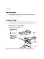
&-.
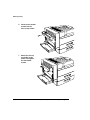
The face-up tray enables you to print to the side exit of the printer. Your documents
are stacked in the tray with the first page facing up. There are two ways to install the
face-up tray: without a duplexer installed or with a duplexer installed on the printer.
!"#
1
2
Unpack the face-up
tray and find these
parts:
Face-up tray
Thumbscrews
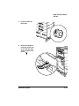
Attach the connecting plate to the
printer, using the two
thumbscrews.
%#&!#
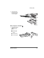
3
Firmly attach the
face-up tray to the
connecting plate
!"#
1
Unpack the face-up
tray and find its
parts:
Face-up tray
Face-up tray
holder
Thumbscrews
Cutter/supporter
'#(#
%#&!#
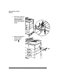
2
Holding the supplied
cutter/supporter
sideways, insert it
into any one of the
three connecting
parts on the lower
end of the filler
panel.
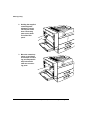
3
Move the cutter/supporter up and down
to break the connecting part. Repeat this
step to break the
other two connecting parts.
%#&!#
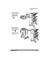
4
Lift up the filler panel
as shown to remove
it from the printer.
5
Insert the cutter/supporter into the slots
at the front end of the
duplexer. It is used to
support the face-up
tray.
'#(#
)
%#&!#
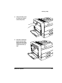
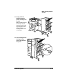
6
Insert the two thumbscrews into the
face-up tray holder.
7
Attach the face-up
tray holder to the
printer and tighten
the two thumbscrews.
%#&!#
8
Attach the face-up
tray onto the holder.
'#(#
*
+$,
+
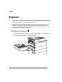
The duplexer enables you to print your documents using both the front and back sides
of the paper. The duplexer interrupts the normal route of the paper path and flips the
paper over to feed it back for printing on the back side.
»
Note: If you are installing the duplexer to the base model printer with the minimum
memory, we suggest you upgrade your printer’s memory so that duplexing can
operate efficiently with your printer. See “Single In-Line Memory Modules,” chapter 3,
for instructions on adding printer memory.
-
1
Unpack the duplexer and make sure the multipurpose tray is folded down.
2
Hook the duplexer into the slots of the feeder.
+$,
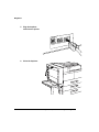
3
Firmly insert the
stopper on the right
side of the duplexer
into the printer.
4
Secure the duplexer
by hooking the safety
wire to the printer.
'#(#
.
+$,
5
Plug the duplexer
cable into the printer.
6
Close the duplexer.
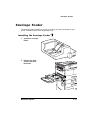
/$%
%(&
The envelope feeder enables you to print on a variety of sizes of envelopes on your
printer. It installs in place of the multipurpose tray.
1
Unpack the envelope
feeder.
2
Remove the multipurpose tray from
the printer.
'#(#
/$%
3
Note: Make sure the
two stubs on the
feeder go securely into
the slots on the printer.
»
Holding the envelope feeder horizontally, attach it to the
printer.
4
Lift the envelope
stopper, and insert
an envelope stack
with the flap up and
the long edge first.
5
Slide the side guide
in so it lightly
touches the edge of
the envelope stack.
'0"##
%1'%2
!"-
&/&0
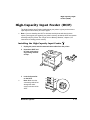
The High-Capacity Input Feeder installs below your printer. It gives you three more
input trays to load a variety of sizes of paper.
»
Note: If you are installing the HCIF to the base model printer with the minimum
memory, we suggest you upgrade your printer’s memory so that the HCIF can operate
efficiently with your printer. See “Single In-Line Memory Modules,” chapter 3, for
instructions on adding printer memory.
»
1
Unplug the power and the communication cables from the printer.
2
Unpack the HCIF and
its parts, and remove
any packing material
or tape.
3
Lock the front roller
on the HCIF.
Note: Make sure the
connecting cable is fed
through the cable
notch on the rear of the
HCIF.
'#(#
'0"##
%1'%2
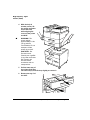
4
With the help of
another person, lift
the printer and lower
it onto the HCIF,
while aligning the
covers of the printer
and HCIF.
WARNING! The
printer weighs
approximately 91 lbs
(41 kg) without
consumables. Do not
attempt to lift the
printer by yourself.
ACHTUNG! Der
Drucker hat ein
Gewicht von ungefähr
41 kg. Bitte versuchen
Sie niemals, den
Drucker alleine
anzuheben oder zu
transportieren.
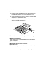
5
Pull the lower tray of
the printer all the way
out until it stops, then lift it up slightly to remove it.
6
Remove the tray 5 of
the HCIF.
Printer
Lower
Tray
HCIF
Tray 5
'0"##
%1'%2
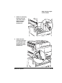
7
Attach one mounting
bracket to the left
side of the printer/
HCIF frame and
secure it with a
thumbscrew.
8
Attach the other
mounting bracket to
the right side of the
printer/HCIF frame,
and secure it with a
thumbscrew.
'#(#
)
'0"##
%1'%2
9
Insert the trays back
into the printer and
HCIF.
10 Plug the connecting
cable from the HCIF
into the rear of the
printer.
'0"##
#3
!"-
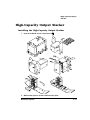
1
Unpack the HCOS and its components.
2
With another person, lift the HCOS from the pallet.
'#(#
*
'0"##
#3
3
Check for these components included in
the shipping
box:
Vertical Transport
Note: Check also for
an alignment bracket.
»
Locking Bar
HCOS
4
-
Install the vertical
transport onto the
top of the
printer.
'0"##
#3
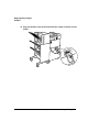
5
Lock the rollers on
the printer.
6
Pass the locking bar
under the printer and
hook it into the slots
on the left side of the
printer.
'#(#
.
'0"##
#3
7
Push up the supporting unit on the locking bar to firmly
secure it between the
printer cover and the
printer.
8
Attach the alignment
bracket with the
screws to the
printer.
'0"##
#3
9
Raise the horizontal
transport, then flip
down the two supporters so that it
remains horizontal.
10 Move the HCOS
close enough to the
printer for cable connection.
»
Note: Make sure the
HCOS and the printer
align correctly.
'#(#
'0"##
#3
11 Plug the power cable
of the HCOS into the
connector on the
side of the printer.
12 Insert the end of the
locking bar into the
opening on the bottom of the HCOS.
'0"##
#3
13 Gently push the
HCOS toward the
printer until they lock
in place.
Make sure the horizontal transport is positioned correctly on the
top of the printer and
its far end goes
securely into the vertical transport.
14 Insert and tighten the
locking screw to
secure the HCOS to
the printer.
'#(#
'0"##
#3
15 Plug the interface cable of the HCOS into the output connector on the
printer.
4
1
A security key is available to password-protect the Operator Control and the Administration menus. When the security key is installed, the Installation menu appears in the
printer’s configuration menu.
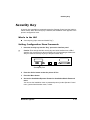
!"#
A security key (9-pin connector labeled “Key”)
$%&'
1
▲
Insert the security key into the “Key” port on the interface panel.
Caution: Even though both the security key and serial interface have a DB-9
interface, the connectors are keyed, and they can’t be interchanged. Make sure
that you install the security key only in the port marked “Key.”
Security Key Port
2
Press the Online button to take the printer off line.
3
Press the Menu button.
4
Access the Installation/Operator Passwrd or Installation/Admin Password
menu.
You can use the Installation menu to password-protect just the Operator Control
menu, just the Administration menu, or both.
'#(#
)
4
5
Select the password(s).
Note: Keep in mind that the password(s) you select also protect the Admin mode
of Remote Console, available through QMS CrownAdmin or a telnet session.
»
Menu
Installation/Operator Passwrd
Installation/Admin Password
Choices
Up to 16 characters (any letter, number, or symbol)
Default
Blank (no password)
Notes
Passwords are case sensitive and are entered as an alphanumeric string.
If you choose a password that is not 16 characters long, press the Select
button until you get to the rightmost character of the password field. Enter
the password character string the same as you would enter an
alphanumeric string. See chapter 2, “Printer Configuration” in the
Reference for complete information on how to enter alphanumeric
characters.
6
Enable the password(s).
Menu
Installation/Use Operator Pwd
Installation/Use Admin Pwd
Choices
On—Requires the correct password to access to the Administration and/
or Operator Control menus.
Off—Does not require a password to access the Administration and/or
Operator Control menus.
Default
Off
Notes
Enter the passwords in the Installation/Operator Passwrd and Installation/
Admin Password menus.
7
Save your changes and exit from the configuration menu.
8
Remove the security key, and store it in a secure location.
After you exit from the menu and remove the security key, the Installation menu is
removed from the control panel message window.
9
Press the Online button to put the printer back on line.
4
$%&'
Once a menu is password protected, you can’t enter the menu or make changes in it
until you enter a valid password.
»
Note: Password protection does not prevent software commands from changing
functions.
If a password is required to enter the Operator Control or Administration menu,
the message window displays
ENTER PASSWORD
when you use the Select button to enter the menu. Enter the password, or press
the Menu button to return to the previous menu.
If you enter an invalid password, the message window flashes
INVALID PASSWORD
for three seconds and then returns you to the configuration menu.
If you forget the password, repeat the procedure in “Setting Configuration Menu
Passwords” on page 2-25.
'#(#
*
5665,7
2332+4
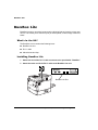
BuzzBox Lite warns you with a buzzer and/or a blinking light any time the printer goes
off line. This means you’re alerted to print job interruptions, such as empty media cassettes.
!"#
The BuzzBox Lite kit contains the following items:
BuzzBox Lite unit
RJ-11 cable
Adhesive-backed clips
())(*
1
Attach one end of the RJ-11 cable connector to the port labeled “BuzzBox.”
2
Attach the other end of the RJ-11 cable to the BuzzBox Lite unit.
BuzzBox Lite Port
-
5665,7
3
Choose a location to mount the BuzzBox Lite unit.
Ensure that the unit does not
4
interfere with paper exiting the printer.
cover any vents, doors, connectors, or labels.
cause the BuzzBox ribbon cable to stretch or twist.
Use the adhesive-backed clips provided to mount the BuzzBox Lite unit
where the printer operator can see and/or hear it.
We’ve provided a cable, but you can use up to a 500-foot cable (RJ-11 4-pin or
6-pin).
5
To test the BuzzBox Lite, make sure its switches are on, then press the
printer’s Online button to take the printer off line.
Note: You can use the BuzzBox switches to enable or disable the buzzer, the
light, or both.
»
When the printer goes off line, the light flashes and the buzzer sounds until the
printer is placed back on line or until the light and buzzer switches are turned off.
())(*
When the BuzzBox lights or buzzes, check the printer message window to find out
what has interrupted printing. See chapter 5, “Troubleshooting Printer Problems,”
in the Operations manual for a list of printer messages and how to respond to
them.
'#(#
.
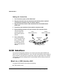
*-55
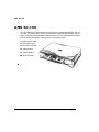
You can expand your QMS 3260/4032 Print System by adding the QMS SC-100 digital copier. The copier option can be connected to the standard parallel port on your
printer. Check the documentation included with your SC-100 digital copier for instructions on setup, configuration, and operation of the copier option.
Included with the QMS
SC-100 digital copier:
Software CD-ROM
Parallel cable
Power adapter
Documentation
!"#
$
"
" , , ,
“Introduction” on page 3-2
“Anti-Static Protection” on page 3-2
“Single In-Line Memory Modules” on page 3-2
“Time-of-Day (TOD) Clock” on page 3-5
“Updating System Software” on page 3-8
This chapter provides details on how to install memory SIMMs, time-of-day (TOD)
clock, and how to update system software.
)
-
6
▲ Caution: It's very important to protect the printer controller board and any associated
daughterboard or module from electrostatic damage while performing any task
involving the controller board.
If an anti-static wrist strap is provided in your printer option kit, attach one end of it
to your wrist and the other end to any convenient electrical ground (for example, the
bare metal chassis of equipment, as on the back of a computer). Never attach the
wrist strap to any piece of equipment with an electrical current present. Turn off all
power switches first. Plastic, rubber, wood, painted metal surfaces, and telephones
are not acceptable grounding points.
If you don't have an anti-static wrist strap, discharge your body's static electric
charge by touching a grounded surface before you handle any printer boards or
components and before removing the controller board. Also avoid walking around
after grounding yourself.
!-4
Single in-line memory modules (or SIMMs) are compact circuit boards with surface-mount memory chips. They are used for the printer’s read/write or RAM memory.
Your QMS 3260/4032 Print System includes the following printer memory:
QMS 3260/4032 Print System —16 MB RAM
QMS 3260/4032 EX Print System—32 MB RAM
QMS 3260/4032 ImageServer Print System—32 MB RAM
0$7
$
However, you can upgrade either of these models to a maximum of 384 MB of RAM
through the installation of additional SIMMs.
Additional memory allows you to download more fonts and increase the printer's
buffer (area where data sent from the computer is stored while waiting to be printed).
▲ Caution: You may also need additional memory to print on some media sizes at
resolutions above 600x600 dpi. Refer to chapter 3, “Advanced Printing Features,” in
the Operation manual for details.
&
▲ Caution: It's very important to protect the printer controller board and SIMM from
electrostatic damage. Before performing this procedure, review the anti-static caution
in “Anti-Static Protection” on page 3-2.
Always handle circuit boards by the edges only.
1
In case you need to restore any memory settings after the SIMM installation,
print an advanced status page.
Note: Installing SIMMs automatically resets memory defaults. If your memory
settings are specific to your environment, print an advanced status page before
installing SIMMs, so you can recover the current memory settings.
»
2
Turn off the printer, and then disconnect the power cord and all interface
cables from the printer.
3
Remove the printer’s controller board.
Loosen two screws, one on each end of the I/O connector panel, and, using the
tab on the connector panel, pull the controller board from the printer.
4
Position the controller board on a flat surface so the controller board lies
flat and the I/O connector panel is facing you.
8!+$38#9(#
0$7
$
5
If you need to remove a SIMM
before installing one, remove it as
follows; otherwise go to step 6.
Note: If all the SIMM connectors are
filled and you want to install more
memory, you have to exchange one
or more SIMMs for SIMMs with a
greater memory capacity.
»
a
Using your thumbs, pull the
latches (one on each side of the
SIMM connector) outward.
b
Tilt the SIMM backwards to a
45° angle away from the SIMM
connector.
c
Lift the SIMM out.
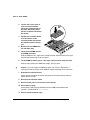
6
Remove the new SIMM from its anti-static bag.
7
Insert the new SIMM into the
SIMM connector.
a
»
......
............
............
............
............
............
............
............
............
Hold the SIMM at a 45° angle
to the controller board, with the
notch on the right side and the
bottom edge in the connector.
Note: You can insert a SIMM in
any SIMM connector as long
as DRAM0 and the SIMM
connector before the one
you’re installing are occupied.
......
............
............
............
............
............
............
............
............
!9+#1!+2
$3
b
Tilt the SIMM up to a 90° angle until you feel it snap into place.
When seated, the SIMM stands
upright, firmly in place. If you
cannot snap the SIMM into place,
do not force it. Reposition it, making sure that the bottom of the
SIMM is seated completely in the
connector.
8
9
Repeat steps 6–7 for each additional SIMM being installing.
Reinstall the controller board into
the printer.
......
............
............
............
............
............
............
............
..
..
..
..
....
Gently slide the controller board into
the printer until it is fully seated, and
then tighten the two screws.
10 Reconnect all interface cables.
11 Reconnect the power cord, and turn on the printer.
12 Print a start-up page.
Check that the start-up page states the total size of the RAM installed in your
printer.
13 If necessary, refer to the advanced status page you printed in step 1 to
reconfigure printer memory.
--/0
The time-of-day clock provides time and date information on the
startup page and in the accounting data.
!"#
The optional time-of-day clock kit includes only the following:
Time-of-day clock
8!+$38#9(#
)
!9+#1!+2
$3
&
Caution: It's very important to protect the printer controller board and any associated
circuit boards from electrostatic damage. Before performing this procedure, review the
antistatic caution in “Anti-Static Protection” on page 3-2. In addition, always handle
circuit boards by the edges only.
1
Turn off the printer, and then disconnect the power cord and all interface
cables from the printer.
2
Loosen two screws (one on each end of the interface panel) and, using the
tab on the panel, pull the controller board from the printer.
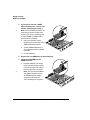
3
Attach the time-of-day clock to the controller board.
WARNING: Because the time-of-day clock includes an internal battery, there is a
danger of explosion if the clock is incorrectly installed or replaced. Replace it only
with a similar QMS time-of-day clock. Dispose of any used time-of-day clock in
accordance with local laws and regulations.
ACHTUNG! Da der Uhrenbaustein eine interne Batterie enthält, besteht
Explosionsgefahr, falls dieser falsch eingesetzt oder ersetzt wird. Er darf nur
durch einen Baustein gleichen Typs ersetzt werden. Bitte entsorgen Sie den
Baustein gemäß den geltenden Entsorgungsbestimmungen.
AVERTISSEMENT! Dû au fait que l’horloge interne de l’imprimante est munie
d’une batterie interne, il y a un risque d’explosion si celle-ci est mal installée ou
remplacée. La remplacer seulement avec une horloge similaire à l’horloge interne
QMS. Se départir de toute horloge interne défectueuse en respectant les lois et
réglementations en vigueur.
!9+#1!+2
$3
a
b
Locate the
time-of-day clock
socket on the
controller board
and the pin 1 notch
or printed label.
Locate the pin 1
indicator mark on
the top of the
time-of-day clock.
This mark may be
a notch or a slight
depression on one
end of the clock.
Pin 1 Indicator Mark
Pin 1 Notch/Label
..........
............
............
............
............
............
..
..
..
..
............
............
c
Align this indicator mark with the pin 1 notch or printed label on the controller
board.
d
Gently press down on the time-of-day clock until it’s firmly seated.
Caution: Make sure that the pins on the time-of-day clock are properly
aligned with those in the receiving socket on the controller board. Damage to
the time-of-day clock and/or controller board could result if the pins are
misaligned.
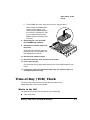
4
Reinstall the controller board.
Gently slide the controller board into the printer until it is fully seated, and then
tighten the two screws.
5
Reconnect all interface cables.
6
Reconnect the power cord and turn on the printer.
7
Print a startup page.
Check that the time-of-day clock is listed under “options” on the startup page.
8!+$38#9(#
*
�
9(#
.
!
The system software in your QMS 3260/4032 Print System is stored in flash ROM,
read-only memory that can be erased and rewritten to “in a flash.” Updated system
software allows you to take advantage of future enhancements to the printer.
Updating the system software can be a real advantage for keeping your printer at the
level of the latest release. As your printer ages QMS will periodically add enhancements to the system software to correct problems detected by our customers. Reloading the system software can also be a method of troubleshooting your printer when it
has stopped working. See “Troubleshooting Printer Problems,” in the Operations manual for information on downloading system software to a non-working printer.
Contact QMS or your QMS vendor for information on obtaining new system software.
See appendix A, “QMS Customer Support,” for locations and telephone numbers.
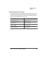
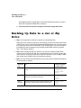
%++,-+
Downloading
via...
Host hard disk
space required
Notes
Parallel
1.5 MB
Recommended method for downloading from a
non-networked computer.
No additional cables or changes of port settings
required.
Serial
1.5 MB
For use when the parallel method is unavailable.
Requires either a null modem cable or a
standard serial cable with a null modem adaptor
attached.
Ethernet
1.5 MB
Requires a 10BaseT/100BaseTX connection to
the printer’s resident network interface or a
connection to the optional network interface.
&
'
Depending on the media that your new system software is delivered to you, the procedure for sending the system software to the printer is basically the same as printing a
document. You can download the system software from the QMS website after con-
�
9(#
tacting our Customer Response Center, or the system software can be shipped to you
on CD-ROM or diskettes. If you get diskettes use the following procedure to unzip the
system software on the diskettes using a PC.
Make sure that you have a copy of the advanced status page from your printer so that
you can restore settings after updating the system software.
$%
$
»
Note: It is not necessary to decompress the system software if you downloaded it
from the QMS website or received it on CD-ROM.
1
Switch to the MS-DOS prompt.
2
Create a new directory on your PC. Type
X:\mkdir newdir↵
where newdir refers to the name of the new directory where your system software
will be stored and X: is the hard drive designation.
3
Change to this directory. Type
X:\cd newdir
4
Insert the printer system software disk in your PC’s 3.5" disk drive.
5
Type
X:\pkunzip x:\system↵
where X is the name of the disk drive in which you inserted the system software
disk.
6
Follow the prompts.
They instruct you to insert the system software disks in the following order:
a
Last disk (system software disk 3)
b
Disk 1 (system software disk 1)
c
Disk 2 (system software disk 2)
d
Disk 3 (system software disk 3)
8!+$38#9(#
.
�
9(#
&
—&—&..
%!
$%
—
!!!
1
Send the new system image to the printer.
Type
copy /b filename.ps lpt#↵
where filename refers to the name of the system software file (systemdl.ps is
a typical name) and # is the number of the parallel port (/b refers to binary
files.)
2
While the system software is loading, the Online LED blinks off and on, and
the message window displays
Downloading image
via parallel port.
3
After the new system software has been written to ROM, the printer returns
to IDLE.
Note: The new system image doesn’t erase the old image until the printer verifies
that the new image is valid.
»
4
Restart the printer to activate the new system software.
5
Print another advanced status page, and verify that the configuration settings are the same.
%!
$%
—
!
1
Connect the serial cable to the printer.
2
Set the PC’s baud rate to 38400 by typing
mode com # 38400 n 8 ↵
(where # is the serial communications port 1 to 4).
3
Access the Administration/Communication/Serial menu on your printer, set
the Hardware Flow Control RTS and CTS values to On, the baud rate to
38400, press the Online or Menu key, and then select yes to Save Changes.
4
Type
copy /b filename.ps com#↵
�
9(#
where filename refers to the name of the system software file (systemdl.ps is a
typical name) and # is the number of the serial port on the PC (/b refers to binary
files.)
The Downloading process takes about 15 minutes depending on the size of the
file and the speed of your computer. The Ready LED blinks as the new system
image is copied to the printer.
5
While the system software is loading, the Online LED blinks off and on, and
the message window displays
Downloading image
via serial port.
6
After the new system software has been written to ROM, the printer returns
to IDLE.
Note: The new system image doesn’t erase the old image until the printer verifies
that the new image is valid.
»
7
Restart the printer to activate the new system software.
8
Print another advanced status page, and verify that the configuration settings are the same.
%!
$%
—&
1
Open an ftp session at your PC or workstation by typing one of the following commands:
ftp printername↵
ftp ipaddress↵
2
(for example, ftp pctdev6↵)
(for example, ftp 161.33.130.45↵)
When prompted for a user name and password, press Enter.
An ftp> prompt displays.
3
At the ftp> prompt, change to binary mode by typing
bin↵
4
At the ftp> prompt, send the system software file to the printer’s hard disk
by typing
put filename.ps↵
where filename refers to the name of the system software file (systemdl.ps is a
typical name).
8!+$38#9(#
�
9(#
5
6
While the system software is loading, the Online LED blinks off and on, and
the message window displays
Downloading image
At the ftp> prompt, end the ftp session by typing
quit↵
7
When the Online LED stops flashing and the printer’s message window
reads Idle for at least 30 seconds, turn the printer off and then on again.
8
Restart the printer to activate the new system software.
9
Print another advanced status page, and verify that the configuration settings are the same.
Note: The system software can also be downloaded using CrownAdmin software
utilities if you have CrownAdmin installed and you are familiar with it.
»
&
—%
%!
$%
—&
1
Note: If you don’t have CrownAdmin installed use the QMS Software Utilities
CD-ROM to install it.
»
Start CrownAdmin Software Utilities on you Macintosh.
2
Select the printer from the printer list area.
3
From the File menu, select Print.
4
In the Print File window, select Browse.
5
Select the new system software file where it is stored (on CD-ROM or on
your hard disk.)
6
Click Print.
7
When the Online LED stops flashing and the printer’s message window
reads Idle for at least 30 seconds, turn the printer off and then on again.
8
Restart the printer to activate the new system software.
9
Print another advanced status page, and verify that the configuration settings are the same.
�
9(#
+'&
The following error pages print if downloading the system software was unsuccessful.
The possible problems listed may give you an idea as to what went wrong with the
download. Each error page lists one of the following two-line messages, the name of
the product, and the upgrade system release number.
Error Message
Possible Problem
Unable to replace FLASH image
due to insufficient memory!
The system cannot use 16 MB—you need
to add more memory.
Unable to reprogram FLASH due to error in
image contents!
Error detected in file or it did not understand
the file—try to resend.
Unable to reprogram FLASH due to inability
to locate imagefile!
Possibly a low memory error—you need to
add more memory.
Unable to replace FLASH image due to
product uncompatibility!
Wrong system code sent—possibly for
another QMS printer.
8!+$38#9(#
$
!%&'
"
",,,
“Introduction” on page 4-2
“Anti-Static Protection” on page 4-2
“Network and LocalTalk Interfaces” on page 4-2
“SCSI Interface” on page 4-6
The following options mount on your printer’s controller board:
Network interfaces (CrownNet 10BaseT/100BaseTX, CrownNet Token-Ring, and
DECnet-TCP/IP)
LocalTalk interface
SCSI interface
)
-
6
▲ Caution: It's very important to protect the printer controller board and any associated
daughterboard or module from electrostatic damage while performing any task
involving the controller board.
If an anti-static wrist strap is provided in your printer option kit, attach one end of it
to your wrist and the other end to any convenient electrical ground (for example, the
bare metal chassis of equipment, as on the back of a computer). Never attach the
wrist strap to any piece of equipment with an electrical current present. Turn off all
power switches first. Plastic, rubber, wood, painted metal surfaces, and telephones
are not acceptable grounding points.
If you don't have an anti-static wrist strap, discharge your body's static electric
charge by touching a grounded surface before you handle any printer boards or
components and before removing the controller board. Also avoid walking around
after grounding yourself.
74
Your printer supports the following interface cards:
CrownNet 10BaseT/100BaseTX (TCP/IP, NetWare, EtherTalk, LAN Manager/LAN
Server) for an additional CrownNet 10BaseT/100BaseTX connection
:(3#
7#$!#$39#
CrownNet Token-Ring (TCP/IP, NetWare, LAN Manager/LAN Server)
DECnet-TCP/IP
LocalTalk
You can install one of these interface cards in addition to the three standard interfaces—parallel, serial, and CrownNet 10BaseT/100BaseTX (TCP/IP, NetWare, EtherTalk, LAN Manager/LAN Server). The printer’s Simultaneous Interface Operation
(SIO) allows all of these interfaces to be active at the same time. In other words, your
printer can simultaneously communicate through all four ports with four hosts, either
computers or networks.
!$
"#
An optional interface kit includes the following:
An interface card
Interface documentation (in hardcopy and/or on CD-ROM)
The kit may also include additional parts not required for network interface installation
on this printer.
&
▲ Caution: It's very important to protect the printer controller board and any associated
circuit boards from electrostatic damage. Before performing this procedure, review the
anti-static caution in “Anti-Static Protection” on page 4-2. In addition, always handle
circuit boards by the edges only.
1
Turn off the printer, and then disconnect the power cord and all interface
cables from the printer.
2
Loosen two screws (one on each end of the interface panel) and, using the
tab on the side of the panel, pull the controller board from the printer.
3
Remove the two screws holding the metal plate over the optional interface
opening.
The optional interface opening is labelled “Option.” It’s located next to the “Parallel” port. Save the two screws. (You’ll use them when you install the optional interface card.) You can discard the plate.
9##+#0" #
:(3#
7#$!#$39#
4
▲
Attach the interface card to the controller board.
a
Position the interface card so that its I/O connector slides into its opening in
the interface panel and that its 80-pin connector aligns with the 80-pin
connector on the controller board.
b
Gently press the interface card down until its connector is fully seated and the
card is secured by the plastic support post(s).
Caution: Make sure that the connectors on the interface card and controller
board are properly aligned. Damage to the interface card and/or controller
board could result if the pins are misaligned.
..
............
............
............
............
............
..
..
..
..........
............
............
5
Secure the interface card to the interface panel with the two screws you
removed earlier.
6
Reinstall the controller board.
Gently slide the controller board into the printer until it is fully seated, and then
tighten the two screws.
7
Reconnect all interface cables.
8
Reconnect the power cord, and turn on the printer.
9
Print a start-up page.
Check that the start-up page lists the interface just installed under “Options.”
:(3#
7#$!#$39#
/'$
Once a network interface is installed, refer to the following for more information:
For a CrownNet interface, refer to the QMS CrownNet Setup Guide for information
on connecting to the network, installing the software, and configuring the interface
and the network. In addition, chapter 2, “Printer Configuration,” of QMS CrownNet
System Administrator’s Guide, provides complete configuration information.
For a DECnet-TCP/IP interface, refer to the QMS DECnet-TCP/IP Setup Guide and
the TCP/IP Protocol Option User’s Guide.
Your application and network documentation contain information on printing over
the network.
*
$
Once a LocalTalk interface is installed, refer to the following for more information:
For configuration information, refer to chapter 2, “Printer Configuration,” in the
Reference manual.
Your application and Macintosh documentation contain information on printing via
LocalTalk.
' $
Interface cables are not included with your printer. If you’re replacing a printer, you
may already have the necessary cables. If not, you’ll need to purchase the cables
from your QMS vendor or a local computer store.
To connect your printer to a single Macintosh, you must have
An optional LocalTalk interface.
Two PhoneNET-type transformer boxes: one with a DIN-8 connector for the
printer port and one with a DIN-8 connector for the Macintosh port
An RJ11 (telephone) cable
Two terminating resistors to close the open sockets left in the transformer boxes
after the connection is made
If you’re connecting the printer to an AppleTalk network with more than one Macintosh, see your PhoneNET and Macintosh documentation for more information.
9##+#0" #
)
9#
(
1
Turn off both the printer and the Macintosh.
2
Plug the connector from one transformer box into the printer’s optional
LocalTalk port (installed in the slot marked “Option”).
3
Plug the connector from the other transformer box into the Macintosh
printer port.
4
Connect the two transformer boxes with the telephone cable.
5
Put terminating resistors in all open sockets in the connector boxes.
This ensures proper
communication and
helps speed up transmission.
6
Host
DIN-8 Female Port
Printer
DIN-8 Female Port
Turn on the printer.
Transformer
Boxes
A start-up page should
print. If it doesn’t, refer
to chapter 5, “Troubleshooting Printer Problems,” of the Operation
manual.
RJ-11 Cable
Terminating Resistors
The optional SCSI interface allows you to connect up to three optional SCSI hard
disks or up to two SCSI hard disks or a Jaz or Zip disk. Hard disks provide storage for
fonts, emulations, and other files, increase the number of pages that can be collated,
and provide a secondary storage area for spooled data, while providing virtual memory capabilities.
!$
"#
An optional SCSI interface kit includes the following:
SCSI interface card
9#
SCSI interface card ribbon cable
Connector face plate
Two larger screws
Two smaller screws
&
▲ Caution: It's very important to protect the printer controller board and any associated
circuit boards from electrostatic damage. Before performing this procedure, review the
anti-static caution in “Anti-Static Protection” on page 4-2. In addition, always handle
circuit boards by the edges only.
1
Turn off the printer, and then disconnect the power cord and all interface
cables from the printer.
2
Loosen two screws (one on each end of the interface panel) and, using the
tab on the side of the panel, pull the controller board from the printer.
3
Remove the two screws holding the metal plate over the SCSI interface
opening.
The SCSI interface opening is labelled “SCSI.”
You can discard the metal plate and screws.
4
Attach the ribbon cable
to its connector on the
SCSI interface card.
5
Attach the SCSI interface card to the controller board.
a
Position the SCSI
interface card so that
its ribbon cable
connector aligns with
the SCSI connector
on the controller
board.
9##+#0" #
...
.... ..
.... ....
.... ....
............
......
............
............
............
............
............
............
............
..
..
..
......
...
.... ..
.... ....
.... ....
............
*
9#
b
▲
Gently press the ribbon cable connector down until it’s fully seated.
Caution: Make sure that the connectors on the ribbon cable and the
controller board are properly aligned. Damage to the controller board could
result if the pins are misaligned.
6
c
Insert the SCSI interface card connector into its opening in the interface
panel.
d
Secure the SCSI interface card to the interface panel with the two larger
screws in the kit.
Reinstall the controller board.
Gently slide the controller board into the printer until it’s fully seated, and then
tighten the two screws.
7
Reconnect all interface cables.
8
Reconnect the power cord and turn on the printer.
9
Print a start-up page.
Check that the start-up page lists the interface just installed under “Options.”
-
(")
&$
"
",,,
“Introduction” on page 5-2
“Emulations” on page 5-3
“Disk Fonts” on page 5-6
“PCL 5e Font SIMMs” on page 5-7
“Kanji Font Internal IDE Hard Disk” on page 5-10
“QFORM” on page 5-14
Your printer has several software options which expand its capabilities:
QMS emulations
QMS ProCollection disk fonts
QMS ProCollection font SIMM
QMS Intellifont font SIMM
QMS Kanji font internal hard disk
QMS ImageServer
QMS QFORM
0
&
▲ Caution: It's very important to protect the printer controller board and any associated
daughterboard or module from electrostatic damage while performing any task
involving the controller board.
If an anti-static wrist strap is provided in your printer option kit, attach one end of it
to your wrist and the other end to any convenient electrical ground (for example, the
bare metal chassis of equipment, as on the back of a computer,). Never attach the
wrist strap to any piece of equipment with an electrical current present. Turn off all
power switches first. Plastic, rubber, wood, painted metal surfaces, and telephones
are not acceptable grounding points.
If you don't have an anti-static wrist strap, discharge your body's static electric
charge by touching a grounded surface before you handle any printer boards or
components and before removing the controller board. Also avoid walking around
after grounding yourself.
)
/$#
%
Optional emulations, such as CGM, LN03 Plus, and XES/UDK, are available as PostScript files on floppy disks. This section describes how to download an optional emulation to the printer’s hard disk.
»
Note: You must have at least one hard disk, internal or external, attached to the
printer in order to use an optional emulation. If more than one hard disk is available,
the emulation automatically installs itself on the disk with the most free storage space.
QMS recommends that you have at least 4 MB of memory above the base
configuration and that you add at least 1 MB memory to each emulation installed. This
ensures that the printer can run the emulation without slowing down performance.
'+
)
!
!!!*$
1
Turn on the printer, and wait for IDLE to appear in the message window.
2
Insert the emulation disk in your computer’s 3.5" disk drive, and change to
that drive (for example, if you’re using the A drive, type a:↵).
3
Send the emulation to the printer’s hard disk.
If your computer and printer are connected through the parallel port, type
copy /b *.ps lpt#↵
where # is 1 to 3. (/b refers to binary files.)
If your computer and printer are connected through the serial port, type
copy /b *.ps com#↵
where # is 1 to 4. (/b refers to binary files.)
4
When downloading is complete, reboot the printer.
The emulation should be listed in the Options section of the printer’s start-up
page, in the Administration/Emulation printer’s configuration menu, and on the
advanced status page.
/$#8%8#"9(#
)
/$#
)
&*$
»
Note: Before you begin this procedure, your printer and computer (or UNIX
workstation) must be connected to an Ethernet network running TCP/IP and have
valid IP addresses.
1
If your computer is running Windows, change to DOS.
2
Insert the emulation disk in your computer’s 3.5" disk drive, and change to
that drive (for example, if you’re using the A drive, type a:↵).
3
If you want to download the emulation from a UNIX workstation, copy the
installation file from your computer to a temporary directory on your
workstation.
4
Turn on the printer, and wait for IDLE to appear in the message window.
5
Open an ftp session at your computer or workstation by typing one of the
following commands:
ftp printername↵
ftp ipaddress↵
6
(for example, ftp pctdev6↵)
(for example, ftp 161.33.130.45↵)
When prompted for a user name and password, press Enter.
An ftp> prompt displays.
7
At the ftp> prompt, change to binary mode by typing
bin↵
8
At the ftp> prompt, send the emulation file to the printer’s hard disk by
typing
put filename.ps↵
where filename is the name of the installation file.
The printer’s message window reads 1 Active Job, and the Disk light flashes
to indicate that the emulation is being downloaded to the hard disk. The ftp>
prompt returns when the emulation has finished loading.
9
At the ftp> prompt, end the ftp session by typing
quit↵
10 When the Disk light stops flashing and the printer’s message window reads
Idle for at least 30 seconds, turn the printer off and then on again.
)
/$#
11 When the printer’s message window reads Idle again, the emulation is
ready to use.
The emulation should be listed in the Options section of the printer’s start-up
page, in the Administration/Emulation printer’s configuration menu, and on the
advanced status page.
»
Note: You may want to erase any installation files left on your computer (and/or
workstation), and then remove any temporary directories.
+
Refer to the documentation that came with your emulation for configuration and usage
instructions.
/$#8%8#"9(#
))
+3%
&
Optional fonts, such as the 65 ProCollection fonts for the HP emulations on your
printer and other special PostScript fonts, are available as PostScript files on floppy
disks. This section describes how to download optional fonts from a floppy disk to the
printer’s hard disk.
»
Note: At least one hard disk (internal or external) must be present on your printer
before you can download a font. If more than one hard disk is available, the font
automatically installs itself on the disk with the most free storage space.
%!
+
This procedure contains the instructions for downloading the fonts from a floppy disk
onto your printer’s hard disk.
1
Connect the computer to the printer’s parallel or serial port.
2
Turn on the printer, and wait for IDLE to appear in the message window.
3
Insert the font disk in your computer’s 3.5" disk drive, and change to that
drive (for example, if you’re using the A drive, type a:↵).
4
Send the fonts to the printer’s hard disk.
If your computer and printer are connected through the parallel port, type
copy /b *.ps lpt#↵
where # is 1 to 3. (/b refers to binary files.)
If your computer and printer are connected through the serial port, type
copy /b *.ps com#↵
where # is 1 to 4. (/b refers to binary files.)
5
)
When the downloading is complete, reboot the printer.
7)%
64$&
The QMS 3260/4032 supports these PCL 5e font SIMMs: the QMS ProCollection font
SIMM and the QMS Intellifont font SIMM. The QMS ProCollection SIMM contains 65
fonts. The QMS Intellifont SIMM contains 17 fonts.
&*1%%
▲ Caution: It's very important to protect the printer controller board and SIMM from
electrostatic damage. Before performing this procedure, review the anti-static caution
in “Anti-Static Protection” on page 5-2. In addition, always handle circuit boards by the
edges only.
1
Turn off the printer, and then disconnect the power cord and all
interface cables from the printer.
......
............
............
............
............
............
............
............
............
/$#8%8#"9(#
)*
7)%
2
Loosen two screws (one on
each end of the interface
panel) and, using the tab on
the lower side of the panel,
pull the controller board from
the printer.
3
Position the controller board
on a flat surface so the
controller board lies flat and
the interface panel is facing
you.
4
Remove the font SIMM from
the anti-static bag.
5
Insert the font SIMM into the
font SIMM connector.
......
............
............
............
............
............
............
............
..
..
..
..
....
Hold the SIMM at a 45° angle to the controller board, with the notch on the right
side and the bottom edge in the connector.
6
Tilt the SIMM up toward you to a 90° angle until you feel it snap into place.
When properly seated, the SIMM sits upright, firmly in place.
▲
Caution: If you can’t snap the SIMM into place, don’t force it. Reposition it,
making sure that the bottom of the SIMM is seated completely in the connector.
7
Reinstall the controller board.
Gently slide the controller board into the printer until it’s fully seated, and then
tighten the two screws.
8
Reconnect all interface cables.
9
Reconnect the power cord and turn on the printer.
10 Print a start-up page.
Check that the start-up page indicates the font SIMM just installed under
“Options.” It’s identified as cartridge2%.
11 Print an advanced status page.
)-
7)%
a
Using the Administration/Special Pages/Status Page Type menu, change the
status page type to Advanced.
b
Using the Administration/Special Pages/Print Status menu, print the status
page.
The list of HP PCL fonts includes all of the new fonts. Keep this status page
for reference when accessing these fonts.
12 Ensure that the Administration/Memory/Disk Cache memory client is set to
at least 20 KB.
0
After you install the font SIMM and configure the printer, you’re ready to access the
fonts. Most applications handle font selection for you. To access the fonts through
your application, you must use an application containing a compatible driver (for
example, ProCollection uses an HP driver). The driver lists each font by name or
refers to the fonts as a group.
,' -#!
Use your PCL application to set the font for a single document. See your application
documentation for information.
,$ (
Use the printer configuration menu to set the default font for all PCL documents.
»
Note: Before beginning this procedure, you must have a PCL 5e font list from the
advanced status page you printed earlier in this section.
1
Access the Administation/PCL5e/Default Font menu.
2
Choose the Select by Index option.
3
Access the Administration/PCL5e/Default Font Idx menu.
4
Identify the appropriate font selection index.
The font selection indexes are listed in the PCL 5e font list on the advanced status
page.
5
Save your changes and put the printer back on line.
/$#8%8#"9(#
).
4#;%#$
+/'#+3
18
&%
The preformatted QMS Kanji font internal IDE hard disk contains Kanji fonts and other
files. These fonts can be printed at a variety of point sizes and in different styles and
resolutions.
After the Kanji hard disk is installed in your QMS 3260/4032, the Kanji fonts are available for use just as if they were resident in the printer.
!"#
Internal IDE hard disk preformatted with the following 6 Kanji fonts:
This font...
Is licensed to QMS by...
Gothic BBB-Medium
Ryumin Light-KL
Morisawa and Company, Ltd.
Gothic Bold
Gothic Heavy
Mincho Medium
Mincho Heavy
Type Bank
IDE hard disk with ribbon cable attached
IDE hard disk bracket
3 screws
If anything is missing, call your QMS vendor. See appendix A, “QMS Customer Support,” for locations and telephone numbers.
',-+
)
A Macintosh, IBM computer, or compatible computer
4#;%#$
+/'#+3
$',-+
An application (such as a word processing or desktop publish package) that supports both the Kanji fonts and PostScript printing.
If you’re using a Macintosh, the following Macintosh system software:
–
KanjiTalk, version J1-6.0.7 or later
–
System File, version J1-6.0.7 or later
–
Laser Prep, version J1-6.0.1 or later
–
LaserWriter, version J1-6.0.2 or later
–
Print Monitor, version J1-1.3 or later
–
MultiFinder, version J1-6.1.7 or later
If you’re using a computer, the following system software:
–
If you’re using Windows, version 3.1J or later
–
If you’re using DOS, version 5.0J or later
"2
▲ Caution: The Kanji fonts are factory installed on a formatted hard disk drive. DO NOT
reformat or initialize the QMS Kanji internal hard disk. Reformatting erases all data,
fonts, and files on the disk. Your warranty does not cover this error.
The Kanji font internal IDE hard disk is installed on the controller board in the same
way any internal hard disk is installed. See “Internal Hard Disks,” in chapter 6, for
detailed steps on installing an internal hard disk.
»
Note: If you already have an internal hard disk installed, you must remove it before
you can install the Kanji disk.
$&$"2
See chapter 6, “Storage Devices,” for information on how to configuration your
printer’s memory when using an internal hard disk.
/$#8%8#"9(#
)
4#;%#$
+/'#+3
0
"2
After you install the Kanji font internal IDE hard disk and configure the printer, you’re
ready to access the Kanji fonts. Use this information for accessing the Kanji fonts on
the Kanji font internal IDE hard disk.
(
If you’re using a Macintosh, you need to install the bitmapped screen fonts and the
Kanji APD and PPD files. The bitmapped screen fonts display an image of how a
printed typeface looks, and they also provide metric information used by the application to determine which outline font to use when formatting text.
»
Note: Make sure that the bitmapped screen fonts are copied only to the KanjiTalk
System Folder. If bitmapped fonts are installed in another folder, they will not appear
in your application.
1
Insert the bitmapped screen fonts disk into the Macintosh computer’s disk
drive.
2
If you’re using System 6, install the fonts using normal Macintosh
procedures for Font/DA Mover.
If you’re using System 7, select the fonts from the floppy disk and drag the
fonts to the Fonts folder in the System folder.
3
Restart your Macintosh.
Adding the Printer Description File
Most Macintosh applications obtain font information from the printer. But applications
such as Adobe Separator, QuarkXPress, and Aldus PageMaker, refer to the font list of
the PPD file for font information.
1
Replace the APD and PPD files you installed when you purchased your QMS
printer.
Follow the instructions in your application documentation or in your printer user’s
guide “Printer Description Files” section. The APD and PPD files that you need to
use are on the QMS PS Executive Series Utilities disk (Japanese version) that
comes with the Kanji option kit.
Downloading the JFontPrep File
When downloading Adobe Type Library or Morisawa Type Library Kanji fonts, you
need to also download the JFontPrep file.
)
4#;%#$
+/'#+3
»
Note: This file is on the QMS PS Executive Series Utilities disk (Japanese version)
included in this option kit. You must download this file before you download any Kanji
fonts to your print system.
1
Open PS Exec.
2
From the File menu, choose Download PS File.
3
Choose JFontPrep, choose Send, and then download to the printer.
Note: The JFontPrep PostScript file is automatically downloaded to RAM. The
Japanese PostScript fonts are downloaded to disk.
»
4
When the Status window is gone, close PS Exec.
5
Download the font(s).
See the Adobe Type Library User’s Guide for instructions on downloading fonts.
▲
Caution: Do not select Clear Font Cache in the Disk menu even though the
Adobe/Morisawa Type Library User’s Guide states that you should select this
option. It could cause your printer to lock up.
6
After downloading the fonts, if necessary, reset Emulation Level to its initial
value.
7
Turn the printer off and then back on again.
%
1
Install the QMS Windows driver using the instructions given in the
README.TXT file on the Windows Drivers disk.
.
To run a Japanese application in the DOS environment, you need MS-DOS/V 5.0J.
Most major Japanese word processing applications are available for the DOS/V environment.
»
Note: Not all Japanese applications for the DOS/V environment support PostScript
printing.
/$#8%8#"9(#
)
%<
*&9
The QMS QFORM option allows you to use existing lineprinter and forms printing
applications on your QMS 3260/4032 Print System. This printer resident application
gives you the ability to store PostScript forms on the printer’s hard disk and fill those
forms with your application’s ASCII print stream. Features include
Definition of page formatting and fonts
Duplexing with binding-margin offsets
Two-sided forms with text fill-in on front and/or back
“Greenbar” listing formats
Automatic page numbering
ANSI carriage-control recognition
Single- and multi-part forms
Labels and multipart forms
Logos and watermarks
Refer to the documentation that comes in the QFORM kit for installation and usage
instructions.
)
%!*
"
" , , ,
“Introduction” on page 6-2
“Anti-Static Protection” on page 6-2
“Identifying Storage Devices” on page 6-3
“Internal Hard Disks” on page 6-4
“External Storage Devices” on page 6-6
“Formatting a Storage Device” on page 6-8
“Configuring a Storage Device” on page 6-9
“Backing Up Data to a Jaz or Zip Drive” on page 6-10
“Restoring Data from a Jaz or Zip Drive” on page 6-12
Hard disks, Jaz drives, and Zip drives provide storage for character bitmaps, downloaded outline fonts, and other files. Hard disks also provide virtual memory.
This chapter provides information on installing and using internal and external hard
disks as well as Iomega Jaz and Zip drives.
)
-
6
▲ Caution: It's very important to protect the printer controller board and any associated
daughterboard or module from electrostatic damage while performing any task
involving the controller board.
If an anti-static wrist strap is provided in your printer option kit, attach one end of it
to your wrist and the other end to any convenient electrical ground (for example, the
bare metal chassis of equipment, as on the back of a computer). Never attach the
wrist strap to any piece of equipment with an electrical current present. Turn off all
power switches first. Plastic, rubber, wood, painted metal surfaces, and telephones
are not acceptable grounding points.
If you don't have an anti-static wrist strap, discharge your body's static electric
charge by touching a grounded surface before you handle any printer boards or
components and before removing the controller board. Also avoid walking around
after grounding yourself.
90#0
+
!!(
Hard disks, Jaz drives, and Zip drives are identified by their device numbers. If the
printer has an internal hard disk, it has a device number of DSK7. If optional external
hard disks and/or drives are attached, their device numbers can be DSK0–DSK6.
Device numbers of external hard disks and drives can be set by the installer.
»
Note: If an internal hard disk is removed or an external hard disk or drive is not turned
on, the printer does not reset non-volatile RAM to the factory defaults.
▲ Caution: If you connect to this printer an external hard disk you previously used with
an earlier QMS Crown printer (such as a QMS 2060, 2425, 4060, magicolor 2, or
magicolor 330), this QMS 3260/4032 Print System software release will automatically
reorganize the files on the hard disk when the printer is turned back on again. (The
printer release number is listed on both the start-up and the status page.) Once this
reorganization is done, the files on the hard disk can no longer be accessed if the hard
disk is reattached to an earlier QMS Crown printer.
This reorganization process takes time. If, when you first turn the printer on after
attaching a previously used hard disk, it does not come on line immediately, be
patient. Interrupting the reorganization process could cause all files on the hard disk to
be lost.
#0+
#$'#+3
Only one internal IDE hard disk is supported. However, you can add up to three external SCSI hard disks, Jaz drives, and/or Zip drives to the printer.
’/0
The IDE hard disk kit includes the following:
IDE hard disk with ribbon cable attached
IDE hard disk bracket
3 screws
*
!!
▲ Caution: It's very important to protect the printer controller board and any associated
circuit boards from electrostatic damage. Before performing this procedure, review the
anti-static caution in “Anti-Static Protection” on page 6-2. In addition, always handle
circuit boards by the edges only.
When installing or removing a hard disk, ensure that the metal support posts (on the
hard disk) don’t hit any of the electrical leads on the chips mounted on the controller
board. The controller board will not function if any of the leads are broken or shorted
together.
1
Turn off the printer, and then disconnect the power cord and all interface
cables from the printer.
2
Loosen two screws (one on each end of the interface panel) and, using the
tab on the side of the panel, pull the controller board from the printer.
3
Position the controller board on a flat surface so the controller board lies
flat and the interface panel is facing you.
#$'#+3
4
▲
If you need to remove
a hard disk before
installing one, remove
it as follows; otherwise skip to step 5.
..........
............
............
............
............
............
..
..
..
..
............
............
a
Place your left hand
on the metal
interface plate, the
thumb on your right
hand on top of the
hard disk, and the
other fingers on
your right hand underneath the corner of the hard disk, and then pull up gently
but firmly on the hard disk. The disk is firmly seated, so it may take several
tries to remove it.
b
Unplug the ribbon cable connector from its mating connector on the controller
board.
Caution: Don’t push or pull with the ribbon cable. Use the cable connector.
5
Attach the IDE hard
disk to the hard disk
bracket.
......
............
............
............
............
............
..
..
..
......
............
............
Attach the IDE hard disk
to the bracket with the
grooved-end of the
bracket facing the ribbon
cable. The screw holes in
the bottom of the hard
disk should match up
with the holes on the
hard disk bracket. Fasten
the hard disk to the
bracket with the screws provided.
6
Position the hard disk so that the four support posts face the controller
board, the colored stripe on the ribbon cable faces away from you, and the
connector is down.
#0+
)
/,#$#0
+
7
▲
Insert ribbon cable connector pin 1 (the colored stripe side of the cable) in
hard disk connector pin 1.
Caution: Make sure that the ribbon cable connector and the controller board
connector pins are properly aligned. Damage to the controller board could result if
the pins are misaligned.
8
▲
Press down gently but firmly on the cable connector until it is fully seated.
Caution: Do not push or pull with the ribbon cable. Use the cable connector.
9
Align the support posts with the holes on the controller board, and then
press down to secure the hard disk to the controller board.
So that you don’t stress the board, press one corner at a time to secure the hard
disk to the controller board.
10 Reconnect all interface cables.
11 Reconnect the power cord and turn on the printer.
12 Print a start-up page.
Check that the start-up page indicates the presence of the hard disk.
%+!(
»
Note: You must have an optional SCSI interface board installed before you can attach
an external SCSI hard disk, Jaz drive, or Zip drive. Refer to the installation instructions
in chapter 3, “Interfaces and Daughterboards.”
0
For information on attaching an external SCSI hard disk, an Iomega Jaz drive, or an
Iomega Zip drive, see the documentation that comes with the device.
See FAQ 7181 for a list of each QMS-approved hard disk, its manufacturers and part
numbers, and the QMS products on which it can be used. You can access QMS FAQs
through the Internet at http://www.qms.com/support/supportbase/ or through Q-FAX
/,#$#0
+
(see appendix A, “QMS Customer Support,” to find out how to access
Q-FAX documents).
»
Note: FAQ numbers may be subject to change, so you may want to obtain a directory
of Q-FAX documents before requesting a specific document.
For the printer to recognize one or more external storage devices, each device must
be turned on before you turn on the printer. If the printer recognizes the device(s) and
the start-up page is enabled, check to ensure that DISK ONLINE prints on that page.
If the start-up page is not enabled, print a status page and check to see if DISK
ONLINE prints on that page.
If DISK ONLINE does not print, see chapter 5, “Troubleshooting Printer Problems,” of
the Operation manual for more information.
Properly installed devices also appear in the “Options” section of the start-up page (if
it’s enabled) and on the status page as %%diskx%. (x is a 7 for an internal IDE hard
disk and 0-6 for any external SCSI hard disks or drives, depending on the SCSI ID set
on the back of the device.)
3)4
Keep the following in mind when using Jaz and Zip drives:
Data can be backed up only to Jaz and Zip drives, not to external SCSI hard
disks.
Jaz and Zip drive information shows up on the start-up and status page only if
media is present in the drive.
If a Jaz or Zip drive is attached to the printer but no media is present, you will
experience a long delay (30 seconds or more) when you take the printer off line
and put it back on line.
Jaz and Zip drives cannot be used for disk swapping or accounting. They can be
used only for font and file storage and for data backup and restoration.
#0+
*
%#0##0
+
&
!!(
Access the Administration/Disk Operations menu, and then press the control panel
keys in the order shown in the following table. The printer responds by displaying a
status message in the message window (DSK refers to the device, and # is the
device number).
»
-
Note: You may need to press the Next key one or more times to advance through the
list of selections or options.
Press this
key...
to...
and the message
window reads...
Select
Access the Disk Operations/Format Disk menu
FORMAT DISK
Select
Access the Format Disk/Dsk#: menu.
DSK#:
Next or
Previous
Advance through the list of attached devices.
DSK#:
Select
Select the device and display a format confirmation
message.
ARE YOU SURE?
Select
Begin the formatting process. While the system
reboots, the device is being formatted.
FORMATTING...
Notify you when the formatting process is complete.
The printer then powers up, and a start-up page
prints (if enabled).
FORMAT
COMPLETE
900#
#0+
%
The following error messages may appear while you are using the Disk Operations
menu:
Message
Meaning
Action
FORMAT FAILED
The device cannot be used.
Press the Menu key to remove the
message, and contact your QMS
vendor.
WRITE ERROR
The device encountered a
write error, or there is no
room for the data on the
device or in RAM.
Press the Menu key to remove the
message, and restart the operation
from the beginning.
!
!!(
»
Note: While you’re making changes in the configuration menu, you may also want to
turn on the printer’s page recovery option. (Choose On in the Administration/Engine/
Page Recovery menu.) Page recovery allows the printer to automatically track and
reprint jammed pages so you don’t have to resend jobs after clearing a jam.
1
Use the Administration/Memory/Disk Cache menu to increase the disk
cache size to 256 KB.
2
Turn the printer off and then on again.
3
Print a status page to check that the Disk Cache size is increased. (Notice
that VM remaining memory is also increased.)
1
Use the Administration/Memory/Enable Disk Swap menu to enable disk
swapping.
#0+
.
5#30&+###
=#6>+
Disk swapping takes full advantage of the disk by allowing the printer to use the
hard disk to supplement RAM when necessary.
2
Turn the printer off and then on again to make this change take effect.
2
!.:3;
(
»
Note: You cannot back up data to an internal or external hard disk.
Attach the Jaz or Zip drive to which you’ll be backing up data to the printer’s SCSI port
or SCSI chain. Then access the Administration/Disk Operations menu, and then press
the control panel keys in the order shown in the following table. The printer responds
by displaying a status message in the message window (DSK refers to the device,
and # is the device number).
»
Note: When backing up data to a Jaz drive, you should increase the Disk Cache
memory client to at least 750 KB. The recommended amount of memory for the disk
cache client for all disk drives should be 45 KB for internal use, plus 0.5 KB per MB of
disk storage, plus 120 KB of memory dedicated to caching.
»
Note: You may need to press the Next key one or more times to advance through the
list of selections or options.
Press this
key...
to...
and the message
window reads...
Next
Advance to the Disk Operations/ Backup Hard Disk
menu
DISK
OPERATIONS
BACKUP HARD
DISK
Select
Access the Backup Hard Disk/Dsk#: menu to find the
disk you want to back up (source).
BACKUP HARD
DISK
DSK#x
Next or
Previous
Advance through the list of attached devices to find
the disk you want to back up data to (destination).
BACKUP HARD
DISK
DSK#x
5#30&+###
=#6>+
Press this
key...
to...
and the message
window reads...
Select
Access the DSK#x/Full menu.
DSK#x
FULL
Next
(optional)
Access the DSK#x/Incremental menu.
DSK#x
INCREMENTAL
Begin the backup process. The printer creates a
Backup directory on the Jaz or Zip drive to which
you’re backing data up and stores the data in that
directory.
COPYING DATA
Select
Select
If the drive has not already been formatted, the
printer automatically formats it.
If the drive already has a Backup directory, the new
backed up data overwrites the data in that directory.
If the backup requires more than one Jaz or Zip drive,
the message display prompts you. Be sure to number
the drives since the restore process requires you to
use them in the proper sequence.
INSERT MEDIA x
(x is the disk
number)
You’re prompted when the backup process has
finished.
BACKUP
COMPLETE
Menu
(several
times)
Exit from the configuration menu.
CONFIGURATION
ADMINISTRATION
Online
Put the printer back on line.
IDLE
%
The following error messages may appear while you are using the Disk Operations
menu:
Message
Meaning
Action
WRITE PROTECT
The drive is write-protected.
Remove the drive’s write protection.
#0+
<0+##9
#=#6>+
9
!:3;
(
Attach the Jaz or Zip drive from which you’ll be restoring data to the printer’s SCSI
port or SCSI chain. Then access the Administration/Disk Operations menu, and then
press the control panel keys in the order shown in the following table. The printer
responds by displaying a status message in the message window (DSK refers to the
device, and # is the device number).
»
Note: You may need to press the Next key one or more times to advance through the
list of selections or options.
Press this
key...
to...
and the message
window reads...
Next
Advance to the Disk Operations/ Restore Disk menu
DISK
OPERATIONS
RESTORE DISK
Select
Access the Restore Disk/Dsk#: menu.
RESTORE DISK
DSK#x
Next or
Previous
Advance through the list of attached devices.
RESTORE DISK
DSK#x
Select
Begin the restore process.
COPYING DATA
If the original backup required more than one Jaz or
Zip drive, the message display prompts you. Be sure
to insert the drives in the proper sequence.
INSERT MEDIA x
(x is the disk
number)
You’re prompted when the backup process has
finished.
RESTORE
COMPLETE
Menu
(several
times)
Exit from the configuration menu.
CONFIGURATION
ADMINISTRATION
Online
Put the printer back on line.
IDLE
<0+##9
#=#6>+
%
The following error message may appear while you’re using the Disk Operations
menu:
Message
Meaning
Action
SEQUENTIAL
ERROR
The backup drives have been
inserted in the wrong
sequence.
Remove the drive and insert the correct
one.
#0+
"
)
+,,,
“Sources of Support” on page A-2
“QMS World-wide Offices” on page A-4
9
Several sources of help and information are available, depending on the type of help
you need.
56%7
Your local vendor (the one from whom you bought the printer) may be best equipped
to help you. Your vendor has specially trained service technicians available to answer
questions, and the equipment to analyze your printer problems.
50
7
Often, “printing” problems have more to do with the application being used than with
the printer. In this case, the application manufacturer is the best source of help.
608
Q-FAX, a QMS information retrieval service, provides application notes, technical support notes on common printing problems, and information about printer specifications,
options, accessories, consumables, and prices.
In the United States and Canada, call (800) 633-7213 to reach Q-FAX. In all other
countries, call (334) 633-3850. Have your fax number handy when you call (or place
the call from your fax machine's handset).
You can choose to have either a directory (a list of currently available documents) or a
specific document sent to you. The first time you call, request the directory (press 2 on
your phone or fax keypad when prompted). Then call back to request specific documents. You can order up to three documents per call.
The QMS server provides access to technical reports, new product announcements, a
trade show schedule, and other general information about QMS.
If you have access to the World Wide Web, you can view the QMS home page at http:/
/www.qms.com/. The QMS ftp resource is ftp.qms.com.
?0#
9
6%+,9,:
You can contact the QMS Customer Response Center (CRC) in three different ways:
Telephone—You can call the CRC at (334) 633-4500 (US) Monday–Friday,
7:00 am–6:00 pm, Central Time.
Note: If you call for assistance, have the following information ready so our
technicians can help you more quickly:
»
Your phone number, fax number, and shipping address
A description of the problem
The printer model and serial number
The type of host computer you’re using
The type and version of operating system you’re using
The interface you’re using, and, if serial, the protocol (for example, XON/
XOFF)
The application and version you’re using
The emulation you’re using
Your printer firmware version (listed on the status/start-up pages)
A status page, if you can print one
Fax—You can fax questions to the CRC at (334) 633-3716 (US). Provide the
same information as listed above, and indicate whether you would like a faxed or a
phoned reply.
Internet—If you have access to the World Wide Web, you can access the CRC
through the QMS home page at http://www.qms.com/
9
@$(
99
*<-
1(,
-
#
General Contact
1 (334) 633-4300
Fax 1 (334) 633-4866
Email [email protected]
Internet http://www.qms.com
Information on QMS products, supplies, and accessories, and on the authorized QMS
remarketer or service provider nearest you
1 (800) 523-2696
Customer Response Center (CRC)
Technical Assistance
1 (334) 633-4500
7:00 am–6:00 pm Central Time
Fax 1 (334) 633-3716
Internet http://www.qms.com
Latin America Fax
1 (334) 639-3347
National Service
Service Information, Installation, and Maintenance Pricing
1 (800) 762-8894
On-Site Service and Depot Repair Information
1 (800) 858-1597
7:00 am–7:00 pm Central Time
Spare Parts Ordering and Information
1 (334) 633-4300 x2530
8:00 am–5:00 pm Central Time
1(
General Contact
1 (514) 340-0646
Fax 1 (514) 340-0401
Supplies and Accessories
1 (800) 268-0343 x223
National Service
On-Site Service and Depot Repair Information
1 (800) 268-4969
8:30 am–7:00 pm Eastern Time
Spare Parts Ordering and Information
1 (905) 206-9234 x238
8:30 am–5:00 pm Eastern Time
Bulletin Board Service
1 (905) 206-0084
?0#
@$(
99
1(2
General Contact
(+81)-3 3779-9600
Fax (+81)-3 3779-9650
Internet http://www.qmsj.co.jp
1(&(&#
Anitech
Sydney Business & Tech. Centre
52/2 Railway Parade
2141 Lidcombe NSW
Australia
(+61) 2–9901 3235
Fax (+61) 2–9901 3273
Internet http://www.qmsaus.com.au/
Planetenbaan 60 ‘Corner Plaza’
3606 AK Maarssen
Belgium, Netherlands,
The Netherlands
and all unlisted coun(+31) 346–551333
tries
Fax (+31) 346–550170
Internet http://www.qms.nl
Germany and Austria
@$(99
Vélizy Plus
1 Bis, Rue du Petit Clamart
78142 Vélizy Cedex
France
(+33) 1–410 79 393
Fax (+33) 1–408 30 110
Gustav Heinemann Ring 212
D-81739 Munich
Germany
(+49) 89 63 02 67 0
Fax (+49) 89 63 02 67 67
Via della Repubblica 56
43100 Parma
Italy
(+39) 52–1231 998
Fax (+39) 52–1232 902
)
@$(
99
Arenavägen 41, 6th floor
121 77 Johanneshov
Sweden, Finland,
Sweden
Norway, and Denmark
(+46) 8–600 01 30
Fax (+46) 8–600 01 33
Saskay House
Unit 24 Sunninghill Business Park
Peltier Road, Sunninghill, Johannesburg
Republic of South Africa
(+27) 11–807 6957
Fax (+27) 11–807 6960
United Kingdom and
Ireland
Old Bridge House, The Hythe
Staines, Middlesex TW18 3JF
United Kingdom
(+44) 1784–442255
Fax (+44) 1784–461641
?0#
+
Anti-static protection 3-2, 4-2, 5-2, 6-2
AppleTalk
Connection 4-5
See also LocalTalk interface
Backing up
Jaz drive, to 6-10
Zip drive, to 6-10
BuzzBox Lite
Installation 2-28
Using 2-29
Cabling
LocalTalk interface 4-5
Configuration menu
Passwords 2-25
Conventions
See Typographic conventions
Copier option 2-30
CrownNet
Updating print system software 3-10, 3-11
Customer Response Center (CRC), QMS A-3,
A-4
Customer support, QMS A-2
Device numbers
Hard disks 6-3
Jaz drives 6-3
Zip drives 6-3
Disk fonts
Installing 5-6
Using 5-6
Documentation
Overview of this manual 1-2
Download error pages 3-13
Downloading
Disk fonts 5-6
Emulation, optional 5-3
System software, updated 3-8
Duplexer
Installing 2-8
Emulation
Optional, downloading 5-3
Optional, using 5-5
Envelope feeder
Installing 2-11
Error message
System software, updating 3-13
Ethernet
Updating print system software 3-11
Ethernet—Macintosh
Updating print system software 3-12
External storage device
Attaching 6-6
Backing up to 6-10
Configuring 6-9
Formatting 6-8
Restoring from 6-12
Face-up tray
Installing 2-2
Fonts
Disk 5-6
Intellifonts 5-7
Kanji 5-10
PCL 5e 5-7
ProCollection 5-7
Hard disk
Backing up 6-10
Configuring 6-9
Device numbers 6-3
External, attaching 6-6
Formatting 6-8
Identifying 6-3
Internal, installing 6-4
Internal, removing 6-6
Kanji fonts 5-10
Restoring 6-12
High-capacity input feeder
Installing 2-13
High-capacity output stacker
Installing 2-17
IDE
See Hard disk
Identification
Storage devices 6-3
Intellifont SIMM
Accessing fonts 5-9
Installing 5-7
Interface
Installing 4-3
Kit 4-3
LocalTalk 4-2
LocalTalk, installing 4-3
LocalTalk, using 4-5
Network 4-2
Network, installing 4-3
Network, using 4-5
SCSI 4-6
Internal hard disk
See Hard disk
Internet A-2
Jaz drive
Attaching 6-6
Backing up to 6-10
Identifying 6-3
Restoring from 6-12
Using 6-7
—,
Kanji font internal IDE hard disk 5-10
Accessing fonts 5-12
Installing 5-11
Kanji fonts
Accessing 5-12
Keys
Security 2-25, 2-28
Kit
Internal IDE hard disk 6-4
Kanji font internal IDE hard disk 5-10
Security key 2-25
Time-of-day clock 3-5
LocalTalk interface 4-2, 4-5
Cabling 4-5
Installing 4-3
See also AppleTalk
Using 4-5
Macintosh
Updating print system software 3-12
Manual
Contents 1-2
Overview 1-2
Typographic conventions 1-3
Memory modules (SIMMs)
Single in-line 3-2
National Service, QMS A-4
Network interface 4-2
Installing 4-3
Using 4-5
Parallel
Updating print system software 3-10
Password
Setting 2-25
Using 2-27
PC
Updating print system software 3-10
PCL 5e
Intellifont SIMM 5-7
ProCollection font SIMM 5-7
ProCollection font SIMM
Installing 5-7
Protection
Anti-static 3-2, 4-2, 5-2, 6-2
Q-FAX A-2
QFORM 5-14
QMS
Contact A-4
Customer Response Center (CRC) A-3, A-4
National Service A-4
World-wide offices A-4
Requirements
Kanji font internal IDE hard disk 5-10
System software, updating 3-8
Restoring data
Jaz drive, from 6-12
Zip drive, from 6-12
SC-100 2-30
Scanner option 2-30
SCSI interface
Installing 4-6
Serial
Updating print system software 3-10
Service
United States A-3
SIMM 3-2
Installing 3-3
—,
PCL 5e font 5-7
Single in-line memory module
See SIMM
Storage devices
External 6-6
Identifying 6-3
Internal 6-4
Support, QMS
Customer A-2
Internet A-2
Technical A-3
United States A-4
World-wide A-4
System software
Errors, downloading 3-13
Updating 3-8
Updating via Ethernet 3-11
Updating via Ethernet on Macintosh 3-12
Updating via Macintosh 3-12
Updating via Parallel 3-10
Updating via PC 3-10
Updating via Serial 3-10
Technical support, QMS A-3
Time-of-day clock
Installing 3-5
Troubleshooting
Downloading system 3-13
System software, updating 3-13
Typographic conventions 1-3
Zip drive
Attaching 6-6
Backing up to 6-10
Identifying 6-3
Restoring from 6-12
Using 6-7
—,