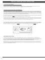
1
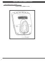
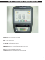
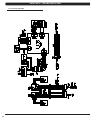
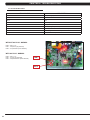
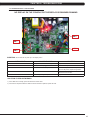
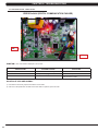
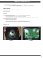
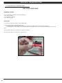
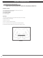
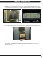
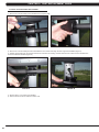
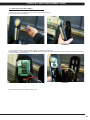
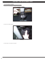
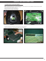
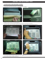
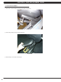
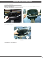
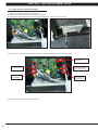
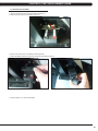
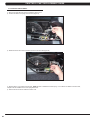
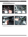
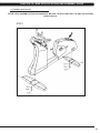
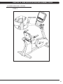
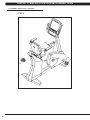
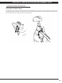
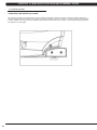
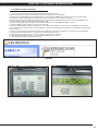
H5X-03 BIKE
SERVICE MANUAL
TABLE OF CONTENTS
CHAPTER 1: SERIAL NUMBER LOCATION . .................................................................. 1
CHAPTER 2: IMPORTANT SAFETY INSTRUCTIONS
2.1
2.2
Read and Save These Instructions . .......................................................................... 3
Electrical Requirements ............................................................................................. 4
CHAPTER 3: PREVENTATIVE MAINTENANCE
3.1
3.2
3.3
Recommended Cleaning Tips . .................................................................................. 5
Check for Damaged Parts ......................................................................................... 5
Care and Maintenance Instructions ........................................................................... 6
CHAPTER 4: CONSOLE OVERLAY AND WORKOUT DESCRIPTION
4.1
4.2
4.3
4.4
4.5
4.6
4.7
Console Description ...................................................................................................
Workout Setup Steps - Manual...................................................................................
Workout Setup Steps - Fat Burn.................................................................................
Workout Setup Steps - Level Based...........................................................................
Workout Setup Steps - Fitness Test............................................................................
Workout Setup Steps - Target Heart Rate..................................................................
Workout Setup Steps - Constant Watts......................................................................
7
8
8
8
9
10
10
CHAPTER 5: MANAGER MODE
5.1
5.2
Using Manager Mode ................................................................................................ 11
Manager Mode Overview............................................................................................ 11
CHAPTER 6: ENGINEERING MODE
6.1
Using Engineering Mode............................................................................................. 12
CHAPTER 7: SERVICE MODE
7.1
Using Service Mode.................................................................................................... 13
CHAPTER 8: TROUBLESHOOTING
8.1
8.2
8.3
8.4
8.5
8.6
8.7
8.8
8.9
8.10
8.11
8.12
8.13
8.14
Electrical Diagrams ....................................................................................................
Error Codes on the Console.......................................................................................
LCB LED Indicators....................................................................................................
Troubleshooting - Display Issues................................................................................
Troubleshooting - Error 0x04A0..................................................................................
Troubleshooting - Keypad Issues................................................................................
Troubleshooting - Resistance Issues..........................................................................
Troubleshooting - Pedals Slipping..............................................................................
Troubleshooting - Noise Issues...................................................................................
Troubleshooting - Heart Rate Issues..........................................................................
Entertainment Troubleshooting - Overview.................................................................
Entertainment Troubleshooting - Picture Fuzzy or Unclear........................................
Entertainment Troubleshooting - TV Will Not Turn On...............................................
Entertainment Troubleshooting - Controller Issues.....................................................
14
15
16
17
18
19
20
21
22
22
23
24
25
26
CHAPTER 9: PART REPLACEMENT GUIDE
9.1
9.2
9.3
9.4
Console Replacement.................................................................................................
Heart Rate Handlebar Replacement . ........................................................................
Heart Rate Grip Replacement ...................................................................................
Cup Holder Replacement............................................................................................
27
28
29
30
TABLE OF CONTENTS
9.5
9.6
9.7
9.8
9.9
9.10
9.11
9.12
9.13
9.14
9.15
9.16
9.17
9.18
9.19
9.20
9.21
9.22
Console Keypad / Overlay Replacement.................................................................... 31
Console Mast Replacement........................................................................................ 33
Seat Pad Replacement............................................................................................... 34
Back Pad Replacement.............................................................................................. 35
Stationary Handlebar Replacement............................................................................ 36
Pedals Replacement .................................................................................................. 37
Rear Shroud Replacement......................................................................................... 38
Front Shroud Replacement......................................................................................... 39
Battery Replacement................................................................................................... 40
Lower Control Board Replacement . .......................................................................... 41
Drive Belt Replacement ............................................................................................. 42
Generator Belt Replacement...................................................................................... 43
Generator Replacement.............................................................................................. 44
Pulley Axle Set Replacement.......................................................................................... 45
Crank Axle Set Replacement ......................................................................................... 46
Rear Stabilizer Replacement........................................................................................... 48
Front Stabilizer Replacement.......................................................................................... 49
Testing the Bike................................................................................................................ 50
CHAPTER 10: BIKE SPECIFICATION AND ASSEMBLY GUIDE
10.1
10.2
10.3
10.4
10.5 10.6
H5x-03 Bike Specifications.........................................................................................
Fasteners and Assembly Tools...................................................................................
Assembly Instructions ................................................................................................
Adjusting the Pedal Straps and Seat..........................................................................
Leveling the Bike.........................................................................................................
TV Bracket Installation................................................................................................
51
52
53
59
60
61
CHAPTER 11: SOFTWARE UPGRADE GUIDE
11.1
Software Upgrade Procedure..................................................................................... 65
iii
CHAPTER 1: SERIAL NUMBER LOCATION
1.1 SERIAL NUMBER LOCATION
A serial number plate is located behind the seat in the seat track. There is also a serial number tag on the middle of the main frame pointed
towards the floor.
1
CHAPTER 1: SERIAL NUMBER LOCATION
1.1 SERIAL NUMBER LOCATION - CONTINUED
CONSOLE SERIAL NUMBER LOCATION
2
CHAPTER 2: IMPORTANT SAFETY INSTRUCTIONS
2.1 READ AND SAVE THESE INSTRUCTIONS
To ensure your safety and protect the equipment, read all
instructions before operating the MATRIX H5x-03 Bike.
To ensure proper use of the Matrix H5x-03 Bike, make sure that all
users read this manual. Remind the users that before undertaking
any fitness program, they should obtain complete physical
examinations from their physicians. If, at any time while exercising,
the user experiences dizziness, pain, or shortness of breath,
nausea or feels faint, he or she must stop immediately.
CAUTION! If you experience chest pains, nausea, dizziness,
or shortness of breath, stop exercising immediately and consult your physician before continuing.
CAUTION! Any changes or modifications to this equipment
could void the product warranty.
* This bike is only to be used for its intended purpose described in this
manual. Do not use attachments that have not been recommended
by Matrix.
* Never drop or insert objects into any opening. Keep hands away
from moving parts. If the item cannot be reached, contact a Matrix
authorized dealer for assistance.
* Never operate the unit if it is damaged, not working properly, when
it has been dropped, or has been dropped in water.
* Keep hands and feet clear at all times from moving parts to avoid
injury.
* Do not use this product outdoors, near swimming pools or in areas
of high humidity.
* Do not operate where aerosol (spray) products are being used or
when oxygen is being administered.
* Do not use this product in bare feet. Do not wear shoes with heels,
leather soles, cleats, or spikes while exercising.
* Do not remove the side covers. Service should only be done by an
authorized service technician.
* Close supervision is necessary when used near children, invalids,
or disabled people.
* When the bike is in use, young children and pets should be kept at
least 3 meters / 10 feet away.
* Assemble and operate the bike on a solid, level surface.
* Never face backward while using the Matrix H5x-03 Bike.
* Use the stationary handlebars when mounting or dismounting the
bike.
* Do not wear clothing that might catch on any moving parts of this
bike.
3
CHAPTER 2: IMPORTANT SAFETY INSTRUCTIONS
2.2 ELECTRICAL REQUIREMENTS
The Matrix 5 Series Hybrid Bike is designed to be self powered. NOTE: If an add on TV (using a bracket) is added to the unit, it must be
plugged in, or the TV will not operate correctly. If the Bike will be plugged in, follow the requirements below.
MATRIX DEDICATED CIRCUIT/ELECTRICAL REQUIREMENT INFO
All Matrix Bikes require the use of a 15 amp or 20 amp “dedicated circuit,” with a non-looped (isolated) neutral/ground, for the power requirement.
Quite simply this means that each outlet you plug Bikes into should not have anything else running on that same circuit besides other Bikes (up to
3 per 15 amp circuit and 4 per 20 amp circuit). The easiest way to verify this is to locate the main circuit breaker box, and turn off the breaker(s)
one at a time. Once a breaker has been turned off, the only thing that should not have power to it are the Bikes in question. No lamps, vending
machines, fans, sound systems, or any other item should lose power when you perform this test.
Non-looped (isolated) neutral/grounding means that each circuit must have an individual neutral/ground connection coming from it, and terminating
at an approved earth ground. You cannot “jumper” a single neutral/ground from one circuit to the next.
In addition to the dedicated circuit requirement, the proper gauge wire must be used from the circuit breaker box, to each outlet that will have the
maximum number of units running off of it. If the distance from the circuit breaker box, to each outlet, is 100 ft or less, then 12 gauge wire may be
used. For any distance greater than 100 ft from the circuit breaker box to the outlet, 10 gauge wire must be used.
For your safety and Bike performance, the ground on this circuit must be non-looped. Please refer to NEC article 210-21 and 210-23. Your Bike is
provided with a power cord with a plug listed below and requires the listed outlet. Any alterations of this power cord could void all warranties for
this product. Multiple Bikes can be powered on one dedicated circuit. (3 units per 15 Amp and 4 units per 20 Amp dedicated circuit.)
GROUNDING INSTRUCTIONS:
The Matrix H5x-03 Hybrid Bike must be grounded. If it should malfunction or break down, grounding provides a path of least resistance for
electric current to reduce the risk of electric shock. The Bike is equipped with a cord having an equipment grounding conductor and a grounding
plug. The plug must be plugged into an appropriate outlet that is properly installed and grounded in accordance with all local codes and
ordinances. If the user does not follow these grounding instructions, the user could void the Matrix limited warranty.
DANGER: Improper connection of the equipment grounding conductor can result in the risk of electric shock. Check with a qualified electrician
if the user is in doubt as to whether the product is properly grounded. Do not modify the plug provided with the product if it will not fit the outlet,
have a proper outlet installed by an electrician.
4
CHAPTER 3: PREVENTATIVE MAINTENANCE
3.1 RECOMMENDED CLEANING TIPS
Preventative maintenance and daily cleaning will prolong the life and
look of your MATRIX H5x-03 Bike
Please read and follow these tips.
*Position the equipment away from direct sunlight. The intense UV
light can cause discoloration on plastics.
*Locate your equipment in an area with cool temperatures and low
humidity.
* Clean with a soft 100% cotton cloth.
*Clean with soap and water or other non-ammonia based all purpose cleaners.
*Wipe seats, pedals, console, heart rate grips, and the handlebar
clean after each use.
3.2 CHECK FOR DAMAGED PARTS
DO NOT use any equipment that is damaged or has worn or
broken parts. Use only replacement parts supplied by Matrix
Fitness Systems.
MAINTAIN LABELS AND NAMEPLATES. Do not remove labels
for any reason. They contain important information. If unreadable
or missing, contact Matrix Fitness Systems for a replacement at
866-693-4863 or www.matrixfitness.com.
MAINTAIN ALL EQUIPMENT. Preventative maintenance is the
key to smoothly operating equipment. Equipment needs to be
inspected at regular intervals. Defective components must be
kept out of use until they are repaired. Ensure that any person(s)
making adjustments or performing maintenance or repair of any
kind is qualified to do so. Matrix Fitness Systems will provide
service and maintenance training at our corporate facility upon
request or in the field if proper arrangements are made.
*Do not pour liquids directly onto your equipment. This can cause
damage to the equipment and in some cases electrocution.
* Check pedal straps weekly for wear.
* Adjust leveling feet when equipment wobbles or rocks.
* Maintain a clean area around the equipment, free from dust and
dirt.
5
CHAPTER 3: PREVENTATIVE MAINTENANCE
3.3 CARE AND MAINTENANCE INSTRUCTIONS
In order to maximize life span, and minimize down time, all MATRIX equipment requires regular cleaning, and maintenance items performed on
a scheduled basis. This section contains detailed instructions on how to perform these items and the frequency of which they should be done.
Some basic tools and supplies will be necessary to perform these tasks which include (but may not be limited to):
* Metric Allen wrenches
* #2 Phillips head screwdriver
* Adjustable wrench
* Torque wrench (capability to read foot lbs and inch lbs)
* Lint free cleaning cloths
* Teflon based spray lubricant such as "Super Lube" or other Matrix approved products.
* Mild water soluble detergent such as "Simple Green" or other Matrix approved products
* Vacuum cleaner with an extendable hose and crevasse tool attachment.
You may periodically see addendums to this document, as the Matrix Technical Support Team identifies items that require specific attention, the
latest version will always be available on the Matrix web site at www.matrixfitness.com.
DAILY MAINTENANCE ITEMS
1) Look and listen for loose fasteners, unusual noises, and any other indications that the equipment may be in need of service.
2) Clean the bike before and after each use, including:
a. Use a damp, soft cloth with water or mild liquid detergent to clean all exposed surfaces. DO NOT use ammonia, chlorine, or any acid
based cleaners. NOTE: Spray cleaner onto a cloth before using, never spray cleaner directly onto the equipment.
b. Keep the console display free of fingerprints and salt build up caused by sweat.
WEEKLY MAINTENANCE ITEMS
1) Frequently vacuum the floor beneath the unit to prevent the accumulation of dust and dirt which can affect the smooth operation of the unit.
2) Check the pedal straps for damage.
3) Clean the grooves on the foot pedals.
MONTHLY MAINTENANCE ITEMS
1) Inspect the console, seat, pedals, and shrouds for damage.
2) Tighten the pedals onto their respective cranks using a 15 mm wrench.
3) Adjust the leveling feet if equipment rocks or wobbles.
YEARLY MAINTENANCE ITEMS
1) Remove the front shrouds and check the belt for damage, alignment, and proper tension.
6
CHAPTER 4: CONSOLE OVERLAY AND WORKOUT DESCRIPTION
4.1 CONSOLE DESCRIPTION
WORKOUT KEYS: Simple program view and selection buttons.
GO: One touch Start.
ENTER: To confirm each program setting.
UP / DOWN LEVEL: Easy information and level selection.
UP / DOWN TIME: Easy information and time adjustment.
STOP: Ends workout and shows workout summary data.
NUMBER KEYPAD: Workout data input for workout setup. Level adjustment during workout.
COOL DOWN: Puts the Bike into Cool Down Mode.
FAN: Allows for fan speed selection (fan has 3 operating speeds).
TOGGLE DISPLAY: Allows user to select what information is displayed on the console.
7
CHAPTER 4: CONSOLE OVERLAY AND WORKOUT DESCRIPTION
4.2 WORKOUT SETUP STEPS - MANUAL
4.4 WORKOUT SETUP STEPS - LEVEL BASED
GO - Press to immediately begin a workout. Workout, resistance
ROLLING HILLS - The Rolling Hills program is a level based
1) Start pedaling and press the GO key to begin your workout. 2)
The display will read 3, 2, 1, Begin and then the program will start.
1) Start pedaling and press the ROLLING HILLS key.
2) Select Level by using the UP or DOWN LEVEL keys and press
ENTER.
3) Select Time by using the UP or DOWN LEVEL keys and press
ENTER.
4) Select Weight by using the UP or DOWN LEVEL keys and press
ENTER.
5) The display will read 3, 2, 1, Begin and then the program will
start.
level, and time will automatically go to default settings. Pressing
GO will not prompt user for age, weight, or level settings.
MANUAL - Manual allows the user to input more information
while defining their own workout. Calorie expenditure will be more
accurate when inputting information in Manual than by pressing GO.
1) Start pedaling, press the MANUAL key.
2) Select Level by using the UP or DOWN LEVEL keys and press
ENTER.
3) Select Time by using the UP or DOWN LEVEL keys and press
ENTER.
4) Select Weight by using the UP or DOWN LEVEL keys and press
ENTER.
5) The display will read 3, 2, 1, Begin and then the program will
start.
4.3 WORKOUT SETUP STEPS - FAT BURN
FAT BURN - Fat burn is a level based program that is designed
program that automatically adjusts the resistance level to simulate
real terrain.
INTERVAL TRAINING - The Interval Training program is a
level based program that automatically adjusts the resistance of the
machine from low to high intensity settings at regular intervals.
1) Start pedaling and press the INTERVAL TRAINING key.
2) Select Level by using the UP or DOWN LEVEL keys and press
ENTER.
3) Select Time by using the UP or DOWN LEVEL keys and press
ENTER.
4) Select Weight by using the UP or DOWN LEVEL keys and press
ENTER.
5) The display will read 3, 2, 1, Begin and then the program will
start.
to help users burn fat through various resistance level changes.
1) Start pedaling and press the FAT BURN key.
2) Select Level by using the UP or DOWN LEVEL keys and press
ENTER.
3) Select Time by using the UP or DOWN LEVEL keys and press
ENTER.
4) Select Weight by using the UP or DOWN LEVEL keys and press
ENTER.
5) The display will read 3, 2, 1, Begin and then the program will
start.
8
RANDOM - Random is a level based workout that randomly
adjusts the resistance of the machine.
1) Start pedaling and press the key next to RANDOM key.
2) Select Level by using the UP or DOWN LEVEL keys and press
ENTER.
3) Select Time by using the UP or DOWN LEVEL keys and press
ENTER.
4) Select Weight by using the UP or DOWN LEVEL keys and press
ENTER.
5) The display will read 3, 2, 1, Begin and then the program will
start.
CHAPTER 4: CONSOLE OVERLAY AND WORKOUT DESCRIPTION
4.5 WORKOUT SETUP STEPS - FITNESS TEST
FITNESS TEST -The Cooper Fitness Test measures cardiovascular fitness and proves an estimated sub-maximal VO2 result. It is based
on power output according to ACSM standards and was developed by the Cooper Institute© (www.cooperinstitute.org). User RPMs must
remain between 60-80 RPM during the test. The test will end when the user can no longer maintain this speed. Use of a heart rate strap is
optional but provides more data.
The test starts at a low intensity level and gradually increases in intensity (difficulty) every 2 minutes. As it increases, the user must maintain
60-80 RPM to advance to the next level. The test could take upwards of 30+ minutes for very fit individuals. Once the test ends a recovery
period (cool down) will begin and the user's results are calculated and displayed. Results are based on the number of stages completed.
Incline will not be adjustable during the test.
1)
2)
3)
4)
5)
6)
Start pedaling and press the FITNESS TEST key.
Select Age by using the UP or DOWN LEVEL keys and press ENTER.
Select Gender by using the UP or DOWN LEVEL keys and press ENTER.
Select Weight by using the UP or DOWN LEVEL keys and press ENTER.
The display will read 3, 2, 1, Begin and then the program will start.
Once the workout is complete, the display will read the results of the Fitness Test.
STAGES COMPLETED:
1
2
3
4
5
6
7
8
9+
Well Below Average
Well Below Average
Below Average
Below Average
Average
Average
Above Average
Above Average
Well Above Average
9
CHAPTER 4: CONSOLE OVERLAY AND WORKOUT DESCRIPTION
4.6 WORKOUT SETUP STEPS - TARGET HEART RATE
TARGET HEART RATE - The Matrix H5x-03 Bike comes with
standard digital contact heart rate sensors and are POLAR telemetry
compatible. The heart rate control workout mode allows the user to
program their desired heart rate zone, and the bike will automatically
adjust the level based upon the user's heart rate. The heart rate
zone is calculated using the following equation: (220-Age)8%=target
heart rate zone. The user must wear a POLAR telemetric strap or
continually hold onto the contact heart rate grips for this workout.
Locate the metal sensors on the handlebars of the bike. Notice
that there are two separate pieces of metal on each grip. You must
be making contact with both pieces of each grip to get an accurate
heart rate reading. You can grab these sensors in any program to
view your current heart rate.
1) Start pedaling and press the HEART RATE key.
2) Select Age by using the UP or DOWN LEVEL keys and press
SELECT.
3) Select Target HR Percentage by using the UP or DOWN LEVEL
keys and press SELECT.
4) Select Time by using the UP or DOWN LEVEL keys and press
SELECT.
5) Select Weight by using the UP or DOWN LEVEL keys and press
SELECT.
6) The display will read 3, 2, 1, Begin and the program will start.
10
4.7 WORKOUT SETUP STEPS - CONSTANT WATTS
CONSTANT WATTS - Constant Watts is a unique program
that allows you to vary your cadence or RPM and the bike's
resistance level will adjust accordingly to your selected goal. The
quicker you pedal, the less resistance for the goal selected.
1) Start pedaling and press the CONSTANT WATTS key.
2) Select Watts by using the UP or DOWN LEVEL keys and press
SELECT.
3) Select Time by using the UP or DOWN LEVEL keys and press
SELECT.
4) Select Weight by using the UP or DOWN LEVEL keys and
press SELECT.
5) The display will read 3, 2, 1, Begin and the program will start.
CHAPTER 5: MANAGER MODE
5.1 USING MANAGER MODE
The Manager's Custom Mode allows the club owner to customize the bike for the club.
1) To enter Manager Mode, press and hold down the UP and DOWN LEVEL keys. Continue to hold down these two keys until the display
reads Manager Mode and hit ENTER (Figure A).
2) To scroll through the list of options in Manager Mode, use the UP and DOWN LEVEL keys. Each of the custom settings will show on the
display.
3) To select a custom setting, press the ENTER key when the desired setting is shown.
4) To change the value of the setting, use the UP and DOWN LEVEL keys.
5) To confirm and save the value of the setting, press the ENTER key.
6) To exit the setting without saving, press the BACK key.
7) Press and hold the STOP key for 3-5 seconds to return to normal operation.
5.2 MANAGER MODE OVERVIEW
CUSTOM SETTING
DEFAULT
MINIMUM
MAXIMUM
DESCRIPTION
Maximum Time
60 min
10 min
95 min
Sets the total run time of any program.
Default Time
30 min
10 min
Maximum
Time
Setting
Workout time when GO is pressed or when no time is selected
during program set up.
Default Level
1
1
20
Starting resistance when GO is pressed or when no resistance is
selected during program set up.
Default Age
30
10
100
Starting age when GO is pressed or when no age is selected during
program set up.
Default User Weight
150 lbs /
75 kg
80 lbs / 36
kg
400 lbs /
181 kg
Weight used for program calorie expenditure calculations.
Accumulated Distance
N/A
0
99,999
Miles
Total distance for all programs.
Accumulated Time
N/A
0
999,999
hours
Total time for all programs displayed in hours.
Software Version
N/A
N/A
N/A
Current version of console software.
Timer Mode
Up
Up
Down
Determines whether the timer counts up or down.
Speed / Distance Mode
Mile
Mile
Kilometer
Displays distance in miles or kilometers.
Out of Order
No
No
Yes
Locks the machine when out of order.
Gender
Male
Male
Female
Determines the gender of the user when not selected during program
set up.
Language
English
English
English
Sets the language for the console. Select between English, Spanish,
German, French, Italian, and Dutch.
Sound Mode
On
On
Off
Turns the chime on / off when a button is pressed.
11
CHAPTER 6: ENGINEERING MODE
6.1 USING ENGINEERING MODE
To enter Engineering Mode, hold the LEVEL UP and DOWN keys for 3-5 seconds until Manager Mode appears on the middle LED display.
Press the LEVEL UP or DOWN key to scroll to Engineering Mode. Press ENTER to go into Engineering Mode.
12
CODE
DEFAULT
OPTIONS
DESCRIPTION
Disable Errors
No
Yes or No
No - Shows A-C class error
codes. Yes - Shows only C class
error codes.
Speed Units
Mile
Mile or Kilometer
Set for Mile or Kilometer.
Machine Type
H5x-03
H5x, R5x, U5x, E5x-02 or E5x-03
Set the Hybrid bike as H5x.
Power Save Time
30 Seconds
30-60 Seconds
Power saving time for the self
powered frame.
Pause Time
30 Seconds
15 - 120 Seconds
For non self powered frames
only. Not used on this model.
Serial Number
N/A
N/A
Serial Number input is available
for both the Console and Frame.
Use the number keys and UP
/ DOWN LEVEL keys to enter
Engineering Mode. Due to the
limited LED characters, 2 layers
are used to enter the serial
number. First Layer:
- PPPPP V
- PPPPP is the product name.
- V is the version. If the
version is A, just leave this blank.
Second Layer
- YY MM nnnnn.
- YY is the year (11, 12).
- MM is the month (e.g. 08,
09, 10).
- nnnnn is the actual serial
number.
Use the UP / DOWN LEVEL keys
to navigate the layers and the
number keys to input the serial
number. The product name is
dependent on the Machine Type
setting.
For example, the console
is EP90 with ver. B and the
manufactured date is 2011.08
with 98765. The frame is CB72
with ver. B and the manufactured
date is 2011.06 with 12345. Their
serial numbers are:
Console SN: EP90B 1rst layer,
110898765 2nd layer.
Frame SN: CB72B 1rst layer,
110612345 2nd layer.
Club ID
N/A
N/A
This sets the club ID for clubs
using Asset Management.
Sleep Time
Off
Off or On (1-30 Minutes)
If there is no use of the machine
over a period of time, the console
LEDs will turn off (go into sleep
mode).
Audio Source
Off
Off / TV / PC TV / Remote TV
Manual setting that sets which
outside TV will have audio
through the console audio ports.
CHAPTER 7: SERVICE MODE
7.1 USING SERVICE MODE
To enter Service Mode, hold the LEVEL UP and DOWN keys for 3-5 seconds until Manager Mode appears on the middle LED display. Press
the LEVEL UP or DOWN key to scroll to Service Mode. Press ENTER to go into Service Mode.
CODE
DEFAULT
OPTIONS
Service 1
Display Test
Press the ENTER key repeatedly
to check each set of LEDs on the
display sequentially.
Service 2
Keypad Test
Press any key and the display
should show the corresponding
message.
Service 3
Distance / Time
Service 4
CSafe / RF Test
Press the ENTER key to test
CSAFE. Press the ENTER key
again to test the RF.
Service 5
Error Log
Shows the last 10 errors. Press
and LEVEL UP and DOWN for 3
seconds to clear the errors.
Service 6
Set Date / Time
Press the LEVEL keys to move
cursor, the number keys to set
date / time, and the ENTER key
to save.
Service 7
Export and Import Parameter
Export Parameter - Export all
parameters to a USB device.
Import Parameter 1 - Imports the
engineer parameters to a USB
device except serial number,
accumulated distance and time.
Import Parameter 2 - Imports the
engineer parameters to a USB
device.
Service 8
WiFi Function
Automatically detects the
available IP address and displays
it.
Distance:
Mile 0 - 99999
Kilometer 0 - 160898
Time:
0 - 999999
DESCRIPTION
Manually sets the Accumulated
Distance and Time.
13
CHAPTER 8: TROUBLESHOOTING
8.1 ELECTRICAL DIAGRAM
14
CHAPTER 8: TROUBLESHOOTING
8.2 ERROR CODES ON THE CONSOLE
CODE
CLASS
DESCRIPTION
SOLUTION
0x02AB
C
Machine type error.
Set the correct machine type in
Engineering Mode.
0x02B4
C
Resistance type error.
Set the correct machine type in
Engineering Mode.
0x0201
A
Low voltage on the battery
(voltage under 11.2V).
Charge by running or by plugging
in the AC adapter.
0x0247
B
LCB failed (memory write error /
feedback ADC error).
Replace the LCB.
0x0248
B
Battery failure or disconnection
(Voltage under 8V or over 15V).
Check the wire connections at
the battery. Replace the battery.
0x0441
B
When the UCB implements
a command, the LCB is not
receiving this command.
Check the machine type in
Engineering Mode. Check the
connections at the UCB and LCB.
0x04A0
C
Digital Communication Failure.
LCB has no return message for
the UCB for 3 seconds.
Check the console cable
connections at the UCB and
LCB. Replace the UCB or LCB
as needed.
0x04B0
C
UCB No Response.
Check the console cable
connections at the UCB and
LCB. Replace the UCB or LCB
as needed.
CLASS C ERRORS WILL DISPLAY ON THE CONSOLE.
CLASS A OR B ERRORS WILL ONLY DISPLAY IN SERVICE MODE 5.
15
CHAPTER 8: TROUBLESHOOTING
8.3 LCB LED INSTRUCTIONS
LED INDICATOR
DESCRIPTION
LED 1
RPM (AC Plug In).
LED 2
+5V
LED 3
+15V
LED 4
Bus Voltage
LED 5
RPM (Generator).
LED 6
Status 1 (Program operation).
LED 7
Status 2 (Resistance value in middle 1/2 VCC).
LED 8
Status 3 (Digital Communication).
LED 9
+12V (Console Power).
WITHOUT AC PLUG - NORMAL
LED 2 - LED 9 - On.
LED 1 - Off (No AC plug detected).
LED 5 - On (Generator power detected),
WITH AC PLUG - NORMAL
LED 2 - LED 9 - On.
LED 1 - On (AC plug detected).
LED 5 - Off (No Generator power detected).
LED 1
LED 5
16
CHAPTER 8: TROUBLESHOOTING
8.4 TROUBLESHOOTING - DISPLAY ISSUES
NO DISPLAY ON THE CONSOLE OR THE DISPLAY IS DIM WHEN RUNNING
LED 9
LED 1
LED 8
LED 5
SYMPTOM: The console will not power up or the display is dim.
CHECK POINT
POSSIBLE ISSUE
SOLUTION
LEDs 2, 3, 4, 6, and 7 should be ON.
If they are OFF, the LCB is damaged.
Replace the LCB.
if LED1 is OFF.
No AC power cord plugged in.
Normal for an unpowered unit.
if LED 5 is OFF.
Generator has no RPM output.
Normal for a powered unit. If unpowered and
issue is still present, replace the generator.
if LED 8 is OFF.
Bad communication between UCB and LCB.
Reconnect the console cable at the LCB and
UCB and check for kinks.
if LED 9 is OFF.
LCB is not providing 12V power to the UCB.
Replace the LCB.
SOLUTION IF LEDS ARE NORMAL:
1) If the LEDs are lit normally, replace the UCB and console cable.
2) if the issue is still present after the UCB and console cable are replaced, replace the LCB.
17
CHAPTER 8: TROUBLESHOOTING
8.5 TROUBLESHOOTING - ERROR 0x04A0
ERROR 0x04A0 (DIGITAL COMMUNICATION FAILURE)
LED 1
LED 8
SYMPTOM: Error code 0x04A0 is displayed on the console.
CHECK POINT
POSSIBLE ISSUE
LEDs 2, 3, 4, 6, 7 should be ON.
If they are OFF, the LCB is damaged.
Replace the LCB.
if LED1 is OFF.
No AC power cord plugged in.
Normal for an unpowered unit.
if LED 8 is OFF.
Bad communication between UCB and LCB.
Reconnect the console cable at the LCB and
UCB and check for kinks.
SOLUTION IF LEDS ARE NORMAL:
1) If the LEDs are lit normally, replace the UCB and console cable.
2) if the issue is still present after the UCB and console cable are replaced, replace the LCB.
18
SOLUTION
CHAPTER 8: TROUBLESHOOTING
8.6 TROUBLESHOOTING - KEYPAD ISSUES
ALL OR SOME OF THE FUNCTION KEYS DO NOT RESPOND
POSSIBLE CAUSES:
1) The keypad connection ribbon cable has not been plugged in correctly.
2) The keypad is damaged.
3) The UCB is damaged.
SOLUTION:
1) Perform a keypad test in Service Mode:
a. Press and hold both the UP and DOWN LEVEL keys until Manager Mode appears on the display.
b. Use the UP and DOWN LEVEL keys to scroll to Service Mode 5 and press ENTER.
c. Test the affected keypad. If the keypad works in the keypad test it may not be a functioning key in the program used for testing it.
2) Check the connections of the keypad at the UCB.
a. Remove the console from the console mast.
b. Remove the 6 screws holding the back of the console to the front (Figure A).
c. Inspect the keypad ribbon cable connection at the UCB (Figure B).
d. Even if the keypad ribbon cable appears to be connected correctly, unplug and re-seat the cable.
3) Replace the affected keypad.
4) Replace the UCB.
FIGURE A
FIGURE B
19
CHAPTER 8: TROUBLESHOOTING
8.7 TROUBLESHOOTING - RESISTANCE ISSUES
HIGH OR NO RESISTANCE
POSSIBLE CAUSES:
1)
2)
3)
4)
The
The
The
The
console cable is damaged or not properly plugged in.
UCB is damaged.
Generator is damaged.
LCB is damaged.
SOLUTION:
1) Check the console cable connections at the UCB and LCB.
2) Check if the generator is outputting variable power:
a. Insert the probes from a multi-meter into the black and red wires on the generator wire harness connector (Figure A).
b. When pedaling, the output voltage from the generator should vary depending on the RPM. The generator should output 120 VAC at 94
RPM.
3) If the generator does not have variable power, replace the generator.
4) If the generator does have variable power, replace the LCB.
FIGURE A
20
CHAPTER 8: TROUBLESHOOTING
8.8 TROUBLESHOOTING - PEDALS SLIPPING
PEDALS SLIPPING
POSSIBLE CAUSES:
1) The belt tension is not enough.
2) The one way bearing is damaged.
SOLUTION:
1) Remove the covers and check the belt tension.
a. Tighten the drive belt tension if needed by moving the spring tension clip to another hole.
b. The generator belt should be tightened to 85 ft / lbs.
2) If the belts are tensioned correctly, the one way bearing is damaged, replace the drive assembly.
8.9 TROUBLESHOOTING - NOISE ISSUES
KNOCKING OR CREAKING NOISE
POSSIBLE CAUSES:
1) The pedal is on the crank too loosely.
2) The crank or axle is worn out.
3) The belt tension is not enough, or the belts are too dirty.
SOLUTION:
1) Retighten the pedal on the crank.
2) Replace the crank or axle as needed.
3) Remove the covers and check the belt tension.
a. Tighten the drive belt tension if needed by moving the spring tension clip to another hole.
b. The generator belt should be tightened to 85 ft / lbs.
4) Clean the belts. If they are worn or will not clean, replace the belts.
21
CHAPTER 8: TROUBLESHOOTING
8.10 TROUBLESHOOTING - HEART RATE ISSUES
HEART RATE FUNCTION DOES NOT WORK OR IS READING INCORRECTLY
POSSIBLE CAUSES:
1)
2)
3)
4)
5)
6)
The
The
The
The
The
The
chest strap being used is not making good contact with the user's chest.
chest strap is at a low battery status.
chest strap is damaged.
HR grips are damaged.
HR board is damaged.
UCB is damaged.
SOLUTION:
1) Re-center the chest strap below the user's pectoral muscle (Figure A) and check again.
2) Replace the battery in the chest strap.
3) Replace the chest strap.
4) If there is no HR present, replace the HR grips.
5) If there is a HR present but it is much higher than normal, replace the HR board.
6) If replacing the HR grips and board does not resolve the issues, replace the console.
FIGURE A
22
CHAPTER 8: TROUBLESHOOTING
8.11 ENTERTAINMENT TROUBLESHOOTING - OVERVIEW
1) S
ections 8.11 - 8.14 will help with diagnosing problems with TV and entertainment related equipment that is produced by Matrix Fitness Systems.
2) The H5x Bike has the capability of adding an external 15" TV with a bracket. A Matrix brand external TV will look similar to the TV in Figure A.
Your control keypad should look similar to Figure B. If your equipment looks different contact Matrix or the manufacturer of your TV equipment if
known.
FIGURE A
FIGURE B
3) Verify how your TV is mounted, compare your machine to Figure C which shows an external 15" TV directly mounted to a unit with a 5x console.
FIGURE C
4) F
or Matrix produced and mounted equipment you can use the information outlined in this section to help with any connection and power
issues you may have. If you have questions that are specific to the TV alone (settings, programming, menu options, etc) please see the
entertainment owner’s manual.
23
CHAPTER 8: TROUBLESHOOTING
8.12 ENTERTAINMENT TROUBLESHOOTING – PICTURE FUZZY OR UNCLEAR
1) Remove the TV back cover (Figure A) Using a verified good piece of coax cable, hook the coax directly to the TV jack. This bypasses
internal connections for your machine or TV stand (Figure B).
FIGURE A
FIGURE B
2) If this does not clear your picture the issue is with the club's signal. Make sure that the coax has a signal strength of at least 10db.
3) If Step 1 does clear your picture, check the internal cables and fittings inside your machine. Make sure you have no damage (kinks, cuts etc)
and no stray wires or poor fittings on the ends of the cables anywhere that the coax cable is connected (Figures C, D, & E). Fittings should have
a clean flush connector and no stray aluminum strands touching the center conductor. Replace or repair any suspect cables.
FIGURE C
FIGURE D
FIGURE E
4) If nothing is visibly wrong with any of the cables, fittings, or connectors replace the internal coax cables and connectors with known good
parts.
24
CHAPTER 8: TROUBLESHOOTING
8.13 ENTERTAINMENT TROUBLESHOOTING -TV WILL NOT TURN ON
1) If you have no picture at all check to see if you have any status lights on your entertainment keypad or TV. Status lights should be red when
off or in standby mode, and green when the TV is powered on. If you have lights of any color skip to Section 8.14.
2) Remove the TV back cover (Figure A) and check the connection of the TV power wire at the TV (Figure B). Also check the TV power wire
connection at the console (Figure C).
FIGURE A
FIGURE B
FIGURE C
3) After you have verified all connections are secure and a problem still exists verify power at the outlet (Figure D). If the outlet is not outputting
120 Volts, check fitness room power.
4) If internal TV power wire connections are good, verify 12 Volts power at the TV power wire where it plugs into the TV (wire in Figure B, shown
with multi - meter in Figure E). If 12 Volts are present, the issue is likely with the TV itself, contact Matrix Customer Service.
FIGURE D
FIGURE E
25
CHAPTER 8: TROUBLESHOOTING
8.14 ENTERTAINMENT TROUBLESHOOTING - CONTROLLER ISSUES
1) If you have status lights on the TV, but the On / Off button gives no response, disconnect and then re-connect the power to the bike from the
wall. Attempt to turn on the TV again using the On / Off button.
2) If the TV does not power on check the connection of the TV controller wire at the console (Figure A).
3) Also check the connection of the TV controller wire at the TV (Figure B).
FIGURE A
FIGURE B
4) If the TV does not power on with the TV keypad, attempt to power on the TV using the small handheld remote that came with the TV (Figure
C) (Used for changing menu and other settings). If the TV will function with the handheld remote, replace the TV controller wire. If the TV will not
function with handheld remote it is likely an issue with the TV itself, contact Matrix Customer Technical Support.
FIGURE C
26
CHAPTER 9: PART REPLACEMENT GUIDE
9.1 CONSOLE REPLACEMENT
1) Remove the 5 screws holding the console to the frame (Figure A).
FIGURE A
2) Disconnect the console cable and HR connections from the defective console and remove the console (Figure B).
FIGURE B
3) Reinstall the wire connections to the new console.
4) Carefully push the wires into the console and mast until they are clear of the console / mast connection and attach the console to the mast
using the 4 screws.
5) Test the bike for function as outlined in Section 9.22.
27
CHAPTER 9: PART REPLACEMENT GUIDE
9.2 HEART RATE HANDLEBAR REPLACEMENT
1) Remove the 2 screws holding on the handlebar cover (Figures A & B).
FIGURE A
FIGURE B
2) Remove the 4 screws holding the heart rate handlebar to the console mast being careful to support the handlebar (Figure C).
3) Carefully pull the wires from the console mast until the connectors are showing, and then disconnect the 3 wires from the handlebar and
remove the defective handlebar (Figure D).
FIGURE C
4) Reverse Steps 1-3 to install a new handlebar.
5) Test the bike for function as outlined in Section 9.22.
28
FIGURE D
CHAPTER 9: PART REPLACEMENT GUIDE
9.3 HEART RATE GRIPS REPLACEMENT
1) Remove the 3 screws holding the 2 halves of the HR grip together (Figure A).
2) Split the HR grip in half (Figure B).
FIGURE A
FIGURE B
3) Disconnect the level key and HR plate wiring (Figure C) and remove the HR grip.
4) Reverse Steps 1-3 to install a new HR grip. NOTE: When plugging in the HR plate wiring, the red wire should go to the top plate, the white
wire to the bottom HR plate (Figure D).
FIGURE C
FIGURE D
5) Test the Bike for function as outlined in Section 9.22.
29
CHAPTER 9: PART REPLACEMENT GUIDE
9.4 CUP HOLDER REPLACEMENT
1) Remove the 2 screws holding the cup holder to the console mast (Figure A).
FIGURE A
2) Remove the cup holder (Figure B).
FIGURE B
3) Reverse Steps 1-2 to install a new cup holder.
30
CHAPTER 9: PART REPLACEMENT GUIDE
9.5 CONSOLE KEYPAD / OVERLAY REPLACEMENT
NOTE: The instructions below are for console overlays / keypads, but the procedure is the same regardless of where the overlay / keypad is.
1) Turn off power and disconnect the cord from the machine.
2) Remove the console as outlined in Section 9.1.
3) Remove the back cover of the console (Figure A).
4) Unplug and remove the faulty overlay (Figure B).
FIGURE A
FIGURE B
5) Clean the console area with alcohol to remove any left over adhesive (Figure C).
6) Remove the protective film over the display window of the overlay (Figure D).
FIGURE C
FIGURE D
31
CHAPTER 9: PART REPLACEMENT GUIDE
9.5 CONSOLE KEYPAD / OVERLAY REPLACEMENT - CONTINUED
7) Peel part of the protective film from the back of the overlay (Figure E).
8) Push the overlay ribbon cable through the hole in the console and plug it in (Figure F).
FIGURE E
FIGURE F
9) Match the overlay to the cutout on the console (Figure G).
10) Press down on the corners of the overlay to keep it in place, then remove the protective film (Figure H & I).
11) Once the overlay is in the correct position, press down on the overlay with a cloth to adhere it to the console plastic (Figure J).
FIGURE G
FIGURE I
FIGURE H
FIGURE J
12) Use the same procedure to replace any additional faulty overlays. NOTE: Overlays can not be reused.
13) Test the bike for function as outlined in Section 9.22.
32
CHAPTER 9: PART REPLACEMENT GUIDE
9.6 CONSOLE MAST REPLACEMENT
1) Remove the console as outlined in Section 9.1.
2) Remove the HR handlebars as outlined in Section 9.2.
3) Lift up the rubber boot at the bottom of the console mast (Figure A).
FIGURE A
4) With the boot lifted, remove the 4 screws holding the console mast to the frame (Figure B).
FIGURE B
5) Pull the wires out the bottom of the console mast and remove the mast.
6) Reverse Steps 1-5 to install a new console mast. NOTE: When installing a new console mast, be sure to pull the console wires up through
the new mast prior to installing the 4 screws into the frame.
7) Test the bike for function as outlined in Section 9.22.
33
CHAPTER 9: PART REPLACEMENT GUIDE
9.7 SEAT PAD REPLACEMENT
1) Remove the 4 screws holding the seat pad to the seat post (Figure A).
FIGURE A
2) Lift the seat pad away from the seat post (Figure B).
FIGURE B
3) Reverse Steps 1-2 to install a new seat pad.
34
CHAPTER 9: PART REPLACEMENT GUIDE
9.8 BACK PAD REPLACEMENT
1) Using the tips of your fingers, remove the back cover of the back pad. The back cover is held on by plastic snap clips, and if pressure is
applied, the cover will pop off (Figure A).
2) Remove the 4 bolts holding the seat pad to the seat frame (Figure B).
FIGURE A
FIGURE B
3) Remove the back pad (Figure C).
FIGURE C
4) Reverse Steps 1-3 to install a new back pad.
35
CHAPTER 9: PART REPLACEMENT GUIDE
9.9 STATIONARY HANDLEBAR REPLACEMENT
1) Using the tips of your fingers, remove the back cover of the back pad. The back cover is held on by plastic snap clips, and if pressure is
applied, the cover will pop off (Figure A).
2) Remove the 4 bolts holding the stationary handlebar assembly to the seat frame (Figure B).
FIGURE A
FIGURE B
3) Remove the stationary handlebar (Figure C).
FIGURE C
4) Reverse Steps 1-3 to install a new stationary handlebar.
36
CHAPTER 9: PART REPLACEMENT GUIDE
9.10 PEDAL REPLACEMENT
1) Use a 15 mm wrench to remove the pedal from the crank (Figure A). NOTE: For the right side pedal, the threads are normal. For the left
side pedal, the threads are reversed (the pedal turns off counterclockwise).
FIGURE A
2) Remove the pedal (Figure B).
FIGURE B
3) Reverse Steps 1-2 to install a new pedal.
37
CHAPTER 9: PART REPLACEMENT GUIDE
9.11 REAR SHROUD REPLACEMENT
1) Remove the 9 screws attaching the right side rear shroud to the frame and to the left shroud (Figure A).
2) Remove the 3 screws attaching the left side rear shroud to the frame (Figure B).
FIGURE A
FIGURE B
3) Figure C shows both the rear shrouds removed.
FIGURE C
4) Reverse Steps 1-2 to install new rear shrouds.
38
CHAPTER 9: PART REPLACEMENT GUIDE
9.12 FRONT SHROUD REPLACEMENT
1) Remove the pedals as outlined in Section 9.10.
2) Remove the 8 screws attaching the right side front shroud to the frame and to the left shroud (Figure A).
3) Remove the 5 screws attaching the left side front shroud to the frame and entertainment port (Figure B).
FIGURE A
FIGURE B
4) Figure C shows both the front shrouds removed.
FIGURE C
5) Reverse Steps 1-3 to install a new front shroud.
39
CHAPTER 9: PART REPLACEMENT GUIDE
9.13 LOWER CONTROL BOARD REPLACEMENT
1) Remove the rear shrouds as outlined in Section 9.11.
2) Disconnect the 5 wire connections to the lower board (Figure A).
3) Remove the 2 screws holding the lower board to the frame (Figure B), and remove the lower board.
FIGURE A
FIGURE B
4) Reverse Steps 1-3 to install a new lower board. Figure C shows the electrical connections to the lower board.
3 Pin Connector from
the Generator
7 Pin Connector
from the Console
2 Pin Connector from
the AC power source
2 Pin Connector
from the Battery
2 Pin Connector
from the Resistor
FIGURE C
5) Test the bike for function as outlined in Section 9.22.
40
CHAPTER 9: PART REPLACEMENT GUIDE
9.14 BATTERY REPLACEMENT
1) Remove the left side rear shroud as outlined in Section 9.11.
2) Disconnect the 2 wires from the battery (Figure A).
FIGURE A
3) Remove the 2 wing nuts on the battery bracket (Figure B).
4) Swivel the battery bracket out of the way and remove the battery (Figure C).
FIGURE B
FIGURE C
5) Reverse Steps 1-4 to install a new battery.
41
CHAPTER 9: PART REPLACEMENT GUIDE
9.15 DRIVE BELT REPLACEMENT
1) Remove the right side front shroud as outlined in Section 9.12.
2) Unattach the tension set spring from the frame (Figure A).
FIGURE A
3) Rotate the tension set counter clockwise and remove the drive belt (Figure B).
FIGURE B
4) Reverse Steps 1-3 to install a new drive belt. NOTE: Be sure to reattach the tension spring. If more tension is needed on the drive belt,
multiple holes are available for the lower spring attachment.
5) Test the bike for function as outlined in Section 9.22.
42
CHAPTER 9: PART REPLACEMENT GUIDE
9.16 GENERATOR BELT REPLACEMENT
1) Remove the front shrouds as outlined in Section 9.12.
2) Loosen the nuts holding the generator to the frame (Figure A), and remove the nuts putting tension on the generator belt (Figure B).
FIGURE A
FIGURE B
3) Once the tension has been removed, the generator belt can be walked off of the pulley (Figure C).
4) Pull the generator out of the frame towards the front of the unit, and remove the generator belt (Figure D).
FIGURE C
FIGURE D
5) Reverse Steps 1-4 to install a new generator belt. NOTE: Be sure to re-tension the new generator belt to 85 ft / lbs.
6) Test the bike for function as outlined in Section 9.22.
43
CHAPTER 9: PART REPLACEMENT GUIDE
9.17 GENERATOR REPLACEMENT
1) Remove the front shrouds as outlined in Section 9.12.
2) Remove the nuts holding the generator to the frame (Figure A), and remove the nuts putting tension on the generator belt (Figure B).
FIGURE A
FIGURE B
3) Once the tension has been removed, the generator belt can be walked off of the pulley (Figure C).
4) Pull the generator out of the frame towards the front of the unit, and remove the generator belt (Figure D).
FIGURE C
5) Reverse Steps 1-4 to install a new generator.
6) Test the bike for function as outlined in Section 9.22.
44
FIGURE D
CHAPTER 9: PART REPLACEMENT GUIDE
9.18 PULLEY AXLE SET REPLACEMENT
1) Remove the front shrouds as outlined in Section 9.12.
2) Remove the drive belt as outlined in Section 9.15.
3) Loosen the nuts holding the generator to the frame (Figure A), and remove the nuts putting tension on the generator belt (Figure B).
FIGURE A
FIGURE B
4) Once the tension has been removed, walk the generator belt off of the pulley (Figure C).
FIGURE C
45
CHAPTER 9: PART REPLACEMENT GUIDE
9.18 PULLEY AXLE SET REPLACEMENT - CONTINUED
5) Remove the C-clip holding the bearing in place on the right side of the frame (Figure D).
6) Remove the bearing (Figure E).
FIGURE D
FIGURE E
7) Remove the large nut holding in the pulley axle assembly with a large channel lock pliers or a pipe wrench (Figure F).
8) Once the large nut is removed, the pulley axle set can be hammered out of the frame (Figure G), it should be removed from the user's left
side.
FIGURE F
9) Reverse Steps 1-8 to install a new pulley axle set.
10) Test the bike for function as outlined in Section 9.22.
46
FIGURE G
CHAPTER 9: PART REPLACEMENT GUIDE
9.19 CRANK AXLE SET REPLACEMENT
1)
2)
3)
4)
Remove the front shrouds as outlined in Section 9.12.
Remove the drive belt as outlined in Section 9.15.
Remove the 3 screws holding the crank axle bearings in place on both sides (Figure A).
Bend the tabs of the nut on the left side of the frame so that this nut will turn (Figure B).
FIGURE A
FIGURE B
5) Use a 32 mm wrench to remove the crank axle nuts (Figure C). NOTE: This nut is reverse threaded.
FIGURE C
6) Once the nuts are removed, the crank axle can be removed from the frame from the right side.
7) Reverse Steps 1-6 to install a new crank axle set.
8) Test the bike as outlined in Section 9.22.
47
CHAPTER 9: PART REPLACEMENT GUIDE
9.20 REAR STABILIZER REPLACEMENT
1) Lean the bike to one side and remove the 4 screws holding the rear stabilizer to the frame (Figure A).
FIGURE A
2) Remove the rear stabilizer (Figure B).
FIGURE B
3) Reverse Steps 1-2 to install a rear stabilizer.
48
CHAPTER 9: PART REPLACEMENT GUIDE
9.21 FRONT STABILIZER REPLACEMENT
1) Lean the bike to one side and remove the 4 screws holding the front stabilizer to the frame (Figure A).
FIGURE A
2) Remove the front stabilizer (Figure B).
FIGURE B
3) Reverse Steps 1-2 to install a new front stabilizer.
49
CHAPTER 9: PART REPLACEMENT GUIDE
9.22 TESTING THE BIKE
ONCE THE UNIT OR REPLACEMENT PART IS FULLY INSTALLED AND ASSEMBLED AND
PROPERLY PLACED ON THE FLOOR, USE THE FOLLOWING INSTRUCTIONS TO SETUP
AND TEST THE MACHINE:
1) Check that the console is set for hybrid bike.
a. Press and hold both LEVEL keys until Manager Mode appears on the display.
b. Press the UP or DOWN LEVEL keys until Engineering Mode appears on the display.
c. Use the UP or DOWN LEVEL keys to scroll to Machine Type.
d. Press ENTER on Machine Type and make sure it is set for H5x.
e. If Machine Type is not set for H5x, change to H5x using the UP or DOWN LEVEL key and press ENTER to save.
f. Press and hold the STOP key for 3-5 seconds to return to normal function.
2) Without hitting start or entering any program modes, sit on the bike and hold the handlebars while pedaling to simulate exercising. While
moving, listen for any odd noises or squeaks.
3) After stopping movement, press the green GO key and begin pedaling.
4) Grasp the hand grips to check for proper heart rate response.
5) Press the level up and down buttons on the console and hand grips to make sure resistance is fully functional.
6) If everything functions properly, stop pedaling and the unit will reset to normal operation within 30 seconds.
50
CHAPTER 10: BIKE SPECIFICATIONS AND ASSEMBLY GUIDE
10.1 H5x-03 BIKE SPECIFICATIONS
CONSOLE
Display Type
Dot-Matrix LED
Display Feedback
Time, Distance, Calories, Speed, Heart Rate, METs, Watts, Level,
RPM
Programs
Manual, Rolling, Intervals, Fat Burn, Random, Fitness Test, Target
HR, Constant Watts
Resistance Levels
25
CSafe, FitLinxx Ready
Yes
Fitconnexion Ready
Yes
Wireless Data Transmitter
Yes
iPod Compatible
Yes - Charging Only
Nike + iPod Compatible
No
Personal Fan
Yes
Virtual Active Ready
No
Asset Management Ready
Yes
TECHNICAL DATA
Resistance Technology
JID Brushless Generator
Power Requirements
Self Powered or Optional 120V / 60Hz AC
Minimum Watts
12
Overall Dimensions (L x W x H)
58" x 29" x 59" / 147.3 x 73.7 x 149.9 cm
Maximum User Weight
400 lbs / 181.4 kg
Unit Weight
167 lbs / 75.7 kg
Shipping Weight
204 lbs / 92.6 kg
Transport Wheel
Yes
USER DATA
Contact Heart Rate Sensors
Yes
Telemetric Heart Rate Receiver
Yes
Handle Bar Design
Front vertical ergo bend
Thumb Switch Controls
Yes
51
CHAPTER 10: BIKE SPECIFICATIONS AND ASSEMBLY GUIDE
10.2 FASTENERS AND ASSEMBLY TOOLS
52
QUANTITY
PART #
1
Z05
1
Z04
1
Z01
1
Z03
1
SKETCH
DESCRIPTION
NOTES
4 MM ALLEN WRENCH
PURPLE
See sketch of Z05
5MM ALLEN WRENCH
PURPLE
See sketch of Z05
6 MM ALLEN WRENCH
PURPLE
OPEN END WRENCH (15 & 17MM)
PURPLE
Z02
#2 PHILLIPS SCREWDRIVER
PURPLE
4
Z11
HEX HEAD SCREW (M8 X 25L)
WHITE
4
Z12
SPRING WASHER
WHITE
2
Z13
BUTTON HEAD SCREW (M5 X 10L)
WHITE
8
Z21
HEX HEAD SCREW (M8 X 20L)
BLACK
8
Z22
FLAT WASHER
BLACK
8
Z23
SPRING WASHER
BLACK
4
Z31
BUTTON HEAD SCREW (M8 X 15L)
YELLOW
4
Z32
FLAT WASHER
YELLOW
4
Z33
SPRING WASHER
YELLOW
2
Z34
HEX HEAD SCREW (M8 X 25L)
YELLOW
4
Z41
HEX HEAD SCREW (M8 X 50L)
RED
4
Z42
ARC WASHER
RED
4
Z43
SPRING WASHER
RED
4
Z51
HEX HEAD SCREW (M5 X 15L)
GREEN
4
Z52
FLAT WASHER
GREEN
4
Z53
SPRING WASHER
GREEN
1
Z71
ADJUSTMENT FOOT
CHAPTER 10: BIKE SPECIFICATIONS AND ASSEMBLY GUIDE
10.3 ASSEMBLY INSTRUCTIONS
AFTER THESE ASSEMBLY STEPS ARE COMPLETE, BE SURE TO SETUP AND TEST THE UNIT AS OUTLINED
IN SECTION 9.22.
STEP 1
53
CHAPTER 10: BIKE SPECIFICATIONS AND ASSEMBLY GUIDE
10.3 ASSEMBLY INSTRUCTIONS - CONTINUED
STEP 2
54
CHAPTER 10: BIKE SPECIFICATIONS AND ASSEMBLY GUIDE
10.3 ASSEMBLY INSTRUCTIONS - CONTINUED
STEP 3
55
CHAPTER 10: BIKE SPECIFICATIONS AND ASSEMBLY GUIDE
10.3 ASSEMBLY INSTRUCTIONS - CONTINUED
STEP 4
56
CHAPTER 10: BIKE SPECIFICATIONS AND ASSEMBLY GUIDE
10.3 ASSEMBLY INSTRUCTIONS - CONTINUED
STEP 5
57
CHAPTER 10: BIKE SPECIFICATIONS AND ASSEMBLY GUIDE
10.3 ASSEMBLY INSTRUCTIONS - CONTINUED
STEP 6
58
CHAPTER 10: BIKE SPECIFICATIONS AND ASSEMBLY GUIDE
10.4 ADJUSTING THE PEDAL STRAPS AND SEAT
ADJUSTING THE PEDAL STRAPS
The straps are designed to fit your individual foot size and should be adjusted tight enough to keep your foot from slipping. The pedals include
spring loaded clips for easy adjustment. To tighten the strap, pull down the open end of the strap. To loosen the strap, push down on the top of
the clip and pull the strap up. Release the clip to lock the strap in place.
59
CHAPTER 10: BIKE SPECIFICATIONS AND ASSEMBLY GUIDE
10.5 LEVELING THE BIKE
STABILIZING THE MATRIX H5X-03 BIKE
After positioning the bike in its intended location, check its stability by attempting to shake it side to side. Shaking or wobbling indicates that
your bike needs to be leveled. Determine which leveler is not resting completely on the floor. Loosen the nut with one hand to allow the leveler
to rotate. Rotate the left or right leveler, and repeat the adjustment as necessary until the bike is stable. Lock the adjustment by tightening the
nut against the rear foot support.
60
CHAPTER 10: BIKE SPECIFICATIONS AND ASSEMBLY GUIDE
10.6 TV BRACKET INSTALLATION - CONTINUED
The Matrix H5x Bike is capable of accepting a 15" TV via a bracket. Follow the instructions below to install
the TV and bracket. Use the instructions in the Entertainment Owner's Manual to program the TV after
installation.
1) Turn off power and disconnect the power cord.
2) Remove the console from the Bike.
3) Remove the 4 screws holding the 2 halves of the console together and split the console (Figures A & B).
FIGURE A
FIGURE B
4) Peel up the existing lower overlay that says Target Heart Rate Zone on it (Figure C).
5) Unplug the old overlay from the UCB and remove it (Figure D).
FIGURE C
FIGURE D
6) Install the new Entertainment overlay onto the console in place of the old overlay (Figure E).
FIGURE E
61
CHAPTER 10: BIKE SPECIFICATIONS AND ASSEMBLY GUIDE
10.6 TV BRACKET INSTALLATION
7) Remove the 4 screws holding the small Matrix logo to the front of the console mast and remove the logo (Figures F & G).
FIGURE F
FIGURE G
8) Install the rubber pad from the TV bracket kit over the hole in the console mast (Figures H & I).
FIGURE H
FIGURE I
9) Connect the coax cable to the one coming up the console mast and push the TV power wire into the console mast so that it is accessible
Figure J).
10) Connect the TV bracket to the console mast using the 4 screws that were holding the logo in place (Figure K).
FIGURE J
62
FIGURE K
CHAPTER 10: BIKE SPECIFICATIONS AND ASSEMBLY GUIDE
10.6 TV BRACKET INSTALLATION - CONTINUED
11) Plug the TV power wire into the console and re-install the console onto the console mast (Figure L).
12) Insert the spring pin into the hole at the top of the TV bracket (Figure M).
FIGURE L
FIGURE M
13) Install the rabbit ears onto the console mast using the bolt / nut from the TV bracket kit (Figure N). NOTE: Make sure that the rabbit ears
are installed so that the spring pin is restricting the range of motion (Figure O).
FIGURE N
FIGURE O
14) Mount the TV to the bracket using 4 screws (Figure P).
FIGURE P
63
CHAPTER 10: BIKE SPECIFICATIONS AND ASSEMBLY GUIDE
10.6 TV BRACKET INSTALLATION - CONTINUED
15) Plug the TV power wire into the TV (Figure Q).
16) Plug the coax cable into the TV (Figure R).
FIGURE Q
FIGURER
17) Plug the TV controller wire into the TV and the back of the console (Figures S & T).
FIGURE S
FIGURE T
18) Install the back cover onto the TV with 4 screws (Figure U).
19) Run a coax cable to the base of the unit and plug it in (Figure V). The TV is now installed and should be programmed (see TV manual).
FIGURE U
64
FIGURE V
CHAPTER 11: SOFTWARE UPGRADE GUIDE
11.1 SOFTWARE UPGRADE PROCEDURE
1) Turn on the power to the Bike, wait until the standard display picture has come up.
2) Enter Manager Mode by pressing and holding the LEVEL UP and DOWN keys simultaneously.
3) Record the Accumulated Mileage, Accumulated Distance, and Serial Number. NOTE: This information can be lost during the update
procedure and should be recorded so that the information can be re-entered into the console once it is updated.
4) Build a path of folders on the USB drive that will be used. The path should be MATRIX\FW\UCB (create a folder called MATRIX, then a
folder within MATRIX called FW, then a folder within FW called UCB).
5) Copy the software files into the UCB folder on the USB drive (the path should read \MATRIX\FW\UCB - Figure A).
6) Insert the USB drive into the USB port on the console (Figure B).
7) From the standard display picture, press ENTER, 9, 0, 0, 1, ENTER on the keypad. Press the LEVEL UP or DOWN keys to choose the
correct software (if more than one version is on the USB drive). Once the correct software is shown (Figure C), press ENTER and the upgrade
procedure will run.
8) When the console beeps and the standard display picture comes back up (Figure B), the upgrade is complete. Remove the USB drive.
9) Enter Manager Mode (see Section 5.1) to make sure the software version is correct.
10) Enter Service Mode (see Section 7.1). Enter the values recorded in Step 3 (if needed).
11) Enter Engineering Mode (see Section 6.1). Check that the Machine Type is correct.
12) Test the Bike for function as outlined in Section 9.22.
FIGURE A
FIGURE B
FIGURE C
65
NOTES
66
M AT R I X F I T N E S S S Y S T E M S C O R P.
1 6 1 0 L A N D M A R K D R I V E C O T TA G E G R O V E W I 5 3 5 2 7 U S A
TO L L F R E E 8 6 6 . 6 9 3 . 4 8 6 3
w w w. m a t r i x f i t n e s s . c o m
FA X 6 0 8 . 8 3 9 . 1 7 1 7
KO
REV. 1
67