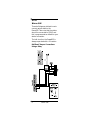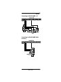
1
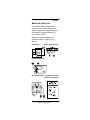
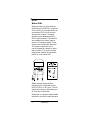
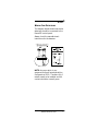
Quick Guide
to Power832
PC5015
For more detailed information, please refer to
the Installation Manual and Programming
Worksheets.
Features
Table of Contents
Features ................................................. 1
Installation ............................................. 2
Installing the Power832 Control
Panel ........................................... 2
Wiring .................................................... 4
Wiring Keybus .............................. 4
Wiring 24-hr Devices .................... 5
Wiring PIRs .................................. 6
Wiring Fire Detectors ................... 7
Wiring SAB .................................. 8
Telephones ........................................... 10
Telephone Connections .............. 10
Power Up .............................................. 11
Initial Start Up ............................ 11
Common Start-Up Problems ...... 14
[*] Commands ..................................... 15
Power832 Expansion Flowchart ............ 16
Clearing Troubles ................................. 20
Module Guide ....................................... 23
Default Settings .................................... 24
Basic Programming ............................. 25
Translation ........................................... 29
The Language Barrier ................ 29
Using the Big Books ............................. 30
i36
Features
Features
Features
•
•
•
•
•
•
•
•
•
•
•
•
•
•
•
•
•
•
•
•
8 on-board zones
Expandable to 32 zones via 8
zone modules or wireless module
Supports up to 8 keypads
LED and LCD versions available
Up to 14 programmable outputs
All modules connected via 4-wire
Keybus
Uses normal alarm cable
Modules can be wired star or
daisy chain
All modules are fully supervised
256 event log
20+ zone types
Zones can be configured as NC,
SEOL or DEOL
8 zone attributes
2 true partitions
Common zones
Built-in multi-channel
communicator
Selectable comms formats
including Contact ID, SIA, 4-8-1
and Pager
Built-in modem for downloading
Remote engineering (via DLS)
2 Separate entry delays
Technical Support:
01482 322228/329911
Features
1
Features
Installation
Installing the Power832
Control Panel
The following steps should be carried
out in the order described below. This
will help reduce the overall installation
time.
Before carrying out any installation
work, it is always advisable to walk the
site and check the proposed location
of all the equipment you are intending
to install.
1. Run all cables from the location
of the detectors or modules back
to the main control panel or zone
expander units.
2. Insert the five nylon studs through
the back of the steel cabinet and
mount the cabinet on the wall. Fit
the control panel to the wall.
Insert the PC5015 PCB onto the
nylon studs until it locks into
place. Connect the two yellow
leads from the transformer into
the AC– in terminals on the PCB.
3. Fit the remote keypad, detectors
and internal & external sounders
in the areas described on the
specification.
4. Connect the mains cable to the
unswitched fuse spur and to the
control panel. DO NOT POWER
UP YET.
Power832 Control Panel
2 Installing theFeatures
Installation
5. Connect all modules on the
Keybus using STAR or DAISY
chain, red to red, black to black,
yellow to yellow and green to
green.
6. Connect all detection devices.
7. Connect the external sounder.
8. Insert the lid tamper and wire to
the control panel.
9. Fit the battery into the control
panel and connect the RED to
RED and BLACK to BLACK.
10. Connect the control panel to the
telephone line if monitoring or
upload/download is required.
11. Close the cabinet lid securely and
apply mains power to the unit.
12. Programme the control panel
NOTE: The default settings of the
control panel will be suitable for
most installations and the minimum of additional programming
will therefore be required.
13. Test the unit fully using Walktest
and communications if programmed.
Installing the Power832 Control Panel 3
Features
Wiring
Wiring Keybus
The Keybus wiring is the most important part of the installation process of
the Power832 and its associated
modules. The Keybus is a simple 4wire connection between the main
control panel and all modules connected to it. Do not use the Keybus
cable for connection to any other
devices: e.g., do not try to repower
detectors or devices using the extra
cores in a multi core cable. The
Keybus is coloured RED, BLACK,
YELLOW, GREEN. All units can be
connected to the Keybus in a star or
daisy chain formation. All modules
have clearly marked terminal blocks
that identify the Keybus connection.
The Keybus must be run in a minimum of 22- gauge, non shielded wire
(use shielded wire for intercom
stations only). Any module can be
connected anywhere to the Keybus
provided it is not more than 305
meters from the control panel.
4
Wiring
Keybus
Features
Wiring
Wiring 24-hr Devices
The diagram below shows how to
connect door contacts, break glass
detectors and panic attack buttons to
the Power832 using double end of
line resistors (DEOL).
Always follow the manufacturer’s
instructions when installing such
devices.
Panic Button
Door Contact (surface)
Break Glass Detector
Door Contact (flush)
5K6 Resistor Used in
All DEOL Connections
Wiring 24-hr Devices
5
Wiring
Wiring PIRs
Although zones can be be wired as
double end of line (DEOL), single end
of line (SEOL) or normally closed, we
recommend DEOL for all intrusion
sensors and contacts. The panel
actually comes defaulted as SEOL.
DEOL means that two 5.6K resistors
are installed at the sensor head as
shown in the diagram below. These
resistors are included with the panel.
The resistors measure a loss in
current caused by a tamper or other
fault condition. The result is greater
integrity and reduced wiring requirements. (4 core instead of 6)
Always repower the panel when
changing zone configurations from
DEOL to SEOL or NC loops. This will
involve disconnecting the battery and
AC from the control panel.
Remember, on repower, always enable
supervision and set the time and date.
6
Wiring PIRs
Wiring
Wiring Fire Detectors
The diagram below shows how smoke
detectors should be connected to the
Power832 control panel.
Always check the manufacturer’s
instructions for the detector.
NOTE: Any zone which is programmed as fire will automatically be
configured as SEOL. Therefore only 1
resistor needs to be installed and the
contact should be normally open.
Wiring Fire Detectors
7
Wiring
Wiring SAB
These bell diagrams indicate how to
connect various bells to the
Power832. Take note that the strobe
should be connected to PGM 2 and
this is programmed as default for your
strobe connection.
The bell circuit on the Power832 is
always supervised with a 1K resistor.
Bell/Panel Tamper Connections
Using a Relay
8
Wiring SAB
Wiring
Connecting A NOVAGUARD 2+T
Connecting A NOVAGUARD Delta
Economy
Wiring SAB
9
Features
Telephones
Telephone Connections
The Power832 is a powerful communications device and it is important
that you make the correct connections to the telephone line. The line
may be connected in different ways
for different applications.
Connecting the Phone Line with
Escort and Intercom
NOTE: The control panel should
always be the first device on the line.
This is to ensure various features work
correctly such as line seizure.
10
Telephone
Connections
Features
Features
Power Up
Initial Start Up
Before turning on the mains power,
make sure that all electrical connections are completed and all devices
are connected correctly to the main
PCB. The two YELLOW leads on the
transformer should be securely
terminated in the two terminals
marked AC.
Before turning ON the mains power,
ensure you have the battery connected to the control panel, then
insert the fuse into the terminal block
using the holder provided.
The control panel keypad will beep on
power up and the LCD version shows
the software version on the screen.
This is normal.
The Keybus voltage should read 12.0
volts to 13.8 volts in the normal state.
If a low Keybus error occurs, the
reading should be around 11.0 volts
to 11.5 volts. A critical condition on
the Keybus is anything between 10.0
volts and 10.3 volts. This will result in
a shutdown.
If you have a Keybus problem, you
should carry out the following: check
the connections on all Keybusconnected devices; check the cable
run distance; check that cable type is
Initial Start Up
11
Power Up
correct; and check voltage at the far
end. Disconnect furthest item on
Keybus and work back measuring
voltage. The panel will provide around
550mA of current for powering
modules and detection devices.
Always keep this in mind when expanding a system. If you need more
power, you should use a PC5204
module. This will provide an extra
1.0Amp of power.
You may be using some additional
modules with the Power832. Always
repower the control panel after adding
them onto the system. You will also
need to enable supervision, [*][8]
[5015][902]. Wait one minute then
enter [903]. The added modules
should now be displayed. Push the
[#] key when you have finished. If a
unit is not displayed in the [903],
check all of the connections for the
unit.
12
Initial Start Up
Power Up
Ready Armed Trouble
If the keypad is showing the orange
“Trouble” LED, there is a problem
with the panel. To find more detail on
the problem, press [*][2]. The default
Master Code is [1234] and the default
engineer code is [5015].
Initial Start Up
13
Power Up
Common Start-Up Problems
Loss of Clock – Panel needs to have
time and date set. To do this press
[*][6][Master Code][1], then enter
time/date as: HH:MM/MM/DD/YY.
TLM – Panel has no phone line
connected. To cure this fault, enter
programming [*][8][Engineer Code]
and enter section 015. Turn off option
7.
Zone Fault/Tamper – Incorrect zone
supervision selected. Enter programming [*][8][Engineer Code] and enter
section 013. Select correct options
from 1 and 2.
14
Common Start-Up Problems
Features
[*] Commands
The Power832 allows for the access of
information and outputs by using [*]
commands. These commands are
very similar on all DSC products.
[*][1] Zone Bypass Features
Enter [*][1]. Bypass light flash. Enter
two-digit zone number to bypass.
Zone light ON; push [#] key.
[*][2] Display Troubles
Press [*][2] to view trouble conditions.
Keypad will flash trouble light and
LED keypad zone light(s) to indicate
troubles. See Installation Manual,
page 13 for detailed explanation.
[*][3] Alarm Memory
Press [*][3]; the keypad will flash the
memory light and light up zones
according to alarms or tampers that
occurred during last armed period. To
clear, arm and disarm system.
[*][4] Door Chime ON/OFF
Press [*][4] to turn on chime. The
keypad will beep three times to
indicate ON and one long beep to
indicate it is OFF. If you have a
problem with chime on other zones
check the zone attributes and turn
OFF option 03.
[*] Commands
15
Features
Power832 Expansion Flowchart
16
Features
Power832 Expansion Flowchart
Features
Power832 Expansion Flowchart
Power832 Expansion Flowchart
17
[*] Commands
[*][5] Programming Access Codes
Press [*][5][Master Code]. The keypad
will flash the program light and turn
on the zone light for any codes
already programmed.
Enter the two-digit user number for
the code you want to program. The
corresponding zone light will flash.
Enter the four-digit code. The zone
light will then turn on steady. Do not
use [*] or [#] in user codes. Push the
[#] when you have finished. To assign
codes to partitions, press [*][5][Master code][9]. Enter the two-digit user
number. Lights one to four will be on
or off. If you want the user to be able
to access partition 1, turn 1 ON;
partition 2, turn 2 ON; to be able to
bypass 3, turn 3 ON. Push [#] when
finished.
[*][6] User Functions
Press [*][6][Master Code]
[*] to view event buffer;
[1] to set the time and date;
[4] for system test;
[5] to enable DLS window.
18
[*] Commands
[*] Commands
[*][7] Output Functions
[*][7][Access Code] to activate Utility
Output.
[*][7][2] to activate smoke detector or
shock sensor reset.
[*][8] Access to Engineering Functions
Press [*][8][Engineer Code] to enter
engineering functions (Installation
Manual, page 19).
[*][9] Arming without Entry Delay
Press [*][9][Access Code] the panel
will remove the entry delay from the
partition.
[*][0] Quick Arm/Quick Exit
Press [*][0] to quick arm the system.
Ensure section 013, light 4, is programmed ON for this to work. Press
[*][0] when system armed to give
quick exit without unsetting the
system. Momentary bypass.
[*] Commands
19
Features
Clearing Troubles
If the orange “Trouble” LED is lit,
there is trouble on the system. To
view, press [*][2].
The trouble condition will be displayed on the LCD keypad. Scroll
through the display using the [<][>]
keys to see if more than one trouble
condition is present.
On the LED keypads, the trouble condition will be indicated by a lit LED zone.
NOTE: Zone 1 LED gives a further
sub-menu of troubles. Therefore, if [1]
is lit, push [1] again for specific
information on the trouble condition.
Keypad Display After Pressing [*][2]
LED Lit LCD Display
[2]
AC Failure
AC no longer supplied to control
unit. To inhibit reporting of short
power-out durations, programme
delay in section [370].
[3]
Telephone Line Trouble
Telephone connection to control
panel reporting problem with
connection. Check telephone line
voltage and connection. Power
down with phone line connected.
20
Clearing
Troubles
Features
Clearing Troubles
[4]
Failure to Communicate
Panel unable to send information to
central station. Check telephone
line, telephone number of Central
Station, format and reporting
codes. Dial number from handset
and listen for tones to ensure
number correct.
[5]
Zone Fault
The trouble will be indicated if any
zone on the system is in a trouble
condition, i.e. if it could not send
an alarm to the panel if required to
do so. Press [5] to view the zone
number.
[6]
Zone Tamper
This condition will only be generated for zones with DEOL resistor
supervision. This trouble is generated when a tamper is present.
Press [6] whilst in trouble mode to
view zone with a tamper condition.
[7]
Device Low Battery
Generated when a wireless device
exhibits a low battery. Press [7]
again to view which devices have
low battery.
[8]
Loss of System Time
This condition occurs when the
control unit is powered up and the
internal clock has not been set up.
[*][6][Master Code][1] to put in new
date and time.
Clearing Troubles
21
[*] Commands
[1]
Further Sub-Menu of
Troubles
If [1] comes ON, push [1] again for
specific trouble present. LED lit
after pushing [1] again will indicate
type of trouble.
[1]
Low Battery
Check Battery. May be ON if battery
is below 11.5 volts.
[2]
Bell Circuit Trouble
Panel senses open condition on bell
circuit.
[3]
General System Troubles
Only generated if PC5204 or
PC5400 have fault conditions.
[4]
General System Tamper
Tamper on module. [*][6][Master
Code][*] to view which module is in
tamper via the event buffer.
[5]
General Supervisory
Trouble
Loss of communication with
module. [*][6][Master Code][*] to
view event buffer for details. Also try
[*][8][Engineer Code][902].
[7]
PC5204 Low Battery
[8]
PC5204 AC Failure
The panel constantly monitors itself
for several different “Trouble” conditions. If a trouble condition is present
the “Trouble” light will be on steady
and all the keypads will beep twice
every 10 seconds.
22
[*] Commands
Features
Module Guide
The following modules can be used
with the PC5015.
Keypads (Max. of 8 per system)
PC5508TZ – 8 Zone LED keypad
PC5532TZ – 32 Zone LED keypad
LCD5500TZ– LCD keypad
Zone Expansion (Max. of 3 per system)
PC5108
– 8 zone expander module
Output Modules
(Max. of 1 of each per system)
PC5208
PC5204
– 8 low current outputs (50mA)
– 4 high current outputs (1A)
Home Automation Control
(Max. 1 per system)
Escort5580 – Escort module
TW7223
– X-10 control unit
Device Control (Max. of 32 per system)
LM01
AM01
– Lamp module (10A)
– Appliance module (13A)
Audio Control (Max. of 1 per system)
PC5928
– Audio control PCB
Audio Intercom Stations
(Max. of 7 per system)
PC5921
– Indoor intercom unit
PC5921EXT– External door box unit
Wireless Modules
PC5132
– 32 zone wireless receiver
Serial Output Module
PC5400
– Printer output module
Module Guide
23
Features
Default Settings
001 Zone Definitions
Zone 1
01
Entry/Exit
Zone 2
25
Instant
Zone 3
03
Instant
Zone 4
03
Instant
Zone 5
03
Interior
Zone 6
03
interior
Zone 7
03
Interior
Zone 8
05
Interior
005 System Times
Entry Delay 1
030 Seconds
Entry Delay 2
045 Seconds
Exit Delay
030 Seconds
Bell Cut-Off
020 Minutes
006 Engineer Code
Default
5555
007 Master Code
Default
1234
013 First System Option Codes
Double End Of Line Resistors
164 Bell Delay
Default
24
000 Minutes
Default
Settings
Features
Features
Basic Programming
Now let’s look at how to change some
of the default settings listed on the
previous page. If you are using the
Power832 as a “bells only” system,
this could be the only programming
you need to do.
For example, let’s look at changing
the entry delay from default 30 seconds to 45 seconds. Entry delay is in
section 005, “System Times”, on
page 4 of the Programming
Worksheets. All entries in section 005
require 3 digits.
To get into engineering programming
mode you must press [*][8] followed
by your engineering code. At default
this will be [5015]. At this point the
keypad will display “Enter Section”
followed by three dashes. Enter the
three-digit number of the section you
want to program, in this case [005].
You will see the digits 030 displayed
indicating the default time of 30
seconds. Enter [045] for the new entry
delay time. If this is the only change
you want in section 005, you can now
press [#] to exit this section and save
the change. If you want to make
another change, (“Exit Delay”, for
example), then use the arrow keys
until 120 is displayed (the default
setting).
Basic Programming
25
Basic Programming
Once you press [#] to exit section
005, the keypad will again display
“Enter Section” followed by three
dashes.
If you want to make changes to
another section, then enter that new
section number. If you want to exit
engineering mode, simply press [#]
once more and the keypad will revert
to normal mode.
Let’s look at changing the default
setting of single end of line resistors
to our recommended double end of
line resistors.
Open the Programming Worksheets
to page 6, and find section 013, First
System Option Code; section 013 is a
toggle option section. Section 013 will
be displayed on the LCD keypad as 2
lines, the first line displays “Toggle
Option” and the second line displays
which options are toggled “ON” or
“OFF”. If a number appears, that
option is “ON”. If a dash is displayed it
means that option is “OFF”. If you are
using the LED keypad this will be
illustrated by the zone LEDs “ON” or
“OFF”. We see that option 2 is “OFF”
because we see a dash, not a number.
Looking at section 013 in the
worksheets we see option 2 “OFF” in
section 013. This means that the
panel is set up for single end of line
resistors. If the option were “ON”, the
number 2 would appear and the panel
would be set for double end of line
resistors.
26
Basic Programming
Basic Programming
To toggle options “ON” or “OFF”
press the corresponding number on
the keypad. Press [2] and the dash is
replaced by the number, indicating
the option is now “ON”. Press [2]
again and the number is replaced with
a dash, indicating the option is now
“OFF”.
Go through each of the options in the
section and determine if the option
should be “ON” or “OFF”. Once all
the options are selected correctly,
press the [#] key.
The keypad again displays “Enter
Section” followed by the three dashes.
To exit from engineer mode simply
press the [#] once more and the
keypad will revert to normal mode.
That’s all you need to get you started
programming the Power832 control
panel.
For complete details of all programming options, refer to the Installation
Manual.
Basic Programming
27
Basic Programming
Programming Examples:
Using a LCD keypad
28
Basic Programming
Features
Translation
The Language Barrier
(01) Delay 1 = Final Exit 1
(02) Delay 2 = Final Exit 2
(03) Instant = Normal Zone
(05) Interior Stay/Away = (Part Set)
Zone will be omitted if no Final exit
zone is activated. Zone arms if final
exit activated.
(06) Delay Stay/Away zone = Always
gives entry delay.
(25) Interior Delay = Entry Route/
Walk Through for domestic installations. Use for Hall PIR. In the Stay
Armed mode, this zone will give entry
delay when activated.
(04) Interior = Entry Route/Walk
Through for commercial installations
only. This zone type will not give an
entry delay when activated in Stay
Armed mode.
(27) Push to Set = Push to Set must
be double end of line resistors. Can
be o/c device but set to Force Arm,
display will read secure system or
enter code to set.
Another term that you may not be
fully familiar with is “Swinger Shut
Down”. This feature is a false alarm
feature and is used to control the
number of times a signal is transmitted to the central station in a given set
condition. This is zone-linked and
defaulted to three transmissions per
zone. What this means is that if a zone
goes faulty and keeps triggering the
communicator, the transmission will
only be sent a maximum of three
times.
The Language Barrier
29
Features
Using
the Big Books
How to use the Installation Manual
and Programming Worksheets included with this panel:
The Programming Worksheets and
Installation Manual that accompany
the Power832 may appear daunting to
the first time user. However, once you
understand their structure and how to
find your way through them, you’ll
wonder what all the fuss was about!
You will find inside the control panel
three manuals: one named Installation Manual, one named Programming Worksheets and the third
named Instruction Manual.
Please take out the Installation
Manual.
Look at the Installation Manual;
turning the first page, you should see
the Table of Contents. In the Table of
Contents, you will see that the manual
is broken up into five major sections.
Section 1 is the basic overview of the
panel specifications including AUX,
Bell and PGM output current ratings,
battery and transformer requirements
and a quick description of some of
the more common features. Section 1
also includes a list of all additional
modules available with a brief description of what each module will do.
30
Using
the Big Books
Features
Using the Big Books
Section 2 refers to wiring the control
panel, including a description of the
main panel terminal strip, the connection and operation of the Keybus,
current ratings of modules, module
supervision and zone wiring.
Section 3 is a summary of all the user
keypad commands including arming,
disarming, auto bypass and all the
keypad commands. Also included is a
description of the operation of the
function keys and partition and global
keypads.
Section 4 is simply a description of
how to programme the panel.
Section 5 is broken down into subsections. Each contains a description of
how a particular feature works with
certain words in the description in
bold print. These bold-printed words
are the options that you need to
programme in order to have the
features work appropriately.
Now take the Programming
Worksheets from the box. Lay the two
manuals out side by side. Open the
Programming Worksheets to page 6
and the Installation Manual to page
32. In the Programming Worksheets
beside every programme item is a
section number reference. These
numbers relate to the Installation
Manual sections.
Using the Big Books
31
Using the Big Books
For example, you may not be sure
what “TLM Enable” means in programming section 15. Beside the
option number is a reference number
(in this case 5.11). If you open the
Installation Manual at section 5.11
(page 32), you will see that TLM
stands for Telephone Line Monitoring.
There are several options that require
programming for the telephone line
monitor feature. These are
summarised at the end of the description and include which section the
option can be programmed in.
The summary of programme options
is also a good troubleshooting tool.
For example, if you are having difficulty getting the panel to send a test
transmission, look this feature up in
the Installation Manual. Refer to the
summary and make sure you have
programmed all the required information. If you think you missed an item,
the summary will tell you exactly what
programming section you need to
look at to check the item.
The third book named Instruction
Manual should be given to the client
or on-site manager.
For more detailed information, please
refer to the Installation Manual and
Programming Worksheets.
32
Using the Big Books
Features
Technical Support:
01482 322228/329911
33
Unit C51
Winfrith Technology Centre
Winfrith Newburgh
Dorchester
DT2 8DH
Telephone
01305 851700
Fax
01305 851660
Email: [email protected]
Web-Site: www.dscuk.co.uk
Unit 21
Hull Business Centre
Guildhall Road
Hull HU1 1HJ
Technical Support
Telephone
01482 322228/329911
Fax
01482 222262
Printed in Canada
29003975 R002