1
Comfort Installation Manual
Section 1 General Information . . . . . . . . . . . . . . . . . . . . . . . . . . . . 8
Specifications . . . . . . . . . . . . . . . . . . . . . . . . . . . . . . . . . . . . . . . . . . . . . . 8
Ordering Information - Products and Accessories . . . . . . . . . 11
Year 2000 Compliance Statement . . . . . . . . . . . . . . . . . . . . . . . . 12
What do I read first? . . . . . . . . . . . . . . . . . . . . . . . . . . . . . . . . . . . . . . 12
Manuals for Installers . . . . . . . . . . . . . . . . . . . . . . . . . . . . . . . . . . . . . 12
Manuals for Users . . . . . . . . . . . . . . . . . . . . . . . . . . . . . . . . . . . . . . . . . 13
Design Considerations and Applications . . . . . . . . . . . . . . . . . . 14
Section 2 Installation . . . . . . . . . . . . . . . . . . . . . . . . . . . . . . . . . . . . 20
ICs . . . . . . . . . . . . . . . . . . . . . . . . . . . . . . . . . . . . . . . . . . . . . . . . . . . . . . . . 20
Connections . . . . . . . . . . . . . . . . . . . . . . . . . . . . . . . . . . . . . . . . . . . . . . . 20
Schematic Block Diagram - Comfort System . . . . . . . . . . . . . 21
Schematic Diagram - Peripherals . . . . . . . . . . . . . . . . . . . . . . . . . 22
PCB Layout . . . . . . . . . . . . . . . . . . . . . . . . . . . . . . . . . . . . . . . . . . . . . . . . 23
Jumper Settings and Adjustments . . . . . . . . . . . . . . . . . . . . . . . . 24
Location of Panel . . . . . . . . . . . . . . . . . . . . . . . . . . . . . . . . . . . . . . . . . . 24
Panel Mounting . . . . . . . . . . . . . . . . . . . . . . . . . . . . . . . . . . . . . . . . . . . 24
Mains Supply - 230 VAC . . . . . . . . . . . . . . . . . . . . . . . . . . . . . . . . . . 25
Back-Up Battery Supply - 7Ah (JP2) . . . . . . . . . . . . . . . . . . . . . . 25
Factory Restart . . . . . . . . . . . . . . . . . . . . . . . . . . . . . . . . . . . . . . . . . . . . 26
Cable Routing / Requirements . . . . . . . . . . . . . . . . . . . . . . . . . . . 27
Keypad and Door Stations . . . . . . . . . . . . . . . . . . . . . . . . . . . . . . . . 28
Speaker and Strobe (JP10) . . . . . . . . . . . . . . . . . . . . . . . . . . . . . . . 31
Siren / Bellbox Connections (JP9) . . . . . . . . . . . . . . . . . . . . . . . . 31
Telephone Connections . . . . . . . . . . . . . . . . . . . . . . . . . . . . . . . . . . . 33
BT Highway (ISDN 2e)
.....................................
34
Parallel Phone Connections . . . . . . . . . . . . . . . . . . . . . . . . . . . . . . . . . .
34
Connection to extension of PABX . . . . . . . . . . . . . . . . . . . . . . . . . . . . .
35
36
39
40
41
Zone Input Terminals Z1- Z8 (JP3 - JP6) . . . . . . . . . . . . . . . . .
Tamper Input (J4) . . . . . . . . . . . . . . . . . . . . . . . . . . . . . . . . . . . . . . . .
‘Negative Applied’ Detectors . . . . . . . . . . . . . . . . . . . . . . . . . . . . . .
Output Terminals OP1 - OP8 (JP11-JP14) . . . . . . . . . . . . . . . . .
Connection to External Relays
...............................
41
Using AC Relays for Feedback
...............................
41
Connection to Visible or Infrared LEDs
........................
42
..............................
...........
43
44
Arming Response . . . . . . . . . . . . . . . . . . . . . . . . . . . . . . . . . . . . . . . . . .
44
False Alarm on Disarming . . . . . . . . . . . . . . . . . . . . . . . . . . . . . . . . . . .
44
Using Lamps for Output Status
12V Auxiliary Supply Outputs (12V and S12V)
1
Comfort Installation Manual
Using 12V Supplementary Supplies . . . . . . . . . . . . . . . . . . . . . .
Connection to RedCARE or DualCom . . . . . . . . . . . . . . . . . . . . . .
Reporting Comfort Line Fault . . . . . . . . . . . . . . . . . . . . . . . . . . .
Remote Reset - RedCARE /DualCom . . . . . . . . . . . . . . . . . . . . . .
Resettable Fuses (PTC) . . . . . . . . . . . . . . . . . . . . . . . . . . . . . . . . . . .
X10 Connection (MJ3) . . . . . . . . . . . . . . . . . . . . . . . . . . . . . . . . . . . .
Connection to Local Expansion Modules
...............
Power-On Checklist . . . . . . . . . . . . . . . . . . . . . . . . . . . . . . . . . . . . . . .
Section 3 Programming . . . . . . . . . . . . . . . . . . . . . . . . . . . . . . . . . .
Comfort Security System . . . . . . . . . . . . . . . . . . . . . . . . . . . . . . . . .
Home Automation - Responses and Actions . . . . . . . . . . . . . .
Zone-Activated Responses
Alarm-Activated Responses
45
46
48
48
49
50
51
53
54
54
55
..................................
55
.................................
55
Time Programs . . . . . . . . . . . . . . . . . . . . . . . . . . . . . . . . . . . . . . . . . . . .
55
Holiday Programs . . . . . . . . . . . . . . . . . . . . . . . . . . . . . . . . . . . . . . . . . .
56
Security Mode Responses
..................................
56
Home Control Menu . . . . . . . . . . . . . . . . . . . . . . . . . . . . . . . . . . . . . . . .
57
Keypad Responses . . . . . . . . . . . . . . . . . . . . . . . . . . . . . . . . . . . . . . . . .
57
CS-Xpress PC Software / UCM01 Interface Installation . . . 58
Remote Signalling Requirements for Police Response
(UK) . . . . . . . . . . . . . . . . . . . . . . . . . . . . . . . . . . . . . . . . . . . . . . . . . . . . . . . 59
Engineer Reset . . . . . . . . . . . . . . . . . . . . . . . . . . . . . . . . . . . . . . . . . . . .
59
Remote Reset of the system
................................
59
Exit Terminator / Door Station Button . . . . . . . . . . . . . . . . . . . . . . . . .
60
Bell Delay (Siren Delay)
60
....................................
Abort / Open and Close signalling
............................
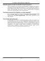
Program and Engineer Menus . . . . . . . . . . . . . . . . . . . . . . . . . . . . .
Entering Engineer Menu . . . . . . . . . . . . . . . . . . . . . . . . . . . . . . . . . . .
How to use the Voice Menus . . . . . . . . . . . . . . . . . . . . . . . . . . . . .
Using the Program Worksheet . . . . . . . . . . . . . . . . . . . . . . . . . . . .
Number of Keypads and Door Stations
System Control Number
Table 1 - System Settings
60
61
61
62
63
........................
63
....................................
63
..................................
63
Table 2 - Status Indicator Output Assignments
.................
64
................
64
Table 4 - Zone Settings (Engineer Menu 1) . . . . . . . . . . . . . . . . . . . .
64
Table 3 - Away Arming Method (Location 1692)
2
Comfort Installation Manual
Zone Types . . . . . . . . . . . . . . . . . . . . . . . . . . . . . . . . . . . . . . . . . . . . . . .
64
Table 8 - Zone Types - Security Mode Assignments
.............
65
Instant/Alert/Perimeter Zoning for False Alarm Filtering . . . . . . . . . .
65
Table 9 - Zone Types (Alarm Type Assignments)
...............
66
................
67
Selecting a Zone Type . . . . . . . . . . . . . . . . . . . . . . . . . . . . . . . . . . . . . .
67
Customising Zone Behaviour with Responses . . . . . . . . . . . . . . . . . . .
71
Table 12 - Phone Settings (Engineer Menu 4,1)
................
73
........................
73
Table 10 - Zone Types - Miscellaneous Settings
Table 13 - Monitoring Station Settings
Table 15 - Entry/Exit Time (Engineer Menu 4,2)
................
73
...............
74
.....................
74
....................
75
Table 21 - Other Dialout Parameters . . . . . . . . . . . . . . . . . . . . . . . . . .
76
Table 22 - Siren Types
.....................................
76
....................................
76
...................................
77
Table 25 - Siren Type (Output Settings) . . . . . . . . . . . . . . . . . . . . . . .
77
Table 26 - Control Menu (Engineer Menu 3,1)
..................
77
......................
79
Table 28 - Time Programs (Engineer Menu 3,3) . . . . . . . . . . . . . . . . .
79
Table 29 - Holiday Program (Engineer Menu 3,4)
80
Table 16 - Security Options (Engineer Menu 4,3)
Table 17 - General (Non-detector) Alarms
Table 18 - Alarm Types (Engineer Menu 2)
Table 23 - Sound Types
Table 24 - Siren Duration
Table 27 - Holidays (Engineer Menu 3,2)
...............
Table 30 - Security Mode Response (Eng Menu 3,5)
Table 31 - Event Triggered Responses
.............
80
........................
80
Table 32 - X10 Received Codes Responses
....................
80
Table 33 - Responses (Engineer Menu 3,6)
....................
81
...........................
81
Table 34 - Other Location Changes
Table 35 - Location 39 and 40 Flag Settings
Table 37 - User Timers
...................
81
.....................................
82
Table 38 - User Authorisation Settings
........................
82
Table 39 - Control Station Menu (Eng Menu 4,4) . . . . . . . . . . . . . . . .
82
Action Codes for Keypads . . . . . . . . . . . . . . . . . . . . . . . . . . . . . . . . . . .
82
3
Comfort Installation Manual
Door Station Programming . . . . . . . . . . . . . . . . . . . . . . . . . . . . . . . . 84
Advanced Programming . . . . . . . . . . . . . . . . . . . . . . . . . . . . . . . . . . . 84
Preventing the two pulses on the siren when Away Armed . . . . . . . .
84
Changing the Siren duration for any Alarm
84
....................
Resetting Latched Detectors After Alarm (v4.101)
..............
85
Programming Entry door to cause an instant alarm (not delay) in
Night Mode . . . . . . . . . . . . . . . . . . . . . . . . . . . . . . . . . . . . . . . . . . . . . .
85
Disabling a recurring zone activation (swinger shutdown)
........
86
Programming a Bell Delay
..................................
86
Programming a Dial Delay
..................................
86
Disabling dialouts in Night (and Day) Mode
....................
86
Omitting Zones (v4.96) . . . . . . . . . . . . . . . . . . . . . . . . . . . . . . . . . . . . .
87
Reporting Bypassed Zones . . . . . . . . . . . . . . . . . . . . . . . . . . . . . . . . . .
87
Playing a warning message on a Keypad or Door Station . . . . . . . . .
87
Programming a Vibration/Shock Analyzer . . . . . . . . . . . . . . . . . . . . . .
87
Programming a zone for Entry Delay in Night Mode
Daylight Savings Clock Adjustment (DST) . . . . . . . . . . . . . . .
Section 4 Testing and Commissioning . . . . . . . . . . . . . . . . . .
Section 5 Troubleshooting . . . . . . . . . . . . . . . . . . . . . . . . . . . . . . . .
Troubleshooting Kit . . . . . . . . . . . . . . . . . . . . . . . . . . . . . . . . . . . . . . .
Red/Green LEDs Initialisation Sequence Wrong . . . . . . . . . .
Keypad/ Door Station Problems . . . . . . . . . . . . . . . . . . . . . . . . . . .
Phone Problems . . . . . . . . . . . . . . . . . . . . . . . . . . . . . . . . . . . . . . . . . . .
87
88
89
91
91
91
92
94
Cannot Sign in on Local Phone . . . . . . . . . . . . . . . . . . . . . . . . . . . . . . .
94
"Phone Trouble" . . . . . . . . . . . . . . . . . . . . . . . . . . . . . . . . . . . . . . . . . . .
94
Parallel Phones . . . . . . . . . . . . . . . . . . . . . . . . . . . . . . . . . . . . . . . . . . . .
95
Customer has their own Answering Machine
...................
95
..........................
95
Customer’s Caller ID Does not work
.............
Special Telecom Services (e.g. Call Forwarding and Voice Mail)
. . . 95
Cannot dial out successfully . . . . . . . . . . . . . . . . . . . . . . . . . . . . . . 96
Tracing False Alarms . . . . . . . . . . . . . . . . . . . . . . . . . . . . . . . . . . . . . . 96
Use Event Log
............................................
96
False Alarm on Disarming . . . . . . . . . . . . . . . . . . . . . . . . . . . . . . . . . . .
97
97
Zone Troubles
.............................................
How to recover lost User Codes
4
..............................
97
Comfort Installation Manual
Is the Siren Duration restarted during Alarm by
new zone
activations? . . . . . . . . . . . . . . . . . . . . . . . . . . . . . . . . . . . . . . . . . . . . . .
97
Section 6 Engineer Menu . . . . . . . . . . . . . . . . . . . . . . . . . . . . . . . . . 99
Zone(1) . . . . . . . . . . . . . . . . . . . . . . . . . . . . . . . . . . . . . . . . . . . . . . . . . . . 99
Zone Description (1,1)
99
10
............................................ 0
10
Entry Path (1,3)
........................................... 0
10
Zone On Response (1,5)
.................................... 0
10
Zone Off Response (1,6)
.................................... 1
Alarm (2)
10
.................................................. 2
10
Dial Settings (2,1)
......................................... 2
10
Dial Settings (2,1,1)
........................................ 2
10
Dial Delay (2,1,2)
.......................................... 3
10
Alarm Report Code (2,1,3)
.................................. 3
10
Alarm Restore Code (2,1,4)
................................. 4
10
Monitoring Station Code (2,1,6)
............................... 4
10
Alarm Response (2,2)
...................................... 5
10
Description (2,3)
........................................... 5
10
Strobe (2,4)
............................................... 5
10
Siren Type (2,5)
........................................... 5
10
Trouble Arm (2,7)
.......................................... 6
10
Alarm State (2,8)
........................................... 6
Control (3)
10
................................................. 6
.....................................
Zone Type (1,2)
5
Comfort Installation Manual
10
6
10
Description (3,1,1)
......................................... 7
10
Control Action Key (3,1,2)
................................... 7
10
Control Action Words (3,1,2,1)
............................... 7
10
Control Action Response (3,1,2,2)
............................. 8
11
Holiday Settings (3,2)
....................................... 0
11
Time Program (3,3)
......................................... 1
11
Day of Week (3,3,1)
........................................ 1
11
Change Time (3,3,2)
........................................ 2
11
Response (3,3,3)
........................................... 2
11
Holiday Program (3,4)
....................................... 2
11
Holiday Program - Start Time (3,4,1)
.......................... 3
11
Holiday Program - Hours (3,4,2)
.............................. 3
11
Holiday Program - ON Response (3,4,3)
........................ 3
11
Holiday Program - OFF Response (3,4,4)
....................... 3
11
Security Mode Response (3,5)
................................ 4
11
Response (3,6)
............................................ 4
Security (4)
11
................................................ 6
11
Phone Settings (4,1)
....................................... 6
11
Monitoring Station Code (4,1,4,1)
............................ 7
11
Monitoring Station Type (4,1,4,2)
............................ 7
Control Menu (3,1)
.........................................
6
Comfort Installation Manual
11
8
11
Monitoring Station Voice Station Option (4,1,4,4)
............... 8
11
Entry/Exit Time (4,2)
....................................... 9
11
Entry Time (4,2,0)
......................................... 9
11
Exit Time (4,2,1)
........................................... 9
12
Entry Warning Time (4,2,2)
.................................. 0
12
Night Exit Time (4,2,3)
...................................... 0
12
Security Options (4,3)
...................................... 0
12
Force Arm Setting (4,3,1)
................................... 0
12
Siren Reverse (4,3,3)
....................................... 1
12
Control Station (4,4)
........................................ 1
Event Log (5,1)
12
........................................... 2
Printing the Event Log
12
..................................... 3
12
Erase Event Log (5,0)
...................................... 4
Change Sign-in Code (6)
12
................................... 4
System (7)
12
................................................. 5
12
Pulse Dial Option (7,1)
...................................... 5
12
PABX option (7,2)
.......................................... 5
12
Star Menu (7,4)
........................................... 6
Test (8)
12
.................................................... 7
12
Battery Check (8,1)
........................................ 7
Monitoring Station - Change Phone Number (4,1,4,3)
............
7
Comfort Installation Manual
12
7
12
Dial Test (8,3)
............................................. 8
12
Siren Test (8,4)
............................................ 8
12
Strobe Test (8,5)
........................................... 8
Engineer Test Mode (8,6) - use for keypad and doorphone tampers 12
. 8
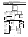
Engineer Menu Flowchart
12
................................. 9
Technical Support
13
.......................................... 0
Security Check (8,2)
........................................
Revised January 13th 2001 for PCB Rev E
8
Comfort Installation Manual
SECTION 1
GENERAL INFORMATION
Specifications
Zones
w
8 fully programmable zones on Control Panel, expandable to 16 or 24
with Local Expansion Module (LEM) and 64 with Remote Expansion
Module (SEP02)
Each zone configurable for 0 or 2 end-of-line resistors
w
Up to 32 predefined Zone types to simplify zone configuration
w
Surge/Over voltage protection for each zone
w
Power Supply
w
16.5 V 40VA Class II
w
w
Minimum Standby Battery requirement: 12V, 7 AH sealed lead-acid
battery for 4 hour standby. (UL985: One 7 AH battery for 24 hour
standby with 200 mA auxiliary current, or two 7AH batteries for 24
hour standby with 400 mA auxiliary current). Reverse protection for
battery.
1.5 A regulated DC supply with Resettable Fuse protection
w
Supervised for Mains failure and low battery
w
CPU Dimensions: h= 350 mm, w= 362 mm, d= 90 mm, weight 5 kg
boxed.
Auxiliary Supply Outputs
w
12V unswitched supply
w
12V switched supply (automatically reset when disarmed)
w
Note: Both switched and unswitched auxiliary supplies and 8 Outputs
have a combined continuous current limit of 1A. (500 mA for UL
applications)
Alarm Outputs
w
Speaker Drive with 20 siren patterns
w
Siren Output with programmable siren pulse patterns
w
Strobe output (12v)
w
Combined Alarm Output current of 1.5 A max (with battery)
System Supervision
w
Low Battery
w
Mains failure
w
Telephone Line cut
w
Individual Zone tamper (open-circuit or short-wiring) with 2 end of line
resistors
Dedicated 24 hour Tamper input (used for cabinet and siren tamper)
w
9
Comfort Installation Manual
Memory
w
w
Non-volatile memory maintains configuration during total removal of
power
Event log with 250 events which can be accessed remotely or locally.
Alarm Types
w
32 programmable alarm types including user-definable alarm types
w
Predefined alarm types include Intruder, Fire, Panic, Duress, Arm ,
Disarm etc. Each alarm type selects a siren pattern, telephone
combination, can trigger a user-defined response, which turns on/off
appliances, lights etc.. Each alarm type can be set to report to any
combination of the telephone numbers
Dialler / Digital Communicator
w
w
w
w
w
8 programmable telephone numbers. Each alarm type activation can be
programmed to dial to any combination of telephone numbers.
Each number can be assigned to Central station, voice phone, personal
pager, or recorded voice message.
Pager automatically displays system ID, alarm type and Zone or User
number (depending on the alarm type)
2 Central Monitoring station numbers with individual account numbers.
Digital communicator formats supported include all major pulse
formats (3x1, 4x1, 3x2, 4x2 at 10 pps, 20 pps and 40 pps), Contact
ID, Surgard. (This product has been tested by Underwriters
Laboratories with the Radionics Model 6400 receiver using 3-1 40 pps
and 4-2, 40 pps formats).
Home Automation Outputs
w
w
w
w
w
w
8 open collector outputs on main board, expandable to 16 with
Expansion module.
Each output can drive external relay or infrared LED for remote control
appliances. Relay Modules with 4 relays are available.
Selectable Pulsed or Steady output activation.
32 (FS18) or 25 (FS17) selectable infrared codes (air conditioners,
home entertainment) for any output.
Built-in X10 interface to PSC04 (110V 1 way) /PSC05/ TW523 (110V 2
way)TW7223 (230V 2 way) module. (This feature has not been tested
by Underwriters Laboratories)
Over voltage and Surge-protected outputs.
Keypad / Door Station
w
Up to 4 Keypads / Door Stations per system (8 with auxiliary power
supply)
Keypad/Door Station current consumption : 15 mA (idle), 120 mA with
siren
Indicator LEDs: Home/Trouble, Armed/Alarm, Power Failure/Low
Battery, New Message, Microphone on.
Voice and siren sounds
w
Built-in microphone for recording, intercom and alarm verification
w
w
w
10
Comfort Installation Manual
w
Tamper switch (24 hour)
w
Loss of Communications Trouble alarm
w
Back-lit keys
w
Dimensions: h=158 mm, w= 90 mm, d= 35 mm, weight 300g boxed
Telephone Answering machine
w
Digital Answering machine with 10 minutes of recorded messages
w
8 programmable mailboxes with individual sign-in codes.
w
Recorded messages with individual time/date stamps.
w
Answering machine is accessible from any phone in the house.
w
Call screening option on Keypad
w
Recordable greeting message and user names for each mailbox.
w
Messages are automatically played back when the mailbox user signs
in, or may be accessed from any telephone. New messages can be
forwarded to a phone or pager for each mailbox.
Automatically erases the oldest saved message when a new message
is recorded and recording memory is full.
w
False Alarm Filtering Features
w
2 way voice on Keypad
w
Voice Alarm History with Date and Time of zone activation.
w
Voice Alarm Tracking in real time of activated zones
w
Alert zone types require activation of another zone to trigger a
confirmed alarm
Local alarm warning option for delay entry time-out prior to full alarm.
w
w
Open- or short-circuit zone condition can be signalled as a trouble
condition (when 2 end-of-line resistors are used)
Night Mode Delay zone setting.
w
Double sign-in of duress code required to generate duress alarm.
w
Sign-in Codes
w
w
16 user codes with individual authorisation for arm and disarm, local
and remote access, and disarm after alarm. First 8 user codes for
mailboxes
Engineer code for system and security settings.
11
Comfort Installation Manual
Emergency Menu
w
Quick activation of Fire and Panic using telephone or Keypad
Test Features
w
Battery Test - Immediate or at programmed intervals
w
Security Check (walk test) zone activation is announced on Keypad
w
w
Dial test - dials to all programmed telephone numbers, pagers, Central
Stations, audible on Keypad
Siren Test - Momentary activation
w
Strobe Test. - turns on and off the strobe.
w
Engineer Test Mode - allows engineer to work on the system without
causing alarms.
Event Log
w
250 (REV E)
w
Full voice log, with date/time stamp and voice description of events
w
Local or remote access.
w
Select 1st event, last event, previous event , next event , next day,
previous day for quick navigation.
Uploadable to PC using CS-Xpress for Windows 95/98/NT/W2000, may
be printed or saved
w
Other Features
w
Report disarm by children returning home (Home-Safe Response)
w
w
Door Station intercom with home or remote phones (requires Door
Station)
8 Voice Reminder Messages capable of dialout to pager and telephone.
w
Family Care Alarm to monitor inactivity.
w
16 Time Programs
w
8 Holiday programs
Ordering Information - Products and Accessories
w
Comfort 8001/E (Europe): 8001/US (USA) Central Processor within
steel enclosure, Accessory pack and User Manuals, fully tamper
protected, without Battery.
Accessory Pack AP01: Contains 8 x 4700 ohms, 8 x 2700 ohm EOL
Resistors, 8 x shunts (for Zone Headers JZ1 to JZ8), 10 x 3-way
Terminal Blocks (JP3-7, JP10-14), 2 x 2-way Terminal Blocks (JP8,9)
Battery Cable with battery lugs,
EN02 - Enclosure for 2 x 7AH batteries (for UL985)
w
w
w
HN02 - Battery Harness 2 ft (for UL985)
w
MN01 - User Manual
w
MN02- Installation Manual
w
MN03 - Applications Manual
w
TR1640 - UL-listedTransformer (16.5V, 40VA) manufactured by Macon,
Type ATW-1640 for US market, Transformer is within CPU for Europe.
12
Comfort Installation Manual
w
BT1270 - Battery 12V 7AH (Sealed Lead-Acid)
w
TB02 - 2 way Terminal Blocks
w
TB03 - 3 way Terminal Blocks
w
Model LEM01 - Local Expansion Module 8+8 (8 zones, 8 outputs)
w
EOL4.7K - 4.7K End-Of-Line insulated resistors
w
EOL2.7K - 2.7K End-Of-Line insulated Resistors
Items below have not been evaluated by Underwriters Laboratories:
w
KP01 - Keypad
w
KP02 - Keypad with Infrared Receiver (Comfort specific codes only)
w
DP01 - Polycarbonate Door Station
w
DP02 - Metal Door Station, flush mount or surface mount options
w
DM01 - Comfort Demonstration Briefcase
w
Model LEM02 - Local Expansion Module 8+0 (8 zones, 0 outputs)
w
Model LEM03 - Local Expansion Module 16+0 (16 zones, 0 outputs)
w
Infrared LEDs Kit (Infrared LED + 100 ohms 1W resistor)
w
12 V lamps
w
Model RLY01 Relay Module (4 relays)
w
Model CSM01 Current Sensor Module
w
Model LSM01 Light Sensor Module
w
Model ZTS01 Zone Test Switch
w
Model UCM01 RS232 Interface Module for PC communication
w
Model RGR01 Ringer Module
w
Model SEP02 Slave Expansion Panel
w
CS-Xpress for Windows 95/98/NT/W2000
Year 2000 Compliance Statement
Comfort is Year 2000 (Y2K) compliant, and has been so since the
product was first introduced. The system works correctly for all dates
up to 9999.
What do I read first?
We have found that placing all the information in one book makes it too
thick and means that you end up with three thumbs in various sections
of the book at once, so we felt it was easier if the relevant information
was spread across a few booklets for better organisation.
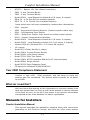
Manuals for Installers
Comfort Installation Manual
This manual describes the installation methods along with some basic
grounding on the Comfort Concept, also lists the voice menu options
13
Comfort Installation Manual
which are found after entering the Engineer Code and shows the
Flowchart for overall view
Keypad/ Door Station Installation Manual
This leaflet show how to connect and install the Keypad and Door
Stations to the Comfort control panel. The information is also found in
this manual.
Programming Worksheet
The worksheets are the place where you write down your customer
configuration and programming settings. We strongly recommend that
you do not attempt to install a system without using this worksheet as
it will make your programming much easier, and prevent you from
missing any settings. A detailed record of how each system is
configured is crucial for proper management. Also, keep it updated as
any future changes take place. If used properly it may ‘save your life’,
more than once.
Programming With Action Codes.
You can get the system up and running on the default settings, but its
likely you will want to do some of the clever things which attracted you
to Comfort in the first place. You will need a good grasp of Action Codes
and how they are used in Response.
Action codes are Comfort’s powerful customisation commands. These
are assembled into Responses (sometimes called “Macros”) to produce
multiple operations. They can be found in Table 33. Master these and
you can make your Comfort system do what no other system can. If
overwriting an existing Response, always check first that the Response
is not already being used by the system.
Defaults Manual
We try to provide a useful starting point for your Comfort Configuration,
this is called the default.cst file and is detailed in the Default Manual
Guide.
Applications Manual
The applications manual is a more in-depth guide to using action codes
and responses for use in customising a system.
Many of the
applications are not found in the default setup and must be entered into
the responses menu using the manual method via Engineer Menu 3,6 or
using CS-Xpress. This is updated constantly as new applications and
solutions are written. The Applications manual is is available On-line at:
www.comfort.org.uk/technical (password protected). You can apply for
a password at this address: www.comfort.org.uk/index4.html.
14
Comfort Installation Manual
Manuals for Users
Quick Start Guide
This guides the user on how to operate Comfort using the Keypad and
its function keys. very often this is the only thing the user needs to
read.
Users Reference Manual
This is a detailed users guide for those who want to make full use of
Comfort’s unique capabilities.
Design Considerations and Applications
Default Configuration and Responses
The default settings (default.CST) have been constructed to give a good
starting point for your security and automation system.
The default responses provide a broad selection of functions, they may
be viewed in table 33 of the Programming Worksheet. X10 commands
have been included. To make best use of these settings it is
recommended that Housecodes A are used for downstairs lights and
Housecodes B are used for upstairs lights. ‘L ‘has been used for outside
lights and ‘H’ has been set for heating. This segregation helps to
achieve functions such as flashing all the lights in an alarm condition or
to switch downstairs lights ‘off’ when Night Mode is selected.
Additionally, macros have been allocated within the default response to
simplify the process of linking many responses together when for eg.
Security Mode is required to cause more than one action such as switch
a light on, draw curtains and switch non-essential sockets back on.
Default also makes use of a light sensor on Zone 13 for lighting
sequences. Other macros have been assigned for certain Alarm Types,
Security Modes and the Doorbell action. There are also some default
Home Control functions such as Menu 6 (Alert Menu) which allows the
user to disable the chime and voice announcement from being triggered
by certain programmed zones.
Run Additional Cables
If you think you may require 6-core cable to a part of a building, run a
12-core instead, you never know what may be needed in the future! If
possible, (although not a requirement) use screened cables for
trouble-free installations
Current Consumption
It is very easy to underestimate the load which can be placed on a
system unintentionally. Before starting to run cables, find-out the
current draw from all the devices to be attached to the system FIRST.
It may be that supplementary power supplies will be needed sooner
than you think. If the standby current is over 850 mA install a Power
Supply Unit (PSU).
15
Comfort Installation Manual
Think future retrofit
Comfort is one of the most expandable systems around! Installers can
benefit from ongoing upgrades and modifications as there is so much
‘add-on potential’. Selling to an existing customer is always easier than
finding new customers. A customer may wish to connect to a Central
Station or add security lighting. They may require home control using
X-10 or operate the curtains, or they may just want more detection
points, a camera or Keypad, additional intercoms or even flood
detection! A little forethought during the initial installation can make
upgrading a system in the future so much easier. Future proof every
installation for Comfort!
Always allow for extra capacity in the cables. If more zones or outputs
are required, run extra cables to the other end of the building so you
can install Keypads. Customers may have already shown an interest in
these things and plan to add them at a later date. If you are already
taking cables in a certain direction, increase the capacity. You may
need to estimate what a customer might need in the future. Some
companies prefer to install Comfort as a 'basic system' and take a
planned approach to their marketing by sending special offers
throughout the year to stimulate the interest in time for their annual
inspection and do the update at the same time.
Detectors
Aim to use 2 End of Line resistors for added security. You only need a
pair of conductors per zone to give both zone information and tamper
protection. The resistors should be fitted into the detector.
X-10 in New House Builds
The ideal time to integrate true Home Control functionality is during the
planning and design stages of new properties. This way, the cabling
between wall switches and lamp fittings can be configured to use AD10
(Socket and appliance control) or LD11, LW10U (lighting control) DIN
rail modules sited in a separate container near to the Main Comfort
Panel and possibly the fuse board. This is where they work most
effectively. Bring the wall-switch cables AND light fitting cables back to
the X10 consumer unit, rather than the usual convention of running
wall-switch cables to the light fitting and the light fitting to the mains
supply. This gives maximum flexibility, you can still use the wall switch
or Comfort to control the light. This is because the wall switch is
actually switching the LD10 module which in turn switches the mains
onto the bulb. This is the best way to use LD11.
An alternative wall switch LW10U which contains the X-10 receiver
module is also available. This switch is used instead of the LD11 and
can replace the normal wall switch by working through the live cable
feed. Be careful, certain loads such as fluorescent lamps (PL type) may
not work with this switch because they cannot provide a neutral return
path through the lamp. Always advise customers of this so that the
correct bulbs are used in the future.
Distance and noisy mains supplies can seriously impact the quality of
X-10 signals around a house. Test the house first, using the UR24 and
16
Comfort Installation Manual
Radio Transceiver Module TM12U. These two devices can also be used
to provide a wireless interface to perform any of Comfort's Responses.
See 'X-10 received codes' in Table 32. Offices can be particularly bad
for noisy mains supplies and in many instances will prevent X10
signalling from being viable.
X-10 address can be categorised by their applications. You may need to
switch OFF all of one particular address at once. You could use X-10 'G'
address' as general switching, 'L' for external lights, 'H' for Heater (i.e.
Central Heating) etc. Never use X-10 to control appliances which could
create a hazardous situation if suddenly switched ON or left ON for long
periods of time. Note: There is not an ‘All units On’ command for safety
reasons but there is an ‘All lights On’. If you do need to switch more
than one Appliance Module On, use the 74 action code (Do response)
between each required response to save on response lines.
Lighting Control Linked to Security
When someone enters the property through the front door when the
system is armed, the hall or front lights can be switched on if the light
level, (as determined by a photocell) is low (Response 231).
If an Intruder Alarm occurs, the lighting in the violated area may be
turned on so the owner can quickly identify the area of possible
intrusion, alternatively you may wish to flash all the lights in the
property on and off (Response 49 - A&B). If a fire is detected, all the
lights (Response 191 - A&B) or just the lights in the exit routes can be
turned ON (Response 33 - A1).
To provide additional deterrent effect, whenever the house is
unoccupied, a lighting sequence designed to imitate an occupant getting
up to investigate can be used. This will depend upon three conditions
being ‘true’: If it is dark, the system is in Holiday Mode and it is after
12.00 AM. This could firstly switch the Bedroom Light(B2) then after 5
seconds switch the Landing light(B3) and then after another 5 seconds
the Hall light(A1). The lights will stay on for 10 minutes before they are
all finally switched off (see Applications Manual on CS-Xpress CD ROM).
Monitoring Outside Movement
During Security Off Mode, Outside PIRs can trigger announcements of
programmed descriptions e.g. “Front Garden”, “Garage”, “Driveway”
on the Keypads using Response 59.
External movement can be
programmed to trigger user-recorded warning messages like “You are
trespassing, please leave the area at once” In stores, movement in
certain aisles may also trigger more friendly messages.
CCTV
If you intend to use outputs to switch camera images when the outside
PIRs are triggered, you can use Comfort Relay Boards (RLY01) which
have 4 x 12V on the Outputs and use a response per Camera to say:
switch cam 1 ON, and then 2, 3 & 4 OFF. All the screen wires are
commoned together and the relay common terminals are connected
together and linked to the centre positive signal and through to the VCR
or monitor’s input. Each of the camera feed signals are linked to the
17
Comfort Installation Manual
normally open side of each relay. Whichever relay operates will present
it’s own image to be seen on the monitor.
It is usually better to mount the relay board in a junction box with BNC
panel mount socket connectors for 4 video IN and 1 video OUT such as
our UNIBOX which allows four Relay Boards to be mounted together or
2 boards on top of the SEM02 zone expansion module. You can use
8-core screened cable for each Camera signal with good results, but for
best quality use RG59 cable. You will need a separate power supply if
using more than one 12v camera.
The rule of thumb is for the response to do the * explanation above
then to start a timer for maybe 20 seconds then do Camera 1 response.
Camera one response could stay indefinitely until another Camera
changes the selection. Make Camera 1 to be a useful view to settle ON,
i.e. a front driveway or courtyard. When the Doorbell is pressed, the
front door camera could be switched through. For CCTV also consider
the lighting situation. You may also wish to start a a time lapse video
machine using a different output (set the VCR record time to 3 minutes
at a time).
Lighting
The same external PIRs can be used to operate both camera switching
and lighting. With any lighting system, taking the light level into
account before switching a light is essential. This may involve either a
'conditional branch' where the response checks for the light level from a
photocell on a zone before switching the lights (X-10 address, Response
126) or if your lighting levels are predictable throughout the year, you
could use the time of day as a 'conditional branch'. Allow about four
response lines per camera for this type of behaviour. Each lighting
Response may include one of the 8 timers to switch Off the lights a few
minutes later. You can use the Light Sensor’s ‘zone OFF’ Response to
turn OFF all the lights at 'dawn'.
Radio Transmitters
Some installations may require radio control of certain zones such as
panic switches, arming, or maybe even zone shunting. These can be
achieved using stand-alone radio transmitters and boxed receivers such
as the Visonic product range. The resistors for each zone would
normally be fitted across the relays inside the receiver’s box.
Radio-transmitters often have 4 switches available and sometimes
customers require their Garage Door or Gate also to be controlled from
a single transmitter. This is quite simple to achieve because Garage
Doors are often manually opened from with the property using a
normally open bell-type push-switch. To provide control using a spare
channel of the transmitter, simply connect the receivers normally open
relay in parallel across the bell-push terminals.
Automatic Gate Control
Comfort can control gates using the outputs and the 12 Volt relay
boards. Often these are triggered by pulsing closed a normally open
18
Comfort Installation Manual
contact for 1 second using action code 130 (Response 79 -Output 1),
the gate will then close after a pre-set time determined by the gate
controller. Photocells protect the gate from closing onto a car and also
initiate an opening action when the beam is broken. By using another
Comfort output with a normally closed contact in series with the
photocell, the gate can be permanently held ‘ open’ once the pulsed
‘open’ command from the other relay has been sent. These responses
can be inserted into the Home Control Menu for manual control as
needed. Another application of the this can be in response to a Fire
activation. The Open Gate or door command can be given from the
Door Station menu when used in conjunction with the Door Station
(Response 79 entered in Location 52).
The ‘Force Gate Open’ response could be inserted into the Fire ‘Alarm
Type’ Response so that the gate opens providing access for the fire
service.
Curtain Control
Comfort can be used to operate certain curtain controllers. This can be
achieved using two outputs per curtain controller, one to 'open' and one
to 'close'. Usually the output is pulsed for about 1 second to trigger the
curtain controller. When you write the response to open or close for
the ‘Swish Autoglide’ controller, you can use the 'pulse' action code 130
for 1 second. eg: 130,20,1,255 This will pulse output 1 for 1 second
and can open or close depending which switch you wire the relay
contact to. If you need to bypass a detector which can see the curtain
move
add
'bypass
zone
for
say
30
secs
eg:
75,3,130,20,1,194,1,0,30,76,3,255 (Bypass Z3, Pulse OP1, Run timer 1
for 30 secs, unbypass Z3.)
This response may be used in Time Programs, Holiday Programs, Home
Control Menu or when switching to Security Off in the morning.
It is advisable to consider the position of movement detectors when
operating a curtain while the system is armed as this is capable of
causing a 'false alarm'. To cater for this, you can install the detector in
the corner adjacent to the curtains so that the curtain movement is not
in the detector's 'field of view' or write the curtain ON and Off
Responses to include the shunting of the zone using the bypass action
code(75) then pulse the output to open the curtain then run a 20
second timer and unbypass the zone (76). To save on response lines,
write the 'unbypass' response for each curtain separately and use it as
the Response which occurs when the timer ends. It is often best to link
a light command with the curtain action for use within Holiday
Programs, this ensures that the curtain closes before the light switches
ON otherwise, onlookers may be able to see into the room and notice
that the room is unoccupied if the light switches ON before the curtain
has closed. Motorised Shutters may also be controlled using the
outputs and relays. For instance, closing the shutters if someone should
approach the building while the system is set to Away Mode or opening
the shutters if the fire alarm should be activated.
19
Comfort Installation Manual
SEP01 & SEP02 (17- 64 Zones, 17- 64 Outputs)
The Slave Expansion Panel SEP02 consists of a small boxed unit
(Unibox), with a 12V Slave Expansion Module consisting of 8 zones /
8-outputs and 1 Bell output.
LEM boards model LEM01 can be
piggy-backed over this SEM PCB using 25mm posts. (16-zone boards
model LEM03, cannot be used with the SEP’s or for installations
with more than 24 zones). It is connected to the main panel via
three cores of the cable: KA, KB, and 0V. Screened cable MUST be
used.
If other parts of the building may require keypads and
intercoms, then the Voice and Mic will be required at the SEP02.
Simply, use an additional two cores from the CPU run to the SEP02
from the Voice and Mic terminals. Each SEP02 can provide either
8-zone inputs and 8 outputs , or 16-zone inputs and 16 outputs if the
LEM01 is fitted within. If zone expansion is a future requirement, run
the comms cable to convenient expansion positions where the SEP02
panel may be mounted during the initial installation.
The SEP02 should be powered from the main CPU 12v supply or from
supplementary power supplies should the overall system current
required be greater than 850mA.
The SEP01 is the same PCB but is mounted within a large panel with a
230v power supply and battery backup support.
20
Comfort Installation Manual
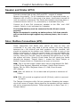
SECTION 2
INSTALLATION
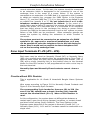
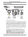
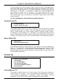
ICs
v
U4 - System configuration Nonvolatile Memory (NVM). This is where all
Engineer programming information for a system setup is stored.
v
U1 - Program IC. This IC contains the ‘firmware’ release for all of
Comfort’s embedded behaviour. This can be replaced for firmware
updates.
v
U7 - Voice IC. Comfort’s voice menu and messages etc. are stored here.
It may be reprogrammed onboard for other vocabularies such as ‘Office’
using a Voice Programmer Board (VPM01) inserted into J11.
Part No: 24LC32A for 8 - 24 zone and 24LC65A for 32 - 64 zone
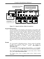
Connections
v
MJ1 - TEL-IN. Connection to Public Switched Telephone Network..
v
MJ2 - TEL-OUT. Connection to House phones.
v
MJ3 - Connection to X10 /TW7223(Europe) ior TW523(US) Interface.
v
JP1 - 15 VAC Transformer Input connection.
v
JP2 12V Battery Connection for Sealed Lead-Acid Rechargeable Battery.
v
JP3 - JP6, Zones 1-8 input connections. Circuits are DEOL, SEOL or Non
EOL.
v
JP7 - 12V Auxiliary and Switched Supply (3 position terminal block).
v
JP8 - RS485 KA/KB (2 position terminal block).
v
JP9 - 12V Siren Connection for 12 Volt sirens, SRN terminal is the
trigger, SRN+ is 12V positive hold-off. 0V may be taken from GND at
J4.
v
JP10 - Speaker and Strobe Connection for Speaker and 12V Strobe
Light.
v
JP15 - RS485 Connection to PC and BUS interfaces (Pin 1 - 4 =
12V,0V,KA,KB).
v
J2 - Header for Program Transfer Board connection
v
J4 - Connection to Panel and Bell box Tamper Switch. Short terminal
block with wire-link if tamper Input is not used.
v
J5 - LEM Connection Point for ribbon cable.
v
J6 - Mains Power On LED header. (no resistor required, it is on the PCB)
v
J11 - 9 way header for voice Programmer Board
v
J13 - For Australian use only
v
J9, J14 - Headers for connection to Ringer Board J1 and J2.
v
J15 - 4 way header for RS485 Upload/Download and 12v supply.
v
J23 - Test connector (4 way header)
21
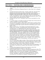
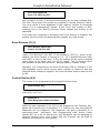
Comfort CPU
22
12-Volt
OUTPUTS
1- 8
SYSTEM
CLOCK
ZONES
1- 8
MJ3
X-10
RS485
KA - KB
DATALINE
J14
TEL. OUT
TEL. IN
Relay Module
(RLY01)
4 x 12V
LEM (LEM01)
9 - 16 Zones
9 - 16 Outputs
Door
Stations
1-3
Homepilot.com
TV Web Access
RedCARE &
DualCom
Alarm
Signalling
Output Control
Control
Output
Away, Day
Night, Holiday
Security Modes
Temperature
Rain / Moisture
Light Level
Movement
Contacts
Vibration
Fire
Gas
TX
Detection Devices
Devices
Detection
Leopard
Touchscreens
Comfort Web
InterfACE
PC Software
Honeywell
Smartfit HVAC
PC
running
CS-Xpress
UCM RS232
Modules 1- 8
RX
Remote Expansion
Panels (SEP) 1-3
17 - 64 Zones & Outputs
Keypads/
Intercoms
1-8
Ringer
RGR01
House
Phones
(Max REN=4)
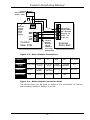
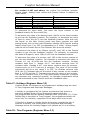
Security&&Control
Control
Security
Sockets
11 9 7
UNIT
L
15
11
13
1
1
3
5
9 7
C
E
I G
A
2
Switch
Module
N
1
auto
0
IR Audio Eqt. Control
External Appliances
Heating, Motors
Lighting Circuits
External Lighting
12
Mains
230 Relay
LD10
AD10
Ceiling / Wall Lights
Dishwashers
Tumble Dryer
AW10
Washing Machines
LW10
Air Conditioner
Radio, HI-FI, TV
Vacuum Cleaner,
Sockets, Sprinklers,
De-humidifyer
Table Lights
IR TV Control
IR Video Control
Door Lock- Release
Shutter Control
InfraRed LED's
located near
equipment
Gate Control
LM12
AM12
Curtain Open / Close
DIN Rail
L
O
M
K
X-10 POWERHOUSE
Video Switching
Camera Switching
Schedulingof
ofResponses
Responses
Scheduling
G
HOUSE
Wall Mount
Time Programs
Programs 11- 16
16
Time
Movement
LAMP
MODULE
X-10 POWERHOUSE
O A C
15 1 3
E 13
5
K I
M
X-10Appliance
ApplianceControl
Control
X-10
Ring Main
Main
Ring
Panic
Function Switching
Radio Devices
TW7223
X-10
Interface
220-240
VAC
Filter / Block
FD10
Neighbouring
Properties
HomeControl
Control
Home
Comfort
Comfort
Concept
Concept
Schematic
Schematic
Reminder
Reminder
Messages
Messages
Doorphone
Remote Control
Pager Reporting
Answer Machine
Messages
Alarm Conditions
Message forwarding
Reminder Message
Alarm Clock
Abnormal Opening
Latch Key Kid
External Telephones
Cellphones
Pagers
Central Station
Communication
Communication
Comfort Installation Manual
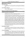
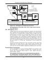
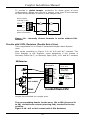
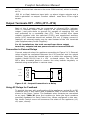
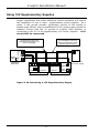
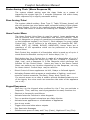
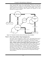
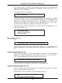
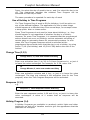
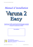
Schematic Block Diagram - Comfort System
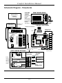
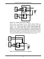
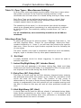
Comfort Installation Manual
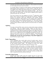
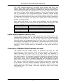
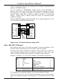
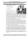
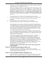
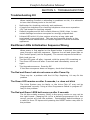
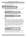
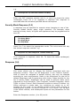
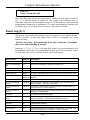
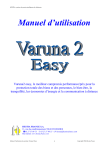
Schematic Diagram - Peripherals
REV 'E' PCB
RELAY BOARD (RLY01)
VOLT-FREE
OUTPUTS
Use to control:
Curtains,
Lights,
Gates,CCTV,
Lock-release,
RedCARE and
Paknet
Transmitter
RedCARE,
DUALCOM or
Paknet
Transmitter
24-ZONE OPTION
CYTECH TECHNOLOGY RELAY BOARD
OP4
12v
OP3
OP2
12V
NC4 NO4 COM4 NC3 NO3 COM3 NC2 NO2 COM2 NC1 NO1 COM1
Outputs 9 - 16
(-ve applied)
16-ZONE LEM (LEM03)
Inputs 16-24
instead of outputs
OP1
4 x 12V
Inputs
4 x NO/NC Contact Outputs
RS232 PC Interface
RS485 DATA LINE
(KA-KB/0V /12V)
RS232
OP9 12v OP10 OP11 12v OP12 OP13 12v OP14 OP15 12v OP16
To Comfort CPU
8-IN/8-OUT LEM MODULE
JZ9
16-ZONE OPTION
(LEM01)
To MAIN CPU - J5
8 IOE CYTECH
LEM
COM 12v
JZ10
JZ11
JZ12
JZ13
JZ14
JZ15
3 2 1
UCM2
KB KA COM 12V
Z9
COM
+
JP2
P1
U6
Z10
RS485
J2
Z11
UCM01
RS232
COM
Z12
+
JP2A
U5
UCM3
KB KA COM 12V
UCM4
SW1
D10
Z13
D12
D11
COM
COPY
Z14
Z15
U2
D9
SW6
U1
SW3
DOWNLOAD
UCM 4.XX
SW7
1
2
3
SW4
TEST
COPY
Z16
UCM6
SW5
COM
SW6
MASTER
UCM5
UPLOAD
UCM7
RDY BUSY BUSY2 ERR
COMPARE
U3
STATUS LEDS
JZ16
UCM8
SEP02
SEP02
SEP02
Programmable Detection
Circuits 9 - 16
Slave Expansion Panels 17- 64 zones
ZONE JUMPER SETTINGS
Circuit
2K7
3 panels (max)
Zone Input
Terminals
4K7
Z4 COM Z3
Tamper
Zones
may be
normally
open or
normally
closed.
Circuit
Z2 COM Z1
4K7
Circuit
Tamper
JZ4
3 2 1
JZ3
3 2 1
JZ2
Double
EOL
4K7 = Yellow,
Violet, Red
2K7 = Red,
Violet, Red
Non-EOL
3 2 1
Single-EOL
23
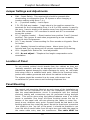
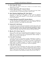
Comfort Installation Manual
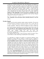
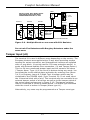
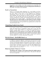
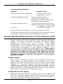
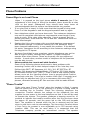
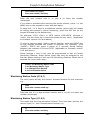
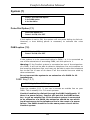
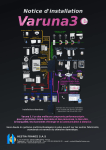
PCB Layout
Outputs Driver
REV 'E' PCB
NOTE
A Master Socket MUST
be used on TEL-OUT to
ensure that all internal
phones will ring
MAIN CPU
REV E
OP 8
12v
U3
OP 7
OP 6
+
RED
STEADY
OP 2
U1
SPK-
STR SRN -
JP10
JP8
Program
JP9
SRN +
RS485
Comms
VR3
U5
KB
RS485
COM
COM
12V / 0V Power lines to
be doubled to reduce
cable resistance.
JZ7
JZ6
JZ5
JZ4
JZ3
JZ2
Z6
COM
Z5
Z4
COM
Z3
Z2
COM
TR
Z1
Case Tamper
JZ1
Screen
connected
to earth at
CPU only
MJ3
X-10
RJ11
VR1
J5
JP15
MIC
Power
LED
+
JP1
U7
0V
JP2
J4
12V Data V-Mic
Important
Each Keypad and Door
Station Cable MUST be run
separately from the panel.
24
X-10 POWERHOUSE
VOICE
(Do not adjust)
Volume (VR3) for
advisory tones and
sirens on, keypad and
Door Station spkrs.
Siren 0v hold-off
and tamper return
Door Station
Intercoms
J14
LEM
VR2
Extension Sockets.
MJ2
SW1
3 2 1
Voice Prog.
3 2 1
Z7
Programmable
Detection
Circuits 1 - 8
A=5
B=2
C = 3 ringer
Master Socket
5 23
CYTECH TECHNOLOGY
Z8
J11
JZ8
12V
Reset
J10
24LC65A
(NVM)
12V 0V KA KB
S12 V
Aux 12 V /
Det. Reset
U4
J15
KA
Keypad
J9
Ringer
12v
+ 12V
Tel.
Out
ALARM TROUBLE
STATUS LEDS
OP 3
OP 1
12V Data V-Mic
GREEN
ARMED HOME
J8 FLASHING
12v
Speaker/
Strobe
Siren
(Advisory Tones
not Voice)
Line OUT
2
OP 5
IR LED
Master Socket
5
RELAYS
OP 4
6K8 - 100 ohm
BT Line IN
5
2
MJ1
PHONE
12v
Programmable
Outputs 1 - 5
(-ve applied)
Tel.
In
JP1 to J14
RINGER
MODULE
JP2
to J9
TW7223
X-10 Interface
Feeds control signals
onto 230VAC Ring
Main to switch
appliances and/or
lights.
15 VAC
12V Battery
(Sealed Lead-Acid)
Ringer module
should be
connected if the
doorbell and
reminder
messages are
required to ring
the phones.
Comfort Installation Manual
Jumper Settings and Adjustments
v
SW1 - Reset Switch. This reset switch should be pressed after
downloading a configuration from CS-Xpress or after changing a
Location setting using Menu 7,4,1.
v
J1 - (2 position header) - Leave Open
v
J Z1 -JZ8 3x8 way header - Insert shunt in the position nearest the
terminals for the corresponding Zone 1 to 8 if no EOL resistor is used for
the zone. Insert a shunt in the position away from the terminal block if
Double EOL resistors: 2K7 connected in series and 4K7 is connected
across the contact.
v
J10 (3 position header) - Shunt inserted over position 2 and 3 (normal
position). This jumper is used when programming a new vocabulary
using the Voice Programmer.
v
J19 - 2 way header. Volume setting for Siren sounds on Keypads. Shunt
for louder.
v
VR3 - Speaker Volume for advisory tones. Alarm tones (e.g. for
Intruder and Fire) are always at full volume regardless of this setting.
v
VR1 - Keypad/Door Station Mic level adjustment
v
VR2 - Do not adjust! - Telephone line length compensation-echo
cancellation
Location of Panel
Do not remove printed circuit boards from the cabinet as they are
‘statically sensitive’ and may be damaged with incorrect handling. Take
precautions against damage by static discharge by using an anti static
wrist strap tied to a suitable earth point. Remove the knockout holes,
protect with rubber grommets and mount the cabinet to the wall.
The system should be mounted in a dry area, with access to an
un-switched AC power source and incoming telephone line.
Panel Mounting
The control unit should be fitted at an early stage of the installation so
that runs can be connected in as they are completed, thus verifying
that the zone/cable/detector circuit is operational and the relevant
electrical testing and connections may be performed during daylight
hours. This can be done using the backup batteries even if no mains
power is available. Run large 40-60mm trunking across the top or
bottom of the panel with cut-outs allowing the cables to enter the
panel at any mublicon entry point. Screens should be tied back to the
earthing posts as they enter the panel. Mount the fused spur connection
box ideally to the top left of the panel, it should be possible to run
1mm flat twin & earth cable from the spur box and under the panel to
the mains cable entry near the transformer. The cable MUST be
25
Comfort Installation Manual
firmly anchored using the cable tie and adhesive pad provided
next to the cable entry hole. Do not run mains cable through the
same entry hole as low voltage circuit cables. Sharp metal entry holes
should be protected with edge strip or rubber grommets. Always
connect the earth from the mains cable to the panels mains earthing
point terminal block, use earth sleeving to protect the exposed earth
wire. Try to run cables neatly through the centre of the panel casing in
a loom, with branches coming from the loom as each zone cable is
connected to the terminals.
Clearly label all cables with their zone number and detector
location.
Mains Supply - 230 VAC
The transformer should be connected to an un-switched fused spur
power supply outlet. Where regulations require, connect a 16 AWG
green-jacketed solid conductor ground wire from the earth terminal on
the studs provided on the enclosure to a metal pipe, grounding rod or
other established earth ground for protection against lightning-induced
surge.
(
(
For UK Installations: The mains installation should be carried
out by a qualified electrician in accordance with Electrical
Wiring Regulations (BS 7671) and the current IEE regulations.
As this is a permanently connected equipment, the fixed wiring
must have a readily accessible disconnect device, e.g.
Un-switched fused spur.
Ensure that continuous current supplied from the AUX
terminals and outputs is less than 850 mA.
Ensure the supplied green earth bonding lead is connected to the front
cover using the spade prior to replacing the panel lid.
Back-Up Battery Supply - 7Ah (JP2)
Connect a 12V 7 AH sealed lead-acid battery to the BATT (JP2)
terminals. The Zone Expansion boards requires less than 35 mA.
Connect the positive terminal of the battery to the + terminal of JP2
and the negative terminal of the battery to the - terminal of JP2. The
battery provides standby power to the system in the event of power
failure and supplies additional current when required, e.g. to drive the
siren during an alarm. The battery current is limited to 2.5A by a
resettable fuse (F1).
(
The system may not operate correctly without a backup
battery.
Back-Up Battery Calculation.
Standards require that alarm systems must be designed and installed
with adequate battery back-up capacity to run the system for a
minimum number of hours upon a loss of mains power. To do this, first
establish the system ‘Quiescent’ Current (QC). This value in Amps
26
Comfort Installation Manual
should be multiplied by the minimum time duration that is required
under the relevant standards. The Amp/hour battery size should be of a
higher capacity than the result of the calculation. It is always advisable
to install the highest capacity battery which can physically fit into the
enclosure (7A/hr).
E.g.:
QC = 0.650 A
(650 mA)
8 hours required stand by
QC x 8 = Battery Size A/hr (Min)
0.650 x 8 = 5.2 Amp-hour,
Amp-Hour
Next available Battery size is 6
Factory Restart
Comfort does not have a factory restart setting. The configuration is
stored within U4 Non-volatile memory (NVM), so either this can be
replaced with a formatted U4 with default values or you can use
CS-Xpress to overwrite the current configuration with a default
template. You can write a default NVM using the UCM01 module’s copy
socket by inserting a master default NVM placing a spare 24LC65 IC in
the copy socket and pressing ‘Copy’ on the UCM01 local button. This
takes around 12 seconds to write.
27
Comfort Installation Manual
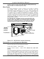
Cable Routing / Requirements
The minimum cable type to be used for detection devices, sounders and
Keypad and Door Station connections should be 6-core alarm cable
(7/0.2mm). This has a resistance of 8 ohms per 100 metres. Screened
cables are preferred for Keypads, Door Stations and each one run from
the panel separately. Use spare cores to double-up the 12V power
supply cables to the each control station to reduce circuit resistance and
further improve current performance.
Ensure that all RS485 communication lines and detection circuit cables
are kept away from mains supply cables. Comfort’s enclosure is
designed with the Engineer in mind.
Large plastic inserts called
‘mublicons’ allow large gauge trunking to be brought to the panel in
four locations. Extensive rear access is also possible using the many
entry holes in the backplate. Various mounting positions are provided
for LEM’s, Relay Boards and Ringer Board.
Screened cable is essential where system wiring is to be run adjacent to
cables that produce RFI or are switching high-current loads. When using
screened cable connect the screen to earth at the Comfort Panel end
ONLY using the supplied anchor posts shown below. At the keypad end,
just cut the screen short and insulate.
Wall Fixing
Point
Cable Entries
Panel
Tamper
Switch
Transformer
FUSE
TW7223
Interface
position
N
Spade connector
for earth to front
cover
L
Wall Fixing
Point
Main CPU
PCB
Usual LEM
Position
Relay Board
Positions
Screened
anchor posts
Alternative
LEM Position
Alternative
Ringer Position
Wall Fixing
Point
Usual Ringer
Position
Standby battery
7.0 Ah
Cable Entry
Cable Entry
28
Wall Fixing
Point
Comfort Installation Manual
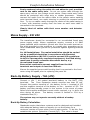
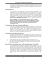
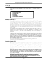
Keypad and Door Stations
Loudspeaker
Loudspeaker
Volume
Control
VR1A
Volume
Control
SW4
Tamper
C B A
Bk light
On Nor
SW4
Tamper
C B A
SW1
ID Selectors
SW1
ID Selectors
JP4
1
2
3
1
2
3
Key Tone
(Remove for soft)
JP6
JP8
PC01-007C
Keypad
JP5
Microphone
KP
DP
JP5
KP
DP
JP7 - TAMP
(Remove to enable)
JP7 - TAMP
(Remove to enable)
Microphone
PC01-007C
Door Station
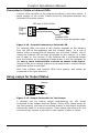
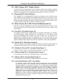
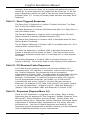
Figure 2.1 - Keypad and Door Station Settings
Open the Keypad housing by gently pushing a screwdriver into the two
slots at the front bottom one at a time while simultaneously prizing the
front cover from the base until the catch releases. Do Not insert the
screwdriver in too far or twist the front cover away from the
base as this will break the catches. Separate the front and back
housings by pulling the top housing firmly and squarely away at the
bottom edge.
Mount the back housing on the wall using the screws supplied. Connect
the 6 wires from the terminal blocks on the Keypad to the Comfort PCB
according to the connection diagram above. The Comfort Panel should
be switched off during the Keypad installation.
The total resistance of each 12V and ground wire run should be less
than 5 ohms. If necessary, use an extra pair of wires for 12V and 0V
ground.
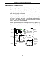
If more than one Keypad/Door Station is used, connect their
12V and ground wires directly back to the Comfort control
panel. Do not connect in series.
29
Comfort Installation Manual
IMPORTANT
Ensure that each Keypad's 12V/COM wires
are connected directly to the Control Panel
and not in series. It is recommended that
8-core cable is used to double-up spare
cores with 12V Aux supply feeds to reduce
voltage drop.
Screen connected to earth at CPU only.
Zone 'COM' terminals are at 0V and may
be for screen earth connection.
MIC
VOICE
+12V
+12V
12V
COM
S12V
VOICE MIC
RS485
0V
COM/0V
KA
KB
KA
KB
COMFORT
MAIN PCB
VC M IC
KA KB 12V COM
C B A
Important Comms Locations
No. of Door Stations
1674
No.of Keypads/Intercoms 1675
Ensure JP5 is correctly inserted !
VC M IC
KA KB 12V COM
C B A
VC M IC
KA KB 12V COM
VC M IC
Keypad 1
Keypad 2
Keypad 3
I/D = 1
I/D = 2
I/D = 3
KA KB 12V COM
C B A
C B A
Door
Station 1
I/D = 1
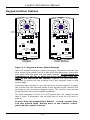
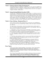
Figure 2.2 - Keypad and Door Station Connections
Keypad PCB Versions
The PCB version of the keypad is silk-screened on the bottom right
corner of the board. PC01-007B does not support the Infrared receiver
function which is found within the KP02, while PC01-007C (released in
January 2001) does support Infrared receiver function, with the
appropriate components soldered in, as well as a shunt to permanently
turn on the backlight
The differences in the shunt settings are
described below. Keypads (KP01) after January 2001 will also use this
version PCB and may be converted for use as Infrared receivers by
soldering 2 components, an IR Led (3 legs) and a capacitor. This IR led
may be mounted up to 100m away from the keypad PCB, in which case
the cable running to the LED will require soldering on the KP01 or KP02
PCB.
Shunts
JP4: 3 pin header for Backlight selection. “Normal” position for backlight
on when key is pressed, Entry alert or Alarm. “On” position for
Backlight permanently on. Default - “Normal”. This applies to
PC01-007C only
JP5: Keypad/Door Station selection: Shunt positions 1 - 2. for Keypad,
2 - 3 for Door Station. For PC01-007C, JP5 is horizontally oriented
JP6: Keypad key Beep volume. Short for louder beep volume. Default
Open (soft). Not on Door Station PCB
JP7: Tamper Shunt. Short to disable tamper switch. Default shorted
(disabled)
30
Comfort Installation Manual
JP8: Disable Doorbell button. When shunt is removed, door station
button is disabled. The shunt is removed when the Door Station is used
as a keypad (JP5 to keypad position) for announcement. This applies
to PC07-007C only.
SW1: ID selection
Setting the Microphone Levels
On the Comfort CPU, VR1 sets the MIC recording and listening level for
the Microphone. Adjust this trimmer when in two way Voice Station
Mode between a telephone or mobile phone and keypad or Doorphone
rather than between two keypads to so that any feedback may be
adjusted out. This is normally set at about 50%. In practice the volume
of the internal speaker volume within the doorphone need only be
slightly off zero. While in Doorphone menu between a telephone and a
Doorphone (kept at least 4 metres apart), turn the pot fully clockwise
and then slowly turn it anti-clockwise at the same time being aware of
the start of feedback. The correct level would be about 2-3mm off hard
right.
31
Comfort Installation Manual
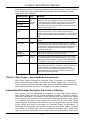
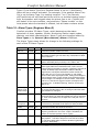
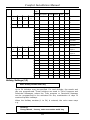
Keypad / DoorStation ID Selection:
Set the headers SW1 according to the ID of the Keypad according to
the table
ID
SW1- C
SW1 - B
SW1 - A
1
2
3
4
5
6
7
8
Short
Short
Short
Short
Open
Open
Open
Open
Short
Short
Open
Open
Short
Short
Open
Open
Short
Open
Short
Open
Short
Open
Short
Open
If a Door Station is installed, then a maximum of 3 Keypads may be
installed using the Comfort PSU. The ringer module RGR02 may also be
fitted. This rings the phone for 30 seconds whenever the doorbell is
presssed during ‘occupied’ modes. Up to 8 Keypads may be installed in
a system and including a maximum of 3 Door Stations (After version
4.100). If additional Keypads are required (4-8), a supplementary
12VDC power supply rated at 1A DC with battery back-up must be
installed. The negative (com) of the Comfort CPU auxiliary 12V output
should be connected to the negative 0V of the PSU as a reference.
Keypad ID’s must be numbered consecutively, for example, if there are
2 Keypads they must be set to ID’s 1 and 2.
After termination of the wires and ID selection, close the Keypad by
hooking the front housing to the back housing along the top edge and
pushing the bottom of the front housing into the back housing.
Switch on power to the Comfort Panel. A short beep should be heard on
the Keypad followed by "Security Off". The appropriate indicator LEDs
should light up. Now, program the number of Keypads and Door
Stations in the next section.
Door Station as Intercom
The Door Station can be used as an intercom within the premises, by
making it appear as a Keypad. Set JP5 so that the Door Station is a
Keypad. Set the ID switches in SW1 to select the next available address
for a Keypad. Program Location 1675 to correspond to the number of
Keypads in the system. Reset the Comfort panel. Pressing the Doorbell
button will initiate the Intercom mode just like pressing the F + 8
function key. The Doorbell button also switches communications to talk
mode when communications is established. However, this intercom
cannot terminate the Intercom Mode, as there is no F key. Intercom
mode can be terminated by the other Keypad or can be left to ‘time
out’. For more natural conversation use the telephone to answer the
Door Station or Intercoms and to listen to Keypads use Menu 5.
(
If Ringer Module RGR02 is fitted with Door Station, ensure
that Location 40 (Table 35) is set to a value of ‘4’ if RGR01 is
fitted then Location 40 can be set to ‘0’.
32
Comfort Installation Manual
Speaker and Strobe (JP10)
Connect a strobe light to the 12VF and STR - outputs if needed.
Observe the polarity. For UL Installations use a UL approved strobe, eg
Wheelock LS1-12-VFR. In the event of an alarm, the strobe is turned on
until the system is disarmed. The Strobe and speaker terminals have a
combined current limit of 1 A, protected by a resettable fuse (F3)
Connect an 8 ohm 5W (minimum) speaker to the SPK- and 12VF
outputs. Polarity is not important for a speaker.
(
(
The backup battery must be connected for the Siren to work
properly.
When the system is running on battery alone, full siren sounds
will not sound through keypads to preserve power, this is not a
fault .
Siren / Bellbox Connections (JP9)
Some ‘supervised’ bell boxes may ‘sound’ as soon as they are
connected. If so, they may need a pull-up resistor (1K-ohm) placing
between the +12V hold-off and their negative ‘trigger’ terminal, this
should be inserted at the bellbox end. Should you wish to work on the
bellbox connections or open the control panel, you can immobilise the
system from causing a tamper alarm by entering Engineer Test Mode
via Eng. Menu 8,6,1 for ON. Upon de-selecting this option 8,6,0 for Off,
the system will enter ‘Security Check Mode’ and will report any faults
through the keypad. ‘Tamper Alarm 1’ means the Panel Tamper or
Bellbox Tamper switch or Connections are open or incorrect.
SRN- This is the bell trigger output which can be programmed for SAB
or SCB (Siren Reverse) operation as follows: Select Siren Reverse
Option ‘ON’ for SCB in Engineer Menu 4,3. SAB, Siren Reverse
OFF=Default.
SAB: SRN- will switch to 0V on alarm and will provide a maximum of
700mA.
SCB: SRN- will provide a negative hold off (500mA), which is removed
on alarm.
The Tamper Connections offer 24 hour protection. Breaking the tamper
circuit will cause a Tamper Alarm signal on the speaker and can cause a
dial out to programmed phones. These settings are in Alarm Type 11 (
Tamper Alarm).
33
Comfort Installation Manual
Panel Tamper
Switch - (N.C.)
Remove
Link to
enable
panel
casetamper
0V Hold Off
Tamper Return.
12V + Hold Off
SRN Trig - ve
Strobe - ve
Strobe +ve
0V - TR
SRN+
SRNSTR12VF
SPK-
1K-Ohm
Pull-Up
Resistor
may be
needed if
siren rings
permanently
Comfort
Main PCB
External
Siren/ Bell
Figure 2.3 - Siren /Bellbox Connections
COMFORT
CEQURA
(CQR)
GARDTEC
VENTCROFT
TR
12VF
A/T RET SIG HOLD OFF
+12Vdc
TMP RET
RTN
0V
HOLD OFF
-12Vdc
SRN-
STR-
SIREN
STROBE
TRIGGER TRIGGER
12V SUPP+ 12V SUPP- BELL SW- STROBESTROBE+ F TMP FEED
HOLD OFF+ HOLD OFF-
TRG
NOT USED
SET
BELL SW+
STB
Figure 2.4 - Bellbox Model Connection Chart
The above chart can be used to assist in the connection of Comfort
some leading makes of bellbox in the UK.
34
Comfort Installation Manual
Telephone Connections
Single Line Telephone Connection
Comfort must be connected in series between the incoming telephone
line and the house phones using solid core telecom cable and not
stranded alarm cable. Use the proper jointing IDC (Krone) tool for
making connections rather than a screwdriver. Connect the incoming
telephone line to the TEL IN Terminal Block. Connect the telephone
wires going to the house phone(s) to the TEL OUT Terminal Block. The
system will work with any tone-dialling telephone. For retrofit
applications where the panel is sited away from the incoming telephone
line, a single cable (6 or 8 core solid) can be used to divert the
telephone line through the Comfort panel using only 5-cores (see fig
2.5). A ringer module (RGR01 or 02) should be used if the doorbell and
reminder messages are required to ring the telephone.
Telephones, facsimile machines and other telecommunications
equipment may be connected to the Telephone OUT socket.
(
Do not connect any other equipment between the incoming
telephone line and the control panel. Also, do not connect any
other telephone equipment including fax machines and PABX in
parallel with the control panel. Violating the above conditions
may prevent the control panel from seizing the telephone line
to dial out during an alarm condition. If telephone equipment
are connected in parallel with the system, a Phone Trouble
condition will be generated if the parallel equipment is used.
MJ1
TEL
IN
A=5
B=2
C = 3 ringer
2
5
Comfort
CPU
TEL
OUT
BT Line IN
2
MJ2
5
6
5
1
Master Socket
NT5
3
2
4
3
5
Comfort
Master Socket
2
325
NOTE
A Master Socket MUST be
used on TEL-OUT to ensure
that internal phones ring
Secondary
Sockets
House Extensions
4 REN Max.
Figure 2.5: UK Retrofit Telephone Connection example
35
Comfort Installation Manual
Comfort CPU
MJ1
BT Line IN
2
TEL
IN
2
5
5
make joint
Master Socket
NT5
A=5
B=2
C = 3 ringer
3
House Extensions 4 REN
recommended Maximum
by Telephone companies.
3
5
TEL
OUT
MJ2
2
3
5
2
3
5
2
Master or secondary
socket. see below
Secondary
Sockets
With Ringer Module
Without Ringer Module
Use a master socket on Tel Out if the ringer
module is used for doorbell and reminder
messages. The master socket creates a ring
connection (3) from the line (2,5).
Use a secondary socket if ringer module is
not used and ensure that the ringer wire 3 is
carried through to all house phones.
Figure 2.6 - UK Single Line Telephone Connection
(
UK Installations should take note of the ringer module options
described above.
UK - BT Highway (ISDN)
Comfort cannot be used across digital lines, however, the service such
as BT Highway has two analogue sockets available on the Junction Box.
Thie main line is provided with a Master Socket, connect from this
socket directly to Comfort’s TEL IN socket and Comfort’s TEL out should
be connected to a new master socket which will feed the house
extension sockets. This is important to enable the phones to ring from
both the doorphone and an external phone call. Additionally, if you find
problems with dialling out through Comfort using local phones (ie. You
hear a BT recorded message) try reversing the polarity of the incoming
line into Comfort, ie, reverse the connnections A and B leading into
Comfort.
Remember that the analogue port may not function at times when both
digital lines are being used for a fast internet 128k connection and
could result in a ‘phone trouble condition’ being generated on Comfort.
This (Line Cut) may de disabled if absolutely necessary (See next item).
Parallel Phone Connections
If it is not possible to run the incoming telephone line directly to the
TEL IN terminals, it is possible to connect TEL In parallel with other
phones. See Worksheet Table 35 and 17 under “Ignore Line Cut or
phone trouble” setting.
(
This method of connection is not recommended especially for
UL installations or monitored systems, and is only applicable to
Home Automation installations where security is not a concern.
36
Comfort Installation Manual
UK - ISDN Digital Phone Systems (ISDN 2e)
Comfort can connect to Digital Phones systems, but only onto an
analogue extension or terminal adaptor. The ringer module is not
required for such installations as the system doorphone operation has
to be set-up to initiate a dial-out in all modes. This is achieved using
responses. Full details are provided in the Applications Manual or on the
Technical Website www.comfort.org.uk/technical/indexapp.html.
Connection to Keyphone and PABX systems
A key telephone system may be to the TEL OUT socket. To access the
system with a key telephone, press the button which selects the
incoming line to which the system is connected, and press *, sign-in
code and # in the usual way. The system cannot be connected as an
extension of a key telephone system. Remote telephone access can be
achieved by dialling into the exchange line to which the system is
connected.
A PABX may be connected to the TEL OUT socket. A telephone may be
connected in parallel to the PABX, to be used for local system access.
Remote telephone access can be achieved by dialling into the exchange
line to which the system is connected. See Figure 2.7 for connection
(
With this method of connection, the extension phone will not
be able to access the system if the CO line for Comfort is in use.
Also, for remote access, the user must dial the precise number
and not the hunting line to ensure that Comfort can receive the
call.
MJ1
TEL IN
MJ2
TEL OUT
CO 1
Incoming
Telephone
Line
PABX
or
Key Phone
System
Fax
Control Phone
Figure 2.7 - Connection before PABX/Keyphone System
Connection to extension of PABX (Not for UL Installations)
It is also possible to connect the system as an (analogue) extension of
a PABX, for non-monitored systems. A normal telephone may be
connected to the TEL OUT socket for system access and for use as a
37
Comfort Installation Manual
normal extension phone. In this case, the system should be connected
to an extension which is designated to be connected to one of the
exchange lines in the event of a power failure. If the system is
connected as an extension of a PABX and it is required to dial a number
to obtain an outside line, program the PABX Option in the Engineer
Menu (7,2), and the PABX Key (7,2,1) to the prefix to be dialled to get
an outside line (usually 9 or 0). Do not include the 9 or 0 in the
telephone numbers programmed for dialout. In the event of a
power failure and a dialout is required, the system will dial the numbers
without the prefix, as it assumes that it is connected to an extension
that has direct access to the exchange line during a power failure.
Connect the PABX to the same electrical circuit as the system so power
failure of the PABX can be monitored. Other extension phones can
access the system by dialling the extension to which Comfort is
connected.
(
The system must not be connected as an extension of a PABX
system for UL- approved or monitored installations, as it may
not be possible to seize the telephone line to dial out during an
alarm. Also it would not be possible to detect telephone line
cut on the incoming exchange lines.
Zone Input Terminals Z1- Z8 (JP3 - JP6)
Each zone may be wired as Normally Closed (NC) or Normally Open
(NO). Any unused zones should either be programmed as Zone Type 0
with the zone inputs left open and corresponding zone header (JZ1 to
JZ8) with a shunt (shorting link) in the position close to the terminal
blocks for Non EOL resistor or left programmed but with a wire loop in
the zone terminal.
(
Normally Open and Normally Closed contacts cannot share a
zone.
Circuits without EOL Resistor
This is applicable for UL Grade B Household Burglar Alarm Systems
units
Wire zones according to Figure 2.8 for Normally Closed Contacts and
Figure 2.9 for Normally Open Contacts.
The corresponding 3-pin header for the zone, JZ1 to JZ8 (for
zone Z1 to Z8) should have a shunt (shorting link) inserted
nearest the terminal block (2 to 3) when no EOL Resistor is
used .
In this configuration, the system does not differentiate between a
contact open, open circuit wiring (tamper) condition, or contact closed
and short-circuit wiring (fault) condition. The Zone Settings in the
Engineer menu determine if the contact is Normally Closed (N.C.) or
Normally Open (N.O.). N.O. and N.C contacts cannot be connected on a
single zone.
38
Comfort Installation Manual
To provide a ‘global tamper’ protection for these types of zone
configurations, assign one zone as a ‘tamper’ zone type 20 and connect
all zone wiring tampers in series to this tamper zone.
Zones must be
normally closed.
JZ1-8
3 2 1
Zone
Alarm
COM
Alarm
Zone
Shunt on pins 1 & 2.
(Near to terminals)
Tamper
Tamper
Figure 2.8 - Normally Closed Contacts in series without EOL
Resistor
Circuits with 2 EOL Resistors (Double End of Line)
This is applicable for UL Grade A Household Burglar Alarm System
units.
Wire zones according to Figure 2.10 for N.O and N.C contacts. The
Zone Settings in the Engineer menu determine if the contact is
Normally Closed (N.C.) or Normally Open (N.O). N.O. and N.C contacts
PIR Detector
Zone Input
Terminals
-
2K7 = Red,
S12V
Violet, Red
0V
12V
Double
JZ8
EOL
Z8
Position
3
2
1
COM
JZ7
Z7
PWR
+
4K7
4K7 = Yellow,
Violet, Red
ALM
(N.C. or N.O.)
2K7
3 2 1
Comfort Main CPU
TAMP
cannot be connected on a single zone.
(
The corresponding header for the zone, JZ1 to JZ8 (for zone Z1
to Z8) should have a shunt (shorting link) inserted in the top
position.
Figure 2.10 - N.C or N.O contact with 2 EOL Resistors
39
Comfort Installation Manual
The 2 EOL resistors should be connected at the contact and not at the
control panel. With 2 EOL resistors connected in this way, the system is
able to distinguish open and closed contacts from open circuit and short
circuit wiring providing full supervision of the zone contacts and cables.
Any short or open circuit fault will trigger a Zone Trouble Alarm which
can be reported to the programmed phone numbers. Where double
end-of-line resistors are used, the following circuit resistances should
be measured and verified on the zone wiring PRIOR to their connection
into the zone terminals. Use them as a guide when commissioning a
system or tracing a fault.
Also check that there is no short circuit between the 12V auxiliary
supplies and zone circuit wiring and the power cables connected to the
auxiliary supplies do not contain any shorts between 0v and 12V.
Status
Zone Resistance (Ohms)
Closed /Healthy
2K7
Open / Active
7K4
Tamper / Fault
Open circuit (infinity)
Shorted / Fault
zero
4-wire Smoke Detectors (End Of Line)
Smoke Detectors are usually connected as Normally Closed (N.C). The
corresponding Header JZ1 to JZ8 should have a shunt (shorting link)
inserted into the position away from the terminals. Smoke and Heat
Detector zones are programmed as Fire Zone Type 23. A Pulsed On/Off
siren pattern indicating Fire Evacuation is produced when this zone type
is activated (by default). If the zone wiring is cut or open-circuit or
shorted, a Zone Trouble alarm is generated for fire zones using EOL
resistors.
Connection of Multiple Shock Detectors to a zone
The system has the unique ability to announce the type of
the
activated zone during Security Check (during arming) , alarm history,
alarm tracking, and event log. So if more than one detector is
connected to a zone input, it should ideally be of the same type and in
the same location, for example, magnetic contacts for several windows
in the same room. The following diagram shows shock detectors on the
same zone. Some ‘active’ vibration detectors such as Optex can latch
their LED on following an alarm for identification. To make the most of
this feature, supply the detectors via a normally closed relay connected
to an output. Use the arming response (location 1850) to pulse the
output using a response to reset the detectors during arming by
interrupting their the supply, this may announce their zone briefly
during arming.
40
Comfort Installation Manual
RLY01
OP8
12V
OP7 Output
OP6 Terminals
12V
OP5
RELAY 'PULSE' WILL RESET SHOCK
AND SMOKE DETECTORS USING
ARMING RESPONSE IN LOC 1850
Detector 3
Detector 2
Detector 1
+
+
+
PWR
PWR
-
4K7
CCT
PWR
-
4K7
CCT
LNK
2K7
TAMP
-
4K7
CCT
LNK
TAMP
Zone Input
Terminals
TAMP
Single cable
returns to the
panel zone
4K7 = Yellow,
Violet, Red
2K7 = Red,
S12V
Violet, Red
0V
12V
Double
JZ8
EOL
Z8
COM 3 2 1 Position
JZ7
Z7
3 2 1
Comfort Main CPU
May need to use a terminal block to joint the zone wire between detectors
Figure 2.9 - Multiple Shock on one zone with EOL Resistors
(
Do not mix Fire Detectors with Burglary Detectors under the
same zone.
Tamper Input (J4)
The terminal J4 is used in different ways depending on the country. The
European Versions are supplied with a 3-way block providing a spare
terminal for series connection, and International Versions are supplied
with a 2-way block. J4 can be used for CPU case protection and/or in
series with External Audible Siren connection. (0v and Tamper Return).
This is a 24 hour monitored tamper input and will caused a full alarm
(‘Tamper Alarm’ Type 11) if the circuit is broken during any mode. You
can break the circuit without alarm activation by entering User (Menu
3,4,2) or Engineer (menu 8,2) Walk Test. A tamper switch may be
connected to the TAMPER input (2 pin Terminal J4). If not used, short
the J4 terminal block with a wire. This terminal may be connected to an
external tamper switch of a bell box as well as to the tamper switch of
the control panel enclosure as in Figure 2.12. The tamper switches
may be connected in series as shown below. The Alarm type activated
when the circuit is broken is Tamper (Alarm type 11).
Alternatively, any zone may be programmed as a Tamper zone type.
41
Comfort Installation Manual
2K7 EOL resistor required
for UL installations
J4
Tamper
International Versions
COM
Tamper
Tamper
Remove Link to
enable panel
case- tamper
0V - TR
J4
Tamper
Return.
CPU Tamper
Switch - (N.C.)
0V
European Versions
Figure 2.12 Tamper Input connection
‘Negative Applied’ Detectors
Certain types of detector such as outside PIR’s and photocells provide
an open-collector output as a trigger rather than a relay output. This
type of signal can be connected directly into a zone terminal providing it
is a negative signal in one state and ‘floating’ in the other state. If the
signal goes negative when detecting, use a normally-open zone type
such as Type ‘8’ (normally-open switch). This is suitable for light
sensors or external non-alarming detectors which may be used as
monitors to drive Responses for lighting and CCTV applications.
The negative signal should be applied to non-eol zone where the trigger
wire connects just to one side of the zone, provided the detector has a
12v supply derived from the panel acting as a reference.
If tamper protection is required on the zone, three wires will be
required and the zone jumper should be removed from the header. A
single 2K7 resistor should be fitted in series with two of the wires at the
detector. The detector’s negative trigger should then connect to the
side of the resistor and wire which returns to the zone terminal and
42
Comfort Installation Manual
NOT to the wire that returns to the zone COM terminal, which is already
at 0V .
‘GJD XL or Opal’ detectors have both -ve alarm trigger outputs and a
built-in photocell -ve output. Comfort ‘default ’ uses zone 13 for a light
sensor.
Output Terminals OP1 - OP8 (JP11-JP14)
Each of the 8 outputs may be connected to infrared LEDs, indicator
LEDs or external relays. Each output is an open-collector transistor
output ( and pulls down to ground 0V) capable of supplying 200 mA
and protected by a resettable fuse (F2). Total current from these
outputs together with the switched (S12V) and unswitched auxiliary
power (12V) terminals should not exceed 500 mA. If higher current is
required, an external supply may be used instead of the 12V terminals
(see Supplementary Power Supplies).
(
For UL installations, the total current from Alarm output
terminals, outputs and aux power should not exceed 500 mA
Connection to External Relays
Connect external relays for appliance according to Figure 2.13. External
relays should be connected between the 12V terminal and the output
terminal. They should be located near to or within the enclosure. Relay
module (Model RLY01) has 4 x 12V on-board relays. The CPU and
REP’s have threaded posts to receive the relay boards singularly or
stacked using metal pillars in various sizes.
-
OUTPUT
Appliance Relay
N/O
N/C
12V
OUTPUT
+
COM
Figure 2.13 - Output Connection to a Relay
Using AC Relays for Feedback
To provide the user with confirmation of the appliance’s actual On or Off
condition use a 2 way switch and a feedback relay or current sensor, as
shown in the figure below. The feedback relay contacts are connected
to an input. Table 26 gives the Locations to enter the Input numbers
providing feedback for each Control Key. When configured in this way,
the Home Control menu will announce the state of the appliance (on,
off, open, closed).
43
Comfort Installation Manual
High Voltage Box
OP
L
COM
2 way manual
switch
12V
N/C
OP
N
N/O
Lighting Relay (10A)
Light
Fuse
N/O
IN
N/C
COM
IN
N
COM
Feedback Relay
Figure 2.14 - Output Control with Feedback
Instead of an AC operated relay for feedback status indication, a
current sensor (Model CSM01) can be used, as shown in the next
diagram. The insulated “Live” mains wire goes through the loop of the
current sensor. Do not put both L and N wires through the
sensor.
The current sensor senses the AC current flowing in the
mains wire and gives a closed contact status on its output, which is
connected to one of the zones designated for feedback. Compared to
using a relay, this method has the advantage of not having any contact
with the mains voltage. The sensitivity of the current sensor is 100 mA
RMS. If the appliance being controlled takes less than 100 mA, put two
or more turns of the ‘Mains Live’ wire through the current sensor.
Relay Box
IN
COM
IN
OP
L
COM
Current Sensor
12V
OP
+
2 way manual
switch
N/C
N
N/O
Lighting Relay
(10A)
Light
Figure 2.15 Using Current Sensor for Feedback
44
Comfort Installation Manual
Connection to Visible or Infrared LEDs
Connect infra-red LEDs to the outputs according to the figure below. A
series resistor of 100 ohms 2 Watt should be connected between the
infrared LED and the output.
100 ohm 2 W for IR led
-
Output
12V
Output
+
+
Infrared LEDs
Use 2 or more for greater range
Figure 2.16 - Output Connection to Infrared LED
For Infrared LEDs, the value of this resistor depends on the distance
from the LED to the appliance and the incident angle . As a rule of
thumb, within 4 meters and 15 degrees, use 100 ohms (2 Watt) Aim to
mount the infrared LED as close as possible to the receiver, in a clear
line of sight to the receiver. If the Infrared LED is positioned further
from the receiver or is pointed at a larger angle, it may be necessary to
use two or more infrared LEDs in series as shown in the figure.
Infrared LEDs from a single output may be positioned to control several
appliances within line of sight.
Note that indicator and infrared LEDs have polarity and should be
connected in the right direction.
Using Lamps for Output Status
12V Lamp
12V Lamp
Figure 2.17- Output Connection to Test Lamps
A valuable tool for testing output programming are 12V lamps
connected to the Output terminal Blocks. Unlike LEDs, these lamps do
not have polarity, and can be connected directly to the Output terminals
without the need for a series resistor. These lamps take around 80 mA
current so they impose a real load on the outputs, similar to relays.
45
Comfort Installation Manual
12V Auxiliary Supply Outputs (12V and S12V)
12V and GND supply 12V to devices which require power e.g.
movement detectors. The S12V terminal provides 12V to external
devices which require resetting when activated, e.g. smoke detectors.
The S12V supply is switched off for 5 seconds whenever the system is
disarmed. Total continuous current from these and the Output 12V
terminals should not exceed 1 Amp. These terminals are current limited
by resettable fuses.
Arming Response
There is now an Arming response (Location 1850) which allows shock
detectors to be reset during the exiting procedure instead of at the
point that the system is Disarmed (which can reset the detector before
the culprit has been identified). You can feed such detectors via a relay
which is normally closed and pulse the output feeding the relay using a
pulsed output responses (eg. 130,20,8 = pulse OP8 for 1 second),via
the Arming Response in Location 1850.
False Alarm on Disarming
This may be caused by connecting PIRs or Keypads to the S12V output
instead of the 12V terminals. S12V and 12V share the same terminal
block. S12V is meant for detectors which need to be reset on
disarming, and is switched off for 5 seconds when the system is
disarmed. PIRs programmed as 24 hour zones which have their supply
connected to S12V will activate when disarmed. Also Keypads which are
powered from S12V will report ”Communication Failure”.
(
(
Do not feed PIRs set as 24 hour zones from the S12V supply.
For UL installations, the total current from Alarm output
terminals, outputs and 12v terminals should not exceed 500
mA
46
Comfort Installation Manual
Using 12V Supplementary Supplies
Larger installations that place additional current demands will require
the installation of one or more supplementary power supplies. As a
guide, if the normal standby (quiescent) current of the system is
greater than 850mA, then an additional 12V DC power supply should be
installed. Ensure that the 0V ground of Comfort Main Auxiliary is
connected to the 0V of all supplementary 12V Power supplies. +12V
should NOT be commoned.
The +12V from Comfort MUST NOT be
connected to the positive of the
supplementary power supply or any
devices it is supplying.
IMPORTANT
The 0V line MUST be commoned
between the Comfort Panel and the
supplementary power supply.
12V
COM
S12V
12V
COM
KA
KB
Negative
Outputs
OP1
12V
OP2
Supplementary
12V Power Supply
COMFORT
MAIN PCB
VC MIC
KA KB
12V COM
TAMP
ZONE
12V COM
TAMP
ZONE
12V COM
C B A
Keypad 1
Detector
Devices Powered from Panel
Detector
Negative trigger 12V COM
from Output 1
operates the relay
board.
Relay
Board
NC
COM
NO
Devices Powered from Power Supply
Figure 2.18 Connecting a 12V Supplementary Supply
47
Comfort Installation Manual
Connection to RedCARE or DualCom
Some installations may require ‘Line Fault Reporting’ such that the
Central Station is informed when a ‘line cut’ has occurred using means
other than the telephone line that has been cut.
A stand-alone
RedCARE STU or DualCom Paknet interface card may be installed to the
system to transfer alarm status and line fault information to a central
station using a radio method or ‘loss of carrier’ method. These devices
are triggered using Comfort’s outputs and alarm types.
+12V
0V
DIL switch
12V
COM
12VF
ON
OP1
12V
OP2
PA
INTRUDER OP3
12V
OP4
O/C
OP5
ABORT
12V
OP6
1234567890
FIRE
Comfort
Main PCB
1 FIRE
2 PA
3 INTRUDER
4 O/C
5 ABORT
2K7ohm
pull-up
resistor on
each output
RedCARE
BLU STU8
Figure 2.15 - Output Connection to STU
Using Outputs (1-6) The outputs are normally at +12V and switch to
0V (negative applied) in alarm condition and can supply up to 200mA.
They cannot be inverted except by using a relay. The outputs are
controlled from responses (table 33) inserted in the alarm types menu
in table 18. Some of these responses may require the action code ‘20’
inserting within, creating an Engineer Reset requirement upon
activation. (e.g Intruder Alarm, Armed Tamper and Siren Tamper Alarm
conditions).
The outputs are normally programmed as latching ‘ON’ = negative
applied using action code 128.
So when programming the ‘ON’
responses ensure that the outputs are also switched OFF afterwards
using a multiple string command (outputs 1- 6 OFF) when the system is
disarmed to ‘Security OFF’ Mode. This is achieved entering the relevant
Response into alarm type 19 ‘System Open’.
RedCARE and DualCom cannot transmit sequential zone information to
the central station at present unlike Comfort which uses ‘Contact ID’
sequential reporting. To improve upon this Comfort’s Alarm Filtering
may be used to differentiate between a single zone activation and
multiple zone activation.
With Comfort, when two different zones which are programmed as
‘alert zone’ types are triggered within 10 minutes, an intruder alarm is
produced. So by setting internal zones as ‘Alert Types’ such that when
more than one Alert Zone is triggered within 10 minutes an Intruder
48
Comfort Installation Manual
Alarm is produced, this can be treated as an ALARM CONFIRMATION
signal or SECOND ALARM.
e.g. To transmit A CONFIRMED ALARM signal using REDCARE or
DualCom set up the alert alarm type and response to trigger an output
and connect it to trigger a Channel 3 (intruder) on the STU and the
intruder Alarm type can be used to trigger a Channel 7 (Confirmed
Alarm). Please refer to above italics for notes on restoring these
outputs on disarm.
Refer to NACOSS Codes of Practice NACP 14 for design guidance on the
use of ALARM CONFIRMATION systems.
+12V
0V
DIL switch
12V
COM
12VF
ON
OP1
12V
OP2
PA
INTRUDER OP3
12V
OP4
O/C
1234567890
ALERT
ABORT
1
2 PA
3 INTRUDER
4 O/C
OP5
12V
OP6
Comfort
Main PCB
5 ABORT
6 CONFIRM
2K7ohm
pull-up
resistor on
each output
RedCARE
BLU STU8
Figure 2.16 - Confirmed Alarms using a STU
Note: BLU STU 8-Channel
Each output must have a 2K7 pull-up resistor connected between +12V
and the output otherwise the STU will NOT send any signals.
The alert zone type is capable of sending a silent signal via ‘Contact ID’
using Comfort’s dialler and can switch an output to a STU, you may
wish to modify the alert alarm type to be audible in this instance.
Default = Outputs 1- 8 are set-up already in the default responses.
Output
No.
1
2
3
4
5
6
1-6
Apply to Alarm
Types
12
9&2
(1,11,22) or 6
19
20
1
Sec. Off Mode or
System Unset
Alarm
Response
Fire
Panic / Duress
Intruder or Alert
System Set
Abort
Intruder as Confirmed
Restore outputs 1-6
when system unset
1
3
5
7
9
11
77
The response for restoring outputs 1-6 can be written as follows:
74,2,74,4,74,6,74,8,74,10,74,12,255 and requires 3 lines. Once written
insert the response number into Response 77 preceded by action code
74.
49
Comfort Installation Manual
To provide ‘Local Audible’ Line Fault monitoring the RedCARE STU
MUST use the same telephone line as Comfort panel and should be
connected to the incoming line and NOT the outgoing line otherwise you
may suffer Line Faults on the RedCARE.
DualCom Connections
DualCom is connected slightly differently. For ‘Local Audible Line Fault’
monitoring, the telephone line MUST NOT share with the Comfort line in
any way, rather it must have it’s own telephone line connection.
Alternatively, DualCom may be run in radio-alone mode and secondary
path signalling may be provided by Comfort using the ‘Contact ID’
format (13). The line-fault relay from the stand-alone comms. device
must be connected to a Comfort zone programmed with a zone type 28
and named “Zone # Phone Tamper” . This relay should ‘open’ during a
line fault. This may also provide a line fault dial-out from the Comfort
communicator to a central station or user phones as usual, provided
Comforts telephone line is still operational. It is possible for the system
to be armed with this zone type active by bypassing the line fault zone
using the bypass menu.
Reporting Comfort Line Fault
If you need to monitor Comfort’s telephone line via Paknet or RedCARE,
switch an output using a response in alarm type 3 (line cut) and
connect it to an input channel of a stand-alone programmed for a
negative applied signal or via a 12v relay to reverse the polarity.
Obviously for this to be effective or even useful, the second comms.
unit must be on a separate and intact telephone line and the Paknet
radio-link must be fully operational at the time of the activation. Ensure
that the standalone comms. unit DC supply is taken from Comfort’s
auxiliary supply or is at least referenced to 0V ground.
Remote Reset - RedCARE /DualCom
In addition to using the Engineer *command to reset the system from
an external telephone, Comfort can be remotely reset by a central
station using the any external means capable of switching a relay such
as used by RedCARE Tellback or DualCom control relay. A volts-free
relay contact is connected to a Comfort zone input and programmed as
an idle ‘switch’ zone type (Type 8, 9 or 24) It’s ‘ON’ Response must
contain action code ‘25’ (Do Engineer Reset). The relay must change
state or pulse for at least 300ms.
Measuring System ‘Quiescent ‘ Current
The battery must remain in circuit when taking this reading and all
detection devices, Keypads, Door Phones and other devices requiring
power MUST be powered by the system while in ‘Security Off’ Mode and
free from wiring faults.
50
Comfort Installation Manual
This is measured by placing a digital meter set to current range of 2
Amps or more in series with the ‘Red’ back-up battery lead using
insulated crocodile clips. Now, remove the mains supply to the panel for
a few seconds and note the meter reading. if it is 850mA or above
then an additional power supply should be fitted.
Resettable Fuses (PTC)
The auxiliary and battery supplies are protected by two positive
temperature coefficient resettable fuses of 1A and 2.5A respectively. If
either rated maximum current is exceeded then the DC supply will be
interrupted until the fault is removed. This type of protection is slower
acting than a conventional fuse taking between 0 and 30 seconds to act
depending on the severity of the overload. The voltage is restored once
the fault is removed and the fuses cool down, which can take a few
seconds.
51
Comfort Installation Manual
X10 Connection (MJ3)
X-10
Socket
MJ3
14"
RJ11
TW7223 OR
TW523
Comfort
Panel
TW7223 Interface lead showing correct RJ11 plug
orientation using flat 4-core telecom cable
X-10 Interface
X-10POWERHOUSE
RING MAIN WIRING
X-10 POWERHOUSE
LW10
AW10
X-10 POWERHOUSE
APPLIANCE
MODULE
O
M
K
A
15
C
1
LAMP
MODULE
3
E 13
I G
HOUSE
5
15
11
9 7
UNIT
1
L
1
2
Switch
Module
3
5
13
11
O
M
K
A
15 1 3
C
E 13
I G
HOUSE
5
11
9 7
UNIT
9 7
O
M
AM12
Lights
Dishwashers
Tumble Dryer
Washing Machines
C
E
K
L
A
L
2
15 1 3
13
11
X-10 POWERHOUSE
5
9 7
Dimmer
Module
60-700W
230V ~ 50Hz
X-10 POWERHOUSE
1
auto
0
O
M
I G
K
N
AD10
Air Conditioner
Radio, HI-FI, TV
Vacuum Cleaner,
Sockets, Sprinklers,
De-humidifyer
L
LM12
Table Lights
A
C
E
I G
3.15A(T)
N
LD10 / LD11
Lights Dimmer
Module
Use with
'Decorative'
momentary 'type'
wall switches
Figure 2.19 - X10 Connection
The TW7223(230v) and TW523(110v) X-10 interface receives signals
from Comfort and converts the code into commands which can be sent
along the AC mains wiring to X-10 compatible devices around the
property. It is connected via a 4 way telephone cord to the MJ3 socket
and fits above the transformer and connects across the live and neutral
on the transformer side of the mains terminal block. A one-to-one 4
way telephone wire should be used to connect the X10 interface to the
MJ3 RJ11 jack on the Comfort panel. Once power is applied the red
LED on the interface should light. Whenever an X-10 command is sent
from Comfort, the red LED will go off briefly except for DIM/Bright
commands. This can be a good indication when tracing for the cause of
a problem.
X-10 commands are included in Comfort’s Response Library
(
(
This unit will only operate X10 Modules on the same Phase as
the X10 Interface, unless an X10 FD10 Filter / Block / Phase
Coupler is used.
Bright and Dim Commands are now supported within Comfort .
However, you may also use the radio remote control UR24 and
TM12U Transceiver module (contains TW7223) to dim and
brighten X-10 lamp modules (LM12) and DIN rail dimmer
52
Comfort Installation Manual
module (LD11) as well as the Wall Switch (LW10) which may
also be used in a Comfort system setup.
Mains Supply
It is always advisable to check a property for the ability to transmit
X-10 signals reliably around the electrical ring-main using the
UR24/TM12U before specifying the use of X-10. Some buildings with
noisy mains supplies or appliances can produce a masking effect to
X-10 signals, also X-10 signals can attenuate over distance. Generally,
it is better to make sure that your Comfort CPU is supplied by the same
consumer unit/ring-main and same-phase which your X-10 modules are
working on although you can use X-10 on 3-phase installations with
phase couplers to take X-10 signals across from one phase to the next
using two FD10 modules.
(
The TW7223 X10 interface must be connected within the
Comfort Panel, the TW523 is connected outside. European
Panels have a suitable position for mounting the TW7223
interface above the mains transformer as shown below.
TW7223
Transformer
RJ11 Lead
FUSE
TW7223
Interface
position
N
L
Mains Connection
Figure 2.17 - TW7223 X10- Interface Positioning
Connection to Local Expansion Modules
There are two types of Local Expansion Modules:
8-zone with 8 outputs - Model LEM01
16-zone without outputs - Model LEM03 (Cannot be used with
SEP02)
The Local expansion modules are connected locally to the Comfort main
panel or Remote Expansion Panels via a short 10-way ribbon cable to
socket J5. The board is mounted within the main panel using the four
fixing posts and screws provided. To enable the 16-zone board, ensure
that Location 40 (Table 35) is set to a value of ‘32’ or ‘36’ if RGR02 is
fitted and then complete the usual zone programming method as with
53
Comfort Installation Manual
the main zones on the panel. if using CS-Xpress this location is not set
automatically. The 12V outputs, however, should only be used to drive
up to a 100mA load. Each output may also be used for infrared
signalling.
54
Comfort Installation Manual
Power-On Checklist
1
2
3
4
5
6
7
8
9
10
11
12
Check that Keypads and Door Station wiring are connected, the ID
jumpers for each Keypad and Door Station are set correctly. At least 1
Keypad should be connected for easy programming
Measure and log the functional resistance of each detection circuit
Terminate all zone wiring into the respective Zone Terminal Blocks on
the Main board or Local Expansion Module (LEM) and label accordingly.
Connect detector 12V supplies to the auxiliary 12V output terminal
block.
Check all zone jumpers are in the double EOL (away from terminal
blocks) or no EOL positions (nearest the terminal blocks).
If U4 has been previously programmed off site, then check that the
correct (Non volatile Memory) NVM is inserted the right way round in
the socket marked U4.
Apply mains power without the battery. Observe the red and Green
LEDs on the main board while the system is going through its
self-testing cycle. Both LEDs should turn on when power is first applied.
After a second, the red led should turn off. After around 5 seconds, the
green led which was on should go off for a second and turn on again.
This indicates that the Voice system and the U4 NVM has been checked
and is the correct version. If things go wrong here, refer to the
section on “Troubleshooting”
The Keypads should announce “Security Off”.
Enter *1234# on each Keypad. The User Voice Menu should be heard.
End by pressing the F (Function) key, and go on to the next Keypad.
If there is a Door Station, press the Doorbell button. The doorbell
chime should be heard on the Keypads. Press any key on any Keypad
and “Press 1 for Door Station” to talk to the Door Station. Only the
Keypad or Door Station can talk at any one time, with the Keypad
controlling the direction of the conversation. Press 1 to alternate
between listen and talk.
Press the Night Mode one-touch key (with the Moon Icon) on any
Keypad. After a few seconds the Keypads should announce “Night
Mode” . The Red LED should come on and the Green LED go off on the
Keypad.
Exit from the Keypad menu by pressing F. Test the local phone
operation by lifting the handset or press Handsfree button, press *
within 5 seconds, followed by user code 1234 then #. You should hear
the Voice Menu. Press some keys to go into various menus to verify
that the local phone access is working. If you cannot get into the Voice
Menu, see the “Troubleshooting” Section.
The system is ready for programming, either using CS-Xpress for
Windows 95/98 or by Keypad. If you cannot get to this point, refer to
the section on “Troubleshooting” for ideas on what may have gone
wrong.
55
Comfort Installation Manual
SECTION 3
PROGRAMMING
Comfort Security System
Zone
Zone Type
(0-31)
Description
(4 words)
Away, Night, Day
Home Mode
Settings
Trouble Alarm
Type (0-31)
Entry Path
ON Response
Normally open/
closed?
Entry Door?
OFF Response
Sensitivity
(0-7)
24 Hr?
Alarm Type
(0-31)
Siren Type
(0-19)
Strobe?
Siren
Delay?
Dial
Delay?
Phone No 1
On/Off
Phone No 2
On/Off
Alarm State
(Idle, Trouble,
Alert, Alarm)
Dial
Out?
CMS
Report
Code
Dial Indexes
Phone No 3
On/Off
Phone No 4
On/Off
Phone No 5
On/Off
Trouble
State Arm
allowed?
Event
Log?
CMS
Restore
Code
Phone No 6
On/Off
Class Code
(Contact
ID)
Phone No 7
On/Off
Phone No 8
On/Off
Figure 3.1 - Zones, Zone Types, Alarm Types, Siren Types
The above table shows the key relationship between Zones, Zone
Types, Alarm Types and Siren Types. Each Zone has settings for
Description, Entry Path, Responses, and also belongs to a Zone Type,
which determines the basic behaviour of the zone, like whether it is
Normally Open or Normally Closed, if it is a 24 hour zone, if it is an
Entry Door etc., and its Alarm Type. The Alarm Type determines the
56
Comfort Installation Manual
actions taken by the system during alarm activation, like whether it
dials out, and if so to which numbers, whether the siren and strobe is
turned on etc. The Siren Type determines the pattern and duration of
the sound.
This highly configurable system allows great flexibility in programming
a system, but it also simplifies programming because of default
settings. Programming consists of assigning words and Zone Types to
each zone. Zone Types , Alarm Types and Siren Types have defaults
which do not need to be changed unless there are special requirements.
Home Automation - Responses and Actions
Responses perform the Home Automation functions in the system. A
Response consists of Actions, each of which performs a specific
function, like turning an output on or off, sending an X10 command or
an Infrared code to a certain output, or arming and disarming the
security system. Hence a Response can perform a series of actions or
functions. Responses may be assigned to Zone activation and
deactivation, Time Programs, Holiday Programs, Alarm types, Home
Control Keys Settings, Security Mode changes, and Keypad Function
keys. The system has 255 Responses. Most Responses have default
Actions assigned to them, but all Responses may be redefined through
the Engineer voice menu. See the list of Default Responses in the
Worksheet.
Comfort has a comprehensive list of Actions which may be used for
programming. Refer to the booklet "Programming with Action Codes",
for the actions and their descriptions. There are actions for turning
outputs on and off, or pulsing outputs, sending Infrared codes from
any output, sending X10 codes, starting Timers, arming and disarming
the security system, bypassing zones, activating sirens, etc.
Zone-Activated Responses
Each zone can start a Response when it goes ON (activated), and
another Response when it goes off (deactivated). These Responses may
be used to turn on and off lights and appliances, cause announcements
or do other functions as required.
Alarm-Activated Responses
Each Alarm Type can start a Response when the alarm is activated.
These Responses may be used to perform supplementary functions in
the event of alarm activation.
Time Programs
There are 16 Time Programs which to enable functions to be activated
automatically at programmed times.
Each Time program consists of an Activation Time, days of the week for
activation, and a Response. A Time program can be specified for any
combination of days of the week (Monday to Sunday) as well as
Holidays. A Time program is activated if the current day of week is
57
Comfort Installation Manual
selected and the time matches the programmed time (to the minute).
When this happens, the programmed Response is activated.
For example, in an office, Time Program 1 may be programmed for
9:00 am on Monday, Tuesday, Wednesday, Thursday, Friday to activate
a Response which disarms the security system and turns on the lights,
air-conditioning and photocopying machine. Time Program 2 may be
programmed for 7 PM on the same days to arm the system to Away
mode and turn off the lights, photocopying machine and
air-conditioning. However, on Holidays, Time Program 1 should not take
place. The Response for Time Program 1 should check that the day is
not a holiday, and if it is, to exit without performing the other actions.
Up to 24 Holidays in a year can be defined to handle situations like this.
Time Programs can also handle automatic Daylight Savings Time
Adjustments.
Holiday Programs
The system has the ability to control lights and home appliances at
semi-random times during the day or night in Holiday Mode. This is
made possible by Holiday Programs. There are 8 Holiday programs
available.
Each Holiday Program consists of a Start Time in hours (0-23), a
Duration in hours (0-23) , an ON Response, and an OFF Response.
The Start Time is when the ON Response is activated. Only the Start
Hour (0 to 23) is specified in the Holiday program. The actual time
within the hour is generated randomly by the system, and is different
for each day that it is activated. The duration is specified in hours in the
Holiday Program, but the actual duration minutes is also generated
randomly, and is different each time that the Holiday program is
activated. At the end of the Duration, the OFF Response is activated.
For example, Holiday Program 1 is programmed for Start Time of 7 PM,
a duration of 1 hour, ON Response to turn on a light, and OFF Response
to turn off the light. Each day, the light will turn on between 7 PM and 8
PM, for a duration of 1 hour to 1 hour 59 minutes. With this randomised
pattern, it will not appear to be a programmed or automatic operation.
All Holiday Programs can run simultaneously and overlap in time.
Security Mode Responses
When the system changes from one of the Security Modes (Security off,
Away, Night, Holiday) to another, a Response may be activated. When
the system is armed to Away, Night or Holiday Mode, lights and
appliances may be turned off. For Security Off Mode, heating or
air-conditioning may be turned on or set to a comfortable temperature.
The default setting makes use of macro responses inserted to allow
multiple responses to occur at the same time using action code 74 (Do
response).
58
Comfort Installation Manual
Strobe Arming ‘Flash’ (Macro Response 28)
The system default setting uses the Away Mode as a means of
triggering the strobe light for 3 seconds (Response 118 within Away
Macro response 28) to signify successful arming.
Siren Arming ‘Pulse’
The system default setting ‘Siren Type 5, Table 25,Away Armed) will
also will produce two siren pulses upon successful arming of the system
to Away Modes. If this is not required simply subtract 4 (Siren) from
the Siren total value in Location 461 entering 102 instead of 106.
Home Control Menu
The Home Control Voice Menu is used to control home appliances as
well as perform other home automation and security functions. There
are 11 categories or groups of operations corresponding to the buttons
on the telephone keypad (0 to 9 and *). Each category or group (called
Control Key) has 11 Actions in its sub-menu, for example ON, OFF,
LOUD, SOFT, UP, DOWN, BYPASS, UNBYPASS). Hence there are a
maximum of 121 operations which can be performed on the Home
Control Menu.
Each Control Key consists of a Description which is made up of up to 4
words from the Wordlist. and up to 11 Action Keys (0 to *).
Each Action key for a Control Key is made of a description of up to 3
words which describes the Action (e.g. ON, OFF, Channel 1, Channel 2,
High, Low), and a Response. It is the Response which performs the
function for the Control Menu. Hence any item in the Home Control
Menu can perform any function depending on the Response, not only
for Home control. Control Keys may be used for:
w
Direct Control of Home appliances via X10, Relays or Infrared signals
w
Activating Scenes which program a combination of lighting, music and
mood for various occasions, like Party, Sleep, Work, Movie, etc..
If a current sensor or ac relay is used to provide feedback status to one
of the inputs, the voice menu can announce the state of the appliance
(on or off) .
Keypad Responses
Each key on the Keypad when prefixed by the F key can activate a
Response. Thus, each key can be programmed to many functions inc:
w
Shortcut to frequently used Menus
w
Activate Intercom Function to other Keypads
w
Turn on another Keypad microphone as a Baby Monitor
w
Activate home appliances or combinations of appliances
w
Arm to any mode
w
Trigger sirens and other alarm outputs
w
Play Reminder Messages
w
Simultaneous press of Away and F key (Panic), Night and F key (Fire).
59
Comfort Installation Manual
CS-Xpress PC Software / UCM01 Interface Installation
Windows 95/98/2k Installation
Comfort
CPU
1 - Insert CD ROM into Drive
A screen with icons will appear.
RS232
2 - Click on Setup, click next, next,
RS485
when prompted.
3 - Then check the tickbox:
+
JP2
P1
U6
J2
Yes, Launch the program file, then ok.
+
JP2A
U5
UCM4
D9
D10
within
COPY
U2
SW6
U1
SW3
UCM 4.XX
SW7
UCM3
KB KA COM 12V
SW1
D12
D11
CS-Xpress 3 is installed
‘Program Files’ folder.
UCM2
KB KA COM 12V
UPLOAD
1
2
3
UCM5
SW4
TEST
UCM6
SW5
COPY
UCM7
The program will be installed on
UCM
UCM8
your hard disc with an icon in the
program manager of your choice.
The program will run from the CS-Xpress.exe icon. Ensure that you
close down any resident fax software that may be present on your
computer. A customers system configuration is stored as a .csx file
type. The system configuration is stored within U4 I.C. on the main
CPU. Never remove or replace this I.C. without first powering the
system down. A default configuration may be found in the CS-Xpress
Folder using file / open default.csx.
MASTER
RDY BUSY BUSY2 ERR
U3
SW6
COMPARE
STATUS LEDS
Connecting your PC to the Model UCM01 Interface
1. Connect the interface to your PC comm. port using a serial data
cable. Link the interface to the Comfort control panel by connecting KA
to KA and KB to KB. A connection is also required to Comfort’s 12 volt
DC supply. The Interface Green and Red LED’s D10 and D9 should now
'flicker. Start CS-Xpress and select Configuration. Select the correct
comms port for your PC. You can make-up your own lead for this using
the Termination kit UCM-TERM. The UCM may be installed up to 200
metres away using Belden twisted pair cable.
2. To upload your new configuration into Comfort, select Transfer, PC
- > System, select a catergory to download from the left hand menu or
'Do All' from the middle of the screen, enter the User 1 Login-Code
(def: 1234) followed by send, then click the Green CSX Console icon on
the bottom bar and view the data being exchanged. This is also useful
for showing any problems with the download. The interface Red and
Green LED’s D11 and D12 will flash as data is being sent. The download
has finished when the screen shows ‘Transfer Complete’ on the bottom.
3. Now press Comforts reset button on the main PCB, this will cause
the settings to take effect, the system will re-start and jump to the last
mode it was in. Engineer access will be disabled (Press F0 to
re-enable).
60
Comfort Installation Manual
Troubleshooting CS-Xpress
Symptom
Possible Cause
LED’s D9 and D10 are not flashing
No power to the UCM or
Location 1672 set to '0'.
‘Timed Out Waiting for Reply’
This can indicate that the
comms port on the PC is set
incorrectly or the RS232 cable is not
connected or the wrong type.
Too Many Checksum Errors
old version
This could be caused by an incorrect
upgrade routine from an older version
of CSXpress. De-install the
and do a fresh install.
Only D10 Green Led is flashing
KA-KB connection is reversed.
You can get the latest version of CS-Xpress3 from the Technical Area of
the web site: www.comfort.org.uk/technical/index_beta.html
Remote Signalling Requirements for Police Response (UK)
Comfort systems which are requiring a Police response will require
setting
to comply with certain regulations. The Central Station
signalling can either make use of Comfort’s built-in Digital
Communicator or can use the outputs to trigger a stand alone
communicator such as a RedCARE STU DualCom or even both. If the
onboard digital communicator is used, Telephone numbers 1 and 2
should be used for dialling the Central Station (ARC). Ensure that a
(contact ID) zone list is sent to the ARC along with the desired
response to be taken for each alarm type. Zones such as exit
terminators and other non-signalling zones should not be sent.
We have produced a form for this purpose in the program
worksheet manual.
Engineer Reset
Action Code ‘20’ initiates an Engineer Reset’ requirement and can be
applied within any existing Alarm Type Response or as it’s own
Response 83 within the desired Alarm Type or within Intruder Macro
Response 25. The Alarm Company can decide what type of alarm
Condition will require an Engineer reset after activation, such as
Intruder Alarm (1), Tamper (11), Bell Tamper (22) or Panic (12) etc.
When a user tries to arm the system after such an event has occurred,
they will hear’ invalid, please call engineer for reset’.
Remote Reset of the system
Whenever the system requires an engineer reset, all the installer need
do is sign-in with the engineer code and while in Menu 1 press the star
key*, you will hear ‘Engineer Reset’. This can be done locally or
remotely by dialling-in from any tone telephone.
61
Comfort Installation Manual
When the reset is required, Comfort automatically enables Engineer
access so that the Engineer may sign-in without the user needing to
authorise the access. Additionally, the engineer may be called by the
system if the user presses the function ‘0’ command and Alarm Type 30
has been programmed by the Engineer with Telephone number 8 prior.
Exit Terminator / Door Station Button
The doorbell may also be used as a ‘push-to set ‘ switch to truncate the
exit timer during arming of the system to Away or Holiday Modes. To
enable this function select Exit Termination check flag in CS-Xpress
under General Configuration or set Location 1692 to a value of 2. If an
external Door Station is not required or if more than one means of exit
termination are required (e.g. radio remote switch), a zone may be
assigned as the exit terminator. This circuit has a dual function of a
doorbell action and a final setting switch. Operation of this zone type
during the exit procedure will truncate the exit timer provided that all
other protected zones are clear. Operation of this circuit during Away
Modes will cause a dial-out if programmed within alarm type 25 to do
so. Operation while the system is unset will cause the Keypads to
sound and the home phones to ring (if ringer unit is installed).
Note: Response 67 MUST be entered as the zone ‘ON’
response for the above functionality.
Bell Delay (Siren Delay)
Some systems may be required to have a bell delay stipulated by the
Police authorities. If this is the case Comfort can accommodate this by
setting the Bell Delay in minutes into location 51 and set the ‘siren
delay’ flag within the relevant the alarm types such as ‘Intruder’ or
‘Duress’ using Engineer Menu ‘2’ option ‘5’ or CS-Xpress ‘Alarm Types’.
Abort / Open and Close Signalling
Comfort systems may be programmed to send an abort signal to the
central station should the alarm be disarmed within 90 seconds of an
alarm activation and/ or signal that the system has just been armed or
disarmed. Abort(20) and System Set(19) and System Open(17) are
alarm types found in the alarm types in Engineer Menu 2. To enable
reporting simply set each one to dial-out to telephone numbers 1 and 2,
and refer to table 18. The signalling protocol used should be Contact ID.
Alternatively, outputs may be used to trigger an open and close signal
via a RedCARE STU or DualCom transmitter.
See previous Section entitled ‘Connection to RedCARE or DualCom’
62
Comfort Installation Manual
Program and Engineer Menus
There are 2 levels of programming access,
1
2
Program Menu - allows a master user to change settings pertaining to
the answering machine, home automation and certain security
features. Program Menu is accessible from the user Master Code (User
Menu 9) as well as Engineer Menu 9. This is described in detail in the
Program Menu Reference (User Reference Manual)
Engineer Menu - Allows change in security, zone, home automation and
alarm settings. This is described in detail in the Engineer Voice Menu
Reference. Engineer Access is enabled by setting the Engineer Sign-in
Option ON in the User Program Menu (3 - Security Settings, 4 Engineer Sign-in option). If this setting is OFF, the Engineer code will
not be allowed to gain access to the Engineer Menu. This is
automatically disabled each day at midnight and when the system is
armed, as a safety precaution.
Programming Modes can be accessed from the Keypad, any house
phone, or remotely, by dialling from any tone-dialling telephone.
CS-Xpress for Windows 95/98 is also available to do programming from
a PC.
Entering Engineer Menu
If no Engineer Code has been programmed, the default code is 6789#.
The Engineer Sign-in Option must be enabled on the Program Menu in
order to gain access using the Engineer Code.
To enable Engineer Code,
w
w
Enter the Program Menu, press 3 for Security Options, 4 for Engineer
Sign-in Option and 1 to set it to ON
Alternatively, on the Keypad, press F+ 0 which is default-programmed
to enable Engineer Sign-in Option. This key can be programmed to dial
to one of the programmed phones, i.e. the Engineers telephone
number, to allow remote programming. This is done by enabling the
dialout option in Alarm Type 30, and turning on the required phone
index 1 to 8
The Engineer Sign-in Option is OFF by default, and is turned off when
System is Reset (pressing Reset button, not rearm), and is
automatically disabled each day at midnight, and also when the system
is armed This option gives the user assurance that installers cannot
access their system without their authorisation.
To enter Engineer Programming mode, either
w
Use any Keypad or house phone and enter * (Engineer Code) #, or
w
Dial the phone number where the system is installed. When the system
answers the call and plays the Greeting message, enter * (Engineer
Code) #. This is possible provided the phone is not answered by
anyone on the premises.
63
Comfort Installation Manual
When the correct code has been entered, the system enters the
Engineer Menu.
To Select a sub-menu or option from the voice menu, enter a number
on the telephone keypad as instructed (digits 0-9,*,#). It is not
necessary to wait until the voice menu is completed before entering the
digit to select a sub-menu or option.
How to use the Voice Menus
The general sequence of the voice menus (User, Program, Engineer) is:
1
2
3
(
4
5
6
7
8
The Voice Menu gives the options or sub-menus which can be selected.
The system waits for entry of a number key from the keypad. If no
number key is pressed within a time limit, the menu is replayed. If no
keys are pressed for some time, the system exits this mode and
returns the phone to normal operation or turns off the Keypad.
When the number key is pressed either (a) the selected menu item is
activated, (b) a new sub-menu is selected with a new voice menu or
(c) the system requests the entry of a number to change an existing
setting. In the case of (c), when a new number is to be entered, the
system will say the current value of the parameter, and ask for a new
number and # key. After the number is entered followed by the # key,
the new value entered will be announced as confirmation. If the current
value is not to be changed, just enter #. The previous voice menu will
be played. Entering * clears the digits entered, for example
1234*5678# will enter 5678.
When using the telephone, to avoid mistakes when entering
numbers during programming, press * before the number. This
stops the voice menu and clears any numbers entered. If the
voice menu is talking, make sure that it stops when the key is
pressed. This is useful if you do not wait for the menu to finish
before keying in the new number.
At any voice menu, entering just # alone will return to the previous
menu.
Pressing F on the active Keypad ends the menu.
If an invalid digit is entered in response to a voice menu, the menu will
be repeated. Hence to repeat a menu (if you do not want to wait a
while) , just press an invalid digit; usually 0 or 9 will do.
When asking for input, the voice menu will say "Press .. for.." or
"Enter new ... number (or code) and # key". In the first case, you only
press a number key without the # key, to make a selection from
among the options given. In the second case, more than 1 digit is
pressed, followed by the # key, to enter a number.
When pressing keys on the telephone, press firmly and release
normally without keeping your finger on the button. When
entering a number and hex key during programming, all keys pressed
will be confirmed by a short beep tone.
64
Comfort Installation Manual
Using the Program Worksheet
In this section, we will work through the Worksheet, and show how to
program each item. Keep a copy of the program Worksheet handy.
The system is programmed either via Engineer Menu, or by Locations.
To Enter Engineer Menu, enter the Engineer Code (default *6789#).
The Notation X,Y,... used in this section indicates the Menu path, i.e.
what keys to press to get to the required sub-menu. For example, 7,4,1
means press 7 for System Settings from the main, or top level
Engineer menu, 4 for Star Settings from the System Settings
sub-menu, and 1 for Locations from the Star menu. Most programming
settings are available on one of the Engineer sub-menus. Refer to the
Engineer Menu Reference for a full description of the menu required.
However, there are many settings which are not accessible by
sub-menus, but can be programmed in the Location Menu (7,4,1).
Enter the Location given in the worksheet followed by the # key. The
system announces the Location entered, and the value of the code at
the locations, for example,
Location 1675, Code 1
Enter New Code and # key
To change the code at the location, enter 0 to 255 and the # key. To
correct a wrong entry, press * and the new data, and # key. The
system will announce the new value entered.
Number of Keypads and Door Stations
The number of Keypads and Door Stations (max 1) in the system are in
Location 1675 and 1674 respectively. Their IDs are set according to the
switch settings given in the respective installation manuals. The IDs of
Keypads must be consecutive, i.e. starting with 1, with no missing IDs
in between. The panel must be reset by pressing the RESET button to
make this setting effective.
System Control Number
Engineer Menu 7,4,3
version.
gives the System Control Number, or firmware
Table 1 - System Settings
Pulse Dial (7,1) is set to On if the telephone exchange in your area
accepts only Pulse, or decadic dialling. Modern exchanges should be
using Tone or DTMF dialling, in which case leave it as default OFF
PABX Setting (7,2) should be ON only if the incoming telephone line to
system is to be connected as an extension of a PABX.
65
Comfort Installation Manual
Table 2 - Status Indicator Output Assignments
This table gives the Locations in outputs (1 to 16) can be assigned to
indicate the system conditions, shown. Enter the Output number in the
locations given. For example, to indicate Phone Line Cut on output 4,
Program Location 1695 with 4.
Table 3 - Away Arming Method (Location 1692)
Comfort has 3 methods of arming to Away Mode, i.e. when no one is in
the premises. In Final Door Arming, the exit delay is terminated and the
system armed when the user exits via the designated Entry Door (Zone
Type 2). In Arm after Exit Delay, the system is armed when the Exit
time expires and all protected zones are closed. This is used when an
Entry Door contact is not available. Exit Terminator is used for the UK,
and arms only when an Exit Terminator button is pressed during exit.
Table 4 - Zone Settings (Engineer Menu 1)
This is the key item to be programmed. In security only installations,
this may be the only programming needed, other than phone numbers
for dial out.
For each zone in the system, enter the selected zone number and #
key. The system announces the programmed zone settings. Select the
sub-menus to program the following:
w
w
w
w
w
1 - Description, up to 4 words from the Wordlist. If less than 4 words
are needed, enter 255# to terminate. If no description is entered for a
zone, the Zone number is used as the default description
2 - The Zone Type, which defines the type of detector or input. This is
the only mandatory setting for a zone. Unused zones are set to Zone
Type 0
3 - The Entry path setting (on/off). A zone on the Entry path does not
cause an alarm when it is triggered after the Entry Door is opened
when the system is armed.
5 - The On Response (the optional Response or program which is
activated when the Zone goes on ). ON means open for a normally
closed zone type and closed for a normally open zone type.
6 - The Off Response (the optional Response or program which is
activated when the Zone goes off ). OFF means closed for a normally
closed zone type and open for a normally open zone type.
Zone Types
There are 32 Zone Types available in the system. Zone Types define
the characteristics of the Zone, what type of zone it is, how it is
activated and in which security mode it is active, and what alarm it
triggers if it is activated when it is active. Zone Types make it easy to
program the system.
The 3 Zone Types tables show the default settings and how to change
them using Locations. It is rarely necessary to change default Zone
Types settings, unless there is a special requirement which is not
catered for by the default values. It is necessary to Reset the panel
66
Comfort Installation Manual
after changing Zone Types, by pressing the reset button on the Comfort
PCB. Press the Reset button after all changes are completed, rather
than after each change.
Characteristic Value
Remarks
Instant,
Alert,
Perimeter,
Inactive
Each zone type has a setting in each mode: Off, Night, Day
and Away. This gives flexibility in defining the behaviour of
the zone types. For example, a Zone Type may be Inactive
in Off or Day Modes, Alert in Night Mode and Instant in
Away Mode. See Flowchart for Instant, Alert and Perimeter
Zone Activation (figure 3.2)
Trouble Alarm
Type
0 to 31
Alarm Type which is activated when a trouble condition
occurs on the zone i.e. open or short circuit when the
system is armed (Night, Away or Day Mode). In Security Off
Mode, a trouble condition always results in a Trouble alarm
type.
Alarm Type
0 to 31
Alarm Type which is activated when a non-inactive zone is
tripped.
Entry Door
Yes/No
Determines if the zone type is an Entry Door, i.e. used for
entry and exit for the premises. Closing an Entry door ends
the exit sequence during arming, and opening the entry door
starts the entry sequence when the system is armed for
Final Door Away Arm.
Normally
Open/Closed
NO or NC
Defines the behaviour of the sensor contacts to the zone.
Most Security sensors are Normally Closed.
Sensitivity
20 ms to
850 ms
The Sensitivity setting determines how long a zone has to
be activated before it is considered a genuine trip. A higher
setting prevents false alarms, while a lower setting allows
for detection of short action sensors like vibration sensors.
24-hour
Yes/No
A 24 hour zone is always active irrespective of the Off,
Away, Night, Day settings. The Instant, Alert, Perimeter and
Inactive settings do not apply if a Zone is defined as
24-hour. 24 hour zones cannot be bypassed. A zone type
can be Instant in all 4 modes, but still have the 24 hour
setting OFF to allow bypassing
Away Mode
Night Mode
Day Mode
Sec. Off Mode
Table 8 - Zone Types - Security Mode Assignments
Each Zone Type is defined as Inactive, Alert, Perimeter, or Instant for
each of the Security Modes (Security off, Away, Night, Day). The Zone
Types (Security Mode Settings) table gives the default assignments for
each Security Mode and how to change them using Locations.
Instant/Alert/Perimeter Zoning for False Alarm Filtering
The system has an advanced mechanism to help filter false alarms.
Each Zone Type has one of 4 zone activation modes - Inactive, Instant,
Alert and Perimeter. An Inactive Zone setting does not cause any alarm
when tripped. An Instant Zone activates its assigned Alarm Type when
it is tripped. An Alert Zone causes the system to go into Alert State
when tripped. If another non-Inactive zone is tripped (but not the same
zone) within the next 10 minutes, an Intruder Alarm is activated. A
Perimeter Zone causes the system to also go into Alert State. Tripping
of an Alert or Instant zone, but not another Perimeter zone within the
next 10 minutes will cause an Intruder Alarm to be activated. Each zone
67
Comfort Installation Manual
type can be assigned to any one of these filter settings for each security
mode (Security Off, Night, and Away/Holiday). The use of Alert and
Perimeter Zones is a useful tool in preventing false alarms, but requires
careful planning and design on the part of the installer. Refer to the
table below for the flowchart which explains the sequence of zone
activation to trigger an alarm.
Instant Zone
Idle State
Perimeter Zone Activated
Entry Door
PerimeterAlert
State
Alert Zone
Alarm Type for Zone
(Intruder, Fire etc)
Entry Delay
Entry Door
Other Perimeter Zones
Instant or Alert Zone
Alert State
Instant, Perimeter or other Alert Zone
Same zone activated
Intruder Alarm
Figure 3.2 - Flowchart for Instant, Alert and Perimeter Zone Activation
Table 9 - Zone Types (Alarm Type Assignments)
Each Zone Type is assigned to 2 Alarm Types. The Normal Alarm type is
the Alarm which is triggered when the zone is activated when it is not
Inactive (i.e. it is Instant, Alert, or Perimeter). The Armed Trouble
Alarm Type is the Alarm which is triggered when the Zone is in Trouble
state, i.e. open or short circuit wiring (2 End of line resistors must be
used), AND the system is armed (Day, Night or Away mode). For
example, Zone Type 1 which is defined as Instant in Away, Night, and
Day modes, will trigger the Intruder Alarm when armed. When armed
and Zone trouble is detected, it will also cause an Intruder alarm
because of the Armed Trouble setting. Zone Trouble detected when
the system is not armed (i.e. in Security Off Mode) always causes a
Zone Trouble alarm (Alarm Type 5) The table shows the default Alarm
type settings for each Zone Type and how to change these settings
using Locations.
68
Comfort Installation Manual
Table 10 - Zone Types - Miscellaneous Settings
An Entry door zone type starts an entry delay if the door is open when
the system is armed. In the Final Door arming method, it also
terminates the exit time when it is closed during arming to Away mode.
Each Zone Type can be defined as Normally open or closed. Most
security sensors are Normally closed. Normally Open and Closed
contacts cannot share the same zone.
The sensitivity of the zone (i.e. the minimum time which the sensor
needs to be tripped before considering it a valid activation) is defined
by the Zone Type. The sensitivity setting is coded from 1 to 7 as in
Table 11.
(
For UL installations, zone sensitivity should be set at 500 ms.
minimum
Selecting a Zone Type
To select the zone type for the zone enter * Engineer Code then #. You
will hear ‘Engineer Menu’ . Press 1 for ‘zone settings’, select your Zone
number followed by #. Press 2, you will hear the current zone type for
that zone,. Enter the zone type number required from the following list
of zone types.
The term ‘Instant’ zone type is sometimes referred to as an immediate,
burglar, night or intruder zone by other panel manufacturers.
0
Not Used
A totally disabled circuit for Alarm triggering. It cannot be used to
activate responses
1 - Instant Day/Night/Away (NC, Intruder Alarm)
A circuit that will generate a full alarm during Day, Night and Away
Modes and not Security Off Mode. It is intended for PIRs in zones which
are required to be armed during Day Mode foremost.
2 - Entry Door (NC, Entry Alert)
This type of circuit must be the first detector triggered when entering
the protected area whilst the system is set. Once set, activation of the
circuit will start the entry timer. The function of this circuit is
determined by the type of Away Arming Method selected. If Final Door
arming is programmed, then the system will not complete arming until
the door is closed on the way out and all other protected circuits are
clear.
3 - Alert Night/Away (NC, Alert)
A circuit that can be used to dial-out silently if activated during Night,
Away Modes generating an Alert Alarm ‘type 6’. A full alarm will be
generated only when another alert zone, perimeter or immediate zone
is activated within the next 10 minutes. .
69
Comfort Installation Manual
4 - Alert Away (NC, Alert)
This circuit is the same as zone type 3 except it is not active during
Night and Day Mode .
5 - Instant Night/Away (NC, Intruder Alarm)
A circuit that will generate a full alarm during Night and Away Modes
and not Day Mode. It is intended for PIRs in interior zones
6 - Alert Vibration Night/Away (NC, Alert Alarm)
This circuit is the same as zone type 3 except it has an operating
sensitivity of 50ms and is suitable for use with non-electronic
(mechanical) inertia shock detectors. A zone response may be needed
to act as an analyser.
7 - Instant Vibration Armed (NC, Intruder Alarm)
A circuit that has an operating sensitivity of 50ms which is suitable for
use with non-electronic (mechanical) inertia shock detectors and will
generate a full alarm in only Night and Away Modes.
8 - Switch (N.O. Null Alarm)
A normally open circuit which will not activate an alarm but can be used
to activate a response at all times. Responses may be applied to action
of closing, opening or both. The circuit operating sensitivity is 200ms
and is suitable for use with detectors with a negative applied trigger
output such as light sensors and some external movement detectors.
9 - Monitor (N.O, Alarm Type 14)
This is used to dial out to programmed phones whenever the zone is
triggered. It can be used to monitor machinery breakdown. It activates
Alarm Type 14, which must have the appropriate dialout settings. A
similar N.C zone type is Zone Type 17
10 - Fire (N.O. Fire Alarm)
A normally open 24-Hr circuit which is usually connected to a smoke or
heat detector. When activated it will generate a fire alarm sound from
the speakers and pulse the 12v sirens for 10 minutes. A programmed
response may be triggered in the zone setting or fire alarm type to
switch lights on aiding an escape or to open an automatic gate to
enable easier access for the fire services. Cannot be bypassed.
11 - Gas (N.C, Gas Alarm)
A 24-Hr circuit which will generate a gas alarm sound on the speakers
and operate the siren for 10 minutes. A programmed response may be
triggered in the zone setting or gas alarm type to switch the gas supply
‘OFF’ or open doors and windows. This zone type can be bypassed by
default, but bypass can be disabled by setting 24 Hour ON in Table 10
70
Comfort Installation Manual
12 - Panic Audible (N.C, Panic Alarm)
(N.C, 24-Hr circuit) A 24-Hr circuit that will generate a full audible
alarm condition when activated. Can be bypassed, but bypass can be
disabled by setting 24 Hr ON in Table 10.
Panic Silent
(Siren Type 0 in Alarm Type 9) To select a silent Panic alarm type that
will just remotely signal to the Central Monitoring Station and other
phone numbers, change the siren type in alarm type 9 to ‘0’ (no siren
sound). This is found in Eng Menu 2,9,5.
13 - Tamper Armed (N.C, Tamper Alarm)
A circuit that will generate a full tamper alarm only when the system is
‘set’.
14 - Perimeter Away (N.C, Perimeter Alarm)
A circuit that can be used to dial-out silently if activated during Away
Modes generating a perimeter alert 'Alarm Type 15’. A full alarm will be
generated only when an alert zone, or immediate zone is activated
within the next 10 minutes. A perimeter circuit response may be
programmed to operate lighting sequences, camera switching, video
recording or voice announcements. The circuit operating sensitivity is
500ms.
15 - Glass-break (N.C, Intruder Alarm)
A 24-Hr circuit which is connected to a glass-break detector.
16 - Perimeter Vibration (N.C, Perimeter Alert)
This circuit is the same as zone type 14 being active only while the
system is ‘set’ except it has an operating sensitivity of 50ms and is
suitable for use with non-electronic (mechanical) inertia shock
detectors. A zone response may be needed to act as an analyser.
17 - Soak Test (N.C, Alarm Type 14)
It can be used either to check detectors which cause false alarms
(“soak test”) It can dial-out and will stamp the event log if it activates
during armed conditions, similar to Zone Type 9, except it is Normally
Closed
18 - Night Disabled (NC, Intruder Alarm)
A circuit that will generate a full alarm during Away Modes only. It is
commonly used where access is required to areas during night time
such as a bedroom or landing.
19 - 24-Hr Vibration (NC, 50 ms, Intruder Alarm)
A circuit that has an operating sensitivity of 50ms which is suitable for
use with non-electronic (mechanical) inertia shock detectors and will
generate a full alarm in all Modes. A zone response may be needed to
act as an analyser. This circuit is active in only while the system is
‘set’.
71
Comfort Installation Manual
20 - 24-Hr Tamper (N.C, Tamper Alarm)
A circuit that will generate a full tamper during all modes. System
cannot be armed when this zone type is active. Can be bypassed by
default, but bypass can be disabled by setting 24 Hr ON in Table 10
21 - Doorbell (N.O, Door Station)
The doorbell of an independent intercom system can be linked to the
Door Station by providing a normally open contact to a zone of this
type. This can activate the Door Station which is mounted next to the
intercom system so that the user can talk to the visitor at the door from
a mobile phone when the system is armed to Away.
22 - Water Sensor (N.O, 24hr Soak Test/Warning Alarm)
This zone type is intended for use with the WD2800 water sensor. This
24hr zone provides an audible alarm and dialout whenever a water leak
is detected.
23 - Fire (N.C, Fire Alarm Type 12)
A normally closed 24-Hr circuit which is usually connected to a smoke
or heat detector. When activated it will generate a fire alarm sound
from the speakers and pulse the 12v sirens for 10 minutes. A
programmed response may be triggered in the zone setting or fire
alarm type to switch lights on aiding an escape or to open an automatic
gate to enable easier access for the fire services. Cannot be bypassed.
24 - Switch (N.C. Null Alarm Type 0)
This zone type is the same as type 8 except the switch used should be
normally closed type circuit such as for security lighting applications.
25 - Vibration 20 ms (N.C. Intruder AlarmType 1)
Similar to Zone Type 7, except that sensitivity is 100 ms
26 - 24 Hour Zone (N.C. Intruder Alarm Type 1)
A circuit which will cause an Intruder Alarm in all modes
27 - 24-hour (N.O. Intruder Alarm Type 1)
A circuit which will cause an Intruder Alarm in all modes
28 - Line Fault 24-hour (N.C. Line Fault)
A normally closed circuit that will cause a local alarm when triggered
to alert the user of a line fault and will stamp the log and report
‘phone trouble’ in the voice menu. It is used as in input from
stand-alone communications equipment such as RedCARE or Paknet.
Comfort may signal this condition using it’s own Dialler provided
Alarm Type 4 is programmed for dial-out and the phone line is
intact. The option to prevent arming while this alarm is active is
selectable only through CS-Xpress Alarm Types. The user may
Bypass this zone using the Bypass Menu allowing arming. Always
name the zone as ‘Phone Tamper’ along with it’s zone number for
identification by the user.
72
Comfort Installation Manual
29 - Instant Day /Away (N.C. Intruder Alarm)
Similar to Zone Type 22, except that it is inactive in Night Mode.
30 - Instant Night/Away (N.O. Intruder Alarm)
Similar to Zone Type 5, except that it is normally open. It is intended
for PIRs in interior zones.
31 Instant Perimeter Away (N.O. Intruder Alarm Type 1)
Similar to Zone Type 14 except the circuit is normally open, a full alarm
will be generated only when an alert zone, or immediate zone is
activated within the next 10 minutes. A perimeter circuit response may
be programmed to operate lighting sequences, camera switching, video
recording or voice announcements. The circuit operating sensitivity is
500ms.
Customising Zone Behaviour with Responses
Each zone can have an response assigned to it to alter its operation or
to change it’s function, such as changing a zone from an immediate
type to entry / exit in Night Mode or adding a chime, placing a double
knock filter or soak testing it. You can use the On or Off response of
any zone to perform a function, or you may need to change the zone
type, the possibilities are endless. Select your required response and
enter its number into the relevant zone that is to have the attribute
using Eng Menu 1, (zone number#),
5 . Refer to Table 33 for
Responses.
53 Entry Delay in Day Mode
Circuits with this On response will initiate the entry procedure when the
system is in Day Mode and respond as normal when in Away Mode.
54 Entry Delay in Night Mode
Circuits with this On response will initiate the entry procedure when the
system is in Night Mode and respond as normal when in Away Mode. It
is commonly used to change a Hall movement detector’s behaviour.
59 Announce Zone (Conditional on Home Control Alert Menu 6)
Circuits with this On Response will announce their zone name
description from the Keypads on the system during all security modes.
If this response is assigned to the Zone Off Response, the system will
announce (Zone Name) OFF when the zone is deactivated. The word
number for “OFF” (i.e. 229) should be programmed in Location 1689.
Alternatively, word number 70 (“Close”) may be more suitable.
75 Chime, conditional (long)
Circuits with this On response will cause a long two-tone ‘chime’ sound
at the Keypads and speakers . This may be disabled by the user in Alert
Menu 6 in Home Control. (Siren Type 15)
84 Chime, unconditional (short)
73
Comfort Installation Manual
Circuits with this On response will cause a short two-tone ‘chime’ sound
at the Keypads and speakers . This may be disabled by the user in Alert
Menu 6 in Home Control. (Siren Type 20)
85 Cancel Entry in Night Mode
Circuits with this On response will perform an immediate alarm if
activated during Night Mode and respond as normal when in Away
Mode.
86 Double Knock - Ext. Movement Detector
Circuits programmed with this On response will only cause an alarm
condition if the circuit is activated twice within the double knock time
window of 20 seconds. Refer to the full details of this response in Table
33. If another detector triggers also with this response activates after
the first detector, then the alarm will be activated. If the detector
requiring double knock is internal such as a PIR or active shock
detector, then reduce the time window to 10 seconds in the Response.
If you would rather the detector simply dials-out instead of activating
the sirens, change the zone-type to produce a perimeter or alert alarm.
86 Vibration Analyser (modified)
Intended for a circuit that has an operating sensitivity of 20 ms which is
suitable for use with non-electronic (mechanical) inertia shock
detectors. This Response 86 will require modification for use on low
cost inertia detectors. The values of 5 seconds should replace the 20
and will only cause an alarm condition if the circuit is activated twice
within the double knock time window of 5 seconds. Refer to the full
details of this response in Table 33.
93 Intelligent Setting to Night Mode
Circuits with this On response will change the ‘Away’ arming to ‘Night ‘
Mode when the zone is entered. This Response would be applied to say
a Landing PIR, and MUST be triggered as the user retires to Bed after
first selecting Away Mode, opening and closing the exit door may
defeat.
189 Stop Door Station Ringer
This Response stops the local phone ringer following the doorbell being
pressed. It may be used in a Zone Response for the front door or a PIR
‘en route’ to stop the phones from ringing while on the way to answer
the door or when the door is opened. Uses action code 26.
Soak-Test - Zone Type 17
To help evaluate a detectors stability it is sometimes necessary to put it
‘on test’. This ensures that if it activates during the time it is ‘on test’ it
can do no harm as it will not trigger any sounders, however, it will
stamp the log in the usual way and the user is informed of the circuit
failure when un-setting and setting the system. You will need to change
the zone type of the zone to be tested to ‘17 ‘. This will be active only
in Day and Away Modes. If required, you may have the zone dial-out to
report to the central station or voice phones by enabling the dial-out
numbers in the Soak test Alarm Type ‘17’ menu in Engineer Menu 2.
74
Comfort Installation Manual
To prevent the system from being re-armed after a Soak Test zone
failure, enter a Response containing action code ‘20’ into the Soak Test
alarm type to cause an Engineer Reset lock-out.
Table 12 - Phone Settings (Engineer Menu 4,1)
Up to 8 phone numbers may be assigned for dialout during alarms. The
phone numbers may be assigned as Monitoring Station (1st 2 numbers
only), Voice Phone (landline or cellular phone), numeric pager or Alarm
Voice Message.
Central Monitoring Station must be assigned to Phone 1. Any backup or
alternative Central Station must be assigned to Phone 2. If no
monitoring is required, all 8 Phone settings may be assigned to other
phone types.
Each Alarm Type can be programmed to dial to any combination of the
8 telephone numbers. To do this, go to the Alarm Types menu
(Engineer Menu 2).
Table 13 - Monitoring Station Settings
Phones 1 and 2 out of the 8 may be set as Phone Type 4, or Monitoring
Station. Monitoring Station Code (sub-menu 1) is the Account number,
which may be 3 to 4 digits.
Monitoring Station Type (sub-menu 2) means the Format. The list of
formats supported is in Table 14. Use Contact ID format if possible as
the Report and Restore Codes in all Alarm types are defaulted to this
format. Contact ID is able to provide more information in its reporting,
and being a DTMF format, is faster than traditional pulse type formats.
Phone Number (sub-menu 3) is for the phone number of the Central
Monitoring Station receiver.
If Phone Type 1 or 2 is set to Monitoring Station Type in Engineer
menu, the User Program Menu 4 will not be able to change it. The User
Program menu is not able to set Monitoring Station phone type in
Phones 1 and 2.
In Comfort, unlike most other alarm panels, the Report and Restore
codes are programmed for each Alarm type, not by Zone.
Table 15 - Entry/Exit Time (Engineer Menu 4,2)
Entry Time (4,2,0)
The Entry Time is the time given for the user to disarm the system after
opening the Entry Door when the system is armed (Away, Night, Day
mode). If no valid sign-in is entered after the Entry Time, the system
goes into Entry Warning Time, during which a local alarm sounds (only
the internal speaker gives a pulsed tone).
Exit Time (4,2,1)
The Exit time is the time given for the user to leave the home during
local arming to Away or Holiday Mode, provided all zones are closed. At
75
Comfort Installation Manual
the expiry of Exit time, if the system is not armed. It gives an Arm Fail
Alarm, which is a local warning on the speaker and siren consisting of a
series of short beeps. For the Final Door Arm Option (Location
1692=0), the exit time is terminated and the system is armed when the
Entry Door is closed. For Arm after Exit delay option (Location
1692=1), the system is armed after the Exit time is all protected zones
are closed.
Entry Warning Time (4,2,2)
After the Entry Warning Time expires and no sign-in is given, a full
Intruder alarm is generated. If the Entry Warning Time is set to 0, the
system goes into a full intruder alarm when the Entry Time expires.
Night Exit Time (4,2,3)
Night Exit Time is the delay in seconds to allow the user to leave the
protected area in when arming to Night Mode before the system is
armed.
Table 16 - Security Options (Engineer Menu 4,3)
Force Arming Option (4,3,1)
To enable the user to force-arm the system when not all zones are
closed, go to Engineer Menu 4,3,1 for Force Arm Options and press 1
for on. To disable this option, press 0 for off on the same menu.
Siren Reverse (4,3,3)
If the siren used is activated by removing power (self-actuating siren),
set the Siren Reverse setting on in Engineer Menu 4,3,3 otherwise,
leave as off.
Table 17 - General (Non-detector) Alarms
Zone Types trigger Alarm Types. Alarm Types are also triggered by
other conditions, for example, Power Failure, Low battery, Phone Line
Cut, Arm Failure, New Message and so on, which are not related to
zones. This group of Alarm conditions are termed General, or
Non-Detector Alarms. The Table of General (Non-detector) alarms
associate Alarm Types with the Alarm Condition. For example, Low
Battery condition is assigned to Alarm Type 7. When low battery is
detected, Alarm Type 5 is triggered. The behaviour of the low battery
alarm is determined by the settings in Alarm Type 5. As another
example, Telephone Line Fault is assigned to Alarm Type 3 in Location
7. This produces a Trouble alarm and trouble beeps.
The General Alarm, Intruder is triggered by two alert zones or
perimeter-alert zone sequence, and not by directly by zone activation..
It is assigned by default to Zone Type 1.
The General Alarm Zone Trouble is triggered by a zone trouble (open or
short circuit wiring) when the security system is not armed (Security
Off Mode). It is assigned by default to Alarm Type 5.
There is a fixed set of General Alarm Conditions which Comfort
responds to, but each of these can be assigned to any of the Alarm
76
Comfort Installation Manual
Types. If the Alarm Type for a General Alarm is set to 0 (Nul Alarm),
there will be no alarm activated. For example, if the general Alarm Line
Cut is set to Alarm Type 0 by setting Location 7 to 0, the Security
off/Trouble led will not flash and there will be no trouble beeping sound
from the speaker and Keypad when the phone line is cut. Comfort will
still detect a line cut condition, and announce "Phone trouble" on the
local phone when the handset is offhook, but will take no alarm action.
Table 18 - Alarm Types (Engineer Menu 2)
Comfort provides 32 Alarm Types, which determines the alarm
behaviour of siren, speaker, strobe, Monitoring Station report codes,
dialouts, and other characteristics. Alarm Types are triggered either by
Zone Types or by General (Non-detector) Alarm conditions.
The Alarm Types menu allows for change in the following settings for
each of the 32 Alarm Types:
Item
Value
Menu Remarks
Dial-out
Yes/No
2,1
Determines whether a dialout is done
Dial Indexes
On/Off
2,1,1
Determines which phone numbers 1 to 8 are dialled during the
dial out Each Alarm type can dial to any combination of the 8
phone numbers.
Dial Delay
Yes/No
2,1,2
If Dial Delay is on, the dialout will start only after the dial delay
expires. Dial Delay time (common) is in Location 161.
Report Code 2 digits
2,1,3
Restore
Code
2,1,4
For Comfort, Monitoring Station reporting is determined by
Alarm Types rather than individual zones. This is a more
flexible system and easier to program, especially if Contact ID
is used, as default report and restore codes are already
programmed. The Report and Restore codes consist of 2
digits, each 0 to 15. For 4-2 type formats i.e. with 4 digit
account code and 2 digit report codes, setting the 2nd digit to
0 will cause the zone or user number to be reported in place
of the 2nd digit. For example for Intruder Alarm, if the Report
Code is 3,0, and Zone 2 triggers a report, the Report code
sent will be 32. To disable reporting, set both 1st and 2nd
digits to 15.
2 digits
0 to 15
Monitoring
0 to 9
Station Code
(Class Code)
2,1,6
Class code (For Contact ID CMS format). This is defaulted to
the correct standard setting. Do not change unless the Alarm
Type definition is changed
Response
0-127
2,2
When an alarm is activated, a Response which performs
actions like turning on lights and appliances may be activated.
e.g. when a fire breaks out, the lights in the exit path can be
turned on.
Voice
Description
Phrase
No
2,3
Alarm Phrase announced to a voice phone during dial out and
in the event log. See table 20 for the list of Alarm phrases.
Strobe
Yes/No
2,4
Determines whether the strobe is turned on
Siren Type
0 to 20
2,5
Describes the speaker siren pattern (pulsed, steady,
frequency) whether the 12V siren output is activated, the
duration of the siren (see list of siren Types)
Siren Delay
Yes/No
2,5,1
If Siren Delay is on, the siren will go on only after the siren
delay expires. . The Siren delay time in minutes is Location
51. The same Siren delay is used for all Alarm types which
are set for Siren Delay.
77
Comfort Installation Manual
Item
Value
Menu Remarks
Event Log
Yes/No
2,6
Determines if this alarm type is reported in the Event Log
Trouble Arm Yes/No
2,7
If the alarm type is Trouble state, whether the system may be
armed when the alarm type is still active. Setting this to off will
prevent the user from arming the system during this alarm.
This applies only for Trouble Alarms and has no effect for
alarms of other states.
Alarm State
2,8
0 = Idle
1 = Trouble - for trouble conditions
2 = Alert - for alert or perimeter states
3 = Alarm - for full alarm
The alarm state defines the priority of the alarm.
0 to 3
Table 21 - Other Dialout Parameters
Dial Delay (seconds)
This is the common delay time in seconds which is applicable whenever
Alarm Types are set for Dial delay.
Siren Delay (minutes)
This is the global delay time in minutes applicable when Alarm types are
set for Siren delay. When the value is N, the actual delay time could
range from N-1 minutes to N minutes. This value is only applicable
where Siren Delay has been selected in the each particular Alarm Type.
Number of Redials
This sets the limit for the number of redials to each phone number if
the outcome is not successful, i.e. busy, no answer, or no
acknowledgment.
Redial Time (seconds)
This is the delay after an unsuccessful call before Comfort redials the
same number.
Table 22 - Siren Types
Comfort has 20 Siren Types or patterns to cater for different audible
indications. Each Alarm Type is assigned a Siren Type. Siren Type
settings are not available directly in Engineer Menu, they can be
changed using Locations, as given in the Worksheet. It is not necessary
to change Siren type settings unless there is a special requirement.
Table 23 - Sound Types
Each Siren Type is assigned a Sound Type, which determines the
frequency of the sound on the speaker (but not the 12V Siren), and the
cadence or on-off pattern. The Sound Type of each Siren Type can be
programmed in the Locations given in table 22. The list of available
Sound Types is in Table 23. It is not necessary to change the default
Sound Types
78
Comfort Installation Manual
Table 24 - Siren Duration
The duration for each Siren Type is programmed in 2 consecutive
Locations given in Table 24. The values to program in the two locations
are given in table 24 for a range of durations.
Table 25 - Siren Type (Output Settings)
Each Siren Type can be programmed to output to the Siren (12V),
Keypad or Door Station. It is always output to the Speaker (SPK+/-),
but if the HI SPK setting is on, it will be at full volume, not adjustable
by the VR3 trimmer. If HI SPK is programmed off, the VR3 trimmer
controls the volume of the siren at the speaker.
Table 26 - Control Menu (Engineer Menu 3,1)
The Control menu is for programming of the Home Control menu used
to activate the home automation functions.
The Control menu is in two levels. The first level (Control Key) selects
the appliance to be addressed, using the keys 0 to *. Once the
appliance is selected, the 2nd level (Action key) selects the action to be
performed for the selected appliance, also using the keys 0 to *.
Usually, 0 if programmed for OFF and 1 for ON.
Go to Control Settings (Engineer Menu 3,1). The system says
Enter Control Key
To program a Control Key, enter the key 0 to * , say 1, (without #
key). The Menu says
Control Key, 1
Press 1 for Description, 2 for Action Key
Press 1 to assign words to the Control Key.
Each Control Key can be described by up to 4 words from the Wordlist
(Table 40). To enter a word, enter the word number 0 to 254 and #
key. The menu announces the word after each * key. If less than 4
words are used, enter 255 as a terminator. Once a terminator or 4
words have been entered, the menu will announce the words entered.
After assigning words to the Control key, press 2 for Actions.
menu says
The
Enter Control Action Key
Enter 0 to * to program the Action Key. Usually 1 is for ON and 0 is for
OFF.
To program 1 for ON, press 1 (without #). The menu says
79
Comfort Installation Manual
No Action
if the Action key has not been programmed. Enter up to 3 words from
the wordlist (Table 40). If less than 3 words are entered, enter 255# as
terminator. "ON" is 230#. Enter 255# for terminator. The menu
announces the Actions words ("ON"), and asks for the Response
Control Response 0
Enter Response and # key
Enter the appropriate Response number from Table 33, which performs
the desired function. If no suitable default Response is available,
program an unused Response or reprogram a Response which is not
required.
Repeat for other Action Keys for this Control Key
Repeat the sequence for each Control Key, depending on how many
appliances are to be controlled by Comfort.
(
If the Control Menu is not programmed, (or more precisely,
Control Key 1 is not programmed), the User Menu will not
announce "4 for Home Control"
Location for Feedback Input (Table 26)
Each Control Key can be programmed to announce the status of the
appliance (On or Off). This is done by assigning an input (programmed
as Zone Type 8, Switch N/O) as the feedback input for the Control Key.
The feedback input comes from a Feedback Relay or AC Current Sensor
which senses the current flowing in the Appliance circuit. Figure 2.18
shows a typical circuit for two way control with feedback, where a
two-way swatch allows manual control by the user as well as control by
Comfort.
Table 26 shows which Location to enter the Zone or Input number
which provides the status feedback for each Control Key. When the
input number is entered into the correct Location, selecting the Control
key in the Home Control menu will give the following menu (example):
(appliance name ) ON (or OFF)
Press 1 for ON, 0 for OFF
The state of the appliance selected by the Control key is announced. If
the feedback input is ON (closed for Normally Open Zone Type), the
word for the status announcement is taken from the Action key 0 (for
Off) or 1 (for ON).
In figure 2.18, the appliance control is shown as via relay control, but
control by other means (X10 or Infrared signal) is equally applicable.
Programming for the two way switching is given in the Applications
Manual 4.2.
80
Comfort Installation Manual
For version 4.107 and above, the control key feedback includes
Output states, Analog Input values and Counter Values in addition to
Input states.
Feedback Value
0
1-64
65-128
129-191
192-255
Announcement
None
Input State (On/Off)
Analog Input Value
Output State (On/Off)
Counter Value
Range
Input 1 to 64
Input 1 to 64
Output 1 to 63
Counter 0 to 63
To announce an Input state, just enter the Input number in the
feedback location for the control key.
To announce the value of an Analog Input, add 64 to the Input number
to put into the feedback Location. For example, to announce the value
of Input 8, enter 64+8=72 into the feedback Location. Note that only
the inputs on the Main Control panel and Slave modules are valid
analog inputs, but not the Local Expansion Module (LEM) Inputs. Analog
Inputs range from 0 to 255 (corresponding to 5 Volts). Analog Inputs
must be set to Double End of Line Resistor with the zone shunts.
To announce the state of an Output (on/off), add 128 to the Output
number to put into the feedback Location. For example, to announce
the state of Output 8, enter 128+8=136 into the feedback location.
To announce the value of a counter, add 192 to the counter number to
put into the feedback Location. For example to announce the value in
Counter 16, put 16+128=144 into the feedback Location. Counter
numbers start from 0. “Master 4.107” and above versions have 32
counters while “Outside 4.107” and above versions have 64 counters.
Versions prior to 4.107 had only 8 counters. The value of the counter
announced will be in the range 0 to 255. For Outside versions with
UCM, the C! Command can set the value of any counter to any number
from 0 to 255 and the C? Command can get the value of any counter.
The use of counters from 4.107 has been greatly enhanced. Counters
can represent any numerical quantity, for example temperature which
can be announced on the Control menu as a feedback value.
Table 27 - Holidays (Engineer Menu 3,2)
Comfort allows 24 Holidays to be programmed. Holidays tags are used
in Time Programs and Reminder Messages.
A Holiday is recognised by the system as whenever the system is
armed to Holiday Mode or from the specific dates which are
pre-programmed into the Holiday Settings Menu (Eng Menu 3,2). If the
Holiday flag is set within a Time Program, the programmed event will
occur only on a Holiday, regardless of the days which may be set.
If Comfort is armed to Holiday Mode, the system regards the day of
week as a Holiday, this means that Time Programs and Reminder
Messages which are ‘Holiday Flagged’ will operate as if it is a holiday.
Table 28 - Time Programs (Engineer Menu 3,3)
81
Comfort Installation Manual
There are 16 Time Programs which can perform regular functions
automatically at pre-programmed times.
Each Time Program consists of an activation time, which day/s of the
week for the activation, and a custom Response. A Time Program can
be specified to run regularly for any combination of days of the week
(Monday to Sunday) or just to occur during a specified Holiday and
whenever Holiday Mode is set. A Time Program is activated if the
current day of week and the time matches the programmed day and
time (to the minute). When this happens, the programmed Response
will occur.
There are three ways in which a Time Program event can occur:
1
2
3
on specified days every week except during Holidays and Holiday Mode
(ie. Heating). *Response needed to prevent occurrence during
Holidays.
only on Holidays and during Holiday Mode (ie sprinklers).
on specified days every week of the year (ie. DST and CMS Test).
Time Programs can be used to perform the automatic Daylight Saving
Time Adjustments to the clock (see Daylight Saving in Training Manual).
16 Time Programs are available which can be activated at any time of
day and for any combination of days of the week and holidays. These
Time Programs can be used to turn appliances and lights on or off and
for arming and disarming the security system.
If a Time Program Day of week is ON for Holidays, it will be active on
any of the defined Holidays. Applications for this are when things should
happen at a different time from normal days, for example when a shop
opens later or closes earlier.
* Some Time Programs do not need to know when it is a Holiday, i.e.,
they should happen regardless of whether the day is a holiday.
However, for some Time Programs, it is essential that the programed
actions should not occur on holidays, such as automatic unlocking of
certain gates or automatic disarm for commercial premises or switching
the heating. In such cases, the Time Program Response which is
activated at the programmed time should check if the day is a holiday,
by using Action 73,19 (Get Holiday) and 13 (Exit if ON) before
performing the rest of the Actions..
(
Switching a device ON and then Off at a later time requires two
Time Programs.
Table 29 - Holiday Program (Engineer Menu 3,4)
8 Holiday programs are available to randomly turn on and off
appliances and lights during Holiday Mode. Refer to the Engineer Menu
for full details of this programming.
Table 30 - Security Mode Response (Eng Menu 3,5)
When the system is armed to each of the Security Mode, Home, Away,
Night, or Day, an optional Response or program can be activated. For
82
Comfort Installation Manual
example, when armed to Away, all the lights and appliances may be
turned off, or when disarmed, the heater can be turned on. To do this,
enter a Response number for each of the Security Mode Responses in
Engineer Menu 3,5. Arming to Holiday Mode activates the Away Mode
Response.
Table 31 - Event Triggered Responses
The Open Door 1 Response in Location 52 allows the Menu 7 to Open
Door in the Door Station menu
The Gate Response in Location 1686 allows the Menu 4 to Open Door in
the Door Station menu
The Doorbell Response in Location 1691 is activated when The Door
Station Doorbell is pressed (Default Response 233).
The Phone Ring Response in Location 1685 is activated when the Door
Station Button is pressed.
The AC Restore Response in Location 1847 is activated when the AC is
restored after a power failure.
The Start-Up Response in Location 1683 is activated whenever the
system is started up from power-off state. This may be used to set
Cameras to a desired normal view or to set flags etc. or relay outputs
to normal.
The Arming Response in Location 1850 is activated whenever the
system is arming. This may be used to reset latching shock detectors.
Table 32 - X10 Received Codes Responses
X10 Codes may be received via the X10 two-way interface. X10
commands from X10 switches or controllers may be used to trigger
any Comfort Response. One Housecode may be recognised,
programmed in Location 1851. The table shows the translation of house
codes A to P into the code to be programmed in Location 1851. For
example, if Housecode P is required, program Location 1851 with 80.
For the programmed housecode, unit codes 1 to 16 ON and OFF
commands as well as ALL Lights On, All Units Off may activate a
Response. For example if Unit Code 5 ON and OFF is to switch Output
1 on and off respectively , program Location 1860 with Response 1
(Output 1 ON) and Location 1861 with Response 2 (Output 1 Off).
Table 33 - Responses (Engineer Menu 3,6)
There are 255 responses or programs in the system. Each of these
Responses may be assigned to Time Programs, Holiday Programs, Zone
ON and OFF, Alarm activation, Security Modes, Control Menu, and
Keypad Function Keys. Responses perform functions like Output on/off,
transmission of Infrared Codes, transmission of X10 codes, auto arm
and disarm etc.. (see list of Default Responses and Actions). Most
Responses are pre-programmed to default functions, but any Response
may be redefined according to your requirements.
83
Comfort Installation Manual
Table 34 - Other Location Changes
This table gives a list of Locations, some of which may not be
mentioned in the other tables. Take note of the following Locations in
particular:
v
720 = Battery Test Interval . The interval in hours between automatic
Battery Tests when the Battery Test Option (Eng Menu 8,1) is ON
v
721 = Battery Test Duration. The time in minutes for each battery test
when the AC is turned off, allowing the system to run on battery
v
1685 = ”Phone Ringer Response”. Whenever the phone rings Comfort
may activate a response (0 - 255) if entered in this location. i.e. Flash a
light or switch off a noisy appliance such as a vacuum cleaner via X10.
v
1689 = ”OFF” word. The word number to be announced when the
Announce Zone Response (59) is assigned to a Zone OFF Response.
The system announces (Zone name ) OFF. A value of 255 removes the
word.
v
1690 = Zone Auto-shunt count. This is the number of successive
activation's of any zone in alarm state which will automatically shunt or
disable the zone from causing any further alarms. The count is reset by
arming, disarming, and activation of any other zone. If this feature is
not required, set the Location to 0 or 255
v
1698 = Voice Menu Speed The Voice menu speed can be changed to
suit the customer. The normal speed is 0. Numbers 1 to 6 give faster
speeds with the higher numbers being faster. Numbers 250 to 255 give
slower speeds with the lower numbers slower. The pitch of the voice is
not altered by this command. Reset the system after changing this
value
Table 35 - Location 39 and 40 Flag Settings
Location 39 has 8 flags which control certain settings. Some of these
are available in the engineer or user menus.
Wait for Dial Tone is set in Location 39
Location 40 also has 8 flags which control certain settings. Some of
these may be available in the Engineer menu.
The flags available in Location 40 are Ignore Line Cut (add value of 2),
Disable Voice on Door Station, and LEM03 16 input 0 output (add value
of 32). Refer to the descriptions of each flag in the Worksheet
(
Ignore Line Cut should not be used for UL installations or for a
monitored system. It is only for Home Automation installations
where security is not a concern.
Reset after changing any setting in Location 39 or 40
Table 37 - User Timers
8 user Timers can be used to do general timing functions (16 user
times in Outside 4.97+ firmware). Action Codes 194 (Start Timer), 85
(Stop Timer), 86 (Check timer) handle timers.
84
Comfort Installation Manual
Table 38 - User Authorisation Settings
Each of the 16 User Codes may be assigned authorisation for Local
Disarm, Local Arm, Remote Disarm, Remote Arm, Disarm on Alarm
only, Security Menu (User Menu 3) Access, Home Control Menu (User
Menu 4) Access, and Program Authorisation. These User authorisations
settings can also be programmed in the CS-Xpress software.
When assigning Control Station Function Keys (next section) ,each of
the above access privileges may be applied to the Response on each
Function key. This involves the use of action code ‘99’ followed by the
cumulative weights shown in Table
38. which set the type of
authorisation level allowed to enter certain menu types or perform
arm/disarm functions.
(
In UL and BS4737 Installations, Remote Arm & Disarm should
be disabled.
Table 39 - Control Station Menu (Eng Menu 4,4)
Each of the 16 Keypad function keys (F + keys) can be assigned a
Response. Each Function key is assigned to a default Response as
shown in the table. Keypad Responses can be shortcuts to selected
sub-menus, or control appliances or a perform a series of actions, as
determined by the assigned Response.
Only the keys 0 to 9 and * can be programmed from the Control
Station Menu. The Away, Night, Day, # and F keys are programmed
using Locations because the voice menu system can only select 0 to 9
or *.
The 3 one-touch keys Away, Night, Day do not need the F key to
activate the programmed functions, unlike the other keys.
Action Codes for Keypads
The following Action codes are specially useful for Keypad
programming. Full descriptions of the actions are in the booklet
“Programming with Action Codes”
Action 22 - Intercom Request
Activate Intercom Mode. The function Key puts the Keypad in Intercom
Mode, broadcasting to all other Keypads until a key is pressed on
another Keypad. The two Keypads are then in two way intercom
conversation state
Action 91 - Go To Voice Menu
Usage : 91, menu_number
The Function Key activates the selected Voice Menu. See Programming
with Action codes for the list of Menus available. This allows Function
Keys to act as short cuts to the most useful menus without having to go
through the main menu.
85
Comfort Installation Manual
Action 93 - Baby Monitor Mode
Usage: 93, id, 91,25
Puts selected Keypad id in monitor mode, ie with its microphone on.
Any other Keypad can listen to the selected Keypad, when the Function
Key is pressed. 91,25 causes the system to go to the Baby Monitor
mode
Action 94 - Keypad to Zone Linkage
Usage: 94, id
When assigned to a zone response, it links the selected Keypad to the
zone. when an alarm occurs, the assigned Keypad will be selected for
Voice Station (audio verification) by activation of the zone (audio
verification).
Action 99 - User Authorisation Setting
Usage: 99, auth, 91, menu
This action determines which combination of user authorisation settings
is allowed access to the function key if a code is required. It checks the
user code authorisation settings (Table 38) against the value of auth to
determine if the code entered is valid for the function key selected. For
example, only codes with Program Authorisation may be allowed to
access programming functions, e.g. Change Date/Time, Answering
Machine settings etc.
Action 133 - Play Reminder Message on Keypad
When a zone is triggered, one of the 8 user-recorded reminder
messages can be played on the selected Keypad. For example,
someone prowling in the garden can be warned "This property is
protected by Comfort, the Ultimate Security System. Please leave
within 10 seconds or..."
See “Programming With Action Codes” for a full list of Actions.
See the Worksheet for the default Keypad Function Key Responses
Door Station Programming
Location 1674 determines how many Door Station are installed in the
system. Enter valid values 0 or 1 and reset the system by pressing the
Reset button on the Comfort PCB. There is no other programming
required for Door Stations. When the Door Station button is pressed,
the Keypad will chime in Home, Night or Day Mode. In Away mode the
system will dial to the programmed number according to the settings in
Alarm Type 26. A Doorbell Response may be programmed in Location
1691, which may be used for switching cameras or other
supplementary actions.
Advanced Programming
86
Comfort Installation Manual
This section describes advanced programming tricks and tips.
Preventing the two pulses on the siren when Away Armed
By default, the external siren output gives two pulses when the security
system is armed to Away (or Vacation) to provide confirmation of the
armed state. In some installations, this may be undesirable. To disable
this sound, refer to Worksheet Table 25 (output settings) which show
how to program siren types to be heard on the keypad, Siren (Bell)
output and Door Station. Siren Type 5 is the Away Armed siren type,
which is output to the Bell output. To disable this, do not add the value
corresponding to the Bell (Siren) output. For example, to hear the two
pulses on the keypad and Door Station only, program 64+32 = 96 at
the Location given
Changing the Siren duration for any Alarm
When an alarm occurs, the siren turns on for the programmed time,
depending on the alarm type. These settings can be found in Table 19 ,
22 and 24. The siren type assigned to each Alarm type can be found In
table 19, The Duration for each Siren Type can be found in Table 22.
For example, the Intruder Alarm uses Siren Type 1, which has a default
duration of 5 minutes. To change this to 10 minutes, look up Siren
Type 1 in Table 22. The duration in seconds is contained in two
locations . The default values are for 300 seconds. To change this to
600 seconds, or 10 minutes, refer to Table 24. For 600 seconds, the
1st location is not important, but the second location should be set to
46. The Locations menu is accessed in Engineer Menu 7,4,1
Time Correction
(from Version: 4.87, Location 1846)
Comfort’s built-in real time clock is accurate to within 5 seconds a day,
but temperature changes may cause further errors. For Time Program
operation, it may be important to have the clock be more accurate than
this. This time error can now be corrected on a daily basis. Location
1846 contains the time in seconds which Comfort will use to adjust its
own clock. By default, this location is programmed to zero. To speed
up Comfort’s clock, program a value of 1 to 29 in this location. To slow
down the clock, program a value of 30 to 59 in this location. For
example, if Comfort is slow by 5 seconds every day, program 5 into
Location 1846. If Comfort is fast by 5 seconds each day, put 55 into the
Location. If the clock is slow by 20 seconds every day, put 40 into the
location. To slow down the clock by up to 30 seconds, subtract the time
in seconds from 60. The range of adjustment is from +29 seconds to
-30 seconds. The time adjustment takes place at a fixed time each day,
at 3 AM.
Follow this procedure to get the best results for time correction. Set the
clock exactly according to an accurate time reference (the recorded
time announcement from the telephone company is a good source).
Change the time using the keypad Program Menu 2 ( Change Time and
Date), 2 to change Time. Enter the time in hour, then minutes. When
you press # to enter the minutes value, the seconds value is set to 00.
Synchronize pressing of # for the minutes value with the recorded
87
Comfort Installation Manual
beep tone which is heard on the minute. Check the time again at the
same time the next day or several days later. Calculate the time error
for one day by dividing the total time error by the number of days since
the time setting. Program a positive or negative correction into the
Location as described above.
This can make Comfort accurate to within ½ second per day, or 15
seconds per month. However, changes in temperature from winter to
summer and vice versa may cause a further error, which is not
corrected by this method.
Resetting Latched Detectors After Alarm (v4.101)
From version 4.101, the S12V output will not automatically reset for 5
seconds upon disarming the system. Latched shock detectors require
power to be turned off when the system is being armed, while latched
smoke detectors should be turned off when the system is disarmed. If
none of these are used, then S12V can be used as another unswitched
12V supply for detectors and other devices. Action 90 can be used to
switch the S12 output off when required, and turn it back on a few
seconds later. The following Response can be used:
Response 152: 90,0, 194,8,0,5,124,255. Turn off S12V and start Timer
3 for 5 seconds, then Response 124
Response 153: 90,1,255. Turn on S12V.
To reset S12V when the system is disarmed, assign the Response to
Alarm Type 17 (Disarm). To reset S12V when arming, assign the
Response in Location 1850.
Timer 8 used in this example is shared with the Vibration analyser and
strobe flash. This can be done as these Responses run at different times
and do not interfere with one another.
Programming Entry door to cause an instant alarm (not delay) in Night
Mode
By default, opening the Entry door (Zone Type 2) in Day and Night
Modes will start an Entry delay instead of an instant intruder alarm, so
as to allow occupants to return home after the system is armed. This
may be undesirable in certain installations. To allow an Entry Door to
cause an instant alarm in Night and Day modes, use Action 5 (Cancel
Entry Delay). Response 85 applied to the Entry door zone causes an
intruder alarm in Night Mode. It can be modified to include Day mode if
required.
Disabling a recurring zone activation (swinger shutdown)
If a zone keeps on triggering an alarm (e.g. Swinging door or defective
PIR) the zone can automatically be bypassed after a programmed
number of activations. The number of successive activations to cause a
bypass of the zone in Location 1690. If the location is programed to 0
or 255, there is no auto-bypass. Take note that this applies to
successive activations of the same zone. This is also known as Swinger
Shutdown.
88
Comfort Installation Manual
Programming a Bell Delay
In commercial premises, it may be required to delay the Siren for a
programmed time when an alarm is triggered. To do this go to Engineer
menu, 2 for Alarm Type Menu, 5 for Siren Type. Press # to leave Siren
Type unchanged. The menu goes on to Siren Delay, 1 for on, 0 for off.
If a Phone Line cut is detected before or during a Bell Delay, the Siren
is activated immediately. Siren Delay can be turned on or off
independently for each Alarm Type, but the duration of the delay is
common, and is programmed in Location 51 (value in minutes). The
maximum dial delay is 255 minutes.
Programming a Dial Delay
To program a delay before dialing to the programmed telephones for
each Alarm Type, go to Engineer menu, 2 for Alarm type, 1 for Dial
Settings, press 1 for On, and 2 for Dial delay. Press 1 for Dial delay on,
0 for off. The dial delay can be turned on or off independently for each
alarm type, but the duration of the dial delay is common, and is found
in Location 161 for FS17 (U1 version A4.xx) and 2146 for FS18 (U1
version M4.xx). The range of dial delay is 0 to 255 seconds.
Disabling dialouts in Night (and Day) Mode
It may not be desirable to have Comfort dial out in Night Mode, when
people are at home. It will cause the owners cellular phone and/or
pager to ring, which is not necessary if they are at home. If the setting
in Location 40 to Repeat last zone is programmed ON, the keypad will
not announce the zone while dialing out. Hence it is preferable to
disable dialouts in Night mode unless someone outside the house, like a
relative or a Central Monitoring Station is to be notified.
To disable dialout in Night Mode, use default Response 31 = 73, 0, 68,
2, 100, 0,255. This Response is to be assigned to the Intruder Alarm
(and Panic, Tamper) Response (Eng Menu 2, Alarm#, 2). Action 100
Skips dialout to the phones specified (refer to “Programming with
Action Codes”
To disable dialouts in Night and Day mode, the Response should be 73,
0, 67, 2, 67, 3, 193, 100, 0, 255.
If Phones 1 and 2 are assigned to Central Monitoring Station, and it is
necessary to alert the CMS in Night Mode, the Response should be
73,0,68,2,100,2,255 which allows dialout to phones 1 and 2 only.
Omitting Zones (v4.96)
When a Zone is bypassed (F+1 on keypad, or User Menu 3,1), the
zone is ignored by the system until it is unbypassed, or the system is
disarmed (when all bypassed zones are automatically unbypassed). To
permanently “bypass” a zone, use the Omit Action (action 108, zone).
Omitted zones remain omitted until hey are unbypassed using action
76,zone. The Omit action can used for disabling a zone or group of
zones in a room or department using a keyswitch independently of the
89
Comfort Installation Manual
main system. The zones which are omitted can be programmed as
immediate in all modes to simulate an independent partition.
Reporting Bypassed Zones
Bypassed zones may be reported to the programmed phone numbers.
Alarm Type 16 is the Bypass Zone alarm. Set the dialout to ON and
program the combination of dial indexes 1 to 8 to report for this event.
When the system is auto-armed and Force arming is enabled, any
zones auto-bypassed can be reported to the programmed CMS,
telephones or pagers.
Playing a warning message on a Keypad or Door Station
When movement is detected in a zone, a warning message can be
played on any Keypad or Door Station. Record the warning message as
a Reminder message. The Time and days of week do not need to be
set, and the Reminder does not need to be turned on. Program the
Zone response of the movement detector for a Response using actions
133, reminder # (1-8), id. ID is 1 to 8 for keypads 1 to 8, or 49 to 51
for Door Stations 1 to 3. This will cause the reminder to be played on
the selected keypad or door station when the zone is triggered.
Response 116 by default plays Reminder 8 on keypad 1.
See
Application Manual section 5.6 for more details.
Programming a Vibration/Shock Analyzer
Vibration, shock or inertial sensors tend to cause false alarms when
knocked accidentally. To program a z vibration sensor zone to cause an
alarm only when knocked a number of times within a short time
window, use Response 86 in the Zone Response. Response 86 by
default causes an alarm only when the zone is activated 3 times within
30 seconds. This can be combined with a warning message on a keypad
whenever the zone is knocked. See Application Manual 2.11 for full
details.
Programming a zone for Entry Delay in Night Mode
Program Response 54 into the Zone Response. This causes an Entry
Delay when the zone is triggered in Night Mode. For Entry Delay in Day
mode, use Response 53
Daylight Saving Clock Adjustment (DST)
Comfort has the ability to advance or retard its own clock to
synchronise with the majority of countries who use Daylight Saving
Time. It does this using Response 90 in Time Program 16. This
Response will advance and retard the clock 1 hour. Few countries use
the same system of ‘DST’ and so it is necessary to set the parameters
to your country requirements. In the UK each of the adjustments
happen on the last Sunday of the months March and October. The Time
Program is set to occur every Sunday at 2.00 am. The response
contains the two months that the adjustments are to take place and the
second parameter sets the direction the clock adjustments should go.
90
Comfort Installation Manual
The underlying rule is to advance at the beginning of the summer
(March) and retard at the end (Oct).
Important. The clock change action will NOT take place If the Holiday
box is ‘checked’ in the Time Program which is set to do a DST Response
(90) when it’s time coincides with either an assigned ‘Holiday Date’ or if
the system is armed to Holiday Mode
91
Comfort Installation Manual
SECTION 4
TESTING AND COMMISSIONING
The installation and programming should have been completed at this
stage.
1
2
3
4
5
6
7
8
9
10
Go into the Test Menu (Engineer Menu 8 or User Menu 3,4) or Keypad
F+3.
Activate the Security Check menu and do a walk test. Activate every
detector and ensure that the zone is announced on the Keypad.
Detectors will not cause alarms during this test. Press any key on the
Keypad to end this test mode. There is no ‘time-out’ for Security
Check, so remember to turn it off using the # key. If a 24 hour zone
such as a tamper was active when exiting during Security check, it will
cause an alarm upon leaving Security Check.
Activate the Siren Test. The speaker and siren are activated for a few
seconds.
If a Strobe Light is connected, activate the Strobe Test. Ensure that the
strobe is switched on and off as directed.
Arm the security system to Away Mode. Check that the system arming
procedure is completed once the entry door is opened and closed. Any
programmed Away Mode response should be activated (eg turn off all
lights ‘A & B’)
Open the Entry Door. The Speaker and Keypad should give a slow
beeping tone, and any programmed Entry Alert Response should be
activated Light ‘A1’ switches ON. Entry path zones should be
announced but not cause an alarm. Sign in to disarm to Security Off code#. Program the telephone numbers for dialout, and activate the
dial test using Keypad F+3,3. The dial test is audible on the Keypad.
The dialled digits, busy and ringback tones, as well as pager tones,
Monitoring Station handshake and kiss-off tones are audible. Ensure
that the dial outs are successful. If a cellular phone is programmed,
check that it can sign in and access the system. Note that a Central
Station Kiss-off or a Voice phone sign-in will stop further dialouts to
the group of telephones which it is in, i.e. Phones 1,2 or 3 to 8, If the
system is unable to dial out successfully, see the next section on
troubleshooting.
Arm the system and trigger an alarm. Ensure that the siren and strobe
turns on, and that the system dials to the programmed numbers. When
the system dials to a Voice phone, check that the alarm voice menu is
heard, and do alarm history, alarm tracking, and disarm.
Disconnect the Tamper input. A tamper alarm should be generated. (24
hour alarm). Reconnect the tamper input and disarm to turn off the
alarm.
Activate the programmed home control menus to control the
programmed appliances using F2 or User Menu 4.
Record a memo using F+4. End the recording by pressing any key. The
Message LED should come on steady to show that there is a new memo
message. Sign in to hear the new message. If the message is
distorted, reduce the recording volume by adjusting the DSPKR
trimmer. Messages recorded on the Keypad will not be as clear as
recordings from the telephone, because of background noise.
92
Comfort Installation Manual
11
12
13
14
15
16
17
18
19
Use the local phone to sign in by pressing * code #. Each key pressed
should be followed by a short beep tone to indicate that is has been
recognised The voice menu should be heard, and the DTMF keys should
be able to select the various menus.
Program and Record the following messages using the telephone:
- Greeting Message - Prog. Menu 1,3
(This may also be played on the doorphone, where required, involve
the customer)
- Alarm Message - Prog. Menu 3,5
(user, company name and address) Precedes all outgoing calls
- User Name - User Menu 2,6,2 (where required, involve the customer)
Press 5 for Voice Station to enter two-way communication with the
Keypad. You should be able to hear sounds on the Keypad. When you
talk, you should be heard on the Keypad. The conversation is
half-duplex, i.e. only one side can talk at a time.
Dial into the system. Ensure that the system answers the call after the
designated number of rings (5). Ensure that the system recognises the
DTMF keys, sign in by pressing * code #, you should then be able to
select the various menus. Each key pressed should be followed by a
beep tone to show that the key has been recognised.
Activate the Voice Station Menu remotely by pressing 5. You should be
able to hear sounds from the Keypad. Just like with the local phone,
when you talk you should be heard on the Keypad. If the sound on the
remote phone is cut off whenever someone talks on the Keypad,
reduce the level of the microphone trimmer. Excessive levels of
microphone background noise tend to fool the system into thinking that
the remote end is trying to talk, and hence to switch the direction of
the communications to “talk”.
If there are more than 1 Keypads, press F 8 to activate Intercom
mode. All other Keypads should hear voice from the originating
Keypad. Any keypress on another Keypad will shut off other Keypads
and allow that Keypad to talk with the originator. Any Keypad can talk
by pressing and releasing any key. Press F to end.
If there is a Door Station, pressing the button when Security is OFF
should cause the Keypad to give a door chime tone and will ring the
phone if a ringer is fitted. Use the local telephone to answer and talk
with the Door Station. Check that both sides can be heard clearly. If a
Response has been programmed into Location 52, press 7 to open the
door or gate.
The Keypad can also be used to talk to the Door Station. Only 1 side
can talk at a time. The Keypad controls the direction of the
conversation, by pressing 1 to alternate between talk and listen modes.
Program Alarm Type 25 to dial to a mobile phone, Arm the system to
Away Mode, and press the Doorbell. The system should call to the
mobile and allow you to talk to the Door Station after selecting ‘1’.
93
Comfort Installation Manual
SECTION 5 TROUBLESHOOTING
Troubleshooting Kit
When installing Comfort or attending to problems on site, it is advisable
to have the following tools in the tool kit:
1
2
3
4
5
Multimeter for checking continuity and resistance.
A hands free telephone for checking telephone voice menu operation
12V Test lamps for checking outputs
Default programmed U4 Non-volatile Memory (NVM) chips, in case
certain settings have been corrupted or wrongly programmed.
Infrared LED with 100-ohm resistor wired up a long cable and
terminated in terminal block. This can be connected directly to the
output to check transmission of Infrared signals to remote-controlled
appliances
Red/Green LEDs Initialisation Sequence Wrong
When power is first applied or the Reset button is pressed, the system
goes through a self-test sequence. Observe the red and green leds on
the Comfort panel (not the Keypads). The correct sequence should be:
1
2
3
4
Both Leds turn on
The Red LED goes off after 1 second, with the green LED remaining on
The Green LED turns off after 5 seconds and immediately comes on
again
The Keypads announce “Security Off”
If the above sequence does not happen, check the following:
The Red and Green Leds do not come on after Power Up
There may be a problem with the U1 Chip. Replacing U1 may fix the
problem
The Green LED remains on after 5 seconds, i.e. does not blink
The Voice System may be faulty or the Voice Chip U7 may not be
programmed correctly. Using a Voice Programmer Board to program U7
may fix the problem
The Red and Green LEDS both come on after 5 seconds:
The U4 Non-volatile memory (NVM) is the wrong version or may not be
the right format. Changing the U4 to a default-programmed U4 of the
correct version will clear the problem. Downloading default settings or
a valid file from CS-Xpress and pressing the RESET button may also fix
the problem.
94
Comfort Installation Manual
Keypad/ Door Station Problems
“Communications Failure”
Home LED blinks and “Communication Failure, ID “ followed by the ID
number is reported upon user sign-in. This means that a Keypad or
Door Station or SEP02 is not communicating with the Comfort panel.
The ID address of the unit which is not communicating is reported. This
ID identifies which unit is giving the problem, according to the table
below:
Keypad
1
2
3
4
5
6
7
1
2
ID
65
66
67
68
69
70
71
Door Station
1
2
SEP02
1
2
3
ID
49
50
33
34
35
Check the wiring to the unit concerned.
If Communications Failure happens each time on Security Off, the
power may have been connected to S12V. Keypad power should be
connected to 12V terminals.
Keypad Beeps continuously
If a Keypad is beeping continuously, it means that it has not received
any RS485 communications on the KA/KB lines for the last 6 seconds.
The beeps will continue until any key is pressed or if communication
resumes. The beeping does not occur if the unit can receive
communications but is not addressed by the Control panel, due to
settings in Locations 1674 and 1675.
1
2
Check that the KA/KB are connected to KA/KB on the Comfort panel,
double-check they are the right way round.
If all Keypads and Door Stations beep continuously, it means that the
problem could lie on the Comfort panel or could mean that all of the
KA-KB comms connection are crossed. Check there is voltage 13.8V on
the 12V terminal.
Cannot Sign In on Keypad
If the Keypad is not beeping continuously as described above, it
probably means that communications can be received but the ID is not
set up or voice is not connected.
1
2
3
Check that all other Keypads are not in use, for example in Security
Check which does not time out. Press F on the active Keypad to exit.
Check that the Keypad/Door Station ID (SW1) and Keypad/ Door
Station selection (JP5) is correctly set for each Keypad and Door
Station.
Next check that Location 1675 is set to the number of Keypads and
Location 1674 to the number of Door Stations. The Comfort system
must be reset after changing Locations 1674 and 1675
95
Comfort Installation Manual
4
5
Check that the MIC and Voice are connected to JP15 on the Control
Panel. If voice is not heard, the problem is in the Audio path.
Check that the Keypad Volume Control knob on the Keypad and the
trimmer in the Door Station is not all the way down.
None of the Indicator LEDs on the Keypad are on
At least one LED should always be on steady or blinking.
1
2
Check that the 12V and Ground are connected to the corresponding
terminals on the Comfort panel, and the wires are not reversed.
Use a multimeter to check that 12V is actually coming to the Keypad
Playback of Recording is Distorted
Usually, this is because the Microphone trimmer is set to too high a
gain. Reduce the gain by tuning the MIC trimmer VR1 lower (clockwise)
on the Control panel.
Cannot Hear Two-way Audio for Voice Station or Door Station
If the remote phone is unable to hear the Keypad or Door Station
whenever there is a sound on the monitored area, there may be wrong
settings in some of the Tuning Parameter Locations. The following
apply to Rev C boards with version 4 firmware. The 1st two columns
show Tune Parameter
values in the CS-Xpress Tuning Parameter
screens to check, while the 2nd two columns show the Locations and
values to check. Check either the CS-Xpress or Locations values.
Tune Parameter
32
Value
2,047
33
2,730
34
16,000
35
281
36
16,000
37
-16,000
38
16,000
39
-16,000
Location
112
113
114
115
116
117
118
119
120
121
122
123
124
125
126
127
96
Value
255
7
170
10
128
62
25
1
128
62
128
93
128
62
128
93
Comfort Installation Manual
Phone Problems
Cannot Sign in on Local Phone
When * is pressed on the local phone within 5 seconds (see 5 for
adjustment of this time) of lifting the handset, there should be a relay
click on the panel. Subsequent keys should have beep tones as
acknowledgment that the system has detected the key presses.
1
2
3
4
5
If no relay click is heard, it could mean that the Keypad is being used.
Press F on the Keypads to end the Keypad operation and try again
Use a telephone which you know does work. The customers telephone
may not be compliant with telecom requirements even though it may
seem to work. If the relay clicks when the * key is pressed, but the
phone goes dead, check that the TEL IN and OUT connections have not
been interchanged.
Replace the U4 on the system with one which has been programmed
with default settings. If Locations relating to DTMF detection have
been changed inadvertently, it may cause this problem. If the default
U4 works, reprogram the U4 according to the customers settings using
the Keypad or CS-Xpress.
We have found that in rare occasions, certain telephones may not be
able to sign in locally, because they require a higher voltage to
operate than other phones. These are normally not type-approved
models. In such cases, another model of telephone on the premises
may be able to work.
Phones which don’t work well with Comfort:
Some of the following phones are known to have problems with
accessing Comfort due to their delayed output of the *star key tone:
Phillips Xalio DECT, BT Response 100, 200, 300, BT DECTFax, BT
Diverse 300 Answering Machine/Phone, BT Diverse 350 Caller display,
BT Siemens Diverse 2010. (DECT). There is now a new location which
allows you to set the ‘listening window’ time in seconds which Comfort
can accept a star key. This is set in location 1849 (Def: 5 seconds) and
should only be adjusted only if it is is neccessary with some DECT
phones, otherwise accessing BT Star services could be made difficult.
"Phone Trouble"
If the voice says "Phone Trouble" when the handset is lifted, it means
that the phone line is cut or not working or a phone is being used on
the incoming line to Comfort. Check the incoming telephone line
connection. Comfort detects low voltage on the telephone line and
supplies its own power to the local telephone so that it can still be used
to operate the system. The speaker produces a beeping sound for 10
seconds to indicate the trouble condition after the line has been down
for approx 60 seconds, and the green led on the PCB and keypads
flash. The condition is cleared when the line is restored and the user
signs in with their code to acknowledge. The time which Comfort allows
a Line Cut to be present is now adjustable up to 255 seconds using
Location 1684. This can be used when it is suspected that the
Telephone company provide an ‘intermittent’ service. The speaker
97
Comfort Installation Manual
volume for the trouble beep can be adjusted using the trimmer next to
the speaker terminals. During an alarm, the speaker volume is at the
maximum and not affected by the trimmer adjustment. (See section on
Parallel Phones below)
Parallel Phones
There should be no telephones or faxes connected in parallel to the
incoming line to the panel, otherwise when the parallel line is used,
Comfort will detect a Phone Trouble. Also the system may no be able to
seize the line to dial out in the event of an alarm. There can be parallel
phones connected to the TEL OUT connector. If due to existing wiring
constraints, it is not possible to avoid telephones connected in parallel
to TEL IN, it is possible to set “Ignore Line Cut” setting in Location 40
and Location 7 (See Table 35 and 17).
(
Setting Ignore Line Cut results in a loss of security as the
System is unable to dial out if the parallel phone is off-hook.
This cannot be used for UL systems or monitored systems.,
and is meant for systems concerned mainly with Home
Automation only
Customer has their own Answering Machine
If the user prefers to use their own answering machine, set the number
of rings much higher than their answering machine in each mode
(Home, Away, Night, Holiday). This is done in User program menu 1,1.
However, if this is done, the user cannot have ‘unprovoked’ remote
access to the system because once the external answering machine
takes over, Comfort is not able to take the call.
Customer’s Caller ID Does not work
Comfort has been tested to be compatible with Caller ID adjuncts and
telephone sets. However, it is not possible to test with every Caller ID
models available. The caller ID set may be connected either at the TEL
IN or TEL OUT input. If there are problems,
1
2
Check that the caller ID is type-approved for the country of use
We have found that actual telephone cable should be used to connect
the caller ID set to the telephone line. Cables used for security wiring
may not be suitable.
Special Telecom Services (e.g. Call Forwarding and Voice Mail)
Call Forwarding and Answering services on the subscribers line may
give a broken dial tone when in operation. Comfort waits for up to 9
seconds for a continuous dial tone before dialling out. If the broken dial
tone does not restore to a continuous tone after a few seconds, disable
the detection of Dial Tone in Location 39 (See Table 35) by subtracting
128 from the value at that location. Push the reset button on the
Comfort panel. Comfort will dial after 5 seconds in the absence of dial
tone.
98
Comfort Installation Manual
Cannot dial out successfully
1
2
3
4
5
Check that the relevant Alarm Types have the Dial Settings on (Eng
Menu 2,1) and the dial settings are enabled for the phones which are to
be dialled ( 1 to 8)
Does the telephone line have Call forwarding or Voice Answering
(provided by the phone company)? This may prevent a dialout because
Comfort may not detect a dial tone. See "Special Telecom Services”
Do a Dial Test (User menu 3,4,3 or Engineer menu 8,3). This dials to
all programmed telephones from 1 to 8. The dialling tones, busy tones,
ringback tones, as well as handshake and kiss-off tones from the
Monitoring Station receiver are audible on the Keypad. This is very
useful in troubleshooting dialling problems. If the system cannot detect
dial tone, it will say “Please hang up” in case an incoming call is holding
the line, and wait for the caller to hang up. If dialling to the CMS or
pager or voice phone, the system cannot detect the handshake or
pager tones or voice answer, you can hear this.
Check the settings for Pulse Dial (Eng Menu 7,1). If the telephone line
is tone dialling, the Pulse dial setting should be OFF,. Check the PABX
Setting (Eng Menu 7,2). If the panel is not on a PABX extension, the
PABX setting should be OFF, otherwise the system will dial a 0 or 9 to
try to get an outside line
If the dialout is still unsuccessful, check the following. If any of the
locations are changed, RESET the system.
Parameter
Should be
Menu
Remarks
PABX Setting
Off
Engineer 7,2
If not connected to PABX extension
Location 260
11
Engineer 7,4,1
Pager Start key (*)
Location 261
12
Engineer 7,4,1
Pager key displayed as '-' (#)
Location 262
11
Engineer 7,4,1
Pager 1st end key (*)
Location 263
11
Engineer 7,4,1
Pager 2nd end key (*)
Location 48
65 - 70
Engineer 7,4,1
Pager Frequency Upper
Location 49
40 - 55
Engineer 7,4,1
Pager Frequency Lower
Location 80
9
Engineer 7,4,1
DTMF Tone level
Location 81
0
Engineer 7,4,1
DTMF Tone level (continued)
Defaults
Location 86
80
Engineer 7,4,1
Location 87
0
Engineer 7,4,1
Defaults
Location 88
40
Engineer 7,4,1
Defaults
Location 89
0
Engineer 7,4,1
Defaults
Tracing False Alarms
Use Event Log
The last 250 events can be heard by going to the Event log (User menu
3,3) or Engineer menu (8,3). You can navigate through the log by
99
Comfort Installation Manual
pressing 1 for next event, 2 for previous event, 0 for 1st event, 9 for
last event, 3 for Next Day, 4 for Previous Day. See Engineer Menu 5,1
for a full description of the events which are recorded.
False Alarm on Disarming
This may be caused by connecting PIRs or Keypads to the S12V output
instead of the 12V terminals. S12V and 12V share the same terminal
block. S12V is meant for detectors which need to be reset on
disarming, and is switched off for 5 seconds when the system is
disarmed. PIRs programmed as 24 hour zones which have their supply
connected to S12V will activate when disarmed. Also Keypads which are
powered from S12V will report ”Communication Failure”.
There is now an Arming response (Location 1850) which allows shock
detectors to be reset during the exiting procedure instead of at the
point that the system is disarmed (which resets the detector before the
culprit has been identified). You can feed such detectors via a relay
which is normally closed and pulse the output feeding the relay using a
pulsed output responses (eg. 130,20,8 = pulse OP8 for 1 second),via
the Arming Response Location 1850.
Zone Troubles
Go into Security Check (Eng Menu 8,2) or Function 3,2 on Keypad. The
names of the zones activated are announced. If 2 End-of-line resistors
are used on zones, open-circuit and short-circuit wiring are announced
as “Zone (N) Trouble” instead of by their zone names. If zones are
open or ‘normally open’ on entering Security check, they are announced
once upon entry into the Walktest Menu at the beginning, to hear their
status again, press #2 and re-enter the menu.
How to recover lost User Codes
If users other that User 1 (Master code) forget their codes, the User
program Menu can delete them and Add the code again (in Program
menu 5,2). If the Master Code (for User 1) is lost, the Engineer can get
into program Menu by Pressing F+0, then Engineer menu, and then 9
for Program menu. Then press 5 for User Codes and 2 to erase User 1
and add the user again.
Is the Siren Duration restarted during Alarm by new zone activations?
The siren duration starts when a zone is triggered to cause an alarm. If
another zone is triggered while the siren is still on, the siren continues
but the timer is not restarted if the same siren type is activated. The
siren will time out according to the programmed duration after the
original activation. However, if a different siren type is activated, e.g. a
Fire Alarm Siren after an Intruder alarm siren, then the new siren
duration will take effect.
100
Comfort Installation Manual
Does the system remain armed after removal of power?
After a complete loss of power, including battery discharge, the system
remembers its last state and restores it. If the system was armed to
Away, Night or Day mode, it will re-arm to that mode when powered up
again. The Date and Time will be reset to default after a complete
power loss, and will need to be reprogrammed.
Can Announcements be disabled on certain keypads?
Yes, go to the keypad for which announcements are to be disabled, and
go to Program Menu 3,1. Press 1 to enable announcements, 0 to
disabled them on that keypad alone. This is also described in the
User Manual.
Can Comfort be Partitioned?
Comfort does not have any partitioning feature, where the system can
be subdivided into two or more independent partitions, able to be
armed and disarmed independently. However, it is possible to use the
OMIT action (from v4.96) to bypass a group of zones (programmed as
immediate in all modes) usually using a keyswitch or a stand-alone
access control keypad to achieve a similar function. Refer to the
Application Manual for the programming and setup.
101
Comfort Installation Manual
SECTION 6
ENGINEER MENU
Engineer Menu
Press 1 for Zone
2 for Alarm
3 for Control
4 for Security
5 for Event Log
6 to Change Sign-in code
7 for System
8 for Test
9 for Program Menu
(Entering Eng Code will perform
Engineer Reset - UK Only)
Press # to End
Zone(1)
Enter Zone Number and # key
Each zone can be programmed for Description (words), Zone Type,
Entry Path, Zone On Response, Zone Off Response. System says the
current settings for the zone selected. Valid Zone numbers are 1 to 16
When the zone number and # key are entered, the following menu is
played e.g.
Zone 2, Bedroom window
Zone Type 2, Entry Path Off,
Zone Response 0, OFF Response 0
Press 1 for Description,
2 for Zone Type,
3 for Entry Path
5 for Zone Response
6 for Off Response
(
In programming the above settings and all settings in general,
the currently programmed setting is announced. The new
setting can be entered followed by the # key. If a Yes or No
response is required, press 1 for ON and 0 for OFF - # is NOT
required. If the current setting is not to be changed just press
#.
Zone Description (1,1)
(zone description) Enter Word number and # key
102
Comfort Installation Manual
Press 1 for Description : The currently programmed description is
announced, followed by "enter new number and # key". Enter each
word followed by the # key. Refer to the Word List (Program Table 1)
for assigned word numbers. A maximum of 4 numbers may be
programmed. If there are less than 4 numbers, enter 255 # to
terminate. The description is used in zone announcements event log,
alarm history, alarm tracking.
(
If no words are assigned to a zone, the default description for
reporting and announcements will be the zone number.
Zone Type (1,2)
The voice menu says the current zone type and asks for a new number
and # key. Up to 32 zone types can be entered. (See Table 2 - Zone
Types) e.g.
Zone Type 2, Enter new number and # key
The currently programmed zone type (0 to 31) is announced followed
by "enter new number and # key". Assign each zone in the premises to
one of 32 Zone Types 0 to 31 (See Program Table 2 - Zone Types for a
description of the predefined zone types). The Zone Type defines the
key characteristics of the zone and simplifies programming. The door(s)
to be used for entry and exit should be designated as Entry Door Type
(Zone Type 2). If a zone is not used, program it as Zone Type 0, which
means it will be ignored.
Entry Path (1,3)
Entry Path ON
Press 1 for ON, 0 for OFF
The voice menu says current entry/ path setting (on or off) and asks for
a new setting 1 for on, 0 for off. If the zone is on the entry path, the
zone can be activated during entry without causing an alarm, provided
the Entry Door is opened first.
Zone On Response (1,5)
Voice Menu says the current ON response (0 to 99) and asks for a new
response number and # key. The ON response is executed whenever
this zone is activated. A response can perform home automation
actions, or arm and disarm the security system etc.. Enter 0 if no ON
response is required. e.g.
Zone Response 3,
Enter new number and # key
Enter the new response and #, or just # to leave the response
unchanged. Refer to the Default Responses List..
103
Comfort Installation Manual
Zone ON definition depends on the Normally Open/Normally Closed
setting of the Zone Type, i.e. Closed contact for N.O zones and open
contacts for N.C zones.
(
The Zone Response is activated even if the zone is Inactive
(e.g. in Security Off), and before any Alarm Response triggered
by the zone.
Zone Off Response (1,6)
System says the current OFF response when this zone is deactivated
and asks for a new response number and # key. The OFF response is
executed whenever this zone is deactivated. A response can perform
home automation actions, or arm and disarm the security system etc...
Enter 0 if no OFF response is required. e.g.
OFF Response 16,
Enter new number and # key
Enter new response and #, or # to leave the response unchanged.
Refer to the Default Responses list
Zone OFF definition depends on the Normally Open/Normally Closed
setting of the Zone Type, i.e. Closed contact for N.C zones and open
contacts for N.O zones.
(
The Zone Off Response is activated even if the zone is Inactive,
e.g. in Security Off Mode
104
Comfort Installation Manual
Alarm (2)
Enter Alarm Type and # key (0-31)
Up to 32 Alarm Types can be selected. (See Alarm Types in Table 4).
This menu allows the Dial settings, Alarm Response, Siren Types,
Communicator Report Codes and other settings for the selected Alarm
type to be changed.
(Alarm Name)
Press 1 for Dial Settings
2 for Response
3 for Description
4 for Strobe
5 for Siren Type
7 for Trouble Arm Option
8 for Alarm State
Dial Settings (2,1)
Dial Settings On (Off)
Press 1 for on, 0 for off.
For each alarm type, the dial out setting can be enabled or disabled. If
the dial setting is on, i.e. 1, the system will dialout to the assigned
numbers in the event of this alarm occurring. If the dial setting is 0
(off), no dialout will be made.
When the dial setting is set to ON, the following sub-menu is heard
Press 1 for Dial Settings
2 for Dial Delay
3 for Alarm Report Code
4 for Alarm Restore Code
6 for Monitoring Station Code
Dial Settings (2,1,1)
Up to 8 numbers can be dialled in the event of alarm activation. Any
combination of the 8 phone numbers can be selected for dial out for
each Alarm Type. If the dial setting is ON, the voice menu will say the
Phone Indexes (1 to 8) of each phone index selected. For example,
"Dial Setting 1,3,6,7" means dial out will be made to the numbers
programmed in Phone Indexes 1,3,6,7 whenever this Alarm Type is
activated.
105
Comfort Installation Manual
Enter Dial setting 1 to 8
Enter 1 to 8 to select a Phone Index. The current setting (1 or 0) may
be changed by pressing 1 for ON or 0 for OFF to turn on or off the
setting for the phone index. If the setting for the phone index in ON,
activation of the selected alarm type will trigger a dialout to the phone
index.
This menu assigns dial settings to the Alarm Type. The assignment of
phone types and numbers to the dial settings is done in Change Phone
Numbers menu (Engineer menu 4,1).
Dial Delay (2,1,2)
Dial Delay OFF
Press 1 for ON, 0 for OFF
If dial delay is on for an Alarm Type, the system will start to dial out
only after the dial delay time. The Dial Delay setting is seconds (0 to
255) in the Dial Delay Location 161. The value entered for Dial delay
has a variance of -1 second, i.e. a value entered of 10 seconds means
an actual delay of 9 to 10 seconds. If the Dial Delay is off for an Alarm
Type, the system will dial out immediately when the alarm is activated.
The Dial Delay time is common to all Alarm types that have Dial Delay
enabled. If the system is already dialing out due to another activation,
Dial delay will not be applied for the new activation.
(
For UL installations, Dial Delay should be left off.
Alarm Report Code (2,1,3)
Alarm Report Code (digit 1), (digit 2),
Enter new number and # key
This is the 2 digit Report Code which is sent to the Central Monitoring
Station when this alarm type is activated. Report Codes for Contact ID
are preprogrammed. If it is required to change the default report codes,
enter the first digit of the new report code followed by # or just # to
leave the first digit unchanged. The range allowed is 0 to 15. Numbers
10 to 15 represent a hexadecimal code of A to F respectively. When the
first digit is entered, the voice menu says the value entered, and the
value of the 2nd report code digit e.g.
Report Code 2,.. zero
Enter new number and # key
Enter the 2nd digit of the report code and #, also in the range 0 to 15.
If only 1 digit is required by the Communicator format, the second digit
is ignored by the system, and is not sent. If the second digit of the
report code digit is set to 0, Comfort will automatically put in the zone
106
Comfort Installation Manual
number or the user number, depending on the alarm type, as the
second digit. For DTMF Communicator formats e.g. Surgard and
Contact ID, refer to the Communicator formats table in Worksheet
Table 14
(
If this alarm is not to be reported, enter 15 in both digits, i.e.
15#,15#, corresponding to FF.
Alarm Restore Code (2,1,4)
Alarm Restore Code (digit 1), (digit 2),
Enter new number and # key
This is the 1 or 2 digit Report Code which is sent to the Central
Monitoring Station when this alarm type is restored. If it is required to
change the default restore codes, enter the new restore code here or #
to leave the value unchanged. The first number to be entered is the
first digit of the restore code. The range allowed is 0 to 15. Numbers 10
to 15 represent a hexadecimal code of A to F respectively. When the
first digit is entered, the voice menu says the value entered, and the
value of the 2nd restore code digit e.g.
Restore Code 2,.. zero
Enter new Number and # key
Enter the 2nd digit of the restore code if required, also in the range 0 to
15. If only 1 digit is required by the Communicator format, the second
digit is ignored by the system, and is not sent. Setting the second
restore code digit to 0 will cause the Comfort system, to put in the zone
number or the user number, depending on the alarm type, as the
second digit. For DTMF Communicator formats e.g. Surgard and
Contact ID, refer to the section on Communicator formats in Worksheet
Table 14.
Not all alarm types will send the restore code when restored. For
example, Intruder alarm (alarm type 1) will not send a restore code, as
the alarm is restored by disarming.
Zone -triggered alarms may be set to report restores by entering a
restore code. Trouble conditions like Low Battery, power failure, Zone
Trouble, may also send restore codes.
(
If the alarm restore is not to be reported, enter 15 in both
digits, i.e. 15#,15# corresponding to FF.
Monitoring Station Code (2,1,6)
Code 1, Enter New Number and # key
107
Comfort Installation Manual
This refers to the Contact ID Class Code, which is a single digit number
from 0 to 9. This is sent with the Contact ID report to Central
Monitoring Station. It is ignored for other Central Station formats.
Alarm Response (2,2)
Response (0 to 99), Enter Response number and # key
An Alarm Response or program may be performed when the alarm is
activated. For example, a response may be assigned to Entry Alert
(alarm type 10) to turn on a light when the entry door is opened in
Away Mode. Enter 0# if no response is to be performed.
Description (2,3)
Intruder Alarm, Enter New number and # key
Each Alarm type has an Alarm Phrase which is reported to Voice Phone
and Alarm Voice Message Phone Types. The sentence number 0 to 254
is programmed here. refer to the Worksheet for a list of applicable
sentences.
Strobe (2,4)
Strobe ON,
Press 1 for ON, 0 for OFF
If the strobe is to be activated during this alarm, press 1 for ON, else
press 0 for OFF.
Siren Type (2,5)
Siren Type (0 to 20), Enter new number and # key
Each alarm type is associated with a Siren Type. Each siren type has
characteristics which determine whether the siren is activated and the
cadence (continuous or pulsed), the sound pattern on the speaker and
the duration of the siren activation. Refer to the table of Siren Types.
(
For UL installations, Siren Type 2 (Temporal 3) must be used
for Fire Alarm (Alarm Type 12). This is the default setting.
Siren Delay Off
Press 1 for ON, 0 for OFF
A Siren Delay may be selected for Each Alarm Type.
108
Comfort Installation Manual
If Siren Delay is on for an Alarm Type, the Siren will be activated only
after the Siren Delay. The Siren Delay setting in minutes (0 to 255) is
in the Siren Delay location 51. The value entered for Siren delay has an
variance of -1 minute, i.e. entering a value of 2 minutes means the
siren delay is actually 1 to 2 minutes. If the Siren Delay is OFF for an
Alarm Type, the siren will be activated immediately without any delay.
The Siren Delay time is common to all Alarm Types which have Siren
delay enabled.
(
For UL installations, Siren Delay should be left off.
Trouble Arm (2,7)
Trouble Arm OFF,
Press 1 for ON, 0 for OFF
This setting determines if the user is allowed to arm the security system
when this alarm type is active. This only applies to alarm types which
have Trouble state, e.g. Zone trouble, Phone Trouble, Power Failure,
Low Battery, Home Tamper etc.. Selecting 1 (for ON) allows the system
to be armed when this alarm type is active, and selecting 0 will prevent
arming. If the Alarm Type is not a Trouble Alarm, this setting is ignored
Alarm State (2,8)
Alarm State, 1
Enter new number & # key
This setting assigns an alarm state to the alarm. The Alarm states are
Idle (0) , for non-alarm conditions like New Message, Arm, Disarm, Dial
Test etc, Trouble (1) for all system trouble conditions, Alert (2) for
Alerts triggered by Alert and Perimeter zones and Entry Alert, Alarm (3)
for full alarm conditions.
Control (3)
Press 1 for Control Menu
2 for Holiday
3 for Time Program
4 for Vacation Program
5 for Security Mode Response
6 for Response
Control Menu (3,1)
The Home Control Menu is a 2 level menu. The first level consists of
Control Keys 0 to 9 and *. This is for selecting the appliance to control,
or the group of appliances, for example, “Press 1 for Lights”. In this
example 1 is the Control Key, which is pressed to select Lights.
109
Comfort Installation Manual
The second level or Actions Keys selects the action to be performed
once the Control Key is selected, for example “Press 0 for OFF, 1 for
ON, 2 for Low, 3 for High”.
The Control Menu is as follows:
Enter Control Key
Enter control key 0 to 9. This selects the digit on the telephone keypad
for Home control. These control settings program the assignment of
digits on the telephone keypad with the descriptions e.g. Digit 1 for
"Living Room Lights", the control action description (e.g. "on", "off")
and the Control response required to perform the action.
When the action code is selected, the system says the Description for
the selected digit, e.g.
Living Room Lights ,
Press 1 for Description,
2 for Action Key
Description (3,1,1)
e.g.
Living Room Lights - enter word number and # key
Enter word number from the Word List (Table 1.). A maximum of 4
words is allowed. If less than 4 words are required, end with 255 # or
0#
Control Action Key (3,1,2)
The Action Key refers to the assignment of digits on the telephone
keypad to a word description of the action e.g. 1 for "on" and 0 for
"off" and the Response required to perform the action.
Select Control Action Key - press 0 to 9
Select which key to assign to the action for the appliance.
Control Action Words (3,1,2,1)
Up to 3 Action words can be entered to describe the actions to take
place by selecting this Action key
When digit 0 to 9 is pressed, the voice menu says e.g.
On
Enter Word number and # key
110
Comfort Installation Manual
Enter the new word number and # key. Enter the next word in the
same way. A Maximum of 3 words is allowed. If there are less than 3
words, enter 255 as the terminator.
Control Action Response (3,1,2,2)
Response 12 - enter Response number and # key
Enter new response number 1 to 99#, or just # to leave response
unchanged. Enter 0 if no response is required.
From the Engineer menu, press 3 - Control Settings, 1 - Output
Settings. The Voice menu says:
Enter Control Key
Control Keys are the numbers on the phone keypad which select the
appliance or group of appliances, for example
Press 1 for Light, 2 for Heater..
1 and 2 etc.. are the Control Keys.
Example
Determine which control keys on the phone keypad from 0 to 9 and *
are to be assigned to home appliances or lights. The phone keys are
programmed in 2 levels. The first level assigns the appliances to each
key, the 2nd level for each appliance or light assigns actions to each
key (e.g. off, on, open, close). Select the Control Key for the appliance
to be controlled. Then select the Output Description and enter up to 4
words for the device (light or appliance). Determine the Actions which
are to be performed for this device and for each action, assign up to 3
words (e.g. ON, OFF, HIGH LEVEL, LOW LEVEL etc..) and assign a
Response number which is to perform the required Action. Repeat for
each action key,. Do the same for each Control Key to be
programmed..
As an example, we shall program the following Home Control Menu:
Press 1 for Bedroom Light
2 for Garage Gate
with bedroom light connected to X10 house code A, unit code 1, and
Gate control connected to output 1 and 2, where a pulse on Output 1
opens the gate and a pulse on Output 2 closes the gate.
In the Control Menu, press 1 for Control Key 1. The Voice Menu says
111
Comfort Installation Manual
Press 1 for Description,
2 for Action Key
Press 1 for Description. Up to 4 words can be entered from the wordlist
(Table 1), as in the Zone Descriptions. The currently programmed
words are announced, followed by
Enter Word Number and # key
Enter each word (0 to 254) followed by the # key. If there are less than
4 words, enter 255# as the terminator. The voice menu repeats the
words entered. In the example enter words 6# (bedroom), 34# (light) ,
255# (terminator).
Press 2 for Action Key after the Description has been entered. Action
Key refers to the keys 0 to 9 and * which determine what action is to
be taken when the key is pressed. In this example, 1 is assigned to ON
and 0 to OFF. The voice menu says
Select Control Action Key. Press 0 to 9
Press 1. The Voice Menu says
No Action
as the Action Key has not been programmed.
Enter up to 3 word numbers from the wordlist (table 1) followed by the
# key in the usual way. If less than 3 words are entered, enter 255# as
a terminator. In the example, enter 230# for the word "ON". Enter
255# as the next word (terminator). The voice menu announces the
words entered , i.e. "ON" in this case. Next the system asks for the
Response, i.e.
Control Response 0, Enter Response Number and # Key
The Control Response is performed when the action key is pressed. This
Response does the actual work for the menu. For this example, turn on
X10 code A1, enter Response 33#.
There are a maximum of 11 actions keys 0 to * to be programmed in
this way. Program Action Key 0 for OFF (word number 229) and Control
Response 34.
Repeat for Control Key 2 - "Garage Gate". The table below gives the
settings for the example
112
Comfort Installation Manual
Key
Description
Action
Key
Action Words
0 to 9 Description
1
0-255 0-255 0-255 0-127
Word
1
Word
2
Word
3
Word
4
0
OFF
229
255
34
Turn off X10
A1
0-255
0-255
0-255
0-255
1
ON
230
255
33
Turn on X10
A1
6
33
255
2
-
255
0
Not Used
3
-
255
0
Not Used
4
-
255
0
Not Used
5
-
255
0
Not Used
6
-
255
0
Not Used
7
-
255
0
Not Used
8
-
255
0
Not Used
9
-
255
0
Not Used
Bedroom Lights
2
Resp Notes
*
-
255
0
Not Used
Word
1
Word
2
Word
3
Word
4
0
Close
70
255
79
1 sec Pulse
Output 1
0-255
0-255
0-255
0-255
1
Open
231
255
80
1 sec Pulse
Output 2
23
26
255
2
-
255
0
Not Used
3
-
255
0
Not Used
4
-
255
0
Not Used
5
-
255
0
Not Used
6
-
255
0
Not Used
7
-
255
0
Not Used
8
-
255
0
Not Used
9
-
255
0
Not Used
255
0
Not Used
Garage Gate
*
Holiday Settings (3,2)
Enter Holiday Number and # key
Up to 24 Holidays may be specified. For each holiday, the month and
day are programmed. These holidays are used in Time Programs and
Reminder Messages, where the Time program or Reminder Message
can be programmed to be activated for any combination of days of
week and public holidays.
When the Holiday number (1 to 24) is entered, the voice menu says
e.g.
January 1
Change Month, January, enter new number and # key
113
Comfort Installation Manual
Enter the new month (1 to 12) and # key, or just # to leave the month
unchanged. The voice menu will say the new month e.g.
March
Change Day, 1, enter new number and # key
Enter the new day (1 to 31) and # key, or just # to leave the day
unchanged. The system will not allow the entry of an invalid day e.g.
April 31 or Feb. 29 for non-leap years.
Holidays are used in Time Programs and Reminder Messages as part of
the Day-of-Week settings.
Note: This menu is also available in the User Program Menu under
Change Date and Time (2 - Change Date and Time, 3 - Change Holiday
)
Time Program (3,3)
Enter Time Program Number and # key
Enter Time program number 1 to 16.
When a valid Time program is selected, the voice menu says (e.g.)
Monday, Tuesday, Wednesday, Thursday, Friday, Holiday
11:45 PM, Response 3
Press 1 for Day of Week
2 to change time
3 for Response
Day of Week (3,3,1)
Select Day of week
Press 1 for Monday
2 for Tuesday
..
8 for Holiday
Press 1 to 8 to select a day of week. Number 8 selects a Holiday, which
takes precedence over other days of the week, i.e. if a day is a Holiday
and a Monday, the Holiday setting will be in effect.
If 1 for Monday is pressed, the voice menu says (e.g.)
Monday, ON
Press 1 for on, 0 for off
114
Comfort Installation Manual
Press 1 to select the day of week to be on, and 0 to select the day to be
off. This determines whether the selected Time Program will be
activated on that day of week.
The same procedure is repeated for each day of week
Use of Holiday in Time Programs
If a Time Program Day of week is ON for Holidays, it will be active on
any of the defined Holidays. The application for this is when things
should happen at a different time from normal days, for example when
a shop opens later or closes earlier.
Some Time Programs do not need to know about Holidays, i.e., they
should happen or not regardless of whether the day is a holiday.
However, for some Time Programs, it is essential that the programmed
actions should not occur on holidays, such as automatic unlocking of
certain gates or automatic disarm for commercial premises. In such
cases, the Time Program Response which is activated at the
programmed time should check that the day is not a holiday, by using
Action 73,19 (Get Holiday) and 13 (Exit if ON) before the rest of the
Actions.
Change Time (3,3,2)
Change hours, 12, enter new number and # key
Enter new activation time (0 to 24) in 24 hour format and #, or just #
to leave the value unchanged. For example, for 2 PM, enter 14#.
14
Change Minutes, 0, enter new number and # key
Enter new activation minutes and # key, or just # to leave the value
unchanged. The time just entered is the activation time for the Time
program, when the Time Program Response will be activated.
Response (3,3,3)
e.g.
Response 1, enter Response number and # key
Enter the new response number 0-99 and # key, or just # to leave the
value unchanged. A value of 0 means that no response will be
executed.
Holiday Program (3,4)
8 Holiday Programs are available to randomly switch lights and other
appliances on and off in Vacation mode to give the appearance that the
premises are occupied.
115
Comfort Installation Manual
Enter Vacation program number and # key
Enter the vacation program number (1 to 8) and # key The voice
menu says the current settings of the selected Holiday program (e.g.)
6:00 am, 2 hours, ON response 3, OFF response 17
Press 1 for Start Time,
2 for Hours,
3 for ON Response,
4 for OFF Response
Holiday Program - Start Time (3,4,1)
e.g.
6:00 am, enter new number and # key
Enter new Time (hours only) in 24 hours format, e.g. 12 for 12 PM, or
# to leave the time unchanged. This start time is randomised, i.e. the
actual start time has 0 to 59 minutes added to it, e.g. if 3:00 PM is
programmed, the ON response may be activated at any time from 3 PM
to 3:59 PM
Holiday Program - Hours (3,4,2)
This parameter is the duration of the vacation program in hours.
e.g.
2 hours, enter new number and # key
Enter new duration in hours and #, or just # to leave the value
unchanged. The actual duration of the vacation program will be
randomized. e.g. if 2 is entered, the actual duration will be between 2
hours and 2 hours 59 minutes.
Holiday Program - ON Response (3,4,3)
e.g.
ON response 23, enter Response number and # key
Enter new ON response number and #, or just # to leave the value
unchanged. Enter 0# if no response is required. This response is
executed when the activation time is reached.
Holiday Program - OFF Response (3,4,4)
116
Comfort Installation Manual
e.g.
Off Response 23, enter new number and # key
Enter new OFF response number and #, or just # to leave the value
unchanged. Enter 0# if no response is required This response is
executed after the duration specified above has expired.
Security Mode Response (3,5)
A response may be specified to execute when changing to one of the
Security Modes (home, away, night, vacation). For example, when
arming to Away mode, all lights and appliances may be programmed to
turn off.
Press 0 for Security off
1 for Away Mode
2 for Night Mode
3 for Day Mode
Press 0 to 3 to select the appropriate mode. The voice menu will say
the current response number. e.g.
Response 34, enter Response number and # key
If no response is required, enter 0#. To leave the value unchanged,
enter just #.
Response (3,6)
Enter Response Number and # key
This menu allows you to change the Actions associated with any
Response number. There are 99 Responses in the Comfort System.
Most of these are assigned to default Actions, but may be changed
according to your requirements. Refer to the Worksheet for the list of
default Responses and Programming with Action Codes booklet for the
list of Action Codes. Responses can be used to perform tasks when
triggered by Zone activation, Time Programs, Vacation Programs, Alarm
Types or Home Control. Each Response consists a series of Actions. An
Action performs a single task, e.g. switching an output on or off,
sending an X10 code, or an infrared remote control code, arming or
disarming the system. An Action consists of 1 to 4 bytes. The 1st byte
is the Action number, and subsequent bytes are the parameters for the
Action.
Enter the Response number (1 to 99) and #.
117
Comfort Installation Manual
The voice menu says the values of the bytes making up the Response,
e.g. for Response 1, which switches on output 1:
128, 1, 1, 0, 0, 0
Enter new action and # key
The 1st number 128, is the Action number, which controls an Output.
The 2nd number refers to the output number 1, and the 3rd number ,1
is to turn on the output selected, whereas 0 will turn it off.
Enter the new values, 1 number at a time followed by #. Enter 255# to
terminate the Response. The voice menu will say the action code
numbers which are entered up to code 255 which terminates the
Response and is not spoken. Press just # to leave the menu without
changing the action codes. If you entered some action codes before
pressing # by itself without the 255 terminator, the codes you entered
will be part of the response, but the remaining codes in the Response
will not be changed (assuming this Response was already programmed
with action codes).
Each Response Number takes up 6 action codes or bytes. However, you
may enter more than 6 action codes for a Response. This takes the
allocated memory from the next Response, which means the next
Response may not be used. For example, if you enter the following
action codes for Response 80: 195,65,01,05 (X10 Code A1 ON),
128,02,01 (Output 2 on), 255, this takes up 8 bytes. Response 80 will
turn on the X10 device with address A1 and Output 2. Response 81
cannot be used as its memory slot has been used by Response 80.
More than 1 Response may be affected depending on the number of
action codes used for a response. If 24 action codes are used, the next
3 Responses cannot be used
118
Comfort Installation Manual
Security (4)
Press 1 for Phone Settings
2 for Entry/exit Time
3 for Security Options
4 for Control Station
Phone Settings (4,1)
Select Phone
Press 1 to 8 (without # key) to select the phone index.
Phone settings 1 and 2 may be assigned to Monitoring Stations, or to
other phone types. Phone settings 3 to 8 may be assigned to Voice
Phone, pager or Alarm Voice Message.
The primary or main Monitoring Station is assigned to Phone Setting 1,
and the second or backup Monitoring Station is assigned to Phone
Setting 2. The system will only dial to the second Monitoring Station if it
fails to get connected to or receive a kiss-off from the first Monitoring
Station.
The voice menu says the current setting of the selected phone index,
e.g.
Pager 92117893
Press 0 for No Phone
1 for Voice Phone
2 for Pager
3 for Alarm Message
4 for Monitoring Station
Voice Phone refers to any telephone or cellular phone, where a voice
message will be played, and the user can sign in to access the system.
The Pager Phone Type displays the 4 digit Pager ID code, the alarm
type and zone or user number on the pager. See the Quick Reference
Guide for a list of pager codes for each Alarm type
The Alarm Message Phone Type gives a prerecorded message as well as
announcing the Alarm Type, and does not permit sign-in to access the
system.
Set the unused dial settings to phone type 0.
If 1 (voice phone) or 2 (pager) is selected, the voice menu says
119
Comfort Installation Manual
Voice Phone (or pager)
Enter new number and # key
Enter the new number and #, or just # to leave the number
unchanged.
If you make a mistake while entering the phone number, press * or the
AWAY key on the keypad to clear and start again.
To enter the * or # keys in a telephone number (which may be needed
for calling card access or phone unlocking), press the DAY key on the
keypad followed by the desired key.
For example, 1234 <DAY> # 5678 enters 1234#5678, whereas if
<DAY> was not used, the # would terminate the key entry. (Applicable
to firmware version 4.45 and above)
To enter a pause or delay within a phone number, press the NIGHT key
on the keypad followed the pause in seconds. For example, 1234
<NIGHT> 35678 will insert a pause of 3 seconds during dialling
between the numbers 1234 and 5678. (Applicable to firmware version
4.45 and above)
Phone settings 1 and 2 only may be programmed to dial to Central
Monitoring Stations. Other phone types may also be assigned to the
first two phone settings if not used for Monitoring Stations. When this is
selected the Voice menu says:
Press 1 for Monitoring Station Code
2 for Monitoring Station Type
3 to Change Phone Number
4 for Voice Station Option
Monitoring Station Code (4,1,4,1)
The voice menu will say the current Account Number for the customer
e.g.
1234
Enter new number and # key
Enter the new 3 or 4 digit account number and #, or just # to leave the
number unchanged.
Monitoring Station Type (4,1,4,2)
This menu sets the Communication Format. The voice menu will say the
current type (i.e., the Communication format) e.g.
13
Enter new number and # key
120
Comfort Installation Manual
Enter the new communication format 1 to 16, (see Communicator
Formats - Table 10, Programming Tables) for the communication format
numbers) or just # to leave the current format unchanged.
Monitoring Station - Change Phone Number (4,1,4,3)
The voice menu will say the current Monitoring Station phone number
e.g.,
8725742
Enter new number and # key
Enter the new phone number for the Monitoring Station and #, or just
# to leave the number unchanged.
Monitoring Station Voice Station Option (4,1,4,4)
This option determines whether the 2 way voice feature is enabled after
a report to the Central Monitoring Station.
Monitoring Station Voice Station OFF,
Press 1 for ON, 0 for OFF
Enter 1 to enable and 0 to disable, or # to leave the setting unchanged.
When this setting is selected, the CMS operator is able to pick up the
phone after the digital communicator transmission has ended and to
activate the Voice station in 2 way mode.
(
(
(
Dialout Grouping: The 8 phone numbers are divided into 2 dial
out groups. These are phones 1 and 2 in the first (monitoring
station group) and phones 3 to 8 (normal phones group). In
the normal phones group, a valid sign-in from a Voice Station
will stop further dial outs in that group. In the Monitoring
Stations group, a kissoff from a Monitoring Station or a valid
sign-in from a Voice Phone will stop further dial outs in the
group. Acknowledged dial outs to pagers and Alarm Voice
Message Phone types do not stop dial outs to other phones, but
end dial outs only to that particular number. The sequence of
dial outs is from phone 1 to 8. If a dial out is not acknowledged
or if the called number is busy or does not answer, the system
dials to the next number in the list, and returns to the failed
number in the next cycle.
There is a programmable delay of default 3 minutes after a
kissoff from a Monitoring Station in an alarm state before the
other phone numbers are dialled, to allow time for the Central
Station to call the premises to verify the alarm. This delay in
minutes is in Location 1687.
Once phone 1 or 2 is set to a Monitoring Station, the user will
not be able to change the phone setting to other phone types
or make any other changes to the programmed phone in the
Program Menu.
121
Comfort Installation Manual
(
(
If your system is connected to a PABX extension (not
permitted for UL installations), do not include the PABX access
digit as part of the phone number. You should use the PABX
settings instead (7,2,1). Always connect the system to the
default extension, which will have access to an outside line
when there is a power failure. The system will not dial a PABX
outside line digit if there is a power failure.
The system should not be programmed to dial to the police
station unless the number has been specifically assigned by
the police station to provide such a service.
Entry/Exit Time (4,2)
Press 0 for Entry Time,
1 for Exit time,
2 for Entry Warning Time
3 for Night Exit Time
Entry Time (4,2,0)
20 seconds, enter new number and # key
Enter new entry time in seconds and #, or just # to leave the value
unchanged.
The Entry time is the time allowed after entering the designated Entry
Door when the system is armed to allow the user to sign-in. If the entry
time expires without a valid sign-in, a local Warning Alarm (Alarm Type
6) will be generated for the duration of the Entry Warning Time This
produces a warning alarm on the Speaker only. If the Entry Warning
Time is set to zero, the Entry Warning Alarm is bypassed, and the
system will go into a full Intruder Alarm when the Entry Time expires.
(
For BS4737 installations, the combined Entry Time plus Entry
Warning Time should not exceed 45 seconds.
Exit Time (4,2,1)
20 seconds, enter new number and # key
Enter new exit time in seconds and #, or just # to leave the value
unchanged.
The Exit time is the time in seconds allowed after arming the system
locally for the user to exit through the designated Entry Door when the
system says "Please Exit" after passing the Security Check. If the Exit
Time expires without closing of the Entry Door, the system will not be
armed, it will remain in Security Off Mode. An Arm Failure Alarm
(Alarm Type 4) is generated. As with all alarm types, this may be
programmed to dialout and activate a response if needed. The default
Arm Failure alarm generates a series of beeps on the speaker and does
not do a dial out. If during arming the Security Check finds some
122
Comfort Installation Manual
protected zones not closed, and these open conditions are not cleared,
there is a time-out of 5 minutes to clear these zones after which the
Arm Failure alarm is generated.
(
(
For remote arming, it is not necessary to leave by the front
door in order to arm. The system will arm after a short delay if
all zones are closed.
For BS4737 installations, the Exit time may not exceed 120
seconds.
Entry Warning Time (4,2,2)
20 seconds, enter new number and # key
Enter new entry warning time and #, or just # to leave the value
unchanged.
The Entry Warning Time is the time in seconds after the Entry Time
has expired to allow for a valid sign-in before an Intruder Alarm is
generated. This feature reduces the incidence of false alarms generated
by users while disarming. If the Entry Warning Time is set to 0, an
Intruder Alarm will be generated immediately upon expiry of the Entry
Time, without any Entry Warning.
(
For BS4737 installations, the combined Entry Time plus Entry
Warning Time should not exceed 45 seconds.
Night Exit Time (4,2,3)
5 seconds, Enter new number and # key
The Night Exit Time is the time in seconds allowed for people to leave
the protected zones during Night Arming. During this delay time, the
system produces a slow beeping tone on the speaker. If zones are
open, a faster beeping tone is heard, as well as the names of the open
zones on the Voice Station or the telephone.
Enter new entry time in seconds and #, or just # to leave the value
unchanged.
Minimum value for Night Exit Time is 4 seconds.
Unlike arming to Away or Vacation mode, the user is not required to
leave the home
Security Options (4,3)
Press 1 for Force Arm Setting
3 for Siren Reverse
Force Arm Setting (4,3,1)
123
Comfort Installation Manual
Force Arm Option ON
Press 1 for ON, 0 for OFF
Set the option to ON (1) to allow force-arming by the user (default ON).
The user force-arms the system by pressing # during Security Check.
The zone which is auto-bypassed in this manner reverts to protected
status if it is subsequently closed. If the Force Arm setting is OFF,
pressing the # key during Security Check causes the arming to be
cancelled.
If an Auto-arm response is activated and Force arming is enabled, the
system will force arm and automatically bypass any open zones.
Siren Reverse (4,3,3)
Siren Reverse Option OFF
Press 1 for ON, 0 for OFF
Press 1 for ON and 0 for OFF. If the setting is OFF (0), which is the
default, the Siren Output is turned on (i.e. 12 V applied between SRNand 12VF) to turn on the siren. If ON, the voltage to the siren is applied
when there is no alarm and cut off for alarm. This is used to drive
self-actuated sirens with a built-in backup battery. Default is OFF.
Normally, 12V is applied to the Siren Terminals (JP9) to activate it. For
Self-actuating sirens which sound when voltage is removed and are
silenced when voltage is applied, the Siren Reverse Option must be set
to ON
Control Station (4,4)
This menu is for programming the Keypad Function keys
Enter Control Key
Enter Key 0 to 9 or *
Response 0,
Enter Response number and # key
Enter the new response (0 to 127) to be assigned to the Function Key.
When the Function key is activated, F + Control key, the programmed
Response will be triggered. The Response can give a shortcut to a
commonly-used
sub-menu. See Programming with Action Codes
(Action 91) for a list of sub-menus. Any Response can be assigned to
Keypad function keys. This means that the Keypad can be used to
perform any function in the system!
124
Comfort Installation Manual
Code OFF,
Press 1 for ON, 0 for OFF
Each Function key can be programmed to require a user sign in code or
not. If a sign-in code is required, the when the Function key is
activated, the user will be asked to sign in. If the code is valid, then the
programmed Response is activated. The user authorisation settings are
in effect here, for arming, security menu, and Home Control.
Event Log (5,1)
The Event Log will be announced over the phone in the format (Date),
(Time), (event). If any key other than 1,2,9,0 is pressed, the voice
menu will say:
“Press 1 for next , 2 for previous 0 for 1st, 9 for last, 3 for Next
day, 4 for Previous day # to end”
Pressing 1, 2, 9, 0, 3 or 4 during the event log announcement will
immediately interrupt the announcement and go to the specified event.
In this way, you can go quickly to the event of interest.
Voice Event
Restoral Description
Alarm Erased
N/A
Alarm activation aborted within the ‘Abort Time’.
Alarm Voice Message
OK
N/A
Dial-out acknowledged by recipient pressing # key.
Arm Failure
N/A
System failed to arm, returned to Security Off Mode.
Away Mode
N/A
System armed to Away Mode - Full Set
Battery Warning
Restore
The battery was tested with AC ‘OFF’ and found to be less than 10.5V.
Zone ‘Name’ Bypassed Zone No. A zone was bypassed either by a user or automatically using a
Bypass Off response.
Change Time
N/A
33 Communications
Failure
33 Restore Remote Expansion Module 1-3 Data Failure. Prefix denotes identity.
Address 33=SEP 1, 34= SEP 2, 35= SEP 3
Date or Time Changed using user or program code.
49 Communications
Failure
49 Restore Door Station 1-4 Data Failure. Prefix denotes ID. 49=Door Station 1,
50=Door Station 2, 51=Door Station 3
65 Communications
Failure
65 Restore Keypad 1-8 data failure. Prefix denotes ID 65=Keypad 1, 66=Keypad 2,
67=Keypad 3, 68=Keypad 4
Day Mode
N/A
The system is armed to Day Mode
33,49,65 Tamper
Alarm
Restore
SEP, Door Station or Keypad tamper activation, 33-35=SEP 1-3,
49-51=Door Station 1-3 and 65-68=Keypads/Intercoms1-4.
Dial Failure
N/A
Dial-out failed (Busy, no answer, no acknowledgment, no sign-in)
Dial Test
N/A
System dial-test selected.
Doorbell
N/A
Doorbell pressed while system is armed
Duress Alarm
N/A
Duress Code entered by user adding or subtracting ‘2’ from their code, it
will be preceded by: (time ) mailbox no ? sign-in code OK.
125
Comfort Installation Manual
Voice Event
Restoral Description
Engineer Menu Phone N/A
Call Sign-In
System dialled engineer via a response linked to a function key
Entry Alarm
N/A
A valid user code was not entered within the entry timer duration.
Engineer Reset
(UK Only)
N/A
The Engineer has reset the system following Alarm Activation, using *.
Engineer Menu
N/A
The Engineer has entered the system using the Eng Access code.
Force Arm
N/A
During Exit, the hash key was pressed to force arm the system.
Fire Alarm Zone 1-24
Restore
Fire Alarm Activation followed by Zone number.
Key Arm
N/A
System armed using a response linked to a zone-switch or function key
Intruder Alarm Zone 1- N/A
24
Intruder Alarm Activation followed by Zone number.
Mailbox No. Sign-In
Code OK
Valid user code 1-16 entered using local phone or Keypad.
N/A
Mailbox No. Phone Call N/A
Sign-In Code
Monitoring Station
N/A
Night Mode
N/A
Valid user code 1-16 entered remotely using external phone.
System Armed to Night Mode - Part Set.
Panic Alarm Zone 1-24 Restore
Panic Alarm Activation followed by Zone number.
Pager Dial OK
N/A
Successful dial-out to pager with correct acknowledgement
Perimeter Alarm Zone
1-24
N/A
Perimeter Alarm Activation followed by Zone number.
Phone Trouble
Restore
Telephone line cut or phone in parallel and ‘off hook’ on Comfort Tel In.
Phone Number 1-8
N/A
System attempted to dial telephone number 1-8.
Power Failure
Restore
Mains Power Removed
Security Off
N/A
The system is disarmed and unset.
System Armed
N/A
System Armed to one of the three modes.
Siren Tamper
Restore
Monitored Siren output (SRN-,SRN+) has a broken wire or ground fault.
System Reset
N/A
System reset using Reset Button, Engineer Menu or CS-Xpress.
Sign-In Tamper
Restore
More than six unsuccessful attempts to sign-in at the Keypad while the
system is armed.
Tamper Alarm 1 or
Restore
Tamper Alarm 49+/65+
Panel (J4), Bell tamper -Tamper Alarm 1, Keypad - Tamper Alarm 65 to
72 , Door Stations - Tamper Alarm 49 to 51.
Holiday Mode
N/A
System is armed to Holiday Mode
Warning Alarm
Restore
Warning Alarm Activation followed by Zone number. e.g. Water
Leakage
Voice Reset
N/A
A problem occurred with the Voice Engine, which was reset to clear the
problem.
Zone Alert 1-24
N/A
Zone with alert zone type activated
Zone Trouble
Restore
Zone tampered with followed by Zone number .
Printing the Event Log
126
Comfort Installation Manual
CS-Xpress can be used to upload the panel log via a local connection
using the RS232 interface module. This can then be printed from the
PC running the CS-Xpress software.
Erase Event Log (5,0)
If this option is selected, the event log will be erased. This is only
available on the Engineer Menu. The user menu allows the Event Log to
be heard, but not erased
Change Sign-in Code (6)
Enter new code and # key
The system will not allow a sign-in code which is the same as another
existing sign-in code or a sign-in code +/1 which is a duress code, in
which case the voice menu will say
Invalid
A 4-digit to 6-digit number may be entered. When the new number is
entered, the system will ask for confirmation
To confirm, enter new code and # key
If the number corresponds with the 1st number entered, the voice
menu will say
Sign-in code OK
If the 2nd code entered is not the same as the 1st number entered, the
1st number will be discarded, and the 2nd number will be saved for
comparison, and the system will ask to confirm the sign-in code again.
Sign-in codes ending with 0000 and 9999 are not allowed.
127
Comfort Installation Manual
System (7)
Press 1 for Pulse Dial Option
2 for PABX option
4 for Star Menu
Pulse Dial Option (7,1)
Pulse Dial Option OFF
Press 1 for ON, 0 for OFF
If this option is set to ON, the system will use pulse dialing to dial out.
However, a tone dialing phone is necessary to activate the voice
menus.
PABX option (7,2)
PABX Option OFF,
Press 1 for ON, 0 for OFF
If the system is to be connected behind a PABX, i.e. it is connected as
one of the extensions of an analog PABX, set this option to 1.
Warning: If the Comfort system is connected as one of the extensions
of a PABX, it will not be able to detect a telephone line cut condition on
the incoming telephone line, and may not be able to seize the telephone
line to dial out in case of an alarm if all the outside lines are used by
other extensions.
(
Do not connect the system to an extension of a PABX for UL
installations.
PABX Key (7,2,1)
PABX Key, 9, Enter PABX key
Enter the number (0-9, *) you use to access an outside line on your
PABX. This is usually 9 or 0 in most systems.
(
Comfort handles the dialout through the PABX intelligently. If
there is a power failure, Comfort will not dial the PABX access
key to get an outside line. If the Comfort system is connected
to an extension of a PABX, the extension should be one which
has direct access to the telephone line in the event of a power
failure. The PABX should be on the same power circuit as the
Comfort system.
128
Comfort Installation Manual
Star Menu (7,4)
Press 1 for Location Menu
2 for System Reset
3 for System Control Number
This menu is for special configurations which are not available in the
other menus.
Locations (7,4,1)
Enter Location and # key
Enter the Location which has up to 4 digits and the # key. The
Locations Menu is used to program settings which are not available on
the Engineer Menu. The Worksheet will give information on the
Locations which may be changed and values to use.
For Example, Location 1692 sets the Away Arming Method. Enter
1692#
Location 1692
Code 0
Enter New Number and # Key
Value 0 in Location 1692 means Final Door Arming, i.e. system is
armed after the Final Door is closed. To change to Arming after Delay,
enter 1#
System Reset (7,4,2)
This causes the system to be reset. The programmed parameters and
recorded messages are not erased by system reset. Reset the system
after changing zone sensitivities using Locations, or using CS-XPress to
download zone settings.
System Control Number (7,4,3)
This menu gives the current software version e.g.
Airconditioner 4, 20
The first word denotes a particular configuration for different countries
or applications. The numbers following denote the version, in this
example 4.20
129
Comfort Installation Manual
Test (8)
This menu is also available in the User Menu (3, Security Menu.. 4,
Test)
Press 1 for Battery Check
2 for Security Check
3 for Dial Test
4 for Siren
5 for Strobe
6 for Engineer Test Mode
Battery Check (8,1)
Immediately activates a battery test by switching off the AC supply,
and letting the backup battery supply power to the system for 2
minutes (default). If at any time during this test, a low battery
condition is detected, the ac power will be turned on and a battery test
fail report will be sent to the Monitoring Station (if a monitoring station
is programmed), or to any designated phone number in the Low Battery
Alarm Type.
The duration of the battery test in minutes (where the AC is off) is in
Location 721. Valid values are 0 to 254, default is 2 minutes. If the
duration is set to 0, the AC is off indefinitely until a low battery is
detected.
A battery test is performed at regular intervals according to the setting
in Location 720. The setting is in hours with a valid range from 0 to 254
hours. A value of 0 or 255 disables the automatic test. The automatic
battery test is always done on the hour, except for the first one initiated
by the Battery check menu.
(
An automatic Battery test at least once every 4 hours is
mandatory for UL installations.
Security Check (8,2)
The system does a Security Check similar to the one which is activated
when the system is armed, except that any activated detector is
announced once, until # is pressed to end this test mode. Any activated
detector, even 24 hour zones will not activate an alarm during the
duration of this test. This allows a walk test to be done on the
premises.
When the Security Check is started, all zones which are already ON will
be announced first. If a zone is in trouble condition, i.e. open or short
circuit with double EOL resistors, the Zone Number will be announced,
e.g. “Zone 4 Trouble”.
(
While in Security Check, if a zone does not announce when
activated, exit from Security Check by pressing #, and then
restart Security Check to hear if the zone is announced. if it is,
that means the zone is always open.
130
Comfort Installation Manual
Dial Test (8,3)
When this menu is selected, the Voice Menu says..
Dial Test, Please hang up
After you hang up the phone, Comfort will immediately dial out to all
the programmed phones, pagers and monitoring stations. It will not
seize the telephone line immediately as this is an Idle state alarm. On
pagers, the Dial Test alarm type is displayed. On voice phones, "Dial
Test"
is announced when the phone is answered. For Monitoring
Station receivers, the Test report code is sent.
For Phone 1 and 2, any Voice Phone Sign-in or CMS kiss-off will stop
the dial test to this group. For Phones 3 to 8, any Voice Phone sign-in
will stop the dial test to this group of phone numbers.
Siren Test (8,4)
Selecting this option activates a short Siren test.
Strobe Test (8,5)
Strobe Test,
Press 1 for ON, 0 for OFF
Press 1 to activate the strobe light, and 0 to switch it off after the test.
Engineer Test Mode (8,6) - use for keypad and doorphone tampers
Engineer Test Mode Option OFF
Press 1 for ON, 0 for OFF
In Engineer Test Mode, no alarm or trouble signals or dial outs will be
generated. This mode allows the Engineer to work on the system freely.
The Telephone Line Cut detection is still active in this mode. When the
system is armed, the Engineer Test Mode is automatically turned off, in
case the Engineer has forgotten to turn it off. It is particularly useful
when opening or restoring the tamper link (remove JP7) within the
doorphones and keypads.
When the Engineer Test Mode is switched off, the system automatically
goes into Security Check mode to prevent alarms caused by zone
faults, any faults are reported to allow you to rectify them.
131
Comfort Installation Manual
Engineer Menu Flowchart
1 - Zone
2 - Alarm
3 - Control
4 - Security
5 - Event Log
6 - Sign-in Code
7 - System
8 - Test Mode
9 - Program Menu
# to End
Zone (1)
Enter Zone number and # key
1 - Description
2 - Zone Type
3 - Entry Path
5 - ON Response
6 - OFF Response
Dial Settings (2,1)
1 - Dial Settings (1-8)
2 - Dial Delay
3 - Report Code
4 - Restore Code
6 - Class Code (Contact ID)
Control (3)
1 - Control Menu
2 - Holiday Settings
3 -Time Program
4 - Vacation Program
5 - Security Mode Response
6 - Response
Control Menu (3,1)
Enter Control Key (0-9)
1 - Description
2 - Action Key
Time Program (3,3)
Enter Time Program No and #
1 - Day Of Week
2 - Change Time
3 - Response
Vacation Program (3,4)
Enter Vacation Program No and #
1 - Start Time (hour)
2 - Duration (hours)
3 - ON Response
4 - OFF Response
Alarm (2)
Enter Alarm Type and # key
1 - Dial Settings
2 - Response
3 - Description
4 - Strobe
5 - Siren Type
7 - Trouble Arm Option
8 - Alarm State
Event Log (5)
1 - Event Log
0 - Erase Event log
Test (8)
1 - Battery Check
2 - Security Check
3 - Dial Test
4 - Siren
5 - Strobe
6 - Eng Test Mode
Siren Type (2,5)
Siren Delay
System (7)
1 - Pulse Dial Option
2 - PABX Option
4 - Star Menu
Security (4)
1 - Phone Settings
2 - Entry/Exit Time
3 - Security Options
4 - Control Station
PABX Option (7,2)
1 for ON
0 for OFF
if ON, select PABX Key
Change Phone Numbers (4,1)
Select Phone (1 to 8)
0 - No Phone
1 - Voice Phone
2 - Pager
3 - Alarm Message
4 - Monitoring Station
Monitoring Station (4,1,4)
1 - CMS Code (Account Code)
2 - CMS Type (format)
3 - Phone Number
Star Menu (7,4)
1 - Locations
2 - System Reset
3 - System Control No
Entry/Exit Time (4,2)
0 - Entry Time
1 - Exit Time
2 - Entry Warning Time
3 - Night Exit Time
Security Options (4,3)
1 - Force Arm
3 - Siren Reverse
Security Mode Response (3,5)
0 - Security Off Mode
1 - Away Mode
2 - Night Mode
3 - Day Mode
Control Station (4,4)
Enter Control Key 0-*
Enter Response 0-127
Code On or Off
132
Comfort Installation Manual
Technical Support
Comfort and associated products are supported in the UK by ISCaM
Systems Ltd. The technical helpline (see below) is available Monday to
Friday for Comfort Approved Installers from 10.00 AM to 4.00 PM.
Complex enquiries should be faxed through on the following number
+44 1244 671455. For help on analysis regarding problems with a
system configuration, it is advisable to copy the .csx file in question
onto a 3.5” floppy disk and send it to the address overleaf with some
brief detail of the symptom or email it as an attachment to
[email protected], again with some brief details.
UK Technical Support:
+44 (0)906 - 3004444
(calls charged at 50p/min, does
NOT work with Mobile phones or
from international locations)
INTERNATIONAL egroup Technical Support:
www.comfort.org.uk/index8.html
(if you have a technical question, then why not post it on our
Comfort-technical egroup or Comfort Web Interface egroup. You will
receive a prompt response)
133
Comfort Installation Manual
BABT Approvals (United Kingdom)
1
2
3
4
w
w
w
This equipment is approved on a direct exchange line for Tone (DTMF) dialling
Although this equipment can use either loop disconnect or DTMF signalling, only
the performance of the DTMF signalling is subject to regulatory requirements for
correct operation. It is therefore strongly recommended that the equipment is set
to use DTMF signalling for access to public or private emergency services. DTMF
signalling also provides faster call setup.
The Ringer Equivalence Number (or REN) value allows you to establish how
many telephones or pieces of equipment, such as this equipment, you can
connect to your line. To find out the REN value of the apparatus on your line, add
up the REN values of each item of apparatus connected. Any B.T instrument is
assumed to have an REN of 1, unless otherwise stated. If you connect apparatus
such that the total REN value is more than 4, one or more pieces of equipment
may not ring and/or answer calls correctly. The REN of this equipment is 4.0. It is
not intended for connection in parallel with other terminal equipment.
The equipment has been approved for use of the following facilities:
Auto Answering
Recording and Answering
Auto Dialling
It may help callers if your outgoing answering machine message includes your full
telephone number.
This product must be installed in accordance with the installation instructions
contained in this manual.
IMPORTANT: In April 2000 the Telecoms Industry was de-regulated so after that
date Telecoms testing is not a mandatory requirement. This affects BABT
Telecoms TBR21 and also the European Directive CTR21.
CE Marking (Europe)
This equipment complies with the requirements of the EMC Directive (89/336/EC)
and the Low Voltage Directive (73/23/EC) provided that all equipment used also
carries the CE Mark and the installation follows the instructions given in this
manual.
Safety Status of Connecting Ports
The following circuits are present within the equipment with the safety status
specified in the table below:
Connector
Safety Status
Incoming and Outgoing telephone lines (MJ1, MJ2)
TNV
Box headers connected to Expansion Modules (J7,J5)
SELV
Terminal Blocks to Outputs, Zones, Bell, Strobe, speaker
SELV
Battery Connector connected to standby battery (BATT)
SELV
Terminal Block to Transformer Secondary
SELV
Terminal Block with 12V supply for external circuitry
SELV
Terminal Block for X10 TW7223 (MJ3)
SELV
134