1
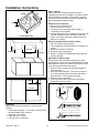
Models and manufacturing numbers in this manual Service Gas Cooktops This manual replaces RS2410001 Rev. 4 Service Manual for Amana Caloric Modern Maid AKO2000 AKS30 AKS3020* AKS3030* AKS3030* AKS3040* AKS3040* AKS3040* AKS3040* AKS3040* AKS3050* CKS3020* GT341 GT451 GT583 KGT341 KGT341 PGT120U PGT153U RTP201 RTP203 RTP300 RTP302 RTP304 RTP305 RTP306 RTP306U RTP307 RTP308U RTP348 RTP349 P1142512N P1142501N P1142517N P1142527N PAKS3030* P1142513N P1142518N P1142522N P1142525N PAKS3040* P1142526N P1142515N P1123230N P1131428N P1142504N P1142506N P1131401N P1142508N P1131494N P1142505N This manual is to be used by qualified appliance technicians only. Maytag does not assume any responsibility for property damage or personal injury for improper service procedures done by an unqualified person. 16021879 Revision 0 August 2002 Important Information Pride and workmanship go into every product to provide our customers with quality products. It is possible however, that during its lifetime a product may require service. Products should be serviced only by a qualified service technician who is familiar with the safety procedures required in the repair and who is equipped with the proper tools, parts, testing instruments and the appropriate service manual. REVIEW ALL SERVICE INFORMATION IN THE APPROPRIATE SERVICE MANUAL BEFORE BEGINNING REPAIRS. IMPORTANT NOTICES ! WARNING If repairs are attempted by unqualified persons, dangerous conditions (such as exposure to electrical shock) may result. This may cause serious injury or death. ! CAUTION Amana will not be responsible for any injury or property damage arising from improper service or service procedures. If you perform service on your own product, you assume responsibility for any personal injury or property damage which may result. To locate an authorized servicer, please consult your telephone book or the dealer from whom you purchased this product. For further assistance, please contact: Customer Service Support Center CAIR Center Telephone Number Web Site W W W .AMANA.COM ..................................... 1-800-843-0304 W W W .JENNAIR.COM .................................. 1-800-536-6247 W W W .MAYTAG.COM................................... 1-800-688-9900 CAIR Center in Canada ............................... 1-800-688-2002 Amana Canada Product ................................ 1-866-587-2002 Recognize Safety Symbols, Words, and Labels ! DANGER DANGERImmediate hazards which WILL result in severe personal injury or death. ! WARNING WARNINGHazards or unsafe practices which COULD result in severe personal injury or death. ! CAUTION CAUTIONHazards or unsafe practices which COULD result in minor personal injury or product or property damage. 16021879 Rev. 0 2 ©2002 Maytag Appliances Company Table of Contents Installation Notes AKS3020, AKS3030, AKS3040, AKS3050, and CKS3020..................13 Countertop Cutout .............................................13 Clearances ........................................................13 Above a Drawer.................................................13 Placing Unit in Countertop.................................13 Adjusting Air Shutter..........................................13 Operating Instructions Using the Cooktop ................................................14 Cooking Utensils...................................................14 Using a Wok .........................................................14 Operating the Cooktop .........................................14 Burner Operation - All Models ...........................14 Top Burner Settings ..........................................15 Flame Adjustment .............................................15 Using Cooktop During Power Failure ................15 Cleaning ...............................................................15 Grates and Caps ...............................................15 Cooktop .............................................................15 Sealed Burners..................................................16 Open Head Burners ..........................................16 Troubleshooting Procedures Chart.....................................................................17 Top Burner Valve..................................................17 Spark Module (Models RTP306 and RTP307).....18 Top Burner Spark Ignitors ....................................18 Gas Pressure and Measurement .........................18 Measuring Gas Pressure......................................18 Using the Manometer ...........................................17 Disassembly Procedures Maintop Removal..................................................19 Models RTP302,RTP304, RTP305,RTP307.....19 Models RTP203 and RTP210 ...........................19 Burner and Related Parts .....................................19 Burners..............................................................19 Burner Control Valve .........................................19 Pilot Fitting (Applicable Models) ........................19 Electronic Spark Module: Models RTP306 and RTP307 ........................19 Spark Module Removal.....................................20 Disassembly Instructions for Models AKS30, AKS3020, AKS3030, AKS3040, AKS3050, CKS3020, PGT153, and RTP308......20 Diecast Burners.................................................20 Maintop..............................................................20 Venturi Assemblies ...........................................20 Spark Module ....................................................20 Burner Ignitor Switches .....................................20 Burner Gas Valve ..............................................20 Manifold.............................................................20 Wiring Diagrams and Schematics AKO2000 ..............................................................21 AKS30, PGT153, and RTP308.............................22 GT341 / PGT120 ..................................................23 GT451...................................................................24 GT583...................................................................25 RTP306 and RTP307 ...........................................26 AKS3020, AKS3030, AKS3040, AKS3050, and CKS3020 .......................................................27 Important Information Introduction General Information ............................................. 4 Model Identification and Ordering Replacement Parts .............................................. 4 New Amana Cooking Products Nomenclature .... 4 Old Amana Cooking Products Nomenclature ...... 4 Modern Maid Cooking Products Nomenclature ... 5 Caloric Cooking Products Nomenclature............. 5 Gas Cooktop Feature Chart................................. 5 Installation Before Installing ................................................... 6 Receiving .......................................................... 6 Unpacking......................................................... 6 Electrical Connections ......................................... 6 Making the Gas Connections - All Models ........... 6 Access to Gas Connection ............................... 6 Pressure Testing the Gas Supply Piping System ............................ 7 Test for Gas Leaks ........................................... 7 Cooktop Conversion to LP Gas ........................... 7 Pressure Regulator Conversion - All Models.... 7 Example One .................................................... 7 Example Two .................................................... 7 Example Three ................................................. 7 Example Four ................................................... 8 Example Five .................................................... 8 Example Six...................................................... 8 Converting Burners to LP Gas - All Models ...... 8 Burner Section - All Models.................................. 9 BTU Input.......................................................... 9 Top Burner Adjustment..................................... 9 Proper Flame Adjustment - All Models ............. 9 Installation Notes RTP308, AKS30, and PGT153 Models .............. 9 Countertop Cutout ............................................ 9 Clearances........................................................ 10 Above a Drawer ................................................ 10 Placing Unit in Countertop ................................ 10 Removal and Replacement of the Cooktop...... 10 Adjust Burner Flame Height.............................. 10 Installation Notes RTP201 and RTP203 Models ............................ 11 Countertop ........................................................ 11 Clearances........................................................ 11 Placing Unit in Countertop ................................ 11 Adjusting Top Pilot............................................ 11 Installation Notes RTP302, RTP304, RTP305, RTP306 and RTP307 Models ............................ 12 Countertop Cutout ............................................ 12 Clearances........................................................ 12 Above a Drawer ................................................ 12 Placing Unit in Countertop ................................ 12 Adjusting Top Pilots (Gas Ignition) ................... 12 Automatic Pilotless Ignition Models .................. 12 ©2002 Maytag Appliances Company 3 16021879 Rev. 0 Introduction General Information Model Identification and Ordering Replacement Parts This manual provides complete instructions and suggestions for handling, installing and servicing Amana gas cooktops. Unit’s model and manufacturing numbers are recorded on its rating label. Rating label is located on the bottom of sealed burner units. On open burner units, rating label is located under maintop. Lift cooktop from front edge to see rating label on top of burner box. Before ordering parts, write down the correct model and manufacturing numbers from rating label. This avoids incorrect shipments and delays. Please refer to parts catalog when ordering replacement parts. Directions, information, and warnings in this manual are developed from experience with, and careful testing of the product. If the unit is installed according to the manual, it will operate properly and will require minimal servicing. A unit in proper operating order ensures the consumer all the benefits provided by clean, modern gas cooking. This manual contains all the information needed by authorized Maytag service technicians to install and service Amana, Caloric, Modern Maid gas cooktops. There may be, however, some parts which need further explanation. Maytag maintains a toll-free technical support line to answer questions from authorized service technicians. To located an authorized service technician, the number is 1-800-628-5782 for Amana products. New Old Amana Cooking Products Nomenclature Brand A - Amana C - Caloric N International Z - Canadian Product K - Cooktop E H R T Fuel/Type Electric - Electric Downdraft - Halogen - Rough Top - Radiant G L O S Gas - Gas Downdraft - Gas Glass - Open Burners - Sealed Burners D F S G Configuration - Double Cartridges - Fixed Cartridges - Single Cartridge - Griddle Width 20 - 20” 30 - 30” 36 - 36” Feature 1 - Least 2 3 4 5 6 7 8 9 - Most Series 0 Color E - Ebony K - Chrome L - Almond W - White LL Almond/Almond SS - Stainless WW White/White Old Amana Cooking Products Nomenclature Product Group G - Gas Wall oven R - Electric Wall oven K - Cooktop CO - Convection Wall Oven O - Wall Oven 16021879 Rev. 0 Product Type 2H-Halogen DG1-Downdraft Gas Smoothtop Cooktop, 1 pc Cooktop, 2 Grate Halogen DH-Downdraft Electric Elements, 1 Cooktop, Optional Dual Halogen Cartridge R-Electric Roughtop DS-Gas or Electric Wall oven, Calrod Downdraft Slide-In Elements Wall oven S-Gas Wall oven, G-Gas on Glass Sealed Burners Cooktop, Sealed T-Radiant Smoothtop Burners Wall oven H-Halogen Smoothtop 2T-Radiant Wall oven, 1 Dual Smoothtop Wall Element oven or Cooktop, 1 Dual Element 4 Features Wall oven FeaturesVariable Cooktop Width ⋅30=30” ⋅35=35” ⋅300=30” reduced depth (20-1/4”) Wall Oven Width/Fuel ⋅24SE2=24” Single Electric (2.9 cu. ft. oven), Soft Look Trim ⋅27SE=27” Single Electric (3.3 cu. ft. oven) ⋅27DG=27” Double Gas (Two 3.3 cu. ft. ovens) Color No Designator-Ebony K-Chrome Top L-Almond LG-Almond, Glass Door W(1*)-White WW-White on White E(1*)-Ebony *Enhancements: Electric Variable Intensity System. Gas One Piece Grates ©2002 Maytag Appliances Company Introduction Modern Maid Cooking Products Nomenclature Product Group D-Dishwasher F-Electric Product G-Refrigerator K-Cooktop M-Microwave Oven P-Gas Product X-Kit or Accessory Product Type ET-Electric Cooktop BR-Backguard Kit (Coil or DC-Electric Downdraft) Single/Double GO-Gas Wall Oven, Convection Wall Manual Clean Oven, Self-Clean GT-Gas Cooktop DO-Electric HO-Double Gas Wall Combination Wall Oven, Self-Clean Oven, Self-Clean HU-Gas Slide-In Wall DU-Electric Slide-In Oven, Self-Clean Wall oven, SelfKO-Gas Wall Oven, Clean Continuous Clean Product Group E-Electric Product R-Gas Range T-Trash Compactor H-Vent Hood M-Microwave Oven D-Dishwasher Product Type R-Microwave/Electric C-Convertible S-Self-Clean H-High Broil T-Cooktop J-Hi-Broil w/Cont. U-Undercounter Cleaning Panels V-Variable Power K-Upper Oven W-Wall Oven w/Cont. Microwave Lower Cleaning Panels - Self-Cleaning Y-Self-Cleaning L-Low Broil M-Low Broil w/Cont. Cleaning Panels P-Portable Series Variable Features Variable Fuel N-Natural Gas Only U-Universal (Set for natural gas) 1-120 Volts, 60 Hz. 2-240 Volts, 60Hz. Color W-White WW-White on White WW1-White on White/1 pc. grate B-Black B1-Black/1 pc. grate L-Almond K-Chrome Top D-Black Glass Fuel N-Natural Gas L-Bottled Gas U-Universal 1-115 Volts 2-240 Volts 8-208 Volts Color 0-No Color 1-White 2-Antique Copper 3-Avocado 4-Autumn 5-Satin/Stainless Steel 6-Black 8-Color Pack 9-Color Pack H-Harvest L-Almond W-White Caloric Cooking Products Nomenclature Series P R D S Features Variable Gas Cooktop Feature Chart Model Burner Ignition Thermoset Burner Tri-Set Controls Hinged Top Overall Dimensions Width AKO2000 AKS30 AKS3020 AKS3030 AKS3040 AKS3050 CKS3020 GT341 GT451 GT583 PGT120 PGT153 KGT341 RTP201 RTP203 RTP300 RTP302 RTP304 RTP305 RTP306 RTP307 RTP308 Spark Spark Spark Spark Spark Spark Spark Spark Spark Spark Spark Spark Spark Pilot Pilot Pilot Pilot Pilot Pilot Spark Spark Spark X X X X X X X X X X X X Depth 29-1/2” 29-1/2” 29-1/2” 29-1/2” 29-1/2” 29-1/2” 21” 21-1/2” 21-1/2” 21-1/2” 21-1/2” 21-1/2” 29-1/2” 21” 23-1/2” 23-1/2” 29-1/2” 29-1/2” 29-1/2” 29-1/2” 29-1/2” 29-1/2” 29-1/2” 19-3/4” 19-3/4” 21” 21” 21” 21” 21” 21” 21” Refer to Rating Label on above models for information on Natural/L.P. gas supply pressure. ©2002 Maytag Appliances Company 5 16021879 Rev. 0 Installation Instructions Before Installing Making the Gas Connection - All Models Installing the gas cooktop in compliance with local electrical and gas building codes results in proper operation and consumer satisfaction with the cooktop. Verify the cooktop installation meets local codes or current American Gas Association requirements in the absence of local codes. When installing CGA units, verify that installation meets local codes or, in absence of local codes, current Natural Gas Installation Code CAN/CGA-B149.1 or current Propane Installation Code, CAN/CGA-B149.2 before connecting to the gas supply system. Receiving Inspect cooktop thoroughly at time of delivery. Immediately report any visible damage to carrier. Damage not discovered until after accepting delivery can still be claimed by using a concealed damage report form, available from the carrier’s agent. Installation in manufactured homes must conform with the standard CAN/CSA-Z240 Mobile Homes, Manufactured Home Construction and Safety Standards, Title 24CFR, Part 3280, or with local codes if applicable. All shipments, i.e., complete cooktop or parts, are shipped at the buyer’s risk. Amana responsibility ends when the consignment is accepted by the carrier in “good order.” Amana supports damage claims by supplying invoices, bills of loading and other documentation as needed. Providing this assistance, however, does not imply any responsibility for settling claims. Do not deduct claims for loss or damage from the invoice and do not withhold payment pending adjustment of claims. Do not return any units or parts for credit without written consent. ! WARNING To avoid risk of personal injury or property damage. Use only new flexible connectors design certified by the AGA or CGA. Do not reuse an old connector. Do not reuse old connector when moving the appliance. Unpacking Open one end of the carton. Remove all literature packed with the cooktop and slide cooktop onto a flat surface. Avoid countertop damage by NOT sliding cooktop across the countertop. Remove grates, burner caps and pressure regulator from the carton. Access to Gas Connection Install a manual shut-off valve in an accessible location outside the cooktop. Shut-off valve not supplied with cooktop. Electrical Connection Connect the gas supply line either using hard piping or a properly-certified flexible connector. The pressure regulator supplied with cooktops have a 1/2 inch NPT female connection. Check local codes before choosing a method. Use a pipe joint compound resistant to the action of propane gas on all male threads. Models with automatic pilotless (spark) ignition require an external electrical source that must be grounded and polarized in accordance with local codes. Use National Electrical Code, ANSI/NFPA No. 70-Latest Edition in the absence of local codes. The wall receptacle must be placed within easy reach of the power cord without interfering with the gas supply line. ! Do not overtighten the fitting on the pressure regulator. Overtightening may crack the regulator. Cooktops must be properly grounded. Cooktop power cords are equipped with a three-prong grounded plug. They fit standard three-prong wall receptacles. ! WARNING WARNING To avoid risk of serious electrical shock or property damage. Do not cut or remove the third (grounded) prong from the power plug. The consumer is responsible for replacing any standard two-prong wall receptacle with a grounded and polarized three-prong wall receptacle. A qualified electrician should check any receptacle the customer doubts is properly grounded. The wiring diagram is on the bottom of the cooktop. 16021879 Rev. 0 6 ©2002 Maytag Appliances Company Installation Instructions Pressure Testing the Gas Supply Piping System Disconnect the cooktop from the house gas supply piping system during any pressure test exceeding 1/2 psig (3.5kPa). Example One 1. Remove pressure regulator cap with a 7/8-inch wrench. 2. Remove plastic insert from cap. Insert fits tightly in cap. 3. Reverse plastic insert. Push firmly into hole in cap. 4. Verify insert fits tightly in hole. Do not disturb spring in regulator body. 5. Replace cap in regulator body. Use the manual shut-off valve to isolate the cooktop from the supply system during pressure tests at pressures equal to or less than 1/2 psig (3.5kPa). The gas supply pressure for checking the regulator setting is to be at least 1 inch WCP above pressure on rating label. Test for Gas Leaks Test for leaks after making final gas connection by closing all burner valves and turning on the gas supply. Test for leaks by applying soap suds to all gas connections in the supply line and in the cooktop. Bubbles appear when there is a leak. If bubbles indicate a leak, shut off the gas supply valve. Fix the leak by tightening the joint or by unscrewing the joint and applying additional pipe joint compound. Open the gas supply valve and retest for leaks. Retest for leaks on any joints disturbed. ! Natural Gas L.P. Gas Plastic Insert Cover Spring Location Example Two 1. Remove cap with screwdriver. 2. Remove insert. 3. Reverse insert and replace. “LPG10” is visible. Do not disturb spring in regulator body. 4. Replace cap. DANGER To avoid risk of property damage serious personal injury or death. Never use a lit match to check for leaks. Cooktop Conversion to LP Gas Cap Amana, Caloric and Modern Maid gas cooktops are configured at the factory to use natural gas. The cooktops featured in this manual may be modified to use LP gas supplies. Modifying the gas supply pressure regulator and individual burner valves enables these units to use LP gas. Plug Spring Pressure Regulator Conversion - All Models Amana uses several types of gas pressure regulators for cooktop units. Each type, however, performs the same function. Universal pressure regulators, which equip all cooktops featured in this manual, enable connection to either natural gas or LP gas supplies. Cooktops are set at the factory to use natural gas; no modification is necessary. Modification, however, is necessary when connecting a cooktop to an LP gas supply. How each type of universal pressure regulator is converted to LP use is explained and illustrated in the following examples. L.P. Gas Natural Gas Example Three 1. Remove cap marked “Nat.” 2. Reverse cap. “LP” now appears on cap. 3. Reinsert cap. Do not disturb spring beneath the cap. Verify fiber washer is correctly between cap and the regulator body. NOTE: Some models may not have washers. If washer is not supplied, none is needed. Cap Spring Natural Gas ©2002 Maytag Appliances Company 7 L.P. Gas 16021879 Rev. 0 Installation Instructions Converting Burners to LP Gas All Models Universal units have double coaxial orifices sized for natural gas. Converting these orifices requires tightening the orifice hood as described below. 1. Remove grates, burner caps, knobs and control panel. 2. Remove or lift up maintop. 3. Remove venturi assemblies. Orifice hoods become accessible. 4. Turn clockwise each orifice hood approximately 1-1/2 to 2 turns. Orifices should fit snugly on the pins. Do not damage or distort the hole through pin center by overtightening. Example Four 1. Remove cap with screwdriver slot. 2. Reverse and replace cap. Verify “LPG10” is visible. 3. Do not disturb spring beneath cap. Cap Spring Natural Gas L.P. Gas Example Five 1. Remove cap with screwdriver slot. 2. Remove black insert marked “NAT.” from cap. Insert fits tightly in cap. 3. Reverse insert. 4. Replace in hole. Verify “LP” is visible. Verify that insert is pressed firmly into shoulder. Do not disturb spring in regulator body. 5. Replace cap in regulator body and tighten. Pin L.P. Gas Natural Gas Orifice Hood Cap Insert Universal Burner Orifice L.P. Gas Spring L.P. Gas Natural Gas Universal Burner Orifice Natural Gas 5. Replace venturi assemblies, maintop, controls panel, knobs, burner caps and grates. Example Six 1. Remove cap with screwdriver slot. 2. Remove spring and washer. Washer will be at bottom of spring as illustrated below. 3. Reverse to bring washer to the top. 4. Reinstall spring and washer. 5. Tighten cap. ! CAUTION Do not overtighten orifice hood. Damage to pins inside the orifice hoods may result if hoods are overtightened. Cap Washer Natural Gas 16021879 Rev. 0 L.P. Gas 8 ©2002 Maytag Appliances Company Installation Instructions A proper flame is set by adjusting the air shutters for each burner. Air shutter adjustment is described below. 1. Remove grates, burner caps, knobs and control panel. 2. Remove or lift up maintop. 3. Loosen lock screw on air shutter. 4. Opening air shutter increases air to flame. Closing air shutter decreases air to flame. 5. Replace maintop, control panel, burner caps, knobs, and grates. Burner Section - All Models BTU Input Models AKS30, PGT153 and RTP308 feature a pair of large and small burners each. The hourly BTU input for the larger burners is 9,000 when connected to a natural gas supply and 8,000 when connected to an LP gas supply. The BTU input for smaller burners is 7,000 when connected to a natural gas supply and 6,000 when connected to an LP gas supply. Other models with just a single size burner is rated at 10,000 when connected to a natural gas supply and 9,000 when connected to an LP gas supply. Refer to rating label for specific information. Top Burner Adjustment Air shutters must be adjusted for proper flame. Loosen the air shutter lock screw and adjust the air shutter until the flame’s inner cone is blue-green and its outer mantle is dark blue. Sealed Burner Lock Screw OpenHead Burner Air Shutter Installation Notes RTP308, AKS30, and PGT153 Models Adjusting pilot burners and locating adjustment screws for models with pilot lights are covered in installation notes for those models. A properly adjusted pilot flame means the burner will correctly ignite. Problems caused by delayed ignition are avoided. Countertop Cutout Prepare the countertop opening for the unit according to the dimensions as illustrated. The cooktop requires a base cabinet with a minimum width of 30 inches. Proper Flame Adjustment - All Models For the best results, each burner should display a proper flame. A proper flame has a blue-green inner core, a dark blue outer mantle and a soft appearance. Cabinet Base Min. width 30" 1-3/8" 27-5/8" 20" 13-3/4" 1-1/2" ©2002 Maytag Appliances Company 9 16021879 Rev. 0 Installation Instructions Above a Drawer Allow a three inch clearance between the top of countertop and the top of a drawer or any other cabinet feature beneath the cooktop. There must be enough clearance to accommodate the pressure regulator and make adjusting the regulator easier. 21" 29-1/2" 2-7/8" Placing Unit in Countertop 1. Set unit into countertop cutout. 2. Center burner box in cutout. 3. The burner box’s front edge and the edge of countertop must be parallel. 4. Locate holding tabs on the underside of cooktop. Pull each tab outward to form a 90 degree angle with bottom of cooktop. Tabs keep cooktop from being lifted out of cooktop. Overall Dimensions Removal and Replacement of the Cooktop 1. Shut off electrical and gas supply. 2. Turn holding tabs on the underside of the burner box inward. 3. Disconnect electrical connection. 4. Disconnect gas supply piping. 5. Replace cooktop by following steps listed under the previous heading. 30" min. 13" max. 30" min. 18" min. Adjust Burner Flame Height The low burner flame should be a steady blue flame approximately 1/4 inch in length. Make adjustments with the adjustment screw in the center of valve stem. Valve stem is directly behind the control knob. 1. Remove burner control knob by pulling straight up from valve stem. 2. Hold valve stem stationary. Turn screw in center of knob stem with flat blade screwdriver until flame is approximately 1/4 inch long at low setting. 3. Replace burner control knob. 4. Turn control knob from low to high to test flame. Check flame at each setting. 1-5/8" Valve Adjustment Screw 12-3/4" Shaft Clearances Observe the following clearances to safely operate cooktop. • Side by side cooktops - 5-7/8 inches, measured from the side flanges of the maintops. • Rear wall - 1-3/8 inches • Right side wall - 1/4 inch • Left side wall - 5-7/8 inches 16021879 Rev. 0 Low Flame High Flame 10 ©2002 Maytag Appliances Company Installation Instructions Placing Unit in Countertop Unpack all parts. Access the burner compartment by removing the maintop as follows: 1. Remove top grates, burner bowls and burner knobs. 2. Unlatch maintop from burner box by pressing down on four release catches located inside burner openings as shown. Installation Notes RTP201 and RPT203 Models Countertop Cutout Prepare countertop opening for these models as illustrated below. 23-1/2" 19-3/4" Press Press 2-1/8" Press 18" Press 22-1/4" Top Release Catches Overall Dimensions 3. Lift maintop by grasping between two burner openings and lifting up. 4. Set unit into countertop cutout. 5. Center burner box in cutout. Front edges of burner box and countertop must be parallel. 6. Secure to countertop with screws. Clearances Observe the following clearances to safely operate cooktop. • Side by side cooktops - 5-7/8 inches, measured from the side flanges of the maintops. • Rear wall - 1-3/8 inches • Right side wall - 1/4 inch • Left side wall - 5-7/8 inches Adjusting Top Pilot 1. Turn pilot adjustment screws clockwise until fully closed. 2. Turn pilot adjusting screws 1-1/2 turns counterclockwise. 3. Light pilots. 4. Adjust until flame tips are even with center of flash tubes as shown below. Above a Drawer Allow a three inch clearance between the top of countertop and the top of a drawer or any other cabinet feature beneath cooktop. There must be enough clearance to accommodate the pressure regulator and make adjusting the regulator easier. Flash Tube Pilot Flame Pilot Adjustment Screw ©2002 Maytag Appliances Company 11 16021879 Rev. 0 Installation Instructions Clearances Observe the following clearances to safely operate the cooktop. • Side by side cooktops - 5-7/8 inches, measured from the side flanges of the maintops. • Rear wall - 1- 3/8 inches • Right side wall - 1/4 inch • Left side wall - 5-7/8 inches Installation Notes RTP302, RTP304, RTP305, RTP306, and RTP307 Models Countertop Cutout Cut countertop opening for unit according to dimensions illustrated below. A 30 inch minimum base cabinet is required. Cabinet Base Min. width 30" Above a Drawer Allow a three inch clearance between the top of the countertop and the top of a drawer or any other cabinet feature beneath the cooktop. There must be enough clearance to accommodate the pressure regulator and make adjusting the regulator easier. 2-3/16" 27-5/8" 19-3/8" Models RTP306 and RTP307 have an electrical supply cord and an electrical supply box. It is important that the wall receptacle be located within the cabinet cutout specifications. 13-13/16" 2-3/8" Placing Unit in Countertop Remove all literature packed with cooktop. To access the burner compartment do the following. 1. Remove the carton containing the maintop and grates from the top of the cooktop. 2. Remove packing material and tape securing control panel to burner box. 3. Set unit into countertop cutout. 4. Center burner box in cutout. Front edges of burner box and countertop must be parallel. 5. Secure to countertop with screws. 21" 29-1/2" 2-1/8" Adjusting Top Pilots (Gas Ignition) 1. Turn pilot adjustment screws clockwise until closed. 2. Turn pilot adjust screws 1-1/2 turns counterclockwise. 3. Light pilots. 4. Adjust until flame tips are even with center of flash tubes as shown below. Electrical box on models with automatic pilotless ignition, require two additional inches of clearance underneath. Flash Tube 1-5/8" Pilot Flame 12-3/4" Pilot Adjustment Screw Automatic Pilotless Ignition Models Turn gas valve for one of the top burners fully counterclockwise starts an electrode between the flash tubes sparking. The sparking continues as long as the knob is in this position. Turn the knob to the “HI” position after burner lights. The electrode will stop sparking. There are no standing pilots to light or adjust. Models with ignitor coils operate similarly except the ignitor coil will glow. 16021879 Rev. 0 12 ©2002 Maytag Appliances Company Installation Instructions Installation Notes AKS3020, AKS3030, AKS3040, AKS3050, and CKS3020 Models Countertop Cutout Cut countertop opening for unit according to dimensions illustrated below. A 24 inch minimum base cabinet is required. AKS3040 AKS3020 1-3/8" Cabinet Base Min. width 24" CKS3020 2-1/2" 19-3/16" AKS3040 AKS3020 1-1/8" 28-1/2" CKS3020 2-5/16" Front 21-1/2" 29-1/2" 2-7/8" 2" 2" 7-1/8" down from top of cutout Countertop Burner box Bracket Tinnerman nut Adjusting screw ©2002 Maytag Appliances Company screw holds bracket to burner box. Clearances Observe the following clearances to safely operate the cooktop. • 30” to bottom of cabinet. • Rear wall1-3/8 inches • Right side wall5-7/8 inches • Left side wall5-7/8 inches • Front dimensions1-1/8” AKS3020, AKS3030, AKS3040, AKS3050 2-5/16” CKS3020 • 3” from top of countertop to drawer or other obstruction under countertop. • With pressure regulator, drawer must be shorted or rear of drawer must be cut for clearance. • Minimum of 6-1/4” must separate side flanges of cooktops installed side by side. Above a Drawer Allow a three inch clearance between the top of the countertop and the top of a drawer or any other cabinet feature beneath the cooktop. There must be enough clearance to accommodate the pressure regulator and make adjusting the regulator easier. Placing Unit in Countertop Remove all literature packed with cooktop. 1. Remove burner grates and caps. 2. Remove screws securing burners to cooktop. 3. Unplug terminal connections from burners. 4. Remove maintop from burner box. 5. Locate 4 holes, one in each corner. 6. Drill hole through holes in flange into countertop. • Use size 5/64” drill bit. • Do not drill through countertop. 7. Insert screws provided into holes and tighten until cooktop is secure. Securing Cooktop to Countertop 1. Locate 3 installation bracket assemblies on bottom of burner box. Each assembly consists of a bracket and tinnerman nut attached to the burner box by a screw. 2. Loosen screw which holds bracket to burner box a 1/4 turn. Rotate bracket so tinnerman nut is directly beneath countertop. Tighten screws securing bracket to burner box. 3. Obtain adjusting screws (three 4-inch machine screws) and install screws into tinnerman nuts, tighten adjusting screws to secure countertop. Adjusting Air Shutter 1. Remove control knobs, grates, caps, and burner bowls. 2. Remove screws securing burners to cooktop, and unplug terminal connections from burners. 3. Lift top off burner box to expose air shutters. 4. Slide air shutter open or closed depending on appearance of burner flame. • If flame is yellow and does not hold its shape, open air shutter. • If flame is blowing or noisy, close air shutter. 5. Reassemble in reverse order. 6. After adjustment retest burner flames. 13 16021879 Rev. 0 Operating Instructions Using the Cooktop Using a Wok • Use Proper Pan Size Use cooking utensils with flat bottoms large enough to cover the flame. Correct-sized utensils improve cooking efficiency and promotes safety. Undersized utensils expose clothing and spillovers to direct flame. • Never Leave Surface Units Unattended At high heat settings, boilovers can cause smoking or fire. • Glazed Cooking Utensils Use glass, glass/ceramic, earthenware or other glazed utensils for cooking. Sudden temperature changes may break some utensils. • Turn Utensil Handles Inward A handle extending from the cooktop invites accidents. Do not use a wok with a ring stand. A wok with a ring stand does not allow the proper air/gas mixture while cooking. Use only a flat bottom wok. Flat Bottom Wok Cooking Utensils Utensils made of different materials react differently to cooking temperatures. The best results occur by matching cooking utensil and cooking style. The following list describes the cooking characteristics of various materials. • Glass/ceramic responds slowly to temperature changes. It responds best to long and slow heating of liquids. • Aluminum responds quickly to temperature changes. It responds best for frying, braising and roasting. • Cast iron responds slowly to temperature changes. It responds best for long low heat cooking and pan frying. • Stainless steel combined with another metal such as copper, responds better to temperature changes. Use stainless steel for soups, sauces, vegetables and general cooking. • Copper, tin-lined utensils respond quickly to temperature changes. It is excellent for gourmet cooking, wine sauces and egg dishes. • Enamelware is stain resistant porcelain over metal. The cooking time varies according to the base metal. Lower temperatures are usually recommended. • Utensil design is important. Select utensils with flat bottoms, straight sides, handle weight that does not tilt the pan, and pans that match the burner size. Do not use pans that exceed the diameter of the burner. Ring Stand Wok Operating the Cooktop Burner Operation - All models 1. Push in and turn control to LITE. Burner sparks. 2. Burner lights automatically. 3. Turn knob to desired setting. Sparking stops. Turn burner control to any position, except LITE, to set flame. 4. Turn control to OFF when finished. OFF LO W MED HI LITE Typical Control Knob 16021879 Rev. 0 14 ©2002 Maytag Appliances Company Operating Instructions Top Burner Settings Check the burner for correct flame size and shape. Set burner on LOW. Adjust flame to approximately 1/4 inch length. Turn flame from LOW to HIGH several times to verify that burner stays lit. The flame should be soft. There should be no blowing or lifting. Using Cooktop During Power Failure Although the system used to light the burner is electric, the burner can be used during prolonged power outages. Follow the instructions below. 1. Hold a lit match at desired burner. 2. Push in and turn control to LITE. When burner lights, turn control to desired setting. 3. When finished cooking, turn all controls to OFF. Cleaning Do not clean cooktop until it cools. Sudden temperature changes can crack the porcelain or enamel cooktop surface. Washing the cooktop with hot, soapy water after each use minimizes the need for heavy cleaning. To preserve the original appearance, rinse and wipe the surfaces dry after washing. Low Flame Wipe up marinades, fruit juices, vinegar and milk spills to avoid permanent stains. These materials contain acids and cause discoloration and permanent staining. DO NOT touch any portion of the cooktop when it is hot. Wait and wipe up spills after the cooktop is cool. High Flame Proper Flame Size Grates and Caps Clean grates and caps with a damp cloth and soapy water. Nonabrasive cleaners or pads may be used. DO NOT use harsh powders, scouring pads or steel wool pads. Never use oven cleaners on the grates or any other part of the cooktop. For burned or dried on spillovers, soak grates in warm soapy water. The HIGH flame should be a steady flame with a distinct inner cone. There should be no blowing or lifting. Use the adjustment screw in the valve stem if LOW burner flame is not steady and approximately 1/4 inch long. Flame Adjustment 1. Remove control knob. 2. Using a small, flat blade screwdriver, turn screw located in center of knob stem until flame is the proper size. 3. Replace control knob. 4. Turn control from LOW to HIGH several times and check flame at each setting. Dry all components to prevent rusting. Replace grates and burner bowls. Verify that burner ports are not blocked. Cooktop Clean cooktops with a damp cloth and soapy water. A nonabrasive cleaner or pad may be used. Do not use harsh powders, scouring pads or steel wool pads. Never use oven cleaners on porcelain cooktop. Clean the cooktop regularly. Valve Adjustment Screw Dry the top thoroughly. Stainless steel cooktops may be coated with a stainless steel protectant. Call Amana Consumer Affairs for a recommendation. Shaft ! WARNING The flame should not extend beyond the edge of the cooking utensil. It may contact clothing or pot holders and cause a fire. ©2002 Maytag Appliances Company 15 16021879 Rev. 0 Operating Instructions Sealed Burners Clean burners with a damp cloth and warm soapy water. A nonabrasive cleaner or pad may be used. Verify that burner ports are not blocked. Open Head Burners Open head burners can be removed for cleaning. Maintop and burners must be cool before cleaning. 1. Remove grates. Lift or remove maintop. 2. Grasp burners at burner head. Lift upward and away. Do not block the small slot above the ignitor. A blocked slot results in poor burner ignition. Replace burner caps correctly. Open head burners may fail to perform properly if ports are clogged or plugged. Use warm water and soap to clean. Soaking loosens burned on materials. Clear clogged burner holes with a thin wire. Do not use toothpicks to clean burner holes. Dry all burner components to prevent rusting. Allow ignitors to dry before lighting burners. Burners must be completely dry before being used again. Water logged burner parts might cause uneven heating or interfere with automatic lighting. Burner Cap Ignitor Slot Flame Port Holes/Slots Ports Ignition Port Holes Burner Body Cleaning Sealed Burners Flashing Tube Cleaning Open Head Burners 16021879 Rev. 0 16 ©2002 Maytag Appliances Company Troubleshooting Procedures In the following procedures, correct gas pressure should be first determined (natural or LP gas). Problem 1. Burner will not ignite. 2. Burners will not ignite. “Spark” at top burner ignitors. Probable Cause • Top pilots not lighted, or ignitors not operating. • Orifice hoods are clogged. • Burner venturi, burner cap or burner ignition ports clogged. • Burner venturi, burner cap or burner ignition ports clogged. • Air shutters out of adjustment. • Burner flame not correctly adjusted. (LP Gas) 3. Burners will not ignite. No “Spark” at burner ignitors. Burner knob pushed down, turned to and held in LIGHT position. • No 120 VAC to range. • Circuit breaker or fuse blown. • Microswitch contacts not closing. • Faulty wiring. • Inoperative spark module. • Ignitor ceramic dirty, spark gap out of adjustment. Correction • Light top pilots, or correct ignitor operation. • Clean orifice hoods and verify size in use is correct. • Clean burner venturi, cap or ignitor port. • Clean burner venturi or ignition ports. • Adjust air shutters according to installation instructions. • Adjust burner flame according to LP conversion information in installation instructions. • Check electric at wall outlet. • Reset circuit breaker or replace fuse. • Check activator movement, replace microswitch. • Check wiring against appropriate wiring diagram and be sure all terminals and connections are tight. • Check module according to information in the following section. • Clean ceramic, check grounding strap spark gap according to information in the following section. Top Burner Valve Tri-Set burner valves are standard for all models except RTP203, and RTP201. ©2002 Maytag Appliances Company 17 16021879 Rev. 0 Troubleshooting Procedures Spark Module (Models RTP306 and RTP307) Gas Pressure and Measurement The spark module for the automatic pilotless ignition (spark) system on models RTP306 and RTP307 is located at the bottom rear of the unit. It is housed in the electrical box. The module is accessed by removing two screws holding the electrical box to the unit, which detaches the electrical box. Disconnect electrical power before attempting to remove the box. Correct burner ignition and operation depend upon adequate gas pressure. Amana, Caloric and Modern Maid cooktop regulators are designed to provide proper pressure. Refer to Rating Label for pressure supply. These units are set at the factory for natural gas. The gas regulator and gas valves on these units may be converted when connected to LP/propane gas. In the event of “NO SPARK” verify that the ignitor ceramic is clean and the gap between ignitor and ignitor grounding bracket dimple is 1/8” (-1/32”, +0). 1. Check AC line fuse, or circuit breaker. 2. Disconnect electricity at disconnect plug, and turn off gas supply to cooktop. 3. Using wiring diagram, verify all terminals and wire connections are correct and tight. 4. Set meter on VAC scale. 5. Attach one meter lead of test meter to the black wire terminal on spark module. 6. Attach remaining lead to white wire terminal on spark module. 7. Reconnect electricity at main disconnect plug. 8. Turn all top burner knobs to their light positions. 9. No line voltage at test meter indicates an electrical circuit interruption before spark module. 10.If line voltage is at test meter then check ignitors. 11.If ignitors are OK; replace ignition module. The minimum supply pressure to the regulator must be at least 7 inches WCP for natural gas and 11 inches WCP for LP/propane gas. The maximum pressure cannot exceed 14 inches WCP. Measuring Gas Pressure Measure gas pressure by using pressure meters and gauges or by using a manometer. The following directions apply to using a manometer. If pressure meters and gauges are used, follow directions supplied with those units. Using the Manometer A manometer is a U-shaped tube of clear plastic or glass. Between the two “legs” of the U is a scale measured in inches. Fill the tube with water until the water level reaches “0” on both legs. Connect one leg of the tube to the range manifold or gas valve orifice. Leave the other leg open. Applying gas pressure pushes down the water on one side and up on the other side. Top Burner Spark Ignitors 1. Disconnect electricity at main disconnect plug. 2. Disconnect two spark ignitor leads from spark module terminals. 3. Set ohmmeter on the RX1 ohm scale (adjust to zero). 4. Attach one meter lead to a good ground (bare metal) on the cooktop. 5. Touch remaining meter lead to each terminal of ignitor lead. A continuity reading from either ignitor lead indicates the ignitor lead is shorted to ground. Replace ignitor lead. If no continuity reading from either ignitor lead to ground, then proceed to Step 6. 6. Attach one meter lead to one terminal to the ignitor lead and touch the remaining meter lead on the opposite end of the ignitor lead that is attached to the top burner mounting bracket. Repeat same procedure with the other ignitor lead. No continuity on either lead indicates an open circuit in the ignitor lead wire. Replace ignitor lead. 16021879 Rev. 0 The procedure for taking a gas pressure measurement is simple. Connect the tubing from one leg of the manometer to the gas valve orifice hood. Bleed off trapped air by inserting a small screwdriver blade briefly under the connecting tubing. Trapped air could give an inaccurate reading. Turn on gas valve. Take a full load reading by turning on all top burners to verify that pressure under full load is still within specifications. Gas pressure is measured in WCP by adding the readings from both tubes. If water level on both legs is at the two inch mark, this indicates a pressure of 4 inches WCP that conforms with cooktop specifications as specified on rating label. 18 ©2002 Maytag Appliances Company Disassembly Procedures ! Pilot Fittings (Applicable Models) 1. Remove maintop. 2. Turn pilot gas off at pilot adjusting screw. 3. Remove tubing nut at pilot assembly. 4. Remove pilot shield on channel and cone in pilot cup. 5. Pilot assembly can be removed from the bottom. 6. When replacing the pilot, verify that the tubing connection on pilot assembly faces toward pilot tubing. 7. Open and adjust pilot adjusting screw. WARNING To avoid risk of electrical shock, serious personal injury or death. Make sure oven is properly grounded and polarized. Always disconnect electrical supply before servicing unit. Maintop Removal Models RTP302, RTP304, RTP305, RTP307 These models feature a hinged maintop to make cleaning easier. The hinge is on the rear of the maintop. Lift from the front to access the burner box. Some models feature a support rod that holds the maintop up. For complete maintop removal proceed as follows: 1. Verify that maintop and grates are cool. 2. Remove all grates. 3. Raise the maintop to about a 60 degree angle. 4. Lift maintop up from hinges. ! To avoid risk of electrical shock, serious personal injury or death. Make sure oven is properly grounded and polarized. Always disconnect electrical supply before servicing unit. NOTE: Whenever a component or tubing with threaded ends or fittings is serviced or replaced, apply a good quality, gas-resistant pipe dope or sealant compound to the threads to minimize gas leaks. A sealing tape compatible with LP gas may also be used to seal joints. Models RTP203 and RTP201 These models are not provided with rear hinges. To remove the maintop proceed as follows: 1. Verify maintop and grates are cool. 2. Remove burner bowls and grates. 3. Lift off control knobs. 4. Unlock maintop by releasing catches located in each burner opening. 5. Grasp maintop between burner openings. Lift upward to remove maintop. Electronic Spark Module: Models RTP306 and RTP307 The automatic pilotless ignition (spark) system is employed in models RTP306 and RTP307. It consists of an electronic spark module, burner spark ignitors and an actuator switch assembly on the control valves. When any gas control valve is turned to ignition position (LIGHT), gas flows to the burner. A cam on the control activates the spring loaded actuator and switch, completing a 120 VAC power circuit to the spark module. A separate lever switch is found on thermoset control valves, connected in parallel with the main actuator switch. These valves operate differently than the standard valve with respect to rotation of the control shaft. Burner and Related Parts Burners 1. Verify that maintop and grates are cool. 2. Remove maintop or raise it to access burners. 3. If necessary, remove Phillips head shipping screws securing burners to mounting brackets at burner heads. 4. Lift burner up and away from control valve. 5. When replacing burners, verify each is properly positioned with respect to ignition flash tubes and control valve. Test for proper ignition of burner. When power is applied to the module, a repeated momentary high voltage is fed through the output leads to the spark gap ignitors located between the burner flash tubes. The resultant spark across the gap ignites the gas present at the flash tube and the burner. The spark module is mounted inside the electrical box on the bottom rear of the assembly. Burner Control Valve 1. Turn off gas and electrical supply. 2. Remove grates, maintop and burners. 3. Remove actuator switch assembly on applicable models. 4. Unscrew valve from manifold. ©2002 Maytag Appliances Company WARNING 19 16021879 Rev. 0 Disassembly Procedures Spark Module Removal 1. Disconnect unit from electrical power source. 2. Remove electrical box cover secured by two screws. 3. Disconnect lead wires to the spark module and remove. 4. Reverse procedure to reassemble. When installing spark module, verify that lead wires are correctly connected to the unit. See spark module wiring diagram located beneath unit. Burner Ignitor Switches 1. Disconnect electric and gas supplies. 2. Remove diecast burners. (See Diecast Burners, section.) 3. Remove maintop. (See Maintop, section.) 4. Disconnect lead wires. 5. Pull burner ignitor switches from burner valves. 6. Reverse procedure to reinstall. Verify that lead wires are correctly connected. Disassembly Instructions for Models AKS30, AKS3020, AKS3030, AKS3040, AKS3050, CKS3020, PGT153, and RTP308 Burner Gas Valves 1. Disconnect electric and gas supplies. 2. Remove diecast burners. (See Diecast Burners, section.) 3. Remove maintop. (See Maintop, section.) 4. Disconnect lead wires from spark switch. 5. Pull burner ignitor switches from burner valves. 6. Using an appropriate wrench, remove bolts with washers securing burner valves to manifold. 7. Reverse procedure to reinstall. Verify that lead wires are correctly connected to spark switch. 8. Test for leaks with soap solution or leak tester. Diecast Burners 1. Disconnect electric and gas supplies. 2. Lift off grates and burner caps. 3. Remove phillips screw securing sealed burner to maintop. 4. Lift sealed burners high enough to pull wire from electrode. 5. Reverse procedure to reinstall. Manifold 1. Disconnect electric and gas supplies. 2. Disconnect gas pressure regulator from unit. 3. Remove diecast burners. (See Diecast Burners, section.) 4. Remove maintop. (See Maintop, section.) 5. Disconnect lead wires from spark switches. 6. Pull off surface burner ignition switches. 7. Remove burner gas valves. 8. Disconnect screw from each manifold mounting brackets. 9. Lift manifold and inlet seal from bottom. 10.Reverse procedure to reinstall. 11.Test for leaks with soap solution or leak tester. Maintop 1. Disconnect electric and gas supplies. 2. Lift off grates, burner caps, control knobs and control panel. 3. Remove diecast burners. (See Diecast Burners, section.) 4. Remove phillips screws securing maintop to venturi assemblies. 5. Remove phillips screws securing maintop to manifold support brackets. 6. Lift off maintop. 7. Reverse procedure to reinstall. Venturi Assemblies 1. Disconnect electric and gas supplies. 2. Remove diecast burners. (See Diecast Burners, section.) 3. Remove maintop. (See Maintop, section.) 4. Remove phillips screws securing venturi assembly to burner box. Repeat for each assembly. 5. Lift out venturi assemblies. ! DANGER To avoid risk of property damage, serious injury, or death. Do not test for leaks with an open flame. Spark Module 1. Disconnect electric and gas supplies. 2. Remove diecast burners. (See Diecast Burners, section.) 3. Remove maintop. (See Maintop, section.) 4. Remove screws securing spark module to burner box. 5. Disconnect lead wires to spark module and remove. 6. Reverse procedure to reinstall. When installing spark module verify that lead wires are correctly connected to unit. 16021879 Rev. 0 20 ©2002 Maytag Appliances Company Wiring Diagrams and Schematics ! WARNING To avoid risk of electrical shock, personal injury, or death, disconnect power to cooktop before servicing, unless testing requires it. Neutral L1 Green Spark Switches L1 Spark Module N 2 1 Electrode SCHEMATIC Ribbed or Striped Side of Cord Main Input 3 SKT Cap 3 Pin Plug 1 1 2 2 3 3 WH SF2 Power Cord RD SF2 RD SF2 RD SF2 Spark Switches Color 1 Color Symbol RD WH GN Red White Green NOTES: 1. All wires are 18 GA, 150 C XL unless otherwise noted. SF2 is SEW-2/SF2 200 C rated 2. See serial plate for input ratings. 3. All replacement wires must have same ratings as original wires. ©2002 Maytag Appliances Company L1 RD SF2 High Voltage Wire Spark Module N 2 GN SF2 Electrode WIRING DIAGRAM Spark Module Circuit for AKO2000 Part Number 35-315140-04-0 21 16021879 Rev. 0 Wiring Diagrams and Schematics ! WARNING To avoid risk of electrical shock, personal injury, or death, disconnect power to cooktop before servicing, unless testing requires it. NOTE: 1. All wires 18GA, 150 C XL unless otherwise specified. 2. All replacement wires must have same ratings as original wires. Neutral Line ON GN VT BK L N Spark Module High Voltage Output Manifold Switches 1 Surface LF Electrodes 2 3 4 RF LR RR SCHEMATIC Power Supply 120 VAC 60 Hz Ribbed Side of Cord GN 105 C Chassis BK Splice Connector BK LF VT BK RF Manifold Switches VT L BK BK Spark Module N VT LR RR High Voltage Output VT 1 2 3 4 LF RF LR RR 22 GA Hi Voltage 250 C Burner Electrodes All wires 18 GA, 150 C, X-Linked, Except where noted. WIRING DIAGRAM Electirc ElectricIgnitor IgnitorCircuit Circuitfor forAKS30, AKS30,PGT153, PGT153,and andRTP308 RPT308 Part Number 35-308249-04-0 Part Number 35-308249-04-0 16021879 Rev. 0 22 ©2002 Maytag Appliances Company Wiring Diagrams and Schematics ! WARNING To avoid risk of electrical shock, personal injury, or death, disconnect power to cooktop before servicing, unless testing requires it. N L1 Switches Ignitor SCHEMATIC G Supply Cord Disconnect R R W R Spark Module L1 N 1 2 Switches Code Color R Red W White GA Type SF 18 18 SF Electrode G WIRING DIAGRAM Spark Module Circuit for GT341 / PGT120 Part Number 81-05-483 ©2002 Maytag Appliances Company 23 16021879 Rev. 0 Wiring Diagrams and Schematics ! WARNING To avoid risk of electrical shock, personal injury, or death, disconnect power to cooktop before servicing, unless testing requires it. N L1 Switches Module SCHEMATIC G Supply Cord Disconnect 1 2 3 BL 1 2 3 BL BL Switches BL W BL L1 1 BL Code Color BL Blue W White N 2 Spark Module Electrodes GA Type 18 SEW 18 SEW WIRING DIAGRAM Spark Module Circuit for GT451 Part Number 35-042914-04-0 16021879 Rev. 0 24 ©2002 Maytag Appliances Company Wiring Diagrams and Schematics ! WARNING To avoid risk of electrical shock, personal injury, or death, disconnect power to cooktop before servicing, unless testing requires it. L N Valve Switches Spark Module 9 8 7 6 SCHEMATIC BL BL Valve Switches 3 2 1 Disconnect Electrodes 3 2 1 Spark Module 9 8 7 6 L BL N L N W Power Cord Code Color BL Blue W White GA Type 18 SEW 18 SEW ©2002 Maytag Appliances Company WIRING DIAGRAM Spark Module Circuit for GT583 Part Number 81-05-577 25 16021879 Rev. 0 Wiring Diagrams and Schematics ! WARNING To avoid risk of electrical shock, personal injury, or death, disconnect power to cooktop before servicing, unless testing requires it. NOTE: Replacement wires must have same insulation and temperature rating as original wires. W B 120 VAC Spark Ignitors Front Rear Spark Module N L 1 2 W B R COM NO COM NO Micro Switches Thermoset WIRING DIAGRAM Spark Module Circuit for RPT306 and RPT307 Part Number 69628 16021879 Rev. 0 26 ©2002 Maytag Appliances Company Wiring Diagrams and Schematics ! WARNING To avoid risk of electrical shock, personal injury, or death, disconnect power to cooktop before servicing, unless testing requires it. Line Neutral Green Manifold Switches BK VT N L Spark Module or A B A1 B1 1 2 3 4 Surface Electrodes SCHEMATIC GN Connector Connector BK RF LF L VT N Spark Module RR or VT LR 22 GA HI Voltage 250 C Manifold Switches Surface Electrodes A B A1 B1 1 2 3 4 WIRING DIAGRAM Electric Ignitor Circuit for AKS3020, AKS3030, AKS3040, AKS3050, and CKS3020 Part Number 35-317134-05-0 ©2002 Maytag Appliances Company 27 16021879 Rev. 0