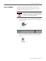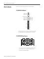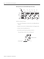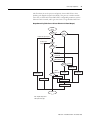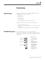
1
POINT I/O and ArmorPOINT I/O
DeviceLogix Modules
User Manual
(Catalog Numbers 1734-8CFGDLX,
1738-8CFGDLXM8, 1738-8CFGDLXM12, 1738-8CFGDLXM23)
Important User Information
Solid state equipment has operational characteristics differing from those of electromechanical equipment. Safety Guidelines for the
Application, Installation and Maintenance of Solid State Controls (publication SGI-1.1 available from your local Rockwell Automation sales
office or online at http://literature.rockwellautomation.com) describes some important differences between solid state equipment and hardwired electromechanical devices. Because of this difference, and also because of the wide variety of uses for solid state equipment, all
persons responsible for applying this equipment must satisfy themselves that each intended application of this equipment is acceptable.
In no event will Rockwell Automation, Inc. be responsible or liable for indirect or consequential damages resulting from the use or
application of this equipment.
The examples and diagrams in this manual are included solely for illustrative purposes. Because of the many variables and requirements
associated with any particular installation, Rockwell Automation, Inc. cannot assume responsibility or liability for actual use based on the
examples and diagrams.
No patent liability is assumed by Rockwell Automation, Inc. with respect to use of information, circuits, equipment, or software described in
this manual.
Reproduction of the contents of this manual, in whole or in part, without written permission of Rockwell Automation, Inc., is prohibited.
Throughout this manual, when necessary, we use notes to make you aware of safety considerations.
WARNING
IMPORTANT
ATTENTION
Identifies information about practices or circumstances that can cause an explosion in a
hazardous environment, which may lead to personal injury or death, property damage, or
economic loss.
Identifies information that is critical for successful application and understanding of the product.
Identifies information about practices or circumstances that can lead to personal injury or death,
property damage, or economic loss. Attentions help you identify a hazard, avoid a hazard, and
recognize the consequence
SHOCK HAZARD
Labels may be on or inside the equipment, for example, a drive or motor, to alert people that
dangerous voltage may be present.
BURN HAZARD
Labels may be on or inside the equipment, for example, a drive or motor, to alert people that
surfaces may reach dangerous temperatures.
Allen-Bradley, ArmorPOINT I/O, POINT I/O, POINTBus, Rockwell Automation, RSLogix, RSNetWorx, RSNetWorx for DeviceNet, and TechConnect are trademarks of Rockwell Automation, Inc.
Trademarks not belonging to Rockwell Automation are property of their respective companies.
Publication 1734-UM015A-EN-E - November 2009
Table of Contents
Preface
Purpose of This Manual. . . . . . . . . . . . . . . . . . . . . . . . . . . . . . . . . . . . . . 5
Who Should Use This Manual. . . . . . . . . . . . . . . . . . . . . . . . . . . . . . . . . 6
Related Publications . . . . . . . . . . . . . . . . . . . . . . . . . . . . . . . . . . . . . . . . . 6
Chapter 1
Introduction
About This Chapter . . . . . . . . . . . . . . . . . . . . . . . . . . . . . . . . . . . . . . . . . 9
About the Modules. . . . . . . . . . . . . . . . . . . . . . . . . . . . . . . . . . . . . . . . . . 9
1734-8CFGDLX . . . . . . . . . . . . . . . . . . . . . . . . . . . . . . . . . . . . . . . 10
1738-8CFGDLXM8, 1738-8CFGDLXM12, and
1738-8CFGDLXM23 . . . . . . . . . . . . . . . . . . . . . . . . . . . . . . . . . . . 10
Modes of Usage . . . . . . . . . . . . . . . . . . . . . . . . . . . . . . . . . . . . . . . . . . . 10
Standard POINT I/O Module . . . . . . . . . . . . . . . . . . . . . . . . . . . . 10
Stand Alone DeviceLogix . . . . . . . . . . . . . . . . . . . . . . . . . . . . . . . . 11
Peer Enabled POINT I/O . . . . . . . . . . . . . . . . . . . . . . . . . . . . . . . 11
Quick Start - Prepare the Modules to work on DeviceNet . . . . . . . . . 12
Quick Start - Prepare the Modules to work on EtherNet/IP and
ControlNet . . . . . . . . . . . . . . . . . . . . . . . . . . . . . . . . . . . . . . . . . . . . . . . 13
Chapter 2
Install POINT I/O DeviceLogix
Modules
About This Chapter . . . . . . . . . . . . . . . . . . . . . . . . . . . . . . . . . . . . . . . . 15
Install the Mounting Base Assembly . . . . . . . . . . . . . . . . . . . . . . . . . . . 17
Install an I/O Module . . . . . . . . . . . . . . . . . . . . . . . . . . . . . . . . . . . . . . 19
Install the Removable Terminal Block . . . . . . . . . . . . . . . . . . . . . . . . . 21
Remove a 1734-TB or 1734-TBS Base . . . . . . . . . . . . . . . . . . . . . . . . . 22
Remove a 1734-TOP or 1734-TOPS Base . . . . . . . . . . . . . . . . . . . . . . 23
Wire the Modules . . . . . . . . . . . . . . . . . . . . . . . . . . . . . . . . . . . . . . . . . . 24
1734-8CFGDLX I/O Module . . . . . . . . . . . . . . . . . . . . . . . . . . . . 24
1734-8CFGDLX Wiring Diagram . . . . . . . . . . . . . . . . . . . . . . . . . 24
System and Power Considerations . . . . . . . . . . . . . . . . . . . . . . . . . 25
Chapter 3
Install ArmorPOINT I/O
DeviceLogix Modules
1
About This Chapter . . . . . . . . . . . . . . . . . . . . . . . . . . . . . . . . . . . . . . . . 27
Install the Mounting Base . . . . . . . . . . . . . . . . . . . . . . . . . . . . . . . . . . . 27
Install the Module . . . . . . . . . . . . . . . . . . . . . . . . . . . . . . . . . . . . . . . . . 29
Remove the Module from the Mounting Base. . . . . . . . . . . . . . . . 30
Wire the Modules . . . . . . . . . . . . . . . . . . . . . . . . . . . . . . . . . . . . . . . . . . 30
1738-8CFGDLXM8 I/O Module . . . . . . . . . . . . . . . . . . . . . . . . . 30
1738-8CFGDLXM12 I/O Module . . . . . . . . . . . . . . . . . . . . . . . . 31
1738-8CFGDLXM23 I/O Module . . . . . . . . . . . . . . . . . . . . . . . . 32
Publication 1734-UM015A-EN-E - November 2009
2
Table of Contents
Chapter 4
DeviceLogix for POINT I/O and
ArmorPOINT I/O on DeviceNet
About This Chapter . . . . . . . . . . . . . . . . . . . . . . . . . . . . . . . . . . . . . . . . 33
Offline Configuration using RSNetworx for DeviceNet . . . . . . . . . . . 33
Example: Build the Backplane . . . . . . . . . . . . . . . . . . . . . . . . . . . . 34
Online Configuration using RSNetWorx for DeviceNet. . . . . . . . . . . 36
I/O Data Assembly Maps . . . . . . . . . . . . . . . . . . . . . . . . . . . . . . . . . . . 39
Chapter 5
DeviceLogix for POINT I/O and
ArmorPOINT I/O on
Ethernet/ControlNet
About This Chapter . . . . . . . . . . . . . . . . . . . . . . . . . . . . . . . . . . . . . . . . 43
Add a POINT I/O DeviceLogix Module to RSLogix 5000 . . . . . . . . 43
I/O Tags . . . . . . . . . . . . . . . . . . . . . . . . . . . . . . . . . . . . . . . . . . . . . 46
Launch RSNetworx for DeviceNet to Configure the Module. . . . . . . 47
Chapter 6
Configuring POINT I/O and
ArmorPOINT I/O DeviceLogix
modules using RSNetworx for
DeviceNet
About This Chapter . . . . . . . . . . . . . . . . . . . . . . . . . . . . . . . . . . . . . . . . 49
Configure the Module using the Configuration tab . . . . . . . . . . . . . . . 49
Parameters on the Parameters tab. . . . . . . . . . . . . . . . . . . . . . . . . . 53
Configure Peer Communication . . . . . . . . . . . . . . . . . . . . . . . . . . . . . . 54
Set Up Peer Communication Parameters . . . . . . . . . . . . . . . . . . . . 55
Produce Data Without Using a Master . . . . . . . . . . . . . . . . . . . . . . . . . 58
Start the Function Block Editor . . . . . . . . . . . . . . . . . . . . . . . . . . . . . . 61
Chapter 7
DeviceLogix Capabilities
Publication 1734-UM015A-EN-E - November 2009
About This Chapter . . . . . . . . . . . . . . . . . . . . . . . . . . . . . . . . . . . . . . . . 63
Function Block Instructions . . . . . . . . . . . . . . . . . . . . . . . . . . . . . . . . . 63
Process Category . . . . . . . . . . . . . . . . . . . . . . . . . . . . . . . . . . . . . . . 63
Filter Category . . . . . . . . . . . . . . . . . . . . . . . . . . . . . . . . . . . . . . . . . 64
Select Limit Category. . . . . . . . . . . . . . . . . . . . . . . . . . . . . . . . . . . . 64
Statistical Category . . . . . . . . . . . . . . . . . . . . . . . . . . . . . . . . . . . . . . 65
Timer/Counter Category. . . . . . . . . . . . . . . . . . . . . . . . . . . . . . . . . 65
Comparison Category . . . . . . . . . . . . . . . . . . . . . . . . . . . . . . . . . . . 66
Compute Category . . . . . . . . . . . . . . . . . . . . . . . . . . . . . . . . . . . . . . 67
Move/Logical Category. . . . . . . . . . . . . . . . . . . . . . . . . . . . . . . . . . 68
Logic Execution Time . . . . . . . . . . . . . . . . . . . . . . . . . . . . . . . . . . . 70
Digital Inputs to Function Blocks. . . . . . . . . . . . . . . . . . . . . . . . . . 71
Analog Inputs to Function Blocks . . . . . . . . . . . . . . . . . . . . . . . . . 73
Digital Outputs from Function Blocks. . . . . . . . . . . . . . . . . . . . . . 74
Analog Outputs from Function Blocks . . . . . . . . . . . . . . . . . . . . . 76
Enable Line feature . . . . . . . . . . . . . . . . . . . . . . . . . . . . . . . . . . . . . . . . 77
Offline and Online Editing . . . . . . . . . . . . . . . . . . . . . . . . . . . . . . . . . . 78
Enable/Disable Logic . . . . . . . . . . . . . . . . . . . . . . . . . . . . . . . . . . . . . . 79
Logic Enable On . . . . . . . . . . . . . . . . . . . . . . . . . . . . . . . . . . . . . . . 79
Logic Enable Off . . . . . . . . . . . . . . . . . . . . . . . . . . . . . . . . . . . . . . . 79
Dependent Mode . . . . . . . . . . . . . . . . . . . . . . . . . . . . . . . . . . . . . . . 79
Messaging . . . . . . . . . . . . . . . . . . . . . . . . . . . . . . . . . . . . . . . . . . . . . . . . 80
Table of Contents
3
Chapter 8
Troubleshooting
About This Chapter . . . . . . . . . . . . . . . . . . . . . . . . . . . . . . . . . . . . . . . . 83
About Module Diagnostics . . . . . . . . . . . . . . . . . . . . . . . . . . . . . . . . . . 83
Status Indicators of POINT I/O Module . . . . . . . . . . . . . . . . . . . . . . 84
1734-8CFGDLX Module . . . . . . . . . . . . . . . . . . . . . . . . . . . . . . . . 84
Status Indicators of ArmorPOINT I/O Modules . . . . . . . . . . . . . . . . 86
1738-8CFGDLXM8, 1738-8CFGDLXM12, and
1738-8CFGDLXM23 . . . . . . . . . . . . . . . . . . . . . . . . . . . . . . . . . . . 86
Troubleshooting Scenarios . . . . . . . . . . . . . . . . . . . . . . . . . . . . . . . . . . 88
Peer connection is not working. . . . . . . . . . . . . . . . . . . . . . . . . . . . 88
Configuration or DeviceLogix program cannot be
downloaded to the module . . . . . . . . . . . . . . . . . . . . . . . . . . . . . . . 89
Module’s DeviceLogix program exits the Run mode
unexpectedly. . . . . . . . . . . . . . . . . . . . . . . . . . . . . . . . . . . . . . . . . . . 90
Appendix A
Peer Data Maps
About This Appendix . . . . . . . . . . . . . . . . . . . . . . . . . . . . . . . . . . . . . . 91
Peer I/O Sizes . . . . . . . . . . . . . . . . . . . . . . . . . . . . . . . . . . . . . . . . . . . . 91
Digital Input Modules . . . . . . . . . . . . . . . . . . . . . . . . . . . . . . . . . . . 91
Analog and Specialty Input Modules . . . . . . . . . . . . . . . . . . . . . . . 92
Peer Data Maps . . . . . . . . . . . . . . . . . . . . . . . . . . . . . . . . . . . . . . . . . . . 93
2-Point Digital Input Modules . . . . . . . . . . . . . . . . . . . . . . . . . . . . 94
4-Point Digital Input Modules . . . . . . . . . . . . . . . . . . . . . . . . . . . . 94
4-Point Digital Input with Diagnostics Modules . . . . . . . . . . . . . . 95
8-Point Digital Input Modules . . . . . . . . . . . . . . . . . . . . . . . . . . . . 95
8-Point Configurable Modules . . . . . . . . . . . . . . . . . . . . . . . . . . . . 96
16-Point Digital Input Module . . . . . . . . . . . . . . . . . . . . . . . . . . . . 96
8-Point Digital Input Modules with DeviceLogix . . . . . . . . . . . . . 97
2-Point Analog Input Modules and RTD (Resistant
Temperature Device) . . . . . . . . . . . . . . . . . . . . . . . . . . . . . . . . . . . . 98
4-Point Analog Input Modules . . . . . . . . . . . . . . . . . . . . . . . . . . . . 99
8-Point Analog Input Modules . . . . . . . . . . . . . . . . . . . . . . . . . . . 100
2-Point Thermocouple Input Modules. . . . . . . . . . . . . . . . . . . . . 102
Very High Speed Counter Input Modules . . . . . . . . . . . . . . . . . . 103
Encoder/Counter Input Modules. . . . . . . . . . . . . . . . . . . . . . . . . 105
Synchronous Serial Interface Modules . . . . . . . . . . . . . . . . . . . . . 105
RS232 and RS485 Interface Module . . . . . . . . . . . . . . . . . . . . . . . 106
Publication 1734-UM015A-EN-E - November 2009
4
Table of Contents
Notes:
Publication 1734-UM015A-EN-E - November 2009
Preface
Purpose of This Manual
This manual describes how to install, configure, and troubleshoot your
POINT I/O DeviceLogix and ArmorPOINT I/O DeviceLogix modules.
POINT I/O and ArmorPOINT I/O modules can be used in EtherNet/IP,
DeviceNet, and ControlNet systems. As such, you may need to refer to other
publications in addition to this one.
When using POINT I/O DeviceLogix modules with a communication
adapter, use this manual in conjunction with the user manual for the adapter
you are using as shown in the table.
When Using POINT I/O
Modules on This Network
Refer to
Publication for
Catalog No.
Publication No.
DeviceNet network
DeviceNet adapter
1734-ADN
1734-ADNX
1734-UM002
ControlNet network
ControlNet adapter
1734-ACNR
1734-UM008
EtherNet/IP network
EtherNet/IP adapter
1734-AENT
1734-UM011
POINT I/O DeviceLogix modules are not compatible with the PROFIBUS
adapter.
When using ArmorPOINT I/O DeviceLogix modules with a communication
adapter, use this manual in conjunction with the user manual for the adapter
you are using as shown in the table.
When Using ArmorPOINT
I/O Modules on This
Network
Refer to
Publication for
Catalog No.
Publication No.
DeviceNet network
DeviceNet adapter
1738-ADN
1738-ADNX
1738-UM001
ControlNet network
ControlNet adapter
1738-ACNR
1738-IN016
EtherNet/IP network
EtherNet/IP adapter
1738-AENT
1738-AENTR
1738-IN017
1738-IN028
ArmorPOINT I/O DeviceLogix modules are not compatible with the
PROFIBUS adapter.
The modules in this manual are DeviceNet-ready. Each module can exist on
the DeviceNet network as one of the following:
• An individual node
• With an adapter (catalog number 1734-ADN or 1734-ADNX) as a
single node
For applications using these modules in a network with a 1734-PDN
DeviceNet Communication Interface, or a 1734D-xx POINTBlock I/O
module, this user manual is the primary documentation.
5
Publication 1734-UM015A-EN-E - November 2009
6
Preface
Who Should Use This
Manual
This manual is intended for qualified personnel. You should know how to do
the following:
• Use RSNetWorx software or similar configuration software to set up
and calibrate these modules.
• Download and use electronic data sheet (EDS) files.
In addition, you should be familiar with RSLogix 5000 and CIP Network
terminology. If you do not, refer to your software documentation or online
help before attempting to use these modules.
Related Publications
Refer to this table for a list of related POINT I/O products and
documentation. The publications are available from
http://literature.rockwellautomation.com/. For specification and safety
certification information, refer to the installation instructions.
Resource
Description
POINT I/O DeviceLogix Module
POINT I/O Module with 8 Configurable 24V DC Points and
DeviceLogix Installation Instructions, publication 1734-IN039
Provides installation information and wiring diagrams for
1734-8CFGDLX modules.
Communication Devices
ControlNet Adapter Installation Instructions,
publication 1734-IN582
Provides installation information about 1734-ACNR adapters.
ControlNet Adapter User Manual, publication 1734-UM008
Describes how to use 1734-ACNR adapters.
DeviceNet Communication Interface Module Installation
Instructions, publication 1734-IN057
Provides installation information about 1734-PDN modules.
DeviceNet Adapter Installation Instructions, publication 1734-IN026 Provides installation information about 1734-ADN and 1734-ADNX
adapters.
DeviceNet Adapter User Manual, publication 1734-UM002
Describes how to use 1734-ADN and 1734-ADNX adapters.
RSNetworx for DeviceNet Getting Results Guide, publication
DRNET-GR001
Describes how to install and navigate the RSNetWorx for
DeviceNet software.
EtherNet/IP Adapter Installation Instructions,
publication 1734-IN590
Provides installation information about 1734-AENT adapters.
EtherNet/IP Adapter User Manual, publication 1734-UM011
Describes how to use 1734-AENT adapters.
Power Supplies, Wiring Base Assemblies, Miscellaneous
Field Potential Distributor Installation Instructions,
publication 1734-IN059
Provides installation information about 1734-FPD distributors.
POINT I/O 24V dc Expansion Power Supply Installation Instructions,
publication 1734-IN058
Provides installation information about 1734-EP24DC power
supplies.
POINT I/O 120/240V ac Expansion Power Supply Installation
Instructions, publication 1734-IN017
Provides installation information about 1734-EPAC power supplies.
POINT I/O Common Terminal Module Installation Instructions,
publication 1734-IN024
Provides installation information about 1734-CTM modules.
Publication 1734-UM015A-EN-E - November 2009
Preface
Resource
Description
POINT I/O Voltage Terminal Module Installation Instructions,
publication 1734-IN024
Provides installation information about 1734-VTM modules.
POINT I/O Wiring Base Assembly Installation Instructions,
publication 1734-IN511
Provides installation information about 1734-TB and 1734-TBS
assemblies.
POINT I/O Wiring Base Assembly Installation Instructions,
publication 1734-IN013
Provides installation information about 1734-TB3 and 1734-TB3S
assemblies.
POINT I/O One-piece Wiring Base Assembly Installation
Instructions, publication 1734-IN028
Provides installation information about 1734-TOP, 1734-TOPS,
1734-TOP3 and 1734-TOP3S assemblies.
7
Refer to this table for a list of related ArmorPOINT I/O products and
documentation. The publications are available from
http://literature.rockwellautomation.com/. For specification and safety
certification information, refer to the installation instructions.
Resource
Description
ArmorPOINT I/O DeviceLogix Module
ArmorPOINT I/O Modules with 8 Configurable 24V DC Points Wiring Provides wiring diagrams for 1738-8CFGDLXM8,
Diagrams, publication 1738-WD009
1738-8CFGDLXM12, and 1738-8CFGDLXM23.
ArmorPOINT Module with Configurable 24V DC Points and
DeviceLogix Installation Instructions, publication 1738-IN027
Provides installation information about 1738-8CFGDLXM8,
1738-8CFGDLXM12, and 1738-8CFGDLXM23.
Communication Devices
ArmorPOINT ControlNet Adapter, Series A Installation Instructions,
publication 1738-IN016
Provides installation information about 1738-ACNR adapters.
ArmorPOINT I/O DeviceNet Adapter Installation Instructions,
publication 1738-IN014
Provides installation information about 1738-ADN and 1738-ADNX
adapters.
ArmorPOINT I/O DeviceNet Adapter User Manual, publication
1738-UM001
Describes how to use 1738-ADN and 1738-ADNX adapters.
ArmorPOINT EtherNet/IP Adapter, Series A Installation Instructions, Provides installation information about 1738-AENT adapters.
publication 1738-IN017
ArmorPOINT I/O 2-Port EtherNet/IP Adapter, Series A Installation
Instructions, publication 1738-IN028
Provides installation information about 1738-AENTR adapters.
Power Supplies, Wiring Base Assemblies, Miscellaneous
ArmorPOINT I/O Field Potential Distributor, Series A Installation
Instructions, publication 1738-IN019
Provides installation information about 1738-FPD distributors.
ArmorPOINT I/O 24V dc Expansion Power Supply, Series A
Installation Instructions, publication 1738-IN020
Provides installation information about 1738-EP24DC power
supplies.
Publication 1734-UM015A-EN-E - November 2009
8
Preface
Notes:
Publication 1734-UM015A-EN-E - November 2009
Chapter
1
Introduction
About This Chapter
This chapter introduces POINT I/O and ArmorPOINT I/O configurable
modules with DeviceLogix capability.
• About the Modules
• Quick Start - Prepare the Modules to work on DeviceNet
• Quick Start - Prepare the Modules to work on EtherNet/IP and
ControlNet
About the Modules
The POINT I/O and ArmorPOINT I/O modules work with EtherNet/IP,
DeviceNet and ControlNet network adapters. Each module has eight 24V DC
I/O points that self-configure to be inputs or outputs. Inputs are IEC Type 3
and outputs are self-protecting 0.5 A outputs.
The firmware in these modules uses Version 3 of the DeviceLogix master
library. The modules can execute 144 DeviceLogix function blocks in 3 ms.
Smaller programs that contain fewer than 40 function blocks can be executed
in 1 ms.
Each module produces 20 bytes of data including I/O state (eight bits), eight
user-defined bits, and eight user-defined words of analog data to be consumed
by processors or other DeviceLogix modules. Each module consumes 20 bytes
of data to set the I/O state (eight bits), eight user-defined control bits, and
eight user-defined words of analog data. It is also possible to consume the data
from up to eight other peers.
This table lists 1734 and 1738 configurable I/O modules with DeviceLogix.
9
Module Description
Cat. No.
POINT I/O module with 8 configurable 24V DC I/O points
and DeviceLogix capabilities
1734-8CFGDLX
ArmorPOINT I/O module with 8 configurable 24V DC M8
connectors and DeviceLogix
1738-8CFGDLXM8
ArmorPOINT I/O module with 8 configurable 24V DC M12
connectors and DeviceLogix
1738-8CFGDLXM12
ArmorPOINT I/O module with 1 configurable 24V DC M23
connector and DeviceLogix
1738-8CFGDLXM23
Publication 1734-UM015A-EN-E - November 2009
10
Introduction
1734-8CFGDLX
This module is an 8-point 24V DC I/O module with 8 self-configuring points
and DeviceLogix capabilities. Each of the I/O points can be either a DC input
or output. The module supports removal and insertion under power,
auto-address, and auto-baud in compliance with the POINTBus backplane.
1738-8CFGDLXM8, 1738-8CFGDLXM12, and 1738-8CFGDLXM23
The ArmorPOINT I/O family consists of modular I/O modules. The sealed
IP67 housing of these modules requires no enclosure. Note that
environmental requirements other than IP67 may require an additional
appropriate housing. I/O connectors are sealed M8 (pico), M12 (micro) or
M23 styles. The mounting base ships with the module.
Modes of Usage
The module can be used in one of the following modes:
• as a standard POINT I/O module,
• in a stand alone DeviceLogix program where it controls its own I/O,
and
• in network applications with or without the peer exchange of data.
Standard POINT I/O Module
The module can simply be used as an 8-point configurable POINT I/O
module. It uses ODVA pre-defined Produce and Consume assemblies. Default
settings help to facilitate quick setup right out-of-the-box. It is CIP network
independent and it can run on DeviceNet, EtherNet/IP or ControlNet when
used in conjunction with an adapter.
Publication 1734-UM015A-EN-E - November 2009
Introduction
11
Stand Alone DeviceLogix
If DeviceLogix is enabled (programmed), then the module becomes the owner
of its outputs. The DeviceLogix program reads inputs and controls the
onboard outputs.
• The produced assembly may be shared with a controller if a connection
exists.
• As the owner of its local outputs, the module may run without an
external controller.
An external controller, which is the owner of the connection to the module,
can influence the module’s logic via a consume assembly – both digital and
analog data. Configuration of the module is performed via RSNetWorx for
DeviceNet. When used on ControlNet or EtherNet/IP, the tool bridges
through the adapter to directly communicate with the DeviceLogix module on
the POINT I/O backplane.
Peer Enabled POINT I/O
The POINT I/O DeviceLogix module can “listen in” on data connections to
other POINT I/O modules on the backplane. This data can be used in the
DeviceLogix program to control the outputs. It can consume data from 8
different peers. The data from each peer can be up to 24 bytes long. The data
can be digital, analog (16-bit), or a mixture. The module supports the “Auto
Produce” parameter to produce I/O data automatically without the need for a
master. It will also produce and consume network data. Configuration of peer
data is performed via RSNetWorx.
See Chapter 6, Configuring POINT I/O and ArmorPOINT I/O DeviceLogix
modules using RSNetworx for DeviceNet.
Publication 1734-UM015A-EN-E - November 2009
12
Introduction
Quick Start - Prepare the
Modules to work on
DeviceNet
Mount the Module
For POINT I/O, see Chapter 2.
For ArmorPOINT I/O, see Chapter 3.
Wire the Module
For POINT I/O, see Chapter 2.
For ArmorPOINT I/O, see Chapter 3.
Configure DeviceNet Network and
Scanner
See Chapter 4.
Configure the Module using
RSNetWorx for DeviceNet
See Chapter 6.
Write the DeviceLogix Program
See Chapter 7.
Publication 1734-UM015A-EN-E - November 2009
Introduction
Quick Start - Prepare the
Modules to work on
EtherNet/IP and ControlNet
13
Mount the Module
For POINT I/O, see Chapter 2.
For ArmorPOINT I/O, see Chapter 3.
Wire the Module
For POINT I/O, see Chapter 2.
For ArmorPOINT I/O, see Chapter 3.
Add Module to RSLogix 5000
See Chapter 5.
Write the DeviceLogix Program in
RSNetworx for DeviceNet
See Chapter 7.
Publication 1734-UM015A-EN-E - November 2009
14
Introduction
Notes:
Publication 1734-UM015A-EN-E - November 2009
Chapter
2
Install POINT I/O DeviceLogix Modules
If you are using ArmorPOINT I/O modules
(1738-8CFGDLXM8/M12/M23), go to Chapter 3, Install ArmorPOINT I/O
DeviceLogix Modules.
About This Chapter
Read this chapter for installation and wiring information including how to
complete the following:
• Install the Mounting Base Assembly
• Install an I/O Module
• Install the Removable Terminal Block
• Remove a 1734-TB or 1734-TBS Base
• Wire the Modules
ATTENTION
Environment and Enclosure
This equipment is intended for use in a Pollution Degree 2
industrial environment, in overvoltage Category II applications
(as defined in IEC publication 60664-1), at altitudes up to 2000 m
(6561 ft) without derating.
This equipment is considered Group 1, Class A industrial
equipment according to IEC/CISPR 11. Without appropriate
precautions, there may be potential difficulties ensuring
electromagnetic compatibility in other environments due to
conducted as well as radiated disturbance.
This equipment is supplied as open-type equipment. It must be
mounted within an enclosure that is suitably designed for those
specific environmental conditions that will be present and
appropriately designed to prevent personal injury resulting from
accessibility to live parts. The interior of the enclosure must be
accessible only by the use of a tool. Subsequent sections of this
publication may contain additional information regarding specific
enclosure type ratings that are required to comply with certain
product safety certifications.
See NEMA Standards 250 and IEC 60529, as applicable, for
explanations of the degrees of protection provided by different
types of enclosure. Also, see the appropriate sections in this
publication, as well as the Allen-Bradley publication 1770-4.1
(Industrial Automation Wiring and Grounding Guidelines), for
additional installation requirements pertaining to this equipment.
15
Publication 1734-UM015A-EN-E - November 2009
16
Install POINT I/O DeviceLogix Modules
ATTENTION
WARNING
ATTENTION
POINT I/O is grounded through the DIN rail to chassis ground.
Use zinc-plated, yellow-chromated steel DIN rail to assure proper
grounding. The use of DIN rail materials (for example, aluminum
or plastic) that can corrode, oxidize, or are poor conductors, can
result in improper or intermittent grounding.
Secure DIN rail to mounting surface approximately every 200
mm (7.8 in.).
EXPLOSION HAZARD
• Do not disconnect equipment unless power has been
removed or the area is known to be nonhazardous.
• Do not disconnect connections to this equipment unless
power has been removed or the area is known to be
nonhazardous. Secure any external connections that mate to
this equipment by using screws, sliding latches, threaded
connectors, or other means provided with this product.
• Substitution of components may impair suitability for Class I,
Division 2.
• If this product contains batteries, they must only be changed
in an area known to be nonhazardous.
Prevent Electrostatic Discharge
This equipment is sensitive to electrostatic discharge, which can
cause internal damage and affect normal operation. Follow these
guidelines when you handle this equipment:
•
•
•
•
•
•
Publication 1734-UM015A-EN-E - November 2009
Touch a grounded object to discharge potential static.
Wear an approved grounding wriststrap.
Do not touch connectors or pins on component boards.
Do not touch circuit components inside the equipment.
Use a static-safe workstation, if available.
Store the equipment in appropriate static-safe packaging when
not in use.
Install POINT I/O DeviceLogix Modules
Install the Mounting Base
Assembly
17
The 1734-8CFGDLX is compatible with 1734-TB, 1734-TBS, 1734-TOP, and
1734-TOPS wiring bases.
The 1734-TB or 1734-TBS wiring base assembly consists of a 1734-MB
mounting base and a 1734-RTB or 1734-RTBS removable terminal
block (RTB).
1734-TB or 1734-TBS wiring base
Module Locking
Mechanism
Slide-in Writable
Label
ule
od tus
MS
ta
ork
tw s
NeStatuE:
D
NO
4
5
0
6
1
7
2
3
Module Wiring
Diagram
Insertable I/O
Module
DIN Rail Locking
Screw (orange)
RTB Removal
Handle
Mechanical
Keying (orange)
Removable
Terminal Block
(RTB)
Interlocking Side
Pieces
Mounting Base
44713
The 1734-TOP and 1734-TOPS are one-piece terminal bases.
1734-TOP or 1734-TOPS wiring base
Module Locking
Mechanism
Slide-in
Writable Label
Module Wiring
Diagram
Insertable
I/O Module
DIN Rail Locking
Screw (orange)
Handle
Mechanical
Keying (orange)
Interlocking
Side Pieces
44714
1734-TOP or
1734-TOPS
One-piece
Terminal Base
with Screw or
Spring Clamp
Publication 1734-UM015A-EN-E - November 2009
18
Install POINT I/O DeviceLogix Modules
To install the mounting base assembly on the DIN rail, proceed as follows.
1. If you are using the 1734-TB or 1734-TBS mounting base, attach the
RTB to the mounting base.
Otherwise, skip to step 2.
Removable
Terminal Block
(RTB)
Mounting Base
44858
2. Position the mounting base (wiring base assembly) vertically above the
installed units, for example, adapter, power supply, or existing module.
3. Slide the mounting base down, allowing the interlocking side pieces to
engage the adjacent module, power supply, or adapter.
31586
4. Press firmly to seat the mounting base on the DIN rail until the base
snaps into place.
5. Use a small-bladed screwdriver to rotate the DIN-rail locking screw to
the horizontal position.
This locks the assembly to the DIN rail.
Publication 1734-UM015A-EN-E - November 2009
Install POINT I/O DeviceLogix Modules
Install an I/O Module
19
Install the module before or after base installation. Make sure that the
mounting base is correctly keyed before installing the module into the
mounting base. In addition, make sure the mounting base locking screw is
positioned horizontally referenced to the base.
WARNING
When you insert or remove the module while backplane power is
on, an electrical arc can occur. This could cause an explosion in
hazardous location installations. Be sure that power is removed
or the area is nonhazardous before proceeding.
1. Use a bladed screwdriver to rotate the keyswitch on the mounting base
clockwise until the number required for the type of module aligns with
the notch in the base.
Notch
44710
Position 1 is shown.
Module
Keyswitch Position
1734-8CFGDLX
1
2. Make certain the DIN-rail locking screw is in the horizontal position,
noting that you cannot insert the module if the locking mechanism is
unlocked.
44966
Publication 1734-UM015A-EN-E - November 2009
20
Install POINT I/O DeviceLogix Modules
M
St od
at u
us le
3
1
O 73
B 4
4E
2
1
0
2
S 4V
O ou DC
ut rc
pu e
t
N
S e
N ta tw
O t o
D us rk
E:
3. Insert the module straight down into the mounting base and press to
secure.
44967
4. Secure the module with the RTB removal handle (for 1734-TB or
1734-TBS bases) or handle (for 1734-TOP or 1734-TOPS bases).
Module
Handle
44859
Publication 1734-UM015A-EN-E - November 2009
Install POINT I/O DeviceLogix Modules
Install the Removable
Terminal Block
21
A removable terminal block (RTB) is supplied with your mounting base
assembly.
To remove, pull up on the RTB handle. This lets you remove and replace the
base when necessary without removing any of the wiring.
To re-insert the RTB, proceed as follows.
WARNING
When you connect or disconnect the RTB with field-side power
applied, an electrical arc can occur. This could cause an
explosion in hazardous location installations. Be sure to remove
power or that the area is nonhazardous before proceeding.
1. Insert the RTB end opposite the handle into the base unit.
This end has a curved section that engages with the mounting base.
44968
2. Rotate the terminal block into the mounting base until it locks itself in
place.
3. If an I/O module is installed, snap the RTB handle into place on the
module.
Publication 1734-UM015A-EN-E - November 2009
22
Install POINT I/O DeviceLogix Modules
Remove a 1734-TB or
1734-TBS Base
To remove a 1734-TB or 1734-TBS mounting base, do the following.
WARNING
When you insert or remove the module while backplane power
is on, an electrical arc can occur. This could cause an explosion
in hazardous location installations. Be sure to remove power or
that the area is nonhazardous before proceeding.
1. Unlatch the RTB handle on the I/O module.
2. Pull on the RTB handle to remove the RTB.
3. Press on the module lock on the top of the I/O module and pull the
I/O module out of the base.
4. Remove the I/O module to the right of the base you are removing,
noting that the interlocking portion of the base sits under the adjacent
module.
5. Use a small-bladed screwdriver to rotate the orange DIN-rail locking
screw on the mounting base to a vertical position.
6. This unlocks the mounting base from the DIN rail.
7. Lift the mounting base straight up to remove.
44969
Publication 1734-UM015A-EN-E - November 2009
Install POINT I/O DeviceLogix Modules
Remove a 1734-TOP or
1734-TOPS Base
23
To remove a wiring base from the DIN rail, you must remove the module
installed to the right of the base.
WARNING
If you connect or disconnect wiring while the field-side power
is on, an electrical arc can occur. This could cause an explosion
in hazardous location installations.
Be sure that power is removed or the area is nonhazardous
before proceeding.
1. Squeeze the module locking mechanism of the module to the right of
the base, pulling up to remove the module.
2. Use a small-bladed screwdriver to rotate the orange DIN-rail locking
screw on the mounting base to a vertical position.
This unlocks the mounting base from the DIN rail.
3. Slide the base up to release it from its mating units.
Publication 1734-UM015A-EN-E - November 2009
24
Install POINT I/O DeviceLogix Modules
Wire the Modules
This section provides wiring instructions for the modules.
1734-8CFGDLX I/O Module
Module Status
Module
Status
Network Status
Network
Status
NODE:
DeviceLogix Status
Status of I/O 0
Status of I/O 1
Status of I/O 2
Status of I/O 3
Device
Logix
Status
0
4
1
5
2
6
3
77
Status of I/O 4
Status of I/O 5
Status of I/O 6
Status of I/O 7
1734
8CFGDLX
I/O 0
I/O 1
I/O 2
I/O 3
I/O 4
I/O 5
I/O 6
I/O 7
44758
Note that voltage and current to the module is applied through the adapter,
the 1734-FPD module, or the 1734-EP24DC module. V = 10…28.8 V DC.
1734-8CFGDLX Wiring Diagram
Prox
Prox
Prox
I/O 0 I/O 1
I/O 2 I/O 3
I/O 4 I/O 5
Prox
I/O 6 I/O 7
V C
Load
Load
Load
Load
C
44687
If a connection to Common or the Supply Voltage is required for two- or
three- wire devices, then a 1734-CTM or 1734-VTM can be used.
Each I/O point is either Input or Output.
Publication 1734-UM015A-EN-E - November 2009
Install POINT I/O DeviceLogix Modules
Channel
25
Terminal Number
I/O
Common
Voltage
0
0
External(1)
External(2)
1
1
2
2
3
3
4
4
5
5
6
6
7
7
10/28.8 V DC is supplied through the internal power bus.
(1)
Common connections require an external connection, such as a 1734-CTM module.
(2)
Supply Voltage Connections require an external connection such as a 1734-VTM module.
System and Power Considerations
There are no power terminals on the POINT I/O DeviceLogix module. The
module gets its power from the Field Power Bus of the back plane. Depending
on your system and network topology, power can be applied through one of
the following:
•
•
•
•
•
•
1734-PDN (DeviceNet adapter)
1734-ADN or 1734-ADNX (DeviceNet adapter)
1734-ACNR (ControlNet adapter)
1734-AENT or 1734-AENTR (EtherNet/IP adapter)
1734-EP24DC (Expansion power supply)
1734-FPD (Field power distribution)
Publication 1734-UM015A-EN-E - November 2009
26
Install POINT I/O DeviceLogix Modules
Example of Logical Partitioning
ADN
Adapter
Status
DeviceNet
Status
PointBus
Status
1734-ADN
I
E
2
C
EP24DC
O
E
2
C
I
B
2
O
B
2
E
I
B
2
1734-EP24DC
System
Power
Status
Power
O
B
4
E
O
B
2
E
r
DeviceNet
Power
DeviceNet
Power
0 1
0 1
0 1
0 1
0 1
0 1
0 1
0 1
1
12V DC supply
24V DC supply
1734adn4
Similarly, field power and common (return) can be terminated in the POINT
I/O system by using the following modules:
• 1734-VTM (Voltage termination module)
• 1734-CTM (Common termination module)
1734-VTM
1734-CTM
0
0
1
1
1734
CTM
1734
VTM
Voltage Out
Voltage Out
Common
Common
Voltage Out
Voltage Out
Common
Common
Voltage Out
Voltage Out
Common
Common
Voltage Out
Voltage Out
Common
Common
Voltage Out = 0…7
Publication 1734-UM015A-EN-E - November 2009
Common = 0…7
43929
Chapter
3
Install ArmorPOINT I/O DeviceLogix Modules
If you are using POINT I/O modules (1734-8CFGDLX), go to Chapter 2,
Install POINT I/O DeviceLogix Modules.
About This Chapter
Read this chapter for information about how to install ArmorPOINT I/O
modules to include the following:
• Install the Mounting Base
• Install the Module
• Wire the Modules
• Remove the Modules
ATTENTION
Install the Mounting Base
This equipment is considered Group 1, Class A industrial
equipment according to IEC/CISPR Publication 11. Without
appropriate precautions, there may be potential difficulties
ensuring electromagnetic compatibility in other environments
due to conducted as well as radiated disturbance.
Mount the I/O base on a wall or panel, using the screw holes provided in the
base.
IMPORTANT
ATTENTION
ATTENTION
The ArmorPOINT I/O module must be mounted on a grounded
metal mounting plate or other conductive surface.
Make sure all connectors and caps are securely tightened to
properly seal the connections against leaks and maintain IP
enclosure type requirements.
To comply with the CE Low Voltage Directive (LVD), all
connected I/O must be powered from a source compliant with
the following:
Safety Extra Low Voltage (SELV) or Protected Extra Low Voltage
(PELV).
27
Publication 1734-UM015A-EN-E - November 2009
28
Install ArmorPOINT I/O DeviceLogix Modules
Mounting illustration for the ArmorPOINT adapter with I/O bases
Adapter
Adapter
47.2 mm
1.9 in
47.2 mm
1.9 in
50 mm
2.0 in
50 mm
2.0 in
50 mm
2.0 in
22 mm
0.87 in
22 mm
0.87 in
22 mm
0.87 in
50 mm
2.0 in
22 mm
0.87 in
50 mm
2.0 in
50 mm
2.0 in
102 mm
102
4.02
in mm
4.02 in
46 mm
1.81 in
46 mm
1.81 in
43769
Install the mounting as follows:
1. Lay out the required points as shown above in the drilling dimension
drawing.
2. Drill the necessary holes for M4 (#8) machine or self-tapping screws.
3. Mount the base using M4 (#8) screws.
4. Ground the system using the ground lug connection.
The ground lug connection is also a mounting hole.
Ground lug connection
Latching mechanism
Publication 1734-UM015A-EN-E - November 2009
43675
Install ArmorPOINT I/O DeviceLogix Modules
Install the Module
29
Follow the instructions to install the module.
1. Using a bladed screwdriver, rotate the keyswitch on the mounting base
clockwise until the number 1 aligns with the notch in the base.
Keyswitch
Set to position 1, for the
1738 24V DC modules
43675
2. Position the module vertically above the mounting base.
The module bridges two bases.
Module bridges two bases
A
DLX
B
H
1738-8CFGDLXM12 MOD
24V DC Out
NET
G
0
1738-8CFGDLXM12
shown
1
2
C
F
3
4
5
D
E
6
7
43771
3. Push the module down until it engages the latching mechanism.
You will hear a clicking sound when the module is properly engaged.
The locking mechanism locks the module to the base.
Publication 1734-UM015A-EN-E - November 2009
30
Install ArmorPOINT I/O DeviceLogix Modules
Remove the Module from the Mounting Base
Follow the instructions to remove the module from the mounting base.
1. Put a flat blade screwdriver into the slot of the orange latching
mechanism.
2. Push the screwdriver toward the I/O module to disengage the latch.
The module lifts up off the base.
3. Pull the module off the base.
Wire the Modules
This section provides wiring instructions for the modules.
ATTENTION
Make sure all connectors and caps are securely tightened to
properly seal the connections against leaks and maintain IP
enclosure type requirements.
1738-8CFGDLXM8 I/O Module
1738-8CFGDLXM8
24V DC
Connector M8-B
0
1
2
MOD
NET
3 DLX
Connector M8-A
Connector M8-D
Connector M8-C
0
1
4
5
2
3
Connector M8-E
LED indicators
4
6
Connector M8-G
7
5
6
7
43683
Connector M8-F
Connector M8-H
Publication 1734-UM015A-EN-E - November 2009
Install ArmorPOINT I/O DeviceLogix Modules
31
1738-8CFGDLXM8 Wiring Diagram
43583
(view into connector)
Pin 1 - 24V DC
Pin 3 - Common
Pin 4 - I/O 0 (M8-A)
I/O 1 (M8-B)
I/O 2 (M8-C)
I/O 3 (M8-D)
I/O 4 (M8-E)
I/O 5 (M8-F)
I/O 6 (M8-G)
I/O 7 (M8-H)
1738-8CFGDLXM12 I/O Module
H
A
Connectors M12-E...H
Connectors M12-A...D
DLX
B
1738-8CFGDLXM12 MOD
24V DC Out
NET
G
0
1
2
C
F
LED indicators
3
4
5
D
E
6
7
44355
1738-8CFGDLXM12 Wiring Diagram
43664
(view into connector)
Pin 1 - 24V DC
Pin 2 - Not used
Pin 3 - Common
Pin 4 - I/O 0 (M12-A)
I/O 1 (M12-B)
I/O 2 (M12-C)
I/O 3 (M12-D)
I/O 4 (M12-E)
I/O 5 (M12-F)
I/O 6 (M12-G)
I/O 7 (M12-H)
Pin 5 - Not used
Publication 1734-UM015A-EN-E - November 2009
32
Install ArmorPOINT I/O DeviceLogix Modules
1738-8CFGDLXM23 I/O Module
1738-8CFGDLXM23
24V DC In
M23 connector
MOD
NET
DLX
0
1
2
LED indicators
3
4
5
6
7
44353
1738-8CFGDLXM23 Wiring Diagram
43681
(view into connector)
Pin 1 - I/O 0
Pin 2 - I/O 1
Pin 3 - I/O 2
Pin 4 - I/O 3
Pin 5 - I/O 4
Pin 6 - I/O 5
Pin 7 - I/O 6
Pin 8 - I/O 7
Pin 9 - Return (Com)
Pin 10 - Return (Com)
Pin 11 - 24V DC
Pin 12 - Chassis
The ArmorPOINT I/O DeviceLogix module gets its power from the Field
Power Bus of the backplane. Depending on your system and network
topology, power can be applied through one of the following:
• 1738-ADN12 or 1738-ADN18, 1738-ADN18P, 1738-ADNX
(DeviceNet adapter)
• 1738-ACNR (ControlNet adapter)
• 1738-AENT or 1738-AENTR (EtherNet/IP adapter)
• 1738-EP24DC (Expansion power supply)
• 1738-FPD (Field power distribution)
Publication 1734-UM015A-EN-E - November 2009
Chapter
4
DeviceLogix for POINT I/O and ArmorPOINT
I/O on DeviceNet
About This Chapter
This chapter provides information on the following:
• Offline Configuration using RSNetworx for DeviceNet
• Online Configuration using RSNetWorx for DeviceNet
• I/O Data Assembly Maps
Offline Configuration using
RSNetworx for DeviceNet
This section is not a substitute for RSNetworx or DeviceNet scanner and
adapter publications. It is suggested that you have those publications available
while performing the procedures in this section See Related Publications for a
list of related publications.
This section describes the setup of a DeviceNet network using RSNetworx for
DeviceNet when the module is not connected to the network.
When configuring the module in the Offline mode, you must place all nodes
on the network in the View window manually. Use the Hardware tree to find
each module and place it into the View window. This can be done by
double-clicking the module or dragging it to the View window.
If using a POINT I/O or ArmorPOINT I/O DeviceNet adapter, make sure
you select Adapter for the main DeviceNet network, and Scanner for the
Pointbus backplane.
33
Publication 1734-UM015A-EN-E - November 2009
34
DeviceLogix for POINT I/O and ArmorPOINT I/O on DeviceNet
Example: Build the Backplane
This example shows you how to build the backplane. The following screen
shows the 1734-ADN Point I/O Scanner added.
Next, locate the I/O modules. In this example, the following modules will be
added:
• 1734-8CFGDLX POINT I/O DeviceLogix module
• 1734-IB8 POINT I/O DC Input module
• 1734-IE4C POINT I/O 4...20 mA Analog Input module
Publication 1734-UM015A-EN-E - November 2009
DeviceLogix for POINT I/O and ArmorPOINT I/O on DeviceNet
35
The digital modules can be found under the category, “General Purpose
Discrete I/O”, and the analog modules can be found under the “Rockwell
Automation miscellaneous” category.
The configuration of each module can now be edited from the Properties
dialog box of each module. For instructions on editing the configuration of the
DeviceLogix module, see Chapter 6.
Include all the I/O modules in the backplane to the Scanner’s scan list.
After configuration is complete, save your work in the DNT file. “DNT” is
the three-letter file name extension. One file contains all the configuration data
for all the modules on the network or backplane.
Remember that you need to go to the Online mode with RSNetWorx for
DeviceNet to download all the configuration data to the I/O modules and
scanners.
Publication 1734-UM015A-EN-E - November 2009
36
DeviceLogix for POINT I/O and ArmorPOINT I/O on DeviceNet
Online Configuration using
RSNetWorx for DeviceNet
To set up a DeviceNet network using RSNetWorx for DeviceNet when
connected to the network, do the following:
1. If you have a DNT file that has been configured, open the file in
RSNetWorx for DeviceNet. To do this, go to the Online mode by
pressing <F10>. You can also click Network > Online, or click the
Online button
.
RSLinx will start. If the Online path is not set in Network > Properties,
the Browse for network dialog box will appear.
2. Navigate to the DeviceNet network or DeviceNet subnet if configuring
the backplane.
The OK button will become available when you select a valid network.
RSNetWorx will automatically browse the network to discover all the
participants.
3. If there are any module identity issues, correct them before continuing.
4. Ensure that the configuration in the DNT file matches the
configuration in each node.
In this section, it is assumed that all the work was done in the Offline
mode and that the DNT file contains all the correct information.
Publication 1734-UM015A-EN-E - November 2009
DeviceLogix for POINT I/O and ArmorPOINT I/O on DeviceNet
37
To update all the modules in the most efficient way, click Network >
Download to Network on the menu bar.
5. Review the Message window for any errors.
The stored configuration (DNT file) and the configuration of all the
modules now match.
6. If any changes are made, be sure to download them to the module and
save them in the DNT file.
7. When in the Online mode, you can change the configuration of a
module by double-clicking its icon. You can also right-click the icon and
select Properties.
Publication 1734-UM015A-EN-E - November 2009
38
DeviceLogix for POINT I/O and ArmorPOINT I/O on DeviceNet
Familiarize yourself with all the tabs in the Properties window before
proceeding to Chapter 6 where you will learn how to configure the
DeviceLogix module.
Publication 1734-UM015A-EN-E - November 2009
DeviceLogix for POINT I/O and ArmorPOINT I/O on DeviceNet
I/O Data Assembly Maps
39
Read this section for information about how to communicate with your
module.
I/O messages are sent to (consumed) and received from (produced) the I/O
modules. These messages are mapped into the processor’s or scanner’s
memory. Each module produces 1, 8 or 20 bytes of input data based on which
produced assembly is selected. The default setup is 20 bytes.
It consumes 1, 8 or 20 bytes of I/O data (scanner Tx).
Default Data Map - Produced Assembly Instance 101
Message Size: 20 Bytes
Bit
7
6
5
4
3
2
1
0
Data [0]
Pt 07
Pt 06
Pt 05
Pt 04
Pt 03
Pt 02
Pt 01
Pt 00
Data [1]
PNB 07 PNB 06 PNB 05 PNB 04 PNB 03 PNB 02 PNB 01 PNB 00
Data [2]
Reserved
Data [3]
PM7
Data [4]
Produced Network Analog Word 0
PM6
PM5
PM4
PM3
PM2
Owned
LogicEn
PM1
PM0
Data [5]
Data [6]
Produced Network Analog Word 1
Data [7]
Data [8]
Produced Network Analog Word 2
Data [9]
Data [10] Produced Network Analog Word 3
Data [11]
Data [12] Produced Network Analog Word 4
Data [13]
Data [14] Produced Network Analog Word 5
Data [15]
Data [16] Produced Network Analog Word 6
Data [17]
Data [18] Produced Network Analog Word 7
Data [19]
Where:
• Pt = value of the I/O point,
• PNB = Produced Network Bit,
• PM = Peer Missing (a 1 indicates the absence of a configured peer)
• Owned = Owned by a master.
When set to 0, the module is producing data without a master.
When set to 1, the module is producing while being owned by a master.
• LogicEn = Logic Enabled (0 = logic disabled, 1 = logic enabled)
Publication 1734-UM015A-EN-E - November 2009
40
DeviceLogix for POINT I/O and ArmorPOINT I/O on DeviceNet
You can select other produced assemblies:
• Produced assembly instance 4 is the first byte of produced assembly
instance 101 (Data [0]).
• Produced assembly instance 111 is the first eight bytes of produced
assembly instance 101 (Data [0]…[7]).
Default Data Map - Consumed Assembly Instance 102
Message Size: 20 Bytes
Bit
7
6
5
4
3
2
1
0
Data [0]
Pt 07
Pt 06
Pt 05
Pt 04
Pt 03
Pt 02
Pt 01
Pt 00
Data [1]
CNB 07 CNB 06 CNB 05 CNB 04 CNB 03 CNB 02 CNB 01 CNB 00
Data [2]
Reserved
Data [3]
Data [4]
Consumed Network Analog Word 0
Data [5]
Data [6]
Consumed Network Analog Word 1
Data [7]
Data [8]
Consumed Network Analog Word 2
Data [9]
Data [10] Consumed Network Analog Word 3
Data [11]
Data [12] Consumed Network Analog Word 4
Data [13]
Data [14] Consumed Network Analog Word 5
Data [15]
Data [16] Consumed Network Analog Word 6
Data [17]
Data [18] Consumed Network Analog Word 7
Data [19]
Where: Pt = value to be applied to the output point, CNB = Consumed Network Bit
You can select other consumed assemblies:
• Consumed assembly instance 34 is the first byte of consumed assembly
instance 102 (Data [0]).
• Consumed assembly instance 112 is the first eight bytes of consumed
assembly instance 102 (Data [0]…[7]).
Publication 1734-UM015A-EN-E - November 2009
DeviceLogix for POINT I/O and ArmorPOINT I/O on DeviceNet
41
Data Map - Configuration Assembly Instance 123
Message Size: 48 Bytes
Bit
7
6
5
Data [0]
Group Off2On Input filter
4
3
2
1
0
Data [1]
Data [2]
Group On2Off Input filter
Data [3]
Data [4]
FltM 7
FltM 6
FltM 5
FltM 4
FltM 3
FltM 2
FltM 1
FltM 0
Data [5]
FltV 7
FltV 6
FltV 5
FltV 4
FltV 3
FltV 2
FltV 1
FltV 0
Data [6]
IdlM 7
IdlM 6
IdlM 5
IdlM 4
IdlM 3
IdlM 2
IdlM 1
IdlM 0
Data [7]
IdlV 7
IdlV 6
IdlV 5
IdlV 4
IdlV 3
IdlV 2
IdlV 1
IdlV 0
Data [8]
Reserved
RACK
CFO
DM
MP
Data [9]
Reserved
Data [10] Masterless Produce Assembly Instance (0, 4, 101, 111)
Data [11]
Data [12] Masterless Produce EPR (ms)
Data [13]
Data [14] Masterless Produce PIT (ms)
Data [15]
Data [16] Peer 0 - Slot/MacID
Data [17] Peer 0 - Consume Message Length (bytes)
Data [18] Peer 0 - EPR (ms)
Data [19]
Data [20] Peer 1 - Slot/MacID
Data [21] Peer 1 - Consume Message Length (bytes)
Data [22] Peer 1 - EPR (ms)
Data [23]
Data [24] Peer 2 - Slot/MacID
Data [25] Peer 2 - Consume Message Length (bytes)
Data [26] Peer 2 - EPR (ms)
Data [27]
Data [28] Peer 3 = Slot/MacID
Data [29] Peer 3 - Consume Message Length (bytes)
Data [30] Peer 3 - EPR (ms)
Data [31]
Data [32] Peer 4 - Slot/MacID
Data [33] Peer 4 - Consume Message Length (bytes)
Publication 1734-UM015A-EN-E - November 2009
42
DeviceLogix for POINT I/O and ArmorPOINT I/O on DeviceNet
Data Map - Configuration Assembly Instance 123 (Continued)
Message Size: 48 Bytes
Data [34] Peer 4 - EPS (ms)
Data [35]
Data [36] Peer 5 - Slot/MacID
Data [37] Peer 5 - Consume Message Length (bytes)
Data [38] Peer 5 - EPR (ms)
Data [39]
Data [40] Peer 6 - Slot/MacID
Data [41] Peer 6 - Consume Message Length (bytes)
Data [42] Peer 6 - EPR (ms)
Data [43]
Data [44] Peer 7 - Slot/MacID
Data [45] Peer 7 - Consume Message Length (bytes)
Data [46] Peer 7 - EPR (ms)
Data [47]
Where:
• Filter = 0 to 65535 μs (1000 = default)
• FltM = Fault Mode (0 = Use Fault Value (default), 1 = Hold Last State)
• FltV = Fault Value (0 = OFF (default), 1 = ON)
• IdlM = Idle Mode (0 = Use Idle Value (default), 1 = Hold Last State)
• IdlV = Idle Value (0 = OFF (default), 1 = ON)
• RACK = Produce with Rack Assembly 4 and Consume Rack Assembly 34
(0 = Disabled (default), 1 = Enabled)
• CFO = DeviceLogix Communication Fault Override of Outputs
1 = Enabled. When enabled, the DeviceLogix program will continue to control the
outputs even in the event of a communication fault.
0 = Disabled (default). When disabled, the outputs will follow the Fault and Idle
settings in the event of a communication fault.
• DM = Dependent Mode
1 = Enabled. When enabled, the DeviceLogix program execution will follow the
Run/Idle state of the owning processor.
• MP = Masterless Produce
0 = Disabled (default), 1 = Enabled. When enabled, the module will begin producing
data at powerup and after a connection with a controller is terminated.
• EPR = Expected Packet Rate
• PIT = Production Inhibit Time
• Slot/MacID = Address of peer
Configuration of the modules must be done through RSNetWorx for
DeviceNet. See Chapter 6 for details.
Publication 1734-UM015A-EN-E - November 2009
Chapter
5
DeviceLogix for POINT I/O and ArmorPOINT
I/O on Ethernet/ControlNet
About This Chapter
In this chapter, you will learn how to perform the following tasks:
• Create a POINT I/O DeviceLogix module in RSLogix 5000 when using
EtherNet/IP or ControlNet adapters
• Identify the tags created in your program for your use
• Use RSNetworx for DeviceNet to configure the POINT I/O
DeviceLogix module
Add a POINT I/O
DeviceLogix Module to
RSLogix 5000
To add a POINT I/O DeviceLogix module to RSLogix 5000, do the
following.
1. In the I/O Configuration tree, find the adapter.
In this example, we will be using the 1734-AENT with the
1734-8CFGDLX. The same procedure applies if you are using an
ArmorPOINT I/O DeviceLogix module, or if the network is
ControlNet.
2. Right-click the Point I/O Chassis and select New Module.
43
Publication 1734-UM015A-EN-E - November 2009
44
DeviceLogix for POINT I/O and ArmorPOINT I/O on Ethernet/ControlNet
3. Under Digital, double-click the Point I/O DeviceLogix module.
IMPORTANT
If you cannot find the module in the Select Module dialog box,
you will need to install the Add-On Profile (AOP) for the module.
You can download the AOP from
http://www.rockwellautomation.com/support/downloads.html.
The following dialog box appears.
Publication 1734-UM015A-EN-E - November 2009
DeviceLogix for POINT I/O and ArmorPOINT I/O on Ethernet/ControlNet
45
4. Enter the slot number in the Slot box.
It is not possible to make a Rack connection to the Point I/O
DeviceLogix module. The connection must be a direct one.
On the Connection tab, you can change the Requested Packet Interval
(RPI), the default is 20 ms.
The Module Info tab will display the status and identity information of
the module when the module is online.
There is no tab for configuration. Configuration of the Point I/O
DeviceLogix modules is done only using RSNetworx for DeviceNet.
See Chapter 6 for more details.
RSLogix 5000 will create the following input tags:
•
•
•
•
•
•
AdapterName:SlotNumber:I.Data
AdapterName:SlotNumber:I.LogicDefinedData
AdapterName:SlotNumber:I.Status.LogicEnabled
AdapterName:SlotNumber:I.Status.Owned
AdapterName:SlotNumber:I.PeerMissing
AdapterName:SlotNumber:I.LogicDefinedIntData[0...7]
RSLogix 5000 will create the following output tags:
• AdapterName:SlotNumber:O.Data
• AdapterName:SlotNumber:O.LogicDefinedData
• AdapterName:SlotNumber:O.LogicDefinedIntData[0...7]
Publication 1734-UM015A-EN-E - November 2009
46
DeviceLogix for POINT I/O and ArmorPOINT I/O on Ethernet/ControlNet
I/O Tags
The following table lists the input tags and their descriptions.
Input tags and their descriptions
Tag
Description
Data
This will contain the state of eight I/O points. See Chapter 6 for
details.
LogicDefinedData
These eight bits are assigned using the Network Output Bit tags
in the DeviceLogix program.
LogicEnabled
When set, the DeviceLogix program is running.
Owned
When set, the module is owned by a master.
PeerMissing
Each bit represents one of the eight possible peers. If a bit is
set, the data from that peer is missing or invalid.
LogicDefinedData[]
These eight values are assigned using the Network Output
Word tags in the DeviceLogix program.
The following table lists the output tags and their descriptions.
Output tags and their descriptions
Publication 1734-UM015A-EN-E - November 2009
Tag
Description
Data
This value is sent by the master to set the output state of the
eight output points. This can be overwritten if the Devicelogix
program is controlling the outputs (Logic Enable On).
See Chapter 6 for details.
LogicDefinedData
These eight bits can be used in the DeviceLogix program with
the Network Input Bit tags.
LogicDefinedIntData[]
These eight values can be used in the Devicelogix program with
the Network Input Word tags.
DeviceLogix for POINT I/O and ArmorPOINT I/O on Ethernet/ControlNet
Launch RSNetworx for
DeviceNet to Configure the
Module
47
The Point I/O DeviceLogix module can only be configured using RSNetWorx
for DeviceNet.
The following example assumes that the module is configured while it is
online. If the module is configured offline, then apply the same procedure
when you download the contents of the DNT file to the I/O module.
To configure the module:
1. Start RSNetworx for DeviceNet.
2.
•
•
•
Go online by doing one of the following:
Click the Online button.
On the Network menu, click Online.
Press <F10>.
The RSLinx Browse window appears.
3. Navigate the tree down to the EtherNet/IP or ControlNet Point I/O or
ArmorPOINT I/O adapter.
4. Expand the tree branch for the adapter.
You should see two additional ports. The first is the backplane, and the
second is a DeviceNet port. Physically they are the same port, which is
the backplane.
RSNetWorx needs a DeviceNet port.
Publication 1734-UM015A-EN-E - November 2009
48
DeviceLogix for POINT I/O and ArmorPOINT I/O on Ethernet/ControlNet
5. Select Pointbus Port, DeviceNet and click OK.
RSNetWorx automatically browses the network to discover all the
participating modules.
IMPORTANT
Note the online path in the Messages window at the bottom
half of the screen. This path will be saved in the DNT file. To
open the file, select Properties on the Network menu.
6. If you are configuring the module offline, you must download the
configuration to the module after you go online. To do this, right-click
the module’s icon and select Download to Device.
7. To change the configuration of a module, double-click that module’s
icon. Alternatively, you can right-click the icon and select Properties.
Details on configuring the module can be found in Chapter 6.
Publication 1734-UM015A-EN-E - November 2009
Chapter
6
Configuring POINT I/O and ArmorPOINT I/O
DeviceLogix modules using RSNetworx for
DeviceNet
About This Chapter
In this chapter, you will learn how to do the following:
•
•
•
•
•
Configure the Module using
the Configuration tab
49
Configure the module using the Configuration tab
Use the data on the Parameters tab
Configure peer communication
Produce data without using a master
Start the DeviceLogix Function Block Editor on the DeviceLogix tab
The following diagram shows the Configuration tab of a POINT I/O
DeviceLogix module in RSNetWorx for DeviceNet. The Configuration tab of
an ArmorPOINT I/O DeviceLogix module looks similar.
Publication 1734-UM015A-EN-E - November 2009
50
Configuring POINT I/O and ArmorPOINT I/O DeviceLogix modules using RSNetworx for DeviceNet
Parameters on the Configuration tab
Parameter
Description
Off-to-On Delay
This is the OFF to ON filter constant for all inputs on the module. A
high signal must be present for this amount of time before the module
will report an ON.
The value must be entered in microseconds (μs). The default value is
1000 μs. The minimum value is 0 and the maximum is 65535 μs.
The actual resolution of this value is milliseconds. The user selected
value will be truncated at milliseconds. For example, 65535 μs
represents a 65 ms filter value.
On-to-Off Delay
This is the ON to OFF filter constant for all inputs on the module. A
low signal must be present for this amount of time before the module
will report an OFF.
The value must be entered in microseconds (μs). the default value is
1000 μs. The minimum value is 0 and the maximum is 65535 μs.
The actual resolution of this value is millisecond. User selected value
will be truncated at milliseconds. For example, 65535 μs represents a
65 ms filter value.
Output Fault
State
This parameter controls the action of each output during a
communication fault.
0 = Go to Output Fault Value (default)
1 = Hold Last State
This parameter is ignored if DLX Fault Override is enabled.
Output Fault
Value
The state of each output if a communication fault occurs. This
parameter is ignored if the Output Fault State is set to Hold Last State
or if DLX Fault Override is enabled.
0 = OFF (default)
1 = ON
Output Idle State
This parameter controls the action of each output when in Idle state
or Program mode.
0 = Go to Output Idle Value (default)
1 = Hold Last State
This parameter is ignored if DLX Fault Override is enabled.
Output Idle Value The state of each output when in Idle state or Program mode. This
parameter is ignored if the Output Idle State is set to Hold Last State
or if DLX Fault Override is enabled.
0 = OFF (default)
1 = ON
Auto Produce
Publication 1734-UM015A-EN-E - November 2009
Enabling this parameter will allow the module to produce data
without a master. This parameter is disabled by default.
If enabled, the module will begin to produce data on the backplane or
network after power up and network address verification (Dup MAC
check). The Owned bit in the produced assembly will be cleared (0).
A master may still make a connection to the module and then the
Owned bit will be set (1). If a master connection fails, the module will
continue to produce data, but the Owned bit will be cleared (0).
The produced assembly, EPR, and PIT are described later in this table.
Auto Production may be important to support data to listening peers.
Configuring POINT I/O and ArmorPOINT I/O DeviceLogix modules using RSNetworx for DeviceNet
51
Parameters on the Configuration tab (Continued)
Parameter
Description
DLX Dependent
Mode
This parameter allows the logic in the module to be enabled or
disabled according to the I/O connection status or the state of the
owning processor. The default is disabled.
If Dependent Mode is enabled, the DeviceLogix program will be
disabled when the owning processor is in program mode. When the
processor transitions to RUN, the logic will automatically be enabled.
DLX Fault
Override
When an output is being locally controlled, its state is either
controlled by the DeviceLogix program or by the Fault/Idle states.
Enabling this parameter allows the local logic to override the
Fault/Idle states in the event of a communication fault or transition to
Idle (Program) state. When this parameter is disabled (default) and a
communication fault occurs or when in Idle (Program) state, all
outputs, including those that are locally controlled, will go to the
Fault/Idle states. Enabling this parameter and using the "Network
Fault" status bit (Bus-off or Dup Mac Error) or COS/Cyclic Cnxn
Idle/Fault bits in the DeviceLogix program, a controlled stop or
maintenance of a machine state can be achieved when
communication is lost with a master.
Auto Produce
Assembly
When the Auto produce parameter is enabled, this parameter selects
which assembly to produce:
000: 20-byte assembly (default)
004: 1-byte assembly
101: 20-byte assembly
111: 8-byte assembly
For details on the contents of the assembly, see I/O Data Assembly
Maps in Chapter 4.
For the list of I/O tags, see I/O Tags in Chapter 5.
The 20-byte assembly contains all the data. The 8-byte assembly can
be produced in one packet (non-fragmented).
Auto Produce EPR When the Auto Produce parameter is enabled, this parameter sets the
Expected Packet Rate. The units are milliseconds (ms). The default is
1000 ms. The maximum is 65535 ms and the minimum is 0 ms.
When Auto Produce is enabled, the module produces data at every
change of state (COS) or when the EPR timer expires.
Auto Produce PIT
When the Auto Produce parameter is enabled, this parameter sets the
Product Inhibit Time. The units are milliseconds (ms). The default is
1 ms. The maximum is 65535 ms, and the minimum is 0 ms.
If a Change of State occurs and the PIT has not expired, the message
will wait until the PIT has expired. This can be used to prevent one
module from using all the available network bandwidth.
Publication 1734-UM015A-EN-E - November 2009
52
Configuring POINT I/O and ArmorPOINT I/O DeviceLogix modules using RSNetworx for DeviceNet
Parameters on the Configuration tab (Continued)
Parameter
Description
Peer #xx MacID
There are eight (0…7) peer Mac ID parameters. Each one defines the
MacID or Slot Number of the peer from which this module will
consume data. The default is "No Connection."
You can enter the MacID or Slot number, 0…63, or a relative offset
from the address of the module (-4 to +4).
Once a valid MacID is set, Peer Exists = 1 in DeviceLogix program.
See more details on peer configuration later in this chapter and in
Appendix A.
Peer #xx Size
There are eight (0…7) Peer Size parameters. Each one defines the
size in bytes of the message received from the peer. The default and
maximum value is 24 bytes. The minimum is 1 byte. See Appendix A
for peer message sizes of POINT I/O and ArmorPOINT I/O modules.
If the received message size does not match the Peer Size value, the
data will be considered invalid and the appropriate error bits will be
set (Produced assembly: Peer Missing = 1. In DeviceLogix program:
Peer Data valid = 0.)
This parameter is ignored if the Peer MacID is set to "No Connection."
Peer #xx EPR
Publication 1734-UM015A-EN-E - November 2009
There are eight (0…7) Peer EPR parameters. Each one defines the
Expected Packet Rate in milliseconds (ms) of the peer connection. If
this module does not receive valid data from a peer for 4 times the
EPR, the appropriate error bits will be set (Produced assembly: Peer
Missing = 1. In DeviceLogix program: Peer Data Valid = 0.)
The default value is 1000 ms. The maximum is 65535 ms and the
minimum is 0 ms.
This parameter is ignored if the Peer MacID is set to "No Connection."
Configuring POINT I/O and ArmorPOINT I/O DeviceLogix modules using RSNetworx for DeviceNet
53
Parameters on the Parameters tab
Parameters on the Parameters tab
Parameter
Description
Data Input/Output
This parameter is the same as the first byte of the Produced I/O
assembly. It is the state of the eight I/O points.
Data - Consumed
Bits
This parameter is the same as the second byte of the Consumed I/O
assembly. It is the state of the Consumed Network Bits or User
Defined Bit Data.
Consumed
Analog Word #xx
These eight parameters are from the Consumed I/O assembly. They
contain the state of the Consumed Network Words or User Defined
Word Data.
Network Status
Override
This is a legacy Parameter for DeviceLogix and ZIP. It shows the state
of Network Status Override.
Comm Status
Override
This is a legacy Parameter for DeviceLogix and ZIP. It shows the state
of Communication Status Override.
Peer Status
The eight bits in this parameter are used to determine the connection
status of a peer.
ZIP Security Key
This is a legacy parameter for DeviceLogix and ZIP (Zone Interlock
Parameters). The ZIP Security Key is a 16-bit value used to uniquely
identify a module and its configuration. This value can be used in the
DeviceLogix program to verify that the configuration of a peer has not
changed. More details on using the ZIP Security Key will be provided
in the later part of this chapter.
Publication 1734-UM015A-EN-E - November 2009
54
Configuring POINT I/O and ArmorPOINT I/O DeviceLogix modules using RSNetworx for DeviceNet
Parameters on the Parameters tab (Continued)
Configure Peer
Communication
Parameter
Description
Zone Control
This is a legacy parameter for DeviceLogix and ZIP. It shows the state
of Zone Control, whether it is enabled or disabled.
Sequential Auto
Address
This parameter should only be used in a DeviceNet system. It is used
to set another POINT I/O or ArmorPOINT I/O module to the right of
this module to a node address one greater than this module.
This message will propagate to all modules to the right. Each address
will change to one greater than its neighbor.
Broadcast Baud
Rate
This parameter should only be used in a DeviceNet system. It is used
to set another POINT I/O or ArmorPoint I/O module to the right of this
module to the desired baud rate.
1: 125 kHz
2: 250 kHz
3: 500 kHz
The only way a module can achieve a 1 MHz baud rate is by using the
AutoBaud feature.
Broadcast
AutoBaud
This parameter should only be used in a DeviceNet system. It is used
to set another POINT I/O or ArmorPoint I/O module to the right of this
module to Autobaud (enable) or used to save the baud rate (disable).
This section will describe how to configure the POINT I/O and ArmorPoint
I/O DeviceLogix module to consume data from peers. The POINT I/O
DeviceLogix module can use data from other modules to affect the
DeviceLogix program.
The module can perform the following functions:
• Get Change-Of-State (COS) data from up to eight I/O modules or
peers.
• Each peer can have up to 24 bytes of data.
• Each peer has its own expected packet rate.
• Each peer has its own status bit that can be used in logic.
• The data from each peer can be digital (bit), analog (16-bit words), or a
mixture of both.
The following functions are not supported:
•
•
•
•
Publication 1734-UM015A-EN-E - November 2009
Make a connection.
Configure a peer.
Control outputs on a peer.
Listen to a peer that is on another network.
The module can only listen to peers on the backplane or local
DeviceNet network.
Configuring POINT I/O and ArmorPOINT I/O DeviceLogix modules using RSNetworx for DeviceNet
55
• Consume data from a safety connection
The module can consume data from a safety module with a standard
connection.
• Consume data sent to a peer from a master.
Set Up Peer Communication Parameters
For each peer, you need to configure a set of parameters.
Here are the three parameters in their default settings (no peer data).
Parameter
number
Parameter
name
Parameter description
Default value
31
Peer#0 MacID
Slot number
No connection
39
Peer#0 Size
Input data size
24 bytes
65
Peer#0 EPR
Time out value
1000 ms
Example
To listen to the data from a 1734-IB4 module in the first slot (node 1), you can
configure the parameters in the following way:
Parameter
number
Parameter
name
Parameter description
Value
31
Peer#0 MacID
Slot number
1
39
Peer#0 Size
Input data size
1 byte
65
Peer#0 EPR
Expected packet rate
100 ms
The 1734-IB4 is "Peer#0". Enter its produced data size, "1" as its input data
size. If the module does not consume data from this peer in four times the
expected packet rate (EPR), which is 400 ms in this case, the Peer #0
connection fault bit will be set.
The contents of the data are mapped to the Peer#0 data table.
To use the data from the 1734-IB4 in the DeviceLogix editor, click
to
place a Boolean bit input on the function block sheet, and select the desired bit
to use in logic under the "Network Boolean Input" category.
Publication 1734-UM015A-EN-E - November 2009
56
Configuring POINT I/O and ArmorPOINT I/O DeviceLogix modules using RSNetworx for DeviceNet
Select bit0 of byte0. With up to 24 bytes of data available for mapping, the last
entry is "Peer#0 (Byte 23, Bit7)." 192 bits per peer can be used for a total of
1536 data bits.
You are highly encouraged to use the connection status bits to verify that the
device is receiving valid data from the peer. They are located under the Status
Input category of the "bit input" I/O tags.
In our example, "Peer#0 Data Valid" will be set to 1 when the POINT I/O
DeviceLogix module is consuming data from the peer that is timely (which is,
within the EPR timeout) and of the correct length. No other checking is done
on the data by the module.
"Peer#0 Exists" is set to 1 when a peer connection has been configured.
Analog data can also be used in a peer connection. If a 1734-IE4C module is
located in the third slot, you can configure the POINT I/O DeviceLogix
module like this:
Publication 1734-UM015A-EN-E - November 2009
Parameter
number
Parameter
name
Parameter description
Default value
32
Peer#0 MacID
Slot number
3
40
Peer#0 Size
Input data size
12 bytes
66
Peer#0 EPR
Expected packet rate
500 ms
Configuring POINT I/O and ArmorPOINT I/O DeviceLogix modules using RSNetworx for DeviceNet
57
The 1734-IE4C has an input message that looks like this:
Default Data Map for the 1734-IE4C Analog Input Module
Message size: 12 bytes
Byte
15 14 13 12 11 10 09 08 07 06 05 04 03 02 01 00
Produces
(scanner
Rx)
Input Channel 0 High Byte
Input Channel 0 Low Byte
Input Channel 1 High Byte
Input Channel 1 Low Byte
Input Channel 2 High Byte
Input Channel 2 Low Byte
Input Channel 3 High Byte
Input Channel 3 Low Byte
Status Byte for Channel 1
Status Byte for Channel 0
O
R
U
R
H
H
A
LL H
A A
L
A
Status Byte for Channel 3
O
R
U
R
H
H
A
LL H
A A
L
A
C CF O
M
R
U
R
H
H
A
LL H
A A
L
A
C CF
M
Status Byte for Channel 2
C CF O
M
R
U
R
H
H
A
LL H
A A
L
A
C CF
M
To use the analog data from channel 2, click
to place an analog bit input
on the function block sheet in the DeviceLogix editor.
Channel 2 is mapped to Word 2. Select this as shown below. For help on
mappings, see Appendix A.
To use the Over-range bit of channel 1, you can use "bit input" I/O tag and
select Peer#1, byte 9, bit 7.
Again, it is best to use the Peer Connection Status bits (Peer#1 Data Valid and
Peer#1 Exists) to validate the data before using it.
Publication 1734-UM015A-EN-E - November 2009
58
Configuring POINT I/O and ArmorPOINT I/O DeviceLogix modules using RSNetworx for DeviceNet
If the POINT I/O DeviceLogix module is consuming data from a peer that
has double precision analog data (32-bit), like the 1734-VHSC24, the data can
be used in logic by addressing the high-word and low-word separately. By
using math functions (multiply and add), the two words can be combined into
one value.
See Very High Speed Counter Input Modules in Appendix A.
Produce Data Without
Using a Master
With the POINT I/O DeviceLogix module (and other DeviceLogix modules
that support "ZIP"), you can send data to another listener without a network
master to set up the connection.
The following parameters are used to configure this feature:
Parameter
number
Parameter name
Parameter
description
Default value
74
Auto Produce
See page 50.
Disabled
75
Auto Produce EPR
See page 51.
1000 ms
76
Auto Produce PIT
See page 51.
1 ms
99
Auto Produce
Assembly
See page 51.
20-byte produced
(default)
Soon after power-up and getting online, when Auto Produce is enabled, the
POINT I/O DeviceLogix module begins producing change-of-state (COS)
type I/O data on the connected network or backplane. It produces the
selected "Auto Produce Assembly" at the selected "Auto Produce EPR"
(Expected Packet Rate).
The Auto Produce Assembly data can be:
• 20 bytes of produced data (it sends all possible data)
• 8 bytes of produced data (this does not require the fragmentation
protocol, so it will reduce network bandwidth)
• 1 byte of produced data (only the state of the 8 I/O)
A description of these assemblies can be found in Chapter 4.
The Auto Produce EPR sets the cyclic rate at which data is produced if there is
no change of I/O state. If there is a change of state, new data is produced
immediately. If data changes often, to reduce change-of-state traffic on the
network, you can increase the Auto Produce Production Inhibit Time (PIT).
For example, if the PIT is set to 10 ms, the quickest the module can produce
data is once every 10 ms even if there is a change of state.
Auto Produce is only recommended on a DeviceNet network in situations
where a master is not required.
Publication 1734-UM015A-EN-E - November 2009
Configuring POINT I/O and ArmorPOINT I/O DeviceLogix modules using RSNetworx for DeviceNet
59
Due to the fact that there is no master to verify the connection and the
configuration of each module, it is recommended that the ZIP Security Key be
produced in the data. This unique number is calculated using the identity of
the module and the present configuration. The ZIP Security Key value is in the
DeviceLogix Logic Editor, under the Analog Input I/O tags.
The output of the Analog Input I/O tag can be wired to the input of an
Analog Output I/O tag to map it into the Produced Assembly Image:
Publication 1734-UM015A-EN-E - November 2009
60
Configuring POINT I/O and ArmorPOINT I/O DeviceLogix modules using RSNetworx for DeviceNet
In this example, the ZIP Security Key is mapped to Network Output Word 3.
Any module receiving this data should verify the constant value.
For example:
The ZIP Security Key constant is added using the ellipses button of the NEQ
function block. This output can be used to condition the execution of other
function blocks using the Enable input.
Note that there could be an "unsigned value to signed value conversion" when
the ZIP Security Key is displayed in the Logic Editor, which leads to a
mismatch of displayed value. However, the value is consistent in HEX format.
Publication 1734-UM015A-EN-E - November 2009
Configuring POINT I/O and ArmorPOINT I/O DeviceLogix modules using RSNetworx for DeviceNet
Start the Function Block
Editor
61
To start the Function Block editor, do the following.
1. Go to the property dialog box of the module.
2. Click the DeviceLogix tab, followed by Start Logic Editor.
On this tab, you can enter the Author’s name, revision, and description of the
logic program. These are generic text fields. They are saved in the DNT file
created by the RSNetworx for DeviceNet application.
Publication 1734-UM015A-EN-E - November 2009
62
Configuring POINT I/O and ArmorPOINT I/O DeviceLogix modules using RSNetworx for DeviceNet
If a program is saved in the DNT file, it will be displayed.
To learn how to use this editor, refer to Chapter 2 of the DeviceLogix System
User Manual, publication RA-UM003. For specific uses of the POINT I/O
and ArmorPoint I/O DeviceLogix modules, proceed to Chapter 7.
Publication 1734-UM015A-EN-E - November 2009
Chapter
7
DeviceLogix Capabilities
About This Chapter
This chapter lists the DeviceLogix capabilities supported by the POINT I/O
DeviceLogix and ArmorPOINT I/O DeviceLogix modules.
Function Block Instructions
The module can support up to 144 function blocks. These function blocks are
categorized in the following manner:
•
•
•
•
•
•
•
•
Process
Filter
Select/Limit
Statistical
Timer/Counter
Comparison
Compute
Move/Logical
Process Category
The process category includes the following instruction types:
• Alarm
• Timing Diagnosis
Alarm
The Alarm function block initiates an alert based on the comparison between
the input value and the threshold. The output of the DeviceLogix Alarm
function block contains these alerts.
•
•
•
•
63
High-High alarm
High alarm
Low alarm
Low-Low alarm
Publication 1734-UM015A-EN-E - November 2009
64
DeviceLogix Capabilities
Timing Diagnosis
The DeviceLogix Timing Diagnosis function block object determines whether
the occurrence of the expected event is within the preset timing interval.
For more information on the Alarm and Timing Diagnosis function blocks,
refer to the DeviceLogix System User Manual, publication RA-UM003.
Filter Category
The Filter category includes a single instruction type: Low Pass Filter.
Low Pass Filter
The DeviceLogix Low Pass Filter (LPF) function block provides a filter to
attenuate input frequency above the cutoff frequency.
The module supports only two instances of the LPF function block.
For more information on the Low Pass Filter function block, refer to the
DeviceLogix System User Manual, publication RA-UM003.
Select Limit Category
The Select Limit category includes the following instruction types:
• Select
• High Low Limit
Select
The DeviceLogix Select function block identifies one input within the selected
two function block inputs as the output according to the value of the selector.
The Select function block is outlined in detail as follows.
IF Selector = 1
Output = value of Input 2
IF Selector = 0
Output = value of Input 1
END
Publication 1734-UM015A-EN-E - November 2009
DeviceLogix Capabilities
65
High/Low Limit
The DeviceLogix High/Low Limit function block limits the input value within
the specified data range. The High/Low Limit function block is outlined in
detail as follows.
IF value of Input > HighLimit
Output = HighLimit
ELSE IF value of Input < LowLimit
Output = LowLimit
ELSE
Output = Input
END
For more information on the Select and High/Low Limit function block, refer
to the DeviceLogix System User Manual, publication RA-UM003.
Statistical Category
The statistical category includes a single instruction type: Moving Average.
Moving Average
IMPORTANT
The module supports only two instances of the Moving Average
(MAV) function block.
The DeviceLogix Moving Average function block calculates a time average
value for the input signal.
For more information on the Moving Average function block, refer to the
DeviceLogix System User Manual, publication RA-UM003.
Timer/Counter Category
The Timer/Counter category includes the following instruction types:
•
•
•
•
•
On-Delay Timer
Off-Delay Timer
Pulse Timer
Up Counter
Up/Down Counter
Publication 1734-UM015A-EN-E - November 2009
66
DeviceLogix Capabilities
For more information on the Timer/Counter category, refer to the
DeviceLogix System User Manual, publication RA-UM003.
Comparison Category
The Comparison category includes basic comparison functions, including
these instruction types:
•
•
•
•
•
•
•
Greater Than (GRT)
Greater Than or Equal To (GEQ)
Equal (EQU)
Not Equal (NEQ)
Less Than (LES)
Less Than or Equal (LEQ)
Mask (MEQ)
Operation rules [all except Mask (MEQ)]
The conditions and outputs of each function block are described below.
Function Block
Type
Condition
Output
Greater Than (GRT)
Source A > Source B
1
Source A <= Source B
0
Greater Than or
Equal (GEQ)
Source A >= Source B
1
Source A < Source B
0
Equal (EQU)
Source A == Source B
1
Source A != Source B
0
Source A != Source B
1
Source A == Source B
0
Source A < Source B
1
Source A >= Source B
0
Source A <= Source B
1
Source A > Source B
0
Not Equal (NEQ)
Less Than (LES)
Less Than or Equal
(LEQ)
Operation rules [Mask (MEQ) only]
The Mask process is outlined below:
IF (Source AND Mask) == (Compare AND Mask)
Output is Set
ELSE
Publication 1734-UM015A-EN-E - November 2009
DeviceLogix Capabilities
67
Output is Clear
END
For more information on the Comparison category, refer to the DeviceLogix
System User Manual, publication RA-UM003.
Compute Category
The Compute category includes fundamental arithmetic operations, including
the instruction types:
•
•
•
•
•
•
•
•
•
•
Add (ADD)
Multiple (MUL)
Subtract (SUB)
Divide (DIV)
Modulus (DINT)
Modulus (REAL)
Absolute (ABS)
Negative (NEG)
Square Root (SQR)
Power (XPY)
Operation rules [all except Mask (MEQ)]
The conditions and outputs of each function block are described below.
Function Block
Type
Output
Add (ADD)
= Source A + Source B
Multiply (MUL)
= Source A x Source B
Subtract (SUB)
= Source A - Source B
Divide (DIV)
= Source A / Source B
Modulus (DINT)
= Source A - (Source A / Source B) x Source B
Modulus (REAL)
= Source A - (DINT)(Source A / Source B) x Source B
Absolute (ABS)
= Absolute value of (Source A)
Negative (NEG)
= -Source A
Square Root (SQR)
= Square root of (Source A)*
Power (XPY)
= Source A * * Source B
* If Source A is negative, the operation takes the absolute value of Source A before
calculating the square root and no fault is reported.
Publication 1734-UM015A-EN-E - November 2009
68
DeviceLogix Capabilities
For more information on the Compute category, refer to the DeviceLogix
System User Manual, publication RA-UM003.
Move/Logical Category
The Move/Logical category includes fundamental bit type logic operations,
including the instruction types:
• Boolean
• AND (BAND)
• Not AND (BNAND)
• OR (BOR)
• Not OR (BNOR)
• Exclusive OR (BXOR)
• Exclusive Not OR (BXNOR)
• NOT (BNOT)
• Latch
• Set Latch (SETD)
• Reset Latch (RESD)
Boolean Functions
The Boolean functions are as follows. Note that the number of inputs can be
changed on some functions but are limited to a maximum of four. The latch
instruction type has two fixed inputs, "Set" as input 1 and "Reset" as input 2.
Function Block Type
Input 1
Input 2
Output Value
AND (BAND)
0
0
0
0
1
0
1
0
0
1
1
1
0
0
1
0
1
1
1
0
1
1
1
0
0
0
0
0
1
1
1
0
1
1
1
1
Not AND (BNAND)
OR (BOR)
Publication 1734-UM015A-EN-E - November 2009
DeviceLogix Capabilities
Function Block Type
Input 1
Input 2
Output Value
Not OR (BNOR)
0
0
1
0
1
0
1
0
0
1
1
0
0
0
0
0
1
1
1
0
1
1
1
0
0
0
1
0
1
0
1
0
0
1
1
1
0
N/A
1
1
N/A
0
Exclusive OR (BXOR)
Exclusive Not OR (BXNOR)
NOT (BNOT)
(1)
(1)
69
The Input number can be set in a property page; the default number is 2. BNOT has only one input.
Latch Functions
There are two kinds of Latch functions: Set Dominant Latch (SR) and Reset
Dominant Latch (RS). Unlike the Latch in RSLogix 5000, DeviceLogix Latch
requires the Reset binding. So the Set/Reset appears in pair and the RS type
and SR type have different element order. See its truth table below.
Function Block Type
Reset
Set
Value at time + Value at time +
t0
t0+1
SETD (Set Dominant)
0
0
0
0
0
1
0
1
1
0
0
0
1
1
0
1
0
0
1
1
0
1
1
1
1
0
1
0
1
1
1
1
Publication 1734-UM015A-EN-E - November 2009
70
DeviceLogix Capabilities
Function Block Type
Reset
Set
Value at time + Value at time +
t0
t0+1
RS (Reset Dominant)
0
0
0
0
0
1
0
1
1
0
0
0
1
1
0
0
0
0
1
1
0
1
1
1
1
0
1
0
1
1
1
0
For more information on the Move/Logical category, refer to the
DeviceLogix System User Manual, publication RA-UM003.
Logic Execution Time
The execution time is dependent on the total number of function blocks used
in the entire DeviceLogix program.
Number of Function Blocks
Expected Execution Time (ms)
0…40
1
41…100
2
101…144
3
The module will execute the entire logic program before applying the outputs.
The module follows these steps:
1. Sample all inputs (hardware, network, peer).
2. Execute logic.
3. Apply all outputs (hardware, network).
Publication 1734-UM015A-EN-E - November 2009
DeviceLogix Capabilities
71
Digital Inputs to Function Blocks
When the Bit Input I/O tag connector is added to the DeviceLogix editor, the
following input options are available:
Hardware
Discrete Input 0 through Discrete Input 7 are the states of the eight I/O
points on the module.
Status
The following is a list of status bits that can be selected. Most will only be used
in a DeviceNet network:
•
•
•
•
•
•
•
•
•
•
•
Explicit Msg Cnxn Exists
Polled Cnxn Exists
COS/Cyclic Cnxn Exists
Polled Cnxn Fault
COS/Cyclic Cnxn Fault
Polled Cnxn Idle
Network Fault
Minor Module Fault
Bit-Strobe Cnxn Exists
Bit-Strobe Cnxn Fault
Bit-Strobe Cnxn Idle
Publication 1734-UM015A-EN-E - November 2009
72
DeviceLogix Capabilities
If you are using the EtherNet/IP or ControlNet adapter, it is suggested that
you use the COS/Cyclic connection status bits to determine the health of the
connection with a master.
The following are the status bits for the eight Peer connections:
• Peer#X Data valid
• Peer#X Exists
Use the Exists bits to determine if a connection is configured, and the Data
Valid bit to check if the data from the peer has been received in the expected
time (EPR) and with the expected data size.
Network
Network Input 0 through Network Input 7 are sent to the DeviceLogix
program through the Output Data assembly byte 1. In RSLogix 5000, the tag
name for these bits is UserDefinedBitData.
Reserved Bit 8 through Reserved Bit 31 are legacy bits and should not be used.
There are many Peer#X (Byte X Bit X) bits. This is a mapping of 24-byte bit
data for the eight peer connections. You need to know the Input Memory map
of each of the peers in order to use this data. See Appendix A.
Publication 1734-UM015A-EN-E - November 2009
DeviceLogix Capabilities
73
Analog Inputs to Function Blocks
When the Analog Input I/O tag connector is added to the DeviceLogix editor,
the following options are available.
Network Analog Input
Network Input Word 0 through Network Input Word 7 are sent to the
DeviceLogix program through the Output Assembly. In RSLogix500, the tag
name for these words is UserDefinedWordData[0..7].
The ZIP Security Key defines a unique number that can be sent to a peer to
verify the identity and configuration of the module. The ZIP key can be
directly tied to a Network Output Word in the DeviceLogix program.
Peer#x (Word x)
There are eight groups of peer data (0…7) and 12 words within each group.
These are the eight peers and up to 24 bytes of data mapped from each peer.
You need to know the input data map from each peer to know what data to
use. See Appendix A.
Publication 1734-UM015A-EN-E - November 2009
74
DeviceLogix Capabilities
Digital Outputs from Function Blocks
Hardware
Discrete Output 0 through Discrete Output 7 are the eight hardware outputs
available on the module. If these tags are unused (that is, not mapped in the
DeviceLogix program), then there is a virtual mapping from the Data Byte
Output Assembly to the output point. This means that the output is under
control of the owning processor. If the Discrete Output is mapped in logic, it
is controlled by the module.
Virtual Connection if Output Not Used in Logic
Consume Data Assembly
Byte 0
7
6
5
4
3
2
1
0
Discrete Output 0
44953
Publication 1734-UM015A-EN-E - November 2009
DeviceLogix Capabilities
75
This flowchart shows the process and priority the module follows when
updating each Digital Output Point (DOP). The process considers module
states such as Network Fault and Run/Idle, configurable parameters such as
Network Fault Override, and Logic states such as Logic Enabled and Force.
Output Ownership (Value Source Selector Behavior for Bound Outputs)
Update
Output
Network
Fault
Explicit Message Request
to change DOP value
I/O Message to
change DOP value
Network
Fault
Override
Yes
Yes
EM
I/O
Comm
Override
Fault
Idle
Run
Yes
Fault Exists
Receive Idle
DOP in RUN mode
Logic
Enabled
Disabled
Use Idle Action
and Idle Value
Return Object State
Conflict Error
DOP in
Perform Logic
Available State
Program
Available
Use Fault Action
and Fault Value
Clear DOP Value
Ignore Message
Apply Force Value
Apply Value to DOP
End
DOP: Digital Output Point
EM: Explicit Message
Publication 1734-UM015A-EN-E - November 2009
76
DeviceLogix Capabilities
Network
Network Output Bit 0 through Network Output Bit 7 are mapped to the Input
I/O Assembly byte 1. These bits can be sent to the owning processor or to
other peers. In RSLogix 5000, the tag name is UserDefinedBitData.
Analog Outputs from Function Blocks
Network
Network Output Word 0 through Network Output Word 7 are mapped to the
Input I/O Assembly. These words can be sent to the owning processor or to
other peers. In RSLogix 5000, the tag name is UserDefinedWordData[0..7].
Publication 1734-UM015A-EN-E - November 2009
DeviceLogix Capabilities
Enable Line feature
77
The Enable Line feature can be supported by each instruction type in the
Function Block Editor. When an instruction supports the Enable Line feature,
that particular instruction can only be executed when Enable Line is on;
otherwise, that instruction maintains the data from the last data scan. In this
manner, functions can be executed conditionally based on the state of the
Enable input. Under normal conditions, the Enable output will have the same
value as the input, passing the enable information to the next instruction.
Certain error conditions that occur within the processing of a function block
may cause the Enable output to go false.
If the Enable Line feature is used, EnableIn can be connected to an input I/O
tag or the output of another function block. The EnableIn input will retain the
value of the source that it is bound to.
If the Enable Line feature is not needed, the EnableIn input can use a constant
value which can be set on each instruction’s property page. By default, this
constant will allow execution of the function.
Publication 1734-UM015A-EN-E - November 2009
78
DeviceLogix Capabilities
Offline and Online Editing
Editing of the configuration and DeviceLogix program can be done off-line
and saved in the DNT file created by RSnetWorx for DeviceNet. The changes,
however, must be manually downloaded to the module while online. When
using RSLogix 5000 with an EtherNet/IP or ControlNet adapter, the forward
open to the DeviceLogix module does not contain any configuration
information. The configuration must be sent via RSNetWorx for DeviceNet
while online.
Online
DNT File
Module
RSNetWorx for DeviceNet
The I/O module will save the configuration and DeviceLogix program locally
(inside the module). You will only need to download the configuration once. If
you replace the device, you need to download the configuration to the new
module.
Before the DeviceLogix program executes, it must be enabled. You can do this
using the Editor while online. For details, see Enable/Disable Logic.
Alternatively, you can use the owning processor to enable the program. For
details, see Messaging.
Publication 1734-UM015A-EN-E - November 2009
DeviceLogix Capabilities
Enable/Disable Logic
79
For logic to execute, it must be enabled. While editing online with RSNetWorx
for DeviceNet, you can enable logic.
Logic Enable On
Use the Logic Enable On function to notify the device to start processing the
stored logic diagram. To set Logic Enable On, select Communications > Logic
Enable On.
Logic Enable Off
Use the Logic Enable Off option to notify the device to stop executing the
logic program. When you select this option, the device enters an idle state,
turning off the Logic Enable Bit in the produced data. The Logic Enable bit in
the Produced I/O assembly of the device reflects a 0 or 1 for Logic Enable
Off or Logic Enable On. To set Logic Enable Off, select Communications >
Logic Enable Off.
Dependent Mode
Logic will also be enabled or disabled if the Dependent Mode parameter is
Enabled. In this case, logic will execute following the state of the owning
connection. When the connection is in RUN, the logic is enabled. When the
connection is in Idle, Fault, or non-existent, logic is disabled.
You can also enable or disable logic through explicit messages from the
owning controller. See Messaging.
Publication 1734-UM015A-EN-E - November 2009
80
DeviceLogix Capabilities
Messaging
There are certain parameters that you may want to SET or READ from the
module that are not part of the I/O Assemblies. Those parameters are still
available through messaging.
This section contains advanced user information. You should understand the
CIP object model and be familiar with the terms Service, Class, Instance, and
Attribute.
This section discusses how to SET and READ information from the Timer
and Counter function blocks and how to enable and disable logic with the
Logic Supervisor Object.
The first thing that is important to know is that each function block has a
handle or an instance number. This instance number is assigned by the editor,
it can be found in the upper left corner of the function block.
Function block instances
The instance number can change if you edit the program. It may also be
different from module to module – be very careful to verify the instance
number before using messaging.
To access the information, you need the “address” of that information. The
address is made up of the Class Code, the instance (as discussed above), and
the attribute.
Publication 1734-UM015A-EN-E - November 2009
DeviceLogix Capabilities
81
The following table shows this data for the Logic Supervisor, Timer, and
Counter function blocks.
Function Block
Class
Code
Instance
Attribute
Data Length
Logic Supervisor
0x30E
1
Logic Enable (0x01)
1 byte
Timer Function
Block
0x30A
Displayed in
editor
Preset Time (0x04)
2 bytes
Elapsed Time (0x07)
2 bytes
Time Base (0x08)
1 byte
0 = 1 ms (default)
1 = 10 ms
Preset Value (0x05)
2 bytes
Count Value (0x07)
2 bytes
Maximum Input
Frequency (0x08)
2 bytes
Counter Function
Block
0x309
Note that there is only one Logic Supervisor and its instance is always "1".
If you are using RSLogix 5000, you can send a message by using the MSG
instruction.
Publication 1734-UM015A-EN-E - November 2009
82
DeviceLogix Capabilities
To configure the message, do the following:
1. Click the ellipsis (…) button.
The Message Configuration dialog box appears.
2. Set the message type to “CIP Generic.”
3. Set the Service Type to “Set Attribute Single” to set data or “Get
Attribute Single” to read data.
4. Enter the Class value in hexadecimal from the table (“30A” is the Timer
function block).
5. Copy the Instance number from the upper left corner of the Timer
function block to which you are sending the message.
6. Enter the Attribute number in hexadecimal (“4” is the Preset Time).
7. Verify that the Source Element and Source Length (in bytes) is correct.
8. Click the Communication tab.
9. If you are using EtherNet/IP or ControlNet, click Browse to navigate to
the DeviceLogix module.
If you are using DeviceNet, browse to the DeviceNet Scanner
(1756-DNB) and enter Port "2" (for the DeviceNet port) and the node
number of the DeviceLogix module (node "4" in the following example)
separated by commas.
DeviceNet scanner name, port, node address
Publication 1734-UM015A-EN-E - November 2009
Chapter
8
Troubleshooting
About This Chapter
This chapter provides information about module diagnostics, and about
troubleshooting with the following indicators:
•
•
•
•
•
Module status
Network status
DeviceLogix status
Power indication
I/O POINT status (ON/OFF/fault or diagnostic)
In addition, the following troubleshooting scenarios are provided:
• Peer connection is not working
• Configuration or DeviceLogix program cannot be downloaded to the
module
• Module’s DeviceLogix program exits the Run mode unexpectedly
About Module Diagnostics
All status and diagnostic information (strobed, polled, cyclic, or
change-of-state) is reported back over the network communication adapter.
A single point of failure is detected and reported at the module and to the
control system.
Node-level diagnostics:
Module Status
Module
Status
Network Status
Network
Status
•
Module Status indicator
indicates the health of the
module.
•
Network Status indicator
indicates the status of the
communication link.
•
DeviceLogix indicator
indicates the state of the
DeviceLogix program.
•
I/O point indicator
indicates I/O (ON/OFF or
fault/diagnostic) status.
NODE:
Device
Logix
Status
DeviceLogix Status
I/O Channel State
0
4
1
5
2
6
3
7
1734
8CFGDLX
83
44759
Publication 1734-UM015A-EN-E - November 2009
84
Troubleshooting
Status Indicators of POINT
I/O Module
See the figure and tables that show how to interpret the status indicators.
1734-8CFGDLX Module
Module Status
Module
Status
Network Status
Network
Status
NODE:
Device
Logix
Status
DeviceLogix Status
Status of I/O 0
0
4
Status of I/O 4
Status of I/O 1
1
5
Status of I/O 5
Status of I/O 2
2
6
Status of I/O 6
Status of I/O 3
3
7
Status of I/O 7
1734
8CFGDLX
44759
Module Status
Publication 1734-UM015A-EN-E - November 2009
Indication
Probable Cause
Recommended Action
Off
No power applied to device.
Apply power to device.
Green
Device operating normally.
None.
Flashing
green
Device needs commissioning due to
missing, incomplete or incorrect
configuration.
Configure device properly.
Flashing red
Recoverable fault.
1. Cycle power to device.
2. If condition persists, replace
device.
Red
Unrecoverable fault may require
device replacement.
Replace device.
Flashing
red/green
Device is in self-test.
None.
Troubleshooting
85
Network Status
Indication
Probable Cause
Recommended Action
Off
Device is not online.
- Device has not completed
dup_MAC_id test.
- Device not powered - check module
status indicator.
Apply power to device, wait for
dup_MAC_id to complete, and
correct, as needed.
Green
Device is online and has connections
in the established state.
None.
Flashing
green
Device is online but has no
connections in the established state.
None .
Flashing red
One or more I/O connections are in
the timed-out state.
This could also mean a peer is not
producing data at all, or it is not
configured correctly.
Check I/O connection with
master. Verify peers are present
and configured properly.
Red
Critical link failure - failed
communication device. Device
detected error that prevents it
communicating on the network.
Verify that adapter and terminal
bases are properly installed, and
reinstall, as needed.
Flashing
red/green
Device is in self-test.
None.
DeviceLogix Status
Indication
Probable Cause
Recommended Action
Off
DeviceLogix program is not
controlling outputs.
None.
Green
DeviceLogix program is controlling
outputs.
None.
Flashing
green
At least one input in DeviceLogix
program is forced on/off.
None.
Indication
Probable Cause
Recommended Action
Off
Input or output is in the OFF state.
None.
Yellow
Input or output is in the ON state.
None.
I/O Status
Publication 1734-UM015A-EN-E - November 2009
86
Troubleshooting
Status Indicators of
ArmorPOINT I/O Modules
See the figure and tables that show how to interpret the status indicators.
1738-8CFGDLXM8, 1738-8CFGDLXM12, and 1738-8CFGDLXM23
1738-8CFGM12 shown
H
A
DLX
B
Module Status Indicator
1738-8CFGDLXM12 MOD
24V DC Out
NET
G
Network Status Indicator
0
1
2
C
F
3
I/O Status Indicators
4
5
D
E
6
7
44355
Module Status
Publication 1734-UM015A-EN-E - November 2009
Indication
Description
Recommended action
Off
No power applied to device.
Apply power to device.
Green
Device operating normally.
None.
Flashing
green
Device needs commissioning due to
missing, incomplete, or incorrect
configuration.
Configure device properly.
Red
Unrecoverable fault – may require
device replacement.
Replace device.
Flashing red
Recoverable fault.
Cycle power to device.
If condition persists, replace
device.
Flashing
red/green
Device is in self-test.
None.
Troubleshooting
87
Network Status
Indication
Description
Recommended action
Off
Device is not online:
- Device has not completed
dup_MAC-id test.
- Device not powered – check
module status indicator.
Apply power to device, wait for
MAC_id to complete, and correct,
as needed.
Green
Device is online and has one or more
I/O connections in established state.
None.
Flashing
green
Device is online but has no
connections in established state.
None.
Flashing red
One or more I/O connections are in
the timed-out state.
Check for I/O module failure, and
correct, as needed.
Red
Critical link failure – failed
communication device. Device
detected error that prevents it from
communicating on the network.
Verify that adapter and terminal
bases are properly installed, and
reinstall, as needed.
Flashing
red/green
Device is in self-test.
None.
DeviceLogix Status
Indication
Description
Recommended action
Off
DeviceLogix program is not
controlling outputs.
None.
Green
DeviceLogix program is controlling
outputs.
None.
Flashing
green
At least one input in DeviceLogix
program is forced on/off.
None.
Indication
Description
Recommended action
Off
I/O is inactive.
None.
Yellow
I/O is active and under control.
None.
I/O Status
Publication 1734-UM015A-EN-E - November 2009
88
Troubleshooting
Troubleshooting Scenarios
The following are scenarios you may encounter while using the modules.
Peer connection is not working
If the Network Status LED is flashing red, one or more connections to the
device are broken or not functioning properly. If the device has been
configured to consume data from peers, it is possible that the data size or data
rate have not been configured correctly.
• Use the Peer Missing bits in the I/O assembly to check which peer
connection is missing.
• Verify the configuration is correct. Upload from the module into
RSNetWorx for DeviceNet.
• Verify the Node number or Slot number is correct.
• Verify the connection size is correct.
• Increase the EPR (Expected Packet Rate).
• Verify that the owner of the connection to the peer (usually a scanner or
controller) is receiving data. The DeviceLogix module cannot make a
connection to a peer; it can only listen to COS (Change-of-State) I/O
data going from the peer to the master.
Publication 1734-UM015A-EN-E - November 2009
Troubleshooting
89
Configuration or DeviceLogix program cannot be downloaded to
the module
A DeviceLogix program and most configurable parameters cannot be changed
while the DeviceLogix program is running or when an I/O connection is
active.
• Inhibit the connection in RSLogix 5000 (if using EtherNet/IP and
ControlNet).
• Disable logic in RSNetWorx for DeviceNet before downloading.
Publication 1734-UM015A-EN-E - November 2009
90
Troubleshooting
• Clear the Node Active check box in RSNetWorx for DeviceNet (if
using a DeviceNet scanner or DeviceNet adapter).
Module’s DeviceLogix program exits the Run mode unexpectedly
The module’s DeviceLogix program exits the Run mode unexpectedly. A
possible reason may be that the ADR feature of the scanner is turned on and
the ADR data of the module stored in the scanner is not consistent with what
is on the module. When the scanner establishes connection to the module, it
will verify the configuration in itself with what is in the module. Any mismatch
would result in the scanner downloading its saved ADR data to the module.
• Check the ADR feature of the network scanner and verify if the
configuration stored in the scanner is the most recent and correct
version.
Publication 1734-UM015A-EN-E - November 2009
Appendix
A
Peer Data Maps
About This Appendix
This appendix contains information to help you use peer data from
POINT I/O and ArmorPOINT I/O modules in your DeviceLogix program.
For descriptions or details on the individual modules, refer to the Installation
Instructions or User Manual for the specific modules.
Peer I/O Sizes
The following tables list the produced I/O sizes of the digital and analog input
modules, including those of the POINT I/O and ArmorPOINT I/O
modules.
Only the input modules are listed below. The data sent to or consumed by
output modules cannot be used in Peer data connections. Although it is
possible to read the status information produced from some output modules,
they are not included here for the sake of brevity. If another module’s output
data is required in your DeviceLogix program, it is suggested that this data be
sent from the owning master to the DeviceLogix module through the output
(consumed) data assembly.
Digital Input Modules
Produced I/O Sizes of Digital Input Modules
91
Catalog Number
Description
Produced
Size
1734-IB2
2-point sinking DC input
1
1738-IB2M12 (M8)
2-point sinking DC input
1
1734-IB4
4-point sinking DC input
1
1738-IB4M12 (M8)
4-point sinking DC input
1
1734-IB4D
4-point sinking DC input with diagnostics
2 (default), 1
1738-IB4DM12
4-point sinking DC input with diagnostics
2 (default), 1
1734-IB8
8-point sinking DC input
1
1738-IB8M12 (M8, M23)
8-point sinking DC input
1
1734-IV2
2-point sourcing DC input
1
1734-IV4
4-point sourcing DC input
1
1738-IV4M12 (M8)
4-point sourcing DC input
1
1734-IV8
8-point sourcing DC input
1
1738-IV8M12 (M8, M23)
8-point sourcing DC input
1
Publication 1734-UM015A-EN-E - November 2009
92
Peer Data Maps
Produced I/O Sizes of Digital Input Modules (Continued)
Catalog Number
Description
Produced
Size
1734-IA2
2-channel 120V AC input
1
1738-IA2M12AC3
2-channel 120V AC input
1
1738-IA2M12AC4
2-channel 120V AC input
1
1734-IA4
4-channel 120V AC input
1
1734-IM2
2-channel 220V AC input
1
1734-IM4
4-channel 220V AC input
1
1734-IB16DM12
16-point sinking DC input with diagnostics
2 (default), 3
1734-8CFG
8-point DC input/output
1
1738-8CFGM12 (M8, M23) 8-point DC input/output
1
1734-8CFGDLX
8-point DC input/output with DeviceLogix
20 (default),
8, 1
1738-8CFGDLXM12 (M8,
M23)
8-point DC input/output with DeviceLogix
20 (default),
8, 1
Analog and Specialty Input Modules
Produced I/O Sizes of Analog and Specialty Input Modules
Publication 1734-UM015A-EN-E - November 2009
Catalog Number
Description
Produced
Size
1734-VHSC5
1-channel, 5V, 2-out Very High Speed Counter
6, 6,
10 (default)
1734-VHSC24
1-channel, 24V, 2-out Very High Speed Counter
6, 6,
10 (default)
1734-VHSC24M23
1-channel, 24V, 2-out Very High Speed Counter
6, 6,
10 (default)
1734-IJ
1-channel, 5V counter
6 (default),
6, 10
1734-IK
1-channel, 24V counter
6 (default),
6, 10
1738-IJM23
1-channel, 24V counter
6 (default),
6, 10
1734-IE2C
2-channel analog input
6
1734-IE4C
4-channel analog input
12
1734-IE8C
8-channel analog input
24
1738-IE2CM12
2-channel analog input
6
1738-IE4CM12
4-channel analog input
12
1734-IE2V
2-channel analog voltage input
6
Peer Data Maps
93
Produced I/O Sizes of Analog and Specialty Input Modules (Continued)
Peer Data Maps
Catalog Number
Description
Produced
Size
1738-IE2VM12
2-channel analog voltage input
6
1734-IT2I
2-channel, thermocouple input
8
1738-IT2IM12
2-channel, thermocouple input
8
1734-IR2
2-channel, 2-point RTD input
6
1738-IR2M12
2-channel, 2-point RTD input
6
1734-SSI
Synchronous Serial Interface
10
1738-SSIM23
Synchronous Serial Interface
10
1734-232ASC
RS232 ASCII Interface
4…132,
24 (default)
1738-232ASCM12
RS232 ASCII Interface
4…132,
24 (default)
1734-485ASC
RS485 ASCII Interface
4…132,
24 (default)
1738-485ASCM12
RS485 ASCII Interface
4…132,
24 (default)
The following are data maps for each of the catalogs listed in the preceding
tables. The peer data is mapped into one of eight 24-byte memory spaces.
Peer X is the specific memory space where X is 0…7.
The following is a diagram to help explain the addressing of bit data and word
data in the DeviceLogix function block editor.
Referenced in
DeviceLogix Function Block Editor (FBE)
Internal Data Table in Module
Peer0 Data
Up to 24 Bytes
Peer1 Data
Up to 24 Bytes
Peer2 Data
Up to 24 Bytes
Peer3 Data
Up to 24 Bytes
Peer4 Data
Up to 24 Bytes
Peer5 Data
Up to 24 Bytes
Peer6 Data
Up to 24 Bytes
Peer7 Data
Up to 24 Bytes
Byte 0
Byte 1
Byte 2
Byte 3
Byte 4
Byte 22
Byte 23
Bit-addressing
7 6 5 4 3 2 1 0
b7
b0
Word-addressing
Byte 23
b15
Peer#0 (Byte 0,Bit 0)
Peer#0 (Word 11)
Byte 22
b8 b7
b0
44954
Publication 1734-UM015A-EN-E - November 2009
94
Peer Data Maps
In the following sections, the input tag name in the DeviceLogix editor is given
in the left column, and a description of the tag is given in the right column.
This section is intended to be used as a quick guide. For details, refer to the
installation instructions or user manual for the specific peer module.
2-Point Digital Input Modules
1734-IB2, 1734-IV2, 1734-IA2, 1734-IM2, 1738-IB2M12, 1738-IB2M8,
1738-IA2M12AC3, 1738-IA2M12AC4
Input Tags for 2-Point Digital Input Modules
Input Tag in DeviceLogix Editor
Data
Peer X (byte 0, bit 0)
Input channel 0
Peer X (byte 0, bit 1)
Input channel 1
4-Point Digital Input Modules
1734-IB4, 1734-IV4, 1734-IA4, 1734-IM4, 1738-IB4M12, 1738-IB4M8,
1738-IV4M12, 1738-IV4M8
Input Tags for 4-Point Digital Input Modules
Publication 1734-UM015A-EN-E - November 2009
Input Tag in DeviceLogix Editor
Data
Peer X (byte 0, bit 0)
Input channel 0
Peer X (byte 0, bit 1)
Input channel 1
Peer X (byte 0, bit 2)
Input channel 2
Peer X (byte 0, bit 3)
Input channel 3
Peer Data Maps
95
4-Point Digital Input with Diagnostics Modules
1734-IB4D, 1738-IB4DM12
Input Tags for 4-Point Digital Input with Diagnostic Modules
Input Tag in DeviceLogix Editor
Data
Peer X (byte 0, bit 0)
Input channel 0
Peer X (byte 0, bit 1)
Input channel 1
Peer X (byte 0, bit 2)
Input channel 2
Peer X (byte 0, bit 3)
Input channel 3
Peer X (byte 0, bit 4)
Fault channel 0
Peer X (byte 0, bit 5)
Fault channel 1
Peer X (byte 0, bit 6)
Fault channel 2
Peer X (byte 0, bit 7)
Fault channel 3
Peer X (byte 1, bit 0)
Open wire channel 0
Peer X (byte 1, bit 1)
Open wire channel 1
Peer X (byte 1, bit 2)
Open wire channel 2
Peer X (byte 1, bit 3)
Open wire channel 3
Peer X (byte 1, bit 4)
Short circuit channel 0
Peer X (byte 1, bit 5)
Short circuit channel 1
Peer X (byte 1, bit 6)
Short circuit channel 2
Peer X (byte 1, bit 7)
Short circuit channel 3
8-Point Digital Input Modules
1734-IB8, 1734-IV8, 1738-IB8M12, 1738-IB8M8, 1738-IB8M23,
1738-IV8M12, 1738-IV8M8, 1738-IV8M23
Input Tags for 8-Point Digital Input Modules
Input Tag in DeviceLogix Editor
Data
Peer X (byte 0, bit 0)
Input channel 0
Peer X (byte 0, bit 1)
Input channel 1
Peer X (byte 0, bit 2)
Input channel 2
Peer X (byte 0, bit 3)
Input channel 3
Peer X (byte 0, bit 4)
Input channel 4
Peer X (byte 0, bit 5)
Input channel 5
Peer X (byte 0, bit 6)
Input channel 6
Peer X (byte 0, bit 7)
Input channel 7
Publication 1734-UM015A-EN-E - November 2009
96
Peer Data Maps
8-Point Configurable Modules
1734-8CFG, 1738-8CFGM8, 1738-8CFGM12, 1738-8CFGM23
Input Tags for 8-Point Configurable Modules
Input Tag in DeviceLogix Editor
Data
Peer X (byte 0, bit 0)
I/O channel 0
Peer X (byte 0, bit 1)
I/O channel 1
Peer X (byte 0, bit 2)
I/O channel 2
Peer X (byte 0, bit 3)
I/O channel 3
Peer X (byte 0, bit 4)
I/O channel 4
Peer X (byte 0, bit 5)
I/O channel 5
Peer X (byte 0, bit 6)
I/O channel 6
Peer X (byte 0, bit 7)
I/O channel 7
16-Point Digital Input Module
1738-IB16M12
Input Tags for 16-Point Digital Input Modules
Publication 1734-UM015A-EN-E - November 2009
Input Tag in DeviceLogix Editor
Data
Peer X (byte 0, bit 0)
Input channel 0
Peer X (byte 0, bit 1)
Input channel 1
Peer X (byte 0, bit 2)
Input channel 2
Peer X (byte 0, bit 3)
Input channel 3
Peer X (byte 0, bit 4)
Input channel 4
Peer X (byte 0, bit 5)
Input channel 5
Peer X (byte 0, bit 6)
Input channel 6
Peer X (byte 0, bit 7)
Input channel 7
Peer X (byte 1, bit 0)
Input channel 8
Peer X (byte 1, bit 1)
Input channel 9
Peer X (byte 1, bit 2)
Input channel 10
Peer X (byte 1, bit 3)
Input channel 11
Peer X (byte 1, bit 4)
Input channel 12
Peer X (byte 1, bit 5)
Input channel 13
Peer X (byte 1, bit 6)
Input channel 14
Peer X (byte 1, bit 7)
Input channel 15
Peer X (byte 2, bit 0)
SSV fault channel 0…3
Peer Data Maps
97
Input Tags for 16-Point Digital Input Modules (Continued)
Input Tag in DeviceLogix Editor
Data
Peer X (byte 2, bit 1)
SSV fault channel 4…7
Peer X (byte 2, bit 2)
SSV fault channel 8…11
Peer X (byte 2, bit 3)
SSV fault channel 12…15
Peer X (byte 2, bit 4)
Fault LED state
8-Point Digital Input Modules with DeviceLogix
1734-8CFGDLX, 1738-8CFGDLXM12, 1738-8CFGDLXM8,
1738-8CFGDLXM23
Input Tags for 8-Point Digital Input Modules with DeviceLogix
Input Tag in DeviceLogix Editor
Data
Peer X (byte 0, bit 0)
I/O channel 0
Peer X (byte 0, bit 1)
I/O channel 1
Peer X (byte 0, bit 2)
I/O channel 2
Peer X (byte 0, bit 3)
I/O channel 3
Peer X (byte 0, bit 4)
I/O channel 4
Peer X (byte 0, bit 5)
I/O channel 5
Peer X (byte 0, bit 6)
I/O channel 6
Peer X (byte 0, bit 7)
I/O channel 7
Peer X (byte 1, bit 0)
User defined bit 0 (PNB0)
Peer X (byte 1, bit 1)
User defined bit 1 (PNB1)
Peer X (byte 1, bit 2)
User defined bit 2 (PNB2)
Peer X (byte 1, bit 3)
User defined bit 3 (PNB3)
Peer X (byte 1, bit 4)
User defined bit 4 (PNB4)
Peer X (byte 1, bit 5)
User defined bit 5 (PNB5)
Peer X (byte 1, bit 6)
User defined bit 6 (PNB6)
Peer X (byte 1, bit 7)
User defined bit 7 (PNB7)
Peer X (byte 2, bit 0)
Logic enabled
Peer X (byte 2, bit 1)
Owned
Peer X (byte 3, bit 0)
Peer missing 0
Peer X (byte 3, bit 1)
Peer missing 1
Peer X (byte 3, bit 2)
Peer missing 2
Peer X (byte 3, bit 3)
Peer missing 3
Peer X (byte 3, bit 4)
Peer missing 4
Peer X (byte 3, bit 5)
Peer missing 5
Publication 1734-UM015A-EN-E - November 2009
98
Peer Data Maps
Input Tags for 8-Point Digital Input Modules with DeviceLogix (Continued)
Input Tag in DeviceLogix Editor
Data
Peer X (byte 3, bit 6)
Peer missing 6
Peer X (byte 3, bit 7)
Peer missing 7
Peer X (word 2)
User defined word 0 (PNW0)
Peer X (word 3)
User defined word 1 (PNW1)
Peer X (word 4)
User defined word 2 (PNW2)
Peer X (word 5)
User defined word 3 (PNW3)
Peer X (word 6)
User defined word 4 (PNW4)
Peer X (word 7)
User defined word 5 (PNW5)
Peer X (word 8)
User defined word 6 (PNW6)
Peer X (word 9)
User defined word 7 (PNW7)
2-Point Analog Input Modules and RTD (Resistant Temperature
Device)
1734-IE2C, 1734-IE2V, 1734-IR2, 1738-IE2CM12, 1738-IE2VM12,
1738-IR2M12
Input Tags for 2-Point Analog Input Modules and RTD
Publication 1734-UM015A-EN-E - November 2009
Input Tag in DeviceLogix Editor
Data
Peer X (word 0)
Input channel 0
Peer X (word 1)
Input channel 1
Peer X (byte 4, bit 0)
Channel 0 fault
Peer X (byte 4, bit 1)
Channel 0 calibration mode
Peer X (byte 4, bit 2)
Channel 0 low alarm
Peer X (byte 4, bit 3)
Channel 0 high alarm
Peer X (byte 4, bit 4)
Channel 0 low low alarm
Peer X (byte 4, bit 5)
Channel 0 high high alarm
Peer X (byte 4, bit 6)
Channel 0 underrange
Peer X (byte 4, bit 7)
Channel 0 overrange
Peer X (byte 5, bit 0)
Channel 1 fault
Peer X (byte 5, bit 1)
Channel 1 calibration mode
Peer X (byte 5, bit 2)
Channel 1 low alarm
Peer X (byte 5, bit 3)
Channel 1 high alarm
Peer X (byte 5, bit 4)
Channel 1 low low alarm
Peer Data Maps
99
Input Tags for 2-Point Analog Input Modules and RTD (Continued)
Input Tag in DeviceLogix Editor
Data
Peer X (byte 5, bit 5)
Channel 1 high high alarm
Peer X (byte 5, bit 6)
Channel 1 underrange
Peer X (byte 5, bit 7)
Channel 1 overrange
4-Point Analog Input Modules
1734-IE4C, 1738-IE4CM12
Input Tags for 4-Point Analog Input Modules
Input Tag in DeviceLogix Editor
Data
Peer X (word 0)
Input channel 0
Peer X (word 1)
Input channel 1
Peer X (word 2)
Input channel 2
Peer X (word 3)
Input channel 3
Peer X (byte 8, bit 0)
Channel 0 fault
Peer X (byte 8, bit 1)
Channel 0 calibration mode
Peer X (byte 8, bit 2)
Channel 0 low alarm
Peer X (byte 8, bit 3)
Channel 0 high alarm
Peer X (byte 8, bit 4)
Channel 0 low low alarm
Peer X (byte 8, bit 5)
Channel 0 high high alarm
Peer X (byte 8, bit 6)
Channel 0 underrange
Peer X (byte 8, bit 7)
Channel 0 overrange
Peer X (byte 9, bit 0)
Channel 1 fault
Peer X (byte 9, bit 1)
Channel 1 calibration mode
Peer X (byte 9, bit 2)
Channel 1 low alarm
Peer X (byte 9, bit 3)
Channel 1 high alarm
Peer X (byte 9, bit 4)
Channel 1 low low alarm
Peer X (byte 9, bit 5)
Channel 1 high high alarm
Peer X (byte 9, bit 6)
Channel 1 underrange
Peer X (byte 9, bit 7)
Channel 1 overrange
Peer X (byte 10, bit 0)
Channel 2 fault
Peer X (byte 10, bit 1)
Channel 2 calibration mode
Peer X (byte 10, bit 2)
Channel 2 low alarm
Peer X (byte 10, bit 3)
Channel 2 high alarm
Peer X (byte 10, bit 4)
Channel 2 low low alarm
Publication 1734-UM015A-EN-E - November 2009
100
Peer Data Maps
Input Tags for 4-Point Analog Input Modules (Continued)
Input Tag in DeviceLogix Editor
Data
Peer X (byte 10, bit 5)
Channel 2 high high alarm
Peer X (byte 10, bit 6)
Channel 2 underrange
Peer X (byte 10, bit 7)
Channel 2 overrange
Peer X (byte 11, bit 0)
Channel 3 fault
Peer X (byte 11, bit 1)
Channel 3 calibration mode
Peer X (byte 11, bit 2)
Channel 3 low alarm
Peer X (byte 11, bit 3)
Channel 3 high alarm
Peer X (byte 11, bit 4)
Channel 3 low low alarm
Peer X (byte 11, bit 5)
Channel 1 high high alarm
Peer X (byte 11, bit 6)
Channel 3 underrange
Peer X (byte 11, bit 7)
Channel 3 overrange
8-Point Analog Input Modules
1734-IE8C
Input Tags for 8-Point Analog Input Modules
Publication 1734-UM015A-EN-E - November 2009
Input Tag in DeviceLogix Editor
Data
Peer X (word 0)
Input channel 0
Peer X (word 1)
Input channel 1
Peer X (word 2)
Input channel 2
Peer X (word 3)
Input channel 3
Peer X (word 4)
Input channel 4
Peer X (word 5)
Input channel 5
Peer X (word 6)
Input channel 6
Peer X (word 7)
Input channel 7
Peer X (byte 16, bit 0)
Channel 0 fault
Peer X (byte 16, bit 1)
Channel 0 calibration mode
Peer X (byte 16, bit 2)
Channel 0 low alarm
Peer X (byte 16, bit 3)
Channel 0 high alarm
Peer X (byte 16, bit 4)
Channel 0 low low alarm
Peer X (byte 16, bit 5)
Channel 0 high high alarm
Peer X (byte 16, bit 6)
Channel 0 underrange
Peer X (byte 16, bit 7)
Channel 0 overrange
Peer X (byte 17, bit 0)
Channel 1 fault
Peer Data Maps
101
Input Tags for 8-Point Analog Input Modules (Continued)
Input Tag in DeviceLogix Editor
Data
Peer X (byte 17, bit 1)
Channel 1 calibration mode
Peer X (byte 17, bit 2)
Channel 1 low alarm
Peer X (byte 17, bit 3)
Channel 1 high alarm
Peer X (byte 17, bit 4)
Channel 1 low low alarm
Peer X (byte 17, bit 5)
Channel 1 high high alarm
Peer X (byte 17, bit 6)
Channel 1 underrange
Peer X (byte 17, bit 7)
Channel 1 overrange
Peer X (byte 18, bit 0)
Channel 2 fault
Peer X (byte 18, bit 1)
Channel 2 calibration mode
Peer X (byte 18, bit 2)
Channel 2 low alarm
Peer X (byte 18, bit 3)
Channel 2 high alarm
Peer X (byte 18, bit 4)
Channel 2 low low alarm
Peer X (byte 18, bit 5)
Channel 2 high high alarm
Peer X (byte 18, bit 6)
Channel 2 underrange
Peer X (byte 18, bit 7)
Channel 2 overrange
Peer X (byte 19, bit 0)
Channel 3 fault
Peer X (byte 19, bit 1)
Channel 3 calibration mode
Peer X (byte 19, bit 2)
Channel 3 low alarm
Peer X (byte 19, bit 3)
Channel 3 high alarm
Peer X (byte 19, bit 4)
Channel 3 low low alarm
Peer X (byte 19, bit 5)
Channel 3 high high alarm
Peer X (byte 19, bit 6)
Channel 3 underrange
Peer X (byte 19, bit 7)
Channel 3 overrange
Peer X (byte 20, bit 0)
Channel 4 fault
Peer X (byte 20, bit 1)
Channel 4 calibration mode
Peer X (byte 20, bit 2)
Channel 4 low alarm
Peer X (byte 20, bit 3)
Channel 4 high alarm
Peer X (byte 20, bit 4)
Channel 4 low low alarm
Peer X (byte 20, bit 5)
Channel 4 high high alarm
Peer X (byte 20, bit 6)
Channel 4 underrange
Peer X (byte 20, bit 7)
Channel 4 overrange
Peer X (byte 21, bit 0)
Channel 5 fault
Peer X (byte 21, bit 1)
Channel 5 calibration mode
Peer X (byte 21, bit 2)
Channel 5 low alarm
Peer X (byte 21, bit 3)
Channel 5 high alarm
Peer X (byte 21, bit 4)
Channel 5 low low alarm
Publication 1734-UM015A-EN-E - November 2009
102
Peer Data Maps
Input Tags for 8-Point Analog Input Modules (Continued)
Input Tag in DeviceLogix Editor
Data
Peer X (byte 21, bit 5)
Channel 5 high high alarm
Peer X (byte 21, bit 6)
Channel 5 underrange
Peer X (byte 21, bit 7)
Channel 5 overrange
Peer X (byte 22, bit 0)
Channel 6 fault
Peer X (byte 22, bit 1)
Channel 6 calibration mode
Peer X (byte 22, bit 2)
Channel 6 low alarm
Peer X (byte 22, bit 3)
Channel 6 high alarm
Peer X (byte 22, bit 4)
Channel 6 low low alarm
Peer X (byte 22, bit 5)
Channel 6 high high alarm
Peer X (byte 22, bit 6)
Channel 6 underrange
Peer X (byte 22, bit 7)
Channel 6 overrange
Peer X (byte 23, bit 0)
Channel 7 fault
Peer X (byte 23, bit 1)
Channel 7 calibration mode
Peer X (byte 23, bit 2)
Channel 7 low alarm
Peer X (byte 23, bit 3)
Channel 7 high alarm
Peer X (byte 23, bit 4)
Channel 7 low low alarm
Peer X (byte 23, bit 5)
Channel 7 high high alarm
Peer X (byte 23, bit 6)
Channel 7 underrange
Peer X (byte 23, bit 7)
Channel 7 overrange
2-Point Thermocouple Input Modules
1734-IT2I, 1738-IT2IM12
Input Tags for 2-Point Thermocouple Input Modules
Publication 1734-UM015A-EN-E - November 2009
Input Tag in DeviceLogix Editor
Data
Peer X (word 0)
Input channel 0
Peer X (word 1)
Input channel 1
Peer X (byte 4, bit 0)
Channel 0 fault
Peer X (byte 4, bit 1)
Channel 0 calibration mode
Peer X (byte 4, bit 2)
Channel 0 low alarm
Peer X (byte 4, bit 3)
Channel 0 high alarm
Peer X (byte 4, bit 4)
Channel 0 low low alarm
Peer X (byte 4, bit 5)
Channel 0 high high alarm
Peer X (byte 4, bit 6)
Channel 0 underrange
Peer Data Maps
103
Input Tags for 2-Point Thermocouple Input Modules (Continued)
Input Tag in DeviceLogix Editor
Data
Peer X (byte 4, bit 7)
Channel 0 overrange
Peer X (byte 5, bit 0)
Channel 1 fault
Peer X (byte 5, bit 1)
Channel 1 calibration mode
Peer X (byte 5, bit 2)
Channel 1 low alarm
Peer X (byte 5, bit 3)
Channel 1 high alarm
Peer X (byte 5, bit 4)
Channel 1 low low alarm
Peer X (byte 5, bit 5)
Channel 1 high high alarm
Peer X (byte 5, bit 6)
Channel 1 underrange
Peer X (byte 5, bit 7)
Channel 1 overrange
Peer X (word 3)
Cold junction temperature
Peer X (byte 7, bit 6)
Cold junction underrange
Peer X (byte 7, bit 7)
Cold junction overrange
Very High Speed Counter Input Modules
This is the default map for 1734-VHSC24, 1734-VHSC5, and
1738-VHSC24M23.
Input Tags for Very High Speed Counter Input Modules
Input Tag in DeviceLogix Editor
Data
Peer X (word 0)
Present data low word
Peer X (word 1)
Present data high word
Peer X (word 2)
Stored data low word
Peer X (word 3)
Stored data high word
Peer X (byte 8, bit 1)
Zero frequency detected
Peer X (byte 8, bit 2)
Stored data count 2
Peer X (byte 8, bit 3)
Stored data count 3
Peer X (byte 8, bit 4)
A input status
Peer X (byte 8, bit 5)
B input status
Peer X (byte 8, bit 6)
Z input status
Peer X (byte 9, bit 0)
Output 0 status
Peer X (byte 9, bit 1)
Output 1 status
Peer X (byte 9, bit 2)
Output 0 fault
Peer X (byte 9, bit 3)
Output 1 fault
Publication 1734-UM015A-EN-E - November 2009
104
Peer Data Maps
Input Tags for Very High Speed Counter Input Modules (Continued)
Input Tag in DeviceLogix Editor
Data
Peer X (byte 9, bit 5)
Not ready
Peer X (byte 9, bit 6)
EEPROM fault
Peer X (byte 9, bit 7)
Program fault
The counter modules produce Double Word values for the Present and Stored
Count value, but the DeviceLogix module only uses 16-bit Word values.
To re-combine the Double Word, the following logic can be used.
Publication 1734-UM015A-EN-E - November 2009
Peer Data Maps
105
The logic multiplies (MUL function block 6) the high word by 65536 (Source
B) and adds it to the Low Word (Add Function Block 7). Function blocks 3, 4,
and 5 change the signed word value into an unsigned double word value.
Function block 3 checks if the low word is less than 0, if so, the Select block
will output 65535 to the Add block. Otherwise, zero is added to the low word.
Encoder/Counter Input Modules
This is the default map for 1734-IJ, 1734-IK, and 1738-IJM23
Input Tags for Encoder/Counter Input Modules
Input Tag in DeviceLogix Editor
Data
Peer X (word 0)
Present data low word
Peer X (word 1)
Present data high word
Peer X (word 2)
Stored data low word
Peer X (word 3)
Stored data high word
Peer X (byte 8, bit 1)
Zero frequency detected
Peer X (byte 8, bit 2)
Stored data count 2
Peer X (byte 8, bit 3)
Stored data count 3
Peer X (byte 8, bit 4)
A input status
Peer X (byte 8, bit 5)
B input status
Peer X (byte 8, bit 6)
Z input status
Peer X (byte 9, bit 5)
Not ready
Peer X (byte 9, bit 6)
EEPROM fault
Peer X (byte 9, bit 7)
Program fault
Synchronous Serial Interface Modules
This is the default map for 1734-SSI and 1738-SSIM12.
Input Tags for Synchronous Serial Interface Modules
Input Tag in DeviceLogix Editor
Data
Peer X (word 0)
Present SSI data low word
Peer X (word 1)
Present SSI data high word
Peer X (word 2)
Stored SSI data low word
Peer X (word 3)
Stored SSI data high word
Peer X (byte 8, bit 0)
I1 - Input 1 status
Peer X (byte 8, bit 1)
Run - SSI clock output status
Publication 1734-UM015A-EN-E - November 2009
106
Peer Data Maps
Input Tags for Synchronous Serial Interface Modules (Continued)
Input Tag in DeviceLogix Editor
Data
Peer X (byte 8, bit 2)
DEC - SSI data count decreasing
Peer X (byte 8, bit 3)
INC - SSI data count increasing
Peer X (byte 8, bit 4)
C1R - Comparator 1 value reached
Peer X (byte 8, bit 5)
C2R - Comparator 2 value reached
Peer X (byte 8, bit 6)
C1ST - Comparator 1 active
Peer X (byte 8, bit 7)
C2ST - Comparator 2 active
Peer X (byte 9, bit 0)
SPF - SSI sensor power fault
Peer X (byte 9, bit 1)
CCF - Coprocessor configuration fault
Peer X (byte 9, bit 2)
CCE - Coprocessor communication error
Peer X (byte 9, bit 3)
IDF - SSI input data fault
Peer X (byte 9, bit 4)
LHON - Latched data is stored
See the Very High Speed Counter Input Modules section for an example of
how to convert Word Data to Double Word in your DeviceLogix program.
RS232 and RS485 Interface Module
1734-232ASC, 1734-485ASC, 1738-232ASCM12, 1738-485ASCM12
Although the RS232 and RS485 modules can produce up to 132 bytes of data,
only a message of 24 bytes can be consumed by the DeviceLogix module.
The data from these modules can be addressed in the DeviceLogix program
using either bit or word tags.
Peer X (byte 0, bit 0)…Peer X (byte 23, bit 7)
Peer X (word 0)…Peer X (word 11)
Publication 1734-UM015A-EN-E - November 2009
Peer Data Maps
107
Notes:
Publication 1734-UM015A-EN-E - November 2009
108
Peer Data Maps
Notes:
Publication 1734-UM015A-EN-E - November 2009
Rockwell Automation
Support
Rockwell Automation provides technical information on the Web to assist you in using
its products. At http://support.rockwellautomation.com, you can find technical
manuals, a knowledge base of FAQs, technical and application notes, sample code and
links to software service packs, and a MySupport feature that you can customize to
make the best use of these tools.
For an additional level of technical phone support for installation, configuration, and
troubleshooting, we offer TechConnect Support programs. For more information,
contact your local distributor or Rockwell Automation representative, or visit
http://support.rockwellautomation.com.
Installation Assistance
If you experience a problem within the first 24 hours of installation, please review the
information that's contained in this manual. You can also contact a special Customer
Support number for initial help in getting your product up and running.
United States
1.440.646.3434
Monday – Friday, 8am – 5pm EST
Outside United
States
Please contact your local Rockwell Automation representative for any
technical support issues.
New Product Satisfaction Return
Rockwell tests all of its products to ensure that they are fully operational when shipped
from the manufacturing facility. However, if your product is not functioning and needs
to be returned, follow these procedures.
United States
Contact your distributor. You must provide a Customer Support case
number (see phone number above to obtain one) to your distributor in
order to complete the return process.
Outside United
States
Please contact your local Rockwell Automation representative for the
return procedure.
Allen-Bradley, POINT I/O, POINTBus, Rockwell Automation, RSNetWorx, and TechConnect are trademarks of Rockwell
Automation, Inc.
Trademarks not belonging to Rockwell Automation are property of their respective companies.
Publication 1734-UM015A-EN-E - November 2009
Copyright © 2009 Rockwell Automation, Inc. All rights reserved. Printed in the U.S.A.