1
Installation and Operation Manual
UltraScope
Mac OS X™
Windows™
October 2014
Welcome to Blackmagic UltraScope!
We hope you share our dream for the television industry to become a truly creative industry by
allowing anyone to have access to the highest quality video.
Previously broadcast quality television and post production scopes were incredibly expensive custom
solutions that only let you see one scope at a time on a tiny screen! Some scopes look ugly and don’t
really look good in front of your client. With Blackmagic UltraScope, you get 6 wonderful scopes that
let you see all aspects of your video signals while you edit, color correct and perform quality control
checks on your broadcast masters!
Now with new Pocket UltraScope you get the incredible features of UltraScope with a USB 3.0
connection so you can take it anywhere, making it perfect for location shoots! Pocket UltraScope is
incredibly easy and fast to install, simply connect the USB 3.0 cable into your compatible computer
and an SDI cable to your deck or camera and away you go!
This instruction manual should contain all the information you’ll need for installing your Blackmagic
UltraScope, although it’s always a good idea to ask a technical assistant for help if you have not
installed hardware cards into computers before. We think it should take you approximately 10 minutes
to complete installation. As Blackmagic UltraScope uses your computer’s 3D acceleration, you will
need a compatible graphics card. More information on compatible graphics and computer systems
can be found at www.blackmagicdesign.com/support/
Before you install UltraScope, please check our website at www.blackmagicdesign.com and click
the support page to download the latest updates to this manual and the UltraScope software.
Lastly, please register your UltraScope when downloading software updates. We would love to keep
you updated on new software updates and new features for your UltraScope.
We are constantly working on new features and improvements, so we would love to hear from you!
Grant Petty
CEO Blackmagic Design
Contents
UltraScope
4
6
Welcome
Getting Started
Using USB 3.0 Frequently Asked Questions
Getting Help
Installation Requirements for Windows
6
Installing the UltraScope card in your Windows PC
7
Connecting Pocket UltraScope to your Windows PC
8
Connecting UltraScope to an SDI digital deck
27
9
Connecting Pocket UltraScope to an SDI digital deck
28
Connecting to a color grading system or NLE
29
Installing the Software for Windows
14
25
26
27
Installation Requirements for Mac OS X
10
Installing the UltraScope card in your Mac Pro
11
Connecting Pocket UltraScope to your Mac
12
Installing the Software for Mac OS X
13
Setting the Display Resolution for Mac OS X
13
Using Blackmagic UltraScope
Blackmagic UltraScope
14
Pocket UltraScope
14
Understanding Blackmagic UltraScope Views
15
Zoom Function
16
1. Parade Display
17
2. Waveform Display
18
3. Vectorscope Display
19
4. Histogram Display
20
5. Error Logging Display
21
6. Audio Metering Display
23
7. Picture Display
24
30
Connection Diagrams
Warranty
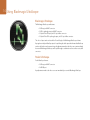
Welcome
4 Welcome
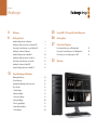
Blackmagic UltraScope Interface
1. Parade Display
2. Waveform Display
3. Vectorscope Display
4. Histogram Display
6. Audio Metering Display
7. Picture Display
5. Error Logging
5 Welcome
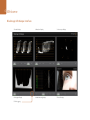
Blackmagic UltraScope
Optical Fiber
3G/HD/SD-SDI In & Out
3G/HD/SD-SDI Output
3G/HD/SD-SDI Input
Pocket UltraScope
USB 3.0 Connection
3G/HD/SD-SDI Input
Getting Started
6 Getting Started
Installation Requirements for Windows
The Blackmagic UltraScope software interface requires a computer display with a minimum resolution
of 1280 x 800 pixels to view two scopes simultaneously. Blackmagic Design recommends viewing all
6 scopes simultaneously by using a computer display resolution of 1920 x 1200 or 1920 x 1080 pixels.
Blackmagic UltraScope includes the UltraScope hardware and a software package which consists of
the Blackmagic UltraScope application and driver. It does not matter in which order the hardware and
software are installed.
Pocket UltraScope hardware connects via USB 3.0. Older computers only have USB 2.0 ports and it is
essential that Pocket UltraScope directly connects to a dedicated USB 3.0 port.
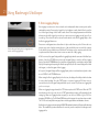
Blackmagic UltraScope hardware is a x1 lane PCI Express card and should work in any x1, x4, x8 or x16
lane PCI Express slot. Blackmagic UltraScope works in PCI Express and PCI Express 2.0 slots.
A x16 lane PCI Express 2.0 slot is required for the graphics card in your computer. The latest list of
compatible graphics cards can be found in the support pages at www.blackmagicdesign.com. Full
frame-rate HD monitoring of all 6 scopes requires either an Nvidia GeForce 9800 GT or faster, or an ATI
Radeon 4670 or faster graphics card. Suitable graphics cards can be purchased for less than US$100.
More expensive graphics cards are no guarantee of compatibility. It is essential to check the list of
compatible graphics cards before buying a graphics card for use with Blackmagic UltraScope. If you
launch the Blackmagic UltraScope application with an incompatible graphics card installed, you may
encounter an error message similar to that pictured on this page. The solution is to replace the graphics
card with a compatible graphics card.
Please see the support pages at www.blackmagicdesign.com for a comprehensive list of the latest,
minimum system requirements for Mac OS X and Windows.
7 Getting Started
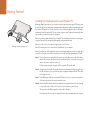
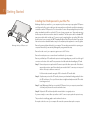
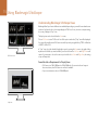
Installing the UltraScope card in your Windows PC
Blackmagic UltraScope installs into your computer in just the same way as any regular PCI Express card.
However the fiber optic module must be temporarily removed from the card before attempting to install
the card in a PCI Express slot. This is because the location of the protruding fiber optic module makes
it awkward to install the card in the PCI ports of many computer cases. Temporarily removing the fiber
optic module overcomes this obstacle to installation.
Remove the power plug from the back of your computer. This is a safety precaution before opening your
computer. Ensure that you are statically discharged by using an antistatic strap.
Remove the side cover of your computer to gain access to the PCIe slots.
Blackmagic UltraScope PCI Express card
Remove the metal port access cover and screw from the back of your computer.
Remove your UltraScope PCIe card from the protective static bag making sure you don’t touch the gold
connectors on the base of the card. These precautions should be taken when handling any PCI card.
Step 1. Remove the protective cap from the LC connector port of the fiber optic module. Don’t throw it
away as the protective cap will be needed to prevent dust if the LC connector port is exposed
when no fiber optic cables are connected.
Pull the wire tab outward to an angle of 90° to release the SFP module latch.
Step 2. Grip the main portion of the SFP module, between your thumb and forefinger, and pull it from
the SFP module port. Do not pull the wire tab as it might break and prevent the SFP module
from being removed.
Step 3. Install Blackmagic UltraScope in a suitable PCI Express slot in your computer, ensure that it
clicks firmly into place and secure the card with a screw.
Step 4. Replace the SFP module and push the wire tab back to its original position. If you are not ready
to connect fiber optic cables to the LC connector port, replace the protective cap.
The procedure for installing a graphics card is similar to the above.
Now replace the side cover of your computer. Reconnect the power and start up the computer.
8 Getting Started
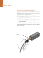
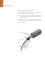
Connecting Pocket UltraScope to your Windows PC
Before using Pocket UltraScope, it’s a good idea to run the latest USB 3.0 drivers and firmware for your
USB 3.0 equipped motherboard. These updates can be found on the websites of motherboard and
computer manufacturers as well as via third party driver websites.
Step 1: Use the included SuperSpeed USB 3.0 cable to connect Pocket UltraScope directly to a
dedicated USB 3.0 port on your compatible computer.
Step 2: If Pocket UltraScope software has previously been installed and offers to update the firmware,
click Update to run the update. When the firmware update is finished, follow the onscreen
prompt to restart the computer.
Pocket UltraScope is now ready for use. You can connect an SDI cable to Pocket UltraScope at any time.
The connection diagrams toward the end of this manual show how to connect Pocket UltraScope to
various kinds of video equipment.
9 Getting Started
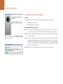
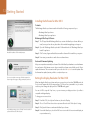
Installing the Software for Windows
Contents
The Blackmagic UltraScope software installer will install the following components for you:
Blackmagic UltraScope drivers
Blackmagic UltraScope application
Blackmagic UltraScope Software
Step 1. The CD supplied with Blackmagic UltraScope contains the UltraScope software. Before you
install, ensure you have the very latest driver. Visit www.blackmagicdesign.com/support
Step 2. Open the “Blackmagic UltraScope Installer” folder and run the “Blackmagic UltraScope
Installer” application.
UltraScope Setup Wizard.
Step 3. Near the end of the software installation process, the software will check the UltraScope
hardware to see what firmware the card contains. If the firmware version does not match the
software version, UltraScope will offer to update the firmware. This is automatic and all you
need to do is click Update to start the update. After the firmware has updated, click the Finish
button to exit the setup wizard.
Step 4. Finally, click Yes to restart your computer and to enable the new software driver.
10 Getting Started
Installation Requirements for Mac OS X
The Blackmagic UltraScope products include the Blackmagic UltraScope hardware card, the Pocket
UltraScope, and a software package which consists of the Blackmagic UltraScope utility and driver. It
does not matter in which order the hardware and software are installed.
Blackmagic Pocket UltraScope connects to your Mac via USB 3.0. The Blackmagic UltraScope hardware is
a x1 lane PCI Express card and should work in any PCI Express slot in a Mac Pro. Both hardware products
are supplied with the UltraScope software utility and driver.
A x16 lane PCI Express 2.0 slot is required for the graphics card in your computer. The latest list of
compatible graphics cards can be found in the support pages at www.blackmagicdesign.com. Full
frame-rate HD monitoring of all 6 scopes requires an EVGA GeForce GTX 285 or faster graphics card.
This card can be purchased for around US$450. More expensive graphics cards are no guarantee of
compatibility. It is essential to check the list of compatible graphics cards before buying a graphics card
for use with Blackmagic UltraScope. The standard graphics card included with a Mac Pro will need to
be replaced with a known compatible card to support all 6 scopes.
The Blackmagic UltraScope software interface requires a computer display with a minimum resolution
of 1280 x 800 pixels to view two scopes simultaneously. Blackmagic Design recommends viewing all 6
scopes simultaneously by using a computer display resolution of 1920 x 1200 or 1920 x 1080 pixels. Refer
to page 13 to see how to change your display resolution. If your Mac cannot display 1920x1200 pixels,
UltraScope can be displayed using “2-up” view.
Please visit the Blackmagic Design support center at www.blackmagicdesign.com/support for a
comprehensive list of the latest minimum system requirements for Mac OS X and Windows.
11 Getting Started
Installing the UltraScope card in your Mac Pro
Blackmagic UltraScope installs in to your computer in just the same way as any regular PCI Express
card. However the fiber optic module must be temporarily removed from the card before attempting
to install the card in a PCI Express slot. This is because the location of the protruding fiber optic module
makes it awkward to install the card in the PCI ports of many computer cases. Temporarily removing
the fiber optic module overcomes this obstacle to installation. The fiber optic module is a standard SFP
transceiver module which includes an LC connector port for attaching fiber optic cables. While other
kinds of optical connectors exist, the SMPTE standard for Optical Fiber SDI specifies that LC type optical
fiber connectors be used and this makes it easy for all compliant optical equipment to connect together.
Blackmagic UltraScope PCI Express card
Remove the power plug from the back of your computer. This is a safety precaution before opening your
computer. Ensure that you are statically discharged by using an antistatic strap.
Remove the side cover of your computer to gain access to the PCIe slots.
Remove the metal port access cover and screw from the back of your computer.
Remove your UltraScope PCIe card from the protective static bag making sure you don’t touch the gold
connectors on the base of the card. These precautions should be taken when handling any PCI card.
Step 1. Remove the protective cap from the LC connector port of the fiber optic module. Don’t throw it
away as the protective cap will be needed to prevent dust if the LC connector port is exposed
when no fiber optic cables are connected.
Pull the wire tab outward to an angle of 90° to release the SFP module latch.
Step 2. Grip the main portion of the SFP module, between your thumb and forefinger, and pull it from
the SFP module port. Do not pull the wire tab as it might break and prevent the SFP module
from being removed.
Step 3. Install Blackmagic UltraScope in a suitable PCI Express slot in your computer, ensure that it
clicks firmly into place and secure the card with a screw.
Step 4. Replace the SFP module and push the wire tab back to its original position.
If you are not ready to connect fiber optic cables to the LC connector port, replace the protective cap.
The procedure for installing a graphics card is similar to the above.
Now replace the side cover of your computer. Reconnect the power and start up the computer.
12 Getting Started
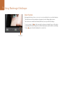
Connecting Pocket UltraScope to your Mac
Step 1: Use the included SuperSpeed USB 3.0 cable to connect Pocket UltraScope directly to a
dedicated USB 3.0 port on your compatible computer.
Step 2: If Pocket UltraScope software has previously been installed and offers to update the firmware,
click Update to run the update. When the firmware update is finished, follow the onscreen
prompt to restart the computer.
Pocket UltraScope is now ready for use. You can connect an SDI cable to Pocket UltraScope at any time.
The connection diagrams toward the end of this manual show how to connect Pocket UltraScope to
various kinds of video equipment.
13 Getting Started
Installing the Software for Mac OS X
Contents
The Blackmagic UltraScope software installer will install the following components for you:
Blackmagic UltraScope drivers
Blackmagic UltraScope application
Blackmagic UltraScope Software
Step 1. The CD supplied with Blackmagic UltraScope contains the UltraScope software. Before you
install, ensure you have the very latest driver. Visit www.blackmagicdesign.com/support
Step 2. Open the “Blackmagic UltraScope Installer” folder and launch the “Blackmagic UltraScope
Installer” application.
Mac OS X installation: Follow install prompts.
Step 3. Click Continue, Agree and Install buttons and the software will be installed on your system.
Step 4. Now restart your machine to enable the new software drivers.
Automatic Firmware Updating
After your computer has restarted, the software will check the UltraScope hardware to see what firmware
the card contains. If the firmware version does not match the software version, UltraScope will offer to
update the firmware. This is automatic and all you need to do is click Update to start the update. After
the firmware has updated, restart your Mac to complete the process.
If you receive the above message, follow the steps at the
bottom right of this page to change your display resolution.
Setting the Display Resolution for Mac OS X
When launching the UltraScope software and your screen resolution is less than 1920x1200 pixels, the
‘2-up’ view will appear with the following message: “Full Screen View is unavailable on your current
resolution, please change the display mode to 1920x1200 and try again.”
You can click OK to stay with ‘2-up’ view, or you can increase your display resolution if your Mac is
compatible with larger displays.
To change your screen resolution:
Step 1. From Mac OS X, select System Preferences, then select Displays.
Step 2. Choose “Scaled” from the resolution options and then select the “More Space” setting.
Step 3. Quit System Preferences and restart the UltraScope software.
In your display settings, choose “Scaled” from the resolution
options and then select “More Space”.
Step 4. From within UltraScope, select View>Full Screen to enter the full screen view and display six
scopes simultaneously.
Using Blackmagic UltraScope
14 Using Blackmagic UltraScope
Blackmagic UltraScope
The Blackmagic UltraScope card features:
1x SDI input, with BNC connector
1x SDI loopthrough output, with BNC connector
1x Optical Fiber SDI input, with LC optical fiber connector
1x Optical Fiber SDI loopthrough output, with LC optical fiber connector
The choice of input can be selected in the Picture Display of the Blackmagic UltraScope software.
Any signal received by an UltraScope input is looped through to both outputs which means that UltraScope
can be used for inline waveform monitoring. Any adjustments made to the video source can immediately
be seen with Blackmagic UltraScope and looped through to a destination such as a video router, deck
or monitor.
Pocket UltraScope
Pocket UltraScope features:
1x SDI input, with BNC connector
1x USB 3.0 port
Any adjustments made to the video source can immediately be seen with Blackmagic UltraScope.
15 Using Blackmagic UltraScope
Understanding Blackmagic UltraScope Views
Blackmagic UltraScope has two different views available depending on your workflow needs and screen
resolution. You have the choice of viewing six displays in “Full Screen” view, or for more compact viewing,
choose any 2 displays in “2-up” view.
The display view can be selected from the View menu.
Choose Full Screen to enter “Full Screen” view. If this option is unchecked, “2-up” view will be displayed.
You can quickly switch between Full Screen view and 2-up view by using the hotkey CTRL-F on Windows
or CMD-F on Mac OS X.
Full Screen view
In “2-up” view, select the desired left and right scopes by opening the View menu or by right-clicking
anywhere in the UltraScope window. Make your selections from the Left View and Right View menu
options. If you attempt to choose the same scopes for both the Left View and Right View, the existing
scopes will swap sides.
Screen Resolution Requirements for Display Views
Full Screen view: 1920 x 1200 pixels or 1920 x 1080 pixels. If your monitor doesn’t support
these resolutions, then Full Screen view will not be available.
2-up view: minimum resolution of 1280 x 800 pixels.
2-Up view
16 Using Blackmagic UltraScope
Zoom Function
Blackmagic UltraScope allows you to zoom in on various displays for a more detailed analysis.
This helpful function will also pan and zoom the graticules for each display in high resolution.
The zoom function is available in the Parade, Waveform, Vectorscope and Picture displays.
To zoom in, simply click
on the bottom right of each respective display. Now you will be able to
view the display in finer detail. Drag the mouse within the display area to pan around the zoomed display.
Clicking
again, will return the display back to its normal view.
Zoom button
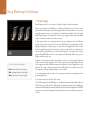
17 Using Blackmagic UltraScope
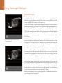
1. Parade Display
Parade Display is perfect for color-correction, checking for illegal colors and checking levels.
When color-correcting, press the RGB button to display the full height of each color channel as red,
green and blue. Monitoring the levels of each red, green and blue color channel makes color-correction
straightforward and it is easy to view color balance in the blacks, mids and whites of the video signal.
Parade Display enables you to identify details common to the red, green and blue channels, making it
simple to color-balance and remove unwanted color tints.
It’s often important when color-correcting to make sure you’re not clipping the video levels. Make sure
the video is full level but not clipped. You can turn on the GAMUT function, and any illegal levels will be
highlighted in bright red, so they are easy to see. Instructions for setting gamut limits can be found in
the Error Logging Display section of this manual. If you want to increase the video level, then make sure
it doesn’t go above upper RGB limit or you will encounter illegal levels. Some equipment won’t let you
generate illegal 100% RGB levels, however other equipment will. Blackmagic UltraScope lets you see
illegal levels whenever they occur.
Color Correction Terminology
Blacks – black levels in the video signal
Mids – mid-gray levels in the video signal
Whites – white levels in the video signal
Illegal video can also happen in blacks as well as whites. In some color-correction systems, black levels
can be lowered to below the black point of 0%. The levels will be shown as bright red if this falls below
the lower gamut limit and the GAMUT warning mode is enabled. If you observe illegal black levels, just
add some “lift” or gain to eliminate them but check the 100% graticule level to make sure the whole
video signal has not lifted and generated illegal colors in the whites.
It’s a constant adjustment process, when color-correcting, to attain the best looking images without
generating illegal levels!
To check levels, simply press the YUV or YUV+ button.
The COLOR setting switches the RGB display to color rather than traditional black and white. When the
COLOR setting is used with the YUV or YUV+ display, luma (brightness) remains white, B-Y (difference
between blue and luma) appears blue and R-Y (difference between red and luma) appears red. The COLOR
setting is not a professional setting and should usually be switched off, especially when showing video
to clients.
18 Using Blackmagic UltraScope
2. Waveform Display
The Waveform Display is similar to traditional composite waveform monitors seen in many broadcast
studios. On Mac OS X, the Waveform Display always shows the luminance view and the B/W button is
permanently selected. On Windows, select B/W for the luminance only view, COMP for the composite
only view, and BOTH for the twin luminance and composite view.
Select B/W for the luminance view which provides a digitally encoded waveform similar to traditional
luminance waveform monitors. The luminance view is very useful when adjusting luma (brightness) levels
in an image. Turn on the GAMUT function, and any illegal luma levels will be highlighted in bright red, so
they are easy to see. Instructions for setting luma limits can be found in the Error Logging Display section
of this manual. Traditional luminance waveform monitors only supported composite analog standard
definition video. However UltraScope’s luminance view works in high definition as well as standard definition,
so you have a consistent and easy way to adjust luma levels even when monitoring high definition digital
video formats!
Waveform Display on Windows can show Luminance,
Composite or Both views.
For Windows users, the composite view is exciting because it’s a fully digitally encoded composite
waveform view and similar to a traditional waveform monitor. This provides a much easier way to align
to test signals, such as color bars, because you can use the composite waveform exactly the same way
as it has always been used. Composite view also works in high definition, so you have a consistent and
traditional way to adjust video even when working in high definition!
When BOTH view is selected on a Windows PC, the composite and luminance waveforms display side by
side in a twin view. This is incredibly useful when adjusting video levels or color correcting. It’s impossible
for a vectorscope to show which objects in the video have color because a vectorscope just shows what
colors are in the whole image and not which objects have color. When color correcting, you often need
to look for specific parts of the image, remove the color and produce a neutral state. This is because the
composite waveform is the same as the luminance signal but with chroma added.
Choosing this twin view makes it easy to identify similar items in the luminance and composite waveforms,
and if more blur or chroma is observed in the composite area, the item has color. If some part of the
video image is neutral gray, then it should look the same on both waveforms because no chroma will
be present. With the twin view, you can look around the waveform and see the levels of color or chroma
of various objects. As you color correct, the composite waveform will display more or less chroma in
the video signal. Now you can see if specific objects in the video image are color or black and white.
You can make technical and creative decisions using the Waveform Display.
Waveform Display on Mac OS X always shows Luminance view.
When the Waveform display is zoomed in, you can toggle between COMP and B/W, and view the same
region of an image in the zoomed display.
19 Using Blackmagic UltraScope
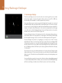
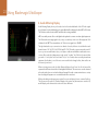
3. Vectorscope Display
The Vectorscope Display uses a vector view to show the colors in a video signal. You can see color bar
video levels by using the color boxes in the graticule. All you need to do is select 75% or 100% color
bars, depending on the standard of color bar test signals used in your facility!
Some people think you can use a vectorscope to check for illegal levels. However this is not correct and
the Parade Display should be used, and set to RGB, for checking for illegal colors. The reason you cannot
use a vectorscope to check for illegal levels is that both chroma and luminance values are required. For
example, colors near the white or black points in video cannot be as saturated as the much stronger
colors, which can be used in the mid-grays. Because Vectorscope Display only shows colors, and not
luminance values, it cannot be used to check for illegal colors.
Vectorscope Display is the best tool for checking color levels from older, analog videotape where you
need to adjust chroma levels. Just play back the color-bar segment of the videotape, and then adjust
the chroma and hue settings, to set the colors of the video within the square boxes in the graticule.
Vectorscope Display is also perfect for color grading, as you can easily see if your video is correctly
white-balanced or if there is a color tint. If your video has a color tint, the Vectorscope display will drift
off-center, and you might see two center dots. Normally the blanking in the video signal will create a
dot in the center of the vector scope, and this is because the blanking in the video is black video without
any color. Blanking provides a useful reference point to help recognize areas of black video without any
color information.
If your video has a color tint, you should see the blacks move off-color and off-center. The degree of shift
represents the amount of color tint in your video and you can see the shift in both the white and black
details of your video. This makes Vectorscope Display valuable for removing color tint and regaining correct
white balance.
Vectorscope Display lets you push colors in your video to the limits, without accidentally adding unwanted
color tints to blacks and whites. While color balance can be monitored on both the RGB Parade Display
and Vectorscope Display, color balance issues will often be easier to see in Vectorscope Display.
20 Using Blackmagic UltraScope
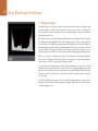
4. Histogram Display
Histogram Display is most familiar to graphic designers and camera operators. Histogram Display
shows the distribution of white to black information and lets you monitor how close the detail is to
being clipped off in the whites or blacks of the video. Histogram Display also lets you see the effects of
gamma changes in the video.
Black video is shown on the left of the display, and whites are shown on the right. All video should usually
be found between the 0% and 100% intervals of the Histogram Display. Your video is being clipped if it
moves below 0% or above 100%. Video clipping can be really bad, when you’re on a shoot, as detail in the
blacks and whites must be preserved if you subsequently want to perform color-correction in a controlled
environment. When shooting, keep the video above the black clip, and below the white clip, so you can
have more freedom later to adjust colors without whites and blacks appearing flat and lacking in detail.
When color-correcting, you might decide to clip your video, and in which case Histogram Display will
show the effect of clipping the video, and how much it is being clipped. You can even use gamma to
create a similar look, with less clipping, while retaining more detail.
You cannot really use Histogram Display to check for illegal levels although you can use it to see illegal
blacks and whites. Histogram Display does not show colors and so the histogram might appear to show
legal levels, even though your video may contain illegal colors. Again, RGB Parade Display provides the
best way to watch out for illegal levels as it shows them in both the color and luminance elements of
the video signal.
The HIGH and LOW buttons simply control how bright the histogram appears on your computer
display. If you find the white area of the histogram is too bright in a dark studio, choose LOW for a more
comfortable brightness level.
21 Using Blackmagic UltraScope
5. Error Logging Display
Error Logging records errors in video and audio and is indispensable when reviewing video and for
unattended operation. Errors may be logged for color, brightness or audio threshold levels as well as
loss of video signal, change of video format or audio silence. After setting the parameters which define
when an error should be logged, you can choose to start or stop error logging, save the log to a file, or
clear the log. These functions can be selected from the buttons in the Error Logging Display or from
the Error Logging pulldown menu.
From the Histogram Display, select the Logging button to
switch to the Error Logging Display.
Errors are recorded against timecode and time of day to make them easy to find. If timecode is not
present, errors can be found by reviewing the time of day at which they were recorded. As computer
clocks can drift, it is a good idea to inspect the Date & Time settings on your computer, and set the clock
to synchronize with an Internet time server to ensure accurate time of day logging.
In Full Screen view, Histogram Display and Error Logging Display share the same area of the UltraScope
interface. Select the LOGGING button, below the Histogram Display, to switch to the Error Logging
Display. Select the HISTOGRAM button, below the Error Logging Display, to switch back to the Histogram
Display. After quitting and reopening the UltraScope application, the last viewed display will be made
visible again, i.e. either Histogram or Error Logging.
In 2-up view, Histogram Display and Error Logging Display can be viewed simultaneously and so there
are no LOGGING or HISTOGRAM buttons.
When viewing the Error Logging Display for the first time, the display will initially be blank other than
for some column headings. Select the START button to commence logging. In Full Screen view, you
can switch back to the Histogram Display and UltraScope will continue to perform error logging until
you choose to stop it.
When error logging is being performed, the STOP button replaces the START button. When the STOP
button has been selected, you can choose to START again and any new errors will be appended to the
existing log. When error logging has been stopped, you can choose to SAVE the log to a CSV file or
alternatively CLEAR the log. The SAVE and CLEAR buttons will not appear if no errors have been recorded.
The CSV file can be analyzed in many applications including spreadsheet and database software.
By default, error logging is performed using the EBU-R103 standard set down by the European Broadcasting
Union. This standard is popular worldwide and is commonly used as a template for making new error
logging profiles.
22 Using Blackmagic UltraScope
How to Customize Error Logging
To customize error logging, go to the Error Logging menu and choose Profiles to open the Error Logging
Profiles window. Saved profiles appear in the profile list at the left and the current, active profile appears
in bold above the list.
The standard EBU-R103 profile cannot be deleted or modified and is grayed out. You can add a profile
by clicking the add (+) button and typing a name for your profile. The new profile will initially contain the
same parameters as the EBU-R103 profile but these can be changed as required.
Under the Gamut tab, upper and lower limits can be adjusted as a percentage of IRE units for RGB, Luma
and Chroma. Set the minimum time in milliseconds (ms) for which these conditions must be sustained
before being logged as errors. Set the percentage area, of pixels in error to total pixels in a frame, below
which errors can be ignored. The Area setting acts like sensitivity.
Under the Audio tab, the maximum audio level can be set in decibels (dBFS) as can the audio level below
which audio is regarded as silence. Set the minimum time in milliseconds (ms) for which these conditions
must be sustained before being logged as errors.
Gamut error tolerance settings for color and brightness
Under the Video tab, loss of video signal and change of video format can be logged as errors.
Under the Notes tab, write a brief description of the new profile to help distinguish it from other profiles.
To modify a new or existing profile, ensure it is selected and then change its parameters as desired.
Press Save to save these changes or choose Revert to leave the profile unchanged.
Choosing Save saves the changes to the profile but does not determine which profile is active. To activate
a profile, select it from the profile list and then choose Set Active.
You can delete a profile by selecting it in the profile list and clicking the delete (–) button.
Audio error tolerance settings
23 Using Blackmagic UltraScope
6. Audio Metering Display
Audio Metering Display shows you the audio levels in the embedded audio of the SDI video signal.
Up to 8 channels of embedded audio are de-embedded and then displayed in either dBFS or VU format.
The VU button switches between dBFS and VU audio metering standards.
dBFS is essentially a meter of the overall digital audio signal and is common on modern digital equipment.
The VU meter shows average signal levels, is easy to use and very common on older equipment. VU is
calibrated to the SMPTE recommendation of a 1 kHz tone test signal set to -20 dBFS.
The right hand audio scope can monitor two channels of audio, which are selected from the audio
channel buttons: CH 1 & 2, CH 3 & 4, CH 5 & 6 and CH 7 & 8. The audio scope presents audio in an X-Y
view so you can see audio balance issues, out of phase conditions and whether an audio track is mono
or stereo. Mono audio should appear as a single, vertical, “in phase” line. If the line is horizontal, then
your audio is “out of phase” and could cancel out (i.e. loss of audio) when received by downstream
equipment. Audio phase is one of the most common audio faults in large facilities, where cables can
be incorrectly connected.
When monitoring stereo audio, the Audio Metering Display will puff out a little like a flower, which
represents the difference between the left and right audio channels. The more stereo sound is contained
in the audio track, the more circular the display will appear. If the audio contains minimal stereo content,
then the display will appear more concentrated around the vertical axis.
While spoken dialog tends to appear as a vertical line, music with plenty of stereo content will puff out.
This is because mono audio is L+R, and will display on the vertical axis, whereas stereo content is L-R,
and will display on the horizontal axis to show the stereo difference.
24 Using Blackmagic UltraScope
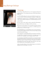
7. Picture Display
The Picture Display is a handy confidence monitor so you can see the video that is being received
by Blackmagic UltraScope. The Picture Display has three settings: COLOR, B/W (black & white) and
BLUE (Blue Only).
Set to COLOR or B/W depending on the needs of your facility. Black & white is popular for use in
color-correction studios so clients don’t get confused when seeing multiple color displays, and not
understanding which color display is the correct, color-calibrated display. You may wish to select B/W
so there is only a single, calibrated, color display in the room. The black & white display can also provide
a useful visual reference.
Blue Only is used with color bar test signals for setting hue on playback decks. When adjusting hue,
make sure all the blue bars are a constant brightness to attain the correct hue level.
Blue Only can also be used for evaluating noise levels in cameras and telecines. Blue has the least amount
of signal level, in a color video signal, and so is more susceptible to noise. The BLUE setting can provide
a good way to check on noise levels in a video signal.
Use the SDI and OPTICAL buttons to select whether UltraScope will receive video from the SDI input or
the optical fiber SDI input. Regardless of which input is chosen, the video input will always loop through
to both the SDI and optical fiber SDI outputs.
The Picture Display will also decode RP-188 HD and VITC SD timecode information, from the SDI video
input signal, and display it on the right side of the display. If the timecode information is incorrect, check
your deck to ensure it is outputting the correct timecode signal encoded as VITC or RP188.
It is worth noting that some standard definition broadcast decks let you “re-stripe” the timecode track
independently of the VITC, which was encoded as part of the image. This meant the VITC could not be
changed without copying the video down another generation. Consequently some standard definition
decks had different timecode in the VITC to the normal LTC track on the SDI video output. It is always
worth checking master tapes if you think the displayed timecode is incorrect.
Lastly, the video standard is displayed on the left side of the Picture Display, so you can verify the video
standard, and confirm you’re monitoring the correct video feed.
Using USB 3.0 Frequently Asked Questions
25 Using USB 3.0 Frequently Asked Questions
Can I use Pocket UltraScope on my Mac?
Yes, you can use a MacBook Pro 15 inch and you will need to set your screen resolution to 1920 x 1200.
If you have a MacBook Pro 13 inch, you will be able to use Pocket UltraScope in a “2-up” view.
Can I use Pocket UltraScope on my Linux PC?
No, Pocket UltraScope is not supported under Linux.
Can I use a third party USB 3.0 PCIe card, in my Mac Pro, with Pocket UltraScope?
No, currently there is not a suitable USB 3.0 PCIe card that is appropriate for use with Pocket UltraScope.
Instead, you can use an UltraScope PCIe card to perform waveform monitoring.
Can I use a third party USB 3.0 PCIe card, in my Windows PC, with Pocket UltraScope?
Yes. Please refer to the Blackmagic Design website:
http://www.blackmagicdesign.com/support for the latest support information, including supported
PCIe cards with USB 3.0.
Can I use a third party USB 3.0 ExpressCard, in my Mac or Windows notebook, with Pocket
UltraScope?
No, currently there is not a USB 3.0 ExpressCard with adequate bandwidth for use with Pocket UltraScope.
What happens if I plug Pocket UltraScope into a USB 2.0 slot?
Pocket UltraScope will not function as USB 2.0 does not provide enough bandwidth for uncompressed
video. A USB 3.0 port is required.
If your computer does not have a suitable USB 3.0 port, but has PCI Express slots, you can use an
UltraScope card on Mac OS X and Windows for waveform monitoring.
What motherboards can I use with Pocket UltraScope?
Motherboards that support Ivy Bridge chipsets are supported.
Which notebooks can I use with Pocket UltraScope?
We currently recommend the MSI GE620. We are in the process of qualifying more notebooks.
Do I need to update my USB 3.0 drivers and firmware to use Pocket UltraScope?
Yes, it is recommended to run the latest Windows USB 3.0 drivers and firmware for your motherboard.
Getting Help
26 Getting Help
There are four steps to getting help.
Step 1. Check out the Blackmagic Design web site www.blackmagicdesign.com and click on the
“Support” page for the latest support information.
Step 2. Call your dealer.
Your dealer will have the latest technical updates from Blackmagic Design and should be able
to give you immediate assistance. We also recommend you check out the support options your
dealer offers as they can arrange various support plans based on your workflow requirements.
Step 3. The next option is to email us with your questions using the web form at
www.blackmagicdesign.com/support
Step 4. Phone a Blackmagic Design support office. Check our web site for current support phone
numbers in your area. www.blackmagicdesign.com/company.
Please provide us with as much information as possible regarding your technical problem and system
specifications so that we may try to respond to your problem as quickly as possible.
Connection Diagrams
27 Connection Diagrams
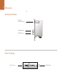
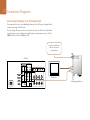
Connecting UltraScope to an SDI digital deck
This example shows how to connect Blackmagic Ultrascope to the SDI output of a digital deck for
waveform monitoring of 4:2:2 HD video.
The loop through SDI output can be connected to an edit suite or an SDI monitor. Optical Fiber
input and output is also provided for running SDI signals over large distances of up to 25 km or
82000 feet in HD, or 45 km or 147000 feet in SD.
Loop thru to additional
edit suite or monitor
via optical fiber
SDI Deck
"Ê6"ÊÉ"
,Ê6"
/Ê1"ÊÉ"Ê-É1®
6"Ê
-Ê"1/*1/
-Ê *1/
"1/
"1/
1"Ê
6"Ê"1/
"1/
£
"*" /Ê6"
"1/
6"Ê
" /,"
/Ê
"
£
Ó
Î
{
£
Ó
Î
{
Ó
" /,"Ê* "1/
Ê
SDI Monitor
Î
,"/ÊÊ
1"Ê"1/
-Ê6"
,"/ÊÊ"1/
"1/
" /",Ê1"
Blackmagic UltraScope
28 Connection Diagrams
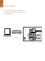
Connecting Pocket UltraScope to an SDI digital deck
This example shows how to connect Pocket Ultrascope to the SDI output of a digital deck for
waveform monitoring of 4:2:2 HD video.
"Ê6"ÊÉ"
,Ê6"
/Ê1"ÊÉ"Ê-É1®
6"Ê
-Ê"1/*1/
-Ê *1/
"1/
"1/
1"Ê
"*" /Ê6"
6"Ê"1/
"1/
£
"1/
6"Ê
" /,"
/Ê
"
£
Ó
Î
{
£
Ó
Î
{
Ó
" /,"Ê* "1/
Ê
Notebook
Pocket UltraScope
Î
,"/ÊÊ
1"Ê"1/
-Ê6"
,"/ÊÊ"1/
"1/
SDI Deck
" /",Ê1"
29 Connection Diagrams
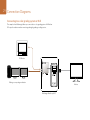
Connecting to a color grading system or NLE
This example shows Blackmagic Ultrascope connected to a color grading system or NLE with an
SDI output for realtime waveform monitoring during the grading or editing session.
SDI Monitor
Editing or compositing workstation
Monitor
Blackmagic UltraScope & PC
Warranty
30 Warranty
3 Year Limited Warranty
Blackmagic Design warrants that this product will be free from defects in materials and workmanship for
a period of 36 months from the date of purchase excluding connectors, cables, cooling fans, fiber optic
modules, fuses, keyboards and batteries which will be free from defects in materials and workmanship
for a period of 12 months from the date of purchase. If a product proves to be defective during this
warranty period, Blackmagic Design, at its option, either will repair the defective product without charge
for parts and labor, or will provide a replacement in exchange for the defective product.
In order to obtain service under this warranty, you the Customer, must notify Blackmagic Design of the
defect before the expiration of the warranty period and make suitable arrangements for the performance
of service. The Customer shall be responsible for packaging and shipping the defective product to a
designated service center nominated by Blackmagic Design, with shipping charges pre paid. Customer
shall be responsible for paying all shipping changes, insurance, duties, taxes, and any other charges for
products returned to us for any reason.
This warranty shall not apply to any defect, failure or damage caused by improper use or improper or
inadequate maintenance and care. Blackmagic Design shall not be obligated to furnish service under
this warranty: a) to repair damage resulting from attempts by personnel other than Blackmagic Design
representatives to install, repair or service the product, b) to repair damage resulting from improper
use or connection to incompatible equipment, c) to repair any damage or malfunction caused by the
use of non Blackmagic Design parts or supplies, or d) to service a product that has been modified or
integrated with other products when the effect of such a modification or integration increases the time
or difficulty of servicing the product. THIS WARRANTY IS GIVEN BY BLACKMAGIC DESIGN IN LIEU OF
ANY OTHER WARRANTIES, EXPRESS OR IMPLIED. BLACKMAGIC DESIGN AND ITS VENDORS DISCLAIM
ANY IMPLIED WARRANTIES OF MERCHANTABILITY OR FITNESS FOR A PARTICULAR PURPOSE.
BLACKMAGIC DESIGN’S RESPONSIBILITY TO REPAIR OR REPLACE DEFECTIVE PRODUCTS IS THE
WHOLE AND EXCLUSIVE REMEDY PROVIDED TO THE CUSTOMER FOR ANY INDIRECT, SPECIAL,
INCIDENTAL OR CONSEQUENTIAL DAMAGES IRRESPECTIVE OF WHETHER BLACKMAGIC DESIGN
OR THE VENDOR HAS ADVANCE NOTICE OF THE POSSIBILITY OF SUCH DAMAGES. BLACKMAGIC
DESIGN IS NOT LIABLE FOR ANY ILLEGAL USE OF EQUIPMENT BY CUSTOMER. BLACKMAGIC IS
NOT LIABLE FOR ANY DAMAGES RESULTING FROM USE OF THIS PRODUCT. USER OPERATES THIS
PRODUCT AT OWN RISK.
© Copyright 2014 Blackmagic Design. All rights reserved. ‘Blackmagic Design’, ‘DeckLink’, ‘HDLink’, ‘Workgroup Videohub’, ‘ Videohub’,
‘DeckLink’, ‘Intensity’ and ‘Leading the creative video revolution’ are registered trademarks in the US and other countries. All other company
and product names may be trade marks of their respective companies with which they are associated.