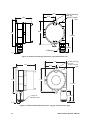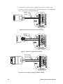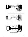
1
M2 Transmitter
Operator’s Manual
Part Number: 71-0107RK
Revision: D
Released: 10/7/10
RKI Instruments, Inc.
www.rkiinstruments.com
WARNING
Read and understand this instruction manual before
operating instrument. Improper use of the gas monitor
could result in bodily harm or death.
Periodic calibration and maintenance of the gas
monitor is essential for proper operation and correct
readings. Please calibrate and maintain this instrument
regularly! Frequency of calibration depends upon the
type of use you have and the sensor types. Typical
calibration frequencies for most applications are
between 3 and 6 months, but can be required more
often or less often based on your usage.
M2 Transmitter Operator’s Manual
Product Warranty
RKI Instruments, Inc. warrants gas alarm equipment sold by us to be free from defects in
materials, workmanship, and performance for a period of one year from date of shipment
from RKI Instruments, Inc. Any parts found defective within that period will be repaired
or replaced, at our option, free of charge. This warranty does not apply to those items
which by their nature are subject to deterioration or consumption in normal service, and
which must be cleaned, repaired, or replaced on a routine basis. Examples of such items
are:
a) Absorbent cartridges
d) Batteries
b) Pump diaphragms and valves
e) Filter elements
c) Fuses
Warranty is voided by abuse including mechanical damage, alteration, rough handling, or
repair procedures not in accordance with the operator’s manual. This warranty indicates
the full extent of our liability, and we are not responsible for removal or replacement costs,
local repair costs, transportation costs, or contingent expenses incurred without our prior
approval.
THIS WARRANTY IS EXPRESSLY IN LIEU OF ANY AND ALL OTHER
WARRANTIES AND REPRESENTATIONS, EXPRESSED OR IMPLIED,
AND ALL OTHER OBLIGATIONS OR LIABILITIES ON THE PART OF
RKI INSTRUMENTS, INC. INCLUDING BUT NOT LIMITED TO, THE
WARRANTY OF MERCHANTABILITY OR FITNESS FOR A
PARTICULAR PURPOSE. IN NO EVENT SHALL RKI INSTRUMENTS,
INC. BE LIABLE FOR INDIRECT, INCIDENTAL, OR CONSEQUENTIAL
LOSS OR DAMAGE OF ANY KIND CONNECTED WITH THE USE OF
ITS PRODUCTS OR FAILURE OF ITS PRODUCTS TO FUNCTION OR
OPERATE PROPERLY.
This warranty covers instruments and parts sold to users by authorized distributors,
dealers, and representatives as appointed by RKI Instruments, Inc.
We do not assume indemnification for any accident or damage caused by the operation of
this gas monitor, and our warranty is limited to the replacement of parts or our complete
goods.
M2 Transmitter Operator’s Manual
Table of Contents
Chapter 1: Introduction . . . . . . . . . . . . . . . . . . . . . . . . . . . . . . . . . . . . . . . . . . . . . . . . . . . . . . . 1
Overview . . . . . . . . . . . . . . . . . . . . . . . . . . . . . . . . . . . . . . . . . . . . . . . . . . . . . . . . . . . . . 1
About the M2 Transmitter . . . . . . . . . . . . . . . . . . . . . . . . . . . . . . . . . . . . . . . . . . . . . . . 1
About this Manual . . . . . . . . . . . . . . . . . . . . . . . . . . . . . . . . . . . . . . . . . . . . . . . . . . . . . . 1
Specifications . . . . . . . . . . . . . . . . . . . . . . . . . . . . . . . . . . . . . . . . . . . . . . . . . . . . . . . . . . 2
Chapter 2: Description . . . . . . . . . . . . . . . . . . . . . . . . . . . . . . . . . . . . . . . . . . . . . . . . . . . . . . . 4
Overview . . . . . . . . . . . . . . . . . . . . . . . . . . . . . . . . . . . . . . . . . . . . . . . . . . . . . . . . . . . . . 4
External Description . . . . . . . . . . . . . . . . . . . . . . . . . . . . . . . . . . . . . . . . . . . . . . . . . . . . 4
Internal Description . . . . . . . . . . . . . . . . . . . . . . . . . . . . . . . . . . . . . . . . . . . . . . . . . . . 10
Chapter 3: Installation & Startup . . . . . . . . . . . . . . . . . . . . . . . . . . . . . . . . . . . . . . . . . . . . . 14
Overview . . . . . . . . . . . . . . . . . . . . . . . . . . . . . . . . . . . . . . . . . . . . . . . . . . . . . . . . . . . . 14
Mounting the M2 Transmitter . . . . . . . . . . . . . . . . . . . . . . . . . . . . . . . . . . . . . . . . . . . 14
Wiring the M2 Transmitter . . . . . . . . . . . . . . . . . . . . . . . . . . . . . . . . . . . . . . . . . . . . . 18
Start Up . . . . . . . . . . . . . . . . . . . . . . . . . . . . . . . . . . . . . . . . . . . . . . . . . . . . . . . . . . . . . . 23
Chapter 4: Operation . . . . . . . . . . . . . . . . . . . . . . . . . . . . . . . . . . . . . . . . . . . . . . . . . . . . . . . . 25
Overview . . . . . . . . . . . . . . . . . . . . . . . . . . . . . . . . . . . . . . . . . . . . . . . . . . . . . . . . . . . . 25
Normal Operation . . . . . . . . . . . . . . . . . . . . . . . . . . . . . . . . . . . . . . . . . . . . . . . . . . . . . 25
Information Screen. . . . . . . . . . . . . . . . . . . . . . . . . . . . . . . . . . . . . . . . . . . . . . . . . . . . . 25
4 - 20 mA Signal Output Operation . . . . . . . . . . . . . . . . . . . . . . . . . . . . . . . . . . . . . . 26
Alarm Indications . . . . . . . . . . . . . . . . . . . . . . . . . . . . . . . . . . . . . . . . . . . . . . . . . . . . . 26
Chapter 5: Configuration Mode . . . . . . . . . . . . . . . . . . . . . . . . . . . . . . . . . . . . . . . . . . . . . . 30
Overview . . . . . . . . . . . . . . . . . . . . . . . . . . . . . . . . . . . . . . . . . . . . . . . . . . . . . . . . . . . . 30
Viewing & Changing M2 Parameters . . . . . . . . . . . . . . . . . . . . . . . . . . . . . . . . . . . . 30
Chapter 6: Gas Type Mode . . . . . . . . . . . . . . . . . . . . . . . . . . . . . . . . . . . . . . . . . . . . . . . . . . . 33
Overview . . . . . . . . . . . . . . . . . . . . . . . . . . . . . . . . . . . . . . . . . . . . . . . . . . . . . . . . . . . . 33
Selecting the Gas Type . . . . . . . . . . . . . . . . . . . . . . . . . . . . . . . . . . . . . . . . . . . . . . . . . 33
M2 Transmitter Operator’s Manual
Chapter 7: Maintenance . . . . . . . . . . . . . . . . . . . . . . . . . . . . . . . . . . . . . . . . . . . . . . . . . . . . . 36
Overview. . . . . . . . . . . . . . . . . . . . . . . . . . . . . . . . . . . . . . . . . . . . . . . . . . . . . . . . . . . . . 36
Preventive Maintenance . . . . . . . . . . . . . . . . . . . . . . . . . . . . . . . . . . . . . . . . . . . . . . . . 36
Troubleshooting . . . . . . . . . . . . . . . . . . . . . . . . . . . . . . . . . . . . . . . . . . . . . . . . . . . . . . . 38
Calibration Frequency . . . . . . . . . . . . . . . . . . . . . . . . . . . . . . . . . . . . . . . . . . . . . . . . . . 40
Calibration, Combustible Gas, CO2, and Toxic Versions . . . . . . . . . . . . . . . . . . . . . 40
Calibration, Oxygen Version . . . . . . . . . . . . . . . . . . . . . . . . . . . . . . . . . . . . . . . . . . . . 43
Replacing Components of the M2 . . . . . . . . . . . . . . . . . . . . . . . . . . . . . . . . . . . . . . . 46
Chapter 8: RS-485 Modbus Output . . . . . . . . . . . . . . . . . . . . . . . . . . . . . . . . . . . . . . . . . . . . 50
Overview. . . . . . . . . . . . . . . . . . . . . . . . . . . . . . . . . . . . . . . . . . . . . . . . . . . . . . . . . . . . . 50
Wiring the M2 in a Modbus System . . . . . . . . . . . . . . . . . . . . . . . . . . . . . . . . . . . . . . 50
Using the M2 in a 4-wire Modbus System . . . . . . . . . . . . . . . . . . . . . . . . . . . . . . . . . 53
Modbus Mode . . . . . . . . . . . . . . . . . . . . . . . . . . . . . . . . . . . . . . . . . . . . . . . . . . . . . . . . 53
Supported Modbus Functions . . . . . . . . . . . . . . . . . . . . . . . . . . . . . . . . . . . . . . . . . . . 55
Parts List . . . . . . . . . . . . . . . . . . . . . . . . . . . . . . . . . . . . . . . . . . . . . . . . . . . . . . . . . . . . . . . . . . 60
Appendix A: Control Button Quick Reference Guide. . . . . . . . . . . . . . . . . . . . . . . . . . . . 64
Appendix B: Function Code 16 Registers . . . . . . . . . . . . . . . . . . . . . . . . . . . . . . . . . . . . . . . 65
(Appendix B available from RKI Instruments, Inc. Not included in manual as normally
provided with M2 detector head.)
M2 Transmitter Operator’s Manual
Chapter 1: Introduction
Overview
This chapter briefly describes the M2 Transmitter. This chapter also describes the M2
Transmitter Operator’s Manual (this document). Table 1 at the end of this chapter lists the
specifications for the M2.
About the M2 Transmitter
The M2 transmitter is a fixed mount, continuous-monitoring detector head. All user
adjustable parameters may be accessed using push button switches. In addition,
calibration may be performed non-intrusively by use of a magnetic wand accessory which
activates magnetic switches through a window at the front face of the detector head.
The M2 displays the current gas reading on an LCD display which is visible through the
window in the cover (front face) and provides a 4 - 20 mA signal which indicates the
target gas reading for use by a gas monitoring controller, recording device, or
programmable controller. The M2 also provides an RS-485 Modbus output. Three sets of
relay contacts, two controlled by the gas alarms and one by the fail alarm, rated at 115
VAC 5 amps are available for controlling devices such as lights or horns or for controlling
higher rated relays.
Four operating modes allow you to display and change setup and calibration settings and
change the gas type. They are Calibration Mode, Configuration Mode, Gas Type Mode,
and Modbus Mode.
About this Manual
The M2 Transmitter Operator’s Manual uses the following conventions for notes, cautions,
and warnings.
NOTE:
Describes additional or critical information.
CAUTION:
WARNING:
1
Describes potential damage to equipment.
Describes potential danger that can result in injury or death.
M2 Transmitter Operator’s Manual
Specifications
Table 1 lists specifications for the M2.
Table 1: M2 Specifications
Target Gas/Detection
Range
Combustible Gas/Carbon Dioxide (CO2)
• Catalytic LEL: 0 - 100% LEL, 1% LEL increments (CH4 calibration
unless otherwise specified. H2 specific detector available)
• IR (infrared) CH4 LEL: 0 - 100% LEL, 1% LEL increments
• IR HC LEL: 0 - 100% LEL, 1% LEL increments (propane calibration)
• IR CH4 Volume: 0 - 100 % volume, 1% increments
• IR CO2 ppm: 0 - 5,000 ppm, 20 ppm increments
• IR CO2 Volume: 0 - 5.00 % volume, 0.01% increments
• IR CO2 Volume: 0 - 50.0 % volume, 0.1% increments
• IR CO2 Volume: 0 - 100 % volume, 1% increments
Oxygen
• Oxygen (O2): 0 - 25.0 % volume, 0.1% increments
CO/H2S
• Carbon Monoxide (CO): 0 - 300 ppm, 1 ppm increments
• Hydrogen Sulfide (H2S): 0 - 100 ppm, 1 ppm increments
ESM-01 Toxic
• Ammonia (NH3): 0 - 75.0 ppm, 0.1 ppm increments
• Arsine (AsH3): 0 - 1.50 ppm, 0.01 ppm increments
• Chlorine (Cl2): 0 - 3.00 ppm, 0.01 ppm increments
• Hydrogen Cyanide (HCN): 0 - 15.0 ppm, 0.1 ppm increments
• Phosphine (PH3): 0 - 1.00 ppm, 0.01 ppm increments
• Sulphur Dioxide (SO2): 0 - 6.00 ppm, 0.01 ppm increments
Alarm Settings
(Alarm 1/Alarm 2)
Combustible Gas (%LEL): 10 %LEL/50 %LEL
Combustible Gas (%Volume): 100 %/100 %
CO2 0 - 5,000 ppm: 2,500 ppm/5,000 ppm
CO2 0 - 5.00%: 0.50 %/3.00 %
CO2 0 - 50.0%: 50.0%/50.0%
CO2 0 - 100%: 100%/100%
Oxygen: 19.5%(decreasing)/23.5%(increasing)
Carbon Monoxide: 25 ppm/50 ppm
Hydrogen Sulfide: 10 ppm/50 ppm
Ammonia: 12 ppm/25 ppm
Arsine: 0.20 ppm/0.50ppm
Chlorine: 0.50 ppm/1.50 ppm
Hydrogen Cyanide: 5.0 ppm/10.0 ppm
Phosphine: 0.10 ppm/0.30 ppm
Sulphur Dioxide: 1.00 ppm/2.00 ppm
Construction
(housing)
Explosion-proof Junction Box, NEMA 4
Area Classification
Explosion-proof for Class I, Groups B, C, and D (Combustible, CO2, CSA
Type CO and H2S, and CSA Type oxygen)
M2 Transmitter Operator’s Manual
2
Table 1: M2 Specifications
Sampling Method
Diffusion
Input Power
19 - 30 VDC
Controls
• Three push button switches
• Three magnetic switches for non-intrusive calibration
Weight
4.5 lbs.
Signal Output
• 4 to 20 mA, 500 ohms impedance max
• RS-485 Modbus
Operating
Temperature
• ESM-01 Type: -10°C to 40 °C
• All Others: -20°C to 50°C
Accuracy
± 5% of full scale
*
These are the RKI factory settings. You can change the alarm settings in Configuration Mode. See
“Viewing & Changing M2 Parameters” on page 30.
WARNING:
3
When using the M2, you must follow the instructions and warnings in
this manual to assure proper and safe operation of the M2 and to
minimize the risk of personal injury. Be sure to maintain and periodically
calibrate the M2 as described in this manual.
M2 Transmitter Operator’s Manual
Chapter 2: Description
Overview
This chapter describes external and internal components of the M2 Transmitter.
External Description
This section describes the junction box and all external components of the M2 transmitter.
Junction Box
Cover
Mounting Hole (2)
3/4 NPT
Conduit Hub
Magnetic
Wand
Window
Detector
(Catalytic LEL Detector Shown)
Figure 1: M2 External Components
Junction Box
The M2’s cast aluminum junction box is dust and weather resistant. The junction box also
protects the M2 and all connections made to it. Use the two 3/4 in. conduit hubs to mount
the detector to the junction box (factory installed in the bottom hub) and connect wiring
from an external device (top hub).
Use the junction box’s two mounting holes to mount the M2 to a vertical surface at the
monitoring site. The window in the cover on the front of the junction box allows you to
view the LCD display and use the magnetic wand to actuate the magnetic control
switches so you can perform non-intrusive calibration. Removing the cover allows you to
access the interior of the junction box.
M2 Transmitter Operator’s Manual
4
Magnetic Wand
The magnetic wand is a short plastic rod with a magnet in one end. It is used to actuate
the magnetic control switches on the control PCB while the junction box cover is still
installed so that non-intrusive calibration can be performed.
Gas Detector
The gas detector senses the target gas and is mounted in a 3/4” conduit hub on the right
bottom side of the M2. A variety of detectors may be used with the M2. Table 2 below lists
the detectors that can be used with the M2.
Table 2: M2 Detectors
5
Target Gas, Range
Detector(s) Used
Combustible Gas, 0 - 100% LEL
•
•
61-0140RK (Catalytic UL version)
61-0140RK-05 (Catalytic CSA version)
Hydrogen, 0 - 100% LEL
•
•
NC-6205-01 (Catalytic UL version, hydrogen specific)
NC-6205-05 (Catalytic CSA version, hydrogen specific)
CH4, 0 - 100% LEL
•
61-0190RK-CH4 (IR UL)
HC, 0 - 100% LEL (cal. to propane)
•
61-0190RK-HC (IR UL)
CH4, 0 - 100% volume
•
61-0192RK-CH4 (IR UL)
CO2, 0 - 5,000 ppm
•
•
61-0191RK-02 (IR UL)
61-0198RK-02 (IR)
CO2, 0 - 5%
•
•
61-0191RK-03 (IR UL)
61-0198RK-03 (IR)
CO2, 0 - 50%
•
•
61-0191RK-05 (IR UL)
61-0198RK-05 (IR)
CO2, 0 - 100%
•
•
61-0191RK-10 (IR UL)
61-0198RK-10 (IR)
Oxygen, 0 - 25%
•
•
•
•
65-2494RK (capillary)
65-2510RK (partial pressure)
65-2511RK (capillary)
65-2514RK (capillary, CSA)
CO, 0 - 300 ppm
•
•
65-2433RK-05 (CSA)
65-2496RK
H2S, 0 - 100 ppm
•
•
65-2423RK-05 (CSA)
65-2495RK
NH3, 0 - 75 ppm
•
65-2300RK-NH3
AsH3, 0 - 1.5 ppm
•
65-2300RK-ASH3
CL2, 0 - 3 ppm
•
65-2300RK-CL2
PH3, 0 - 1 ppm
•
65-2300RK-PH3
SO2, 0 - 6 ppm
•
65-2300RK-SO2
M2 Transmitter Operator’s Manual
The catalytic LEL detectors have a 1/2” NPT thread and require a 3/4”NPT x 1/2”NPT
reducer to install in the detector hub. The rest of the detectors have a 3/4” NPT mounting
thread and are installed directly in the detector hub.
The IR combustible detectors are generally used instead of the catalytic combustible
detectors in applications where there may be catalyst poisons such as silicone present or
where oxygen is not present in the monitoring environment.
Some of the detectors have a replaceable plug-in sensor. These detectors are described and
illustrated below.
There are four types of oxygen detectors available, a non-explosion proof partial pressure
type, a non-explosion proof capillary type, a non-explosion proof capillary type with a
replaceable sensor, and an explosion proof (CSA) capillary type with a replaceable sensor.
The capillary type’s output is less susceptible to variations in atmospheric pressure than
the partial pressure type. The CSA type oxygen detector (65-2514RK) and one of the nonexplosion proof capillary type detectors (65-2494RK) have a replaceable plug-in sensor
inside the detector housing while the entire oxygen detector must be removed if
replacement is required for the other two.
Detector Housing Body
Cap Gasket
Oxygen Sensor
Detector Housing Cap
Flame Arrestor
Guard
Figure 2: 65-2514RK Oxygen Detector, CSA
M2 Transmitter Operator’s Manual
6
Detector Housing Body
Cap Gasket
Plug-In Oxygen Sensor
Detector Housing Cap
Hydrophobic Membrane
Figure 3: 65-2494RK Oxygen Detector, Non-Explosion Proof, Capillary Type
Both types of CO and H2S detectors have replaceable plug-in sensors inside the detector
housing. The CO detector includes a charcoal filter disk which is held onto the sensor with
a rubber retaining boot. The charcoal filter disk scrubs out interfering gases to which the
CO sensor responds such as H2S and certain hydrocarbons.
Detector Housing
Cap Gasket
CO Sensor
Rubber Boot
w/Charcoal Filter Disk
Detector Housing
Cap
Figure 4: 65-2433RK-05 CO Detector, CSA
7
M2 Transmitter Operator’s Manual
Detector Housing Body
Cap Gasket
CO Plug-in Sensor
Charcoal Filter
w/Rubber Boot
Detector
Housing Cap
Hydrophobic
Membrane
Figure 5: 65-2496RK CO Detector Non-Explosion Proof
Detector Housing
Cap Gasket
H2S Sensor
Detector Housing
Cap
Figure 6: 65-2423RK-05 H2S Detector, CSA
M2 Transmitter Operator’s Manual
8
Detector Housing Body
Cap Gasket
H2S Plug-in Sensor
Detector
Housing Cap
Hydrophobic
Membrane
Figure 7: 65-2495RK H2S Detector Non-Explosion Proof
The construction of the various ESM-01 detectors is similar. Each of the ESM-01 detectors
has a different replaceable plug-in sensor that protrudes through the detector housing
cap. Although ESM-01 detectors look the same except for the plug-in detector, the detector
housing which includes the detector socket and conditioning circuitry is specific to a
sensor type. For example, a detector housing from a Cl2 detector cannot be used with an
NH3 detector. One of the two detector wires is color coded for each specific detector type.
The ESM-01 detectors include a removable splashguard that screws onto the detector
housing cap. When it is necessary to apply gas to an ESM-01 detector, remove the
splashguard to allow access to the sensor that protrudes through the detector housing cap.
You can then push the appropriate ESM-01 calibration cup onto the sensor.
Detector Housing Body
(different for each detector type)
Cap Gasket
Sensor
(different for each detector type)
Detector Housing
Cap
Splash Guard
(removable)
Figure 8: ESM-01 Type Detector
9
M2 Transmitter Operator’s Manual
Internal Description
This section describes the internal components of the M2. The internal components of the
M2 include the terminal PCB which provides for all the wiring connections to the M2 and
the control PCB which displays the gas reading and has the control buttons.
NC NO
FAIL
C NC NO
ALARM 1
Fail LED
Alarm 1 LED
Alarm 2 LED
Junction Box
Terminal PCB
Relay
Terminal
Strips
Control PCB
RX LED
TX LED
Magnetic
Switches
ENTER
DOWN/NO
UP/YES
B C
RS 485
A
C NC NO
ALARM 2
R
C
B
A
RS 485
RKI INSTRUMENTS
R
W
W G
LEL
LEL
G
B
C
S
PWR/SIG
B
PWR/SIG
S
3/4" NPT Conduit Opening
For Wire Entry
Power/Signal
Terminal Strip
Detector Terminal Strip
(Comb/CO2 Version Shown)
Detector Current Pot
(Comb/CO2 Type Only,
Factory Adjust)
Programming
Connector
(Factory Use)
M2 TRANSMITTER
Push Button
Control Switches
UP/YES
Modbus
Terminal Strip
DOWN/NO
Display Ribbon
Cable Connector
ENTER
LCD Display
Termination
Jumper
View With Cover and Control
PCB Removed
View with Cover Removed
Figure 9: M2 Internal Components
Terminal PCB
The terminal PCB is encapsulated in epoxy for protection against moisture and physical
damage. It is mounted into the rear of the junction box with three standoffs and rests on a
thin layer of foam. A banana jack is screwed into each of the standoffs and used for
mounting the control PCB. The terminal PCB converts the electrical output from the
detector to a signal which can be displayed by the LCD display, a 4 - 20 mA signal (that is
proportional to the detection range), and an RS-485 Modbus output signal. The 4 - 20 mA
signal may be used by a recording device, gas monitor controller, or programmable
controller. The Modbus output may be used to connect the M2 to a Modbus network. The
terminal PCB also controls three relays, one fail and two gas alarm relays.
Two columns of plug-in style terminal strips are used to make all wiring connections to
the M2. The column on the left consists of the power/signal, detector, and Modbus
terminal strips. The column on the right consists of the relay terminal strips. A 20 position
M2 Transmitter Operator’s Manual
10
connector at the bottom of the terminal PCB is used to connect the terminal PCB to the
control PCB with a ribbon cable. A 5 position connector on the left side of the terminal
PCB is used by factory or field service personnel to program the M2. On the combustible
and CO2 versions of the M2, a factory adjust pot just above the programming connector is
used to set the detector current.
Power/Signal Terminal Strip
The power/signal terminal strip is a three position plug-in style terminal strip located at
the top of the left terminal column. It is used to connect 24 VDC power to the M2 and to
connect the 4 - 20 mA output signal to a device.
The signal output, the S terminal, does not have to be connected for the M2 to function.
The S terminal is used if you want to connect the 4 - 20 mA output signal to another device
such as a gas monitoring controller, chart recorder, or programmable controller (PLC).
Detector Terminal Strip
The detector terminal strip is a four position plug-in style terminal strip and is the middle
terminal strip in the left terminal column. For a combustible or CO2 M2, all four terminals
are used to connect the detector to the M2. For a toxic or oxygen M2, only two of the
terminals are used for connecting a detector: two terminals are dedicated for connecting a
toxic detector and two are dedicated for connecting an oxygen detector (only one detector
can be installed).
B C
RS 485
NC NO
FAIL
C NC NO
ALARM 1
A
C NC NO
ALARM 2
TOXIC
OXY
OXY
TOXIC
C
B
RS 485
A
C NC NO
ALARM 2
C
S
PWR/SIG
NC NO
FAIL
C NC NO
ALARM 1
B
W G
LEL
R
B C
RS 485
A
C
B
A
RS 485
R
W
LEL
G
B
C
S
PWR/SIG
PWR/SIG
S
PWR/SIG
S
Oxy/Toxic Detector
Terminal Strip
Comb/CO2 Detector
Terminal Strip
Figure 10: Detector Terminal Strip
NOTE:
The detector is factory-wired to the M2. See “Wiring the M2 Transmitter” on
page 18 for all wiring procedures related to M2.
Modbus Terminal Strip
The Modbus terminal strip is a three position plug-in style terminal strip and is the
bottom terminal strip in the left terminal column. It allows connection of the M2 into a
Modbus network.
11
M2 Transmitter Operator’s Manual
Relay Terminal Strips
The right column of terminal strips consists of, from top to bottom, the fail, alarm 1, and
alarm 2 relay terminal strips. They are three-position plug-in style terminal strips. The
relay terminal strips are used to connect devices such as lights and horns that are
controlled by the relay contacts. The relay contacts are rated at 115 VAC, 5 amps. The relay
contacts may also be used to control higher rated relays.
Termination Jumper
A two pin header with a termination jumper installed is located below the Modbus
terminal strip. The jumper has no function unless the M2 is wired into a Modbus
installation. See “Chapter 8: RS-485 Modbus Output” on page 50 for a description of using
the M2 in a Modbus system.
Control PCB
The LCD display and control switches are located on the control PCB. It is installed on top
of the terminal PCB by lining up its three spacing standoffs with the banana jacks in the
terminal PCB mounting standoffs and pushing it onto the banana jacks. The jacks retain
the control PCB.
LCD Display
The LCD display is located at the top of the control PCB. It indicates the current gas
reading and displays messages and parameters in the M2’s programs.
Control Buttons
The M2 includes three push button switches that allow you to enter the M2’s operating
modes, navigate through the modes, update settings, and save changes to the settings.
The push button switches are located along the bottom edge of the control PCB (see
Figure 9). The UP/YES button is on the left, the DOWN/NO button is in the middle, and
the ENTER button is on the right.
Table 3: M2 Control Button Functions
Switch
Function
UP (YES)
•
•
•
•
•
Saves settings
Changes the displayed setting
Enters the Calibration Program
Enters Gas Type Mode (press with DOWN/NO button)
Enters Configuration Mode (press with ENTER button)
DOWN (NO)
•
•
•
•
•
Cancels setting changes
Changes the displayed setting
Enters Gas Type Mode (press with UP/YES button)
Enters Modbus Mode (press with ENTER button)
Displays the Information Screen
ENTER
•
•
•
•
Initiates operations
Enters Configuration Mode (press with UP/YES button)
Enters Modbus Mode (press with DOWN/NO button)
Functions as an alarm reset switch
Just above each push button switch is a magnetic switch with the same function as the
push button switch below it. The magnetic switches are for use in non-intrusive
calibration. They are actuated by bringing the magnetic wand close enough to them to
M2 Transmitter Operator’s Manual
12
actuate them. Although the magnetic switches have the same functions as the push button
switches, it is not practical to use them for operations other than calibration because it is
not possible to actuate two magnetic switches at once with only one magnetic wand. Since
displaying the Information Screen only requires the use of one switch, the wand may be
used to show the Information Screen (see “Information Screen” on page 25).
Status LEDs
The M2 includes five status LEDs that are located above the display (see Figure 9).
•
Fail LED
The fail LED turns on when the M2 is experiencing a fail condition. A fail condition
can be caused by a detector failure or low detector signal.
•
Alarm 1 LED
The alarm 1 LED is on when the M2 is experiencing an alarm 1 condition.
•
Alarm 2 LED
The alarm 2 LED is on when the M2 is experiencing an alarm 2 condition.
•
RX & TX LED’s
These LED’s indicate data being received (RX) and transmitted (TX) when the M2’s
Modbus output is operating.
13
M2 Transmitter Operator’s Manual
Chapter 3: Installation & Startup
Overview
This chapter describes procedures to mount the M2 Transmitter in the monitoring
environment and wire it to input power and devices.
Mounting the M2 Transmitter
1.
2.
Select a mounting site that is representative of the monitoring environment. Consider
the following when you select the mounting site.
•
Select a site where the M2 is not likely to be bumped or disturbed. Make sure
there is sufficient room to perform start-up, maintenance, and calibration
procedures.
•
Select a site where the target gas is likely to be found first. For lighter gases,
mount the detector near the ceiling; for heavier gases, mount the detector near the
floor.
At the monitoring site, use #10 screws through the junction box’s two mounting holes
to secure the junction box to a vertical surface. Figure 11 - Figure 17 show the outline
and mounting dimensions for each version of the M2. Mount the M2 with the detector
facing down as shown in the following figures.
5.20
4.60
2.75
.25 Dia. Mounting
Hole, 2X
3/4 NPT Conduit
Hub
5.46
6.10
7.7 max
1 1/2-20 For
Calibration Cup
2.3 max
1.10
Figure 11: Outline & Mounting Dimensions, Catalytic LEL
M2 Transmitter Operator’s Manual
14
5.2
2.75
3.94
.25 Dia. Mounting
Hole, 2X
3/4 NPT Conduit
Hub
5.46
6.1
7.3 max
1.9 max
IR Detector
1.1
Figure 12: Outline & Mounting Dimensions, IR Combustible & CO2
5.20
4.60
6.10
2.75
.25 Dia. Mounting
Hole, 2X
3/4 NPT Conduit
Hub
5.46
8.1 max
1 1/2-20 For
Calibration Cup
2.6 max
1.10
Figure 13: Outline & Mounting Dimensions, Oxygen, Partial Pressure Type
15
M2 Transmitter Operator’s Manual
.25 Dia. Mounting
Hole, 2X
5.20
4.60
3/4 NPT Conduit
Hub
2.75
5.46
6.10
6.8 max
1 1/2-20 For
Calibration Cup
1.4 max
1.10
Figure 14: Outline & Mounting Dimensions, Oxygen, Capillary Type
5.2
2.75
4.60
5.46
6.1
Ø .25 Mouting Holes (2X)
3/4 Conduit Hub
7.0 max
1.50 max
1 1/2-20 For
Calibration Cup
1.1
Figure 15: Outline & Mounting Dimensions, Replaceable Sensor, Non Explosion Proof,
H2S, CO, and Oxygen
M2 Transmitter Operator’s Manual
16
.25 Dia. Mounting
Hole, 2X
3/4 NPT Conduit
Hub
5.20
4.60
2.75
5.46
6.10
8.5 max
3.2
max
1 1/2-20 For
Calibration Cup
1.10
Figure 16: Outline & Mounting Dimensions, CSA Type H2S, CO, and Oxygen
5.2
2.75
4.60
6.1
Ø .25 Mouting Holes (2X)
3/4 Conduit Hub
5.46
9.82 max
4.37 max
1.1
Figure 17: Outline & Mounting Dimensions, ESM-01 Toxic
17
M2 Transmitter Operator’s Manual
Wiring the M2 Transmitter
WARNING:
Always verify that the power source is OFF before making any wiring
connections.
1.
Remove the junction box cover.
2.
Grasp the control PCB by its edges.
3.
Gently pull until the control PCB is pulled away from the banana jacks. Take care not
to pull too hard and damage the cable which connects the control and terminal PCB’s.
4.
Let the control PCB hang by the cable. The terminal strips are now visible on the
terminal PCB. The control PCB may be left hanging while wiring is done. If desired,
the control PCB may be disconnected from the cable and set aside while wiring.
5.
The detector leads are factory wired. Verify that the detector leads are wired to the
detector terminal strip as shown in the applicable figure below:
•
Catalytic LEL/Combustible IR/CO2 Detectors
NC NO
FAIL
C NC NO
ALARM 1
A
C NC NO
ALARM 2
B C
RS 485
C
B
A
RS 485
R
R
W
W G
LEL
LEL
G
B
B
C
PWR/SIG
S
Black
Green
White
Red
S
PWR/SIG
The wiring for these types of detectors is the same. Red wire to terminal labeled
LEL R, white wire to terminal labeled LEL W, green wire to terminal labeled LEL
G, black wire to terminal labeled LEL B.
NC NO
FAIL
C NC NO
ALARM 1
B
W G
LEL
C NC NO
ALARM 2
R
B C
RS 485
A
C
B
A
RS 485
R
W
LEL
G
B
C
S
PWR/SIG
Black
Green
White
Red
PWR/SIG
S
Figure 18: Catalytic LEL Detector Wiring
Figure 19: Combustible IR/CO2 Detector Wiring
M2 Transmitter Operator’s Manual
18
•
Oxygen Detector, Partial Pressure, Capillary Type, and CSA Capillary Type
The wiring for all the oxygen detectors is the same. White wire to terminal labeled
OXY +, green wire to terminal labeled OXY -.
NC NO
FAIL
C NC NO
ALARM 1
C NC NO
ALARM 2
B C
RS 485
C
A
B
A
RS 485
TOXIC
TOXIC
OXY
OXY
C
PWR/SIG
S
White
S
PWR/SIG
Green
Figure 20: Partial Pressure Oxygen Detector Wiring
NC NO
FAIL
C NC NO
ALARM 1
C NC NO
ALARM 2
B C
RS 485
C
A
B
A
RS 485
TOXIC
TOXIC
OXY
OXY
C
PWR/SIG
S
White
S
PWR/SIG
Green
Figure 21: Capillary Oxygen Detector Wiring
NC NO
FAIL
C NC NO
ALARM 1
C NC NO
ALARM 2
A
B C
RS 485
C
B
A
RS 485
TOXIC
TOXIC
OXY
OXY
C
S
PWR/SIG
White
PWR/SIG
S
Green
Figure 22: CSA Capillary Type Oxygen Detector Wiring
19
M2 Transmitter Operator’s Manual
C NC NO
ALARM 1
+
OXY
A
A
B C
RS 485
C NC NO
ALARM 2
+
TOXIC
TOXIC
+
RS 485
B C
White
C NC NO
FAIL
- S
+
PWR/SIG
PWR/SIG
- S
+
OXY
+
-
Green
Figure 23: Capillary Type Replaceable Sensor Oxygen Detector Wiring
•
CSA type CO or H2S gas detector.
C NC NO
ALARM 1
A
C NC NO
ALARM 2
B C
RS 485
C
B
A
RS 485
TOXIC
TOXIC
OXY
OXY
C
Red
NC NO
FAIL
PWR/SIG
S
Black
S
PWR/SIG
Red wire to terminal labeled TOXIC +, black wire to terminal labeled TOXIC -.
Figure 24: H2S/CO Detector Wiring, CSA
•
Non Explosion Proof CO or H2S gas detector
C NC NO
FAIL
C NC NO
ALARM 1
+
OXY
+
TOXIC
B C
RS 485
A
C NC NO
ALARM 2
- S
+
PWR/SIG
+
S
-
OXY
+
-
TOXIC
+
RS 485
B C
Red
A
Black
PWR/SIG
Red wire to terminal labeled TOXIC +, black wire to terminal labeled TOXIC -.
Figure 25: H2S/CO Detector Wiring
M2 Transmitter Operator’s Manual
20
•
ESM-01 Toxic Detectors
Wire Color
NC NO
FAIL
C NC NO
ALARM 1
C NC NO
ALARM 2
A
B C
RS 485
C
A
See Chart
B
RS 485
TOXIC
TOXIC
OXY
OXY
C
Black
S
PWR/SIG
PWR/SIG
S
The ESM-01 toxic detectors have one black wire and one color coded wire. Connect the
color coded wire (see chart below) to the terminal labeled TOXIC + and the black wire to
the terminal labeled TOXIC -.
Gas Type
Brown
AsH3
Yellow
Cl2
Red
NH3
Orange
NO
Green
PH3
Blue
SO2
Figure 26: ESM-01 Toxic Detector Wiring
6.
To gain access to a plug-in terminal strip for wiring, pull it out of its socket by
grasping the wall between two terminal positions with needle nose pliers and pulling.
Be careful not to exert too much force on the wall to avoid damage to the terminal
strip. The detector terminal strip and the alarm 1 relay terminal strip may be removed
by grasping them with your fingers if the adjacent terminal strips have been removed.
WARNING:
7.
Guide multi conductor shielded cable or cables or wires in conduit through the top
conduit hub of the junction box. The number of cables or wires needed will depend on
whether the M2 is wired to a gas monitoring controller or just to power, whether any
relays are used, and whether the Modbus output is used. Use the following
recommendations to determine how to wire the M2:
•
21
If the M2 is installed in a hazardous location, use appropriately rated
conduit, conduit fittings, and appropriate construction technique that
complies with the local electrical code.
In addition, use appropriately rated conduit, conduit fittings, and
appropriate construction technique to maintain the NEMA 4
environmental rating of the junction box and avoid water entering the
junction box at the conduit hubs.
If Modbus connections will not be used and only the PWR/SIG connections will
be used, use a two or three conductor shielded cable or two or three wires in
conduit for connections to the power/signal terminal strip depending on whether
or not the signal (S) terminal is used. The S terminal has a 4 - 20 mA output, but if
you do not need to monitor this signal and do not connect to the S terminal to
M2 Transmitter Operator’s Manual
access this signal, the M2 will still function completely.
Table 4: Wire Size for PWR/SIG Connections
Max Distance to Controller
w/18 Gauge Wire
2,500 ft.
Max Distance to Controller
w/16 Gauge Wire
5,000 ft.
•
8,000 ft.
If the PWR/SIG connections and one or more relays are used, route the
connections to the M2 in conduit. Use shielded cable in the conduit for the PWR/
SIG connections and unshielded cable or individual wires for the relay
connections. Make sure any wire or cable used for relay wiring is appropriately
rated for the power that it will carry.
NOTE:
•
Max Distance to Controller
w/14 Gauge Wire
If shielded cable is used for the PWR/SIG connections, leave the cable shield’s
drain wire insulated and disconnected at the M2. You will connect the opposite
end of the cable’s drain wire at the controller or device.
If the M2 will be wired into a Modbus network, see “Chapter 8: RS-485 Modbus
Output” on page 50.
See Figure 27 below for field wiring connections to the M2.
Alarm Device
Power
S
PWR/SIG
(24 VDC)
B C
RS 485
See
Modbus
Wiring
Alarm 1 Alarm
Device
C NC NO
ALARM 1
A
(24 VDC)
TOXIC
See
Detector
Wiring
C NC NO
ALARM 2
OXY
C
4 - 20 mA In (S)
Fail Alarm
Device
NC NO
FAIL
Controller
Terminals
Alarm 2 Alarm
Device
Typical Alarm
Wiring Shown
Figure 27: Wiring the M2 to a Controller and Alarm Devices
8.
Re-install the control PCB (and ribbon cable if necessary). Be sure the ribbon cable is
routed down below the control PCB so it will not be damaged by the cover when it is
screwed back on.
9.
Secure the junction box cover to the junction box.
10. Make controller, device, and relay connections as appropriate. If shielded cable is
used for the PWR/SIG connections, connect the cable shield’s drain wire to an
M2 Transmitter Operator’s Manual
22
available chassis ground at the gas monitoring controller, recording device, or
programmable controller.
Start Up
Introducing Incoming Power
1.
Complete the installation procedures described earlier in this manual.
2.
Verify that all wiring connections are correct and secure.
3.
Turn on the incoming power.
4.
If necessary, turn on the controller or other monitoring device that is connected to the
M2.
5.
The LCD display will indicate the firmware version when the M2 is first powered up
and will then count down a one minute warm-up period before normal operation
begins. During normal operation, the display will indicate the target gas and current
gas reading. Verify that the display is indicating the target gas and current gas reading
after the warm-up period is complete and normal operation begins.
METHANE
0 %LEL
NOTE:
Allow the M2’s detector to warm up for 15 minutes before you continue with
the next section, “Adjusting the Fresh Air Reading.”
Adjusting the Fresh Air Reading
When the M2 is shipped from RKI Instruments, Inc., it is factory calibrated. If a full
calibration is desired at startup, see “Calibration, Combustible Gas, CO2, and Toxic
Versions” on page 40 or “Calibration, Oxygen Version” on page 43.
Verify that the M2 is in a fresh air environment (environment known to be free of the
target gas and combustible or toxic gas vapors and of normal oxygen content, 20.9%).
CAUTION:
If you suspect the presence of combustible gas, CO2, toxic gas, or that the oxygen
content is not normal in the monitoring environment, use the calibration kit and
the zero air calibration cylinder to introduce “fresh air” to the detector and verify
an accurate fresh air setting. See the “Calibration, Combustible Gas, CO2, and
Toxic Versions” on page 40 or “Calibration, Oxygen Version” on page 43 for
instructions on how to use a zero air cylinder when performing a fresh air
adjustment.
Non-Intrusive Fresh Air Signal Adjustment
If the M2 is installed in a classified area and non-intrusive zero adjustment is required,
follow the instructions below, but do not remove the junction box cover. Use the
magnetic wand accessory to actuate the magnetic switches instead of pushing the control
switch buttons. To actuate a magnetic switch and perform the same operation as pressing
a control switch button, touch the magnet in the end of the magnetic wand to the M2’s
glass cover directly over the magnetic switch you wish to actuate. Touching the glass and
removing the wand is the same as pressing and releasing a button. Touching the glass and
keeping the wand in place is the same as pressing and holding a button.
23
M2 Transmitter Operator’s Manual
WARNING:
NOTE:
The M2 is not an active gas monitoring device during the fresh air
adjustment procedure. The 4-20 mA output signal will “freeze” at 3.5 mA
for a toxic, combustible gas, or CO2 M2, or at 17.4 mA for an oxygen M2,
and all relays will remain in their non-alarm state while the M2 is in
Calibration Mode. The output signal will not indicate current readings
and the relays will not resume operating normally until the M2 is in
normal operation again.
While in the calibration program, if there is no switch activity for the
calibration time-out period the unit will return to normal operation. The factory
set time-out is 15 minutes. If you want a different time-out period, see
“Viewing & Changing M2 Parameters” on page 30 for instructions to change
the calibration time-out.
Combustible Gas, CO2, and Toxic Versions, Adjusting the Fresh Air Reading
1.
While in normal operation, press and hold the UP/YES button for 5 seconds to enter
Calibration Mode. Release the button when the following screen appears.
Calib?
YES/NO
2.
Press and release the UP/YES button to continue. The display will indicate the target
gas and CAL Mode for a few seconds before showing FreshAir Adjust?.
3.
Press and release the UP/YES button. ENTER will alternate with FreshAir on the top
display line and the current gas reading will be on the bottom display line.
4.
Press and release the ENTER button. The M2 will perform a zero operation and the
display will indicate SPAN w/Cal Gas?.
5.
Press and release the DOWN/NO button. The display will indicate Leaving CAL
Mode and the M2 will return to normal operation.
Oxygen Version, Adjusting the Fresh Air Reading
1.
While in normal operation, press and hold the UP/YES button for 5 seconds to enter
Calibration Mode. Release the button when the following screen appears.
Calib?
YES/NO
2.
Press and release the UP/YES button to continue. The display will indicate OXYGEN
CAL Mode for a few seconds before showing FreshAir Adjust?.
3.
Press and release the UP/YES button. ENTER will alternate with FreshAir on the top
display line and the current oxygen reading will be on the bottom display line.
4.
Press and release the ENTER button. The M2 will perform a span operation and then
the display will indicate ZERO w/Cal Gas?.
5.
Press and release the DOWN/NO button. The display will indicate Leaving CAL
Mode and the M2 will return to normal operation.
M2 Transmitter Operator’s Manual
24
Chapter 4: Operation
Overview
This chapter describes the M2 in normal operation. This chapter also describes the M2 in
alarm 1, alarm 2, and fail conditions and suggests responses to these conditions.
Normal Operation
Normal operation is defined as follows:
•
The start-up procedure is complete.
•
The M2 is not indicating an alarm 1, alarm 2, or fail condition.
•
The M2 is not in Calibration, Configuration, or Gas Type modes.
During normal operation, the M2 simultaneously displays the current gas reading, unit of
measure, and target gas. The example below illustrates a typical combustible gas M2.
METHANE
0 %LEL
Information Screen
The Information Screen displays the M2’s operating voltage and firmware and hardware
information. To display the Information Screen, do the following:
1.
Press and hold the DOWN/NO button for 3 seconds. The Information Screen will
appear.
24.2V
v5.0L 2A
25
2.
Continue holding the DOWN/NO button to keep the Information Screen on the
display. The top line indicates the operating voltage that is connected to the M2. The
second line indicates the firmware that is running, version 5.0 in this example, and the
M2’s hardware version, version 2A in this example. This information may be useful if
you need to contact the factory with questions about the M2.
3.
Release the DOWN/NO button when you are done viewing the Information Screen.
The display will return to the normal operation screen within a couple of seconds.
M2 Transmitter Operator’s Manual
4 - 20 mA Signal Output Operation
The output at the S terminal of the power/signal terminal strip is a 4 - 20 mA signal that
corresponds to the detection range of the M2. During normal operation, this signal tracks
the gas concentration on the LCD.
There are several circumstances where the signal output will not track the display reading
but will behave as follows:
•
When the M2 is in its warm-up period, the signal output will be fixed at 3.5 mA (zero)
for all gas types except oxygen. For oxygen types, the output will be fixed at 17.4 mA
(20.9% oxygen) while the M2 is in warm-up.
•
When the M2’s gas type is changed, the M2 will enter Configuration Mode for you to
verify the parameter settings. When you exit Configuration Mode, the display will
indicate NEEDS CALIBRATION and will continue to indicate this until Calibration
Mode is entered and a calibration is performed. In this situation, the signal output will
be fixed at 3.5 mA for LEL and toxic versions and 17.4 mA for oxygen versions from
the time Gas Type Mode is entered until the M2 is calibrated and returns to normal
operation.
•
If you enter Calibration Mode, Configuration Mode, Gas Type Mode, or Modbus
Mode, the signal output will be fixed at 3.5 mA for combustible gas, CO2, and toxic
versions and 17.4 mA for oxygen versions until the M2 returns to normal operation.
•
If the M2’s input power decreases below 18.5 volts so that the M2 is in a low power
alarm, the signal output is fixed below 2.4 mA until the low power alarm is cleared.
•
If the M2 goes into a fail condition, the signal output is fixed below 2.4 mA until the
fail alarm is cleared.
Alarm Indications
NOTE:
The M2 includes alarm on and alarm off delay settings for alarm 1 and alarm 2.
The alarm indications described in this section operate according to the factory
set alarm settings. See Table 6 on page 31 for all the factory settings.
Table 5: Visual and Audible Alarm Indications
Condition
Cause
Visual Indication(s)
Alarm 11
Increasing (decreasing for O2) gas
reading at or above the alarm 1
setpoint
• A1 LED is on
• Gas reading alternates
with ALARM-1 message
Alarm 21
Increasing gas reading at or above the
alarm 2 setpoint
• A2 LED is on
• Gas reading alternates
with ALARM-2 message
Fail
• Disconnected or misconnected
detector wiring
• Display reading at -10% of full
scale or lower
• Defective components
• F LED is on
• FAIL message replaces
gas reading
M2 Transmitter Operator’s Manual
26
Table 5: Visual and Audible Alarm Indications
Condition
Low Power
*
Cause
Visual Indication(s)
DC power source less than 18.5 volts.
• F LED is on
• LowPower message and
actual voltage of
incoming DC power
1If
the M2 is in both an alarm 1 and an alarm 2 condition, both alarm LEDs are on and the
display alternates between the gas reading and the ALMS 1&2 message.
NOTE:
You can select normally energized (N. EN) or normally de-energized (N. DEEN) alarm 1 and alarm 2 relay settings in Configuration Mode. The following
sections describe the standard factory setting for these relays which is
N. DE-EN.
The fail relay is factory set as N. EN and is not user-adjustable.
Alarm 1 Condition
Alarm 1 Condition Indications
When the gas reading reaches the alarm 1 setpoint, the M2 senses an alarm 1 condition.
The M2 alerts you to an alarm 1 condition as follows:
•
The A1 LED turns on.
•
The gas reading alternates with the ALARM-1 message.
•
The alarm 1 relay energizes.
Responding to an Alarm 1 Condition
1.
Follow your established procedure for a low level combustible or toxic gas condition
or a decreasing oxygen concentration condition.
2.
After the gas reading falls below (above for oxygen) the alarm 1 setpoint, press the
ENTER button to reset the alarm 1 circuit. Resetting the alarm 1 circuit turns off the
A1 LED, resets the LCD, and de-energizes the alarm 1 relay.
NOTE:
If the ENTER button is pressed while the M2 is in an alarm 1 condition, the A1
LED will flash but all other indications will remain unchanged.
You cannot de-energize the alarm 1 relay until the gas reading falls below
(above for oxygen) the alarm 1 setpoint.
Alarm 2 Condition
Alarm 2 Condition Indications
When the gas reading reaches the alarm 2 setpoint, the M2 senses an alarm 2 condition.
The M2 alerts you to an alarm 2 condition as follows:
27
•
The A2 LED turns on.
•
The gas reading alternates with the ALARM-2 message.
•
The alarm 2 relay energizes.
M2 Transmitter Operator’s Manual
NOTE:
If the M2 is in both an alarm 1 and alarm 2 condition, both the A1 and A2 LEDs
will be on, the gas reading will alternate with the ALMS 1&2 message, and
both alarm relays will energize.
Responding to an Alarm 2 Condition
1.
Follow your established procedure for a high level combustible or toxic gas condition
or an increasing oxygen concentration condition.
2.
After the gas reading falls below the alarm 2 setpoint, press the ENTER button to reset
the alarm circuit. Resetting the alarm circuit turns off the A2 light, resets the LCD, and
de-energizes the alarm 2 relay.
NOTE:
If the ENTER button is pressed while the M2 is in an alarm 2 condition, the A2
LED will flash but all other indications will remain unchanged.
You cannot de-energize the alarm 2 relay until the gas reading falls below the
alarm 2 setpoint.
Fail Condition
Fail Condition Indications
The M2 indicates a fail condition for any of the following:
•
The detector wiring is disconnected or incorrectly connected.
•
The display reading is -10% of full scale or lower.
When the M2 senses a fail condition, it alerts you as follows:
•
The F LED turns on.
•
The gas reading is replaced by the FAIL message.
•
The fail relay de-energizes.
Responding to a Fail Condition
1.
Verify that the detector wiring is correctly and securely connected.
2.
If the M2 has a replaceable plug-in sensor, verify that the replaceable plug-in sensor in
the detector housing is properly installed.
Low Power Alarm
Low Power Alarm Indications
The M2 senses a low power condition when the DC power source is 18.5 volts or less.
WARNING:
While in a low power condition, the M2 is not an active gas monitor.
When the M2 senses a low power condition, it alerts you as follows:
•
The F LED turns on.
•
The message LowPower is indicated on the top line of the LCD and the input voltage
is displayed on the bottom line of the LCD.
•
The fail relay de-energizes.
M2 Transmitter Operator’s Manual
28
NOTE:
The low power alarm cannot be cleared using the ENTER button.
When the voltage increases to 19.0 volts, the low power alarm is cleared and the M2 will
begin its warm-up sequence.
Responding to a Low Power Condition
29
1.
Determine and correct the cause of the low power condition.
2.
When the input power increases above 19.0 volts, the M2 will begin its warm-up
sequence.
3.
Verify that the M2 enters normal operation after its warm-up sequence. If necessary,
perform a fresh air adjustment. See “Adjusting the Fresh Air Reading” on page 23.
M2 Transmitter Operator’s Manual
Chapter 5: Configuration Mode
Overview
This chapter describes how to view and change M2 parameters using Configuration
Mode. It is accessed using the program buttons.
Configuration Mode includes a 5-minute time-out feature. If you do not press a control
button for 5 minutes, the M2 automatically returns to normal operation.
NOTE:
If the M2 returns to normal operation because of a time-out, it enters a warmup period just as it does when it is first turned on.
If you are installing a new M2, it has been setup at the factory. Use
Configuration Mode only if you want to change the M2’s setup. If you want to
change the detector type see “Chapter 6: Gas Type Mode” on page 33.
Viewing & Changing M2 Parameters
1.
While in normal operation, simultaneously press and hold the UP/YES and ENTER
buttons for 5 seconds to enter Configuration Mode. Release the buttons when the
following screen appears.
Enter
Config?
2.
If you want to exit Configuration Mode, press and release the DOWN/NO button and
the M2 will return to normal operation.
If you want to continue in Configuration Mode, press and release the UP/YES button.
The target gas and the full scale will be displayed for a few seconds before the first
adjustable parameter, the alarm 1 setpoint, is displayed.
3.
If you want to change the currently displayed parameter, use the UP/YES and
DOWN/NO buttons to adjust it to the desired setting, then press ENTER to continue
to the next parameter.
If the currently displayed parameter is OK, press the ENTER button to proceed to the
next parameter.
Table 6 lists the M2 parameters you can set. Table 6 also lists the factory set value for
each parameter.
M2 Transmitter Operator’s Manual
30
Table 6: Configuration Parameters
Parameter
(Factory Set Value)
Description
ALARM-1 (level)
(See “M2 Specifications” on page 2)
The gas reading at which the M2 initiates an alarm 1 condition.
ALARM-1 (activation)
(Decrease for oxygen M2, Increase for
all other types)
Indicates if the alarm 1 circuit is activated by gas readings increasing
(Increase) or decreasing (Decrease) to the ALARM-1 Level.
ALARM-1 (relay action)
(N. DE-EN)
If set as N. DE-EN, the alarm 1 relay is de-energized in normal operation
and energizes when an alarm 1 condition is initiated.
If set as N. EN, the alarm 1 relay is energized in normal operation and
de-energizes when an alarm 1 condition is initiated.
ALARM-1 (relay reset)
(LATCH)
If set as LATCH, you must press the ENTER button to reset the alarm 1
circuit after the alarm 1 condition passes.
If set as SELF-RST, the M2 automatically resets the alarm 1 circuit after
the alarm 1 condition passes.
A1 OnDy (alarm 1 on delay)
(1 secs)
The amount of time the M2 delays activation of the alarm 1 circuit once
an alarm 1 condition is initiated. It can be set in 1 second increments
from 0 - 60 seconds, in 1 minute increments from 1 - 15 minutes, and in
15 minute increments from 15 - 60 minutes.
A1 OffDy (alarm 1 off delay)
(0 sec.)
The amount of time the M2 delays turning off the alarm 1 circuit once an
alarm 1 condition passes. This parameter appears only if the alarm 1
relay reset setting is set to SELF-RST. It can be set in 1 second
increments from 0 - 60 seconds, in 1 minute increments from 1 - 15
minutes, and in 15 minute increments from 15 - 60 minutes.
ALARM-2 (level)
(See “M2 Specifications” on page 2)
The gas reading at which the M2 initiates an alarm 2 condition.
ALARM-2 (activation)
(Increase for all types)
Indicates if the alarm 2 circuit is activated by gas readings increasing
(Increase) or decreasing (Decrease) to the ALARM-1 Level.
ALARM-2 (relay action)
(N. DE-EN)
If set as N. DE-EN, the alarm 2 relay is de-energized in normal operation
and energizes when an alarm 2 condition is initiated.
If set as N. EN, the alarm 2 relay is energized in normal operation and
de-energizes when an alarm 2 condition is initiated.
ALARM-2 (relay reset)
(LATCH)
If set as LATCH, you must press the ENTER button to reset the alarm 2
circuit after the alarm 2 condition passes.
If set as SELF-RST, the M2 automatically resets the alarm 2 circuit after
the alarm 2 condition passes.
A2 OnDy (alarm 2 on delay)
(1 secs)
The amount of time the M2 delays activation of the alarm 2 circuit once
an alarm 2 condition is initiated. It can be set in 1 second increments
from 0 - 60 seconds, in 1 minute increments from 1 - 15 minutes, and in
15 minute increments from 15 - 60 minutes.
A2 OffDy (alarm 2 off delay)
(0 sec.)
The amount of time the M2 delays turning off the alarm 2 circuit once an
alarm 2 condition passes. This parameter appears only if the alarm 2
relay reset setting is set to SELF-RST. It can be set in 1 second
increments from 0 - 60 seconds, in 1 minute increments from 1 - 15
minutes, and in 15 minute increments from 15 - 60 minutes.
31
M2 Transmitter Operator’s Manual
Table 6: Configuration Parameters (Continued)
Parameter
(Factory Set Value)
Description
ZeroSupp
(0.5% oxygen for oxygen types, 2% of
the detection range in terms of the
detection units for all other types)
The zero suppression feature helps prevent “jumpy” readings near the
fresh air reading.
For example, if the zero suppression setting for a combustible LEL
detector is 2.0% LEL, the M2 will display a reading of 0% LEL for gas
readings from -2% LEL to 2% LEL. It is settable from 0 to 6% of the
detection range.
FILTER
(5 secs)
The filter feature helps “smooth out” jumpy or noisy signals from the
detector. You can set the filter from 0 seconds to 60 seconds in 5
seconds increments.
The displayed gas reading is the average reading over the previous time
period defined by the filter setting. So if the filter is set to 5 seconds, the
displayed gas reading is the average over the past 5 seconds.
CAL Time
(15 mins)
The calibration time-out sets the amount of time after the last button push
while in Calibration Mode that the M2 will wait before returning to normal
operation. If the calibration time-out is set to 15 mins, then M2 will return
to normal operation automatically 15 minutes after the last button push.
Auto Zero
(Enabled)
If set to Enabled, the M2’s firmware will monitor the zero (fresh air)
reading and make automatic zero adjustments under precisely specified
conditions if it determines that a reading change is due to normal sensor
drift.
If set to Disabled, the Auto Zero function is turned off.
4.
When you have scrolled through all the adjustable parameters, SAVE IT? YES/NO
appears on the display.
5.
If you do not wish to save the adjustments and want to exit Configuration Mode,
press and release the DOWN/NO button. The DO OVER? YES/NO message will
display. Press and release the DOWN/NO button. The ABORT? YES/NO message
will display. Press the UP/YES button to return to normal operation.
If you wish to change some of the adjustments made, press and release the DOWN/
NO button. The DO OVER? YES/NO message will display. Press and release the UP/
YES button. The Re-do Config message will display and the M2 will return to the first
adjustable parameter. Go back to step 3 and continue.
If you wish to save the adjustments made, press and release the UP/YES button.
Config Saved is indicated on the display for a few seconds and the M2 returns to
normal operation.
M2 Transmitter Operator’s Manual
32
Chapter 6: Gas Type Mode
Overview
This chapter describes how to use Gas Type Mode to select the M2’s gas type. The gas type
determines the target gas and detection range. The combustible gas/CO2 and toxic/
oxygen M2s have a different terminal PCB and run on different firmware. Your M2 will
only have gas type choices available that it can support.
Gas Type Mode includes a 5-minute time-out feature. If you do not press a button for 5
minutes, the M2 automatically returns to normal operation.
NOTE:
If the M2 enters normal operation because of a program time-out, it enters a
warm-up period just as it does when it is first turned on.
Selecting the Gas Type
1.
While in normal operation or during the warm-up sequence, press and hold the UP/
YES and DOWN/NO buttons for five seconds. Release them when the following
screen appears.
Select
GasType?
2.
If you want to exit Gas Type Mode, press and release the DOWN/NO button. The
display will indicate NO CHANGE and the M2 will return to normal operation.
If you want to continue in Gas Type Mode, press and release the UP/YES button. The
top display line will indicate GasType? and the bottom display line will indicate the
target gas choice.
3.
Use the UP/YES or DOWN/NO button to scroll through the choices of target gas.
Table 7 and Table 8 below list the choices of target gas for the M2.
Table 7: Combustible Gas/CO2 Gas Types
Gas Type
Choices
33
Detection Range
HC
0 - 100% LEL
iBUTANE
0 - 100% LEL
PROPANE
0 - 100% LEL
HEXANE
0 - 100% LEL
HYDROGEN
0 - 100% LEL
METHANE
0 - 100% Volume
METHANE
0 - 100% LEL
M2 Transmitter Operator’s Manual
Table 7: Combustible Gas/CO2 Gas Types
Gas Type
Choices
Detection Range
CO2
0 - 5,000 ppm
CO2
0 - 2,000 ppm
CO2
0 - 100% volume
CO2
0 - 50.0% volume
CO2
0 - 5.00% volume
NH3
0 - 5.00% volume
NH3
0 - 2.00% volume
Table 8: Toxic/Oxygen Gas Types
Gas Type
Choices
Detection Range
H2S
0 - 100 ppm
CO
0 - 300 ppm
OXYGEN
0 - 25.0% volume
SIH4
0 - 15.0 ppm
SI2H6
0 - 15.0 ppm
PH3
0 - 1.00 ppm
O3
0 - 1.00 ppm
NO
0 - 100 ppm
HF
0 - 9.00 ppm
HCN
0 - 15.0 ppm
HCL
0 - 15.0 ppm
H2SE
0 - 5.00 ppm
GEH4
0 - 1.50 ppm
F2
0 - 3.00 ppm
CLO2
0 - 1.00 ppm
B2H6
0 - 5.00 ppm
ASH3
0 - 1.50 ppm
SO2
0 - 6.00 ppm
NH3
0 - 200 ppm
M2 Transmitter Operator’s Manual
34
Table 8: Toxic/Oxygen Gas Types
Gas Type
Choices
NOTE:
Detection Range
NH3
0 - 75.0 ppm
CL2
0 - 3.00 ppm
Consult factory for availability of detectors for toxic M2 types not listed in “M2
Specifications” on page 2.
4.
When the desired target gas is on the display, press and release the ENTER button.
The display will ask SAVE IT? YES/NO.
5.
To discard the gas type change, press and release the DOWN/NO button. The display
will ask DO OVER? YES/NO. Press the DOWN/NO button. The display will ask
ABORT? YES/NO. Press the UP/YES button. The M2 will return to normal operation
without changing the gas type.
To save the gas type, press and release the UP/YES button. The display will indicate
Gas Type Updated, the display will indicate the target gas and the detection range for
a few seconds, and then the M2 will enter Configuration Mode automatically so that
the parameter settings in Configuration Mode can be verified or changed.
6.
While in Configuration Mode press and release the ENTER button to accept the
displayed parameter setting and move to the next one. Use the UP/YES and DOWN/
NO buttons to adjust a setting. See “Chapter 5: Configuration Mode” on page 30 for a
complete description of Configuration Mode.
7.
When you have reviewed and accepted the last item in Configuration Mode by
pressing the ENTER button, display will ask SAVE IT? YES/NO.
8.
To save the configuration settings, press and release the UP/YES button.The display
will indicate Config Saved and the M2 will begin its warm-up sequence.
To discard the settings and review them again, press the DOWN/NO button. The
display will ask DO OVER? YES/NO. Press the UP/YES button and the display will
indicate Re-do Config, then display the target gas and the detection range for a few
seconds before returning to Configuration Mode. Repeat steps 6 - 8 until the settings
are as desired.
9.
After the M2 completes its warm-up sequence, the display will indicate CAL
NEEDED. Since the gas type has been changed, a successful calibration must be
performed before the M2 can enter normal operation.
10. Press and release the UP/YES button to enter Calibration Mode. Normally, you must
hold the UP/YES button for 5 seconds to enter Calibration Mode, but since a
calibration is required, only a momentary push is needed to enter Calibration Mode
after changing the gas type.
11. See “Calibration, Combustible Gas, CO2, and Toxic Versions” on page 40 or
“Calibration, Oxygen Version” on page 43 for calibration instructions.
NOTE:
35
When calibrating an M2 after changing the gas type, the M2 will not ask if you want to calibrate, or
whether you want to perform a fresh air adjustment, span adjustment or zero adjustment. Since a
complete calibration is required, the calibration sequence will proceed without asking if you want to
perform certain operations.
M2 Transmitter Operator’s Manual
Chapter 7: Maintenance
Overview
This chapter describes procedures for performing preventive maintenance,
troubleshooting, calibrating the M2, and replacing field replaceable parts. It includes
separate procedures for calibrating the combustible gas/CO2/toxic and oxygen versions
of the M2.
Preventive Maintenance
This section describes a recommended preventive maintenance schedule to ensure the
optimum performance of the M2. It includes daily, monthly, and quarterly procedures.
Daily
Verify a display reading of zero (20.9% for an oxygen M2). Investigate significant changes
in the reading.
Monthly
This procedure describes a test to verify that the M2 responds properly to the target gas.
NOTE:
Performing a response test on the M2 may cause alarms. If you do not want
external alarms to actuate, disable any external alarms during the response test
to avoid unwanted external alarm indications.
NOTE:
The following procedure assumes the use of a calibration kit which includes a
calibration gas cylinder, a fixed flow regulator with an on/off knob, a
calibration cup for the detector, and a short piece of sample tubing to connect
the regulator to the calibration cup.
1.
Disable all external alarms if external alarm indications are not desired during the
response test.
2.
Connect the calibration kit sample tubing to the calibration cup hose barb.
3.
Screw the calibration cup onto the detector.
NOTE:
4.
For an ESM-01 detector, you must unscrew the removable splashguard from
the detector housing cap so you can push the appropriate calibration cup onto
the ESM-01 sensor. Make sure to use the correct calibration cup for the sensor
being used. There is a Cl2 type calibration cup for a Cl2 sensor, an NH3 type
calibration cup for an NH3 sensor, and a general type (usually labeled SO2)
calibration cup for all other ESM-01 sensors.
Connect the fixed flow regulator to the calibration cup using the sample tubing.
M2 Transmitter Operator’s Manual
36
NOTE:
When applying gas to an NH3 ESM-01, the 0.25 LPM flowrate regulator must
be used. All other M2s require a 0.5 LPM flowrate regulator.
5.
Screw the calibration gas cylinder into (onto for an H2S cylinder) the fixed flow
regulator.
6.
Turn the regulator knob counterclockwise to open the regulator.
7.
Allow calibration gas to flow for one minute.
8.
Verify that the display reading is within ± 20% of the gas concentration.
NOTE: If the reading is not within ± 20% of the gas concentration, calibrate the M2 as
described in “Calibration, Combustible Gas, CO2, and Toxic Versions” on
page 40 or “Calibration, Oxygen Version” on page 43.
9.
Turn the regulator knob clockwise to close the regulator.
10. Unscrew the calibration gas cylinder from the fixed flow regulator and unscrew the
calibration cup from the detector.
For an ESM-01 detector, pull the calibration cup off the ESM-01 sensor and screw the
splashguard back onto the detector housing cap.
11. If external alarms have been disabled, enable them when the display returns to a
normal fresh air reading.
12. Store the components of the calibration kit in a safe place.
Quarterly
Calibrate M2s that do not have an IR detector as described in “Calibration, Combustible
Gas, CO2, and Toxic Versions” on page 40 or “Calibration, Oxygen Version” on page 43.
See “Calibration Frequency” on page 40 for a discussion of calibration frequency
guidelines.
Biannually
Calibrate M2s that have an IR detector as described in “Calibration, Combustible Gas,
CO2, and Toxic Versions” on page 40. See “Calibration Frequency” on page 40 for a
discussion of calibration frequency guidelines.
37
M2 Transmitter Operator’s Manual
Troubleshooting
The troubleshooting guide describes symptoms, probable causes, and recommended
action for problems you may encounter with the M2.
NOTE: This troubleshooting guide describes M2 problems only. If the M2 is connected to
a controller, see the controller operator’s manual for problems you may
encounter with the controller.
Table 9:Troubleshooting the Combustible Gas Detector
Condition
Symptom(s)
Probable Causes
Recommended Action
No Power
The display backlight
is off and the display
screen is blank.
• The power wiring is
disconnected or
misconnected.
• The display cable is
disconnected or
misconnected.
1. Verify that the wiring to the
power source or controller is
correct and secure.
2. Verify that the ribbon cable
connecting the terminal PCB to
the control PCB is securely
installed. This ribbon cable plugs
into a connector on the top edge
of the control PCB and on the
bottom of the terminal PCB.
3. If the power difficulties continue,
contact RKI for further
instruction.
Frequent or
Suspect
Alarms
The M2 alerts you to
frequent or suspect
alarms while the
fresh air readings
remain on zero (20.9
for oxygen).
• The M2 is
experiencing false
readings due to RFI
or EMI.
• The detector wiring
is disconnected,
misconnected, or
intermittent.
1. Verify that the M2 wiring is
properly shielded. See “Wiring
the M2 Transmitter” on page 18.
2. Verify that the detector wiring is
correct and secure.
3. Increase the alarm on delay
setting in Configuration Mode.
4. If the frequent or suspect alarm
difficulties continue, contact RKI
for further instruction.
Flickering
Display
The display reading
flickers often.
• The M2 is
experiencing false
readings due to RFI
or EMI.
• The noise filter
setting is too low.
• The zero
suppression setting
is too low.
• The display screen
is malfunctioning.
1. Verify that the M2 wiring is
properly shielded. See “Wiring
the M2 Transmitter” on page 18.
2. Verify that the detector wiring is
correct and secure.
3. Increase the filter setting in
Configuration Mode.
4. Increase the zero suppression
setting in Configuration Mode.
5. If the display difficulties continue,
contact RKI for further
instruction.
M2 Transmitter Operator’s Manual
38
Table 9:Troubleshooting the Combustible Gas Detector (Continued)
Condition
Symptom(s)
Probable Causes
Recommended Action
Fail
Condition
• M2 indicates a fail
condition.
• Controller
indicates a fail
condition
• The detector wiring
to the terminal PCB
is disconnected or
misconnected.
• The wiring from the
M2 to the controller
is disconnected or
misconnected.
• The detector fresh
air signal is low
enough to cause a
fail condition.
• The detector is
malfunctioning.
• The terminal or
display PCB is
malfunctioning.
1. Verify that the detector wiring is
correct and secure.
2. Verify that the wiring between the
M2 and the controller is correct
and secure.
3. Calibrate the M2.
4. If the fail condition continues,
replace the detector.
5. If the fail condition continues,
contact RKI for further
instruction.
Slow or No
Response/
Difficult or
Unable to
Calibrate
• M2 responds
slowly or does not
respond to
response test.
• Unable to
successfully set
the fresh air or
span (zero for
oxygen) reading
during
calibration.
• M2 requires
frequent
calibration.
• The calibration
cylinder is low, outdated, or defective.
• The detector is
malfunctioning.
• The terminal PCB is
malfunctioning.
1. Verify that the calibration cylinder
contains an adequate supply of a
fresh test sample.
2. If the calibration/response
difficulties continue, replace the
detector.
3. If the calibration/response
difficulties continue, contact RKI
for further instruction.
Note: See “Calibration
Frequency” on page 40 for
calibration frequency
guidelines.
39
M2 Transmitter Operator’s Manual
Calibration Frequency
Some M2s have IR (infrared) type detectors, such as an M2 for CO2 or an LEL M2 with an
IR detector. Most of the M2s do not have an IR detector. For example, an H2S M2 has an
electrochemical detector and some of the combustible M2s use catalytic detectors. The
M2s that use IR detectors typically need less frequent calibration as is discussed below.
See Table 1, “M2 Specifications,” on page 2 to see which M2s are IR versions.
Although there is no particular calibration frequency that is correct for all applications, a
calibration frequency of every 3 to 6 months for M2s that do not have an IR detector and
every 6 to 12 months for M2s that have an IR detector is adequate for most M2
applications. Unless experience in a particular application dictates otherwise, RKI
Instruments, Inc. recommends a calibration frequency of every 3 months for M2s that do
not have an IR detector and every 6 months for M2s that have an IR detector.
If an application is not very demanding, for example detection in a clean, temperature
controlled environment where the toxic or combustible target gas is not normally present,
and calibration adjustments are minimal at calibration, then a calibration frequency of
every 6 months for a non-IR M2 or 12 months for an IR M2 is adequate.
If an application is very demanding, for example if a combustible or toxic gas is present
often and in significant concentrations or the environment is not well controlled, then
more frequent calibration than every 3 months for a non-IR M2 or every 6 months for an
IR M2 may be necessary. For combustible gas detection with an M2 that uses a catalytic
detector, if potential catalyst poisons are known or likely to be present, more frequent
calibration than every 3 months will be necessary.
Calibration, Combustible Gas, CO2, and Toxic Versions
This section describes how to calibrate the combustible gas, CO2, and toxic gas versions of
the M2. It includes procedures to prepare for calibration, enter Calibration Mode, adjust
the fresh air (zero) setting, adjust the span setting, and return to normal operation. See the
next section, “Calibration, Oxygen Version” for instructions to calibrate an oxygen M2.
WARNING:
The M2 is not an active gas monitoring device during the calibration
procedure. The 4-20 mA output signal will “freeze” at 3.5 mA and all
relays will remain in their non-alarm state while the M2 is in Calibration
Mode. The output signal will not indicate current readings and the relays
will not resume operating normally until the M2 is in normal operation
again.
Preparing for Calibration
NOTE:
The following procedure assumes the use of a calibration kit which includes a
calibration gas cylinder, a zero air cylinder, a fixed flow regulator with an on/
off knob, a calibration cup for the appropriate sensor, and a short piece of
sample tubing to connect the regulator to the calibration cup.
M2 Transmitter Operator’s Manual
40
NOTE:
While in the calibration program, if there is no switch activity for the
calibration time-out period the unit will return to normal operation. See
“Viewing & Changing M2 Parameters” on page 30 for instructions to set the
calibration time-out.
NOTE:
The following procedure assumes that the target gas is present in a high
enough concentration to affect the fresh air (zero) reading. If a fresh air
environment can be verified, applying zero air to the detector is not necessary
when setting the zero (span for oxygen) reading.
1.
Connect the calibration kit sample tubing to the calibration cup hose barb.
2.
Screw the calibration cup onto the detector.
NOTE:
3.
For an ESM-01 detector, you must unscrew the removable splashguard from
the detector housing cap so you can push the appropriate calibration cup onto
the ESM-01 sensor. Make sure to use the correct calibration cup for the sensor
being used. There is a Cl2 type calibration cup for a Cl2 sensor, an NH3 type
calibration cup for an NH3 sensor, and a general type (usually labeled SO2)
calibration cup for all other ESM-01 sensors.
Connect the fixed flow regulator to the calibration cup using the sample tubing.
NOTE:
When calibrating an NH3 ESM-01, the 0.25 LPM flowrate regulator must be
used. All other M2s require a 0.5 LPM flowrate regulator.
Non-Intrusive Calibration
If the M2 is installed in a classified area and non-intrusive calibration is required, follow
the instructions below, but do not remove the junction box cover. Use the magnetic wand
accessory to actuate the magnetic switches instead of pushing the control switch buttons.
To actuate a magnetic switch and perform the same operation as pressing a control switch
button, touch the magnet in the end of the magnetic wand to the M2’s glass cover directly
above the magnetic switch you wish to actuate. Touching the glass and removing the
wand is the same as pressing and releasing a button. Touching the glass and keeping the
wand in place is the same as pressing and holding a button.
Calibration Gas Response Memory Feature
The M2 has the capability to “remember” the detector’s response to the calibration gas
after the gas is removed from the detector during the fresh air and span adjustment
procedure. This feature enables one person to perform calibration if the detector is
mounted remotely from the M2. When zero air is applied to the M2 during a fresh air
adjustment, the M2 will freeze the display reading at the lowest response and the M2 will
continue to display this reading and retain it in its memory until the fresh air adjustment
procedure is completed. When calibration gas is applied to the M2 during a span
adjustment, the M2 will freeze the display reading at the highest response to the
calibration gas. The calibration gas can then be removed and the M2 will continue to
display this reading and retain it in its memory until the span adjustment procedure is
completed.
41
M2 Transmitter Operator’s Manual
Adjusting the Fresh Air Reading
1.
While in normal operation, press and hold the UP/YES button for 5 seconds to enter
Calibration Mode. Release the button when the following screen appears.
Calib?
YES/NO
2.
If you want to continue with calibration, press and release the UP/YES button. The
display will indicate the target gas and CAL Mode for a few seconds before showing
FreshAir Adjust?.
If you want to exit Calibration Mode, press and release the DOWN/NO button. The
M2 will indicate Leaving CAL Mode and the M2 will return to normal operation.
3.
To continue with adjusting the fresh air reading, press and release the UP/YES button.
ENTER will alternate with FreshAir on the top display line and the current gas
reading will be on the bottom display line.
To skip adjusting the fresh air reading, press and release the DOWN/NO button. The
display will indicate SPAN w/Cal Gas?. Skip to the next section, “Adjusting the Span
Setting”.
4.
Screw the zero air cylinder into the fixed flow regulator.
5.
Turn the regulator knob counterclockwise to open the regulator.
6.
Allow zero air to flow for two minutes. If there was gas present causing a reading on
the M2, the reading should decrease and stabilize after two minutes.
7.
Turn the regulator knob clockwise to close the regulator.
8.
Unscrew the zero air cylinder from the fixed flow regulator leaving the calibration cup
on the detector. The M2 will continue to display the minimum gas response on the
display and retain the response level in its memory.
9.
Press and release the ENTER button. The M2 will perform a fresh air adjustment and
the display will indicate SPAN w/Cal Gas?.
NOTE:
If the fresh air adjustment fails, see “Troubleshooting” on page 38 for
recommended actions.
Adjusting the Span Setting
1.
If you want to continue with adjusting the span setting, press and release the UP/YES
button. APPLY will alternate with SPAN Gas on the top display line and the current
gas reading will be on the bottom display line.
If you want to skip adjusting the span reading, press and release the DOWN/NO
button. The display will indicate Leaving Cal Mode and the M2 will return to normal
operation.
2.
Screw the calibration gas cylinder into (onto for an H2S cylinder) the fixed flow
regulator.
3.
Turn the regulator knob counterclockwise to open the regulator.
4.
Allow calibration gas to flow for two minutes. The gas reading should be stable after
two minutes.
5.
Turn the regulator knob clockwise to close it.
M2 Transmitter Operator’s Manual
42
6.
Unscrew the calibration gas cylinder from the fixed flow regulator and unscrew the
calibration cup from the detector. For an ESM-01 detector, pull the calibration cup off
of the ESM-01 sensor and screw the splashguard back onto the detector housing cap.
The M2 will continue to display the maximum gas response on the display and retain
the response level in its memory.
7.
Adjust the gas reading up or down to match the calibration gas cylinder concentration
by using the UP/YES and DOWN/NO buttons, then press and release the ENTER
button.
8.
The M2 will perform a span operation. The display will indicate SPAN Gas PASS for
a few seconds, then indicate SPAN Gas SAVED before indicating Leaving CAL Mode
for a few seconds.
NOTE:
9.
If the span adjustment fails, see “Troubleshooting” on page 38 for
recommended actions.
The display will now alternate between the normal operation screen and the message
REMOVE CAL GAS for 1 minute. If the calibration gas has not been removed from
the detector, remove it now to avoid unwanted alarms.
During this 1 minute period, the signal output will remain fixed at 3.5 mA and the
relays will remain in their non-alarm state to avoid unwanted alarms while the
calibration gas clears from the detector. At the end of the 1 minute period, the
REMOVE CAL GAS message will stop appearing and the M2 will return to normal
operation.
10. Store the components of the calibration kit in a safe place.
Calibration, Oxygen Version
This section describes how to calibrate the oxygen version of the M2. It includes
procedures to prepare for calibration, enter Calibration Mode, set the fresh air (span)
reading, set the zero reading, and return to normal operation.
WARNING:
The M2 is not an active gas monitoring device during the calibration
procedure. The 4-20 mA output signal will “freeze” at 17.4 mA and all
relays will remain in their non-alarm state while the M2 is in Calibration
Mode. The output signal will not indicate current readings and the relays
will not resume operating normally until the M2 is in normal operation
again.
Preparing for Calibration
NOTE:
43
The following procedure assumes the use of a calibration kit which includes a
zero air (20.9% oxygen) calibration cylinder to set the fresh air reading, a 100%
nitrogen (0% oxygen) calibration gas cylinder to set the zero reading, a fixed
flow regulator with an on/off knob, a calibration cup, and a short piece of
sample tubing to connect the regulator to the calibration cup. A cylinder with
up to an 18% oxygen concentration may be used instead of a 100% nitrogen
cylinder to set the zero reading.
M2 Transmitter Operator’s Manual
NOTE:
While in calibration mode, if there is no switch activity for the calibration timeout period the unit will return to normal operation. See “Viewing & Changing
M2 Parameters” on page 30 for instructions to set the calibration time-out.
NOTE:
The following procedure assumes that the oxygen concentration in the
calibration area is not normal, 20.9%, but is oxygen deficient. If a fresh air
environment can be verified, applying zero air to the detector is not necessary
when adjusting the fresh air (span) setting.
1.
Connect the calibration kit sample tubing to the calibration cup hose barb.
2.
Screw the calibration cup onto the detector.
3.
Connect the fixed flow regulator to the calibration cup using the sample tubing.
Non-Intrusive Calibration
If the M2 is installed in a classified area and non-intrusive calibration is required, follow
the instructions below, but do not remove the junction box cover. Use the magnetic wand
accessory to actuate the magnetic switches instead of pushing the control switch buttons.
To actuate a magnetic switch and perform the same operation as pressing a control switch
button, touch the magnet in the end of the magnetic wand to the M2’s glass cover directly
above the magnetic switch you wish to actuate. Touching the glass and removing the
wand is the same as pressing and releasing a button. Touching the glass and keeping the
wand in place is the same as pressing and holding a button.
Calibration Gas Response Memory Feature
The M2 has the capability to “remember” the detector’s response to the calibration gas
after the gas is removed from the detector during the fresh air or zero adjustment
procedure. This feature enables one person to perform a calibration if the detector is
mounted remotely from the M2. When zero air is applied to the M2 during a fresh air
adjustment, the M2 will freeze the display reading at the highest response and the M2 will
continue to display this reading and retain it in its memory until the fresh air adjustment
procedure is completed. When calibration gas is applied to the M2 during a zero
adjustment, the M2 will freeze the display reading at the lowest response to the calibration
gas. The calibration gas can then be removed and the M2 will continue to display this
reading and retain it in its memory until the zero adjustment procedure is completed.
Adjusting the Fresh Air Setting
1.
While in normal operation, press and hold the UP/YES button for 5 seconds to enter
Calibration Mode. Release the button when the following screen appears.
Calib?
YES/NO
2.
If you want to continue with calibration, press and release the UP/YES button to
continue. The display will indicate OXYGEN CAL Mode for a few seconds before
showing FreshAir Adjust?.
If you want to exit Calibration Mode, press and release the DOWN/NO button. The
M2 will indicate Leaving CAL Mode and the M2 will return to normal operation.
3.
To continue with adjusting the fresh air (span) reading, press and release the UP/YES
button. ENTER will alternate with FreshAir on the top display line and the current
M2 Transmitter Operator’s Manual
44
oxygen reading will be on the bottom display line.
To skip adjusting the fresh air reading, press and release the DOWN/NO button. The
display will indicate ZERO w/Cal Gas?. Skip to the next section, “Adjusting the Zero
Setting”.
4.
Screw the zero air cylinder into the fixed flow regulator.
5.
Turn the regulator knob counterclockwise to open the regulator.
6.
Allow zero air to flow for 2 minutes. If the oxygen concentration in the area is less
than 20.9, the reading should stabilize after 2 minutes.
7.
Turn the regulator knob clockwise to close the regulator.
8.
Unscrew the zero air cylinder from the fixed flow regulator leaving the calibration cup
on the detector. The M2 will continue to display the maximum gas response on the
display and retain the response level in its memory.
9.
Press and release the ENTER button. The M2 will perform a fresh air adjustment and
the display will indicate ZERO w/Cal Gas?.
NOTE:
If the fresh air adjustment fails, see “Troubleshooting” on page 38 for
recommended actions.
Adjusting the Zero Setting
1.
If you want to continue with adjusting the zero setting, press and release the UP/YES
button. APPLY will alternate with ZERO Gas on the top display line and the current
oxygen reading will be on the bottom display line.
If you want to skip adjusting the zero reading, press and release the DOWN/NO
button. The display will indicate Leaving Cal Mode and the M2 will return to normal
operation.
2.
Screw the 100% nitrogen gas cylinder into the fixed flow regulator.
3.
Turn the regulator knob counterclockwise to open the regulator.
4.
Allow gas to flow for 2 minutes. The gas reading should be stable after 2 minutes.
5.
Turn the regulator knob clockwise to close the regulator.
6.
Unscrew the nitrogen cylinder from the fixed flow regulator and unscrew the
calibration cup from the detector. The M2 will continue to display the minimum gas
response on the display and retain the response level in its memory.
7.
Adjust the oxygen reading up or down to match the 100% nitrogen cylinder oxygen
concentration of 0 by using the UP/YES and DOWN/NO buttons.
NOTE:
8.
Press and release the ENTER button. The M2 will perform a zero operation. The
display will indicate ZERO Gas PASS for a few seconds, then indicate ZERO Gas
SAVED before indicating Leaving CAL Mode for a few seconds.
NOTE:
45
If a cylinder other than a 100% nitrogen (0% oxygen) cylinder is used to set the
zero reading, such as a cylinder with 12% oxygen, set the zero reading to match
the cylinder’s oxygen concentration.
If the zero adjustment fails, see “Troubleshooting” on page 38 for
recommended actions.
M2 Transmitter Operator’s Manual
9.
The display will now alternate between the normal operation screen and the message
REMOVE CAL GAS for 1 minute. If the calibration gas has not been removed from
the detector remove it now to avoid unwanted alarms.
During this 1 minute period, the signal output will remain fixed at 17.4 mA and the
relays will remain in their non-alarm state to avoid unwanted alarms while the
calibration gas clears from the detector. At the end of the 1 minute period, the
REMOVE CAL GAS message will stop appearing and the M2 will return to normal
operation.
10. Store the components of the calibration kit in a safe place.
Replacing Components of the M2
Replacing the Gas Detector
NOTE:
For M2 versions that do not have a replaceable plug-in sensor, or if you
determine that it is necessary to replace the entire detector, use the procedure in
this section to change the entire detector. For M2 versions that include a
replaceable plug-in sensor, see the appropriate instructions in the sections that
follow this one to replace the plug-in sensor.
1.
Turn off or disconnect power to the M2.
2.
Remove the junction box cover.
3.
Grasp the control PCB by its edges.
4.
Gently pull until the control PCB is pulled away from the banana jacks. Take care not
to pull too hard and damage the cable which connects the control and terminal PCB’s.
5.
Let the control PCB hang by the cable. The terminal strips are now visible on the
terminal PCB. The control PCB may be left hanging while wiring is done. If desired,
the control PCB may be disconnected from the cable and set aside while wiring.
6.
Remove the detector terminal strip from its socket.
7.
Disconnect the detector leads from the detector terminal strip. Note the position of the
color-coded leads as you remove them.
8.
Unscrew the detector from the junction box.
9.
Guide the replacement detector leads through the bottom conduit hub of the junction
box, then screw the mounting threads of the detector into the conduit hub.
10. Connect the detector leads to the detector terminal strip as follows:
•
Catalytic Combustible Gas Detector, IR Combustible Gas Detector, and IR CO2
Detector
Red wire to terminal labeled LEL RED, white to terminal labeled LEL WHT, green
wire to terminal labeled LEL GRN, black wire to terminal labeled LEL BLK.
•
CO or H2S gas detector.
Red wire to terminal labeled TOXIC +, black wire to terminal labeled TOXIC -.
•
ESM-01 Gas Detector
Color coded wire to terminal labeled TOXIC +, black wire to terminal labeled
TOXIC -. See Figure 26, “ESM-01 Toxic Detector Wiring” on page 21 for the wire
color coding.
M2 Transmitter Operator’s Manual
46
•
Oxygen gas detector.
Green wire to terminal labeled OXY +, white wire to terminal labeled OXY -.
11. Re-install the detector terminal strip into its socket.
12. Re-install the control PCB (and ribbon cable if necessary). Be sure the ribbon cable is
routed down below the control PCB so it will not be damaged by the cover when it is
screwed back on.
13. Secure the junction box cover to the junction box.
14. Turn on or reconnect power to the M2.
NOTE:
Allow the replacement detector to warm up for 15 minutes before you continue
with the next step.
15. Calibrate the replacement detector as described in “Calibration, Combustible Gas,
CO2, and Toxic Versions” on page 40 or “Calibration, Oxygen Version” on page 43.
Replacing the CO or H2S Plug-in Sensor
NOTE:
This procedure is applicable for both the CSA type, explosion proof CO and
H2S detectors and the non-explosion proof CO and H2S detectors.
1.
Turn off or disconnect power to the M2.
2.
Unscrew the detector cap from the housing body. Make sure not to lose the cap gasket.
See Figure 4 - Figure 7 for illustrations of the CO or H2S detectors.
3.
Unplug and remove the sensor.
NOTE:
The CO sensor has a charcoal disk filter held onto it by a rubber retaining boot.
When replacing a CO sensor, remove this filter and boot from the old sensor.
RKI instruments recommends replacing the charcoal disk filter whenever a CO
sensor is replaced. Re-install the charcoal disk filter and retaining boot before
continuing.
4.
Carefully match the replacement sensor’s male pins with the 4-socket pattern in the
top section and plug it in.
5.
Make sure the cap gasket is in place and screw the detector cap back onto the housing
body.
6.
Turn on or reconnect power to the M2.
CAUTION:
7.
Allow the replacement sensor to warm up for 15 minutes before you continue with
the next step.
Calibrate the detector as described in “Calibration, Combustible Gas, CO2, and Toxic
Versions” on page 40.
Replacing the CO Sensor Charcoal Filter
The charcoal filter is used to scrub out interfering gases from the environment being
monitored, such as H2S and certain hydrocarbons. If you are experiencing unexplained
upscale readings on a CO M2, the charcoal filter may be saturated and no longer
scrubbing out interfering gases and it may be necessary to change the charcoal filter.
47
M2 Transmitter Operator’s Manual
1.
Turn off or disconnect power to the M2.
2.
Unscrew the detector housing cap from the housing body. Make sure not to lose the
cap gasket. See Figure 4 for an illustration of the CO detector.
3.
Remove the rubber retaining boot with the charcoal filter disk from the sensor.
4.
Replace the charcoal filter disk in the rubber retaining boot and install the boot onto
the sensor.
5.
Make sure that the cap gasket is in place and screw the detector cap back onto the
housing body.
6.
Turn on or reconnect power to the M2.
Replacing an Oxygen Plug-in Sensor
NOTE:
This procedure is applicable for both the CSA type, explosion proof oxygen
detector (65-2514RK) and non-explosion proof, replaceable sensor oxygen
detector (65-2494RK).
1.
Turn off or disconnect power to the M2.
2.
Unscrew the detector cap from the detector housing body. Take care not to lose the cap
gasket. See Figure 2 or Figure 3 for an illustration of the oxygen detector.
3.
Unplug and remove the sensor.
4.
Carefully match the replacement sensor’s male pins with the 2-socket pattern in the
top section and plug it in.
5.
Make sure the cap gasket is in place and screw the detector cap back on to the detector
housing.
6.
Turn on or reconnect power to the M2.
NOTE:
7.
Allow the replacement sensor to warm up for 15 minutes before you continue
with the next step.
Calibrate the detector as described in “Calibration, Combustible Gas, CO2, and Toxic
Versions” on page 40.
Replacing an ESM-01 Plug-in Sensor
1.
Turn off or disconnect power to the M2.
2.
Unscrew the detector cap from the detector housing body. Take care not to lose the cap
gasket. If the splashguard begins to unscrew from the detector cap, make sure to
remove the detector cap also. See Figure 8 for an illustration of the ESM-01 detector.
3.
Unplug and remove the sensor.
4.
Carefully match the replacement sensor’s plug with the socket in the housing body
and plug it in.
WARNING:
The ESM-01 detectors cannot be changed from one type to another.
Replace the plug-in sensor only with the same type of ESM-01 sensor.
5.
Make sure the cap gasket is in place and screw the detector cap back onto the housing
body. If the splash guard was unscrewed from the detector cap, screw it back onto the
detector cap.
6.
Turn on or reconnect power to the M2.
M2 Transmitter Operator’s Manual
48
NOTE:
7.
49
Allow the replacement sensor to warm up for 15 minutes before you continue
with the next step.
Calibrate the detector as described in “Calibration, Combustible Gas, CO2, and Toxic
Versions” on page 40
M2 Transmitter Operator’s Manual
Chapter 8: RS-485 Modbus Output
Overview
This chapter describes the M2’s RS-485 Modbus output and how to configure the M2 to
make use of it. It also discusses how to wire the M2 into a Modbus system.
The M2 provides an RS-485 serial communications interface. It is a Modbus Slave Device,
supporting 2-wire RS-485 Modbus RTU serial communications.
Wiring the M2 in a Modbus System
The M2 is a 2-wire Modbus RTU device. When wiring the M2 into a Modbus system,
adhere to standard Modbus wiring practices per the Modbus Over Serial Line
Specification and Implementation Guide V1.0 or later. This document can be found online
at www.modbus.org/specs.php.
The Modbus protocol supports a maximum of 247 unique slave addresses (1-247). The
M2’s line driver provides for up to 32 M2s to be connected together without the need for a
repeater. Figure 30 & Figure 31 below illustrate typical M2 wiring configurations. If more
than 32 M2s need to be connected together, RS-485 repeater(s) should be used such that no
more than 32 M2s reside on any given network segment.
The MODBUS terminal strip is located on the terminal PCB (see Figure 9). The following
signals are available at the Modbus terminal strip:
Table 10: Modbus Terminal Strip Signals
Modbus Terminal Label (RS-485
Name)
Modbus Signal Name
A
D0
B
D1
C
Common
Recommended Modbus Wiring
The recommended Modbus wiring for the M2 is illustrated in Figure 28 below. In this
configuration, 5 wires are used for wiring the M2 into a Modbus system. Figure 28 also
illustrates typical alarm device wiring.
M2 Transmitter Operator’s Manual
50
NC NO
FAIL
C NC NO
ALARM 1
C NC NO
ALARM 2
TOXIC
To
Additional
M2s
A
B C
RS 485
C NC NO
ALARM 2
See
Detector
Wiring
A
B C
RS 485
Input Common
D1
Terminals
D0
TOXIC
See
Detector
Wiring
C
S
PWR/SIG
OXY
NC NO
FAIL
C NC NO
ALARM 1
C
S
PWR/SIG
24 VDC
OXY
Power Supply
Modbus
Controller
Figure 28: Recommended Modbus Wiring
Alternate Modbus Wiring For Existing Installations
Although the wiring shown in Figure 28 is recommended, it is possible to wire the M2
into a Modbus system with only 4 wires in situations where a pre-existing system is being
replaced and wiring is already in place. This should only be done if wiring for a system
that is being replaced is already installed and it is not practical to run another wire. See
Figure 29 below for this wiring configuration. In this configuration, the wire between the
“C” terminal on the M2 and the Common terminal on the Modbus controller is omitted.
Instead, the Common terminal on the Modbus controller is connected to the “-” of the 24
VDC power supply.
NC NO
FAIL
C NC NO
ALARM 1
To
Additional
M2s
A
B C
RS 485
TOXIC
See
Detector
Wiring
C NC NO
ALARM 2
C
S
PWR/SIG
OXY
NC NO
FAIL
C NC NO
ALARM 1
B C
RS 485
A
Input Common
D1
Terminals
D0
TOXIC
See
Detector
Wiring
C NC NO
ALARM 2
C
S
PWR/SIG
24 VDC
OXY
Power Supply
Modbus
Controller
Figure 29: Alternate Modbus Wiring
51
M2 Transmitter Operator’s Manual
Termination Jumper
The M2 includes a 2-pin termination header (see Figure 9) that is used when the M2 is
used in a Modbus system. Every M2 is supplied with a termination jumper (a jumper
block) installed onto this header. If the M2 is not used in a Modbus system, this jumper
has no function. When the M2 is installed in a Modbus system, this jumper must be
installed in an M2 that is at the end of a Modbus line. Any M2 in a Modbus system that is
not at the end of a line must have the termination jumper removed (see Figure 30 &
Figure 31 below).
ID = 32
Modbus
Master
M2
Termination
Jumper
Installed
RS-485
RS-485
Up to 32 M2s can be connected without a repeater.
M2
M2
M2
M2
Termination
Jumper
Not Installed
Termination
Jumper
Not Installed
Termination
Jumper
Not Installed
Termination
Jumper
Not Installed
ID = 31
ID = 30
ID = 29
ID = 1
Figure 30: Multiple M2s in a Daisy Chain Configuration
ID = 32
ID = 1
Modbus
Master
M2
Termination
Jumper
Installed
M2
Termination
Jumper
Installed
RS-485
RS-485
M2
M2
M2
M2
Termination
Jumper
Not Installed
Termination
Jumper
Not Installed
Termination
Jumper
Not Installed
Termination
Jumper
Not Installed
ID = 2
ID = 3
ID = 4
ID = 31
Up to 32 M2s can be connected without a repeater.
Figure 31: Multiple M2s in a Two Branch Configuration
M2 Transmitter Operator’s Manual
52
Using the M2 in a 4-wire Modbus System
Although the M2 is a 2-wire Modbus RTU device, it can be used with a 4-wire Modbus
controller if the system wiring is modified as follows:
•
Connect the controller’s TxD0 and RxD0 wires together and use this connection as the
2-wire Modbus D0 signal.
•
Connect the controller’s TxD1 and RxD1 wires together and use this connection as the
2-wire Modbus D1 signal.
•
Connect these D0 and D1 signals and the common wire from the controller to the 2wire Modbus Network of M2s.
Modbus Mode
Modbus Mode allows you to configure various parameters relating to the Modbus setup
of the M2. Modbus Mode includes a 5-minute time-out feature. If you do not press a
control button for 5 minutes, the M2 automatically returns to normal operation.
NOTE:
1.
If the M2 returns to normal operation because of a time-out, it enters a warmup period just as it does when it is first turned on.
While in normal operation, simultaneously press and hold the DOWN/NO and
ENTER buttons for 5 seconds to enter Modbus Mode. Release the buttons when the
following screen appears.
Set Up
Modbus?
2.
To exit Modbus Mode, press and release the DOWN/NO button. The M2 will return
to normal operation.
To continue in Modbus Mode, press and release the UP/YES button. The current
ENABLED/DISABLED setting will appear.
3.
If you want to change the currently displayed parameter, use the UP/YES and
DOWN/NO buttons to adjust it to the desired setting, then press ENTER to continue
to the next parameter.
If the currently displayed parameter setting is OK, press the ENTER button to proceed
to the next parameter.
Table 11 lists the M2 Modbus Mode parameters you can set. Table 11 also lists the
factory set value for each parameter.
53
M2 Transmitter Operator’s Manual
Table 11: Configuration Parameters
Modbus Mode Parameter
Available Settings & Description
Enabled/Disabled
Can be set to ENABLED or DISABLED (factory setting).
Enables or disables the Modbus output.
Slave ID
The Slave ID can be set to values from 1 (factory setting) to 247.
The M2 will only receive messages from the Master which are
addressed to this Slave ID (except for broadcast messages which
are received by all slaves).
Baud Rate
Can be set to 1200, 2400, 4800, 9600 (factory setting), 14440, &
19200.
Parity
EVEN (factory setting), ODD, NONE
Response Delay
The response delay can be set from 0 (factory setting) to 20 mS.
This is an optional additional delay inserted by the M2 prior to
returning a response message to the Master. It may be helpful in
some installations where the Master’s preparedness to receive
responses might be delayed.
4.
When you have scrolled through all the adjustable parameters, SAVE IT? YES/NO
appears on the display.
5.
If you do not wish to save the adjustments, press and release the DOWN/NO button.
The DO OVER? YES/NO message will display. Press and release the DOWN/NO
button. The ABORT? YES/NO message will display. Press the UP/YES button to
return to normal operation.
If you wish to change some of the adjustments made, press and release the DOWN/
NO button. The DO OVER? YES/NO message will display. Press and release the UP/
YES button. The Re-do MB Setup message will display and the M2 will return to the
first adjustable parameter. Go back to step 3 and continue.
If you want to save the adjustments made, press and release the UP/YES button.
Modbus Saved is indicated on the display for a few seconds and the M2 returns to
normal operation.
NOTE:
All M2s on a Modbus network must be configured with the same baud rate and
parity, and each M2 must have a unique slave ID. For an M2 to participate on a
network, the ENABLED/DISABLED setting must be set to ENABLE.
M2 Transmitter Operator’s Manual
54
Supported Modbus Functions
The M2 supports Function Code 03: Read Holding Registers and Function Code 16: Write
Registers. The register assignments detailed below were implemented in M2 firmware
version 5.0. Please see revision B of the M2 manual if you have an M2 with a firmware
version previous to 5.0.
Function Code 03: Read Holding Registers
There are a total of 40 registers available to be read via this Function Code.
Registers 1 - 2
The format (bit & field assignments) for registers 1 - 2 is shown below in Table 12 Table 13.
Table 12: Register 1, Numerical Reading with Sign & Decimal Point Bit & Field Assignments
Bit(s)
Value & Field
[15]
Sign of Reading
0 = Positive
1 = Negative
[14:13]
Format of Reading
0 = XXX (no decimal point)
1 = XX.X
2 = X.XX
3 = .XXX
[12:0]
Numerical value of display reading (8000 max)
Table 13: Register 2, Operating State, Alarms & Relays Bit & Field Assignments
Bit(s)
Value
[15:12]
Operating State
0 = Undefined
1 = Initialization
2 = Normal
3 = Warm-up
4 = Fail
5 = Calibration
6 = Post-Calibration
7 = Low Power
8 = Setup
[11]
Gas Type Change
0=Not Changed
1=Changed
[10]
Configuration Change
0=Not Changed
1=Changed
55
M2 Transmitter Operator’s Manual
Table 13: Register 2, Operating State, Alarms & Relays Bit & Field Assignments (Continued)
Bit(s)
Value
[9]
Calibration Activity Flag
0=No Calibration Activity
1=Calibration Activity Has Occurred
[8]
Fail Status
0 = Fail Not Asserted
1 = Fail Asserted
[7:6]
Alarm 2 Status
0 = No Alarm
1 = Unacknowledged Alarm
2 = Acknowledged Alarm
3 = Unused Code
[5:4]
Alarm 1 Status
0 = No Alarm
1 = Unacknowledged Alarm
2 = Acknowledged Alarm
3 = Unused Code
[3]
Overscale Status
0 = Not Overscale
1 = Overscale
[2]
Fail Relay Status
0 = Not Energized
1 = Energized
[1]
Alarm 2 Relay Status
0 = Not Energized
1 = Energized
[0]
Alarm 1 Relay Status
0 = Not Energized
1 = Energized
Register 3
Register 3 is the supply voltage (0.1 volt per count).
Registers 4 - 11
The 16 bytes in these registers contain the same ASCII text information that is displayed
on the M2’s LCD (not NULL Terminated).
Register 12
Register 12 is the range (full scale readout).
Register 13
Register 13 is the alarm 1 set point.
The decimal point location is the same as specified in Register 1.
M2 Transmitter Operator’s Manual
56
Register 14
Register 14 is the alarm 2 set point.
The decimal point location is the same as specified in Register 1.
Registers 15 - 19
Registers 15 - 19 are the Gas Name ASCII String (NULL Terminated).
Registers 20 - 22
Registers 20 - 22 are the Gas Units String (NULL Terminated).
Register 23
Register 23 is the alarm 1 trigger.
0=Decreasing
1=Increasing
Register 24
Register 24 is the alarm 1 normal relay state.
0=Normally De-Energized
1=Normally Energized
Register 25
Register 25 is the alarm 1 relay reset.
0=Latching
1=Self-Resetting
Register 26
Register 26 is the alarm 1 ON delay.
Integer values are in seconds.
Register 27
Register 27 is the alarm 1 OFF delay.
Integer values are in seconds.
Register 28
Register 28 is the alarm 2 trigger.
0=Decreasing
1=Increasing
Register 29
Register 29 is the alarm 2 normal relay state.
0=Normally De-Energized
1=Normally Energized
Register 30
Register 30 is the alarm 2 relay reset.
0=Latching
1=Self-Resetting
Register 31
Register 31 is the alarm 2 ON delay.
Integer values are in seconds.
57
M2 Transmitter Operator’s Manual
Register 32
Register 32 is the alarm 2 OFF delay.
Integer values are in seconds.
Register 33
Register 33 is zero suppression.
Toxics and LEL: 0%-6% of full scale
Oxygen: 0%-0.7% Oxygen
The decimal point location is the same as specified in Register 1.
Register 34
Register 34 is noise filter.
Integer values in seconds.
0-60 in 5 second increments.
Register 35
Register 35 is calibration timeout in minutes (5, 10, 15, 20, 25, or 30).
Register 36
Register 36 is calibration month (upper byte) and day (lower byte).
This is zero based (e.g. January=0 and the 1st=0).
Register 37
Register 37 is the calibration year.
Register 38
Register 38 is the calibration outcome.
Upper=Gas Operation
Lower=Air Operation
Calibration Outcome Codes:
1=Sensor Missing
2=Sensor Too Weak
3=Signal Too Strong
4=Not Enough Span
5=Negative Reading
6=Span Gas Value Is Not OK
7=Calculated Zero Is Too Low
8=Calculated Zero Is Too High
9=Zero Failure
10=Span Failure
11=Calibration Is Overscale
12=LEL Sensor Offset Is Too High
13=LEL Null Operation Failed
14=Operation Not Performed
Register 39
Register 39 is the auto-zero disable.
0=AutoZero Enabled
1=AutoZero Disabled
M2 Transmitter Operator’s Manual
58
Register 40
Register 40 is the remote configuration register access level
0=None
1=Alarm Reset Only
2=All
Function Code 16: Write Registers
There are 21 registers in Function Code 16 that can be used to write to the M2. This
manual only describes Register 16 because it can be used to reset an alarm condition. For a
complete description of Function Code 16, request Appendix B from RKI Instruments, Inc.
Register 16
Register 16 performs the same functions as the buttons on the M2. Among other things, it
is useful for remotely silencing alarms. With the M2 in an alarm condition, bit [0] can be
used to silence it.
Table 14: Register 16, Button Function
NOTE:
Register 40, the remote configuration register, must be set to 1 or 2 in order for
Register 16 to work.
Bit
Value & Field
[0]
ENTER (also used for “Alarm Reset”)
0=Not Pressed
1=Pressed
[1]
DOWN/NO
0=Not Pressed
1=Pressed
[2]
UP/YES
0=Not Pressed
1=Pressed
[3]
HOLD Status
0=Button(s) Pressed and Released
1=Button(s) Pressed and Held
59
M2 Transmitter Operator’s Manual
Parts List
Table 15 lists replacement parts and accessories for the M2 Transmitter.
Table 15: Parts List
Part Number
Description
06-1248RK
Calibration kit sample tubing (3/16 in. x 5/16 in.; specify length
when ordering)
07-0033RK
Cap gasket, for CSA type CO and H2S detector
07-0125RK
Cap gasket, for ESM-01 detector
07-0203RK
Rubber retaining boot for charcoal filter
18-0405RK-01
Junction box w/o cover
18-0404RK
Junction box cover, with lens
33-7101RK
Charcoal filter disk
45-6132RK
Termination jumper
61-0140RK
LEL detector, catalytic type, UL version
61-0140RK-05
LEL detector, catalytic type, CSA version
61-0190RK-CH4
CH4 LEL detector, IR type
61-0190RK-HC
HC LEL detector, IR type, propane calibration
61-0191RK-02
CO2 detector, IR type, 0 - 5,000 ppm
61-0191RK-03
CO2 detector, IR type, 0 - 5% volume
61-0191RK-05
CO2 detector, IR type, 0 - 50.0% volume
61-0191RK-10
CO2 detector, IR type, 0 - 100% volume
61-0192RK-CH4
CH4 detector, IR type, 0 - 100% volume
61-0198RK-02
CO2 detector, IR type, replaceable sensor, 0 - 5000 ppm
61-0198RK-03
CO2 detector, IR type, replaceable sensor, 0 - 5% volume
61-0198RK-05
CO2 detector, IR type, replaceable sensor, 0 - 50.0% volume
61-0198RK-10
CO2 detector, IR type, replaceable sensor, 0 - 100% volume
65-1025RK
Plug-in oxygen sensor, for 65-2514RK
65-2300RK-ASH3
ESM-01 detector, 0 - 1.50 ppm arsine
65-2300RK-CL2
ESM-01 detector, 0 - 3.00 ppm chlorine
65-2300RK-NH3
ESM-01 detector, 0 - 75.0 ppm ammonia
M2 Transmitter Operator’s Manual
60
Table 15: Parts List
Part Number
61
Description
65-2300RK-NO
ESM-01 detector, 0 - 100 ppm nitric oxide
65-2300RK-PH3
ESM-01 detector 0 - 1.00 ppm phosphine
65-2300RK-SO2
ESM-01 detector, 0 - 6.00 ppm sulphur dioxide
65-2423RK-05
H2S detector assembly, CSA version
65-2433RK-05
CO detector assembly, CSA version
65-2494RK
Oxygen detector assembly, non-explosion proof, replaceable sensor
65-2495RK
H2S detector assembly, 0 - 100 ppm, non-explosion proof,
replaceable sensor
65-2496RK
CO detector assembly, 0 - 300 ppm, non-explosion proof,
replaceable sensor
65-2510RK
Oxygen detector, partial pressure type
65-2511RK
Oxygen detector, capillary type
65-2514RK
Oxygen detector, CSA version, capillary type
71-0107RK
M2 Transmitter Operator’s Manual (this document)
81-0002RK-01
Calibration cylinder, 50% LEL hydrogen in air, 34 liter steel
81-0002RK-03
Calibration cylinder, 50% LEL hydrogen in air, 103 liter steel
81-0004RK-01
Calibration cylinder, 50% LEL propane in air, 34 liter steel
81-0004RK-03
Calibration cylinder, 50% LEL propane in air, 103 liter steel
81-0007RK-01
Calibration cylinder, 15% LEL hexane in air, 34 liter steel
81-0012RK-01
Calibration cylinder, 50% LEL methane in air, 34 liter steel
81-0012RK-03
Calibration cylinder, 50% LEL methane in air, 103 liter steel
81-0013RK-01
Calibration cylinder, 50% volume methane in nitrogen, 34 liter steel
81-0013RK-05
Calibration cylinder, 50% volume methane in nitrogen, 58 liter steel
81-0064RK-01
Calibration cylinder, CO, 50 ppm in air, 34 liter steel
81-0064RK-03
Calibration cylinder, CO, 50 ppm in air, 103 liter steel
81-0070RK-01
Calibration cylinder, CO2, 2,000 ppm in nitrogen, 34 liter steel
81-0070RK-03
Calibration cylinder, CO2, 2,000 ppm in nitrogen, 103 liter steel
81-0072RK-01
Calibration cylinder, CO2, 2.5% in nitrogen, 34 liter steel
81-0072RK-03
Calibration cylinder, CO2, 2.5% in nitrogen, 103 liter steel
81-0073RK-01
Calibration cylinder, CO2, 15% in nitrogen, 34 liter steel
M2 Transmitter Operator’s Manual
Table 15: Parts List
Part Number
Description
81-0073RK-03
Calibration cylinder, CO2, 15% in nitrogen, 103 liter steel
81-0076RK-01
Zero air calibration cylinder, 34 liter steel
81-0076RK-03
Zero air calibration cylinder, 103 liter steel
81-0078RK-01
Calibration cylinder, 100% nitrogen, 34 liter steel (used for setting
oxygen zero)
81-0078RK-03
Calibration cylinder, 100% nitrogen, 103 liter steel (used for setting
oxygen zero)
81-0151RK-02
Calibration cylinder, H2S, 25 ppm in nitrogen, 58 liter aluminum
81-0151RK-04
Calibration cylinder, H2S, 25 ppm in nitrogen, 34 liter aluminum
81-0170RK-02
Calibration cylinder, 5 ppm SO2 in nitrogen, 58 liter
81-0170RK-04
Calibration cylinder, 5 ppm SO2 in nitrogen, 34 liter
81-0175RK-02
Calibration cylinder, 10 ppm NH3 in nitrogen, 58 liter
81-0175RK-04
Calibration cylinder, 10 ppm NH3 in nitrogen, 34 liter
81-0185RK-02
Calibration cylinder, 0.5 ppm PH3 in nitrogen, 58 liter
81-0185RK-04
Calibration cylinder, 0.5 ppm PH3 in nitrogen, 34 liter
81-0192RK-02
Calibration cylinder, 2 ppm Cl2 in nitrogen, 58 liter
81-0192RK-04
Calibration cylinder, 2 ppm Cl2 in nitrogen, 34 liter
81-1050RK
Regulator, with gauge and knob, 0.5 liter/minute continuous flow,
for combustible gas, nitrogen, zero air, and CO cylinders.
81-1051RK
Regulator, with gauge and knob, 0.5 liter/minute continuous flow,
for H2S cylinder
81-1051RK-25
Regulator, fixed flow, w/gauge & knob, 0.25 LPM, for 34 liter
aluminum/58 liter/103 liter cylinder (Used to calibrate NH3 ESM01 M2 only)
81-1103RK
Calibration cup, for 3/4” NPT IR detectors, combustible gas and
CO2
81-1117RK
Calibration cup, for catalytic LEL, CO, H2S, and oxygen detectors
81-1138RK
Calibration cup, general (SO2), for ESM-01, use 0.5 LPM flow
81-1138RK-CL2
Calibration cup, for ESM-01 Cl2, use 0.5 LPM flow
81-1138RK-NH3
Calibration cup, for ESM-01 NH3, use 0.25 LPM flow
81-1190RK
Splashguard, for ESM-01 detector cap
ES-1531-CO
CO sensor, plug-in
M2 Transmitter Operator’s Manual
62
Table 15: Parts List
Part Number
63
Description
ES-1537-H2S
H2S sensor, plug-in
ESM-015-NO
ESM-01 plug-in sensor, 0 - 100 ppm nitric oxide
ESM-01DH-ASH3
ESM-01 plug-in sensor, 0 - 1.50 ppm arsine
ESM-01DH-D-SO2
ESM-01 plug-in sensor, 0 - 6.00 ppm sulphur dioxide, diffusion type
only
ESM-0DH-PH3
ESM-01 plug-in sensor, 0 - 1.00 ppm phosphine
ESM-01R-D-NH3
ESM-01 plug-in sensor, 0 - 75.0 ppm ammonia, diffusion type only
ESM-K01-D-CL2
ESM-01 plug-in sensor, 0 - 3.00 ppm chlorine, diffusion type only
NC-6205-01
Hydrogen specific LEL detector, catalytic type, UL version
NC-6205-05
Hydrogen specific LEL detector, catalytic type, CSA version
M2 Transmitter Operator’s Manual
Appendix A: Control Button Quick Reference Guide
The M2’s control buttons allow access to operational modes, resetting of alarms, and
display of the Information Screen. Table 16 shows which button combinations perform
these functions and which parameters are available for adjustment while in the
operational modes. While in these modes, display prompts showing a “?” require you to
respond by pressing either the UP/YES (for yes) or DOWN/NO (for no) button. To
change parameter settings, use the UP/YES and DOWN/NO buttons to get the desired
setting, then press and release the ENTER button to accept the setting.
Table 16: Control Button Quick Reference Chart
Mode Entered or
Function Performed
Button
Combination
Adjustable or Viewable Parameters
Alarm Reset
Press and
Release ENTER
n/a
Show Information
Screen
Press and Hold
DOWN/NO
• Input Voltage
• M2 Version/Revision Information
Calibration Mode
Press and Hold
UP/YES for 5
seconds
• Fresh Air Adjust
• Span (or Zero for Oxygen) Adjust with
Calibration Gas
Configuration Mode
Press and Hold
UP/YES &
ENTER for 5
seconds
• Alarm Levels
• Increasing or Decreasing Alarms
• Normally Energized or Normally Deenergized Relays
• Latching or Self-resetting Alarms
• Alarm On Delay
• Alarm Off Delay (if self-resetting)
• Zero Suppression
• Noise Filter
• Calibration Time-out Period
Gas Type Mode
Press and Hold
UP/YES and
DOWN/NO for
5 seconds
Gas Type
Modbus Mode
Press and Hold
DOWN/NO and
ENTER for 5
seconds
•
•
•
•
•
M2 Transmitter Operator’s Manual
Enable or Disable Modbus
Slave ID
Baud Rate
Parity
Response Delay
64
Appendix B: Function Code 16 Registers
The M2 supports Function Code 16 that allows writing to the M2. There are 21 registers in
this Function Code. The register assignments detailed below were implemented in M2
firmware version 5.0. Please see revision B of the M2 manual if you have an M2 with a
firmware version previous to 5.0.
Register 1
Register 1 is the alarm 1 set point.
Value must be an integer. Any decimals are omitted.
Register 2
Register 2 is the alarm 1 trigger.
0=Decreasing
1=Increasing
Register 3
Register 3 is the alarm 1 relay state.
0=Normally De-Energized
1=Normally Energized
Register 4
Register 4 is the alarm 1 relay reset.
0=Latching
1=Self-Resetting
Register 5
Register 5 is the alarm 1 ON delay.
Integer value is in seconds.
Register 6
Register 6 is the alarm 1 OFF delay.
Integer value is in seconds.
Register 7
Register 7 is the alarm 2 set point.
Value must be an integer. Any decimals are omitted.
The decimal point location is the same as specified in Register 1 of Function Code 03.
Register 8
Register 8 is the alarm 2 trigger.
0=Decreasing
1=Increasing
Register 9
Register 9 is the alarm 2 relay state.
0=Normally De-Energized
1=Normally Energized
65
M2 Transmitter Operator’s Manual
Register 10
Register 10 is the alarm 2 relay reset.
0=Latching
1=Self-Resetting
Register 11
Register 11 is the alarm 2 ON delay.
Integer value is in seconds.
Register 12
Register 12 is the alarm 2 OFF delay.
Integer value is in seconds.
Register 13
Register 13 is the zero suppression.
Toxics and LEL: 0%-6% Full Scale
Oxygen: 0%-0.7% Oxygen
Value must be an integer. Any decimals are omitted.
Register 14
Register 14 is the noise filter.
Integer value is in seconds (0-60 in 5 second increments).
Register 15
Register 15 is the calibration timeout.
Value is in minutes (5, 10, 15, 20, 25, or 30).
Register 16
Register 16 is explained in “Supported Modbus Functions” in the M2 manual.
Register 17
Register 17 is the calibration month (MSB) and day (LSB).
This is zero-based (e.g. January=0 and the 1st=0).
Register 18
Register 18 is the calibration year.
Register 19
Register 19 is for clearing change flags. When parameters are changed at the M2, a flag is
raised at the controller. This register can be used to clear those flags.
Table 17: Register 19, Clear Change Flags
Bit(s)
Value & Field
[15:2]
Unused
[1]
Write “1” to this bit to clear “Gas Type Changed” flag
[0]
Write “1” to this bit to clear “Configuration Changed” flag
M2 Transmitter Operator’s Manual
66
Register 20
Register 20 is the AutoZero Disable.
0=AutoZero Enabled
1=AutoZero Disabled
67
M2 Transmitter Operator’s Manual