1
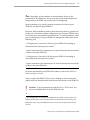
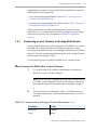
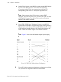
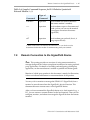
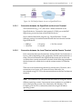
Chapter 1 Installation T he SP201-SA™ is shipped from the factory as a completely integrated system. Only the following installation tasks remain: • Installing the chassis on a tabletop or shelf • Connecting external cables • Powering the system on • Connecting control console equipment • Configuring the system Note: This manual provides detailed instructions for a customized installation of the SP201-SA. It also provides guidelines for maintaining and troubleshooting the SP201-SA. For a quick, standard installation, see the SP201-SA Installation Guide. SP201-SA™ Customization and Maintenance Guide 1-2 Chapter 1: Installation This chapter walks you through the steps to complete the tasks listed above. For this installation, you perform the following tasks: 1.1 1 Unpack, check, and install the SP201-SA on a tabletop. 2 Connect the SP201-SA to the network. 3 Connect the power source and power up the system. 4 Connect the control console. 5 Once the system has been initialized, it is ready for configuration. (See Chapter 2, Configuration Overview.) Safety Precautions Observe the following safety warnings when installing the equipment: • Allow only qualified service personnel to install and maintain this equipment. • To prevent electrical shock, do not power on the equipment until all cables are connected. • Avoid contact with conductors on signaling cables. High voltage may be present. 1.2 Unpacking and Inspecting the Equipment Before you install the SP201-SA chassis, you need to check the equipment carefully to make sure it is not damaged. Carefully remove the unit from the shipping box. Save the box and the packing material in case you need to return damaged equipment. Inspect the equipment for signs of physical damage incurred during shipping. Verify all materials received against the shipping invoice. If the unit or any of its components is damaged, or if any items are missing, file a claim with the shipper and contact Encore Networks, Inc., to obtain a Return Material Authorization (RMA) number. Contact information and detailed return shipping instructions are discussed in the procedure below. Encore Networks is not responsible for items returned without an authorized RMA and reserves the right to reject such returns. SP201-SA™ Customization and Maintenance Guide Unpacking and Inspecting the Equipment 1-3 Once you have determined that the equipment is undamaged, you may install the equipment and connect it to the telephony network. How to Return Damaged or Non-Functioning Equipment or Components via the RMA Process 1 Contact Encore Networks, Inc., at [email protected], 703-318-4350 (voice), or 703-318-4371 (fax) to receive an RMA number. 2 Ensure that all equipment and/or components you are returning are wrapped in packaging material. 3 Ensure that all equipment and/or components you are returning are packed in sturdy containers (preferably the original containers). 4 Clearly mark the RMA number on the outside of the return shipping container(s). 5 Send returns to the following address: Encore Networks, Inc. 45472 Holiday Drive, Suite 3 Dulles, Virginia 20166 U.S.A. Attn: [the RMA number you were given] Note: A copy of the customs invoice must accompany each international shipment. 6 When filling out the shipper’s paperwork, please indicate the contact as “Encore Networks Shipping and Receiving Manager,” and provide Encore’s main telephone number, 703-318-7750. Note: You are responsible for all costs associated with the return (e.g., shipping carrier, customs, etc.). Outside the United States, the costs are for round-trip shipments for all items. Inside the United States, the costs are one-way for warranted items and round-trip for non-warranted items. Unless otherwise specified, Encore Networks, Inc., uses ground transportation for return shipments in the United States, Canada, Mexico, and elsewhere where ground shipment is feasible. If you request a method other than ground shipment, you must pay return SP201-SA™ Customization and Maintenance Guide 1-4 Chapter 1: Installation shipping costs. If you specify another method of shipment, you must specify the courier and provide your customer account number with the courier. International shipments must be door to door. In addition, freight, duties, and taxes must be prepaid for international shipments. We recommend the following freight companies: • United Parcel Service (UPS) (www.ups.com) • FedEx (www.fedex.com) • Airborne Express (www.airborne.com) • DHL Worldwide Express (www.dhl.com) • Emery Worldwide (www.emeryworld.com) Note: In addition to the costs stated above, there may be other charges. The following costs may be incurred during the repair process: • No-Fault-Found Fee: Regardless of the warranty status of the product, a charge will be assessed if there is no fault found with an item returned for repair. A purchase order or pre-payment to cover this charge is required prior to the return of the equipment from Encore Networks to the customer. • Unrepairable-Item Fee: Each unrepairable out-of-warranty item returned for repair is subject to an hourly diagnostic fee, with a two-hour minimum and a four-hour maximum per item. Your purchase order must reflect this understanding. If the item cannot be repaired, you will have the following options: - You may have the equipment returned to you at your expense, in accordance with our policy that the customer is responsible for all shipping costs for out-of-warranty items. - You may send written authorization for us to scrap the item at our site. Either way, our invoice to you will include the diagnostic fee for the unrepairable item. SP201-SA™ Customization and Maintenance Guide Connecting the SP201-SA to the Telephony Network 7 1-5 Ensure that any other paperwork or correspondence you send with the returned equipment reflects the Encore Networks RMA number. Note: Unless otherwise agreed in a purchase order or contract, RMA numbers are valid for thirty (30) days from the date of issuance in the United States, Canada, and Mexico, and for sixty (60) days in all other countries. If Encore Networks does not receive the equipment to which the RMA number has been assigned within the valid time frame, the RMA will be closed. Regardless of warranty status, if equipment bearing this RMA number is received after the time frame closes, it may be refused or there may be a charge for repair. 1.3 Connecting the SP201-SA to the Telephony Network The trunk ports (DS1s) are the physical interfaces through which the external network user equipment communicates with the SP201-SA. On the two-port SP201-SA (Figure 1-1), port 1 carries one signaling protocol and port 2 carries another signaling protocol. Port 1 allows a choice of connector interface. Figure 1-1. Rear View of Two-Port SP201-SA Chassis On the four-port SP201-SA (Figure 1-2), ports 1 and 2 carry one signaling protocol and ports 3 and 4 carry another signaling protocol. Ports 1 and 3 allow a choice of connector interface. Figure 1-2. Rear View of Four-Port SP201-SA Chassis SP201-SA™ Customization and Maintenance Guide 1-6 Chapter 1: Installation Table 1-1, describing the ports on the SP201-SA models, reflects the following port correspondence: • Port 1 of the two-port SP201-SA corresponds to port 1 of the four-port SP201-SA. • Port 2 of the two-port SP201-SA corresponds to port 3 of the four-port SP201-SA. Table 1-1. SP201-SA Port Interfaces Two-Port SP201-SA Four-Port SP201-SA Port Description Port Description 1 2 Choice of: 1 Choice of: • One RJ-48C connector for a T1 100-ohm balanced trunk or an E1 120-ohm balanced trunk • One RJ-48C connector, for a T1 100-ohm balanced trunk or an E1 120-ohm balanced trunk • Two BNC ports for E1 75-ohm unbalanced Receive and Transmit connections1 • Two BNC ports for E1 75-ohm unbalanced Receive and Transmit connections1 One RJ-48C connector for a T1 100-ohm balanced trunk or for an E1 120-ohm balanced trunk 2 One RJ-48C connector for a T1 100-ohm balanced trunk or for an E1 120-ohm balanced trunk 3 Choice of: • One RJ-48C connector, for a T1 100-ohm balanced trunk or an E1 120-ohm balanced trunk • Two BNC ports for E1 75-ohm unbalanced Receive and Transmit connections1 4 One RJ-48C connector for a T1 100-ohm balanced trunk or for an E1 120-ohm balanced trunk 1. Each BNC port has two connectors: one for Receive and one for Transmit. SP201-SA™ Customization and Maintenance Guide Connecting the SP201-SA to the Telephony Network 1-7 Note: Regardless of port numbers or trunk numbers shown in the procedures in this document, always type the port or trunk number that corresponds to the SP201-SA port that you are configuring. Some procedures may specify separate instructions for the two-port SP201-SA and the four-port SP201-SA. However, other procedures need to show the more extensive, general case. In this case, instructions explain configuration of a four-port SP201-SA that has all four ports connected to network devices.1 In such procedures, when you are configuring a two-port SP201-SA, interpret the instructions in the following way: • Configure port 1 (or trunk 1) of the two-port SP201-SA according to instructions that mention port or trunk 1. • Ignore instructions that mention port or trunk 2 (because the instructions assume a four-port SP201-SA). • Configure port 2 (or trunk 2) of the two-port SP201-SA according to instructions that mention port or trunk 3. • Ignore instructions that mention port or trunk 4 (because the instructions assume a four-port SP201-SA). For more information on the SP201-SA hardware, refer to the SP201-SA Hardware Reference Guide. After you place the SP201-SA chassis on a tabletop or shelf, connect the digital trunk line interface cables from the network devices to the SP201-SA. ! Caution: To ensure compliance with the Class A FCC Limits, you must use shielded cables with the SP201-SA unit. 1. The configuration of your four-port SP201-SA may differ. You do not have to connect all four ports, even if the procedures list instructions for all four ports. Both ports of the two-port SP201-SA must, of course, be connected to network devices. SP201-SA™ Customization and Maintenance Guide 1-8 1.4 Chapter 1: Installation Connecting to the Power Source The SP201-SA unit has one external power supply. The external power supply receives input from a power source of 110 to 220 volts AC at 50 to 60 Hz. (The AC power supply autosenses the AC voltage.) The power supply outputs 5.5 volts DC to the SP201-SA. After completing all other connections, you can connect the SP201-SA to the power source. How to Connect the SP201-SA to the Power Source 1 Make sure the SP201-SA’s external power supply is not currently connected to a power source. 2 Connect a (minimum) 12 AWG wire to the large earth ground screw located below the safety ground symbol on the rear of the SP201-SA chassis. Use a ring terminal, such as an AMP (part number 36160) for this connection. Warning: An earth ground must connect to the SP201-SA chassis itself so that the chassis remains grounded even when the power connection is removed. 3 Connect the external power supply to the SP201-SA’s power supply interface. 4 Connect an AC power cord to the external power supply’s AC connector. (The power cord is shipped to destinations within North America. Outside North America, contact your local distributor for the proper power cord.) 5 Plug the power cord into a power outlet. The SP201-SA powers on. 1.5 Connecting to the Control Console You must connect a control console (for example, a personal computer) to the SP201-SA. The connection to the control console lets you configure the SP201-SA and maintain it once it is operational. (The control console is SP201-SA™ Customization and Maintenance Guide Connecting to the Control Console 1-9 supplied by the customer.) Use one of the following methods to connect a control terminal to the SignalPath: • Use a direct connection described in Section 1.5.1, Connecting a Local Terminal to the SignalPath Device. • Connect over a remote modem, described in Section 1.5.2, Connecting an External Modem to the SignalPath Device. After communication has been established and the system has been initialized, you use a command line interface to configure system features and provision services. This is described in Chapter 2, Configuration Overview. 1.5.1 Connecting a Local Terminal to the SignalPath Device You use the RJ45 Supervisory port on the front of the SP201-SA to connect the SP201-SA to the control console. The RJ45 port provides a direct connection to the SP201-SA from a non-intelligent ASCII terminal (VT100) or from a PC that uses a terminal-emulation program, such as HyperTerminal. (Set the terminal to emulate VT100.) Use the following steps to connect the SP201-SA to a control console. How to Connect the SP201-SA to a Control Terminal 1 Use an RJ45 cable, with an RJ45-to-DB9 adapter, to connect the SP201-SA to your PC’s DB9 COM port. Note: If you are using a computer terminal with a universal serial bus (USB), you must provide a serial-to-USB adapter. (Contact the manufacturer of the USB for information on the proper adapter.) 2 Set the parameters as indicated in Table 1-2. (For information on setting these parameters, consult the documentation for your PC or terminal.) Table 1-2. Communication Settings for Terminal Emulation (1 of 2) Parameter Value Baud rate 9600 bps Parity None SP201-SA™ Customization and Maintenance Guide 1-10 Chapter 1: Installation Table 1-2. Communication Settings for Terminal Emulation (2 of 2) Parameter Value Data bits 8 Stop bit 1 Flow control None 3 Save and re-open the configuration. Communication between the SP201-SA and the control console is established when you open the saved configuration. 4 Next, type warmstart and press Enter. The SP201-SA will reboot. Note: If there is no readout on the control console, communication with the SP201-SA has not been established. In this case, perform Step 2 through Step 4 again. If necessary, unplug the SP201-SA’s power supply and then plug it in again. If this does not work, contact Technical Support. 1.5.2 Connecting an External Modem to the SignalPath Device You may wish to connect an external modem to a SignalPath device so that you can manage the SignalPath from another location. Note: You must configure each modem from a terminal (such as a PC using terminal emulation software). You cannot configure the modem through the SignalPath. After configuring the modems, connect the remote modem to the SignalPath. How to Configure and Connect an External Modem to the SignalPath 1 On the local side, use a serial RS232 straight-through female-DB9-tomale-DB25 cable to connect a local external modem to the control terminal’s DB9 COM port. SP201-SA™ Customization and Maintenance Guide Connecting to the Control Console 1-11 2 On the remote side, use a serial RS232 straight-through female-DB9to-male-DB25 cable to connect an external modem to the temporary control terminal’s DB9 COM port. 3 Set the following mandatory modem setup requirements. Mandatory Modem Setup Requirements • Auto Answer • Serial Port data rate must be fixed at 9600 bps • Data Terminal Ready (DTR) must be ignored or overridden • Flow control must be disabled • Data Compression must be disabled • Error control must be disabled • Connect speed must be set to 9600 bps • Command echo must be disabled • Result codes must be suppressed Note: To set the external modem up, use the modem’s physical switches and/or software commands, as indicated in the modem manufacturer’s instructions. Section 1.5.2.1, Sample Settings for an External Modem, provides one example of switches used for modem setup and software commands used for modem configuration. 4 Configure each modem for communication across the network. Note: You may need to temporarily change the modem’s settings so that you can configure it. Then, for operation, set the switches back to the mandatory modem setup requirements. 5 After the modems have been configured, you need to connect the remote modem to a SignalPath device. Disconnect the remote terminal from the remote modem. Then do one of the following for the remote modem: SP201-SA™ Customization and Maintenance Guide 1-12 Chapter 1: Installation a On the SP230: Connect a serial RS232 straight-through DB25 cable to the CCI's male DB25 connector and to the external modem. (Connection to the CCI lets you communicate with the CCI’s corresponding SCM. The CCI’s serial port is physical DCE.) Note: Older versions of the CCI may have a female DB25 connector, physical DTE. In this case, one end of the cable will need a DB25 gender changer. The cable will also need a null modem adapter at the modem connector. b On an SP201, SP201-SA, or R2Adapter: Connect a serial RS232 female-DB9-to-male-DB25 straight-through cable to the SignalPath's DB9 connector and to the external modem’s DB25 connector. Attach a DB9 male-male gender changer at the SignalPath connector, and attach a DB25 null modem adapter at the modem connector. Note: Figure 1-3 shows the null modem adapter’s pin mapping. Figure 1-3. DB25 Null Modem Adapter Pin Mapping 6 Use an RJ11 cable to connect each modem to a telephone jack. Make sure you know the telephone number for each modem. SP201-SA™ Customization and Maintenance Guide Connecting to the Control Console 7 1.5.2.1 1-13 At the local terminal, use the local modem to dial the remote modem’s number. When the remote modem answers, configure or manage the remote SignalPath device. Sample Settings for an External Modem This section provides settings for one type of external modem, the U.S. Robotics Sportster®. Also see Section 1.5.2.2, Sample Command Sequence for an External Modem. Table 1-3. DIP Switch Settings for U.S. Robotics Sportster® External Modem Switch Setting Definition 1 down Data terminal ready override 2 up Verbal result codes 3 up Suppress result codes 4 down No echo, offline commands 5 up Auto answer on first ring (or higher, if specified in NVRAM) 6 up Carrier detect normal 7 up Load configuration profile from NVRAM 8 down Smart mode Table 1-4. Sample Profile Setup Commands for U.S. Robotics Sportster® External Modem Command Description at command prefix for modem’s attention—e.g., ATH y0 user profile 0 setting in NVRAM &w0 writes (saves) current setting to profile 0 in NVRAM i4 displays current settings i5 display profiles in NVRAM dt dial, using dual tone (touch tone) +++ switch to modem command mode h hang up modem SP201-SA™ Customization and Maintenance Guide 1-14 Chapter 1: Installation Table 1-5. Sample Extended Data Commands for U.S. Robotics Sportster® External Modem 1.5.2.2 Command Description &b1 serial port data rate fixed &h0 flow control disabled &k0 data compression disabled &m0 error control disabled &n6 connect speed fixed at 9600 bps Sample Command Sequence for an External Modem Table 1-6 lists a partial command sequence as an example of using the modem connection to dial into and configure a remote SignalPath. Use a terminal (or a PC in terminal emulator mode) to connect to the local modem. Note: Only one person at a time can communicate with an SP201-SA. Table 1-6. Sample Command Sequence for U.S. Robotics Sportster® External Modem (1 of 2) Command Type of Command Action at test Local modem responds with “ok.” at &b1 or at&b1 configuration Local modem’s serial port rate is fixed. (spaces do not matter) ... at i4 configuration Local modem lists its current settings. at &w0 configuration Local modem writes (saves) its current configuration in profile 0. If necessary, change the modem’s settings from configuration to operation. SP201-SA™ Customization and Maintenance Guide Remote Connection to the SignalPath Device 1-15 Table 1-6. Sample Command Sequence for U.S. Robotics Sportster® External Modem (2 of 2) Command Type of Command at dt 4353 operation Local modem uses tones to dial 4353 (the remote modem’s number). +++ operation Local modem escapes to line-command mode (so that you can use the terminal to configure or monitor the remote SignalPath). operation Local modem goes on hook (that is, it hangs up on the call). Action ... ath1 1. When result codes are enabled, the command ath can also be used to determine whether the modem is communicating with your terminal. 1.6 Remote Connection to the SignalPath Device Note: This section provides an overview of using remote terminals to manage the SignalPath. It does not replicate instructions for setting up thirdparty applications. For details of installing and configuring a third-party application, see the manufacturer’s website or product installation guide. Mention of a third-party product in this document is merely for illustration; it does not indicate endorsement or recommendation of the product. You may wish to monitor or manage the SP201-SA™ (SignalPath) from a terminal at some distance from the SignalPath’s physical location. This document discusses remote access to the SignalPath device. After you have connected the SignalPath device to its local terminal (e.g., a PC), you can connect a remote terminal to the local terminal. Then you can configure, monitor, and otherwise manage the SignalPath from the remote terminal. SP201-SA™ Customization and Maintenance Guide 1-16 Chapter 1: Installation Note: The SP201-SA does not have an IP address; however, it has a direct serial connection to a local terminal. If the local terminal has an IP address and you wish to use a remote terminal to communicate with the SignalPath, you must connect the remote terminal to the SignalPath’s local terminal. 1.6.1 Sample Connections and Products The following are typical connections between the local and remote terminals: • Virtual private network (VPN), using the Point-to-Point Tunneling Protocol (PPTP). PPTP VPN is available in Microsoft Windows 98 and above. • Virtual network computing (VNC) • Telnet protocol, through a VPN tunnel. After connection, the remote terminal can use its copy of a terminal-emulation program (e.g., HyperTerminal) to manage the SignalPath device. There are many products that can be used for remote access to the SignalPath’s local terminal. The following are some products available for remote access (with URLs for product information): 1.6.2 • NetMeeting www.microsoft.com/windows/netmeeting • pcAnywhere www.symantec.com/pcanywhere • RealVNC www.realvnc.com • Yahoo! Messenger messenger.yahoo.com Connection Overview Remote access to the SignalPath device has two components, as shown in Figure 1-4: the connection between the SignalPath and its local terminal, and the connection between the local terminal and the remote terminal. SP201-SA™ Customization and Maintenance Guide Remote Connection to the SignalPath Device 1-17 Figure 1-4. Full Path for Remote Access to a SignalPath Device 1.6.2.1 Connection between the SignalPath and the Local Terminal The local terminal (e.g., a PC) must have a direct connection to the SignalPath device. Connect the local terminal’s COM1 port to the RJ45 Supervisory port on the front of the SP201-SA chassis. Start a terminal-emulation program (e.g., HyperTerminal). Use the following settings for communication between the local terminal and the SignalPath device: • 9600 bps • 8 data bits 1.6.2.2 • No parity • 1 stop bit • No flow control Connection between the Local Terminal and the Remote Terminal In the connection between the terminals, the SignalPath’s local terminal is a host or a client (depending on the application), and the remote terminal is a client. The unit connected to the SignalPath device must be on line and available when a remote connection is desired. (In the following procedures, the local terminal is called the host and the remote terminal is called the client.) There are several connection protocols for remote access. However, most connections travel across an IP network. Encore Networks, Inc., recommends using TCP/IP for the connection between the local and remote terminals. Note: The connection can take place between terminals using the same or different operating systems. Some remote-access products are available in each of the operating systems Unix, Macintosh, and Windows. The examples given are for a workstation (terminal) using the Windows operating system. SP201-SA™ Customization and Maintenance Guide 1-18 Chapter 1: Installation The following general instructions indicate the overall process: • On the host workstation, set up an account for the client. • On the client workstation, configure the information for connection to the host. The following items are common to all connections: • Each workstation must enable a remote desktop connection. (This feature is available in Windows 2000 and above.) • Each workstation must install the software needed for the connection. • In general, you will need to set the following information for the connection between the PCs. (Details vary by product.) - The host and the client must indicate connection type, workstation names or IP addresses, passwords, etc. (Except for items specific to the client, configuration values depend on the host.) - The host must set permissions, levels of access, firewall opening, etc., for the client connection. Note: The method of letting a connection penetrate a firewall depends on the firewall. Get this information from your network administrator. (Basic firewalls on home systems typically cannot specify items; the firewall itself must be turned off, thereby affording no protection. However, some homeoffice firewall products may let you specify IP addresses or machine names to let through. Check with a firewall product’s manufacturer before purchasing the product.) At connection, the host challenges and authenticates the client (if you have configured the connection for challenge and authentication). After the connection has been established, the client can use the host workstation to manage the SignalPath device. Note: A connection’s security depends on the product. Some products might not of themselves provide secure connections and might advise tunneling the connection through a secure-connection protocol such as VPN or Secure Shell (SSH). See the product manufacturer’s website for information. SP201-SA™ Customization and Maintenance Guide Remote Connection to the SignalPath Device 1-19 Note: Some products include a webserver so that clients can use a browser for remote management. The same process is used to establish the connection: The host must set up a client account, etc. 1.6.3 Sample Connection This guide uses the commercial product pcAnywhere to illustrate configuration of a remote connection. In pcAnywhere, the PC connected to the SignalPath device is a host. The host and the client are configured in similar ways in pcAnywhere. Before configuring, determine the information (IP address, etc.) for each side of the connection. Note: One licensed copy of pcAnywhere must be on each PC. Other products may use a different distribution of software. See the manufacturer’s requirements for licensed use of a software package. Configure the host in the following way: • In Windows, enable remote access. • Open pcAnywhere and select the menu button Be a Host PC. • In the pcAnywhere window, select the icon for Add a Host PC Item. • When prompted, enter the host’s name for the connection. • When prompted, select TCP/IP connection. • In the subsequent prompt window, uncheck Automatically launch session upon wizard completion. • After the connection setup has finished, right-click the icon for the connection. (The icon shows the connection name.) Then select Properties. • Select the Callers tab. Then check Specify individual caller privileges, select the Add Caller icon, and enter the client information, including password. SP201-SA™ Customization and Maintenance Guide 1-20 Chapter 1: Installation • After the client setup has finished, right-click the icon for the client and select Properties. Then select the Advanced tab and specify the client’s privileges on the host machine. • In the host’s firewall software, indicate that the client connection may pass through the firewall. (Consult your network administrator for information on doing this.) Configure the client in the following way: • In Windows, enable remote access. • Open pcAnywhere and select the menu button Remote Control. (This indicates that this machine will be a client in the connection.) • In the pcAnywhere window, select the icon Add Remote Control Item. • When prompted, enter the client’s name for the connection. • When prompted, select TCP/IP connection. • On the same screen, enter the host name or the IP address the host has provided. (The host may have masked its private IP address, providing only its public IP address.) • In the subsequent prompt window, uncheck Automatically begin session upon wizard completion. • After the connection setup has finished, right-click the icon for the connection. (The icon shows the connection name.) Then select Properties. • Select the Connection Info tab and select the Details button. Then indicate whether the connection goes through a gateway. (This depends on the host’s network.) After you have configured the host and the client, the client’s administrator may still need the password from the host’s administrator. Then the client can connect to the host and manage the SignalPath device. SP201-SA™ Customization and Maintenance Guide