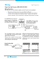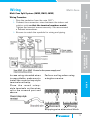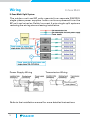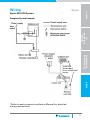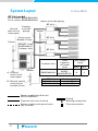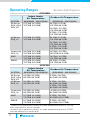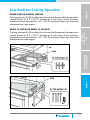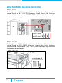
1
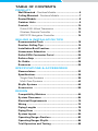
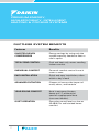
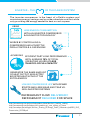
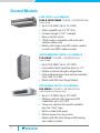
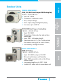
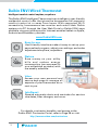
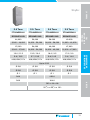
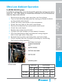
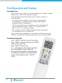
DUCTLESS PRODUCTS REFERENCE GUIDE DAIKIN: THE PREMIUM BRAND INDUSTRY LEADER Daikin Industries, Ltd. (DIL) is a global Fortune 1,000 company which celebrated its 90th anniversary in May 2014. The company is recognized as the largest HVAC (Heating, Ventilating, Air Conditioning) manufacturer in the world. Daikin is primarily engaged in developing indoor comfort products and systems and refrigeration products for residential, commercial and industrial applications. Its consistent success is derived, in part, from a focus on innovative, energy-efficient and premium quality indoor climate and comfort management solutions. KE Series *Complete warranty details available from your local dealer or at www.daikincomfort.com and www.daikinac.com. To receive the 10-Year Parts Limited Warranty, online registration must be completed within 60 days of installation. Online registration is not required in California or Quebec. LV Series, Quaternity & MXS Multi-Zone Complete warranty details available from your local dealer or w w w.daikincomfor t.com and w w w.daikinac.com. To receive the 12-Year Parts Limited Warranty, online registration must be completed within 60 days of installation. Online registration is not required in California or Quebec. SkyAir (Light Commercial) †Complete warranty details available from your local dealer or w w w.daikincomfor t.com and www.daikinac.com. † TABLE OF CONTENTS PRODUCT Wall Mounted - Ductless Models....................................6 Ceiling Mounted - Ductless Models...............................7 Ducted Models ................................................................8 Outdoor Units .................................................................9 Controls .........................................................................10 Daikin ENVi Wired Thermostat ....................................10 Wireless Remote Controller .........................................12 BRC1E72 Navigation Controller....................................14 SELLING & INSTALLATION TIPS Recommended Tools ...................................................18 Ductless Selling Tips ...................................................19 Installation Best Practices ..........................................21 Homeowner Education ................................................23 Daikin ENVi Contractor Portal ....................................26 Daikin eQuip ..................................................................27 Dr. Daikin .......................................................................28 Resources.......................................................................29 SPECIFICATIONS & ACCESSORIES Nomenclature ...............................................................32 Specifications ...............................................................36 Single-Zone Systems ...................................................36 Multi-Zone Systems .....................................................42 SkyAir Systems ............................................................46 Accessories ...................................................................56 DESIGN Compatibility Matrices ................................................60 System Clearances .......................................................64 Electrical Requirements ..............................................70 Wiring .............................................................................72 Piping Lengths ..............................................................76 Piping Sizes ...................................................................78 System Layout...............................................................80 Operating Ranges Ductless.........................................82 Operating Ranges SkyAir.............................................86 Trial Operation and Testing.........................................88 PREMIUM-ENERGY, HIGH-EFFICIENCY, INTELLIGENT HEATING & COOLING SYSTEMS DUCTLESS SYSTEM BENEFITS 2 Features Benefits INVERTER-DRIVEN COMPRESSORS Energy savings by using only the system capacity needed to heat or cool a space TOTAL ZONE CONTROL Cool and heat only rooms needing indoor comfort INDIVIDUAL COMFORT Personal comfort control in each room or zone EASY INSTALLATION Quick and easy installation, often within a day’s work ADVANCED FILTRATION Cleaner air lessens the impact of mold, odors, and bacteria YEAR-ROUND COMFORT Heat in extreme climates, down to-4° F, without the need of supplemental heat (on some models). QUIET OPERATION Operating sound levels as low as 22 dB(A) for undisturbed home comfort. INVERTER – THE OF THE DAIKIN SYSTEM The inverter compressor is the heart of a Daikin system and maximizes energy savings and provides absolute comfort while only providing the energy needed to heat or cool a space. USING LESS ENERGY CONSUMPTION WITH AN INVERTER COMPRESSOR & FAN MOTOR TECHNOLOGY WORKS BY CONTROLLING A COMPRESSOR LIKE A THROTTLE PEDAL CONTROLS A CAR ENGINE ACHIEVING 75% EFFICIENT PART LOAD PERFORMANCE WITH AVERAGE 75% OF TOTAL OPERATING HOURS AT LESS THAN 70% OF FULL CAPACITY GENERATES THE SAME AMOUNT OF HEAT OUTPUT AS ELECTRIC BOOSTER HEAT WITHOUT THE EXTRA ENERGY LONGER COMPRESSOR LIFE WITH FEWER STARTS AND LESS WEAR AND TEAR VS. NON-INVERTER SYSTEMS REFRIGERANT FLOW DELIVERED = REFRIGERANT REQUIRED FOR SPACE http://www.energystar.gov/certified-products/detail/ductless_heating_cooling http://www.energystar.gov/index.cfm?c=products.pr_save_energy_at_home http://www.bpa.gov/energy/n/Utilities_Sharing_EE/Energy_Smart_Awareness/pdf/BPA_DHP_ Presentation_022708.pdf 3 PRODUCT Wall-Mounted Ductless Models KE SERIES | 9,000 - 24,000 BTU/h Heat Pump or Cooling Only §§ §§ §§ §§ Up to 18 SEER | Up to 8.5 HSPF Quiet operation as low as 22 dB(A) Low ambient heat operation down to 0°F* Energy savings at an affordable cost LV SERIES | 9,000 - 36,000 BTU/h Heat Pump or Cooling Only** §§ §§ §§ §§ §§ Up to 24.5 SEER | Up to 12.5 HSPF Intelligent Eye occupancy sensor Weekly timer for programmable comfort Low ambient heat operation down to 0°F* Low ambient cooling kit available QUATERNITY | 9,000 - 15,000 BTU/h Heat Pump §§ §§ §§ §§ Up to 26.1 SEER | Up to 11.0 HSPF Low ambient heating operation down to -4°F Dehumidifying to a preset relative setting Integrated air cleaner for advanced filtration for allergens, odors, and bacteria FAQ / FTXS SERIES | 18,000 - 36,000 BTU/h Heat Pump or Cooling Only §§ Up to 18.6 SEER | Up to 8.7 HSPF §§ Vertical auto-swing function ensures efficient air distribution §§ Removable front panel for easy cleaning §§ Mold-resistant, washable filters *with optional wind baffle **On select models 6 PRODUCT Ceiling-Mounted Ductless Models 2’ X 2’ CEILING CASSETTE FFQ SERIES | 9,000 – 18,000 BTU/h Heat Pump 2, 3 or 4-way airflow pattern Built-in condensate pump (up to 22”) Fresh air intake knockout Match with multi-split MXS outdoor models only SELLING & INSTALLATION TIPS §§ §§ §§ §§ SKYAIR ROUNDFLOW CASSETTE FCQ SERIES | 18,000 – 42,000 BTU/h Heat Pump or Cooling Only SPECIFICATIONS & ACCESSORIES §§ Up to 17.5 SEER | up to 10.1 HSPF §§ 23 configurable airflow patterns ensure ideal airflow distribution §§ 360° airflow reduces draft §§ Stain-resistant decoration panel allows for easy cleaning §§ Match with RZQ Heat Pump or RZR cooling only outdoor models SKYAIR CEILING SUSPENDED FHQ SERIES | 18,000 – 42,000 BTU/h DESIGN Heat Pump or Cooling Only §§ Up to 18.0 SEER | up to 11.1 HSPF §§ Auto-swing capability with 100° airflow pattern for comfortable distribution §§ Lateral servicing space allows installation in corners, narrow spaces, walls, and ceilings §§ Innovative stream fan technology §§ Match with RZQ Heat Pump or RZR cooling only outdoor models 7 Ducted Models LOW-STATIC (< 0.2) MODELS FDXS & CDXS SERIES | 9,000 – 24,000 BTU/h Heat Pump §§ §§ §§ §§ §§ Up to 15.5 SEER | Up to 10.4 HSPF Static capability up to 0.16" W.G. Compact design (7-7/8" in height) Rear or bottom return CDXS models compatible with multi-split outdoor models only §§ Match with single zone RXS outdoor models or multi-zone MXS outdoor models SKYAIR MEDIUM-STATIC (< 0.5) MODELS FTQ SERIES | 18,000 – 42,000 BTU/h Heat Pump §§ §§ §§ §§ Up to 20.0 SEER | Up to 12.0 HSPF Low ambient heat operation down to -4°F Upflow or horizontal right configurations Field-installed electric heat options available from 3 kW to 15 kW §§ Match with RZQ Heat Pump Models SKYAIR HIGH-STATIC (< 0.8) MODELS FBQ SERIES | 18,000 – 42,000 BTU/h Heat Pump or Cooling Only §§ Up to 17.5 SEER | Up to 10.6 HSPF §§ Medium external static pressure (ESP) capabilities up to 0.8" W.G. §§ Three user selected fan speeds available plus fan “Auto” logic §§ Built-in condensate pump §§ Bottom access for easy service §§ Match with RZQ Heat Pump or RZR cooling only outdoor models 8 PRODUCT Outdoor Units SINGLE-ZONE MODELS RXN, RXS, RXG Heat Pump or RKN Cooling Only 9,000 – 24,000 BTU/h Up to 26.1 SEER Available in 4 different models Slim, compact design 33 ft. of pre-charged refrigerant piping For rooms up to 1,600 SF SELLING & INSTALLATION TIPS §§ §§ §§ §§ §§ RXS & RZQ Heat Pump or Cooling Only 18,000 – 42,000 BTU/h SPECIFICATIONS & ACCESSORIES §§ Up to 20.0 SEER §§ Choose from 6 indoor ducted and ductless model types §§ Up to 230 ft. total piping length §§ Operation down to 0°F (-40°F with optional low ambient cooling kit on select models) §§ User-friendly, intelligent controls MULTI-ZONE MODELS MXS Heat Pump 18,000 – 48,000 BTU/h DESIGN §§ Up to 19.5 SEER and up to 9.5 HSPF §§ Mix and match indoor unit flexibility §§ Up to 130% connection ratio on the 8-Zone outdoor model §§ Long piping lengths up to 433 ft. total §§ Connect 2-8 indoor units to one outdoor unit 9 Daikin ENVi Wired Thermostat Intelligent comfort control anytime, anywhere The Daikin ENVi Intelligent Thermostat is an intelligent, user-friendly residential control offer that gives the homeowner full access to comfort control at or away from home. With supported Wi-Fi connectivity, homeowners can monitor and control their Daikin systems via PC through the User Web Portal or Daikin ENVi apps available via smart phone and/or Internet-enabled tablet on Apple, Android and Blackberry devices. www.DaikinENVi.com Easy-to-use User-friendly interface makes it easy to set up your personalized program, adjust your settings, and make adjustments anytime, anywhere. Nature Save money on your utility b ill s a n d r e d u c e e n e r g y consumption (as compared to non-scheduled systems) with the weekly schedule. Value Access your own personal and secure web page to manage all aspects of your thermostat at no cost to you. Intelligent Receive automatic alerts and reminders for service due dates, filter changes, and more. 12 10 For details, contractor benefits, and access to the Daikin ENVi Contractor Portal, refer to Page 26 or visit http://www.ecobee.com/contractors Operation Navigation Mode Button SELLING & INSTALLATION TIPS Current Date and Time PRODUCT DACA-TS1-1 SPECIFICATIONS & ACCESSORIES Menu Options Current Set Point Current Temperature and Humidity Features Include: Wi-Fi enabled for access anywhere via smart phone, tablet, or computer Weekly schedule Live weather forecasts Automated alerts and reminders Cool, heat, and auto modes with dual set point control Setback control Room temperature and relative humidity display DESIGN §§ §§ §§ §§ §§ §§ §§ 13 11 Wireless Remote Controller Comfort control at your fingertips Want to make your room comfortable at the touch of a single button? No problem. Wall-mounted and slim-ducted units come with a user-friendly remote control featuring a minimalistic, modern design in a matte crystal-white finish that forms a perfect match with the indoor unit. CONTROLLER FEATURES INCLUDE: §§ FAN: Fan speed adjustment §§ POWERFUL: System boost for 20 minutes in current operating mode §§ MODE: HEAT, COOL, AUTO, DRY §§ TEMP: Setpoint adjustment §§ COMFORT*: Adjusts louver position based on mode §§ SENSOR*: Intelligent Eye occupancy sensor §§ SWING*: Automatic vertical and horizontal auto-swing §§ WEEKLY*: 7-day programmable schedule §§ TIMER: Timer and clock adjustment *Available on Select Systems 12 PRODUCT SELLING & INSTALLATION TIPS Fan Speed Temperature Powerful Operation Cancel Timer Timer On Timer/Clock Optional wall-mounted wired controller (BRC944B2) available (requires KRP adapter on the 09,12 KE models) DESIGN Timer Off Vertical Auto Swing Horizontal Auto Swing Schedule Copy SPECIFICATIONS & ACCESSORIES Operation Mode Outdoor Quiet Operation Weekly Timer Temperature 15 13 BRC1E72 Navigation Controller Advanced, configurable comfort. The Navigation Controller provides advanced comfort with as little or as much control as your home or business desires. Choose from an advanced or simplified display or one of the available optional face decals for comfort in a minimal, sleek design. Advanced Display Simplified Display Optional Face Decals Single Setpoint Face Decals for Simplified Display BRC1E72RM BRC1E72RF BRC1E72RMF Dual Setpoint Face Decals for Simplified Display 14 BRC1E72RM2 BRC1E72RF2 BRC1E72RMF2 Basic Operation Operation Mode Function Configurable Display Set Point Auto-Changeover Fan Speed, Airflow Direction Weekly Schedule Auto On/Off Timer Independent Cooling and Heating Set Points and Setback for unoccupied periods Fan Speed Room Temp Current Date/Time SPECIFICATIONS & ACCESSORIES Operation Mode SELLING & INSTALLATION TIPS PRODUCT Features & Functions: Set point Backlit Display On/Off Menu/OK Operation Mode Selector DESIGN Cancel Menu Navigation Control Fan Speed Control 15 SELLING & INSTALLATION TIPS Recommended Installation Tools Make sure to use installation tools that are exclusively used for R-410A installations to withstand the pressure and to prevent foreign materials from mixing into the system. ££ 1/4"- 5/8" Torque Wrench ££ Adjustable Wrenches ££ Charge Hose ££ Deburring Tool ££ Flare Gauge Set ££ Flaring Block ££ Gauge Manifold ££ Nitrogen ££ Phillips Screwdriver ££ Tubing Cutter ££ Vacuum Pump 18 SELLING & INSTALLATION TIPS PRODUCT Ductless Selling Tips Look for opportunities to sell Daikin Ductless systems on EVERY call. SPECIFICATIONS & ACCESSORIES 1. Discover homeowner problems and needs. Ask questions and have customers fill out a comfort survey prior to or during the visit. ££ Lifestyle – age of home, family members in home, main living areas (bedroom, living room), remodeling, etc. ££ Comfort – airflow issues, hot or cold rooms, noise issues, air quality, etc. ££ Energy – average energy bills, expected utility trends, energy improvements to home, etc. DESIGN 2. Look for additional comfort and energy saving opportunities throughout the home. ££ Areas with heavy or low sunlight ££ Empty rooms ££ Space heaters or portable air conditioners ££ Air filtration devices ££ Sunrooms, porches, basements, attics, additions 19 3. Introduce Daikin Ductless systems features and benefits. ££ Next generation heating and cooling ££ Ductless and ducted system options for individual rooms or entire homes ££ Maximum energy efficiency ££ Heat and cool only the rooms you use ££ Individual room comfort control ££ Long-life, washable filters with allergen filtration ££ Quick and easy installation ££ High quality, reliable products with outstanding warranties* 4. Introduce the benefits of Daikin ENVi Intelligent Thermostats. ££ Control remotely from anywhere using PC, smart phone or tablet ££ Traditional thermostat functionality ££ Bright, backlit display ££ View room temperature, relative humidity, outdoor temperature and weather forecast 5. Include Daikin Ductless system options with your proposal and differentiate from the competition. ££ Go beyond traditional ductless systems and offer more comfort choices ££ Recommend an option that includes a Daikin system ££ Provide your customers with superior comfort, control and efficiency *Complete warranty details available from you Daikin distributor. 20 PRODUCT Ductless Installation Best Practices Outdoor Unit (Compressor) SELLING & INSTALLATION TIPS §§ Locate the outdoor unit on a stable level surface solid enough to bear the weight and potential vibration of the unit. §§ Use adjustment risers to place the unit off the ground to minimize debris and snow buildup and improve drainage. Do not place anything under the unit which must be kept away from moisture. §§ Secure outdoor units to pads, risers and/or surface using bolts and/or adhesives. Condensate Drain SPECIFICATIONS & ACCESSORIES §§ Install with a downhill slope. Drain may be routed with line set and run to a proper termination point so long as it is away from crawl spaces and walkways. Refrigerant Charge DESIGN §§ Ensure the system has the proper refrigerant charge. Many installations may not require adjustments. §§ Gauges to verify refrigerant levels are only needed when adjustments are necessary. A scale must be used to ensure a proper charge when adding or removing refrigerant. Properly installed Daikin systems can provide: §§Reduced callbacks and improved profitability §§Valuable energy savings for your customers §§Improved customer satisfaction §§Increased referrals and future sales 21 Attend a Daikin University course for more information. Register online at www.DaikinUniversity.com Line Set Insulation and Protection §§ Cover the entire line set length with insulation to avoid condensation. Refer to installation manual for proper insulation dimensions. §§ Use separate thermal insulation pipes for gas and liquid refrigerant pipes. §§ Use line cover to protect the outdoor portion of the insulated line set to avoid premature insulation damage. §§ Add UV tape as needed on areas without line cover to ensure protection of the entire line set length. Cold Climate Efficiency and Installation Tips Indoors §§ Furnaces or Zonal Electric Heat – Set back at the thermostat or shut off at the breaker for furnace or zonal heat so that it does not compete with the Daikin system. §§ Temperature Set Back – Set programmable thermostat to HEAT with the fan in ON position for air distribution and set the temperature 4° F below the Daikin system. Outdoors §§ Increase clearance under the outdoor unit to promote easy drainage and reduce snow and ice buildup. §§ Consider wall-mount brackets to increase outdoor unit clearance. §§ Use a pan heater to avoid defrost discharge freezing inside the condenser in extreme climates. 22 SELLING & INSTALLATION TIPS PRODUCT Homeowner Education SPECIFICATIONS & ACCESSORIES §§ Use Daikin systems as the primary heating and cooling system to increase comfort and efficiency. Secondary heating and cooling systems can remain off until needed as a supplement. §§ Regular washing and cleaning of the filters can maintain performance and efficiency of Daikin ductless systems. §§ Familiarize customers with all features provided on the Remote functionality, please see the Controller Quick User Guides: §§ BRC944B2 Controller Quick User Guide §§ ARC433 A51/A53/A63 Controller Quick User Guide §§ ARC447A3 Quaternity Controller Quick User Guide DESIGN continued on next page 23 §§ Introduce the features of Daikin ENVi Intelligent Thermostats. §§ Wi-Fi set-up §§ PC, smart phone, tablet control §§ System control and scheduling §§ Outside temperature, humidity and weather forecasts §§ Explain temperature control from remote controller, set temperature setpoints that provide the desired comfort level for heat and cool operations. §§ Select and set the priority zone setting (Multi-split & Super Multi). Recommended Ductless System Maintenance Performed by an HVAC Technician §§ §§ §§ §§ §§ §§ Check and clean air filters Wash outdoor coil on a regular bi-annual (twice a year) schedule Wash out float reservoir for condensate pumps (spring or fall) Check and replace hand-held Remote Controller batteries annually Check all electrical connections Check flare connections for oil (presence of oil can indicate a refrigerant leak) §§ Clean debris (leaves – grass – dirt) from base pan of outdoor unit to ensure condensate drainage in heating season 24 PRODUCT Daikin ENVi Contractor Portal Build and grow your customer relationship and business The ENVi provides you with a Contractor Portal which allows you to enhance your relationship with your customers and grow your business. Benefits SELLING & INSTALLATION TIPS The Contractor Portal offers a variety of ways to maintain your relationship with your customers such as: SPECIFICATIONS & ACCESSORIES §§ Uploading your business information and logo so that it appears on your customers’ alerts and reminders. §§ Sending branded Service Reminders to your customers based upon your preferred service schedule. §§ Viewing the make and model of your Daikin HVAC equipment right from your portal. §§ Accessing your customers’ HVAC Reports for remote troubleshooting and diagnostics. §§ Communicating specials and promotions to your customers and increase your web traffic by adding the Daikin ENVi login portal to your company’s web page. DESIGN The Preferred Contractor Program is administered by Ecobee 25 Become A Preferred Contractor To gain access to the Contractor Por tal and be listed as a preferred contractor, you must fill out an application form at: https://www.ecobee.com/contractors/account/ Once approved, you will receive an e-mail confirmation in which you will then be able to access the portal. From there, you are on your way to helping enhance your business and the relationship with your customers. To be listed as a Preferred Contractor, contractors must have 3 or more ENVi Thermostats registered to the portal. End users will then be able to see your company on the preferred contractor list from the User Web Portal. Please note that confirmations may take up to 24 hours from the time of registration submission. The Preferred Contractor Program is administered by Ecobee 26 SELLING & INSTALLATION TIPS PRODUCT Daikin eQuip SPECIFICATIONS & ACCESSORIES Enhance the way you do business with Daikin eQuip, Daikin’s FREE mobile app that gives you Ductless support at your fingertips. Daikin eQuip is designed for both smart phones and tablets, and places information in your hands quickly and easily for all of your on-the-go needs. Use this app to: DESIGN §§ Search for information related to Daikin and any of our products, to download your most often referenced documents for quick and easy future access. §§ Search, share, and send information via email or text message (SMS) for immediate sharing. §§ Receive instant updates (Wi-Fi or Cellular service required) for the most up to date news and information on Daikin. SCAN NOW to get Daikin instantly at your fingertips. 27 Dr. Daikin Dr. Daikin is a quick and easy way to identify fault codes related to Daikin systems. By simply texting the code to a special number, or entering the code on the website, information will be received as to: §§ §§ §§ §§ The applicable product family Whether the code is related to an indoor or outdoor unit Identification of the fault code, and Several possible causes of the fault. Web: http:www.drdaikin.com Mobile Web: http://mobile.drdaikin.com Enter the error code and check the box indicating agreement to the disclaimers and click the blue arrow. The explanation will be instantly displayed along with the applicable component (indoor unit, outdoor unit, or system), applicable product family, and two to four possible causes. Text Messaging Send the word “Error” and the code to the following number: 32075. For example “Error A3”. Please note there must be a space between the words “Error” and “A3”. Press send. Receive a reply within 30 seconds. Note: the system is not case sensitive; for convenience you may choose to send “error a3” in place of “Error A3”. These tools are intended as general guidelines for troubleshooting, and are not meant to be a substitute for Daikin’s printed service materials. If you have any questions please call Daikin Technical Support at 1-866-4-DAIKIN, email to [email protected]. 28 PRODUCT Resources The Daikin website offers instant access to brochures, manuals and other commonly used resources. SELLING & INSTALLATION TIPS Installation Manuals SPECIFICATIONS & ACCESSORIES Service Manuals DESIGN Product Brochures 29 SPECIFICATIONS & ACCESSORIES Nomenclature Ductless Split Systems How to Read Model Numbers – Outdoor Units Single Zone R X S 09 L VJ U Standard Compatibility U: United States Unit Category R: Air Cooled Single Split Outdoor Unit Power Supply VJ:1 Phase208/230V System Type X: R-410A, Heat Pump K: R-410A, Cooling Only Series/Major Design Category Efficiency Level N:Standard S:High G:Highest Capacity 09: 9 .000 BTU/h 12: 12:000 BTU/h 15: 15,000 BTU/h 18: 18,000 BTU/h 24: 24,000 BTU/h Multi-Zone R M X S 48 L VJ System Type 2: 2-Port 3: 3-Port 4: 4-Port R: 8-Port Unit Category M: Air Cooled Multi Split Outdoor Unit System Type X: R-410A, Heat Pump Efficiency Level S: High Single & Multi-Split Systems (9,000 – 48,000 BTU/h) §§ For residential and light commercial buildings §§ High heating capacity at lower ambient temperatures §§ Energy Star® and Tax Credit qualified models 32 U Standard Compatibility U: United States Power Supply VJ: 1 Phase 208/230V Series/ Major Design Category Capacity 18: 18,000 BTU/h 24: 24,000 BTU/h 32: 32,000 BTU/h 48: 48,000 BTU/h Ductless Split Systems How to Read Model Numbers – Indoor Units S 09 L VJ U Indoor Type CD:Slim Duct* CT:Wall Mount* F: Indoor Unit FD: Slim Duct FT: Wall Mount System Type F: 2’ X 2’ Ceiling Cassette X: R-410A, Heat Pump or Cooling Only (Standard Eff.) R-410A, Heat Pump (High Eff.) Standard Compatibility U: United States SELLING & INSTALLATION TIPS X Power Supply VJ:1 Phase208/230V Series/Major Design Category Capacity 09: 9 .000 BTU/h 12: 12:000 BTU/h 15: 15,000 BTU/h 18: 18,000 BTU/h 24: 24,000 BTU/h SPECIFICATIONS & ACCESSORIES FT PRODUCT Nomenclature Efficiency Level G: Highest N: Standard Q: R-410A, Heat Pump S: High *Compatible with multi-split MXS outdoor units only Single & Multi-Split Systems (9,000 – 48,000 BTU/h) DESIGN §§ Precise temperature control for individual comfort §§ Whisper, quiet operating sounds as low as 22 dB(A) §§ Discreet, modern design made to blend with any decor 33 Nomenclature SkyAir Ductless System How to Read Model Numbers R Z Q 18 P VJ U Standard Compatibility U: United States Indoor Type R: Outdoor Unit Power Supply VJ: 1 Phase 208/230V Refrigerant Type Z:R-410A Series/Major Design Category System Type Q: Heat Pump R: Cooling Only Capacity 18: 18,000 BTU/h 24: 24,000 BTU/h 30: 3 0,000 BTU/h 36: 3 6,000 BTU/h 42: 42,000 BTU/h R X S 30 L VJ U Indoor Type R: Outdoor Unit Standard Compatibility U: United States System Type X: Heat Pump K: Cooling Only Power Supply VJ: 1 Phase 208/230V Efficiency Level S:High SkyAir Systems (18,000 – 42,000 BTU/h) §§ For large residential and light commercial buildings §§ Long piping lengths provide design flexibility §§ Low ambient cooling operation down to 0 °F with optional -40 °F capabilities on select systems 34 Series/Major Design Category Capacity 30: 3 0,000 BTU/h 36: 3 6,000 BTU/h SkyAir Ductless System How to Read Model Numbers Q 18 PA VJ Standard Compatibility U: United States Indoor Type F: Indoor Unit Indoor Type A: Wall Mount B: DC Duct C: Roundflow Cassette H: Ceiling Suspended T: Unitary Power Supply VJ: 1 Phase 208/230V Major Design Category Capacity 18: 18,000 BTU/h 24: 24,000 BTU/h 30: 3 0,000 BTU/h 36: 3 6,000 BTU/h 42: 42,000 BTU/h X S 30 Indoor Type FT:Wall Mount System Type X: R-410A, Heat Pump or Cooling Only Efficiency Level S:High L VJ U Standard Compatibility U: United States Power Supply VJ: 1 Phase 208/230V DESIGN System Type Q: R-410A Heat Pump or Cooling Only FT U SELLING & INSTALLATION TIPS C SPECIFICATIONS & ACCESSORIES F PRODUCT Nomenclature Major Design Category Capacity 30: 30,000 BTU/h 36:36,000 BTU/h SkyAir Systems (18,000 – 42,000 BTU/h) §§ Ducted and non-inducted indoor units offer versatility for almost any application §§ Self-diagnostic capabilities offer worry-free operation and reliability 35 KE Series Specs Wall-Mounted Ductless Heat Pump or Cooling Only Nominal Tons 0.75 Ton FTXN09KEVJU5 Indoor Model# Outdoor Model# Cooling Only RKN09KEVJU5 Heat Pump RXN09KEVJU5 Cooling Capacity(Rated) BTU/h 9,000 Cooling Capacity (Min – Max) BTU/h 4,400 – 9,500 Heating Capacity (Rated)* BTU/h 10,000 Heating Capacity (Min – Max)* BTU/h 4,400 – 11,600 SEER / HSPF 18 / 8.5 COP / EER 3.49 / 12.0 Power Supply 208/230V/1 Ph Minimum Circuit Amps A 4.8 Maximum Overcurrent Protection A 15.0 Liquid Piping Connections (O.D.) in. Ø 1/4 Gas Piping Connections (O.D.) in. Ø 3/8 Condensate Drain in. Ø 5/8 Max. Piping Length ft. 65.6 Max. Piping Height ft. 49.2 Indoor Dimensions (H x W x D) in. 11⅛ x 30⅜ x 7¾ Outdoor Dimensions (H x W x D) in. 21⅝ x 25⅞ x 10⅞ *Applicable to heat pump models only **Refer to installation manual for more details. 36 PRODUCT 2.0 Ton FTXN24KVJU RKN12KEVJU5 RKN15KEVJU5 RKN18KEVJU5 RKN24KEVJU5 RXN12KEVJU5 RXN15KEVJU5 RXN18KEVJU5 RXN24KEVJU5 12,000 15,000 18,000 22,000 4,400 – 12,000 5,800 – 15,000 5,800 – 18,000 5,800 – 22,000 13,500 18,000 21,600 24,000 4,400 – 16,400 5,800 – 21,200 5,800 – 24,000 5,800 – 25,400 18 / 8.5 18 / 8.5 18 / 8.5 18 / 8.5 3.25 / 9.9 3.05 / 12.0 2.88 / 12.0 2.78 / 8.6 208/230V/1 Ph 208/230V/1 Ph 208/230V/1 Ph 208/230V/1 Ph 7.0 15.5 15.5 15.5 15.0 20.0 20.0 20.0 Ø 1/4 Ø 1/4 Ø 1/4 Ø 1/4 Ø 3/8 Ø 1/2 Ø 1/2 Ø 1/2 Ø 5/8 Ø 11/16 Ø 11/16 Ø 11/16 65.6 98.2 98.2 98.2 49.2 65.6 65.6 DESIGN 1.5 Ton FTXN18KVJU SELLING & INSTALLATION TIPS 1.25 Ton FTXN15KVJU SPECIFICATIONS & ACCESSORIES 1.0 Ton FTXN12KEVJU5 65.6 11 / x 41 / x 9⅜ 7 16 5 16 23 7/16 x 315/16 x 1113/16 37 LV Series Specs Wall-Mounted Ductless Heat Pump Nominal Tons 0.75 Ton Indoor Model# FTXS09LVJU Outdoor Model# RXS09LVJU Cooling Capacity (Rated) BTU/h 10,600 Cooling Capacity (Min – Max) BTU/h 4,400 – 10,600 Heating Capacity (Rated)* BTU/h 15,600 Heating Capacity (Min – Max)* BTU/h 4,400 – 15,600 SEER / HSPF 24.5 / 12.5 COP / EER 4.46 / 15.3 Power Supply Minimum Circuit Amps 208/230V/1 Ph A 8.00 Maximum Overcurrent Protection A 15.0 Liquid Piping Connections (O.D.) in. Ø 1/4 Gas Piping Connections (O.D.) in. Ø 3/8 Condensate Drain in. Ø 5/8 Max. Piping Length ft. 65.6 Max. Piping Height ft. 49.2 Indoor Dimensions (H x W x D) in. 11⅝ x 31½ x 8 7/16 Outdoor Dimensions (H x W x D) in. 21⅝ x 30⅛ x11¼ *Refer to installation manual for more details. 38 PRODUCT 2.0 Ton FTXS24LVJU RXS12LVJU RXS15LVJU RXS18LVJU RXS24LVJU 13,800 18,000 21,600 25,800 4,800 – 13,800 5,800 – 18,000 5,800 – 21,600 7,800 – 25,800 14,400 18,000 21,600 25,400 4,800 – 18,000 5,800 – 22,300 5,800 – 26,700 7,800 – 31,400 23 / 12.5 20.6 / 11.6 20.3 / 11 20.0 / 10.6 4.35 / 12.8 4.00 / 14.4 3.70 / 12.7 3.37 / 12.5 208/230V/1 Ph 208/230V/1 Ph 208/230V/1 Ph 208/230V/1 Ph 8.75 13.75 13.75 17.50 15.0 20.0 20.0 20.0 Ø 1/4 Ø 1/4 Ø 1/4 Ø 1/4 Ø 3/8 Ø 1/2 Ø 1/2 Ø 5/8 Ø 5/8 Ø 5/8 Ø 5/8 Ø 5/8 65.6 98.4 98.4 98.4 49.2 65.6 65.6 65.6 DESIGN 1.5 Ton FTXS18LVJU SELLING & INSTALLATION TIPS 1.25 Ton FTXS15LVJU SPECIFICATIONS & ACCESSORIES 1.0 Ton FTXS12LVJU 13⅜ x 415/16 x 9¾ 28 15/16 x 32½ x 1113/16 305/16 x 357/16 x 12⅝ 39 LV Series Specs Slim Duct Heat Pump Nominal Tons 0.75 Ton 1.0 Ton Indoor Model# FDXS09LVJU FDXS12LVJU Outdoor Model# RXS09LVJU RXS09LVJU Cooling Capacity (Rated) BTU/h 8,500 11,500 Cooling Capacity (Min – Max) BTU/h 4,400 – 8,500 4,800 – 11,500 Heating Capacity (Rated)* BTU/h 10,000 11,500 Heating Capacity (Min – Max)* BTU/h 4,400 – 10,000 4,800 – 11,500 15.1 / 10.3 15.5 / 10.4 SEER / HSPF COP / EER 3.45 / 11.2 3.51 / 9.1 V/PH/Hz 208/230V/1 Ph 208/230V/1 Ph Minimum Circuit Amps A 8.00 8.75 Maximum Overcurrent Protection A 15 15 Liquid Piping Connections (O.D.) in. Ø 1/4 Ø 1/4 Gas Piping Connections (O.D.) in. Ø 3/8 Ø 3/8 Condensate Drain in. Ø 25/32 Ø 25/32 Max. Piping Length ft. 65.6 65.6 Max. Piping Height ft. 49.2 Power Supply Indoor Dimensions (H x W x D) in. 7⅞ x 27 /16 x27 /16 Outdoor Dimensions (H x W x D) in. 21⅝ x 30⅛ x11¼ *Refer to installation manual for more details. 40 49.2 9 7 PRODUCT Quaternity Specs 1.0 Ton 1.25 Ton FTXG09HVJU FTXG12HVJU FTXG15HVJU Outdoor Model# RXG09HVJU RXG12HVJU RXG15HVJU Cooling Capacity (Rated) BTU/h 9,000 12,000 15,000 Cooling Capacity (Min – Max) BTU/h 5,300 – 12,300 5,300 – 15,700 5,300 – 18,000 Heating Capacity (Rated)* BTU/h 12,000 16,000 18,000 Heating Capacity (Min – Max)* BTU/h 4,400 – 18,000 4,400 – 19,100 4,400 – 21,200 SEER / HSPF 26.1 / 11.0 24.2 / 10.6 21.0 / 10.0 COP / EER 4.51 / 15.8 4.04 / 14.0 3.99 / 12.9 208/230V/1 Ph 208/230V/1 Ph 208/230V/1 Ph Power Supply Minimum Circuit Amps A 14.5 14.5 14.5 MOCP A 15.0 15.0 15.0 Liquid Piping Connections (O.D.) in. Ø 1/4 Ø 1/4 Ø 1/4 Gas Piping Connections (O.D.) in. Ø 3/8 Ø 3/8 Ø 3/8 Condensate Drain A Ø 11/16 Ø 11/16 Ø 11/16 Max. Piping Length ft. 32 32 32 Max. Piping Height ft. 26 26 26 Indoor Dimensions (H x W x D) Outdoor Dimensions (H x W x D) in. 12 x 35 1 /32 x 8 7/32 in. 22⅜ x 319 /32 x 117/32 DESIGN 0.75 Ton Indoor Model# SPECIFICATIONS & ACCESSORIES Nominal Tons SELLING & INSTALLATION TIPS Wall-Mounted Ductless Heat Pump 43 41 MXS Specs Multi-Split Ductless Outdoor Unit Outdoor Model# 2MXS18GVJU 3MXS24JVJU Nominal Capacity BTU/h 18,000 24,000 Max. Connective Cap. BTU/h 18,000 39,000 Min – Max No. of Indoor Units Power Supply 2 2–3 208/230V/1 Ph 208/230V/1 Ph Minimum Circuit Amps A 11.1 17.8 MOCP A 20.0 20.0 Max. Total Piping Length ft. 164 230 Max. Piping Length to Indoor ft. 82 82 Max. Piping Height Outdoor Dimensions (H x W x D) SEER/HSPF (non-ducted) ft. 49.2 49.2 in. 28 15/16 x 32½x1113/16 30 5/16 x 35 7/16 x12⅝ SEER/HSPF (mixed) SEER/HSPF (ducted) 19.5 / 9.2 16.6 / 9.0 16.3 / 8.5 14.3 / 8.35 13.0 / 7.7 13.0 / 7.7 COP / EER (non-ducted) 3.40 / 12.60 3.20 / 12.50 COP / EER (mixed) 3.15 / 10.80 3.15 / 10.80 COP / EER (ducted) 2.90 / 9.00 2.70 / 9.70 Compatibility 2MXS18 3MXS24 4MXS32 RMXS48 CTXS07LVJU CTXS09HVJU CTXS12HVJU FTXS15LVJU FTXS18LVJU FTXS24LVJU FDXS09LVJU FDXS12LVJU CDXS15LVJU CDXS18LVJU CDXS24LVJU FFQ09LVJU FFQ12LVJU FFQ15LVJU FFQ18LVJU X X X X X X X X X X X X X X X X X X X X X X X X X X X X X X X X X X X X X X X X X X X X X 42 PRODUCT RMXS48LVJU 30,600 48,000 45,000 62,400 2–4 2–8 208/230V/1 Ph 208/230V/1 Ph 18.0 27.0 20.0 30.0 230 433 82 230 49.2 SELLING & INSTALLATION TIPS 4MXS32GVJU 98.4 52 /16 x 35 7/16 x12⅝ 17.2/9.3 18.8/11.3 15.25/8.6 16.5/10.5 13.3/7.9 14.1/9.6 3.40 / 10.30 10.3 / 3.0 3.00 / 8.40 9.8 / 2.9 3.20 / 9.35 9.3 / 2.7 SPECIFICATIONS & ACCESSORIES 15 DESIGN RMXS48LVJU requires at least one branch port unit. Two sizes available, 2-port and 3-port. Refer to installation manual for full refrigerant piping lengths and requirements. 45 43 MXS Specs Indoor Units Wall-Mounted Units Indoor Model# Cooling Capacity (Nominal) CTXS07LVJU CTXS09HVJU BTU/h 7,000 9,000 Heating Capacity (Nominal) BTU/h 8,500 12,000 Liquid Piping Connection (O.D.) in. Ø 1/4 Ø 1/4 Gas Piping Connection (O.D.) in. Ø 3/8 Ø 3/8 Condensate Drain in. Ø 5/8 Ø 11/16 Indoor Dimensions (H x W x D) in. 11⅝ x31½x87/16 117/16 x 315/16x9⅜ Slim-Duct Units Indoor Model# FDXS09LVJU Rated Capacity Class BTU/h External Static Pressure 9,000 "W.G. 0.12 Liquid Piping Connection (O.D.) in. Ø 1/4 Gas Piping Connection (O.D.) in. Ø 3/8 Condensate Drain in. Ø 1-1/32 Indoor Dimensions (H x W x D) in. 7⅞ x 279/16 x247/16 2’ X 2’ Ceiling Cassette Units 44 Indoor Model# Cooling Capacity (Nominal) BTU/h FFQ09LVJU 9,500 Heating Capacity (Nominal) BTU/h 11,100 Liquid Piping Connection (O.D.) in. Ø 1/4 Gas Piping Connection (O.D.) in. Ø 3/8 Condensate Drain in. Ø 1-1/32 Indoor Dimensions (H x W x D) in. 11¼ x22⅝ x22⅝ PRODUCT FTXS15LVJU FTXS18LVJU 12,000 15,000 18,000 21,500 14,400 18,000 21,600 25,400 Ø 1/4 Ø 1/4 Ø 1/4 Ø 1/4 Ø 3/8 Ø 1/2 Ø 3/8 Ø 5/8 Ø 11/16 Ø 5/8 Ø 5/8 Ø 5/8 13⅜ x 41⅝ x 9¾ 5 FDXS12LVJU CDXS15LVJU CDXS18LVJU CDXS24LVJU 12,00 15,000 18,000 24,000 0.12 0.16 0.16 0.16 Ø 1/4 Ø 1/4 Ø 1/4 Ø 1/4 Ø 3/8 Ø 1/2 Ø 1/2 Ø 1/2 Ø 1-1/32 Ø 1-1/32 Ø 1-1/32 Ø 1-1/32 7⅞ x 35 7/16 x 24 7/16 FFQ12LVJU FFQ15LVJU 12,000 15,000 18,000 14,000 17,500 21,500 DESIGN 7⅞ x 279 /16 x24 7/16 SPECIFICATIONS & ACCESSORIES 11 /16 x 31 /16 x 9⅜ 7 FTXS24LVJU SELLING & INSTALLATION TIPS CTXS12HVJU FFQ18LVJU Ø 1/4 Ø 1/4 Ø 1/4 Ø 3/8 Ø 1/2 Ø 1/2 Ø 1-1/32 Ø 1-1/32 Ø 1-1/32 11¼ x 22⅝ x 22⅝ 47 Controller is not included on the FFQ models. BRC1E72 & BRC7E830 are compatible controllers for the FFQ’s. 45 FAQ Series SkyAir Wall-Mounted Ductless Heat Pump or Cooling Only Nominal Tons 1.5 Tons 2.0 Tons Indoor Model# FAQ18PVJU FAQ24PVJU Outdoor Model# Cooling Only RZR18PVJU RZR24PVJU RZQ18PVJU9 RZQ24PVJU9 18,000 24,000 Outdoor Model# Heat Pump Cooling Capacity (Rated) BTU/h Heating Capacity (Rated)* BTU/h SEER / HSPF EER Power Supply 26,000 17.6 / 9.1 12.7 10.2 208/230V/1 Ph 208/230V/1 Ph Liquid Piping Connections (O.D. in. Ø 3/8 Ø 3/8 Gas Piping Connections (O.D.) in. Ø 5/8 Ø 5/8 Condensate Drain in. Ø 11/16 Ø 11/16 Dimensions (H x W x D) in. Net Weight lbs. 31 31 Max. Piping Length ft. 164 164 Max. Piping Height ft. 98 98 Indoor Dimensions (H x W x D) in. 11⅜ x 41⅜ x 9 Outdoor Dimensions (H x W x D) in. 30 5/16 x 35 7/16 x 12⅝ *Available on Heat Pump models only 46 20,000 18.6 / 8.7 11⅜ x 41⅜ x 9 SkyAir Indoor Model# 2.5 Tons 3.0 Tons FTXS30LVJU FTXS36LVJU Outdoor Model# Cooling Only RKS30LVJU RKS36LVJU Outdoor Model# Heat Pump RXS30LVJU RXS36LVJU BTU/h 30,000 36,000 Cooling Capacity (Min – Max) BTU/h 10,200 – 30,000 10,200 – 36,000 Heating Capacity (Rated)* BTU/h 34,800 38,000 Heating Capacity (Min – Max)* BTU/h 10,200 – 34,000 10,200 – 38,000 19.3 / 8.3 17.9 / 8.3 10.71 8.37 SEER / HSPF EER Minimum Circuit Amps A 19.5 19.5 Maximum Overcurrent Protection A 20.0 20.0 Liquid Piping Connections O.D.) in. Ø 3/8 Ø 3/8 Gas Piping Connections (O.D.) in. Ø 5/8 Ø 5/8 Condensate Drain in. Ø 5/8 Ø 5/8 Max. Piping Length ft. 98.4 98.4 Max. Piping Height ft. 65.6 65.6 Indoor Dimensions (H x W x D) in. 13⅜ x 47¼ x 9 7/16 Outdoor Dimensions (H x W x D) in. 38 15/16 x 37 x 12⅝ *Available on Heat Pump models only DESIGN Cooling Capacity (Rated) SPECIFICATIONS & ACCESSORIES Nominal Tons SELLING & INSTALLATION TIPS Wall-Mounted Ductless Heat Pump or Cooling Only PRODUCT FTXS Series 49 47 FBQ Series DC Duct Heat Pump or Cooling Only Nominal Tons 1.5 Tons Indoor Model# FBQ18PVJU Outdoor Model# Cooling Only RZR18PVJU Outdoor Model# Heat Pump RZQ18PVJU9 Cooling Capacity (Rated) BTU/h Heating Capacity (Rated)* BTU/h SEER / HSPF* 14.1 Power Supply 208/230V/1 Ph “W.G Standard 0.40 (0.80 – 0.20) Liquid Piping Connections O.D.) in. Ø 1/4 Gas Piping Connections (O.D.) in. Ø 1/2 Condensate Drain in. Ø 1-1/4 Max. Piping Length ft. 164 Max. Piping Height ft. 98 Indoor Dimensions (H x W x D) in. 1113/16 x 39⅜ x 279 /16 Outdoor Dimensions (H x W x D) in. 30 5/16 x 35 7/16 x 12⅝ *Available on Heat Pump models only 48 20,000 17.5 / 10.6 EER External Static Pressure 18,000 2.5. Tons 3.0 Tons 3.5 Tons FBQ30PVJU FBQ36PVJU FBQ42PVJU RZR24PVJU RZR30PVJU RZR36PVJU RZR42PVJU RZQ24PVJU9 RZQ30PVJU RZQ36PVJU9 RZQ42PVJU9 24,000 30,000 36,000 42,000 27,000 34,000 40,000 47,000 16.5 / 10.5 16.0 / 9.2 17.5 / 9.1 16.0 / 8.8 12.0 10.5 11.2 10.2 208/230V/1 Ph 208/230V/1 Ph 208/230V/1 Ph 208/230V/1 Ph Standard 0.40 (0.80 - 0.20) Ø 3/8 Ø 3/8 Ø 3/8 Ø 3/8 Ø 5/8 Ø 5/8 Ø 5/8 Ø 5/8 Ø 1-1/4 Ø 1-1/4 Ø 1-1/4 Ø 1-1/4 164 164 230 230 98 98 164 PRODUCT SPECIFICATIONS & ACCESSORIES 2.0 Tons FBQ24PVJU SELLING & INSTALLATION TIPS SkyAir 164 DESIGN 11 /16 x 55⅛ x 27 /16 13 9 52 15/16 x 35 7/16 x 12⅝ 49 FCQ Series Roundflow Ceiling Cassette Heat Pump or Cooling Only Nominal Tons 1.5 Tons Indoor Model# FCQ18PAVJU Outdoor Model# Cooling Only RZR18PVJU Outdoor Model# Heat Pump RZQ18PVJU9 Cooling Capacity (Rated) BTU/h Heating Capacity (Rated)* BTU/h SEER / HSPF* 20,000 17.2 / 10.1 EER 13.9 Power Supply 208/230V/1 Ph Liquid Piping Connections (O.D.) in. Gas Piping Connections (O.D.) in. Ø 1/2 Condensate Drain in. Ø 1-1/4 Ø 1/4 164 Max. Piping Length ft. Max. Piping Height ft. 98 Indoor Dimensions (H x W x D) in. 9 11 /16 x 33 1 /16 x 33 1 /16 Outdoor Dimensions (H x W x D) in. 30 5/16 x 35 7/16 x 12⅝ *Available on Heat Pump models only 50 18,000 2.5. Tons 3.0 Tons 3.5 Tons FCQ24PAVJU FCQ30PAVJU FCQ36PAVJU FCQ42PAVJU RZR24PVJU RZR30PVJU RZR36PVJU RZR42PVJU RZQ24PVJU9 RZQ30PVJU RZQ36PVJU9 RZQ42PVJU9 24,000 30,000 36,000 42,000 27,000 34,000 40,000 47,000 16.8 / 9.7 15.8 / 9.7 17.5 / 8.4 16.0 / 8.5 12.0 10.2 11.2 10.2 208/230V/1 Ph 208/230V/1 Ph 208/230V/1 Ph 208/230V/1 Ph Ø 3/8 Ø 3/8 Ø 3/8 Ø 3/8 Ø 5/8 Ø 5/8 Ø 5/8 Ø 5/8 Ø 1-1/4 Ø 1-1/4 Ø 1-1/4 Ø 1-1/4 164 164 230 230 98 98 164 PRODUCT SPECIFICATIONS & ACCESSORIES 2.0 Tons SELLING & INSTALLATION TIPS SkyAir 164 11 /16 x 33 /16 x 33 /16 5 1 1 DESIGN 52 15/16 x 35 7/16 x 12⅝ 51 FHQ Series Ceiling Suspended Ductless Heat Pump or Cooling Only Nominal Tons 1.5 Tons Indoor Model# FHQ18PVJU Outdoor Model# Cooling Only RZR18PVJU Outdoor Model# Heat Pump RZQ18PVJU9 Cooling Capacity (Rated) BTU/h 18,000 Heating Capacity (Rated)* BTU/h 20,000 SEER / HSPF* 18.0 / 11.1 EER 14.0 Power Supply in. Ø 3/8 Gas Piping Connections (O.D.) in. Ø 5/8 Condensate Drain in. Ø1 Max. Piping Length ft. 164 Max. Piping Height ft. 98 Indoor Dimensions (H x W x D) in. 711 /16 x 62⅝ x 26¾ Outdoor Dimensions (H x W x D) in. 30 5/16 x 35 7/16 x 12⅝ *Available on Heat Pump models only 52 208/230V/1 Ph Liquid Piping Connections (O.D.) 2.5. Tons 3.0 Tons 3.5 Tons FHQ24PVJU FHQ30PVJU FHQ36MVJU FHQ42MVJU RZR24PVJU RZR30PVJU RZR36PVJU RZR42PVJU RZQ24PVJU9 RZQ30PVJU RZQ36PVJU9 RZQ42PVJU9 24,000 30,000 36,000 40,500 27,000 34,000 37,500 39,500 18.1 / 11.1 18.1 / 10.0 17.2 / 8.4 13.8 / 8.2 12.6 10.5 10.2 9.5 208/230V/1 Ph 208/230V/1 Ph 208/230V/1 Ph 208/230V/1 Ph Ø 3/8 Ø 3/8 Ø 3/8 Ø 3/8 Ø 5/8 Ø 5/8 Ø 5/8 Ø 5/8 Ø1 Ø1 Ø1 Ø1 164 164 230 230 98 98 164 164 PRODUCT SPECIFICATIONS & ACCESSORIES 2.0 Tons SELLING & INSTALLATION TIPS SkyAir 711 /16 x 62⅝ x 26¾ 5215/16 x 35 7/16 x 12⅝ DESIGN 30 5/16 x 35 7/16 x 12⅝ 53 FTQ Series Inverter Ducted Heat Pump Nominal Tons 1.5 Tons Indoor Model# FTQ18PBVJU Outdoor Model# RZQ18PVJU9 Cooling Capacity (Rated) BTU/h 18,000 Cooling Capacity (Min – Max) BTU/h 9,000 – 18,000 Heating Capacity (Rated) BTU/h 20,000 Heating Capacity (Min – Max) BTU/h 9,000 – 20,000 SEER / HSPF 20.0 / 12.0 COP / EER 4.0 / 14.5 Power Supply External Static Pressure Up to 0.50 in. Ø 3/8 Gas Piping Connections (O.D.) ft. Ø 5/8 Condensate Drain in. Ø1 Max. Piping Length ft. 98.0 Max. Piping Height ft. 98.0 Indoor Dimensions (H x W x D) in. 48⅛ x 22 x 26 Outdoor Dimensions (H x W x D) in. 30 5/16 x 35 7/16 x 12⅝ Liquid Piping Connections (O.D.) 54 208/230V/1 Ph "W.G. 3.0 Tons 3.5 Tons FTQ24PBVJU FTQ30PBVJU FTQ36PBVJU FTQ42PBVJU RZQ24PVJU9 RZQ30PVJU9 RZQ36PVJU9 RZQ42PVJU9 24,000 30,000 36.000 40.000 9,000 – 24,000 12,000 – 30,000 12,000 – 36,000 12,000 – 42,000 27,000 34,000 40,000 47,000 9,000 – 27,000 12,000 – 34,000 12,000 – 40,000 12,000 – 47,000 19.0 / 11.5 19.5 / 10.0 18.0 / 9.5 17.0 / 9.0 3.8 / 13.5 3.7 / 19.5 3.6 / 12.5 3.2 / 12.0 208/230V/1 Ph 208/230V/1 Ph 208/230V/1 Ph 208/230V/1 Ph Ø 3/8 Ø 3/8 Ø 3/8 Ø 3/8 Ø 5/8 Ø 5/8 Ø 5/8 Ø 5/8 Ø1 Ø1 Ø1 Ø1 SELLING & INSTALLATION TIPS 2.5. Tons SPECIFICATIONS & ACCESSORIES 2.0 Tons Up to 0.50 98.0 230.0 164.0 DESIGN 98.0 PRODUCT SkyAir 58¼ x 22 x 26 5215/16 x 35 7/16 x 12⅝ 55 Accessories Line Sets Model Number LS14381210DMSF LS14381215DMSF LS14381230DMSF LS14381250DMSF LS14381265DMSF LS143812100DMSF LS14121210DMSF LS14121215DMSF LS14121230DMSF LS14121250DMSF LS14121265DMSF LS141212100DMSF LS14581210DMSF LS14581215DMSF LS14581230DMSF LS14581250DMSF LS14581265DMSF LS145812100DMSF Item # Controller Options BRC7E830 BRC944B2-A08 BRC944B2 BRCW901A08 KRP980B1 Length(ft.) Insulation (in.) 1/4 x 3/8 1/4 x 3/8 1/4 x 3/8 1/4 x 3/8 1/4 x 3/8 1/4 x 3/8 1/4 x 1/2 1/4 x 1/2 1/4 x 1/2 1/4 x 1/2 1/4 x 1/2 1/4 x 1/2 1/4 x 5/8 1/4 x 5/8 1/4 x 5/8 1/4 x 5/8 1/4 x 5/8 1/4 x 5/8 10 15 30 50 65 100 10 15 30 50 65 100 10 15 30 50 65 1/2 1/2 1/2 1/2 1/2 1/2 1/2 1/2 1/2 1/2 1/2 1/2 1/2 1/2 1/2 1/2 1/2 1/2 100 Item Description Wireless Remote Control Kit Wired Remote Controller - Kit Reference see next 3 items Wired Controller - Part 1 of BRC944B2-A08 Kit Wired Controller Cord - Part 2 of BRC944B2-A08 Kit Interface Adaptor for BRC944B2-A08 Kit Part 3 (Required for the 09.12 KEVJU) DACA- BRCW901P10 Remote Controller Cable, Plenum Rated, 10ft DACA- BRCW901P25 DACA-TS1-1 Filter Replacements Remote Controller Cable, Plenum Rated, 25ft Daikin ENVi Intelligent Thermostat Kit KAF918A44 KAF952B42 KAF974B42S 56 Size (in.) Air purifying filter with photocatalytic deodorizing filter without frame Air purifying filter with photocatalytic deodorizing filter without frame Titanium Apatite Photocatalytic Air Purifying Filter Set Item # PRODUCT Accessories (continued) Item Description KEH041A42 KEH041A43 Drain Pan Heater RXS15_18L Drain Pan Heater RXS24L & 3_4MXS_J(G) KEH041A44 KEH041A45 KEH041A46 KEH041A47 KEH041A48 KEH041A49 KPW038A4 Drain Pan Heater RXS30_36L Drain Pan Heater RXG09_15H Drain Pan Heater RXN(S)09_12KE(J) Drain Pan Heater RXN15_24KE Drain Pan Heater RXS15_24D & 2MXS_G Drain Pan Heater RXS30_36H Low ambient wind baffle / Air Direction Grille SELLING & INSTALLATION TIPS Operating Range Extension KEH041A41 Drain Pan Heater RXS09_12L & D(A) Low ambient wind baffle (1 per 18-30 / 2 per 36-42, PVJU) Low ambient wind baffle / Air Direction KPW937E4 Grille - (KPW937C4) Low ambient wind baffle (RXS Models) KPW945A4 Air Direction Grille (RXG Models) Condensate Pumps & Drain Accessories OEM Mini-Pump Kit - 5.0 GPH Capacity DACA-CP3-1 230v - Replaces DACA-CP1-1 & CP2-1 Safe-T- Switch SS610E for DMSS DACA-CFS-1 120V 5GPH Univ Mini Split Pump MP3000U11 83180 5/8" Waterless mini-trap for minisplits DP1000U11 DP1000U23 DESIGN 83003 230V 5GPH Univ Mini Split Pump Delta Pack 90 Degree Duct Elbow Kit W/120V 5GPH Monoblock Pump Delta Pack 90 Degree Duct Elbow Kit W/230V 5GPH Monoblock Pump Drain Hose, 16mm (5/8") 20' coil - model DH-16S MP3000U23 SPECIFICATIONS & ACCESSORIES KPW5E80 Wall Mount Brackets Heavy Duty Wall Bracket DACA-WB-3 20-1/2 x 15-3/4 - 440lb cap Wall Brackets Kit W/O Bar DACA-WB-2 23-5/8 x 16.5 - 330lb cap Adj Wall Bracket W/Support Bar DACA-WB-1 17-3/4 x 16-1/2 x 31-1/2 - 242lb cap 57 Accessories (continued) Item # Item Description Mini-Split Pads - Plastic Pad EL1838-3 Elite Plastic Pad 18x38x3 EL2436-3 Elite Plastic Pad 24x36x3 Mini-Split Pads - Ultralite - Concrete Based Pad UC1636-2 Ultralite Pad 16x36x2 UC2436-2 Ultralite Pad 24x36x2 UC2436-3 Ultralite Pad 16x36x3 UC2436-3 Ultralite Pad 24x36x3 Mini-Split Pads - Florida Market UC1636-2 N FL Hurricane Pad 18x40x4 - 150MPH Zone UC2436-2 N FL Hurricane Pad 24x36x4 - 150MPH Zone UC2436-3 UC2436-3 S FL Hurricane Pad 18x40x4 - 175MPH Zone S FL Hurricane Pad 24x36x4 - 175MPH Zone Installation Tools DACA-FSG-1 Flare Size Gauge DACA-RBTC-1 Replacement Tubing Cutter Blade TLTWSM TLTWSAE Torque Wrench Kit w/Lever -METRIC- Replaces All DACA-TQW SERIES INDIV TORQUE WRENCHES Torque Wrench Kit w/Lever - SAE TLB410AD Daikin Custom Tool Kit - 22Pcs + Tool Bag MT2H7P5 FT800FN TLVCS410 Deburring Tool - Replaces - DACA-DT-1 HD Tubing Cutter - 1/8 to 1-3/8 Replaces DACA-TC-1 Straight Adapter 5/16 flare to a 1/4 flare Replaces - DACA-SVA-1 Angled Adapter 55deg 5/16 flare to 1/4 flare Replaces - DACA-SVA-1 Valve Core Remover / Installer Tool w/Side Port LSFNUT14 LSFNUT38 Lineset 45Deg Flare Nut - 1/4 - Pkg 10 Lineset 45Deg Flare Nut - 3/8 - Pkg 10 LSFNUT12 Lineset 45Deg Flare Nut - 1/2 - Pkg 10 LSFNUT58 Lineset 45Deg Flare Nut - 5/8 - Pkg 10 TLDB TCT274 AD87 AD87S 58 R410a Gauges w/ball vlv Replaces - DACA-R410GS-1 Flaring Tool - Clutch Type Eccentric Replaces - DACA-CFK-1 DESIGN Compatibility Matrix Outdoor Unit Split Systems (Multi Only) Wind Baffle Indoor Unit Split Systems (Single & Multi) 60 • • • • • RKN24KEVJU5 RKN18KEVJU5 RKN15KEVJU5 RKN12KEVJU5 RKN09KEVJU5 RXN24KEVJU5 RXN18KEVJU5 RXN15KEVJU5 RXN12KEVJU5 FTXN09KEVJU5 FTXN12KEVJU5 FTXN15KVJU FTXN18KVJU FTXN24KVJU FTXS09LVJU FTXS12LVJU FTXS15LVJU FTXS18LVJU FTXS24LVJU FTXG09HVJU FTXG12HVJU FTXG15HVJU FDXS09LVJU FDXS12LVJU CTXS07LVJU CTXS09HVJU CTXS12HVJU CDXS15LVJU CDXS18LVJU CDXS24LVJU FFQ09LVJU FFQ12LVJU FFQ15LVJU FFQ18LVJU KPW038A4 KPW5E80 KPW937C4 KPW945A4 RXN09KEVJU5 DAIKIN DUCTLESS SYSTEM COMPATIBILITY MATRIX Single Split Systems • • • • • • • • • •• • ••• • • • • •• •• • • • • • • • • • • • • • • • • • • • • • •• •• • •• •• • •• •• • •• •• • SELLING & INSTALLATION TIPS DACA-TS1-1 Daikin ENVi BRC944B2 BRC7E830 BRC1E72 RMXS48LVJU 4MXS32GVJU 3MXS24JVJU • • • • • • • • • •• • •• • • • • • • • • • • • • • • • • • • • • • • • • • • • • • • • • • • • • • • • • • • • DESIGN • • • • • Controls SPECIFICATIONS & ACCESSORIES • • • • • 2MXS18GVJU RXS24LVJU RXS18LVJU RXS15LVJU RXS12LVJU RXS09LVJU RXG15LVJU RXG12LVJU RXG09LVJU Outdoor Unit Multi Split Single Split Systems Systems PRODUCT Ductless Split Systems • • ••• •• •••• 61 Multi-Zone Combination Table 2MXS18 2 Zone 07+07 07+09 09+09 3MXS24 2 Zone 07+07 07+09 07+12 07+15 07+18 09+09 09+12 09+15 09+18 12+12 12+15 12+18 15+15 15+18 18+18 3 Zone 07+07+07 07+07+09 07+07+12 07+07+15 07+07+18 07+09+09 07+09+12 07+09+15 07+09+18 07+12+12 07+12+15 09+09+09 09+09+12 09+09+15 09+09+18 3 Zone 07+07+07 07+07+09 07+07+12 07+07+15 07+07+18 07+09+09 07+09+12 07+09+15 07+09+18 07+12+12 07+12+15 07+12+18 07+15+15 07+15+18 07+18+18 4 Zone 07+07+07+07 07+07+07+09 07+07+07+12 07+07+07+15 07+07+07+18 07+07+09+09 07+07+09+12 07+07+09+15 07+07+09+18 07+07+12+12 07+07+12+15 07+07+12+18 07+07+09+09 07+09+09+09 07+09+09+12 09+12+12 09+09+09 07+09+09+15 09+12+15 09+09+12 07+09+09+18 09+12+18 09+09+15 07+09+12+12 09+15+15 09+09+18 07+09+12+15 12+12+12 09+12+12 09+12+12+12 12+12+15 09+12+15 09+09+09+09 Max. Connected Indoor Unit Capacity permitted is 18kBTU/h. Maximum Connected Indoor Unit Capacity permitted is 39kBTU/h. 62 4MXS32 2 Zone 07+07 07+09 07+12 07+15 07+18 09+09 09+12 09+15 09+18 12+12 12+15 12+18 15+15 15+18 18+18 09+12+18 09+09+09+12 09+15+15 09+09+09+15 09+15+18 09+09+12+12 09+18+18 09+09+12+15 12+12+12 09+12+12+12 12+12+15 12+12+18 12+15+15 12+15+18 Maximum Connected Indoor Unit Capacity permitted is 45kBTU/h. SkyAir Outdoor Unit SELLING & INSTALLATION TIPS DACA-TS1-1 BRCE818 BRC7E83 BRC944 BRC4C82 BRC1E72 BRC2A71 RZR__PVJU RKS__LVJU RZQ__PVJU(9) • •• • • • • FBQ_PVJU • •••• FCQ_PAVJU • • • • FHQ_MVJU • • •• FHQ_PVJU • FHQ_PBVJU • KPW5E112 • KPW5E80 • • ••• • • • • DESIGN Wind Baffle Indoor Unit FAQ_PVJU • SPECIFICATIONS & ACCESSORIES FTXS_LVJU Controls Outdoor Unit RXS__LVJU DAIKIN DUCTLESS SYSTEM COMPATIBILITY MATRIX PRODUCT Compatibility Matrix 63 System Clearances Ductless Split Systems T h e m ini m u m r e q u i r e d s y s t e m c l e a r a n c e s f o r s p l i t systems are shown below. Refer to installation manual for installation pat terns and exact minimum clearances by model. 1-3/16” or more from ceiling 2” or more 2” or more 11-13/16” or more 64 Ductless Split Systems Indoor Units Slim Duct Unit PRODUCT System Clearances Unit: in Control Box SELLING & INSTALLATION TIPS 12” or more 9-1/2” or more 100” or more if no ceiling Floor SPECIFICATIONS & ACCESSORIES 13/16” or more 60” or more* 60” or more* 60” or more* DESIGN 100” or more* for installation in high places 2’ X 2’ Ceiling Cassette Leave 8” or more space on sides where the air outlet is closed 65 System Clearances SkyAir Outdoor Units The minimum required system clearances for SkyAir outdoor units are shown below. Refer to installation manual for installation patterns and exact minimum clearances by model. 4” or more 4” or more 40” or more 20” or more 66 20” or more SkyAir Indoor Units SELLING & INSTALLATION TIPS Wall Mounted Unit (FAQ) PRODUCT System Clearances 60” or more* Ceiling SPECIFICATIONS & ACCESSORIES DC Ducted Unit (FBQ) 99” or more* for installation without a ceiling 2” or more* DESIGN Floor 67 System Clearances SkyAir Indoor Units 100˝ or more* for installation in high places 3’X 3’ Ceiling Cassette (FCQ) 60˝ or more* 60˝ or more* 60˝ or more* Leave 8” or more space on sides where the air outlet is closed 106˝ or less Ceiling Suspended (FHQ) 68 12˝ or more* 1-3/16˝ or more SkyAir Indoor Units Inverter Ducted (FTQ) PRODUCT System Clearances SELLING & INSTALLATION TIPS Vertical Installation SPECIFICATIONS & ACCESSORIES 24˝ or more Horizontal Installation DESIGN 24˝ or more 69 Electrical Requirements Indoor Unit Outdoor Unit Minimum Circuit Amps (A) Maximum Overcurrent Protection (A) FTXN09KEVJU(5) FTXN12KEVJU(5) FTXN15KVJU FTXN18KVJU FTXN24KVJU FTXN09KEVJU FTXN12KEVJU FTXN15KVJU FTXN18KVJU RXN09KEVJU(5) RXN12KEVJU(5) RXN15KEVJU(5) RXN18KEVJU(5) RXN24KEVJU(5) RKN09KEVJU(5) RKN12KEVJU(5) RKN15KEVJU(5) RKN18KEVJU(5) 4.8 7.0 15.5 15.0 15.0 20.0 15.5 15.5 4.8 20.0 20.0 15.0 7.0 15.5 15.5 15.0 20.0 20.0 FTXN24KVJU FTXS09LVJU FTXS12LVJU FTXS15LVJU FTXS18LVJU FTXS24LVJU RKN24KEVJU(5) RXS09LVJU(5) RXS12LVJU(5) RXS15LVJU(5) RXS18LVJU(5) RXS24LVJU(5) RXS09LVJU(5) 15.5 8.0 8.8 20.0 15.0 15.0 13.8 13.8 17.5 20.0 20.0 20.0 8.0 8.8 14.5 15.0 15.0 15.0 14.5 14.5 11.1 17.8 18.0 15.0 15.0 20.0 20.0 20.0 27.0 0.1 0.1 30.0 15.0 15.0 FDXS09LVJU FDXS12LVJU FTXG09HVJU FTXG12HVJU FTXG15HVJU RXS12LVJU(5) RXG09HVJU(5) RXG12HVJU(5) RXG15HVJU(5) 2MXS18GVJU(5) 3MXS24JVJU(5) 4MXS32GVJU(5) RMXS48LVJU(5) BPMKS048A2U BPMKS049A3U 70 Ductless Split Systems Electrical Requirements PRODUCT SkyAir RXS30LVJU RXS36LVJU RZQ18PVJU9 RZQ24PVJU9 RZQ30PVJU RZQ30PVJU9 RZQ36PVJU9 RZQ42PVJU9 Cooling Only RKS30LVJU RKS36LVJU RZR18PVJU RZR24PVJU RZR30PVJU RZR36PVJU RZR42PVJU MCA (A) MOCP (A) 19.5 19.5 20 20 16.5 16.5 16.5 20 20 20 27 27 27 30 30 30 SELLING & INSTALLATION TIPS Outdoor Unit Heat Pump MCA (A) MOCP (A) 0.4 15 FTXS30LVJU 15 0.6 Powered from OU FTXS36LVJU Powered from OU FBQ18PVJU 1.6 1.8 15 2.3 2.9 3.4 15 15 15 0.4 0.5 15 15 0.6 1.4 1.5 1.3 1.3 1.3 1.4 1.4 1.5 1.6 2.3 2.8 3.6 15 15 15 15 15 15 FAQ24PVJU FBQ24PVJU FBQ30PVJU FBQ36PVJU FBQ42PVJU FCQ18PAVJU FCQ24PAVJU FCQ30PAVJU FCQ36PAVJU FCQ42PAVJU FHQ18PVJU FHQ24PVJU FHQ30PVJU FHQ36MVJU FHQ42MVJU FTQ18PBVJU FTQ24PBVJU FTQ30PBVJU FTQ36PBVJU FTQ42PBVJU 15 DESIGN Model Number FAQ18PVJU SPECIFICATIONS & ACCESSORIES Indoor Unit 15 15 15 15 15 15 15 71 Wiring Split Systems Single-Zone Split Systems (RKN, RXN, RXS, RXG) Wiring Procedure Do not turn on the safety breaker until all work is completed. 1. Strip the insulation from the wire (3/4inch (20mm)). 2. Connect the connection wires between the indoor and outdoor units so that the terminal numbers match. Tighten the terminal screws securely. We recommend a flathead screwdriver be used. Use AWG16 if connection wire length is less than 32.8 ft (10m),or AWG14 if it is 32.8 ft (10m) or more Outdoor Unit Indoor Unit Use AWG 14 on a 15 amp breaker, AWG 12 for 20 amp breaker Safety GFCI Breaker Ground For stranded wires, make sure to install the round crimp-style terminals on the tip. Place the round crimp-style terminals on the wires up to the covered part and secure. Power supply 60 Hz 208-230V When connecting the connection wires to the terminal block using a single core wire, be sure to perform curling. Problems with the work may cause heat and fires. Correct Wrong Stripping wire at terminal block 72 Multi-Zone Multi-Zone Split Systems (2MXS, 3MXS, 4MXS) SPECIFICATIONS & ACCESSORIES SELLING & INSTALLATION TIPS Wiring Procedure 1. Strip the insulation from the wire (3/4”). 2. Connect the connection wires between the indoor and outdoor units so that the terminal numbers match. Tighten the terminal screws securely. We recommend a flathead screwdriver. 3. Be sure to match the symbols for wiring and piping. PRODUCT Wiring Perform curling when using a single core wire. DESIGN In case using stranded wires is unavoidable, make sure to install the round crimp-style terminals on the tip. Pla c e the round c rimp style terminals on the wires up to the covered part and secure. Correct Wrong Stripping wire at terminal block 73 Wiring 8-Zone Multi 8-Zone Multi-Split System The outdoor unit and BP units operate from separate 208/230V single-phase power supplies. Indoor units are powered from the BP unit and wired as Daikin’s current 4 wire single split systems reducing the wiring size and easing installation. Power Supply Wiring Transmission Wiring Refer to the installation manual for more detailed instructions. 74 SkyAir SkyAir RZQ, RZR Systems ➤ SPECIFICATIONS & ACCESSORIES SELLING & INSTALLATION TIPS Complete System Example PRODUCT Wiring ➤ DESIGN AWG18 stranded non-shielded wire. *Refer to each system Installation Manual for detailed wiring instructions. 75 Piping Lengths Outdoor Unit Ductless Split Systems Min Length (ft) Max Length (ft) Max Height (ft) Chargeless* (ft) 4.92 4.92 4.92 4.92 4.92 65.6 65.6 98.4 98.4 98.4 49.2 49.2 65.6 65.6 65.6 32.8 32.8 32.9 32.9 32.9 RKN, RXN, RXS 9 MBH 12 MBH 15 MBH 18 MBH 24 MBH Additional refrigerant required for refrigerant pipe exceeding 32.8 ft. Charge additional refrigerant at 0.22 oz/ft. RXG 4.92 4.92 4.92 32 32 32 26 26 26 32 32 32 2MXS18GVJU 3MXS24JVJU 4MXS32GVJU 4.92 4.92 4.92 164 230 230 49 49 49 98.4 131.6 131.6 RMXS48LVJU** 16.9 442 98 8.8 lbs 9 MBH 12 MBH 15 MBH MXS Additional refrigerant required for refrigerant pipe exceeding the chargeless amount listed above. Charge additional refrigerant at 0.22 oz/ft. Refer to the installation manual for piping rules for the RMXS48LVJU**. *Chargeless piping is the length of refrigerant piping between an indoor and outdoor unit that is pre-charged with refrigerant. Refer to the installation manual if installation requires longer piping length. 76 Indoor Unit SkyAir Max Length (ft) Max Height (ft) Factory Charge (lbs) 65.6 65.6 32 ft. Chargeless 32 ft. Chargeless PRODUCT Piping Lengths FTXS & RXS_RKS 30 MBH 36 MBH 98.4 98.4 SELLING & INSTALLATION TIPS Additional refrigerant required for refrigerant pipe exceeding 32.8 ft. Charge additional refrigerant at 0.54 oz/ft. FAQ, FBQ, FCQ, FHQ & RZQ_RZR 164 164 164 164 164 98 98 98 98 98 5.1 5.1 5.1 5.1 5.1 SPECIFICATIONS & ACCESSORIES 18 MBH 24 MBH 30 MBH 36 MBH 42 MBH Additional refrigerant required for refrigerant pipe exceeding 5.1 lbs. Charge additional refrigerant at liquid piping length (ft) x 0.36 FTQ & RZQ 18 MBH 24 MBH 30 MBH 36 MBH 42 MBH 164 164 164 164 164 98 98 98 98 98 5.1 5.1 5.1 5.1 5.1 DESIGN Additional refrigerant required for refrigerant pipe exceeding 5.1 lbs. Charge additional refrigerant at liquid piping length (ft) x 0.36 + 1.54 *Chargeless piping is the length of refrigerant piping between an indoor and outdoor unit that is pre-charged with refrigerant. Refer to the installation manual if installation requires longer piping length. 77 Piping Sizes Indoor Unit 78 Outdoor Unit Ductless Split Systems Liquid (in) Gas (in) FTXN09KEVJU RXN09KEVJU Ø 1/4 Ø 3/8 FTXN12KEVJU RXN12KEVJU Ø 1/4 Ø 3/8 FTXN15KVJU RXN15KEVJU Ø 1/4 Ø 1/2 FTXN18KVJU RXN18KEVJU Ø 1/4 Ø 1/2 FTXN24KVJU RXN24KEVJU Ø 1/4 Ø 1/2 FTXN09KEVJU RKN09KEVJU Ø 1/4 Ø 3/8 FTXN12KEVJU RKN12KEVJU Ø 1/4 Ø 3/8 FTXN15KVJU RKN15KEVJU Ø 1/4 Ø 1/2 FTXN18KVJU RKN18KEVJU Ø 1/4 Ø 1/2 FTXN24KVJU RKN24KEVJU Ø 1/4 Ø 1/2 FTXS09LVJU RXS09LVJU Ø 1/4 Ø 3/8 FTXS12LVJU RXS12LVJU Ø 1/4 Ø 3/8 FTXS15LVJU RXS15LVJU Ø 1/4 Ø 1/2 FTXS18LVJU RXS18LVJU Ø 1/4 Ø 1/2 FTXS24LVJU RXS18LVJU Ø 1/4 Ø 5/8 FDXS09LVJU RXS09LVJU Ø 1/4 Ø 3/8 FDXS12LVJU RXS12LVJU Ø 1/4 Ø 3/8 FTXG09HVJU RXG09HVJU Ø 1/4 Ø 3/8 FTXG12HVJU RXG12HVJU Ø 1/4 Ø 3/8 FTXG15HVJU RXG15HVJU Ø 1/4 Ø 3/8 2MXS18GVJU Ø 1/4 (2) Ø 3/8 (2) 3MXS24JVJU Ø 1/4 (3) Ø 3/8 (1) Ø 1/2 (1) Ø 5/8 (1) 4MXS32GVJU Ø 1/4 (4) Ø 3/8 (1) Ø 1/2 (1) Ø 5/8 (2) RMXS48LVJU Ø 3/8 Ø 3/4 SkyAir Outdoor Unit Heat Pump Cooling Only Liquid (in) Gas (in) RXS RKS Ø 3/8 Ø 5/8 RZQ RZR Ø 3/8 Ø 5/8 Ø 5/8 FAQ24PVJU Ø 3/8 Ø 5/8 FTXS30LVJU Ø 3/8 Ø 5/8 FTXS36LVJU Ø 3/8 Ø 5/8 FBQ18PVJU* Ø 1/4 Ø 1/2 FBQ24PVJU Ø 3/8 Ø 5/8 FBQ30PVJU Ø 3/8 Ø 5/8 FBQ36PVJU Ø 3/8 Ø 5/8 FBQ42PVJU Ø 3/8 Ø 5/8 FCQ18PAVJU* Ø 1/4 Ø 1/2 FCQ24PAVJU Ø 3/8 Ø 5/8 FCQ30PAVJU Ø 3/8 Ø 5/8 FCQ36PAVJU Ø 3/8 Ø 5/8 FCQ42PAVJU Ø 3/8 Ø 5/8 FHQ18PVJU Ø 3/8 Ø 5/8 FHQ24PVJU Ø 3/8 Ø 5/8 FHQ30PVJU Ø 3/8 Ø 5/8 FHQ36MVJU Ø 3/8 Ø 5/8 FHQ42MVJU Ø 3/8 Ø 5/8 FTQ18PBVJU Ø 3/8 Ø 5/8 FTQ24PBVJU Ø 3/8 Ø 5/8 FTQ30PBVJU Ø 3/8 Ø 5/8 FTQ36PBVJU Ø 3/8 Ø 5/8 FTQ42PBVJU Ø 3/8 Ø 5/8 DESIGN Gas (in) Ø 3/8 SPECIFICATIONS & ACCESSORIES Liquid (in) FAQ18PVJU* SELLING & INSTALLATION TIPS Indoor Unit Model Number PRODUCT Ductless Piping Sizes *See service bulletin for additional details 79 System Layout 8-Zone Multi BP Unit model For 3 rooms: BPMKS049A3U For 2 rooms: BPMKS048A2U Ground fault circuit interrupter Outdoor unit side piping Indoor unit side piping BP Unit Power Overcurrent Breaker (Fuse) Power REFNET Joint KHRP26A22T Outdoor Unit BP Unit Power BP Unit Total Capacity of Indoor Units Outdoor Unit A: Ground fault circuit interrupter B: Branch switch overcurrent breaker (fuse) Power RMXS48LVJU BP Unit BPMKS048A2U BPMKS049A3U Power supply line (3 wires) (60 Hz 208/230V) Transmission line (2 wires) Power supply and transmission line (4 wires) 80 24,000 – 62,000 BTU/h # of Indoor Units Max. Min. 8 2 Maximum Cap. 48,000 BTU/h 62,000 BTU/h Piping Brazing connection Flare connection Total piping length Pipe length between outdoor and BP units ≤ 180 ft Between BP and IU Total piping length Piping length between BP and indoor units: 262ft Between BP and IU 1 room length Piping length between BP and indoor unit ≤ 49 ft Between outdoor and and IU Difference in height Between outdoor and BP units Difference in height Between BP and BP units Difference in height Difference in height between outdoor and indoor units ≤ 98 ft Difference in height between outdoor and indoor units ≤ 98 ft Difference in height between BP and BP units ≤ 49 ft Between IU and IU Difference in height Difference in height between indoor and indoor units ≤ 49 ft Minimum allowable length Pipe length between outdoor unit and first refrigerant branch kit (REFNET joint) ≥ 16.4 ft Allowable length after the branch Less than 131 ft from first refrigerant branch kit (REFNET joint) to indoor unit Refrigerant branch kit selection refrigerant branch kits can only be used with R410A Refrigerant branch kit (refnet joint) name: KHRP26A22T Pipe size selection Outer diameter (gas x liquid) Between outdoor unit and first refrigerant branch kit: 3/4 x 3/8 DESIGN Allowable height Between outdoor and BP units SPECIFICATIONS & ACCESSORIES Maximum allowable length SELLING & INSTALLATION TIPS Piping Requirements Total connected indoor capacity >17000 BTU: 5/8 x 3/8 How to calculate the additional refrigerant to be charged. Additional refrigerant to be charged R (lb. /kg). R should be rounded off in units of 0.1 lb. (0.1kg). PRODUCT 8-Zone Multi (Total length (ft / m) of liquid piping size at 3/8 inch) x 0.036 lb./ft + (Total length (ft / m) of liquid piping size at 1/4 inch) x 0.015 lb./ft 81 Operating Ranges Ductless Split Systems COOLING Indoor Intake Outdoor Air Temperature Air Temperature SYSTEM KE Series RXN_KE & RKN_KE (MINIMUM – MAXIMUM) 57°FWB (14°CWB), 73°FWB (23°CWB) (MINIMUM – MAXIMUM) 50°FDB (10°CDB), 115°FDB (46°CDB) 14°FDB (-10°CDB), 115°FDB (46°CDB)1 0°FDB (-17.8°CDB), 115°FDB (46°CDB)2 LV Series RXS_LV 57°FWB (14°CWB), 73°FWB (23°CWB) 50°FDB (10°CDB), 115°FDB (46°CDB) 14°FDB (-10°CDB), 115°FDB (46°CDB)1 0°FDB (-17.8°CDB), 115°FDB (46°CDB)2 Quaternity RXG_H) 59°FWB (15°CWB), 73°FWB (23°CWB) 14°FDB (-10°CDB), 109°FDB (42.8°CDB) MXS 57°FWB (14°CWB), 73°FWB (23°CWB) 57°FWB (14°CWB), 73°FWB (23°CWB) 14°FDB (-10°CDB), 115°FDB (46°CDB) 23°FDB (-5°CDB), 115°FDB (46°CDB) RMXS HEATING Indoor Intake Outdoor Air Temperature Air Temperature SYSTEM KE Series RXN_KE & RKN_KE (MINIMUM – MAXIMUM) 50°FDB (10°CDB), 86°FDB (30°CDB) (MINIMUM – MAXIMUM) 5°FDB (-15°CDB), 64°FWB (18°CWB) LV Series RXS_LV 50°FDB (10°CDB), 86°FDB (30°CDB) 5°FDB (-15°CDB), 64°FWB (18°CWB) 0°FDB (-17.8°CDB), 64°FWB (18°CWB)2 Quaternity RXG_H) 50°FDB (10°CDB), 86°FDB (30°CDB) -4°FDB (-20°CDB), 64°FWB (18°CWB) MXS 57°FWB (14°CWB), 73°FWB (23°CWB) 5°FDB (-15°CDB), 60°FWB (15.5°CWB) RMXS 57°FWB (14°CWB), 73°FWB (23°CWB) 5°FDB (-15°CDB), 60°FWB (15.5°CWB) 1 Outdoor units operate at outdoor air intake temperature down to 14°FDB with a dipswitch or cut of a jumper. 2 Outdoor units operate at outdoor air intake temperature down to 0°FDB with the addition of a wind baffle. 82 PRODUCT Low Ambient Cooling Operation RXN09,12KEVJU & RKN09, 12KEVJU Cutting jumper 3 (J3) on the circuit board will expand the operation range down to 5°F (–15°C). However it will stop if the outdoor temperature drops below –4°F (–20°C) and start back up once the temperature rises again. RXN15, 18, 24KEVJU & RKN15, 18, 24KEVJU DESIGN SPECIFICATIONS & ACCESSORIES SELLING & INSTALLATION TIPS Cutting jumper 6 (J6) on the circuit board will expand the operation range down to 5°F (–15°C). However it will stop if the outdoor temperature drops below –4°F (–20°C) and start back up once the temperature rises again. 83 Low Ambient Cooling Operation RXS09, 12VJU Cutting jumper 4 (J4) on the circuit board will expand the operation range down to 14°F (–10°C). However it will stop if the outdoor temperature drops below –0.4°F (–18°C) and start back up once the temperature rises again. Cut J4 with nippers or similar tools RXS15, 18LVJU Cutting jumper 6 (J6) on the circuit board will expand the operation range down to 5°F (–15°C). However it will stop if the outdoor temperature drops below –4°F (–20°C) and start back up once the temperature rises again. 84 PRODUCT Low Ambient Cooling Operation RXS24, 30, 36LVJU DESIGN SPECIFICATIONS & ACCESSORIES SELLING & INSTALLATION TIPS You can expand the operation range to 14°F (–10°C) by turning on switch B (SW4) on the PCB. If the outdoor temperature falls to –0.4°F (–18°C) or lower, the operation will stop. If the outdoor temperature rises, the operation will start again. Turn on Switch B 85 Operating Ranges SkyAir COOLING Indoor Intake Air Temperature Outdoor Air Temperature SYSTEM RXS_LV RKS_LV (MINIMUM – MAXIMUM) 57°FWB (14°CWB), 73°FWB (23°CWB) (MINIMUM – MAXIMUM) 50°FDB (10°CDB), 115°FDB (46°CDB) 14°FDB (-10°CDB), 115°FDB (46°CDB)1 0°FDB (-17.8°CDB), 115°FDB (46°CDB)2 -40°FDB (-40°CDB), 115°FDB (46°CDB)3 RZQ & RZR 57°FWB (14°CWB), 77°FWB (25°CWB) 23°FDB (-5°CDB), 115°FDB (46°CDB) 0°FDB (-17.8°CDB), 115°FDB (46°CDB) HEATING Indoor Intake Air Temperature SYSTEM RXS RZQ Outdoor Air Temperature (MINIMUM – MAXIMUM) 50°FDB (10°CDB), 86°FDB (30°CDB) (MINIMUM – MAXIMUM) 5°FDB (-15°CDB), 64°FWB (18°CWB) 59°FDB (15 CDB), 80°FDB (26.7 CDB) 0°FDB (-17.8°CDB), 64°FWB (18°CWB)2 0°FDB (-17.8°CDB), 60°FWB (15.5°CWB) 1 Outdoor units operate at outdoor air intake temperature down to 14°FDB with a dipswitch. Refer to installation manual for details. 2 Outdoor units operate at outdoor air intake temperature down to 0°FDB with the addition of a wind baffle. RKS__LVJU Outdoor units operate at outdoor air intake temperature down to -40°FDB with the addition of a wind baffle and Ultra Low Ambient Kit. 3 86 For RKS30, 36LVJU Systems Installation of the Ultra Low Ambient Kit extends cooling operation down to – 40 °FDB. Refer to Installation Manual for full illustrative, step-by-step instructions. PRODUCT Ultra Low Ambient Operation 1. Remove the top plate, right side plate, and front plates. 2. Turn on the facility setting switch by turning on Switch B (SW4) on the printed circuit board. SELLING & INSTALLATION TIPS 3. Attach the crank case heater to the compressor. 4. Attach the vinyl tube to the crank case heater. 5. Remove the electrical box and printed circuit board. 6. Attach the code heater. 7. Replace the printed circuit board. 8. Connect the wire harness to each heater’s harness. 9. Affix the identification label and electrical wiring diagram label to the right side of the plate. 10. Reattach the top plate, right side plate, and front plates. SPECIFICATIONS & ACCESSORIES 11. Check whether the unit is properly operating by conducting DESIGN the forced cooling operation. INDOOR OUTDOOR EWB EDB °F °F TC -40 (°FDB) SHC PI 30 MBH 57.2 68.0 21.70 16.92 0.46 36 MBH 57.2 68.0 22.41 17.47 0.50 87 Trial Operation and Testing From Indoor Unit 1. Turn power on to outdoor unit and measure the supply voltage. Make sure it falls in the specified range. 2. Trial operation should be carried out in either cooling or heating mode. §§In cooling mode, select the lowest programmable temperature; in heating mode, select the highest programmable temperature. §§After trial operation is complete, set the temperature to a normal level (78 °F to 82 °F in cooling mode, 68 °F to 75 °F in heating mode). §§For protection, the system disables restart operation for minutes after it is turned off. 3. Carry out the test operation in accordance with the operation manual to ensure all functions and parts are working properly. From Remote Controller Press “ON/OFF” button to turn on the system. Press “TEMP” button (2 locations) and “MODE” button at the same time. 3. Press “MODE” button twice. 4. (“7-- ” will appear on the display to indicate that trial operation mode is selected) 5. Trial operation terminates in approximately 30 minutes and switches into normal mode. To quit a trial operation, press “ON/OFF” button. 1. 2. 88 Fall, vibration, noise No refrigerant gas leaks. Incomplete cooling/heating function Refrigerant gas and liquid pipes and indoor drain hose extension are thermally insulated Water leakage Draining line is properly installed Water leakage System is properly grounded Electrical leakage The specified wires are used for inter-unit wiring Inoperative or burn damage Indoor or outdoor unit’s air inlet or air outlet has clear path of air. Stop valves are opened. Incomplete cooling/heating function Indoor unit properly receives remove control commands Inoperative The heat pump or cooling only mode is selectable with the DIP switch of the remote controller Remote controller malfunctioning DESIGN Indoor and outdoor units are installed properly on solid basis SELLING & INSTALLATION TIPS Symptom (Diagnostic display Check on RC) SPECIFICATIONS & ACCESSORIES Test Items PRODUCT Test Items 89 Daikin provides innovative, premium-quality indoor climate management solutions to meet the changing needs of residential, commercial, and industrial customers. For more information: Sales and Technical Support: 1-866-4-DAIKIN www.daikincomfort.com Our continuing commitment to quality products may mean a change in specifications without notice. • Houston, Texas • USA PM-DCRG 09-14 © 2014