1
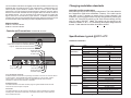
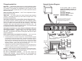
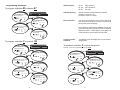
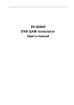
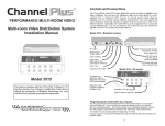
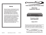
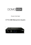
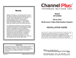
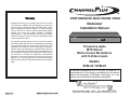
PERFORMANCE MULTI-ROOM VIDEO
Warranty
Multiplex Technology, Inc. warrants this product to be free
from defects in materials and workmanship for a period of
one year from the date of purchase or MTI will repair, or at its
option, replace the defective product. To obtain warranty
service, call MTI for a return material authorization (RMA)
number and return the product prepaid to Multiplex
Technology, Inc., 3001 Enterprise Street, Brea, CA 92821,
Attention: Customer Service. Please put the RMA number
on the outside of the carton.
Any implied warranty arising from the sale of the product
including implied warranties of merchantability and fitness
for purpose are limited to the warranty stated above. MTI
shall not be responsible for losses or damages or expenses,
whether direct, consequential or incidental arising from the
use of or the inability to use this product. Some states do not
allow limitations on how long the implied warranty lasts or
the exclusion or limitation or incidental or consequential
damages, so the above limitations and exclusions may not
apply to you. This warranty gives you specific legal rights,
and you may have other rights which may vary from state to
state.
Modulator
Installation Manual
SVM-24
A
B
C
D
select program
IR
Frequency-Agile
MTS Stereo
Multi-channel Modulators
with S-Video Inputs
Models
SVM-24 / SVM-22
This device complies with the FCC's Part 15 Rules for TV
interface devices. Any change or modification to this device
without the permission of Multiplex Technology, Inc. may
void the user's authority to operate this equipment.
3001 Enterprise Street,
600-224 Rev. B
Multiplex Technology, Inc., Brea, CA 92821
Brea,
CA
92821-6213,
U.S.A.
714-996-4100 * 800-999-5225 * FAX 714-996-4900 * www.channelplus.com
The ChannelPlus SVM Series are digitally-tuned video modulators that convert any
baseband video and audio signal to a user-selected UHF, or Ultraband CATV. An
internal quartz crystal reference oscillator and PLL circuitry ensure drift-free
performance. The user selects the output frequency (channel) using the "select"
button to choose which modulator and the "program" button to enter the number of
the desired channel. Any TV connected to the output via coax can receive the
signals, when the TV is tuned to the proper channel. In addition, the SVM series
encodes each channel using the MTS stereo standard. Stereo sound and surround
sound information will be received by any MTS compatible television receiver.
Models available:
SVM-24 4 channel modulator
SVM-22 2 channel modulator
Changing modulation standards
Cable HRC and IRC considerations
Most cable services use IRC frequency assignments. This is the default for
the ChannelPlus SVM series modulators. However, if the cable service
uses HRC or the TV appears to search for the "house channels," the
modulator can be reprogrammed to use HRC assignments by entering the
number “ 98”. Set to IRC by entering a “99”. Both of these settings are only
used for setting HRC/IRC. Note: This setting can be entered on any
modulator channel, A, B, C, or D, and affects all channel assignments for
that unit. Cable channels must either be all IRC or all HRC.
Controls and Connections - Model SVM-24 shown
SVM-24
Front
A
B
C
D
select program
Specifications: typical @ 25OC ± 5OC
IR
SVM Series modulators
LEDs show which modulator is selected
Select button chooses the modulator (A/B/C/D)
Program button enters the channel number
LED shows IR data transmission
Inputs
Video
performance
Right audio output
Left audio output
S-video output
VIDEO
RF Output
Power input
AUDIO L
AUDIO R
CH A
CH A
CH B
CH B
POWER
15VDC
900mA
CH C
CH D
OUTPUT
CH D
Back
CH C
RF output
VIDEO
AUDIO L
AUDIO R
VIDEO
AUDIO L
AUDIO R
VIDEO
AUDIO L
AUDIO R
S-video input
Left audio input
Right audio input
IR emitter outputs
AUTO TERMINATE FEATURE
All SVM modulators have built in loop through connectors so the user can connect video to
a second device. SVM modulators terminate the inputs into a 75 ohm load. When a
second cable is connected to the output, the SVM automatically disconnects this
termination to allow the second device to terminate.
BASEBAND VIDEO
The SVM modulators come with converter plugs for regular baseband video sources.
These can be used on inputs or outputs.
MOUNTING
The SVM modulators can be mounted in standard 19” racks by attaching the included
mounting ears. Remove the rubber feet on the bottom of the unit to ensure clearance
when inserted into a rack.
2
Power supply
Physical
MTS audio
performance
s-video
audio
differential gain
differential phase
signal/noise
standard
channel ranges
output level
IM distortion
alternate channel
model number
output current
output voltage
input power
power consumption
height
width
depth
weight
frequency range
signal/noise
separation
surround sound
noise reduction
7
1 Vp-p @ 75
1 V rms @ 47k
4%
<4º
55 dB
UHF
14-64
CATV
65-125
(excluding 95-99)
+25 dBmV (85dBuV)
-60 dBC
-45dBC @ 12MHz
SVM-22
900mA
SVM-24
900mA
15 VDC
105-125 VAC
9 watts
11 watts
4.4 cm (1.75 in)
43.2 cm (17 in)
16.5 cm (6.5 in)
1.19 kg (2 lbs 10 oz)
20Hz - 12kHz
65 dB
25 dB @ 1000Hz
Compatible with
Dolby full logic surround sound
Certified dbx
Sample System Diagram
No picture … Verify that the video source is on and is producing a video
signal. Check that the TV and the modulator are tuned to the same channel.
For example, if the modulator is broadcasting on UHF channel 16, make
sure the TV is on UHF 16 rather than CATV 16. UHF 16 and CATV 16 are at
different frequencies.
Local monitor
CCTV Camera
at front door
LEDs blink ... You need to have one unused channel space between
channels. The display will blink if you have made an ‘illegal’ choice. See
the section on programming.
Use converter plug for baseband sources without
s-video outputs like cameras. For applications
using the converter on the input, use another on
the output to loop to a baseband monitor.
Herringbone interference on ChannelPlus channel (diagonal lines) ...
You may have chosen a channel number that is not completely vacant.
Distant UHF stations may be un-watchable, but will cause interference if
you try to create a new channel at the same frequency. Also, cable
companies often have extra signals where there should be none. Try
moving the ChannelPlus channel to another number. You may have to add
a low pass filter to remove cable company noise.
VIDEO
Audio volume seems low compared to broadcast … There may be little
you can do here, other than turn up the volume. Here is what is happening:
!
!
In broadcast television, the audio is compressed: The soft sounds are amplified
to be almost as loud as the loud sounds. The technical measure of this is
dynamic range, the ratio of loudest to softest sounds. The dynamic range of
video devices such as DVD and LV players is very great. Since most of a typical
movie consists of ‘soft’ sounds, the audio will seem quieter than normal
television channels. (This is also why commercials, which are the most
compressed, seem louder than the program they accompany.)
To appear to be at the same volume as broadcast channels, the audio level in a
modulator is carefully increased. In the modulator, too high of signal level can
overdrive the MTS circuits and audio performance will suffer.
No Stereo … When using the TV outputs to send audio to a home theater system,
be sure the TV is in the stereo mode for external speakers. Consult the TV manual,
this is often confusing and is different for different TV brands.
No color on ChannelPlus channels … You may have chosen the
incorrect cable standard. Not all televisions can accommodate the
1.25MHz frequency difference between the H and I cable standards. See
the section on programming.
6
AUDIO L
AUDIO R
CH A
CH B
CH C
CH D
POWER
15VDC
900mA
CH D
OUTPUT
Herringbone interference on many channels (disappears when you
remove the modulator) … The high output of the ChannelPlus modulator
can overdrive many RF amplifiers. Reduce the RF output using an
attenuator. (ChannelPlus coax panels are designed to take the full output
of these modulators.)
CH C
SVM-24
CH B
Weak ChannelPlus UHF channel … If the TV has a separate UHF input,
be sure that it is connected.
In this system, CATV or antenna
channels are available on all TVs. In
addition the following channels have
been added:
Channel 66 - DVD player
Channel 68 - Front door channel
Channel 70 - WebTV
Channel 72 - Satellite receiver
CH A
Things to watch for:
VIDEO
AUDIO L
AUDIO R
DVD
VIDEO
AUDIO L
AUDIO R
VIDEO
AUDIO L
AUDIO R
SAT
WebTV
Attach the IR emitter directly
over the IR sensor.
RG6 coax
preferred
DA-550
(Distributes to as
many as 8 TVs)
To more TVs
2100A
Any or all TVs may have
a model 2132 IR Target
TARGET
LED
EMITTER
CATV/Antenna
POWER
TO
TV
Control the DVD,
DSS or VCR from
any room.
3
Programming Examples:
Valid Channels:
14-64: UHF channels
65-125: CATV channels
95-99: not valid
Channel Spacing:
Skip at least one number between channels.
Channels 14 and 16: OK.
Channels 14 and 15: Illegal.
Error indication:
If an error has occurred or an incorrect channel is
entered, the LED will flash quickly for a second and
return to the previous settings.
To program modulator B to channel 67
SVM-24
Press select button until
B channel LED is on
select
A
B
C
A
C
B
select program
D
IR
program
D
Press program button
6 times
select
A
B
C
program
D
Wait for B channel LED to light
(ready for next number.)
select
A
B
C
If two adjacent channels are selected, the unit will
accept the entry but will blink the LEDs of channels
that are too close. If this happens, re-program one
of the channels to move it away from the other.
program
Press program button
7 more times
D
select
A
B
C
program
D
Channel number
readback:
To program modulator C to channel 120
SVM-24
Press select button until
C channel LED is on
select
A
B
C
A
B
C
D
select program
IR
A readback mode will display the current channel
assignments.
To readback modulator C channel assignment
(example: C has been programmed to channel 108)
program
D
SVM-24
Press program button
1 time
select
A
B
C
program
D
A
select
A
B
C
select
B
C
select
Press program button
2 more times
select
IR
B
C
A
program
D
select
Press program button
10 more times
(press 10 to enter a ‘zero’)
select
A
4
B
C
D
C
program
D
Led blinks 1 time and pauses
A
D
B
program
Wait for C channel LED to light
(ready for next number.)
C
select program
program
program
D
A
B
D
Hold program button down
for 5 seconds, then release.
select
A
C
D
Wait for C channel LED to light
(ready for next number.)
A
B
Press select button until
C channel LED is on
B
C
program
D
Led blinks 10 times, pauses
(“10” is read back as 0)
select
A
Led blinks 8 times
program
select
A
B
C
program
D
5
B
C
D
program