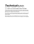
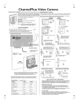
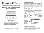
1
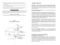
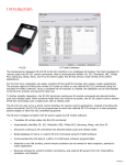
TM
PERFORMANCE MULTI-ROOM VIDEO
Warranty
Multiplex Technology, Inc. warrants this product to be free
from defects in materials and workmanship for a period of
one year from the date of purchase or MTI will repair, or at
its option, replace the defective product. To obtain
warranty service, call MTI for a return material
authorization (RMA) number and return the product
prepaid to Multiplex Technology, Inc., 3001 Enterprise
Street, Brea, CA 92821, Attention: Customer Service.
Please put the RMA number on the outside of the carton.
Modulator
Installation Manual
pwr
IR
program
TM
Any implied warranty arising from the sale of the product
including implied warranties of merchantability and fitness
for purpose are limited to the warranty stated above. MTI
shall not be responsible for losses or damages or
expenses, whether direct, consequential or incidental
arising from the use of or the inability to use this product.
Some states do not allow limitations on how long the
implied warranty lasts or the exclusion or limitation or
incidental or consequential damages, so the above
limitations and exclusions may not apply to you. This
warranty gives you specific legal rights, and you may have
other rights which may vary from state to state.
model 5515 digital modulator with ir output
pll frequency control
Frequency-Agile
Video Modulator
Model 5515
This device complies with the FCC's Part 15 Rules for TV
interface devices. Any change or modification to this
device without the permission of Multiplex Technology, Inc.
may void the user's authority to operate this equipment.
multiplex
®
technology, inc.
3001 Enterprise Street,
600-226 Rev B
Multiplex Technology, Inc., Brea, CA 92821
Printed in China
Brea,
CA
92821-6213,
U.S.A.
714-996-4100 * 800-999-5225 * FAX 714-996-4900 * www.channelplus.com
IMPORTANT SAFETY INSTRUCTIONS
Notes:
1) Read Instructions - All the safety and operating instructions should be read before the
product is operated.
2) Retain Instructions - The safety and operating instructions should be retained for future
reference.
3) Heed Warnings - All warnings on the product and in the operating instructions should be
adhered to.
4) Follow Instructions - All operating and use instructions should be followed.
5) Cleaning - Unplug this product from the wall outlet before cleaning. Do not use liquid
cleaners or aerosol cleaners. Use a damp cloth for cleaning.
6) Attachments - Do not use attachments not recommended by the product manufacturer as
they may cause hazards.
7) Water and Moisture - Do not use this product near water - for example, near a bath tub,
wash bowl, kitchen sink, or laundry tub; in a wet basement; or near a swimming pool; and
the like.
8) Accessories - Do not place this product on an unstable cart, stand, tripod, bracket, or
table. The product may fall, causing serious injury to a child or adult, and serious damage
to the product. Use only with a cart, stand, tripod, bracket, or table recommended by the
manufacturer, or sold with the product. Any mounting of the product should follow the
manufacturer's instructions, and should use a mounting accessory recommended by the
manufacturer.
9) A product and cart combination should be moved with care. Quick stops, excessive force,
and uneven surfaces may cause the product and cart combination to overturn.
10) Ventilation - Slots and openings in the cabinet are provided for ventilation and to ensure
reliable operation of the product and to protect it from overheating, and these openings
must not be blocked or covered. The openings should never be blocked by placing the
product on a bed, sofa, rug, or other similar surface. This product should not be placed
in a built-in installation such as a bookcase or rack unless proper ventilation is provided
or the manufacturer's instructions have been adhered to.
11) Power Sources - This product should be operated only from the type of power source
indicated on the marking label. If you are not sure of the type of power supply to your
home, consult your product dealer or local power company. For products intended to
operate from battery power, or other sources, refer to the operating instructions.
12) Grounding or Polarization - This product may be equipped with a polarized alternatingcurrent line plug (a plug having one blade wider than the other). This plug will fit into the
power outlet only one way. This is a safety feature. If you are unable to insert the plug
fully into the outlet, try reversing the plug. If the plug should still fail to fit, contact your
electrician to replace your obsolete outlet. Do not defeat the safety purpose of the
polarized plug.
13) Power-Cord Protection - Power-supply cords should be routed so that they are not
likely to be walked on or pinched by items placed upon or against them, paying
particular attention to cords at plugs, convenience receptacles, and the point where
they exit from the product.
2
11
O
O
Specifications: typical @ 25 C ± 5 C
5515 Modulator
Inputs
Video
performance
RF output
Power supply
Physical
1 Vp-p @ 75
1 V rms @ 47k
L & R inputs combined for monaural
video
audio
differential gain
differential phase
signal/noise
standard
channel ranges
4%
<4º
55 dB
UHF
14-64
CATV
65-125
(excluding 95-99)
+25 dBmV (90dBuV)
-60 dBC
-45dBC @ 12MHz
output level
IM distortion
alternate channel
model number
output current
output voltage
input voltage
power consumption
height
width
depth
weight
350-079
600mA
15 VDC
105-125 VAC
5 watts
2.5 cm (1.0 in)
11.7 cm (4.6 in)
8.1 cm (3.2 in)
9.6 oz (0.273kg)
DECLARATION OF CONFORMITY
THIS DEVICE COMPLIES WITH PART 15 OF THE FCC RULES. OPERATION IS
SUBJECT TO THE FOLLOWING TWO CONDITIONS: (1) THIS DEVICE MAY NOT CAUSE
HARMFUL INTERFERENCE, AND (2) THIS DEVICE MUST ACCEPT ANY INTERFERENCE
RECEIVED, INCLUDING INTERFERENCE THAT MAY CAUSE UNDESIRED OPERATION.
14) Protective Attachment Plug - The product is equipped with an attachment plug having
overload protection. This is a safety feature. See Instruction Manual for replacement
or resetting of protective device. If replacement of the plug is required, be sure the
service technician has used a replacement-plug specified by the manufacturer that
has the same overload protection as the original plug.
15) Outdoors Antenna Grounding - If an outside antenna or cable system is connected to
the product, be sure the antenna or cable system is grounded so as to provide some
protection against voltage surges and built-up static charges. Article 810 of the
National Electrical Code, ANSI/NFPA 70, provides information with regard to proper
grounding of the mast and supporting structure, grounding of the lead-in wire to an
antenna discharge unit, size of grounding conductors, location of antenna-discharge
unit, connection to grounding electrodes, and requirements for the grounding
electrode. See figure A.
16) Lightning - For added protection for this product during a lightning storm, or when it is
left unattended and unused for long periods of time, unplug it from the wall outlet and
disconnect the antenna or cable system. This will prevent damage to the product due
to lightning and power-line surges.
17) Power Lines -An outside antenna system should not be located in the vicinity of
overhead power lines or other electric light or power circuits, or where it can fall into
such power lines or circuits. When installing an outside antenna system, extreme care
should be taken to keep from touching such power lines or circuits as contact with
them might be fatal.
18) Overloading - Do not overload wall outlets, extension cords, or integral convenience
receptacles as this can result in a risk of fire or electric shock.
19) Object and Liquid Entry - Never push objects of any kind into this product through
openings as they may touch dangerous voltage points or short-out parts that could
result in a fire or electric shock. Never spill liquid of any kind on the product.
20) Servicing - Do not attempt to service this product yourself as opening or removing
covers may expose you to dangerous voltage or other hazards. Refer all servicing to
qualified service personnel.
For the Installer:
21) Damage Requiring Service - Unplug this product from the wall outlet and refer
servicing to qualified service personnel under the following conditions:
a) When the power-supply cord or plug is damaged,
b) If liquid has been spilled, or objects have fallen into the product,
c) If the product has been exposed to rain or water,
d) If the product does not operate normally by following the operating instructions.
Adjust only those controls that are covered by the operating instructions as an
improper adjustment of other controls may result in damage and will often
require extensive work by a qualified technician to restore the product to its
normal operation,
e) If the product has been dropped or damaged in any way, and
f ) When the product exhibits a distinct change in performance - this indicates a need for
service.
The system you design must comply with these regulations. As the installer, you are
responsible. The easiest way to be fully compliant is to use a ChannelPlus coax panel.
ChannelPlus panels have the necessary isolation from the modulator input ports to the
antenna input port and gain characteristic from the modulator input ports to the television
output ports. These features will make your modulator comply with the above requirements.
22) Replacement Parts - When re placement parts are required, be sure the service
technician has used replacement parts specified by the manufacturer or have the
same characteristics as the original part. Unauthorized substitutions may result in fire,
electric shock, or other hazards.
Installation requirements:
FCC classifies this product under part 15 of its rules as a “television interface device”.
Systems designed using television interface devices have the following legal requirements:
1) The modulated channel signal strength may not exceed 15.56dBmV at any television.
Federal Regulation 47CFR15.115(b)(1)(i).
2) If an antenna is used in the system, the modulated channel signal strength may not exceed
-51dBmV at the antenna input port. Federal Regulation 47CFR15.115(c)(4).
10
3
23) Safety Check - Upon completion of any service or repairs to this product, ask the
service technician to perform safety checks to determine that the product is in proper
operating condition.
24) Wall or Ceiling Mounting - The product should be mounted to a wall or ceiling only as
recommended by the manufacturer.
25) Heat - The product should be situated away from heat sources such as radiators, heat
registers, stoves, or other products (including amplifiers) that produce heat.
Note to CATV system installer
This reminder is provided to call the CATV system installer's attention to Section 820-40 of the
NEC which provides guidelines for proper grounding and, in particular, specifies that the cable
ground shall be connected to the grounding system of the building, as close to the point of
cable entry as practical.
POWER SUPPLY REPLACEMENT
Replace defective power supplies only with parts specified by the manufacturer.
Figure A
Example of antenna grounding as per
National Electrical Code, ANSI/NFPA 70
Things to watch for:
No picture … Verify that the video source is on and is producing a video
signal. Check that the TV and the modulator are tuned to the same channel.
For example, if the modulator is broadcasting on UHF channel 16, make
sure the TV is on UHF 16 rather than CATV 16. UHF 16 and CATV 16 are at
different frequencies.
Weak ChannelPlus UHF channel … If the TV has a separate UHF input,
be sure that it is connected.
Herringbone interference on ChannelPlus channel (diagonal lines) ...
You may have chosen a channel number that is not completely vacant.
Distant UHF stations may be un-watchable, but will cause interference if
you try to try to create a new channel at the same frequency. Also, cable
companies often have extra signals where there should be none. Try
moving the ChannelPlus channel to another number. You may have to add
a low pass filter to remove cable company noise.
Herringbone interference on many channels (disappears when you
remove the modulator) … The high output of the ChannelPlus modulator
can overdrive many RF amplifiers. Reduce the RF output using an
attenuator. (ChannelPlus coax panels are designed to take the full output of
these modulators.)
Audio volume is low … The left and right audio inputs are combined for
monaural. For proper audio level, both right and left inputs must be used. If
you have a mono source, connect it to both right and left inputs using an
RCA ‘Y’ connector.
No color on ChannelPlus channels … You may have chosen the
incorrect cable standard. Not all televisions can accommodate the
1.25MHz frequency difference between the H and I cable standards. See
the section on programming.
Changing modulation standards
Cable HRC and IRC considerations
Most cable services use IRC frequency assignments. This is the default for
the ChannelPlus 5500 series modulators. However, if the cable service
uses HRC or the TV appears to search for the "house channels," the
modulator can be reprogrammed to use HRC assignments by entering the
number “ 98”. Set to IRC by entering a “99”. Both of these settings are only
used for setting HRC/IRC.
4
9
Valid Channels:
14-64: UHF channels
65-125: CATV channels
95-99: not valid
Controls and Connections
Channel Spacing:
Skip at least one number between channels.
Channels 14 and 16: OK.
Channels 14 and 15: Illegal.
Error indication:
If an error has occurred or an incorrect channel is
entered, the LED will flash quickly for a second and
return to the previous settings.
Channel number
readback:
A readback mode will display the current channel
assignments.
The ChannelPlus 5500 Series are digitally-tuned video modulators that convert any
baseband video and audio signal to a user-selected UHF, or Ultraband CATV. An
internal quartz crystal reference oscillator and PLL circuitry ensure drift-free
performance. The user selects the output frequency (channel) using the "program"
button to enter the number of the desired channel. Any TV connected to the output
via coax can receive the signals, when the TV is tuned to the proper channel.
Model 5515 - Single channel agile modulator
pwr
IR
program
TM
pll frequency control
model 5515 digital modulator with ir output
To readback modulator channel assignment
(example: modulator is programmed to channel 108)
!
POWER LED
pwr
IR
program
TM
Hold program button
while applying power
pwr
IR
IR LED
Program button to enter
the channel number
program
LED blinks 1 time and pauses
pwr
OUTPUT
THE EXCLAMATION
POINT WITHIN THE
TRIANGLE IS A
WA R N I N G S I G N
ALERTING YOU OF
I M P O R TA N T
INSTRUCTIONS
A C C O M PA N Y I N G
T H E P R O D U C T.
pll frequency control
model 5515 digital modulator with ir output
program
IR
LED blinks 10 times, pauses
(“10” is read back as 0)
pwr
IR
program
!
LED blinks 8 times
pwr
IR
program
POWER
15VDC
600mA
OUTPUT
Remove jumper for Hi-Z
(See manual)
AUDIO
L
AUDIO
R
VIDEO
IR
REPEATER
RF output
Power supply
15VDC 600mA
Audio inputs: Right and left
are combined for monaural.
To hang with connectors on the side
To hang with connectors on the bottom or top
Mounting hole template
8
Video input
Video input termination jumper,
(on side of unit)(When connecting
video to a local monitor,
remove this jumper for hi-Z)
IR repeater
5
Sample System Diagram
Programming Examples:
In this system, CATV or antenna channels
are available on all TVs. In addition the
following channel has been added:
Channel 70 - Satellite receiver
To program modulator to channel 67
pwr
IR
program
TM
TM
Press program button
Attach the IR emitter
directly over the IR sensor.
SATELLITE
RECEIVER
6 times
pwr
IR
program
Wait for power LED
(ready for next number.)
Option:
To connect the video and audio to a local
monitor, use RCA type ‘Y’ adaptors and
remove the ’Termination’ jumper.
Video/audio
outputs
pll frequency control
pll frequency control
model 5515 digital modulator with ir output
model 5515 digital modulator with ir output
pwr
IR
program
Press program button
7 more times
pwr
!
POWER
15VDC
600mA
Use only shielded 75 ohm coax
OUTPUT
IR
program
Remove jumper for Hi-Z
(See manual)
AUDIO
R
AUDIO
L
VIDEO
IR
REPEATER
Model 2173 IR emitter repeats
what the IR target ‘sees’ in the
other room.
To program modulator to channel 120
pwr
IR
program
TM
Press program button
1 time
RG6 coax preferred
pwr
pll frequency control
model 5515 digital modulator with ir output
program
IR
Wait for power LED
(ready for next number.)
pwr
DA550HHR
or
DA550BID
To more TVs
2 more times
pwr
program
IR
Wait for power LED
(ready for next number.)
pwr
ET
RG
TA
IR
program
D
LER
TE
IT
EM
POWER OPTION:
CATV/Antenna
program
Press program button
Model 2132
IR Target
Any or all TVs may have
a model 2132 IR Target
The DA550 does not need to be powered
from its wall transformer when connected to
an Model 5515. It will be powered by the
modulator through the coax connection.
IR
ER
W
PO
Press program button
TO
TV
model 2100
IR interface
wall plate
6
Control the DVD,
DSS or VCR
from any room.
10 more times
pwr
IR
(press 10 times to
enter a ‘zero’)
program
Installer’s responsibility: To meet FCC part 15, use only a
coax panel with >76dB modulator input to antenna input
isolation. Also, the modulated signal must measure no more
than 15.56dBmV at any wall-plate. (Using ChannelPlus 3308
or 8200 panels will insure compliance.)
7