1
Channel
R
P E R F O R M A N C E M U LT I - R O O M V I D E O
Warranty
Multiplex Technology, Inc. warrants this product to be free
from defects in materials and workmanship for a period of
one year from the date of purchase or MTI will repair, or at
its option, replace the defective product. To obtain
warranty service, call MTI for a return material
authorization (RMA) number and return the product
prepaid to Multiplex Technology, Inc., 3001 Enterprise
Street, Brea, CA 92821, Attention: Customer Service.
Please put the RMA number on the outside of the carton.
Any implied warranty arising from the sale of the product
including implied warranties of merchantability and fitness
for purpose are limited to the warranty stated above. MTI
shall not be responsible for losses or damages or
expenses, whether direct, consequential or incidental
arising from the use of or the inability to use this product.
Some states do not allow limitations on how long the
implied warranty lasts or the exclusion or limitation or
incidental or consequential damages, so the above
limitations and exclusions may not apply to you. This
warranty gives you specific legal rights, and you may have
other rights which may vary from state to state.
Model
3015/3025
"All-In-One"
Multi-room Video Distribution System
INSTALLATION GUIDE
This device complies with the FCC's Part 15 Rules for TV
interface devices. Any change or modification to this
device without the permission of Multiplex Technology, Inc.
may void the user's authority to operate this equipment.
Patent Notice
Products protected by U.S. Patent No. 5,384,603 and others pending. Also
protected by .U.S.. Patent No. 4,509,211; Taiwan Patent No. 25,991;
United Kingdom Patent No. 2,140,182 with Hong Kong Registration 224;
Canada Patent No. 1,200,024; and other patents issued and pending, all
of these are licensed by Multiplex Technology, Inc. from Xantech
Corporation.
600-070 Rev C
Multiplex Technology, Inc., Brea, CA 92821
multiplex
®
technology, inc.
3001 Enterprise Street,
Brea,
CA
92821-6213,
U.S.A.
714-996-4100 * 800-999-5225 * FAX 714-996-4900 * www.channelplus.com
Introduction
humidity:
Thank you for selecting the ChannelPlus model 3015/3025
multi-room video distribution system. The 3015 is a singleinput modulator and the 3025 is a dual-input modulator. The
3015/3025 will provide crisp, clear pictures from one or two
video sources and the antenna or cable at four or five
viewing locations within the home.
As an added benefit, the ChannelPlus model 3025 can be
upgraded to provide infrared remote control of the two video
sources from any TV location.
Unpacking & Inspection
Caution: Read all instructions before installing.
Each ChannelPlus model 3015/3025 multi-room video
distribution system is carefully tested and inspected prior to
packaging. Its construction is robust. The 3015/3025 will
provide many years of great service, but please remember
that it is a very sophisticated piece of electronic equipment
and it should be handled with care. The 3015/3025 is not
designed to be used outside; it should be installed in a clean,
dry location.
2
Agency-Approvals
Performance
signal inputs:
signal outputs:
5% to 90% non-condensing
safety: UL, CSA for power module
EMI/EMC: FCC, part 15
Model 3015
two (2)
one (1) RF input
one (1) video input
Model 3025
three (3)
one (1) RF input
two (2) video inputs
four (4)
4 equal outputs
(with L+R audio)
five (5)
2 local, 3 distance
(with L+R audio)
Note: With the Model 3025, all outputs support IR operation
of remote devices when connected to a target assembly.
RF carriers:
frequency ranges:
RF power output:
video performance:
stability: ± 5 kHz
UHF
14 to 64
CATV 65 to 125 (excluding 95-99)
channel width: 6.0 MHz
audio offset: 4.5 MHz
sidebands: double
modulator:12.0 dBmV nominal (4000µV)
15.5 dBmV max (5670µV)
CATV/antenna: 6.0 dB straight gain from
input
differential gain: 4%, typical
O
differential phase error: 4 , typical
signal to noise ratio:
55 dB, typical
spurious output:
-57dBC min outside carrier ±12MHz
rejection:
50dB min isolation inside the carrier
±12MHz
input signal level:
video: 1.0 volt peak-to-peak into 75W
audio: 2.8 volt RMS max into 47kW
15
Common Questions
Can an amplifier be used on an output to drive signals
over longer cable paths?
No. The IR remote control feature will be defeated if an
external amplifier is used.
Can a splitter be used on one or more outputs in order
to add more TVs?
No. The model 3015/3025 Multi-room Video Distribution
System is a pre-engineered system providing optimum
signal levels to each TV for clear, crisp picture quality. Each
time a splitter is added, there is lowering of signal level
called insertion loss. Insertion losses upset system
performance. Additionally, the IR remote control feature will
be defeated.
Can I change from off-air antenna to cable without
problems?
Yes. Even though cable channels are set at different
frequencies than off-air channels, ChannelPlus model
3015/3025 will work with either. If you change from one
signal source to the other, you will have to retune the system
following the procedures of this manual.
Specifications
General
size:
height: 172 mm (6.8 in)
width: 140 mm (5.5 in)
depth: 51 mm (2.0 in)
weight:
1.19 kg (2 lbs 10 oz)
power:
transformer input : 115 VAC, 60 Hz
transformer output: 15 VDC, 300mA
consumption: 7 Watts, typical
Environment
temperature:
O
O
O
O
operating: 0 C to 50 C (32 F to 122 F)
O
O
O
O
storage: -30 C to 50 C (-22 F to 122 F)
14
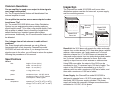
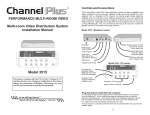
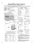
Inspection
The ChannelPlus model 3015/3025 multi-room video
distribution system consists of a base unit, a power supply,
and four mounting screws.
R
VIDEO DISTRIBUTION SYSTEM
Mounting
Screws
Model 3025
Base Unit
VIDEO MODULATOR / BROADBAND AMPLIFIER
Power
Supply
Model 3015
Base Unit
R
VIDEO DISTRIBUTION SYSTEM
DUAL VIDEO MODULATOR / BROADBAND AMPLIFIER / IR REPEATING SYSTEM
Base Unit: the 3015 base unit accepts the video and audio
outputs from a video device (VCR, laser disc player, satellite
receiver, video camera, etc.) and creates one "in-house"
television channel for it. The 3025 base unit accepts the
video and audio outputs from two video devices and creates
two "in-house" television channels for them. Both units
amplify an input from an off-air antenna or cable service.
Using RG6 coax cable, the output of the 3015 can be
connected to four TV receivers up to 150 feet of cable. The
output of the 3025 can be connected to up to five TV
receivers with two with a maximum of 35 feet of cable, and
three with a maximum of 150 feet of cable.
Power Supply: the ChannelPlus model 3015/3025 is
designed to operate from a 15 VDC power supply. Use only
the model 350-076 power supply provided. The power
supply will make the necessary voltage conversions when
connected to 115 VAC, 60 Hz power.
3
Other necessary items:
"House" video channels problems
Coaxial Cable: Sufficient coaxial cable type RG6 is needed
to connect each of the TVs in the home to the ChannelPlus
model 3015/3025 (RG59 can be used, but picture
performance may be compromised). Coaxial cable is
available two ways: in bulk or in pre-cut lengths. With bulk
cables, type "F" connectors must be attached to each end.
After reading all the instructions and reviewing the various
diagrams, the number of cables required and their proper
lengths can be determined.
Video Cables (a.k.a. VCR Cables): One or two sets of
these cables are required to connect the one or two video
devices (VCR, satellite receiver, laser disc player, video
camera, etc.) to the ChannelPlus model 3015/3025. Each
cable has an RCA-style connector on each end. A set
consists of three cables, a yellow for video, a red for right
audio, and a black or white for left audio. These sets
generally come in three or six foot lengths.
No picture: verify that the video source is on and is
producing a video signal. Check that the TV and the
3015/3025 are tuned to the same channel. For example, if
the 3015/3025 is broadcasting on UHF channel 16, make
sure the TV is on UHF 16 rather than CATV 16. UHF 16 and
CATV 16 are different channels. If the TV has a separate
UHF input, be sure that it is connected.
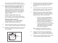
Poor picture quality: If the picture quality is poor due to
"hum bars" or "noise," then there is probably interference
coming from either a local off-air station or from noise on the
cable. Connect the cable service or antenna directly to a TV
and observe the picture. If it is anything other than pure
snow, the user must either change to a different channel or
add a filter. If a clear channel cannot be found, ChannelPlus
filters are available from the same source for ChannelPlus
products.
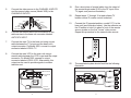
Infrared Remote Control Problems
Infrared remote control does not work: (Model 3025 only)
Check the red IR data light on the left side of the base unit.
Light on: If the light is on, one or more IR targets is
receiving electrical or optical noise. At the base
unit, begin to disconnect the outputs to the TVs
until the red LED goes off. Then, reposition the
probable target before connecting the coax to
the base unit.
Light off: With the aid of a helper, operate an IR remote
in front of each target while observing the IR
data light. A blinking data light indicates proper
operation. If all targets appear to be functioning
properly, reposition the emitters. Be sure the
emitters are in front of the IR sensor of the
video source.
4
13
23.
24.
Put a tape in the VCR. Press Play on the remote
control, then press Pause. If everything works OK at
the main TV location, go to step 24.
Now go to each distant TV equipped with a
ChannelPlus model 2133. Tune the TV to the VCR
channel. Aim the VCR's remote control at the
ChannelPlus model 2133 target, and press Play,
Pause, Rewind, etc. The VCR should respond as if
you were standing in front of it. If it does not, see The
Trouble Shooting Guide.
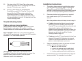
Installation Instructions
1.
The existing video equipment and television system
must be functioning correctly prior to installing the
ChannelPlus model 3015/3025. Ensure that all
antenna or cable signals are being received at least at
the main TV before proceeding with this installation.
2.
Determine whether local programming is supplied
from a cable service (CATV) or from an off-air
antenna.
Note: Keep written notes on this step to use in step 11.
Trouble Shooting Guide
a. If cable: determine the highest channel number
delivering a picture, excluding channels 95-99.
Tune the TV up one channel at a time from the last
channel with a picture until finding two nonadjacent channel numbers, each with no trace of a
picture or other interference - just snow. If no clear
channels can be found, consult the Trouble
Shooting Guide on page 12.
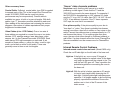
Cable or antenna channel problems
Grainy cable or antenna channels: This usually means
that the signal is weak and an RF amplifier is needed.
Please consider one of the amplifiers described on page 4.
No or weak UHF: Check rear of TV, if there are separate
VHF and UHF input terminals. Verify that the UHF terminal is
connected. If not, add a band separator.
b. If antenna: tune the TV one channel at a time from
channel 14 through 64. Write down the channel
number of each channel which has no trace of a
picture or other interference - just snow.
VHF/UHF band separator
VHF out
in
3.
Select an installation location for the base unit which
satisfies all of the following conditions:
a. close to the video sources
b. close to the antenna input or cable input
c. has a 110 VAC outlet within easy access
d. is clean and dry and likely to stay that way
4.
Fasten the base unit to the desired location using the
screws provided. The orientation is not critical.
UHF out
"Herringbones" : When most or all channels have
"herringbone" distortion, the signal may be too strong. If an
amplifier is being used remove it from the system.
Otherwise, use an in-line attenuator.
12
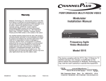
5
5.
Connect the video source to the CHANNEL A INPUTS
and the second video source (Model 3025) to the
CHANNEL B INPUTS.
Run a short piece of coaxial cable from the output of
the remote target model 2133 to the RF input of the
TV (again, see previous illustration).
20.
Repeat steps 17 through 19 at each distant TV
location where IR remote control is desired.
21.
Connect the IR repeater/emitters, model 2173, to the
base unit (see illustration below). Use the adhesive on
the IR emitter to hold it in place in front of the remote
sensor window on the first "house" video source.
Repeat this procedure for the second video source.
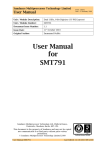
22.
The completed system should look like the following
illustration.
yellow
yellow
black or
white
video
19.
CH A CH B
red
red
black or
white
video
left audio
right audio
left audio
right audio
6.
Connect the coaxial cable from the antenna or the
cable service to the base unit connector labeled
ANT/CATV INPUT.
7.
Connect the main TV to the base unit using a coax
cable between the TV's input and the base unit's
output connector. On Model 3025, connect to output
connector labeled LOCAL TV.
8.
Connect the main VCR to the main unit using a
coaxial cable between the VCR's input and the output
connector. On Model 3025, connect to output
connector labeled LOCAL VCR. Alternatively, this
output can be used to provide signals to another
television set.
AUDIO
R
VIDEO
L
AUDIO
R
VIDEO
L
video source A
video source B
(VCR)
DSS
VCR
VIDEO
AUDIO
L
VIDEO
R
AUDIO
L
R
CATV or Antenna
input from
cable service
or antenna
6
11
can be used to enter HRC/IRC settings. It will not
affect the already programmed channel assignments.
16.
Optional IR Remote Control (Model 3025 only)
Either or both of the "house-channels" video
sources can be remotely controlled from any or all
distant TV locations. For example, the user in the
master bedroom can stop, pause, fast-forward the
VCR located in the family room. In order to do this,
additional IR equipment from your ChannelPlus
supplier is needed.
9.
Connect the output of the power supply to the base
unit and plug the power supply into a 110 VAC wall
outlet. The green LED power indicator should
illuminate.
10.
Turn on the main TV. The mode of the TV (CATV or
antenna) will determine the "in-house" channel that
will be used for viewing the two video sources.
11.
Select the "in-house" channel numbers referring to
notes made during step 2. These numbers will be
needed in step 13. Select a channel for the second
video source even if only one is being used.
IR Remote Target. Model number 2133.
One ChannelPlus IR remote target model 2133 for
each TV location where IR remote control is desired.
a. For CATV: select two unused channel
numbers, provided that they are at least
one unused channel apart from one
another, and at least one unused channel
above the last channel with picture.
b. For antenna: select two unused channel
numbers provided that they are at least one
unused channel away from one another
and at least one unused channel away
from a channel with picture.
IR Repeater/Emitter, model 2173
One or more model 2173 IR repeater/emitter is
required depending on the number of "housechannels" video sources to be controlled.
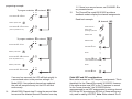
17.
Attach a remote target, model 2133, to the side or top
of the TV using the adhesive-backed feet. See below.
18.
Disconnect the cable from the RF input on the rear of
the TV, and reconnect it to the input to the model
2133. See below.
From Model 3025
10
Note: CHANNEL A and CHANNEL B must be
separated by at least one unused channel.
12.
Tune the TV to the channel number selected for
CHANNEL A. The TV or picture should be blank or
just plain snow. Turn on the channel A video source.
13.
Program the model 3015/3025 video channel A to the
"in-house" channel number selected in step 11.
7
programing example:
To program modulator
A
A
to channel
65
B
Press button A --- 6 times
11. If there is no second source, set CHANNEL B to
any unused channel.
15.
The ChannelPlus model 3015/3025 provides a
readback mode to display the channel assignments.
Read back example:
(A, channel 108)
Wait for power LED
A
Press button A --- 5 more times
(enter 10 presses for "0")
A
B
Press and hold
button while
powering up the unit
Wait for LED
To program modulator
A
A
to channel
108
B
Press button A --- 1 time
Release button
LED blinks 1 time
Wait for power LED
Pause
A
Press button A --- 10 more times
(enter 10 presses for "0")
B
LED blinks 10 times
("0" is read back as 10 blinks)
Wait for power LED
Pause
A
Press button A --- 8 more times
B
LED blinks 8 times
If an error has occurred, the LED will flash quickly for
a second and return to the previous settings. On
Model 3025, if two adjacent channels are selected,
the unit will accept the entry but the LED will blink
continuously.
14.
A
(Model 3025) Repeat step 13 using the second video
source and the selected channel B number from step
8
Cable HRC and IRC considerations
Most cable services use IRC frequency assignments. This is
the default for the ChannelPlus model 3015/3025. However,
if the cable service uses HRC or the TV appears to search
for the "house channels," the 3015/3025 can be
reprogrammed to use HRC assignments by entering channel
98. Set the IRC by entering a 99. Both of these settings are
only used for setting HRC/IRC. Note: Either channel A or B
9