1
Software User Guide
Cayman Operating System
Version 6.3
Cayman 3000 series by Netopia
January 2002
Downloaded from www.Manualslib.com manuals search engine
Disclaimers
Copyright © 2002 Netopia, Inc.
All rights reserved, Printed in the USA.
The information in this document is subject to change without notice. The statements, configurations, technical data, and recommendations in this document are believed to be accurate and reliable, but are presented without express or implied warranty. Users
must take full responsibility for the applications of any products specified in this document.
Portions of this software are subject to the Mozilla Public License Version 1.1. Portions created by Netscape are copyright 1994-2000
Netscape Communications Corporation. You may obtain a copy of the license at http://www.mozilla.org/MPL/. Software distributed
under the License is distributed on an “as is” basis, WITHOUT WARRANTY OF ANY KIND, either express or implied. See the License
for the specific language governing rights and limitations under the License.
Portions of this software copyright 1988, 1991 by Carnegie Mellon University. All rights reserved. Permission to use, copy, modify,
and distribute this software and its documentation for any purpose and without fee is hereby granted, provided that the above copyright notice and this permission notice appear in supporting documentation, and that the name of Carnegie Mellon University not
be used in advertising or publicity pertaining to distribution of the software without specific, written prior permission.
CARNEGIE MELLON UNIVERSITY DISCLAIMS ALL WARRANTIES WITH REGARD TO THIS SOFTWARE, INCLUDING ALL IMPLIED WARRANTIES OF MERCHANTABILITY AND FITNESS. IN NO EVENT SHALL CMU BE LIABLE FOR ANY SPECIAL, INDIRECT, OR CONSEQUENTIAL DAMAGES OR ANY DAMAGES WHATSOEVER RESULTING FROM LOSS OF USE, DATA, OR PROFITS, WHETHER IN AN
ACTION OF CONTRACT, NEGLIGENCE, OR OTHER TORTIOUS ACTION, ARISING OUT OF OR IN CONNECTION WITH THE USE OR
PERFORMANCE OF THIS SOFTWARE.
The information in this document is proprietary to Netopia, Inc.
Trademarks
Cayman Systems is a registered trademark of Cayman Systems, a division of Netopia, Inc. SWIFT-IP, SafetyNet, Zero Configuration,
SafeHarbour VPN IPsec Tunnel, and the Cayman Systems logo are trademarks of Netopia, Inc.
Ethernet is a registered trademark of Xerox Corporation. Microsoft and Windows are registered trademarks of Microsoft Corporation.
All other trademarks are the property of their respective owners. Mention of third-party products is for informational purposes only
and constitutes neither an endorsement nor a recommendation. Cayman assumes no responsibility with regard to the performance
or use of these products.
Statement of Conditions
In the interest of improving internal design, operational function, and /or reliability, Netopia, Inc. reserves the right to make changes
to the products described in this document without notice.
Netopia, Inc. does not assume any liability that may occur due to the use or application of the product(s) or network configurations described herein.
Netopia, Inc. Part Number: 6161103-PF-01
Downloaded from www.Manualslib.com manuals search engine
Table of Contents
Disclaimers ...........................................................................................................2
Table of Contents ................................................................................................3
Introduction .........................................................................................................7
Section 1
About Cayman Documentation ............................................................................................7
Intended Audience .................................................................................................................7
Documentation Conventions ................................................................................................8
General ..............................................................................................................................8
Internal Web Interface .....................................................................................................8
Command Line Interface ................................................................................................8
Icons ...................................................................................................................................9
Text ....................................................................................................................................9
Organization ..........................................................................................................................10
About Cayman-series Gateways ....................................................................11
Section 2
Basic Product Structure ........................................................................................................ 11
What’s New in Version 6.3 ...................................................................................................12
New Embedded Web Server ........................................................................................12
Maintenance Enhancements .........................................................................................12
Computer Names ...................................................................................................12
Updater ....................................................................................................................12
802.11b Wireless Update ........................................................................................12
NIST UTC Reference Signal ..................................................................................12
Capabilities Roadmap for COS 6.3 .....................................................................................13
Overview of Major Capabilities ....................................................................14
Section 3
General ...................................................................................................................................14
Feature Keys ...................................................................................................................14
Management ...................................................................................................................15
Embedded Web Server ..........................................................................................15
Diagnostics ..............................................................................................................15
Local Area Network ......................................................................................................16
DHCP (Dynamic Host Configuration Protocol) Server ....................................16
DHCP (Dynamic Host Configuration Protocol) Relay Agent .........................16
DNS Proxy ...............................................................................................................16
Wide Area Network ......................................................................................................17
DHCP (Dynamic Host Configuration Protocol) Client .....................................17
PPPoE (Point-to-Point Protocol over Ethernet) ..................................................17
Instant-On PPP ........................................................................................................17
Static IP Addresses .................................................................................................18
IPMaps .....................................................................................................................18
Security ............................................................................................................................19
Password Protection ...............................................................................................19
Network Address Translation (NAT) ..................................................................19
Cayman Advanced Features for NAT .................................................................20
Internal Servers .......................................................................................................20
Pinholes ....................................................................................................................21
Default Server .........................................................................................................21
3
Downloaded from www.Manualslib.com manuals search engine
Combination NAT Bypass Configuration ..........................................................22
Security Monitor .....................................................................................................22
Event Details ...........................................................................................................23
IP Source Address Spoofing ..........................................................................23
Source Routing .................................................................................................23
Subnet Broadcast Amplification ....................................................................23
Illegal Packet Size (Ping of Death) ................................................................23
Port Scan ...........................................................................................................24
Excessive Pings ................................................................................................24
Login Failures ..................................................................................................25
MAC Address Spoofing .................................................................................25
BreakWater Basic Firewall ....................................................................................26
BreakWater Settings ........................................................................................26
ClearSailing .....................................................................................................26
SilentRunning .................................................................................................26
LANdLocked ...................................................................................................26
VPN IPSec Pass Through .......................................................................................27
SafeHarbour VPN IPSec Tunnel ...........................................................................28
Web-based User Interface ...............................................................................29
Section 4
Access the User Interface .....................................................................................................29
Open the Web Connection ...........................................................................................29
Home page .............................................................................................................................30
Home page - Information .............................................................................................31
Toolbar ....................................................................................................................................32
Navigating the Web Interface ..............................................................................................32
Restart .....................................................................................................................................33
Help .........................................................................................................................................35
Configure ................................................................................................................................36
Quickstart ........................................................................................................................36
How to Use the Quickstart Page ..........................................................................36
Setup Your Gateway using a DHCP Connection ..............................................37
Change Procedure ..................................................................................................38
Setup Your Gateway using a PPP Connection ...................................................40
Setup Your Gateway using a Static IP Address .................................................41
Configuration Procedure ................................................................................41
LAN .................................................................................................................................43
WAN ................................................................................................................................44
Advanced ........................................................................................................................45
Configure Specific Pinholes ..................................................................................47
Planning for Your Pinholes ............................................................................47
Example: A LAN Requiring Three Pinholes ...............................................47
Pinhole Configuration Procedure .................................................................49
Configure the IPMaps Feature ..............................................................................52
FAQs for the IPMaps Feature ........................................................................52
IPMaps Block Diagram ...................................................................................54
Configure a Default Server ...................................................................................56
Typical Network Diagram .............................................................................57
NAT Combination Application .....................................................................57
Security ............................................................................................................................66
Create and Change Passwords .............................................................................67
Use a Cayman Firewall ..........................................................................................69
BreakWater Basic Firewall .............................................................................69
4
Downloaded from www.Manualslib.com manuals search engine
Configure a SafeHarbour VPN .............................................................................73
VPN IPSec Tunnel at the Gateway ..............................................................73
Parameter Description and Setup .................................................................74
IPSec Tunnel Parameter Setup Worksheet ..................................................76
SafeHarbour Tunnel Setup ............................................................................77
Using the Security Monitoring Log .....................................................................80
Install ...............................................................................................................................83
Install Software .......................................................................................................84
Updating Your Gateway to COS Version 6.3 ..............................................84
Install Keys ..............................................................................................................93
Use Cayman Software Feature Keys ....................................................................93
Troubleshoot ..........................................................................................................................97
Perform Troubleshooting on Gateways .......................................................97
System Status .......................................................................................................................101
Manage a Restricted Number of WAN Users .........................................................101
User Status .............................................................................................................101
Disconnect Current WAN Users ...............................................................................102
Exceeding the WAN User Limit ................................................................................103
Tour: Command Line Interface ....................................................................104
Appendix A
Overview ..............................................................................................................................104
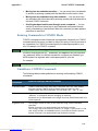
Starting and Ending a CLI Session ...................................................................................106
Connecting from telnet ...............................................................................................106
Connecting from the Maintenance Console Port ....................................................106
Logging In .....................................................................................................................106
Ending a CLI Session ...................................................................................................107
Saving Settings .............................................................................................................107
Using the CLI Help Facility ...............................................................................................107
About SHELL Commands .................................................................................................107
SHELL Prompt .............................................................................................................107
SHELL Command Shortcuts ......................................................................................107
Platform Convention ...................................................................................................108
SHELL Commands .............................................................................................................108
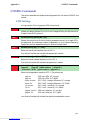
About CONFIG Commands .............................................................................................. 117
CONFIG Mode Prompt ...............................................................................................117
Navigating the CONFIG Hierarchy ..........................................................................117
Entering Commands in CONFIG Mode ...................................................................118
Guidelines: CONFIG Commands ..............................................................................118
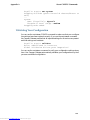
Displaying Current Gateway Settings ......................................................................119
Step Mode: A CLI Configuration Technique ...........................................................119
Validating Your Configuration ..................................................................................120
CONFIG Commands ..........................................................................................................121
ATM Settings ................................................................................................................121
Bridging Settings ..........................................................................................................122
DHCP Settings ..............................................................................................................123
DMT Settings ...............................................................................................................124
Domain Name System Settings .................................................................................124
Ethernet MAC Address Settings ...............................................................................124
IP Settings .....................................................................................................................125
Basic Settings ..........................................................................................................125
DSL Settings ............................................................................................................125
Ethernet Settings ......................................................................................................126
5
Downloaded from www.Manualslib.com manuals search engine
Default IP Gateway Settings ...................................................................................128
WAN-to-WAN Routing Settings ............................................................................129
IP-over-PPP Settings ...............................................................................................129
Static ARP Settings .................................................................................................131
Static Route Settings ...............................................................................................132
WAN Settings ..........................................................................................................133
IPMaps Settings ............................................................................................................134
Network Address Translation (NAT) Default Settings .........................................135
Network Address Translation (NAT) Pinhole Settings .........................................135
PPPoE Settings .............................................................................................................136
Configuring Basic PPP Settings ..............................................................................137
Configuring Port Authentication .............................................................................138
Configuring Peer Authentication .............................................................................140
Command Line Interface Preference Settings .........................................................141
Port Renumbering Settings ........................................................................................141
Security Settings ...........................................................................................................142
Firewall Settings (for BreakWater Firewall). ..........................................................142
SafeHarbour IPSec Settings ....................................................................................142
Internet Key Exchange (IKE) Settings ................................................................144
SNMP Settings ..............................................................................................................145
System Settings ............................................................................................................145
Traffic Shaping Settings ..............................................................................................147
Glossary ............................................................................................................148
Appendix B
Index ..................................................................................................................158
6
Downloaded from www.Manualslib.com manuals search engine
Section 1
About Cayman Documentation
Introduction
Section 1
About Cayman Documentation
Netopia, Inc. provides a suite of technical information for its Cayman-series
family of intelligent enterprise and consumer Gateways. It consists of:
•
Software User Guide
•
Hardware and Installation User Guide
•
Dedicated Quickstart booklets
•
Specific White Papers
The documents are available in electronic form as Portable Document Format (PDF) files. They are viewed (and printed) from Adobe Acrobat Reader,
Exchange, or any other application that supports PDF files.
They are downloadable from Cayman’s website: http://www.cayman.com/
Intended Audience
This guide is targeted to the technical staffs of organizations such as:
•
Incumbent Local Exchange Carriers (ILEC)
•
Competitive Local Exchange Carriers (CLEC)
•
Multiple System Operators (MS0)
•
Internet Service Providers (ISP)
These professional staffs include:
•
System administrators
•
Installation and configuration technicians
•
Customer support engineers
They are responsible for planning, deploying, and supporting the Customer Premise Equipment that are the key elements of small business or
residential Local Area Networks.
Business and residential subscribers are encouraged to use this guide also.
7
Downloaded from www.Manualslib.com manuals search engine
Section 1
Documentation Conventions
Documentation Conventions
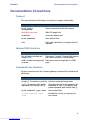
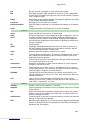
General
This manual uses the following conventions to present information:
Convention (Typeface)
Description
bold italic
monospaced
Menu commands and button names
bold italic sans serif
Web GUI page links
terminal
Computer display text
bold terminal
User-entered text
Italic
Italic type indicates the complete titles of
manuals.
Internal Web Interface
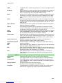
Convention (Graphics)
Description
dot-dot-dash rounded rectangle or line
Denotes an “excerpt” from a Web page or
the visual truncation of a Web page
solid rounded rectangle with Denotes an area of emphasis on a Web
an arrow
page
Command Line Interface
Syntax conventions for the Cayman gateway command line interface are
as follows:
Convention
Description
straight ([ ]) brackets in cmd line Optional command arguments
curly ({ }) brackets, with values
separated with vertical bars (|).
Alternative values for an argument are
presented in curly ({ }) brackets, with
values separated with vertical bars (|).
bold terminal type face
User-entered text
italic terminal type
face
Variables for which you supply your
own values
8
Downloaded from www.Manualslib.com manuals search engine
Section 1
Documentation Conventions
BOTH
Pointing to a CLI command, refers to
both DSL and Ethernet WAN interfaces
for Cayman Gateways
DSL
Pointing to a CLI command, refers only
to DSL WAN interface (used with 3220H family)
ENET
Pointing to a CLI command, refers only
to ENET WAN interface (used with 2E-H
family)
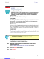
Icons
Icons used in the guide are:
Icon
Description
NOTE Icon:
Requests that you pay particular attention to a specified
procedure or piece of information in the text. The NOTE
message has a regular type style.
CAUTION Icon:
Suggest you review the referenced details and heed the
instructions offered. The CAUTION message has a bold
type style.
WARNING Icon:
Demands that you observe the actions given in the text.
The WARNING message has a bold italic type style.
COMPASS Icon:
Points the user to additional information concerning the topic
under discussion. The COMPASS message has a regular type
style. It is used also to denote a Roadmap table.
Text
The words “Cayman Gateway” and “Gateway” refer to a standard unit
from the Netopia Cayman 3000-Series product families.
9
Downloaded from www.Manualslib.com manuals search engine
Section 1
Organization
The expressions “Release 6.3.0” and “R 6.3.0” refer to the most recent
generally available Cayman Operating System: COS 6.3.0R0.
Organization
This guide consists of six sections, three appendixes including a glossary,
and an index. It is organized as follows:
•
Section 1, “Introduction” — Describes the Cayman document suite,
the purpose of, the audience for, and structure of this guide. It presents
a table of conventions.
•
Section 2, “About Cayman Gateways” — Presents a product description and overview of the extensive features of your Cayman gateway
including a listing of new capabilities that are included with Cayman
Operating System COS 6.3. A “Roadmap” of features and How To topics is shown.
•
Section 3, “Overview of Major Capabilities,” — Itemizes Local Area
Network, Wide Area Network, Security, Management, and Software
Feature Keys features and functionalities.
•
Section 4, “Web-based User Interface,” — Organized in the same
way as the web UI is organized. As you go through each section, functions and procedures are discussed in detail.
•
Appendix A, “Tour of the Command Line Interface,” — Describes all
the current text-based commands for both the SHELL and CONFIG
modes. A summary table and individual command examples for each
mode is provided.
•
Appendix B, “Glossary”
•
Index
10
Downloaded from www.Manualslib.com manuals search engine
Section 2
Basic Product Structure
About Cayman-series Gateways
Section 2
Basic Product Structure
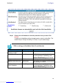
Units from the Netopia Cayman-series Gateway family are supplied in
many configurations. This presents end-users with many alternatives for
Wide Area Network (WAN) interfaces and Local Area Network (LAN) interfaces. This is the current product roster that supports COS 6.3:
Cayman
Model No.
3220-H
WAN Interface
Full-Rate Discrete MultiTone (DMT) Asynchronous
Digital Subscriber Line
(ADSL)
LAN Wired
Ethernet Hub
LAN Wired
Options
LAN
Wireless
Option
Four ports
10 BaseT
3220-H-W11 ADSL
Four ports
10 BaseT
802.11b
Protocol
3220-H-WRF ADSL
Four ports
10 BaseT
HomeRF
Protocol
2E
Ethernet
One port
10 BaseT
2E-H
Ethernet
Eight ports
10 BaseT
2E-H-W11
Ethernet
Eight ports
10 BaseT
802.11b
Protocol
2E-H-WRF
Ethernet
Eight ports
10 BaseT
HomeRF
Protocol
3445
ADSL
Four ports 10/
100 Ethernet
3543
ADSL
Four ports 10/
100 Ethernet
3485
Ethernet
Four ports 10/
100 Ethernet
3583
Ethernet
Four ports 10/
100 Ethernet
HPNA
PCMCIA
802.11b
Protocol
HPNA
PCMCIA
802.11b
Protocol
11
Downloaded from www.Manualslib.com manuals search engine
Section 2
What’s New in Version 6.3
What’s New in Version 6.3
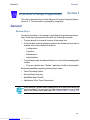
The new features for COS 6.3 are:
New Embedded Web Server
Not only is the look and feel different, but the database and the web server
engine are new and more flexible.
The design of the new web server is geared to make navigation easier, providing the most commonly used items first. Context-sensitive help is provided.
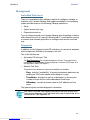
Maintenance Enhancements
The maintenance enhancements are:
Computer Names
In addition to the IP address, the computer name is now listed in the DHCP
lease table and the WAN users table. This allows users to more easily identify the computers in these tables. The computer name is only known if
using DHCP to get its IP address.
Updater
This application, Updater Version 1.1, prepares the Gateway for installation
of COS 6.3
Updater V 1.1 is required for users running COS 5.6.2 or lower.
For complete details see page 84 of this document.
802.11b Wireless Update
Improved software to support 802.11b wireless base stations response to
client requests made after an extended period of LAN inactivity.
NIST UTC Reference Signal
Cayman Gateways acquire the Universal Coordinated Time reference signal
from the National Institute of Standards and Technology. This provides
date and time information for log entries.
12
Downloaded from www.Manualslib.com manuals search engine
Section 2
Capabilities Roadmap for COS 6.3
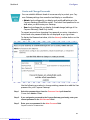
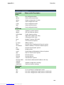
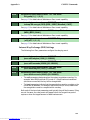
Capabilities Roadmap for COS 6.3
Cayman Gateways support a wide array of features and functionality. This
roadmap points you to overview discussions and How To procedures.
Capabilities Roadmap:
Cayman Gateways with COS 6.3
Feature
New for COS
6.3
Outline
Page
Details
Software Feature Keys
Yes
14
93
Embedded Web Server
Changed
15
29
Diagnostics
15
99
DHCP Server
16
59
DHCP Relay-agent
16
59
DNS Proxy
16
124
DHCP Client
17
123
PPPoE
17
136
18
41
18
52
21
46
General
Management
LAN
WAN
Multiple PPPoE Sessions
Yes
Static IP Address
IPMaps (Multiple Static IP Addresses)
Yes
Pinholes
User Limits
103
Yes
Security
Password Protection
19
Network Address Translation (NAT)
19
Instant-On PPP
17
138
22
80
27
73
Security Monitoring Log
Yes
VPN IPSec Pass Through
66
SafeHarbour VPN IPSec Tunnel
Yes
28
73
BreakWater Basic Firewall
Yes
26
69
13
Downloaded from www.Manualslib.com manuals search engine
Section 3
General
Overview of Major Capabilities
Section 3
This section describes the principal features of Cayman Operating System
version 6.3. The information is grouped by usage area.
General
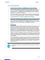
Feature Keys
Certain functionality in this release is controlled through software feature
keys. These keys are proprietary files with the following properties:
•
They are specific to the serial number of the target unit.
•
Once installed, and the Gateway restarted, the desired enhancement is
enabled, which then allows full access to:
•
–
Configuration
–
Operation
–
Maintenance
–
Administration
They will not enable the desired feature on a unit with the wrong serial
number.
–
They are rejected upon “Restart”, not when the file is downloaded.
Enhanced capabilities requiring a feature key include:
•
Tiered Operating System
•
Security Monitoring Log
•
BreakWater Basic Firewall
•
SafeHarbour IPSec Tunnel Termination
Many Netopia Cayman-series Gateways ship with particular feature key
sets pre-enabled. You can check the feature keys enabled on your Gateway in the System Status web page. See “System Status” on page 101.
14
Downloaded from www.Manualslib.com manuals search engine
Section 3
General
Management
Embedded Web Server
There is no specialized client software required to configure, manage, or
maintain your Cayman Gateway. Web pages embedded in the operating
system provide access to the following Gateway operations:
•
Setup
•
System and security logs
•
Diagnostics functions
Once you have removed your Cayman Gateway from its packing container
and powered the unit up, use any LAN attached PC or workstation running
a common web browser application to configure and monitor the Gateway.
Diagnostics
In addition to the Gateway’s visual LED indicators, you access an extensive
suite of diagnostic facilities by browsing to the unit.
Two of the facilities are:
•
Automated “Multi-Layer” Test
The Run Diagnostics link initiates a sequence of tests. They examine the
functionality of the Gateway, from the physical connections (OSI Layer 1) to
the application traffic (OSI Layer 7).
•
Network Test Tools
Three test tools to determine network reachability are available:
–
Ping - tests the “reachability” of a particular network destination by
sending an ICMP echo request and waiting for a reply.
–
TraceRoute - displays the path to a destination by showing the
number of hops and the router addresses of these hops.
–
NSLookup - converts a domain name to its IP address and vice
versa.
The system log also provides diagnostic information.
Your Service Provider may request information that you acquire from
these various diagnostic tools. Individual tests may be performed at the
command line. (See Appendix A).
15
Downloaded from www.Manualslib.com manuals search engine
Section 3
General
Local Area Network
DHCP (Dynamic Host Configuration Protocol) Server
DHCP Server functionality enables the Gateway to assign your LAN computer(s) a “private” IP address and other parameters that allow network
communication. The default DHCP Server configuration of the Gateway
supports up to 253 LAN IP addresses.
This feature simplifies network administration because the Gateway maintains a list of IP address assignments. Additional computers can be added
to your LAN without the hassle of configuring an IP address.
DHCP (Dynamic Host Configuration Protocol) Relay Agent
DHCP Relay functionality enables the Gateway to forward a DHCP client
request to a specified DHCP Server. This assigned DHCP Server will reply to
the request with an IP address and other network parameters.
DNS Proxy
Domain Name System (DNS) provides end users with the ability to look for
devices or web sites through the use of names, rather than IP addresses.
For websurfers, this technology allows a user to enter the URL (Universal
Resource Locator) text string to access a desired website. Each text string
identifier has an associated IP address, a series of numbers in the format of
xxx.xxx.xxx.xxx (e.g. 147.240.101.006). It is DNS servers that are responsible for this text-to-IP Address translation. DNS Servers, in most cases, are
located at Internet Service Provider facilities. They translate domain names
into the desired IP address for locating an Internet website by answering
DNS requests.
The Cayman DNS Proxy feature allows the LAN-side IP address of the Gateway to be used for proxying DNS requests from hosts on the LAN to the
DNS Servers configured in the gateway. This is accomplished by having the
Gateway's LAN address handed out as the “DNS Server” to the DHCP clients on the LAN.
The Cayman DNS Proxy only proxies UDP DNS queries, not TCP DNS
queries.
16
Downloaded from www.Manualslib.com manuals search engine
Section 3
General
Wide Area Network
DHCP (Dynamic Host Configuration Protocol) Client
DHCP Client functionality enables the Gateway to request an IP address
from your Service Provider. DHCP servers on your Service Provider’s network reply to DHCP Client requests and assign the network parameters.
PPPoE (Point-to-Point Protocol over Ethernet)
The PPPoE specification, incorporating the PPP and Ethernet standards,
allows your computer(s) to connect to your Service Provider’s network
through your Ethernet WAN connection. The Netopia Cayman-series Gateway supports PPPoE, eliminating the need to install PPPoE client software
on any LAN computers.
Service Providers may require the use of PPP authentication protocols such
as Challenge Handshake Authentication Protocol (CHAP) or Password
Authentication Protocol (PAP). CHAP and PAP use a username and password pair to authenticate users with a PPP server.
A CHAP authentication process works as follows:
1. The password is used to scramble a challenge string.
2. The password is a shared secret, known by both peers.
3. The unit sends the scrambled challenge back to the peer.
PAP, a less robust method of authentication, sends a username and password to a PPP server to be authenticated. PAP’s username and password
pair are not encrypted, and therefore, sent “unscrambled”.
Instant-On PPP
You can configure your Gateway for one of two types of Internet connections:
•
Always On
•
Instant On
These selections provide either an uninterrupted Internet connection or an
as-needed connection.
While an Always On connection is convenient, it does leave your network
permanently connected to the Internet, and therefore potentially vulnerable to attacks.
Cayman's Instant On technology furnishes almost all the benefits of an
Always-On connection while providing two additional security benefits:
•
Your network cannot be attacked when it is not connected.
17
Downloaded from www.Manualslib.com manuals search engine
Section 3
General
•
Your network may change address with each connection making it
more difficult to attack.
When you configure Instant On access, you can also configure an idle
time-out value. Your Gateway monitors traffic over the Internet link and
when there has been no traffic for the configured number of seconds, it
disconnects the link.
When new traffic that is destined for the Internet arrives at the Gateway,
the Gateway will instantly re-establish the link.
Your service provider may be using a system that assigns the Internet
address of your Gateway out of a pool of many possible Internet addresses.
The address assigned varies with each connection attempt, which makes
your network a moving target for any attacker.
Static IP Addresses
If your Service Provider requires the Cayman Gateway to use Static IP
addressing, you must configure your Gateway for it. Dynamically assigned
addresses allow a service provider’s customer to install their Gateway without WAN configuration. Static addresses never time out; dynamic
addresses time out and will be reassigned.
A static IP address is preferred for setting up and maintaining pinholes
through the Cayman Gateway’s NAT security facility.
Your Service Provider may not offer a static IP address option.
IPMaps
IPMaps supports one-to-one Network Address Translation (NAT) for IP
addresses assigned to servers, hosts, or specific computers on the LAN side
of the Cayman Gateway.
With IPMaps, a Service Provider-assigned static IP address is mapped to a
specific internal device. This allows a LAN-located device to appear public
without compromising other locally attached devices. The external IP
addresses must be on the same subnet.
IPMaps is used for applications such as Web, email, and FTP servers.
See How To: Configure for IPMaps on page 52 for more information.
18
Downloaded from www.Manualslib.com manuals search engine
Section 3
General
Security
Password Protection
Access to your Cayman device is controlled through two access control
accounts, Admin or User.
•
The Admin, or administrative user, performs all configuration, management or maintenance operations on the Gateway.
•
The User account provides monitor capability only.
A user may NOT change the configuration, perform upgrades or invoke
maintenance functions.
For the security of your connection, an Admin password must be set on the
Cayman unit.
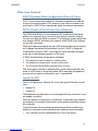
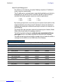
Network Address Translation (NAT)
The Cayman Gateway Network Address Translation (NAT) security feature
lets you conceal the topology of a hard-wired Ethernet or wireless network
connected to its LAN interface from routers on networks connected to its
WAN interface. In other words, the end computer stations on your LAN are
invisible from the Internet.
Only a single WAN IP address is required to provide this security support
for your entire LAN.
LAN sites that communicate through an Internet Service Provider typically
enable NAT, since they usually purchase only one IP address from the ISP.
•
When NAT is ON, the Cayman Gateway “proxies” for the end computer stations on your network by pretending to be the originating host
for network communications from non-originating networks. The WAN
interface address is the only IP address exposed.
The Cayman Gateway tracks which local hosts are communicating with
which remote hosts. It routes packets received from remote networks to
the correct computer on the LAN (Ethernet A) interface.
•
When NAT is OFF, a Cayman Gateway acts as a traditional TCP/IP
router, all LAN computers/devices are exposed to the Internet.
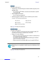
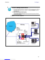
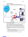
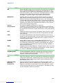
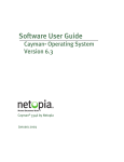
A diagram of a typical NAT-enabled LAN is shown below:
19
Downloaded from www.Manualslib.com manuals search engine
Section 3
General
WAN
Internet
Dual Ethernet Gateway
LAN
Ethernet
Interface
Ethernet
Interface
NAT
Cable
Modem
NAT-protected
LAN stations
Embedded Admin Services:
HTTP-Web Server and Telnet Server Port
A similar configuration applies to a DSL WAN interface (3220 family).
1. The default setting for NAT is ON.
2. Cayman uses Port Address Translation (PAT) to implement the NAT
facility.
3. NAT Pinhole traffic (discussed below) is always initiated from the
WAN side.
Cayman Advanced Features for NAT
Using the NAT facility provides effective LAN security. However, there are
user applications that require methods to selectively by-pass this security
function for certain types of Internet traffic.
Cayman Gateways provide special pinhole configuration rules that enable
users to establish NAT-protected LAN layouts that still provide flexible bypass capabilities.
Some of these rules require coordination with the unit’s embedded administration services: the internal Web (HTTP) Port (TCP 80) and the internal
Telnet Server Port (TCP 23).
Internal Servers
Related to the pinhole configuration rules is an internal port forwarding
facility that enables you to:
•
Direct traffic to specific hosts/computers on the LAN side of the Gateway.
•
Eliminate conflicts with embedded administrative ports 80 and 23.
20
Downloaded from www.Manualslib.com manuals search engine
Section 3
General
Pinholes
This feature allows you to:
•
Transparently route selected types of network traffic using the port forwarding facility.
–
•
Setup multiple pinhole paths.
–
•
FTP requests or HTTP (Web) connections are directed to a specific
host on your LAN.
Up to 32 paths are supported
Identify the type(s) of traffic you want to redirect by port number.
Common TCP/IP protocols and ports are:
FTP (TCP 21)
telnet (TCP 23)
SMTP (TCP 25)
HTTP (TCP 80)
SNMP (TCP 161, UDP 161)
See page 47 for How To instructions.
Default Server
This feature allows you to:
•
Direct your Gateway to forward all externally initiated IP traffic (TCP
and UDP protocols only) to a default host on the LAN.
•
Enable it for certain situations:
–
Where you cannot anticipate what port number or packet protocol
an in-bound application might use.
For example, some network games select arbitrary port numbers
when a connection is opened.
–
When you want all unsolicited traffic to go to a specific LAN host.
Default Server is not available for traffic inbound via a SafeHarbour IPsec
tunnel.
See page 56 for How To instructions.
21
Downloaded from www.Manualslib.com manuals search engine
Section 3
General
Combination NAT Bypass Configuration
Specific pinholes and Default Server settings, each directed to different
LAN devices, can be used together.
Creating a pinhole or enabling a Default Server allows inbound access
to the specified LAN station. Contact your Network Administrator for
LAN security questions.
Security Monitor
The Security Monitor detects security related events including common
types of malicious attacks and writes them to a dedicated security log file.
You view this log file from either:
•
Cayman Web interface
•
Text-based command line interface using a telnet or serial port facility
The log provides information useful in identifying a specific type of attack
and tracing its origin. The log maintains 100 entries, and requires a manual
reset once full. This preserves for troubleshooting purposes the acquired
information about specific attacks, their frequency and tracing information.
See page 80 for more information about the Security Monitoring Log.
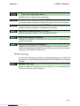
COS 6.3 Security Monitor software reports the following eight event types:
•
IP Source Address Spoofing
•
Source Routing
•
Subnet Broadcast Amplification
•
Illegal Packet Size (Ping of Death)
•
Port Scan (TCP/UDP)
•
Excessive Pings
•
Admin Login Failure
•
MAC Address Spoofing
22
Downloaded from www.Manualslib.com manuals search engine
Section 3
General
Event Details
Details on the eight specific event types and the information logged are:
IP Source Address Spoofing
The Gateway checks all incoming packets to see if the IP address attached
is valid for the interface the packet is received through. If the address of the
packet is not valid for the interface the packet is discarded.
Logged information includes:
IP source address
Number of attempts
IP interface
IP destination address
Time at last attempt
Source Routing
IP source routing information packets will be received and accepted by the
Cayman Gateway. Logging of this activity is provided in the event the
source route information has been forged, but appears as valid data.
Logged information includes:
IP source address
Number of attempts
IP interface
IP destination address
Time at last attempt
Subnet Broadcast Amplification
Distributed DoS (Denial of Service) attacks often use a technique known as
broadcast amplification, in which the attacker sends packets to a router’s
subnet broadcast address. This causes the router to broadcast the packet to
each host on the subnet. These, in turn, become broadcast sources,
thereby involving many new hosts in the attack. The Cayman unit detects
and discards any packets that would otherwise be transmitted to a subnet
broadcast address. The Security Monitoring logs the event.
Logged information includes:
IP source address
Number of attempts
IP broadcast address
IP destination address
Time at last attempt
Illegal Packet Size (Ping of Death)
The maximum size of an IP packet is 64K bytes, but large packets must
usually be fragmented into smaller pieces to travel across a network. Each
fragment contains some information that allows the recipient to reassemble all of the fragments back into the original packet. However, the frag-
23
Downloaded from www.Manualslib.com manuals search engine
Section 3
General
mentation information can also be exploited to create an illegally sized
packet. Unwary hosts will often crash when the illegal fragment corrupts
data outside of the “normal” packet bounds. The Cayman unit will detect
and discard illegal packet fragments, and the Security Monitoring software
logs the event.
Logged information includes:
IP source address
Number of attempts
Illegal packer size
IP destination address
Time at last attempt
Port Scan
Port scanning is the technique of probing to determine the list of TCP or
UDP ports on which a host, or in our case, a Gateway is providing services.
For example, the HTTP service is usually available on TCP port 80. Once
hackers have your port list, they can refine their attack by focusing attention on these ports. According to the TCP/IP/UDP standards, a host will
return an ICMP (Internet Control Message Protocol) message stating “port
unreachable” on all inactive ports. The Security Monitoring software monitors these circumstances, and will log an alert if it appears the cause is the
result of someone running a port scan.
Logged information includes:
Protocol type
IP source address
Time at last attempt
Number of ports scanned
Highest port
Lowest port
Port numbers of first 10 ports scanned
Excessive Pings
The PING (Packet InterNet Groper) Utility is used by hackers to identify
prospective targets that can be attacked. The Security Monitoring software
will record instances where the router itself is pinged by the same host
more than ten times.
Logged information includes:
IP source address
Number of attempts
IP destination address
Time at last attempt
24
Downloaded from www.Manualslib.com manuals search engine
Section 3
General
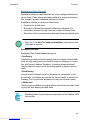
Login Failures
The Cayman software provides the means for assigning passwords to the
Admin or User accounts to control access to the Gateway. Any attempts to
login are given three chances to enter a valid password. The Security Monitoring software records instances where the user fails to enter a valid password.
Logged information includes:
IP source address
Attempt count
Number of attempts
Time at last attempt
MAC Address Spoofing
A MAC (Media Access Control) Address Spoofing Attack can be identified
based on the IP-interface where the illegitimate packet came from. If the
interface that the spoofed packet arrives on does not have the same MAC
address as the legitimate entry in the routing table, then an attack is
logged.
Logged information includes:
IP source address
IP interface
Number of attempts
Time at last attempt
25
Downloaded from www.Manualslib.com manuals search engine
Section 3
General
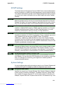
BreakWater Basic Firewall
BreakWater delivers an easily selectable set of pre-configured firewall protection levels. These settings are readily available for simple implementation through Cayman’s embedded web server interface.
BreakWater provides you and your network with:
•
Protection for all LAN users.
•
Elimination of firewall management software on individual PC’s.
•
Immediate protection through three pre-configured firewall levels.
•
Elimination of the complexity associated with developing firewall rules.
See page 69 for How To Configure BreakWater instructions including a table of user tips.
BreakWater Settings
BreakWater Basic Firewall’s three settings are:
ClearSailing
ClearSailing provides protection against network initiated inbound traffic,
while securely passing outbound traffic through the Gateway. In conjunction with Network Address Translation, this setting allows authorized
remote diagnostic support while protecting against undesired inbound
traffic.
SilentRunning
Using this level of firewall protection allows secure transmission of outbound traffic, but disables any attempt for inbound traffic to identify the
Gateway. This is the Internet equivalent of having an unlisted number.
LANdLocked
The third option available turns off all inbound and outbound traffic, isolating the LAN and disabling all WAN traffic.
BreakWater Basic Firewall operates independent of the Gateway’s NAT
functionality.
26
Downloaded from www.Manualslib.com manuals search engine
Section 3
General
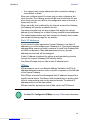
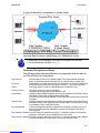
VPN IPSec Pass Through
This Cayman service supports your independent VPN client software in a
transparent manner. Cayman has implemented an Application Layer Gateway (ALG) to support multiple PCs running IP Security protocols.
This feature has three elements:
1. On power up or reset, the address mapping function (NAT) of the Gateway’s
WAN configuration is turned on by default.
2. When you use your third-party VPN application, the Gateway recognizes the
traffic from your client and your unit. It allows the packets to pass through the
NAT “protection layer” via the encrypted IPSec tunnel.
3. The encrypted IPSec tunnel is established “through” the Gateway.
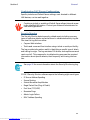
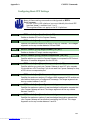
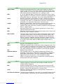
A typical VPN IPSec Tunnel pass through is diagrammed below:
Cayman
Gateway
Typically, no special configuration is necessary to use the IPSec pass
through feature. This feature may need to be disabled for special VPN
clients that are designed to be supported through NAT.
In the diagram, VPN PC clients are shown behind the Cayman Gateway and the secure server is at Corporate Headquarters across the
WAN. You cannot have your secure server behind the Cayman Gateway.
When multiple PCs are starting IPSec sessions, they must be started
one at atime to allow the associations to be created and mapped.
27
Downloaded from www.Manualslib.com manuals search engine
Section 3
General
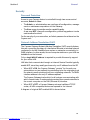
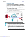
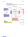
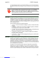
SafeHarbour VPN IPSec Tunnel
SafeHarbour VPN IPSec Tunnel provides a single, encrypted tunnel to be
terminated on the Gateway, making a secure tunnel available for all LANconnected Users. This implementation offers the following:
• Eliminates the need for VPN client software on individual PC’s.
• Reduces the complexity of tunnel configuration.
• Simplifies the ongoing maintenance for secure remote access.
A VPN tunnel is a secure link between two networks interconnected over
an IP network providing a secure, cost-effective alternative to dedicated
leased lines.
SafeHarbour employs VPN standards, including:
• Internet Protocol Security (IPSec) suite, a series of protocols including
encryption, authentication, integrity, and replay protection.
• Internet Key Exchange (IKE), a management protocol of IPSec.
Adherence to VPN standards allows seamless interoperability between a
Cayman Gateway and another standards-based encryptor. SafeHarbour
supports:
•
•
•
Symmetric encryption protocols DES, 3DES, Blowfish, and CAST
Hash algorithms MD5 and SHA1
Diffie-Hellman groups 1, 2, and 5.
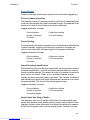
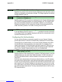
Terms are defined in the Glossary and How To sections.
Encrypted IPSec Tunnel
“RemoteNetTwo”
“HQNetOne”
IP Network
Tunnel Terminates
at Standards-based Gateway
Tunnel Terminates
at Cayman Gateway
SafeHarbour VPN IPSec Tunnel Termination
An important feature of the SafeHarbour VPN IPSec Tunnel is secure
encryption of the configured circuit in both directions.
28
Downloaded from www.Manualslib.com manuals search engine
Section 4
Access the User Interface
Web-based User Interface
Section 4
Access the User Interface
Using the embedded Web-based user interface for the Netopia Caymanseries Gateway you can configure, troubleshoot, and monitor the status of
your Gateway. For COS Version 6.3 the Web-based UI has been modified:
•
•
To accomodate multiple new features of COS 6.3.
To make using the entire facility easier.
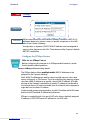
Open the Web Connection
Once your Gateway is powered up, you can use any recent version of the
best-known web browsers that support javascript and Cascading Style
Sheets from any LAN-attached PC or workstation.
The procedure is:
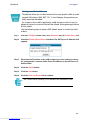
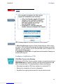
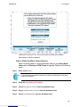
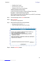
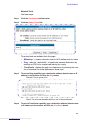
Step 1
Enter the name or IP address of your Cayman Gateway in the Web browser's
window and click Enter.
For example, you would enter http://192.168.1.254 if your Cayman Gateway is
using its default IP address. You can enter http://cayman-2e. (including the final
period) or http://cayman-dsl. if your computer has been configured to obtain its
network configuration from a DHCP server.
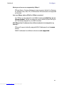
Step 2
If an administrator or user password has been assigned to the Cayman
Gateway, enter Admin or User as the username and the appropriate
password and click OK.
The Cayman Gateway Home page opens.
If the Gateway is not configured, after logon you will see the Quickstart page.
29
Downloaded from www.Manualslib.com manuals search engine
Section 4
Home page
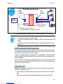
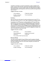
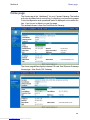
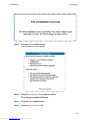
Home page
The Home page is the “dashboard” for your Cayman Gateway. The toolbar
at the top provides links to controlling, configuring, and monitoring pages.
Critical configuration and operational status is displayed in the center section. If you log on as Admin you see this page.
This example screen is from the Dual Ethernet Gateway.
The Home page differs slightly between DSL and Dual Ethernet Gateways.
Home page - User Mode, DSL Gateway
30
Downloaded from www.Manualslib.com manuals search engine
Section 4
Home page
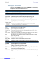
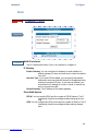
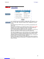
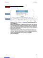
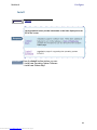
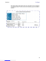
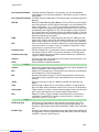
Home page - Information
The Home page’s center section contains a summary of the Gateway’s
configuration settings and operational status.
Summary Information
Field
Status and/or Description
General Information
Hardware
Model number and summary specification
Serial Number Unique serial number, located on label attached to bottom of unit
Software Version
Release and build number of running Cayman Operating System.
Product ID
Refers to internal circuit board series; useful in determining which software
upgrade applies to your hardware type.
Optional (Keyed)
- BreakWater
Firewalll
Indicates which BreakWater Basic Firewall protection level is enabled:
ClearSailing, SilentRunning, or LANdLocked
WAN
Status
Wide Area Network is either Up or Down
IP Address
IP address assigned to the WAN port.
Default Gateway
IP address of the host to which your Gateway sends network traffic when it
can’t find the destination host.
DHCP Client
Default setting lets a WAN host configure the IP address and other network
settings for the WAN interface of your Cayman Gateway.
NAT
On or Off. ON if using Network Address Translation to share the IP address
across many LAN users.
Netmask
Defines the IP subnet for the WAN
DHCP Lease
Expires
Displays the amount of time remaining on current lease
WAN Users
Displays the number of users allotted and the total number available for use.
LAN
IP Address
Internal IP address of the Cayman Gateway.
Netmask
Defines the IP subnet for the LAN
Default is 255.255.255.0 for a Class C device
DHCP Server
On or Off. ON if using DHCP to get IP addresses for your LAN client machines.
DNS
IP address of the Domain Name Server.
Leases in Use
A “lease” is held by each LAN client that has obtained an IP address through
DHCP.
31
Downloaded from www.Manualslib.com manuals search engine
Section 4
Toolbar
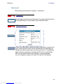
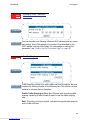
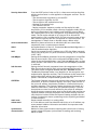
Toolbar
The toolbar is the dark blue bar at the top of the page containing the
major navigation buttons. These buttons are available from almost every
page, allowing you to move freely about the site. The example toolbar
shown below is displayed when you log on as Admin. If you log on as
User, some buttons will not be shown.
Home
Configure
Troubleshoot Security
Install
Quickstart
System Status Passwords
Install Keys
LAN
Network
Tools
Firewall
Install Software
WAN
Diagnostics
IPSec
Advanced
Restart
Help
Security Log
Navigating the Web Interface
Link
Breadcrumb Trail
Response
Comment
The breadcrumb trail is built in the light brown area beneath the toolbar.
As you navigate down a path within the site, the trail is built from left to
right. To return anywhere along the path from which you came, click on
one of the links.
32
Downloaded from www.Manualslib.com manuals search engine
Section 4
Restart
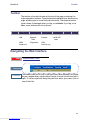
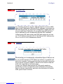
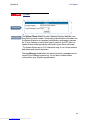
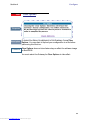
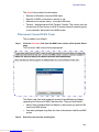
Restart
Button
Restart
Response
Comment
The Restart button on the toolbar allows you to restart the Gateway at
any time. You will be prompted to confirm the restart before any action is
taken. The Restart Confirmation message explains the consequences of
and reasons for restarting the Gateway
33
Downloaded from www.Manualslib.com manuals search engine
Section 4
Link
Restart
Alert Symbol
Response
Comment
The Alert symbol appears in the upper right corner under one of two circumstances:
1. a database change; one in which a change is made to the Gateway’s
configuration. The Alert serves as a reminder that you must Save the
changes and Restart the Gateway before the change will take effect. You
can make many changes on various pages, and even leave the browser
for up to 8 minutes, but if the Gateway is restarted before the changes
are applied, they will be lost. When you click on the Alert symbol, the
Save Changes page appears. Here you can select various options to save
or discard these changes.
2. a security event is logged. If you have Security Monitoring keyed, you
receive Alerts whenever there is an event in the log that has not been
viewed. When you click the Alert symbol the Security Log is displayed
and the Alert clears.
If both types of Alert are triggered, you will need to take action to clear
the first type of Alert before you can see the second Alert.
34
Downloaded from www.Manualslib.com manuals search engine
Section 4
Help
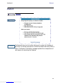
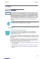
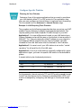
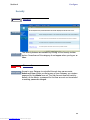
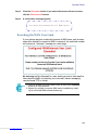
Help
Button
Help
Response
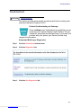
Comment
Context-sensitive Help is provided in Release 6.3. The page shown above
is displayed when you are on the Home page or other transitional pages.
To see a context help page example, go to Security -> Passwords, then
click Help.
35
Downloaded from www.Manualslib.com manuals search engine
Section 4
Configure
Configure
Configure
Button
The Configuration options are presented in the order of likelihood you
will need to use them. Quickstart is typically accessed during the hardware installation and initial configuration phase. Often, these settings
should be changed only in accordance with information from your
Service Provider. LAN and WAN settings are available to fine-tune your
system. Advanced provides some special capabilities typically used for
gaming or small office environments, or where LAN-side servers are
involved.
Comment
This button will not be available if you log on as User.
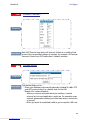
Quickstart
How to Use the Quickstart Page
Quickstart is normally used immediately after the new hardware is
installed. When you are first configuring your Gateway, Quickstart
appears after you log on.
(Once you have configured your Gateway, logging on displays the Home
page. Thereafter, if you need to use Quickstart, choose it from the Configure menu.)
The Quickstart page you see depends on your type of Gateway and the
type of connection to your service provider. You may have one of the following types of connection to your service provider:
•
•
•
DHCP (without PPP) - see “Setup Your Gateway using a DHCP Connection” on page 37
PPP - see “Setup Your Gateway using a PPP Connection” on page 40
Static IP Address - “Setup Your Gateway using a Static IP Address” on
page 41
36
Downloaded from www.Manualslib.com manuals search engine
Section 4
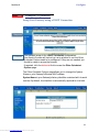
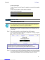
Link
Configure
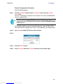
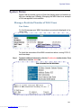
Configure -> Quickstart
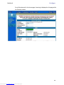
Setup Your Gateway using a DHCP Connection
Response
Comment
This example screen is for a DHCP Quickstart configuration.
Your Service Provider will instruct you as to whether or not the Other
Quickstart Options need to be configured. If they are not needed, you
should be ready to access the Internet.
If required, click the Advanced link to access the Other Quickstart
Options page.
The Other Quickstart Options page allows you to change the System
Name or your Gateway’s Ethernet MAC address.
System Name is your Gateway’s factory identifier combined with its serial
number. By default, this identifier is automatically captured for this field.
37
Downloaded from www.Manualslib.com manuals search engine
Section 4
Configure
Some broadband cable-oriented Service Providers use the System Name as
an important identification and support parameter. If your Gateway is part of
this type of network, do NOT alter the System Name unless specifically
instructed by your Service Provider
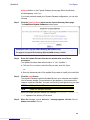
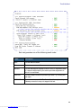
If you need to change either of these fields, use the following procedure.
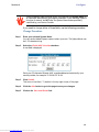
Change Procedure
Step 1
Enter your selected System Name.
You can use the default System name or select your own. The System Name can
be 1-32 characters long.
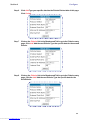
Step 2
Select the Enable MAC Override checkbox.
A new field is displayed.
Enter your 12-character Ethernet MAC override address as instructed by your
service provider, for example: 12 34 AB CD 19 64
Step 3
Click Submit.
This turns on the Alert (“!”) button in the top right corner of the page.
Step 4
Click the Alert button to go to the page to save your changes.
Step 5
Click on the Save and Restart link.
38
Downloaded from www.Manualslib.com manuals search engine
Section 4
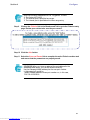
Configure
You will be returned to the Home page. A warning is displayed on this page while
the Gateway restarts.
39
Downloaded from www.Manualslib.com manuals search engine
Section 4
Configure
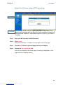
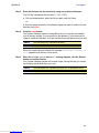
Setup Your Gateway using a PPP Connection
Response
Comment
This example screen is the for a PPP Quickstart configuration. Your
gateway authenticates with the Service Provider equipment using the ISP
Username and Password. These values are given to you by your Service
Provider.
Step 1
Enter your ISP Username and ISP Password.
Step 2
Click Submit.
This turns on the Alert (“!”) button in the top right corner of the page.
Step 3
Click the Alert button to go to the page to save your changes.
Step 4
Click on the Save and Restart link.
You will be returned to the Home page. A warning is displayed on this
page while the Gateway restarts.
40
Downloaded from www.Manualslib.com manuals search engine
Section 4
Configure
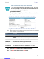
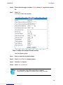
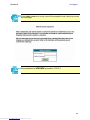
Setup Your Gateway using a Static IP Address
If your service provider supplies you with a static IP address, your Gateway’s Quickstart page will offer the fields required to enter the appropriate information for this type of configuration.
Configuration Procedure
The Quickstart page designed for a static IP address offers the following fields for
you to supply the required information:
Step 1
Enter the values provided by your Internet Service Provider in the Quickstart
fields. Complete the following fields:
Field
Description
WAN IP Address
The IP address assigned to your Cayman Gateway.
WAN IP Netmask
Defines the IP subnet mask for the WAN network connected to your
Gateway.
Default Gateway
IP address of the host to which the Cayman Gateway should send network traffic when it can't find the destination host.
Domain Name
The domain name supplied by your service provider.
Primary DNS
Server Address
The IP address of the primary DNS name server for your network.
Secondary DNS
Server Address
The IP address of the backup DNS name server for your network.
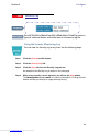
Step 2
Click the Submit button to save the modified configuration.
Step 3
The Alert button appears. Click the Alert button.
41
Downloaded from www.Manualslib.com manuals search engine
Section 4
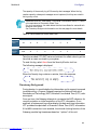
Step 4
Configure
When you see the Save Changes page, click the Save and Restart link to
restart your Cayman Gateway with its new configuration settings.
You will be returned to the Home page. A warning is displayed on this
page while the Gateway restarts.
Step 5
After your Cayman Gateway restarts, use your browser to verify that you
can access the Internet.
Your Cayman Gateway can now use the configured IP parameters
Do NOT confuse this procedure that establishes an IP address for the Gateway’s default IP traffic with configuring multiple static IP addresses used with
the IPMaps feature
42
Downloaded from www.Manualslib.com manuals search engine
Section 4
Configure
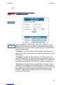
LAN
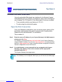
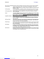
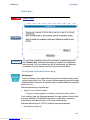
Link
Configure -> LAN
Response
Comment
* Interface Enable: Enables all LAN-connected computers to shared
resources and to connect to the WAN. The Interface should always be
enabled unless you are instructed to disable it by your Service Provider
during troubleshooting.
* IP Address: The LAN IP Address of the Gateway. The IP Address you
assign to your LAN interface must not be used by another device on your
LAN network.
* IP Netmask: Specifies the subnet mask for the TCP/IP network connected to the virtual circuit. The subnet mask specifies which bits of the
32-bit binary IP address represent network information. The default subnet mask for most networks is 255.255.255.0 (Class C subnet mask.)
* Restrictions: Specifies whether an administrator can open a Telnet
connection to the Gateway over the LAN interface in order to monitor
and configure the Gateway. On the LAN Interface, you can enable or disable administrator access. By default, administrative restrictions are
turned off, meaning an administrator can open a Telnet connection
through the LAN Interface.
43
Downloaded from www.Manualslib.com manuals search engine
Section 4
Configure
WAN
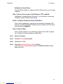
Link
Configure -> WAN
Response
Comment
WAN IP Interfaces
Your IP interfaces are listed. Click on an interface to configure it.
IP Gateway
Enable Gateway: You can configure the Gateway to send packets to a
default gateway if it does not know how to reach the destination host.
Interface Type: If you have PPPoE enabled, you can specify that packets
destined for unknown hosts will be sent to the gateway being
used by the remote PPP peer.. If you select ip-address, you
must enter the IP address of a host on a local or remote network to receive the traffic.
Default Gateway: The IP Address of the default gateway.
Other WAN Options
PPPoE: You can enable PPPoE and the number of PPPoE Sessions. The IP
Interface(s) should be reconfigured after changing this setting.
ATM: You can configure the ATM circuits and the number of Sessions. The IP
Interface(s) should be reconfigured after making changes
here.
44
Downloaded from www.Manualslib.com manuals search engine
Section 4
Configure
Advanced
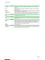
The following are links under Configure -> Advanced:
Link
Comment
Link
Advanced
Selected Advanced options are discussed in the pages that follow. Many
are self-explanatory or are dictated by your service provider.
IP Static Routes
Response
Description
A static route identifies a manually configured pathway to a remote network. Unlike dynamic routes, which are acquired and confirmed periodically from other routers, static routes do not time out. Consequently,
static routes are useful when working with PPP, since an intermittent
PPP link may make maintenance of dynamic routes problematic.
You can configure as many as 16 static IP routes for the Gateway.
45
Downloaded from www.Manualslib.com manuals search engine
Section 4
Link
Configure
IP Static ARP
Response
Description
Link
Your Gateway maintains a dynamic Address Resolution Protocol (ARP)
table to map IP addresses to Ethernet (MAC) addresses. It populates this
ARP table dynamically, by retrieving IP address/MAC address pairs only
when it needs them. Optionally, you can define static ARP entries to
map IP addresses to their corresponding Ethernet MAC addresses.
Unlike dynamic ARP table entries, static ARP table entries do not time
out. The IP address cannot be 0.0.0.0. The Ethernet MAC address entry
is in nn-nn-nn-nn-nn-nn (hexadecimal) format.
Pinholes
Response
Description
Pinholes allow you to transparently route selected types of network traffic, such as FTP requests or HTTP (Web) connections, to a specific host
behind the Gateway. Creating a pinhole allows access traffic originating
from a remote connection (WAN) to be sent to the internal computer
(LAN) that is specified in the Pinhole page.
Contact your Network Administrator for LAN security questions.
Pinholes are common for applications like multiplayer online games.
Refer to software manufacturer application documentation for specific
traffic types and port numbers.
46
Downloaded from www.Manualslib.com manuals search engine
Section 4
Configure
Configure Specific Pinholes
Planning for Your Pinholes
Determine if any of the service applications that you want to provide on
your LAN stations utilize TCP or UDP protocols. If an application does,
then you must configure an Internal Server to implement port forwarding.
This is accessed from the Advanced -> Internal Servers page.
Example: A LAN Requiring Three Pinholes
The procedure on the following pages describes how you set up your NATenabled Cayman Gateway to support three separate applications. This
requires passing three kinds of specific IP traffic through to your LAN.
Application 1: You have a Web server located on your LAN behind your
Cayman Gateway and would like users on the Internet to have access to it.
With NAT “On”, the only externally visible IP address on your network is
the Gateway’s WAN IP (supplied by your Service Provider). All traffic
intended for that LAN Web server must be directed to that IP address.
Application 2: You want one of your LAN stations to act as the “central
repository” for all email for all of the LAN users.
Application 3: One of your LAN stations is specially configured for game
applications. Again, you want this specific LAN station to be dedicated to
games.
A sample table to plan the desired pinholes is:
WAN Traffic Type
Protocol
Pinhole Name
LAN Internal IP Address
Web
TCP
my-webserver
192.168.1.1
Email
TCP
my-mailserver
192.168.1.2
Games
UDP
my-games
192.168.1.3
For this example, Internet protocols TCP and UDP must be passed through
the NAT security feature and the Gateway’s embedded Web (HTTP) port
must be re-assigned by configuring new settings on the Internal Servers
page.
47
Downloaded from www.Manualslib.com manuals search engine
Section 4
Configure
TIPS for making Pinhole Entries
1. If the port forwarding feature is required for Web services, ensure that the
embedded Web server’s port number is re-assigned PRIOR to any Pinhole data entry.
2. Enter data for one Pinhole at a time.
3. Use a unique name for each Pinhole.
If you choose a duplicate name, it will overwrite the previous information without warning.
A diagram of this LAN example is:
Gateway
my-webserver
Internet
192.168.1.1
WAN
Ethernet
Interface
210.219.41.20
LAN
Ethernet
Interface
NAT
my-mailserver
192.168.1.2
NAT Pinholes
Embedded
Web Server
210.219.41.20:8100
my-games
192.168.1.3
48
Downloaded from www.Manualslib.com manuals search engine
Section 4
Configure
Pinhole Configuration Procedure
Use the following steps:
Step 1
From the Configure toolbar button -> Advanced link, select the Internal
Servers link.
Since Port Forwarding is required for this example, the Cayman embedded Web
server is configured first.
The two text boxes, Web (HTTP) Server Port and Telnet Sever Port, on this
page refer to the port numbers of the Cayman Gateway’s embedded administration ports.
To pass Web traffic through to your LAN station(s), select a Web (HTTP)
Port number that is greater than 1024. In this example, you choose 8100.
Step 2
Type 8100 in the Web (HTTP) Server Port text box.
Step 3
Step 4
Click the Submit button.
Step 5
Click Advanced. Select the Pinholes link to go to the Pinhole page.
49
Downloaded from www.Manualslib.com manuals search engine
Section 4
Configure
Step 6
Click Add. Type your specific data into the Pinhole Entries table of this page.
Click Submit.
Step 7
Click on the Pinholes link in the Breadcrumb Trail to go to the Pinholes entry
page. Click Add. Add the next Pinhole. Type the specific data for the second
Pinhole.
Step 8
Click on the Pinholes link in the Breadcrumb Trail to go to the Pinholes entry
page. Click the Add. Add the next Pinhole. Type the specific data for the
third Pinhole.
50
Downloaded from www.Manualslib.com manuals search engine
Section 4
Configure
Note the following parameters for the “my-games” Pinhole:
1. The Protocol ID is UDP.
2. The external port is specified as a range.
3. The Internal port is specified as the lower range entry.
Step 9
Click on the Pinholes link in the Breadcrumb Trail to go to the Pinholes entry
page. Review your entries to be sure they are correct.
Step 10 Click the Alert button.
Step 11 Select the Save and Restart link to complete the entire Pinhole creation task
and ensure that the parameters are properly saved.
REMEMBER: When you have re-assigned the port address for the
embedded Web server, you can still access this facility.
Use the Gateway’s WAN address plus the new port number.
In this example it would be
<WAN Gateway address>:<new port number> or, in this case,
210.219.41.20:8100
51
Downloaded from www.Manualslib.com manuals search engine
Section 4
Configure
Link
IPMaps
Response
Comment
IPMaps supports one-to-one Network Address Translation (NAT) for IP
addresses assigned to servers, hosts, or specific computers on the LAN
side of the Cayman Gateway.
A single static or dynamic (DHCP) WAN IP address must be assigned to
support other devices on the LAN. These devices utilize Cayman’s default
NAT/PAT capabilities.
Configure the IPMaps Feature
FAQs for the IPMaps Feature
Before configuring an example of an IPMaps-enabled network, review
these frequently asked questions.
What are IPMaps and how are they used?
The IPMaps feature allows multiple static WAN IP addresses to be
assigned to the Cayman Gateway.
Static WAN IP addresses are used to support specific services, like a web
server, mail server, or DNS server. This is accomplished by mapping a separate static WAN IP address to a specific internal LAN IP address. All traffic
arriving at the Gateway intended for the static IP address is transferred to
the internal device. All outbound traffic from the internal device appears to
originate from the static IP address.
Locally hosted servers are supported by a public IP address while LAN users
behind the NAT-enabled IP address are protected.
IPMaps is compatible with the use of NAT, with either a statically assigned
IP address or DHCP/PPP served IP address for the NAT table.
52
Downloaded from www.Manualslib.com manuals search engine
Section 4
Configure
What types of servers are supported by IPMaps?
IPMaps allows a Cayman Gateway to support servers behind the Gateway,
for example, web, mail, FTP, or DNS servers. VPN servers are not supported
at this time.
Can I use IPMaps with my PPPoE or PPPoA connection?
Yes. IPMaps can be assigned to the WAN interface provided they are on
the same subnet. Service providers will need to ensure proper routing to
all IP addresses assigned to your WAN interface.
Will IPMaps allow IP addresses from different subnets to be assigned to my
Gateway?
IPMap will support statically assigned WAN IP addresses from the same
subnet.
WAN IP addresses from different subnets are not supported.
53
Downloaded from www.Manualslib.com manuals search engine
Section 4
Configure
IPMaps Block Diagram
The following diagram shows the IPMaps principle in conjunction with
existing Cayman NAT operations:
Cayman Gateway
Static IP Addresses
for IPMaps Applications
WAN Interface
LAN Interface
192.168.1.1
NAT/PAT Table
143.137.50.37
143.137.50.36
143.137.50.37
192.168.1.1
143.137.50.36
192.168.1.2
192.168.1.2
143.137.50.35
...
192.168.1.3
...
143.137.50.35
Static IP Addresses
or
DHCP/PPP Served IP Address
for Cayman’s default NAT/PAT
Capabilities
192.168.1.n
LAN stations with WAN IP traffic
forwarded by Cayman’s IPMaps
LAN stations with WAN IP traffic
forwarded by Cayman’s NAT function.
IPMaps:
One-to-One
Multiple Address Mapping
192.168.1.3
..
.
192.168.1.n
54
Downloaded from www.Manualslib.com manuals search engine
Section 4
Link
Configure
Protocol Lifetimes
Response
Description
Link
Each NAT Protocol map entry will time-out if there is no traffic of that
protocol for the specified number of minutes. For example, UDP entries
time-out if there is no UDP traffic after 6 (default) minutes.
Default Server
Response
Description
This feature allows you to:
* Direct your Gateway to forward all externally initiated IP traffic (TCP
and UDP protocols only) to a default host on the LAN.
* Enable it for certain situations:
– Where you cannot anticipate what port number or packet
protocol an in-bound application might use. For example, some
network games select arbitrary port numbers when a connection
is opened.
– When you want all unsolicited traffic to go to a specific LAN host.
55
Downloaded from www.Manualslib.com manuals search engine
Section 4
Configure
Configure a Default Server
This feature allows you to direct unsolicited or non-specific traffic to a designated LAN station. With NAT “On” in the Gateway, these packets normally would be discarded.
For instance, this could be application traffic where you don’t know (in
advance) the port or protocol that will be utilized. Some game applications
fit this profile.
Use the following steps to setup a NAT default server to receive this information:
Step 1
Select the Configure toolbar button, then Advanced, then the Default Server link.
Step 2
Check the Enable Default Server checkbox. The NAT Server IP Address field
appears.
Step 3
Determine the IP address of the LAN computer you have chosen to receive
the unexpected or unknown traffic. Enter this address in the NAT Server IP
Address field.
Step 4
Click the Submit button.
Step 5
Click the Alert button.
Step 6
Click the Save and Restart link to confirm.
NAT Default Server capability is not available over SafeHarbour IPsec.
56
Downloaded from www.Manualslib.com manuals search engine
Section 4
Configure
Typical Network Diagram
A typical network utilizing the NAT Default Server looks like this:
Internet
Gateway
LAN STN #3
192.168.1.3
WAN
Ethernet
Interface
LAN
Ethernet
Interface
210.219.41.20
NAT
LAN STN #2
192.168.1.2
NAT protected
Embedded
Web Server
210.219.41.20
(Port 80 default)
NAT Pinhole
NAT Default Server
192.168.1.1
NAT Combination Application
Cayman’s NAT security feature allows you to configure a sophisticated LAN
layout that uses both the Pinhole and Default Server capabilities.
With this topology, you configure the embedded administration ports as a
first task, followed by the Pinholes and, finally, the NAT Default Server.
When using both NAT pinholes and NAT Default Server the Gateway works
with the following rules (in sequence) to forward traffic from the Internet
to the LAN:
1. If the packet is a response to an existing connection created by outbound traffic from a LAN PC, forward to that station.
2. If not, check for a match with a pinhole configuration and, if one is found, forward the packet according to the pinhole rule.
3. If there’s no pinhole, the packet is forwarded to the Default Server.
57
Downloaded from www.Manualslib.com manuals search engine
Section 4
Link
Configure
DNS
Response
Description
Your Service Provider may maintain a Domain Name server. If you have
the information for the DNS servers, enter it on the DNS page. If your
Gateway is configured to use DHCP to obtain its WAN IP address, the
DNS information is automatically obtained from that same DHCP
Server.
58
Downloaded from www.Manualslib.com manuals search engine
Section 4
Link
Configure
DHCP Server
Response
Description
Your Gateway can provide network configuration information to computers on your LAN, using the Dynamic Host Configuration Protocol
(DHCP).
If you already have a DHCP server on your LAN, you should turn this
service off.
If you want the Gateway to provide this service, click the Server Mode
pulldown menu, then configure the range of IP addresses that you
would like the Gateway to hand out to your computers.
You can also specify the length of time the computers can use the configuration information; DHCP calls this period the lease time.
Your Service Provider may, for certain services, want to provide configuration from its DHCP servers to the computers on your LANs. In this
case, the Gateway will relay the DHCP requests from your computers to
a DHCP server in the Service Provider's network.
Click the relay-agent and enter the IP address of the Service Provider's
DHCP server in the Server Address field. This address is furnished by the
Service Provider.
59
Downloaded from www.Manualslib.com manuals search engine
Section 4
Link
Configure
SNMP
Response
Description
The Simple Network Management Protocol (SNMP) lets a network
administrator monitor problems on a network by retrieving settings
on remote network devices. The network administrator typically runs
an SNMP management station program on a local host to obtain
information from an SNMP agent. In this case, the Cayman Gateway
is an SNMP agent.
You enter SNMP configuration information on this page.
Your network administrator furnishes the SNMP parameters.
SNMP presents you with a security issue. The community facility of
SNMP behaves somewhat like a password. The community “public”
is a well-known community name. It could be used to examine the
configuration of your Gateway by your service provider or an uninvited reviewer. While Cayman's SNMP implementation does not
allow changes to the configuration, the information can be read
from the Gateway.
If you are strongly concerned about security, you may delete the
“public” community.
60
Downloaded from www.Manualslib.com manuals search engine
Section 4
Link
Configure
Ethernet Bridge
Response
Description
Bridges let you join two local area networks, so that they appear to be
part of the same physical network. As a bridge for protocols other than
TCP/IP, your Gateway keeps track of as many as 255 MAC (Media
Access Control) addresses, each of which uniquely identifies an individual host on a network. Your Gateway uses this bridging table to identify
which hosts are accessible through which of its network interfaces. The
bridging table contains the MAC address of each packet it sees, along
with the interface over which it received the packet. Over time, the
Gateway learns which hosts are available through its WAN port, its LAN
port, and/or its wireless interface.
61
Downloaded from www.Manualslib.com manuals search engine
Section 4
Link
Configure
System
Response
Description
The System Name defaults to your Gateway's factory identifier combined with its serial number. Some cable-oriented Service Providers use
the System Name as an important identification and support parameter. If your Gateway is part of this type of network, do NOT alter the
System Name unless specifically instructed by your Service Provider.
The System Name can be 1-63 characters long; it can include embedded spaces and special characters.
The Log Message Level alters the severity at which messages are collected in the Gateway's system log. Do not alter this field unless
instructed by your Support representative.
62
Downloaded from www.Manualslib.com manuals search engine
Section 4
Link
Configure
Internal Servers
Response
Description
Your Gateway ships with an embedded Web server and support for a
Telnet session, to allow ease of use for configuration and maintenance.
The default ports of 80 for HTTP and 23 for Telnet may be reassigned.
This is necessary if a pinhole is created to support applications using
port 80 or 23. See “Pinholes” on page 46 for more information on Pinhole configuration.
Web (HTTP) Server Port: To reassign the port number used to access
the Cayman embedded Web server, change this value to a value greater
than 1024. When you next access the embedded Cayman Web server,
append the IP address with <port number>, (e.g. Point your browser to
http://210.219.41.20:8080)
Telnet Server Port: To reassign the port number used to access your
Cayman embedded Telnet server, change this value to a value greater
than 1024. When you next access the Cayman embedded Telnet server,
append the IP address with <port number>, (e.g. telnet
210.219.41.20:2323)
63
Downloaded from www.Manualslib.com manuals search engine
Section 4
Link
Configure
Ethernet MAC Address
Override
Response
Description
Link
You can override your Gateway’s Ethernet MAC address with any necessary setting. Some ISPs require your account to be identified by the
MAC address, among other things. For information on setting this
parameter , see “How to Use the Quickstart Page” on page 36.
Traffic Shaping
Response
Description
Traffic shaping controls how much traffic can flow through an Ethernet
interface by limiting the size of the Ethernet pipe. This function is most
suitable for Internet Service Providers.
Enable Traffic Shaping on Port: Each Ethernet port providing traffic
shaping capability is listed. Enable the port to set the traffic shaping
rate.
Rate: This value, in bits per second, indicates the approximate speed at
which traffic will flow.
64
Downloaded from www.Manualslib.com manuals search engine
Section 4
Link
Configure
Clear Options
Response
Description
Comment
To restore the factory configuration of the Gateway, choose Clear
Options. You may want to upload your configuration to a file before
performing this function.
Clear Options does not clear feature keys or affect the software image
or BootPROM.
You must restart the Gateway for Clear Options to take effect.
65
Downloaded from www.Manualslib.com manuals search engine
Section 4
Configure
Security
Button
Security
Response
Description
Link
Description
The Security features are available by clicking on the Security toolbar
button. Some items of this category do not appear when you log on as
User.
Passwords
Access to your Gateway is controlled through two user accounts,
Admin and User. When you first power up your Gateway, you create a
password for the Admin account. The User account does not exist by
default. As the Admin, a password for the User account can be entered
or existing passwords changed.
66
Downloaded from www.Manualslib.com manuals search engine
Section 4
Configure
Create and Change Passwords
You can establish different levels of access security to protect your Cayman Gateway settings from unauthorized display or modification.
• Admin level privileges let you display and modify all settings in the
Cayman Gateway (Read/Write mode). The Admin level password is created when you first access your Gateway.
• User level privileges let you display (but not change) settings of the
Cayman Gateway. (Read Only mode)
To prevent anyone from observing the password you enter, characters in
the old and new password fields are not displayed as you type them.
To display the Passwords window, click the Security toolbar button on the
Home page.
Use the following procedure to change existing passwords or add the User
password for your Cayman Gateway:
Step 1
Select the password type from the Password Level pull-down list.
Choose from Admin or User.
Step 2
If you assigned a password to the Cayman Gateway previously, enter your
current password in the Old Password field.
Step 3
Enter your new password in the New Password field.
Cayman’s rules for a Password are:
67
Downloaded from www.Manualslib.com manuals search engine
Section 4
Configure
•
•
It can have up to eight alphanumeric characters.
It is case-sensitive.
Step 4
Enter your new password again in the Confirm Password field.
You confirm the new password to verify that you entered it correctly the first time.
Step 5
When you are finished, click the Submit button to store your modified
configuration in the Cayman unit’s memory.
Password changes are automatically saved, and take effect immediately.
68
Downloaded from www.Manualslib.com manuals search engine
Section 4
Link
Configure
Firewall
Use a Cayman Firewall
BreakWater Basic Firewall
BreakWater delivers an easily selectable set of pre-configured firewall protection levels. For simple implementation these settings (comprised of
three levels) are readily available through Cayman’s embedded web
server interface.
BreakWater Basic Firewall’s three settings are:
ClearSailing
ClearSailing, BreakWater's default setting, supports both inbound and outbound traffic. It is the only basic firewall setting that fully interoperates
with all other Cayman software features.
SilentRunning
Using this level of firewall protection allows transmission of outbound traffic on pre-configured TCP/UDP ports. It disables any attempt for inbound
traffic to identify the Gateway. This is the Internet equivalent of having an
unlisted number.
LANdLocked
The third option available turns off all inbound and outbound traffic, isolating the LAN and disabling all WAN traffic.
BreakWater Basic Firewall operates independent of the NAT
functionality on the Gateway.
Configuring for a BreakWater Setting
Use these steps to establish a firewall setting:
Step 1
Ensue that you have enabled the BreakWater basic firewall with the
appropriate feature key.
See “Use Cayman Software Feature Keys” on page 93 for reference.
Step 2
Click the Security toolbar button.
Step 3
Click Firewall.
69
Downloaded from www.Manualslib.com manuals search engine
Section 4
Configure
Step 4
Click on the radio button to select the protection level you want. Click
Submit.
Changing the BreakWater setting does not require a restart to take effect. This
makes it easy to change the setting "on the fly,” as your needs change.
TIPS for making your BreakWater Basic Firewall Selection
Application
Select this Level
Typical Internet usage
(browsing, e-mail)
SilentRunning
Multi-player online gaming
ClearSailing
Other Considerations
Set Pinholes; once defined, pinholes will
be active whenever ClearSailing is set.
Restore SilentRunning when finished.
Going on vacation
LANdLocked
Protects your connection while your away.
Finished online use for the
day
LANdLocked
This protects you instead of disconnecting
your Gateway connection.
Chatting online or using
instant messaging
ClearSailing
Set Pinholes; once defined, pinholes will
be active whenever ClearSailing is set.
Restore SilentRunning when finished.
70
Downloaded from www.Manualslib.com manuals search engine
Section 4
Configure
Basic Firewall Background
As a device on the Internet, a Cayman Gateway requires an IP address in
order to send or receive traffic.
The IP traffic sent or received have an associated application port which is
dependent on the nature of the connection request. In the IP protocol
standard the following session types are common applications:
• ICMP
• SNMP
• HTTP
• telnet
• FTP
• DHCP
By receiving a response to a scan from a port or series of ports (which is the
expected behavior according to the IP standard), hackers can identify an
existing device and gain a potential opening for access to an internet-connected device.
To protect LAN users and their network from these types of attacks, BreakWater offers three levels of increasing protection.
The following tables indicate the state of ports associated with session types, both on the WAN side and the LAN side of the Gateway.
This table shows how inbound traffic is treated. Inbound means the traffic is
coming from the WAN into the WAN side of the Gateway.
Gateway: WAN Side
BreakWater Setting >>
Port
ClearSailing
Session Type
SilentRunning
LANdLocked
--------------Port State-----------------------
20
ftp data
Enabled
Disabled
Disabled
21
ftp control
Enabled
Disabled
Disabled
23
telnet external
Enabled
Disabled
Disabled
23
telnet Cayman server
Enabled
Disabled
Disabled
80
http external
Enabled
Disabled
Disabled
80
http Cayman server
Enabled
Disabled
Disabled
67
DHCP client
Enabled
Enabled
Disabled
68
DHCP server
Not Applicable
Not Applicable
Not Applicable
161
snmp
Enabled
Disabled
Disabled
ping (ICMP)
Enabled
Disabled
Disabled
71
Downloaded from www.Manualslib.com manuals search engine
Section 4
Configure
This table shows how outbound traffic is treated. Outbound means the traffic is coming from the LAN-side computers into the LAN side of the Gateway.
Gateway: LAN Side
BreakWater Setting >>
Port
ClearSailing
Session Type
SilentRunning
LANdLocked
--------------Port State-----------------------
20
ftp data
Enabled
Enabled
Disabled
21
ftp control
Enabled
Enabled
Disabled
23
telnet external
Enabled
Enabled
Disabled
23
telnet Cayman server
Enabled
Enabled
Enabled
80
http external
Enabled
Enabled
Disabled
80
http Cayman server
Enabled
Enabled
Enabled
67
DHCP client
Not Applicable
Not Applicable
Not Applicable
68
DHCP server
Enabled
Enabled
Enabled
161
snmp
Enabled
Enabled
Enabled
ping (ICMP)
Enabled
Enabled
WAN - Disabled
LAN Local Address Only
The Gateway’s WAN DHCP client port in SilentRunning mode is enabled. This
feature allows end users to continue using DHCP-served IP addresses from their
Service Providers, while having no identifiable presence on the Internet.
72
Downloaded from www.Manualslib.com manuals search engine
Section 4
Configure
IPSec
Link
Response
Your Gateway supports two mechanisms for IPSec tunnels:
Description
1. IPSec PassThrough supports Virtual Private Network (VPN) clients
running on LAN-connected computers. Normally, this feature is enabled.
However, you can disable it if your LAN-side VPN client includes its own
NAT interoperability option.
2. SafeHarbour VPN IPSec is a keyed feature that enables Gateway-terminated VPN support.
Configure a SafeHarbour VPN
VPN IPSec Tunnel at the Gateway
SafeHarbour VPN IPSec Tunnel provides a single, encrypted tunnel to be
terminated on the Gateway, making a secure tunnel available for all
LAN- connected Users. This implementation offers the following:
•
•
•
Eliminates the need for VPN client software on individual PC’s.
Reduces the complexity of tunnel configuration.
Simplifies the ongoing maintenance for secure remote access.
73
Downloaded from www.Manualslib.com manuals search engine
Section 4
Configure
A typical SafeHarbour configuration is shown below:
Use these Best Practices in establishing your SafeHarbour tunnel.
1. Ensure that the configuration information is complete and accurate
2. Use the Worksheet provided on page 76.
Parameter Description and Setup
The following table describes SafeHarbour’s parameters that are used for
an IPSec VPN tunnel configuration:
Auth Protocol
Authentication Protocol for IP packet header. The three parameter values are
None, Encapsulating Security Payload (ESP) and Authentication Header (AH)
DH Group
Diffie-Hellman is a public key algorithm used between two systems to determine
and deliver secret keys used for encryption. Groups 1, 2 and 5 are supported.
Enable
This toggle button is used to enable/disable the configured tunnel.
Encrypt Protocol
Encryption protocol for the tunnel session.
Parameter values supported include NONE or ESP.
Hard MBytes
Setting the Hard MBytes parameter forces the renegotiation of the IPSec Security
Associations (SAs) at the configured Hard MByte value.
The value can be configured between 1 and 1,000,000 MB and refers to data traffic passed.
Hard Seconds
Setting the Hard Seconds parameter forces the renegotiation of the IPSec Security
Associations (SAs) at the configured Hard Seconds value. The value can be configured between 60 and 1,000,000 seconds
Key Management
The Key Management algorithm manages the exchange of security keys in the
IPSec protocol architecture. SafeHarbour supports the standard Internet Key
Exchange (IKE)
Peer External IP Address The Peer External IP Address is the public, or routable IP address of the remote
gateway or VPN server you are establishing the tunnel with.
Peer Internal IP NetworkThe Peer Internal IP Network is the private, or Local Area Network (LAN) address
of the remote gateway or VPN Server you are communicating with.
74
Downloaded from www.Manualslib.com manuals search engine
Section 4
Configure
Peer Internal IP NetmaskThe Peer Internal IP Netmask is the subnet mask of the Peer Internal IP Network.
PFS DH Group
Perfect Forward Secrecy (PFS) is used during SA renegotiation. When PFS is
selected, a Diffie-Hellman key exchange is required. SafeHarbour supports PFS DH
Groups 1, 2 and 5.
Pre-Shared Key
The Pre-Shared Key is a parameter used for authenticating each side. The value
can be an ASCII or Hex and a maximum of 64 characters. ASCII is case-sensitive.
Pre-Shared Key Type
The Pre-Shared Key Type classifies the Pre-Shared Key. SafeHarbour supports
ASCII or HEX types
Name
The Name parameter refers to the name of the configured tunnel. This is mainly
used as an identifier for the administrator. The Name parameter is an ASCII value
and is limited to 31characters. The tunnel name is the only IPSec parameter that
does not need to match the peer gateway.
Negotiation Method
This parameter refers to the method used during the Phase I key exchange, or IKE
process. SafeHarbour supports Main or Aggressive Mode. Main mode requires 3
two-way message exchanges while Aggressive mode only requires 3 total message exchanges.
SA Encrypt Type
SA Encryption Type refers to the symmetric encryption type. This encryption algorithm will be used to encrypt each data packet. SA Encryption Type values supported include DES, 3DES, CAST and Blowfish.
SA Hash Type
SA Hash Type refers to the Authentication Hash algorithm used during SA negotiation. Values supported include MD5 and SHA1. N/A will display if NONE is chosen for Auth Protocol.
Soft MBytes
Setting the Soft MBytes parameter forces the renegotiation of the IPSec Security
Associations (SAs) at the configured Soft MByte value. The value can be configured between 1 and 1,000,000 MB and refers to data traffic passed. If this value is
not achieved, the Hard MBytes parameter is enforced.
Soft Seconds
Setting the Soft Seconds parameter forces the renegotiation of the IPSec Security
Associations (SAs) at the configured Soft Seconds value. The value can be configured between 60 and 1,000,000 seconds.
75
Downloaded from www.Manualslib.com manuals search engine
Section 4
Configure
IPSec Tunnel Parameter Setup Worksheet
Parameter
Cayman
Peer Gateway
Name
Peer External IP Address
Peer Internal IP Network
Peer Internal IP Netmask
Enable
Encrypt Protocol
None
ESP
Auth Protocol
None
ESP
AH
Key Management
IKE
Pre-Shared Key Type
HEX
ASCII
Pre-Shared Key
Negotiation Method
Main
Aggressive
DH Group
1
2
5
SA Encrypt Type
DES
3DES
CAST
Blowfish
SA Hash Type
N/A
MD5
SHA1
PFS DH Group
Off
1
2
5
Soft MBytes
1 - 1000000
Soft Seconds
60 - 1000000
Hard MBytes
1 - 1000000
Hard Seconds
60 - 1000000
76
Downloaded from www.Manualslib.com manuals search engine
Section 4
Configure
SafeHarbour Tunnel Setup
Use the following tasks to configure an IPSec VPN tunnel on your Cayman
Gateway.
Task 1: Ensure that you have SafeHarbour VPN enabled.
SafeHarbour is a keyed feature. See page 93 for information concerning
installing Cayman Software Feature Keys.
Task2: Complete Parameter Setup Worksheet
IPSec tunnel configuration requires precise parameter set between VPN
devices. The Setup Worksheet facilitates setup and assures that the associated variables are identical.
Task 3: Enable IPSec
IPSec must be enabled on your Gateway to allow further VPN configuration. Perform the following steps to enable IPSec:
Step 1
Browse to Gateway.
Step 2
Click the Security toolbar button.
Step 3
Click the IPSec link.
Step 4
Check the Enable SafeHarbour IPSec checkbox.
Checking this box will automatically display the SafeHarbour IPSec Tunnel
Entry parameters.
77
Downloaded from www.Manualslib.com manuals search engine
Section 4
Configure
Leave the Enable NAT over Tunnel choice as Off unless your network
administrator instructs otherwise.
Task 4: Make the IPSec Tunnel Entries
Enter the initial group of tunnel parameters. Refer to your Setup Worksheet and the Glossary of VPN Terms as required. Perform the following
steps:
Step 1
Enter tunnel Name.
This is the only parameter that does not have to be identical to the peer/
remote VPN device
Step 2
Enter the Peer External IP Address.
Step 3
Select Encryption Protocol from the pulldown menu.
Step 4
Select Authentication Protocol from the pulldown menu.
Step 5
Select Key Management from the pulldown menu.
78
Downloaded from www.Manualslib.com manuals search engine
Section 4
Configure
Step 6
Ensure that the toggle checkbox Enable, which is On by default, remains
On.
Step 7
Click Add.
The Tunnel Details page appears.
Task 5: Make the Tunnel Details entries
Use the following steps:
Step 1
Enter or select the required settings.
Step 2
Click Update. The Alert button appears.
Step 3
Click the Alert button.
Step 4
Click Save and Restart.
Your SafeHarbour IPSec VPN tunnel is fully configured.
Tunnel sessions can only be initiated from the LAN client side.
79
Downloaded from www.Manualslib.com manuals search engine
Section 4
Link
Configure
Security Log
Response
Description
Security Monitoring detects security-related events, including common
types of malicious attacks, and writes them to the security log file.
Using the Security Monitoring Log
You can view the Security Log at any time. Use the following steps:
Step 1
Click the Security toolbar button.
Step 2
Click the Security Log link.
Step 3
Click the Show link from the Security Log tool bar.
An example of the Security Log is shown on the next page.
Step 4
When a new security event is detected, you will see the Alert button.
The Security Alert remains until you view the information. Clicking the Alert
button will take you directly to a page showing the log.
80
Downloaded from www.Manualslib.com manuals search engine
Section 4
Configure
81
Downloaded from www.Manualslib.com manuals search engine
Section 4
Configure
The capacity of the security log is 100 security alert messages. When the log
reaches capacity, subsequent messages are not captured, but they are noted in
the log entry count.
Remember that the “time stamp” is Universal Coordinated Time (UTC) which
is the equivalent of Greenwich Mean Time.
For your convenience, the table below lists the time offsets for various North
American time zones.
See Timestamp Background information on the next page for more details.
Table of Time Offsets (in hours) from GMT
Hawaii
Alaska
Pacific
Mountain
Central
Standard
Time
-10
-9
-8
-7
-6
-5
-4
0
Daylight
Savings
Time
N/A
-8
-7
-6
-5
-4
-3
0
Zone ->
Eastern Atlantic
UTC/GMT
Take the recorded UTC/GMT value and subtract the offset value to get the
time that an event occurred in your system.
To reset this log, select Reset from the Security Monitor tool bar.
The following message is displayed.
When the Security Log contains no entries, this is the response
Timestamp Background
During bootup, to provide better log information and to support improved
troubleshooting, a Cayman Gateway acquires the National Institute of
Standards and Technology (NIST) Universal Coordinated Time (UTC) reference signal.
Once per hour, the Gateway attempts to re-acquire the NIST reference, for
re-synchronization or initial acquisition of the UTC information. Once
acquired, all subsequent log entries display this date and time information.
UTC provides the equivalent of Greenwich Mean Time (GMT) information.
If the WAN connection is not enabled, the internal clocking function of the
Gateway provides log timestamps based on “uptime” of the unit.
82
Downloaded from www.Manualslib.com manuals search engine
Section 4
Configure
Install
Button
Install
Response
Description
From the Install toolbar button you can:
• Install new Operating System Software
• Install new Feature Keys
83
Downloaded from www.Manualslib.com manuals search engine
Section 4
Configure
Install Software
Link
Install Software
Response
Comment
This page allows you to install an updated release of the Cayman
Operating System (COS).
Updating Your Gateway to COS Version 6.3
Cayman Operating System Release 6.3 represents significantly expanded
functionality for your Cayman Gateway. To deliver these important features, the COS 6.3 image is larger than earlier versions and the updating
process is different from earlier procedures. It requires careful attention to
the instruction sequence.
Using the Web Page
You install a new operating system image in your unit from the Cayman
embedded Web server’s Home page. For this process, the computer you
are using to connect to the Cayman Gateway must be on the same local
area network as the Cayman Gateway.
84
Downloaded from www.Manualslib.com manuals search engine
Section 4
Configure
Required Tasks
Task #
Description
Page #
1
Locate and confirm the required files.
86
2
Install and verify the Updater application code.
87
3
Install and verify the COS 6.3 image.
89
Depending on your particular subscriber agreement, you may need to install
other feature key files.
Warnings:
COS 6.3 is NOT SUPPORTED on the following models:
2E with PID of 06xx
2E or 2E-H with internal memory of 2MBytes or less
COS 6.3 provides substantial new flexibility and functionality for your Cayman
Gateway. However, once you have upgraded to this version, you cannot revert
back to a previous release.
85
Downloaded from www.Manualslib.com manuals search engine
Section 4
Configure
Task 1 Required Files
Upgrading to COS 6.3 requires THREE files:
1. Documentation - Software Upgrade Instructions PDF file
2. Updater file
3. Cayman Operating System image
Background
When you downloaded your operating system upgrade from the Cayman
website you downloaded a ZIP file containing these files:
•
•
•
Software Upgrade Instructions PDF file (the document you are reading
now)
Updater file for your particular Gateway
Cayman Operating System image for your particular Gateway
Confirm Updater and COS Image Files
The Updater and COS Image files are specific to the model and the product identification (PID) number.
Step 1
Confirm that you have received the appropriate Updater and COS Image
files using this table:
Model
PID
Updater File
COS 6.3.0R0
Image
3220-H
07xx
u8a110R0.COS
c8a630R0.COS
3220-H
08xx
u8j110R0.COS
c8j630R0.COS
3220-H-W11
08xx
u8w110R0.COS
c8w630R0.COS
3220-H-WRF
08xx
u8w110R0.COS
c8w630R0.COS
2E {see Warnings}
07xx
u8e110R0.COS
c8e630R0.COS
2E-H {see Warnings}
07xx
u8e110R0.COS
c8e630R0.COS
2E-H-W11
09xx
u8ew110R0.COS
c8ew630R0.COS
2E-H-WRF
09xx
u8ew110R0.COS
c8ew630R0.COS
Step 2
Copy the confirmed Updater file to a convenient location on a computer on
your local area network. Be sure that you note the location.
Step 3
Copy the confirmed COS 6.3 file to the same location.
86
Downloaded from www.Manualslib.com manuals search engine
Section 4
Configure
Contact Information
Contact Cayman Technical Support for questions concerning the upgrade
process.
Contact Cayman Sales for specific advanced features.
Use this contact information:
Web Access
http://www.netopia.com/support
Technical Support
510-814-5000 ext 1
Main Telephone
510-814-5100
Task 2 Updater File
Install Updater Application Code
If you are currently running a Cayman Operating System version COS 5.90 or
higher, skip this Task and continue to page 89 for Task 3.
Use these steps to install the Updater software in your Gateway from the
Home page:
Step 1
Open a web connection to your Gateway from a LAN computer.
From a web browser access the URL http://cayman-2E. or http://caymandsl. or http://192.168.1.254.
This Home page is from a Cayman 3220-H Gateway (DSL WAN access).
The Home page for a Cayman 2E-H Gateway (Ethernet WAN access) is similar.
Step 2
If necessary, save the LAN configuration settings on your Cayman Gateway.
If you have not previously saved your configuration (that is, if you are running the
factory default configuration your Cayman Gateway came with), click the
87
Downloaded from www.Manualslib.com manuals search engine
Section 4
Configure
Ethernet button on the Cayman Gateway Home page. When the Ethernet
window appears, click Save.
If you have previously saved your Cayman Gateway configuration, you can skip
this step.
Step 3
Click the Install Software button on the Cayman Gateway Home page.
The Install New Cayman Software window opens.
This page is from a Cayman 3220-H Gateway (DSL WAN access).
The page for a Cayman 2E-H Gateway (Ethernet WAN access) is similar.
Step 4
Enter the Updater filename into the text window with one of these
techniques:
The Updater file name starts with the letter “u“ (for “Updater”).
a. Click the Browse button, select the file you want, and click Open.
-orb. Enter the name and path of the update file you want to install in the text field.
Step 5
Click the Install button.
The Cayman Gateway copies the Updater file from your computer and installs it
into its memory storage. You see a series of dots appear on your screen as the
image is copied and installed. You have the following visual guide from your unit:
3220-H
DSL and Status LED indicators will blink.
2E-H
WAN LED indicator will blink.
When the image has been installed, the message “successful install of
file” appears at the bottom of the screen.
Step 6
When the “Please Click Restart” message appears, click the Restart
button and confirm Restart.
88
Downloaded from www.Manualslib.com manuals search engine
Section 4
Configure
Your Cayman Gateway restarts with its new image. During this step you have the
following visual guide from your unit:
3220-H
DSL and Status LED indicators will blink for 30 seconds or more.
2E-H
WAN LED indicator will blink for 30 seconds or more.
Verify Updater Application Code
To verify that the Updater image has loaded successfully, use the following
steps:
Step 7
Open a web connection to your Cayman Gateway from the computer on
your LAN; return to the Home page and select the Monitor button.
Step 8
Under the General toolbar, select the Overview link.
Updater version 1.1
2002
Verify
2002
This page is from a Cayman 3220-H Gateway (DSL WAN access).
The page for a Cayman 2E-H Gateway (Ethernet WAN access) is similar.
Step 9
Verify that the Cayman Gateway is running Updater version 1.1.
If the Updater is not running, the screen will show your COS version instead. If
your COS version is earlier than 5.9, return to Task 1 and retry the installation.
Task 3 COS 6.3 Image File
Install the COS 6.3 Image
The COS installation process is similar to the Updater installation.
To install the COS 6.3 software in your Cayman Gateway from the Home
Page use the following steps:
Step 1
Open a web connection to your Cayman Gateway from the computer on
your LAN.
Step 2
Click the Install Software button on the Cayman Gateway Home page.
The Install New Cayman Software window opens.
89
Downloaded from www.Manualslib.com manuals search engine
Section 4
Step 3
Configure
Enter the filename into the text box by using one of these techniques:
The COS file name starts with the letter “c” (for “COS”).
a. Click the Browse button, select the file you want, and click Open.
-orb. Enter the name and path of the software image you want to install in the text
field and click Open.
Step 4
Click the Install button.
The Cayman Gateway copies the image file from your computer and installs it
into its memory storage. You see a series of dots appear on your screen as the
image is copied and installed. You have the following visual guide from your unit:
3220-H
DSL and Status LED indicators will blink.
2E-H
WAN LED indicator will blink.
When the image has been installed, the message “successful install of
file” appears at the bottom of the screen.
Step 5
When the “Please Click Restart” message appears, click the Restart
button and confirm Restart.
Your Cayman Gateway restarts with its new image. During this step you receive
the following visual guide from your unit:
3220-H
DSL and Status LED indicators will blink for 30 seconds or more.
2E-H
WAN LED indicator will blink for 30 seconds or more.
90
Downloaded from www.Manualslib.com manuals search engine
Section 4
Configure
Verify the COS 6.3 Image
To verify that the COS 6.3 image has loaded successfully, use the following
steps:
Step 1
Open a web connection to your Cayman Gateway from the computer on
your LAN and return to the Home page.
The username admin (or user) is now a required field for logging onto the web
server. In earlier releases, only the password was required.
For COS 6.3 you now have a new layout. The screen shown below is from
a Cayman 3220-H.
1
2
NOTES:
1. Extensive configuration and status information is now available from the
Home page.
2. Verify COS 6.3
Step 2
Verify that your Software Version is COS 6.3.
91
Downloaded from www.Manualslib.com manuals search engine
Section 4
Configure
If your admin password is not set, you will be prompted to set it before you reach
the Home page.
This completes the UPGRADE process for COS 6.3.
92
Downloaded from www.Manualslib.com manuals search engine
Section 4
Configure
Install Keys
Install Keys
Link
Response
You can obtain advanced product functionality by employing a software Feature Key. Software feature keys are specific to a Gateway's
serial number. Once the feature key file is installed and the Gateway
is restarted, the new feature's functionality becomes enabled.
Comment
Use Cayman Software Feature Keys
Background
Cayman Gateway users obtain advanced product functionality by installing a software feature key. This concept utilizes a specially constructed and
distributed file (referred to as a feature key) to enable additional capability
within the unit.
Software feature key properties are:
•
Specific to a unit’s serial number
–
They will not be accepted on a platform with another serial number.
Once installed, and the Gateway restarted, the new feature’s functionality
becomes available. This allows full access to configuration, operation,
maintenance and administration of the new enhancement.
Software feature keys for COS 6.3 enable these enhancements:
•
Security Monitoring Log
93
Downloaded from www.Manualslib.com manuals search engine
Section 4
Configure
•
•
•
BreakWater Basic Firewall
BarrierReef Advanced Firewall
SafeHarbour IPSec Tunnel at the Gateway
Obtaining Software Feature Keys
Contact your Service Provider to acquire a Software Feature Key.
Procedure - Install a New Feature Key File
With the appropriate feature key file resident on your LAN PC, use the steps
listed below to enable a new function.
Step 1
From the Home page, click the Install toolbar button.
Step 2
Click Install Keys
The Install Key File page appears.
Step 3
Enter the feature key file name in the input Text Box.
•
•
Step 4
Browse your drive for the file, or
Type the full path and file name in the Text Box.
Click the Install Keys button.
94
Downloaded from www.Manualslib.com manuals search engine
Section 4
Configure
Step 5
Click the Restart toolbar button.
The Confirmation screen appears.
Step 6
Click the Restart the Gateway link to confirm.
To check your installed features:
Step 1
Click the Install toolbar button.
Step 2
Click the List of Features link.
95
Downloaded from www.Manualslib.com manuals search engine
Section 4
Configure
The System Status page appears with the information from the features
link displayed below. You can check that the feature you just installed is
enabled.
96
Downloaded from www.Manualslib.com manuals search engine
Troubleshoot
Troubleshoot
Button
Troubleshoot
This section provides some specific procedures and tips for working with
important features of Cayman OS 6.3.
Perform Troubleshooting on Gateways
There are three major Troubleshooting capabilities you can
access via your Cayman Gateway’s web interface. The procedures for using them are discussed here. In the event of a
problem with your system, your Service Provider may
request this information.
Automated Multi-Layer Diagnostics
Step 1
Click the Troubleshoot toolbar button.
Step 2
Click the Diagnostics link.
Step 3
Click the Run Diagnostics link.
97
Downloaded from www.Manualslib.com manuals search engine
Troubleshoot
Each test generates one of the following result codes:
CODE
Description
PASS
The test was successful.
FAIL
The test was unsuccessful.
SKIPPED
The test was skipped because a test on which it depended failed,
or it was not supported by the service provider equipment to
which it is connected.
PENDING
The test timed out without producing a result. Try running the
test again.
WARNING
The test was unsuccessful. The Service Provider equipment your
Gateway connects to may not support this test.
98
Downloaded from www.Manualslib.com manuals search engine
Troubleshoot
Network Tools
Use these steps:
Step 1
Click the Troubleshoot toolbar button.
Step 2
Click the Network Tools link.
Three test tools are available from this page.
Step 3
•
NSLookup - converts a domain name to its IP address and vice versa.
•
Ping - tests the “reachability” of a particular network destination by
sending an ICMP echo request and waiting for a reply.
•
TraceRoute - displays the path to a destination by showing the number of hops and the router addresses of these hops.
To use the Ping capability, type a destination address (domain name or IP
address) in the text box and click the Ping button.
Example: Ping to grosso.com.
Result: The host was reachable with four out of five packets sent.
Step 4
To use the TraceRoute capability, type a destination address (domain name
or IP address) in the text box and click the TraceRoute button.
99
Downloaded from www.Manualslib.com manuals search engine
Troubleshoot
Example: Show the path to the grosso.com site.
Result: It took 20 hops to get to the grosso.com web site.
Step 5
To use the NSLookup capability, type an address (domain name or IP
address) in the text box and click the NSLookup button
Example: Show the IP Address for grosso.com
Result: The DNS Server doing the lookup is displayed in the Server: and
Address: fields. If the Name Server can find your entry in its table, it is displayed
in the Name: and Address: fields.
100
Downloaded from www.Manualslib.com manuals search engine
System Status
System Status
System Status provides a group of links that display status and statistics to
help you manage your Gateway. Managing the WAN Users is an example
of the management tools available.
Manage a Restricted Number of WAN Users
User Status
On the Home page your WAN User status is prominently displayed in the
center area.
To check the user status of the WAN connections when running COS 6.3,
use these steps:
Step 1
To obtain additional information, click the Troubleshoot toolbar button. From
WAN Users, click the Show link.
101
Downloaded from www.Manualslib.com manuals search engine
System Status
The Show link provides this information:
•
Number of allowed concurrent WAN users
•
Number of WAN connections currently in use
•
Address and computer name - of current LAN users
•
Timeout - displays status of Idle Timeout Counter. The current user has
this amount of time (from an initial 20 minute interval) remaining prior
to an automatic disconnect from WAN access.
Disconnect Current WAN Users
The procedure is as follows:
Step 1
Click the Disconnect link from the WAN Users section of the System Status
page.
The Disconnect WAN/Internet Users page appears
The Admin and User level password accounts have different privileges
regarding the Disconnect WAN Users function. They are listed below:
Step 2
•
Admin level privileges allow the Admin to disconnect any and all LAN
users from WAN access.
•
User level privileges only allow the User to disconnect itself from WAN
access.
Select the user from the scrolling list.
102
Downloaded from www.Manualslib.com manuals search engine
System Status
Step 3
Click the Disconnect button. If you want to disconnect all users at once,
click the Disconnect All button.
Step 4
A confirmation message appears.
You have disconnected all WAN users
Exceeding the WAN User Limit
If your system supports a restricted number of WAN users, web browser
users who attempt to access the WAN in excess of the restricted number
will receive an “intercept” message on a web page.
No message will be displayed to a user seeking access to other applications requiring WAN connectivity (such as email, instant messaging,
remote access, FTP, or telnet).
1. Even with limited concurrent WAN access, all users have unlimited
access to all LAN resources.
2. Support for multiple concurrent WAN users is available by installing an Unlimited WAN software feature key.
103
Downloaded from www.Manualslib.com manuals search engine
Appendix A
Overview
Tour: Command Line Interface
Appendix A
Overview
The Cayman Gateway operating software includes a command line interface (CLI)
that lets you access your Cayman Gateway over a telnet or console connection.
You can use the command line interface to enter and update the unit’s configuration settings, monitor its performance, and restart it.
The CLI has two major command modes: SHELL and CONFIG. Summary tables
that list the commands are provided below. Details of the entire command set follow in this section.
SHELL Commands
Command
Status and/or Description
arp
send ARP request
atmping
send ATM OAM loopback (DSL only)
clear
erase all stored configuration information
configure
set the unit’s options
diagnose
run the automatic self-test
download
download the config file
help
get more information on a command: “help all” or “help help”
install
download and program an image into flash
log
add a message to the diagnostic log
loglevel
report or change diagnostic log level
netstat
show IP information
nslookup
send DNS query for host
ping
send ICMP echo request
quit
quit this shell
reset
reset subsystems
restart
restart the Gateway
show
display specific system information
start
start subsystem
status
display basic status of Gateway
telnet
telnet to a remote host
traceroute
send traceroute probes
upload
upload config file
who
show who is using the shell
wireless
execute wireless TEACH or LEARN
104
Downloaded from www.Manualslib.com manuals search engine
Appendix A
Overview
CONFIG Commands
Command
Verbs
Status and/or Description
set
Set configuration data
define
Define environment data
delete
Delete configuration list data
view
View configuration data
script
Print configuration data
help
Help command option
save
Save configuration data
Keywords
system
Gateway’s system options
pppoe
PPP over Ethernet options
trafficshape
Traffic shaping options
dmt
DMT ADSL options (DSL only)
atm
ATM options (DSL only)
bncp
Bridge CP options (DSL only)
ip
TCP/IP protocol options
ip-maps
IPMaps options
dhcp
Dynamic Host Configuration Protocol options
nat-default
Network Address Translation default options
dns
Domain Name System options
bridge
Bridge options
snmp
Simple Network Management Protocol options
ppp
Peer-to-Peer Protocol options
pinhole
Pinhole options
security
Security options
servers
Internal Server options
ethernet-MACoverride
Override the ethernet MAC address (2E only)
validate
Validate configuration settings
preference
Shell environment settings
Command
Utilities
top
Go to top level of configuration mode
quit
Exit from configuration mode; return to shell mode
exit
Exit from configuration mode; return to shell mode
105
Downloaded from www.Manualslib.com manuals search engine
Appendix A
Starting and Ending a CLI Session
Starting and Ending a CLI Session
There are two ways to open a CLI session:
1. Open a telnet connection from a workstation on your network
2. Connect a terminal to the Maintenance Port located on the rear panel
of the Cayman Gateway.
Connecting from telnet
You initiate a telnet connection by issuing the following command from an IP
host that supports telnet, for example, a personal computer running a telnet
application such as NCSA Telnet.
BOTH
telnet <ip_address>
You must know the IP address of the Cayman Gateway before you can make a telnet connection to it. By default, your Cayman Gateway uses 192.168.1.254 as
the IP address for its LAN interface. You can use a Web browser or the maintenance console to configure the Cayman Gateway IP address.
Connecting from the Maintenance Console Port
You can connect a terminal or terminal emulator to the maintenance console port
on the Cayman Gateway to configure, administer, and monitor your Cayman
Gateway.
The settings for your terminal emulator are:
•
Speed: 9600 bps
•
Parity: None
•
Databits: 8
•
Stopbits: 1
•
Duplex: Full
•
Flow Control: None
The console interface uses the same command line interface as the telnet interface.
Logging In
The command line interface log-in process emulates the log-in process for a UNIX
host. To logon, enter the username (either admin or user), and your password.
•
Entering the administrator password lets you display and update all Cayman
Gateway settings.
•
Entering a user password lets you display (but not update) Cayman Gateway
settings.
106
Downloaded from www.Manualslib.com manuals search engine
Appendix A
Using the CLI Help Facility
When you have logged in successfully, the command line interface lists the username and the security level associated with the password you entered in the diagnostic log.
Ending a CLI Session
You end a command line interface session by typing quit from the SHELL node
of the command line interface hierarchy.
Saving Settings
The save command saves the working copy of the settings to the Gateway. The
Gateway automatically validates its settings when you save and displays a warning message if the configuration is not correct.
Using the CLI Help Facility
The help command lets you display on-line help for SHELL and CONFIG commands. To display a list of the commands available to you from your current location within the command line interface hierarchy, enter help.
To obtain help for a specific CLI command, type help <command>. You can
truncate the help command to h or a question mark when you request help for a
CLI command.
About SHELL Commands
You begin in SHELL mode when you start a CLI session. SHELL mode lets you perform the following tasks with your Cayman Gateway:
•
Monitor its performance
•
Display and reset Gateway statistics
•
Issue administrative commands to restart Cayman Gateway functions
SHELL Prompt
When you are in SHELL mode, the CLI prompt is the name of the Cayman Gateway followed by a right angle bracket (>). For example, if you open a CLI connection to the Cayman Gateway named “Coconut,” you would see Coconut> as
your CLI prompt.
SHELL Command Shortcuts
You can truncate most commands in the CLI to their shortest unique string. For
example, you can use the truncated command q in place of the full quit command to exit the CLI. However, you would need to enter rese for the reset
command, since the first characters of reset are common to the restart
command.
107
Downloaded from www.Manualslib.com manuals search engine
Appendix A
SHELL Commands
The only command you cannot truncate is restart. To prevent accidental interruption of communications, you must enter the restart command in its
entirety.
You can use the Up and Down arrow keys to scroll backward and forward through
recent commands you have entered. Alternatively, you can use the !! command
to repeat the last command you entered.
Platform Convention
For each Shell and Config command, an “Index Tab” shows which platform(s) the
command supports. For example
BOTH
arp nnn.nnn.nnn.nnn
Both the Cayman 3220-H and 2E-H platforms use this command.
DSL
atmping vpi vci [ segment | end-to-end ]
The Cayman 3220-H platform uses this command.
ENET
reset ppp [enet-B]
The Cayman 2E-H platform uses this command.
SHELL Commands
BOTH
arp nnn.nnn.nnn.nnn
Sends an Address Resolution Protocol (ARP) request to match the
nnn.nnn.nnn.nnn IP address to an Ethernet hardware address.
DSL
atmping vpi vci [ segment | end-to-end ]
Lets you check the ATM connection reachability and network connectivity. This
command sends five Operations, Administration, and Maintenance (OAM) loopback calls to the specified vpi/vci destination. There is a five second total timeout
interval.
Use the segment argument to ping a neighbor switch.
Use the end-to-end argument to ping a remote end node
BOTH
clear [yes]
Clears the configuration settings in a Cayman Gateway. If you do not use the
optional yes qualifier, you are prompted to confirm the clear command.
108
Downloaded from www.Manualslib.com manuals search engine
Appendix A
BOTH
SHELL Commands
configure
Puts the command line interface into Configure mode, which lets you configure
your Cayman Gateway with Config commands. Config commands are described
starting on page 105.
BOTH
diagnose
Runs a diagnostic utility to conduct a series of internal checks and loopback tests
to verify network connectivity over each interface on your Cayman Gateway. The
console displays the results of each test as the diagnostic utility runs. If one test is
dependent on another, the diagnostic utility indents its entry in the console window. For example, the diagnostic utility indents the Check IP connect to Ethernet
(LAN) entry, since that test will not run if the Check Ethernet LAN Connect test
fails.
Each test generates one of the following result codes:
BOTH
CODE
Description
PASS
The test was successful.
FAIL
The test was unsuccessful.
SKIPPED
The test was skipped because a test on
which it depended failed.
PENDING
The test timed out without producing a
result. Try running the test again.
download [-fw –key server_address] [filename] [confirm]
With no flags set, this command installs a file of configuration parameters into the
Cayman Gateway from a TFTP (Trivial File Transfer Protocol) server. The TFTP
server must be accessible on your Ethernet network.
With the –fw flag set, downloads a new firewall text configuration to the Gateway.
With the –key flag set, downloads a new feature key to the Gateway.
You can include one or more of the following arguments with the download command. If you omit arguments, the console prompts you for this information.
•
The server_address argument identifies the IP address of the TFTP server
from which you want to copy the Cayman Gateway configuration file.
•
The filename argument identifies the path and name of the configuration
file on the TFTP server.
•
If you include the optional confirm keyword, the download begins as soon as
all information is entered.
109
Downloaded from www.Manualslib.com manuals search engine
Appendix A
BOTH
SHELL Commands
install [server_address] [filename] [confirm]
Downloads a new version of the Cayman Gateway operating software from a
TFTP (Trivial File Transfer Protocol) server, validates the software image, and programs the image into the Cayman Gateway memory. After you install new operating software, you must restart the Cayman Gateway.
The TFTP server must be accessible on your Ethernet network. The
server_address argument identifies the IP address of the TFTP server on which
your Cayman Gateway operating software is stored. The filename argument
identifies the path and name of the operating software file on the TFTP server.
If you include the optional confirm keyword, you will not be prompted to identify a TFTP server or file name. Your Cayman Gateway begins the software installation using its default boot settings.
.
BOTH
log message_string
Adds the message in the message_string argument to the Cayman Gateway
diagnostic log.
BOTH
loglevel [level]
Displays or modifies the types of log messages you want the Cayman Gateway to
record. If you enter the loglevel command without the optional level argument, the command line interface displays the current log level setting.
You can enter the loglevel command with the level argument to specify the
types of diagnostic messages you want to record. All messages with a level number equal to or greater than the level you specify are recorded. For example, if
you specify loglevel 3, the diagnostic log will retain high-level informational messages (level 3), warnings (level 4), and failure messages (level 5).
Use the following values for the level argument:
BOTH
•
1 or low – Low-level informational messages or greater; includes trivial status
messages.
•
2 or medium – Medium-level informational messages or greater; includes status messages that can help monitor network traffic.
•
3 or high – High-level informational messages or greater; includes status
messages that may be significant but do not constitute errors.
•
4 or warning – Warnings or greater; includes recoverable error conditions
and useful operator information.
•
5 or failure – Failures; includes messages describing error conditions that
may not be recoverable.
netstat -i
Displays the IP interfaces for your Cayman Gateway.
110
Downloaded from www.Manualslib.com manuals search engine
Appendix A
BOTH
SHELL Commands
netstat -r
Displays the IP routes stored in your Cayman Gateway.
BOTH
nslookup { hostname | ip_address }
Performs a domain name system lookup for a specified host.
BOTH
•
The hostname argument is the name of the host for which you want DNS
information; for example, nslookup klaatu.
•
The ip_address argument is the IP address, in dotted decimal notation, of
the device for which you want DNS information.
ping [-s size] [-c count]{ hostname | ip_address }
Causes the Cayman Gateway to issue a series of ICMP Echo requests for the
device with the specified name or IP address.
•
The hostname argument is the name of the device you want to ping; for
example, ping ftp.cayman.com.
•
The ip_address argument is the IP address, in dotted decimal notation, of
the device you want to locate. If a host using the specified name or IP address
is active, it returns one or more ICMP Echo replies, confirming that it is accessible from your network.
•
The -s size argument lets you specify the size of the ICMP packet.
•
The -c count argument lets you specify the number of ICMP packets generated for the ping request.
You can use the ping command to determine whether a hostname or IP address
is already in use on your network. You cannot use the ping command to ping the
Cayman Gateway’s own IP address.
BOTH
quit
Exits the Cayman Gateway command line interface.
BOTH
reset arp
Clears the Address Resolution Protocol (ARP) cache on your unit.
DSL
reset atm
Resets the ATM statistics to zero.
BOTH
reset crash
Clears crash-dump information, which identifies the contents of the Cayman
Gateway registers at the point of system malfunction.
111
Downloaded from www.Manualslib.com manuals search engine
Appendix A
ENET
SHELL Commands
reset dhcp client release { B | all }
Releases the DHCP lease the Gateway is currently using to acquire the IP settings
for its WAN (Ethernet B) port.
DSL
reset dhcp client release [ vcc-id ]
Releases the DHCP lease the Cayman 3220-H is currently using to acquire the IP
settings for the specified DSL port. The vcc-id identifier is a letter in the rang BI. Enter the reset dhcp client release without the variable to see the
letter assigned to each virtual circuit.
ENET
reset dhcp client renew { B | all }
Renews the DHCP lease the Gateway is currently using to acquire the IP settings
of its WAN (Ethernet B) port.
DSL
reset dhcp client renew [ vcc-id ]
Releases the DHCP lease the Cayman 3220-H is currently using to acquire the IP
settings for the specified DSL port. The vcc-id identifier is a letter in the rang BI. Enter the reset dhcp client release without the variable to see the
letter assigned to each virtual circuit.
BOTH
reset dhcp server
Clears the DHCP lease table in the Cayman Gateway.
DSL
reset dsl
Resets any open DSL connection.
BOTH
reset enet
Resets Ethernet statistics to zero
BOTH
reset hosts
Clears all entries in the host name table. Thereafter, when PCs configured as
DHCP clients use the Gateway, new entries will be rebuilt. DHCP serving must be
enabled.
BOTH
reset ipmap
Clears the IPMap table (NAT).
BOTH
reset log
Rewinds the diagnostic log display to the top of the existing Cayman Gateway
diagnostic log. The reset log command does not clear the diagnostic log. The
next show log command will display information from the beginning of the log
file.
ENET
reset ppp [enet-B]
Resets the point-to-point connection over the WAN interface. When you issue a
reset ppp command, the Cayman 2E-H closes any PPP session (including PPP
over Ethernet).
112
Downloaded from www.Manualslib.com manuals search engine
Appendix A
DSL
SHELL Commands
reset ppp vccn
Resets the point-to-point connection over the specified virtual circuit. This command only applies to virtual circuits that use PPP framing.
BOTH
reset security-log
Clears the security monitoring log to make room to capture new entries.
BOTH
reset wan-users [all | ip-address]
This function disconnects the specified WAN User to allow for other users to
access the WAN. This function is only available if the number of WAN Users is
restricted and NAT is on. Use the all parameter to disconnect all users. If you
logon as Admin you can disconnect any or all users. If you logon as User, you can
only disconnect yourself.
BOTH
restart [seconds]
Restarts your Cayman Gateway. If you include the optional seconds argument,
your Cayman Gateway will restart when the specified number of seconds have
elapsed. You must enter the complete restart command to initiate a restart.
DSL
show atm [all]
Displays ATM statistics for 3220-H unit. The optional all argument displays a
more detailed set of ATM statistics.
BOTH
show bridge interfaces
Displays bridge interfaces maintained by the Cayman Gateway.
BOTH
show bridge table
Displays the bridging table maintained by the Cayman Gateway.
BOTH
show crash
Displays the most recent crash information, if any, for your Cayman Gateway.
BOTH
show dhcp agent
Displays the DHCP relay-agent leases being administered by your Cayman Gateway.
BOTH
show dhcp client
Displays the DHCP address information being used by your Cayman Gateway for
each WAN interface.
BOTH
show dhcp server leases [ used | free ]
Displays the DHCP leases stored in RAM by your Cayman Gateway. You can
include the used argument to see the list of DHCP leases that are in use or that
have been used since your Cayman Gateway was restarted. You can include the
free argument to see the list of DHCP leases that are available for use.
113
Downloaded from www.Manualslib.com manuals search engine
Appendix A
BOTH
SHELL Commands
show dhcp server store
Displays the DHCP leases stored in NVRAM by your Cayman Gateway.
DSL
show dsl
Displays DSL port statistics, such as upstream and downstream connection rates
and noise levels.
BOTH
show enet
Displays the Ethernet statistics for your Cayman Gateway.
BOTH
show features
Show all keyed features and whether or not they are enabled. If the key is not permanent, it shows the expiration date.
BOTH
show hosts
Displays the IP address and (computer) host name in the host name table for each
LAN-side computer. The host name table is built by the Gateway as its DHCP
server serves IP addresses to LAN-side computers trying to access the WAN
through the Gateway.
BOTH
show ip arp
Displays the Ethernet address resolution table stored in your Cayman Gateway.
BOTH
show ip firewall
Shows statistics for the BreakWater Firewall.
BOTH
show ip igmp
Displays the contents of the IGMP Group Address table and the IGMP Report
table maintained by your Cayman Gateway.
BOTH
show ip interfaces
Displays the IP interfaces for your Cayman Gateway.
BOTH
show ip ipsec
Shows statistics for the SafeHarbour IPSec tunnel.
BOTH
show ip routes
Displays the IP routes stored in your Cayman Gateway.
BOTH
show log
Displays blocks of information from the Cayman Gateway diagnostic log. To see
the entire log, you can repeat the show log command or you can enter show
log all.
114
Downloaded from www.Manualslib.com manuals search engine
Appendix A
BOTH
SHELL Commands
show memory [all]
Displays memory usage information for your Cayman Gateway. If you include the
optional all argument, your Cayman Gateway will display a more detailed set of
memory statistics.
ENET
show ppp [{ stats | lcp | ipcp | lastconnect }]
Displays information about open PPP links. You can display a subset of the PPP
statistics by including an optional stats, lcp, ipcp, or lastconnect argument for the show ppp command.
DSL
show ppp [{ stats | lcp | ipcp | lastconnect }] [vccn]
Displays information about open PPP links. You can display a subset of the PPP
statistics by including an optional stats, lcp, ipcp, or lastconnect argument for the show ppp command. The optional vccn argument lets you
specify the virtual circuit for which you want statistics.
BOTH
show pppoe
Displays status information for each PPP socket, such as the socket state, service
names, and host ID values.
BOTH
show security-log
Displays up to 100 security-related events stored in the log.
BOTH
show status
Displays the current status of a Cayman Gateway, the device's hardware and software revision levels, a summary of errors encountered, and the length of time the
Cayman Gateway has been running since it was last restarted. Identical to the
status command.
BOTH
show wan-users [all]
Without the all parameter displays the number of concurrent WAN Users and the
total number allowed. With the all parameter specified, displays information
about each connected WAN User, including its IP address and idle time before
automatic disconnect. This function is only available if the number of WAN Users
is restricted and NAT is on.
BOTH
show wireless
Displays status and statistics information for the wireless interface on the Gateway.
ENET
start ppp
Opens a PPP link (typically PPP over Ethernet).
115
Downloaded from www.Manualslib.com manuals search engine
Appendix A
DSL
SHELL Commands
start ppp vccn
Opens a PPP link on the specified virtual circuit.
BOTH
status
Displays the current status of a Cayman Gateway, the device's hardware and software revision levels, a summary of errors encountered, and the length of time the
Cayman Gateway has been running since it was last restarted. Identical to the
show status command.
BOTH
telnet { hostname | ip_address } [port]
Lets you open a telnet connection to the specified host through your Cayman
Gateway.
• The hostname argument is the name of the device to which you want to
connect; for example, telnet ftp.cayman.com.
• The ip_address argument is the IP address, in dotted decimal notation, of
the device to which you want to connect.
• The port argument is the number of t he port over which you want to open
a telnet session.
BOTH
traceroute { hostname | ip_address }
Traces the route between the Cayman Gateway and the specified host.
• The hostname argument is the name of the device you want to trace; for
example, traceroute ftp.cayman.com.
• The ip_address argument is the IP address, in dotted decimal notation, of
the device you want to trace.
BOTH
upload [server_address] [filename] [confirm]
Copies the current configuration settings of the Cayman Gateway to a TFTP (Trivial File Transfer Protocol) server. The TFTP server must be accessible on your Ethernet network. The server_address argument identifies the IP address of the
TFTP server on which you want to store the Cayman Gateway settings. The
filename argument identifies the path and name of the configuration file on
the TFTP server. If you include the optional confirm keyword, you will not be
prompted to identify a TFTP server or file name.
BOTH
who
Displays the names of the current shell users.
116
Downloaded from www.Manualslib.com manuals search engine
Appendix A
About CONFIG Commands
About CONFIG Commands
You reach the configuration mode of the command line interface by typing configure (or any truncation of configure, such as c or config) at the CLI
SHELL prompt.
CONFIG Mode Prompt
When you are in CONFIG mode, the CLI prompt consists of the name of the Cayman Gateway followed by your current node in the hierarchy and two right angle
brackets (>>). For example, when you enter CONFIG mode (by typing config at
the SHELL prompt), the Coconut (top)>> prompt reminds you that you are at
the top of the CONFIG hierarchy. If you move to the ip node in the CONFIG hierarchy (by typing ip at the CONFIG prompt), the prompt changes to Coconut
(ip)>> to identify your current location.
Some CLI commands are not available until certain conditions are met. For example, you must enable IP for an interface before you can enter IP settings for that
interface.
Navigating the CONFIG Hierarchy
•
Moving from CONFIG to SHELL — You can navigate from anywhere in the
CONFIG hierarchy back to the SHELL level by entering quit at the CONFIG
prompt and pressing RETURN.
Dogzilla (top)>> quit
Dogzilla >
•
Moving from top to a subnode — You can navigate from the top node to a
subnode by entering the node name (or the significant letters of the node
name) at the CONFIG prompt and pressing RETURN. For example, you move
to the IP subnode by entering ip and pressing RETURN.
Dogzilla (top)>> ip
Dogzilla (ip)>>
As a shortcut, you can enter the significant letters of the node name in place of
the full node name at the CONFIG prompt. The significant characters of a node
name are the letters that uniquely identify the node. For example, since no other
CONFIG node starts with I, you could enter one letter (“i”) to move to the IP
node.
•
Jumping down several nodes at once — You can jump down several levels
in the CONFIG hierarchy by entering the complete path to a node.
•
Moving up one node — You can move up through the CONFIG hierarchy
one node at a time by entering the up command.
•
Jumping to the top node — You can jump to the top level from anywhere in
the CONFIG hierarchy by entering the top command.
117
Downloaded from www.Manualslib.com manuals search engine
Appendix A
About CONFIG Commands
•
Moving from one subnode to another — You can move from one subnode
to another by entering a partial path that identifies how far back to climb.
•
Moving from any subnode to any other subnode — You can move from
any subnode to any other subnode by entering a partial path that starts with a
top-level CONFIG command.
•
Scrolling backward and forward through recent commands — You can
use the Up and Down arrow keys to scroll backward and forward through
recent commands you have entered. When the command you want appears,
press Enter to execute it.
Entering Commands in CONFIG Mode
CONFIG commands consist of keywords and arguments. Keywords in a CONFIG
command specify the action you want to take or the entity on which you want to
act. Arguments in a CONFIG command specify the values appropriate to your
site. For example, the CONFIG command
BOTH
set ip ethernet address ip_address
consists of three keywords (ip, ethernet, and address) and one argument
(ip_address). When you use the command to configure your Gateway, you
would replace the argument with a value appropriate to your site.
For example:
BOTH
set ip ethernet address 192.31.222.57
Guidelines: CONFIG Commands
The following table provides guidelines for entering and formatting CONFIG
commands.
Command
component
Rules for entering CONFIG commands
Command verbs
CONFIG commands must start with a command verb (set, view, delete).
You can truncate CONFIG verbs to three characters (set, vie, del).
CONFIG verbs are case-insensitive. You can enter “SET,” “Set,” or “set.”
Keywords
Keywords are case-insensitive. You can enter “Ethernet,” “ETHERNET,” or
“ethernet” as a keyword without changing its meaning.
Keywords can be abbreviated to the length that they are differentiated from
other keywords.
Argument Text
Text strings can be as many as 64 characters long, unless otherwise
specified.
Special characters are represented using backslash notation.
Text strings may be enclosed in double (“) or single (‘) quote marks. If the
text string includes an embedded space, it must be enclosed in quotes.
Special characters are represented using backslash notation.
118
Downloaded from www.Manualslib.com manuals search engine
Appendix A
About CONFIG Commands
Command
component
Rules for entering CONFIG commands
Numbers
Enter numbers as integers.
IP addresses
Enter IP addresses in dotted decimal notation (0 to 255).
If a command is ambiguous or miskeyed, the CLI prompts you to enter additional
information. For example, you must specify which virtual circuit you are configuring when you are setting up a Cayman Gateway.
Displaying Current Gateway Settings
You can use the view command to display the current CONFIG settings for your
Cayman Gateway. If you enter the view command at the top level of the CONFIG hierarchy, the CLI displays the settings for all enabled functions. If you enter
the view command at an intermediate node, you see settings for that node and
its subnodes.
Step Mode: A CLI Configuration Technique
The Cayman Gateway command line interface includes a step mode to automate
the process of entering configuration settings. When you use the CONFIG step
mode, the command line interface prompts you for all required and optional
information. You can then enter the configuration values appropriate for your site
without having to enter complete CLI commands.
When you are in step mode, the command line interface prompts you to enter
required and optional settings. If a setting has a default value or a current setting,
the command line interface displays the default value for the command in parentheses. If a command has a limited number of acceptable values, those values are
presented in brackets, with each value separated by a vertical line. For example,
the following CLI step command indicates that the default value is off and that
valid entries are limited to on and off.
option (off) [on | off]: on
You can accept the default value for a field by pressing the Return key. To use a
different value, enter it and press Return.
You can enter the CONFIG step mode by entering set from the top node of the
CONFIG hierarchy. You can enter step mode for a particular service by entering
set service_name. For example:
119
Downloaded from www.Manualslib.com manuals search engine
Appendix A
About CONFIG Commands
Dogzilla (top)>> set system
Stepping set mode (press Control-X <Return/Enter> to
exit)
...
system
name (“Dogzilla”): Mycroft
Diagnostic Level (High): medium
Stepping mode ended.
Validating Your Configuration
You can use the validate CONFIG command to make sure that your configuration settings have been entered correctly. If you use the validate command,
the Cayman Gateway verifies that all required settings for all services are present
and that settings are consistent.
Dogzilla (top)>> validate
Error: Subnet mask is incorrect
Global Validation did not pass inspection!
You can use the validate command to verify your configuration settings at any
time. Your Cayman Gateway automatically validates your configuration any time
you save a modified configuration.
120
Downloaded from www.Manualslib.com manuals search engine
Appendix A
CONFIG Commands
CONFIG Commands
This section describes the keywords and arguments for the various CONFIG commands.
ATM Settings
You can use the CLI to set up each ATM virtual circuit.
DSL
set atm option {on | off }
Enables the WAN interface of 3220-H to be configured using the Asynchronous
Transfer Mode (ATM) protocol.
DSL
set atm [vccn] option {on | off }
Selects the virtual circuit for which further parameters are set. Up to eight VCCs
are supported; the maximum number is dependent on your Cayman Operating
System tier and the capabilities that your Service Provider offers.
DSL
set atm [vccn] vpi { 0 ... 255 }
Select the virtual path identifier (vpi) for VCC n.
Your Service Provider will indicate the required vpi number.
DSL
set atm [vccn] vci { 0 ... 65535 }
Select the virtual channel identifier (vci) for VCC n.
Your Service Provider will indicate the required vci number.
DSL
set atm [vccn] encap
{ ppp-vc
| ppp-llc | ether-vcmux | ether-llc |
ip-vcmux | ip-llc | ppoe-vcmux | pppoe-llc }
Select the encapsulation mode for VCC n. The options are:
ppp-vc
ppp-llc
ether-vcmux
ether-llc
ip-vcmux
ip-llc
pppoe-vcmux
pppoe-llc
PPP over ATM, VC-muxed
PPP over ATM, LLC-SNAP
RFC-1483, bridged Ethernet, VC-muxed
RFC-1483, bridged Ethernet, LLC-SNAP
RFC-1483, routed IP, VC-muxed
RFC-1483, routed IP, LLC-SNAP
PPP over Ethernet, VC-muxed
PPP over Ethernet, LLC-SNAP
Your Service Provider will indicate the required encapsulation mode.
121
Downloaded from www.Manualslib.com manuals search engine
Appendix A
CONFIG Commands
set atm [vccn] pppoe-sessions { 1 ... 8 }
DSL
Select the number of PPPoE sessions to be configured for VCC n. Up to eight can
be configured on the first VCC; one on the other VCCs. The total must be less
than or equal to eight.
set atm [vccn] tx-priority [ low | high ]
DSL
Select the transmission priority for vcc n. The Gateway transmits traffic for high
priority VCCs before it transmits traffic for low priority VCCs. Bandwidth is split
between VCCs of equal priority.
set atm [vccn] tx-max-kbps [ 0 <no limit> | 1 -1000 ]
DSL
Specifies the maximum upstream (transmission) rate of the virtual circuit (measured in kilobytes per second). Zero (0) indicates no restriction on transmission
rate.
Bridging Settings
Bridging lets the Cayman Gateway use MAC (Ethernet hardware) addresses to
forward non-TCP/IP traffic from one network to another. When bridging is
enabled, the Cayman Gateway maintains a table of up to 255 MAC addresses.
Entries that are not used within 10 minutes are dropped. If the bridging table fills
up, the oldest table entries are dropped to make room for new entries.
Virtual circuits that use IP framing cannot be bridged.
BOTH
set bridge option {on | off }
Enables or disables bridging services in the Cayman Gateway. You must enable
bridging services within the Cayman Gateway before you can enable bridging for
a specific interface.
ENET
set bridge ethernet [A | B] option { on | off }
Enables or disables bridging services for the Ethernet interface.
DSL
set bridge ethernet option { on | off }
Enables or disables bridging services for the specified virtual circuit using Ethernet
framing.
ENET
set bridge ethernet [A | B] filters pppoe-only { on | off }
Enables or disables bridging services for the specified Ethernet interface.
DSL
set bridge ethernet A filters pppoe-only { on | off }
Enables or disables bridging services for the specified Ethernet interface.
DSL
set bridge interwan-bridging { on | off }
Enables or disables bridging between virtual circuit connections.
122
Downloaded from www.Manualslib.com manuals search engine
Appendix A
CONFIG Commands
DHCP Settings
As a Dynamic Host Control Protocol (DHCP) server, your Cayman Gateway can
assign IP addresses and provide configuration information to other devices on
your network dynamically. A device that acquires its IP address and other TCP/IP
configuration settings from the Cayman Gateway can use the information for a
fixed period of time (called the DHCP lease).
BOTH
set dhcp option { off | server | relay-agent }
Enables or disables DHCP services in the Cayman Gateway. You must enable
DHCP services before you can enter other DHCP settings for the Cayman Gateway.
If you turn off DHCP services and save the new configuration, the Cayman Gateway clears its DHCP settings.
BOTH
set dhcp start-address ip_address
If you selected server, specifies the first address in the DHCP address range.
The Cayman Gateway can reserve a sequence of up to 253 IP addresses within a
subnet, beginning with the specified address for dynamic assignment.
BOTH
set dhcp end-address ip_address
If you selected server, specifies the last address in the DHCP address range.
BOTH
set dhcp lease-time lease-time
If you selected server, specifies the default length for DHCP leases issued by
the Cayman Gateway. Enter lease time in dd:hh:mm:ss (day/hour/minute/second) format.
BOTH
set dhcp relay-agent ip_address
If you selected relay-agent, specifies the IP address in the remote DHCP server
to which your Cayman Gateway relays DHCP requests.
123
Downloaded from www.Manualslib.com manuals search engine
Appendix A
CONFIG Commands
DMT Settings
set dmt type [ lite | dmt | ansi | multi ]
DSL
Selects the type of Discrete Multitone (DMT) asynchronous digital subscriber line
(ADSL) protocol to use for the WAN interface.
Domain Name System Settings
Domain Name System (DNS) is an information service for TCP/IP networks that
uses a hierarchical naming system to identify network domains and the hosts
associated with them. You can identify a primary DNS server and one secondary
server.
BOTH
set dns domain-name domain-name
Specifies the default domain name for your network. When an application needs
to resolve a host name, it appends the default domain name to the host name
and asks the DNS server if it has an address for the “fully qualified host name.”
BOTH
set dns primary-address ip_address
Specifies the IP address of the primary DNS name server.
BOTH
set dns secondary-address ip_address
Specifies the IP address of the secondary DNS name server. Enter 0.0.0.0 if your
network does not have a secondary DNS name server.
Ethernet MAC Address Settings
You can use the CLI to change the Ethernet MAC address associated with the
WAN port on your Cayman 2E-H.
ENET
set ethernet-MAC-override option { on | off }
Enables or disables your ability to override the Ethernet MAC address associated
with the WAN port on your unit. You must enable the Ethernet MAC address
override before you can specify a new Ethernet MAC address.
ENET
set ethernet-MAC-override address mac_address
Specifies the Ethernet MAC address (in hexadecimal nn.nn.nn.nn.nn.nn format)
for your Cayman 2E-H.
To restore the default MAC address for the Cayman 2E-H WAN port,
enter the set ethernet-MAC-override option off command and restart
your unit.
124
Downloaded from www.Manualslib.com manuals search engine
Appendix A
CONFIG Commands
IP Settings
You can use the command line interface to specify whether TCP/IP is enabled,
identify a default Gateway, and to enter TCP/IP settings for the Cayman Gateway
LAN and WAN ports. If PPPoE is turned off, you must specify settings for Ethernet
A and B separately. If PPPoE is turned on, you can omit the A|B labels.
Basic Settings
BOTH
set ip option { on | off }
Enables or disables TCP/IP services in the Cayman Gateway. You must enable
TCP/IP services before you can enter other TCP/IP settings for the Cayman Gateway. If you turn off TCP/IP services and save the new configuration, the Cayman
Gateway clears its TCP/IP settings.
BOTH
set ip ipsec-passthrough (on) {on | off}
IPSec PassThrough supports VPN clients running on LAN-connected computers.
Turn this setting off if your LAN-side VPN client includes its own NAT interoperability solution.
DSL Settings
DSL
set ip dsl vccn option { on | off }
Specifies whether virtual circuit n on 3220-H is active (where n is a number in the
range 1-8). You must enable a virtual circuit before you can enter other settings
for it.
DSL
set ip dsl vccn address ip_address
Assigns an IP address to the virtual circuit. Enter 0.0.0.0 if you want the virtual circuit to obtain its IP address from a remote DHCP server.
DSL
set ip dsl vccn broadcast broadcast_address
Specifies the broadcast address for the TCP/IP network connected to the virtual
circuit. IP hosts use the broadcast address to send messages to every host on your
network simultaneously.
The broadcast address for most networks is the network number followed by 255.
For example, the broadcast address for the 192.168.1.0 network would be
192.168.1.255.
DSL
set ip dsl vccn netmask netmask
Specifies the subnet mask for the TCP/IP network connected to the virtual circuit.
The subnet mask specifies which bits of the 32-bit binary IP address represents
network information. The default subnet mask for most networks is
255.255.255.0 (Class C subnet mask).
125
Downloaded from www.Manualslib.com manuals search engine
Appendix A
CONFIG Commands
.
DSL
set ip dsl vccn restriction { admin-disabled | admin-only|
none }
Specifies restrictions on the types of traffic the 3220-H accepts over the DSL virtual circuit. The admin-disable argument means that router traffic is
accepted but that administrative commands are ignored. The admin-only
argument means that router traffic is ignored by that administrative commands
are accepted. The none argument means that all traffic is accepted. RIP and
ICMP traffic is still accepted.
DSL
set ip dsl vccn addr-mapping { on | off }
Specifies whether you want the 3220-H to use network address translation (NAT)
when communicating with remote routers. Address mapping lets you conceal
details of your network from remote routers. It also permits all LAN devices to
share a single IP address.
By default, address mapping is turned “On”.
DSL
set ip dsl vccn proxy-arp { on | off }
Specifies whether you want the 3220-H to respond when it receives an address
resolution protocol for devices behind it.
By default, proxy ARP is turned “Off”.
Ethernet Settings
ENET
set ip ethernet [ A | B ] option { on | off }
Enables or disables communications through the designated Ethernet port in the
Gateway. You must enable TCP/IP functions for and Ethernet port before you can
configure it network settings
Many of these setting commands are designated as BOTH.
Note however:
For the 2E-H (ENET platform) you have the option of selecting the A
or B ethernet port within the line command.
For the 3220-H (DSL platform) you are specifying the A port (your
local LAN) only.
.
BOTH
set ip ethernet [ A | B ] address ip_address
Assigns an IP address to the Cayman Gateway on the local area network. The IP
address you assign to the local Ethernet interface must be unique on your network. By default, the Cayman Gateway uses 192.168.1.254 as its LAN IP address.
126
Downloaded from www.Manualslib.com manuals search engine
Appendix A
BOTH
CONFIG Commands
set ip ethernet [ A | B ] broadcast
broadcast_address
Specifies the broadcast address for the local Ethernet interface. IP hosts use the
broadcast address to send messages to every host on your network simultaneously.
The broadcast address for most networks is the network number followed by 255.
For example, the broadcast address for the 192.168.1.0 network would be
192.168.1.255.
BOTH
set ip ethernet [ A | B ] netmask netmask
Specifies the subnet mask for the local Ethernet interface. The subnet mask specifies which bits of the 32-bit binary IP address represent network information. The
default subnet mask for most networks is 255.255.255.0 (Class C subnet mask).
.
DSL
set ip ethernet A restrictions { none | admin-disabled }
Specifies whether an administrator can open a telnet connection to the Cayman
Gateway over the Ethernet interface to monitor and configure the unit.
ENET
set ip ethernet [ A | B ] restrictions
{ none | admin-disabled }
set ip ethernet [ A | B ] restrictions
{ none | admin-disabled | admin-only }
Specifies whether an administrator can open a telnet connection to the Cayman
Gateway over the Ethernet interface to monitor and configure the unit. On the
2E-H’s LAN port you can enable or disable administrator access. On the WAN
port, you can enable or disable administrator access or specify that the WAN port
can only be used for administrative traffic. By default, administrative restrictions
are turned off on both Ethernet ports, meaning an administrator can open a telnet connection through either port.
If you specify admin-only access for the Cayman 2E-H WAN port, you
will turn off routing services through that port. RIP and ICMP traffic is still
accepted.
Do NOT turn on admin-only access without consulting with your network administrator.
127
Downloaded from www.Manualslib.com manuals search engine
Appendix A
CONFIG Commands
.
BOTH
set ip ethernet [ A | B ] proxy-arp { on | off }
Specifies whether you want the Cayman Gateway to respond when it receives an
address resolution protocol for devices behind it. By default, proxy ARP is turned
off.
BOTH
set ip ethernet [ A | B ] rip-send
{ off | v1 | v2 | v1-compat | v2-MD5 }
Specifies whether the Cayman Gateway should use Routing Information Protocol
(RIP) broadcasts to advertise its routing tables to other routers on your network.
RIP Version 2 (RIP-2) is an extension of the original Routing Information Protocol
(RIP-1) that expands the amount of useful information in the RIP packets. While
RIP-1 and RIP-2 share the same basic algorithms, RIP-2 supports several new features, including inclusion of subnet masks in RIP packets and implementation of
multicasting instead of broadcasting (which reduces the load on hosts which do
not support routing protocols. RIP-2 with MD5 authentication is an extension of
RIP-2 that increases security by requiring an authentication key when routes are
advertised.
Depending on your network needs, you can configure your Cayman Gateway to
support RIP-1, RIP-2, or both.
BOTH
set ip ethernet [ A | B ] rip-receive
{ off | v1 | v2 | v1-compat | v2-MD5 }
Specifies whether the Cayman Gateway should use Routing Information Protocol
(RIP) broadcasts to update its routing tables with information received from other
routers on your network.
.
ENET
set ip ethernet B addr-mapping { off | on }
Specifies whether Network Address Translation (NAT) is enabled for the WAN
(Ethernet B) port on the Cayman Gateway.
Default IP Gateway Settings
BOTH
set ip gateway option { on | off }
Specifies whether the Cayman Gateway should send packets to a default Gateway
if it does not know how to reach the destination host.
ENET
set ip gateway interface { ip-address | ppp }
Specifies how the Cayman 2E-H should route information to the default Gateway.
If you select ip-address, you must enter the IP address of a host on a local or
remote network. If you specify ppp, the Cayman unit uses the default gateway
being used by the remote PPP peer.
128
Downloaded from www.Manualslib.com manuals search engine
Appendix A
DSL
CONFIG Commands
set ip gateway interface { ip-address | ppp-vccn}
Specifies whether the Gateway is reached using a fixed IP address or through a
PPP virtual circuit.
BOTH
set ip gateway default ip_address
Specifies the IP address of the default IP Gateway.
WAN-to-WAN Routing Settings
Use the following command to configure settings for routing between WAN connections.
BOTH
set ip interwan-routing { on | off }
Enables or disables routing between WAN connections.
IP-over-PPP Settings
Use the following commands to configure settings for routing IP over a virtual PPP
interface.
Many of these setting commands are designated as BOTH.
Note however:
For the 3220-H (DSL platform) you must identify the virtual PPP
interface [vccn], a number from 1 to 8.
This argument does not apply to the 2E-H platform.
BOTH
set ip ip-ppp [vccn] option { on | off }
Enables or disables IP routing through the virtual PPP interface. By default, IP routing is turned off. You must enable IP routing before you can enter other IP routing
settings for the virtual PPP interface. If you turn off IP routing and save the new
configuration, the Cayman Gateway clears IP routing settings
.
BOTH
set ip ip-ppp [vccn] address ip_address
Assigns an IP address to the virtual PPP interface. If you specify an IP address other
than 0.0.0.0, your Cayman Gateway will not negotiate its IP address with the
remote peer. If the remote peer does not accept the IP address specified in the
ip_address argument as valid, the link will not come up.
129
Downloaded from www.Manualslib.com manuals search engine
Appendix A
CONFIG Commands
The default value for the ip_address argument is 0.0.0.0, which indicates that
the virtual PPP interface will use the IP address assigned to it by the remote peer.
Note that the remote peer must be configured to supply an IP address to your
Cayman Gateway if you enter 0.0.0.0 for the ip_address argument.
BOTH
set ip ip-ppp [vccn] peer-address ip_address
Specifies the IP address of the peer on the other end of the PPP link. If you specify
an IP address other than 0.0.0.0, your Cayman Gateway will not negotiate the
remote peer's IP address. If the remote peer does not accept the address in the
ip_address argument as its IP address (typically because it has been configured
with another IP address), the link will not come up.
The default value for the ip_address argument is 0.0.0.0, which indicates that
the virtual PPP interface will accept the IP address returned by the remote peer. If
you enter 0.0.0.0, the peer system must be configured to supply this address.
BOTH
set ip ip-ppp [vccn] restriction
{ admin-disabled | admin-only | none }
Specifies restrictions on the types of traffic the Cayman Gateway accepts over the
PPP virtual circuit. The admin-only argument means that router traffic is
ignored but that administrative commands are accepted. The none argument
means that all traffic is accepted.
BOTH
set ip ip-ppp [vccn] addr-mapping { on | off }
Specifies whether you want the Cayman Gateway to use network address translation (NAT) when communicating with remote routers. Network address translation lets you conceal details of your network from remote routers. By default,
address mapping is turned on.
BOTH
set ip ip-ppp [vccn] vj-compression { on | off }
Specifies whether you want to negotiate Van Jacobson header compression for
asynchronous PPP links. By default, TCP/IP header compression is turned on.
When Van Jacobson header compression is turned on, your Cayman Gateway
allocates memory for 16 slots (headers) by default. The number of slots may be
reduced during link configuration if the remote peer can only support a lower
number.
BOTH
set ip ip-ppp [vccn] ipcp-subnet { on | off }
Specifies whether you want your Cayman Gateway to negotiate allocation of an
IP subnet, rather than a single IP address, from a remote access server. You should
only enable this feature if you are told to do so by your Internet Service Provider.
DSL
set ip ip-ppp [vccn] rip-send {off | v1 | v2 | v1-compat}
Specifies whether the 3220-H unit should use Routing Information Protocol (RIP)
broadcasts to advertise its routing tables to routers on the other side of the PPP
link. An extension of the original Routing Information Protocol (RIP-1), RIP Version
2 (RIP-2) expands the amount of useful information in the packets. While RIP-1
and RIP-2 share the same basic algorithms, RIP-2 supports several new features.
130
Downloaded from www.Manualslib.com manuals search engine
Appendix A
CONFIG Commands
For example, inclusion of subnet masks in RIP packets and implementation of
multicasting instead of broadcasting. This last feature reduces the load on hosts
which do not support routing protocols.
This command is only available when address mapping for the specified virtual
circuit is turned “off”.
DSL
set ip ip-ppp [vccn] rip-receive {off | v1 | v2 | v1-compat}
Specifies whether the 3220-H should use Routing Information Protocol (RIP)
broadcasts to update its routing tables with information received from other routers on the other side of the PPP link.
This command is only available when address mapping for the specified virtual
circuit is turned “off”.
.
DSL
set ip ip-ppp [vccn] flush-routes { on | off }
Specifies whether the 3220-H should flush (delete) entries from its routing table
when the specified virtual circuit is down and those routes are inaccessible.
This command is only available when address mapping for the specified virtual
circuit is turned “off”.
Static ARP Settings
Your Cayman Gateway maintains a dynamic Address Resolution Protocol (ARP)
table to map IP addresses to Ethernet (MAC) addresses. Your Cayman Gateway
populates this ARP table dynamically, by retrieving IP address/MAC address pairs
only when it needs them. Optionally, you can define static ARP entries to map IP
addresses to their corresponding Ethernet MAC addresses. Unlike dynamic ARP
table entries, static ARP table entries do not time out.
You can configure as many as 16 static ARP table entries for a Cayman Gateway.
Use the following commands to add static ARP entries to the Cayman Gateway
static ARP table:
BOTH
set ip static-arp ip-address ip_address
Specifies the IP address for the static ARP entry. Enter an IP address in the
ip_address argument in dotted decimal format. The ip_address argument
cannot be 0.0.0.0.
BOTH
set ip static-arp hardware-address MAC_address
Specifies the Ethernet hardware address for the static ARP entry. Enter an Ethernet
hardware address in the MAC_address argument in nn.nn.nn.nn.nn.nn
(hexadecimal) format.
131
Downloaded from www.Manualslib.com manuals search engine
Appendix A
CONFIG Commands
Static Route Settings
A static route identifies a manually configured pathway to a remote network.
Unlike dynamic routes, which are acquired and confirmed periodically from other
routers, static routes do not time out. Consequently, static routes are useful when
working with PPP, since an intermittent PPP link may make maintenance of
dynamic routes problematic.
You can configure as many as 16 static IP routes for a Cayman Gateway. Use the
following commands to maintain static routes to the Cayman Gateway routing
table:
BOTH
set ip static-routes destination-network
net_address
Specifies the network address for the static route. Enter a network address in the
net_address argument in dotted decimal format. The net_address argument cannot be 0.0.0.0.
BOTH
set ip static-routes destination-network
net_address netmask netmask
Specifies the subnet mask for the IP network at the other end of the static route.
Enter the netmask argument in dotted decimal format. The subnet mask associated with the destination network must represent the same network class (A, B, or
C) or a lower class (such as a class C subnet mask for class B network number) to
be valid.
BOTH
set ip static-routes destination-network
net_address interface { ip-address | ppp }
Specifies the interface through which the static route is accessible.
If using a 3220-H platform the interface argument options are
{ ip-address | ppp-vccn }.
BOTH
set ip static-routes destination-network
net_address gateway-address gate_address
Specifies the IP address of the Gateway for the static route. The default Gateway
must be located on a network connected to the Cayman Gateway configured
interface.
BOTH
set ip static-routes destination-network
net_address metric integer
Specifies the metric (hop count) for the static route. The default metric is 1. Enter
a number from 1 to 15 for the integer argument to indicate the number of routers (actual or best guess) a packet must traverse to reach the remote network.
You can enter a metric of 1 to indicate either:
•
The remote network is one router away and the static route is the best way to
reach it;
132
Downloaded from www.Manualslib.com manuals search engine
Appendix A
CONFIG Commands
•
BOTH
The remote network is more than one router away but the static route should
not be replaced by a dynamic route, even if the dynamic route is more efficient.
delete ip static-routes destination-network
net_address
Deletes a static route. Deleting a static route removes all information associated
with that route.
WAN Settings
Many of these setting commands are designated as BOTH.
Note however:
For the 3220-H (DSL platform) you must identify the virtual PPP
interface [vccn], a number from 1 to 8.
This argument does not apply to the 2E-H platform.
Also note that the 3220-H refers to the “specified VCC interface”
while the 2E refers to the “WAN Ethernet port.”
BOTH
set ip wan [vccn] option { on | off }
Enables or disables communications through the WAN Ethernet port [or specified
VCC Interface] in the Cayman Gateway. You must enable TCP/IP [or BNCP] functions for the WAN port before you can configure its network settings.
BOTH
set ip wan [vccn] address ip_address
Assigns an IP address to the Cayman Gateway on the WAN [or specified VCC
interface]. The IP address you assign must be unique on your network.
BOTH
set ip wan [vccn] broadcast broadcast_address
Specifies the broadcast address for the TCP/IP network connected to the WAN
Ethernet port [or specified VCC interface]. IP hosts use the broadcast address to
send messages to every host on your network simultaneously.
The broadcast address for most networks is the network number followed by 255.
For example, the broadcast address for the 192.168.1.0 network would be
192.168.1.255. .
BOTH
set ip wan [vccn] netmask netmask
Specifies the subnet mask for the TCP/IP network connected to the WAN Ethernet
port [or specified VCC interface]. The subnet mask specifies which bits of the 32bit binary IP address represent network information. The default subnet mask for
most networks is 255.255.255.0 (Class C subnet mask).
133
Downloaded from www.Manualslib.com manuals search engine
Appendix A
BOTH
CONFIG Commands
set ip wan [vccn] restrictions
{ admin-disabled | admin-only | none }
Specifies whether an administrator can open a telnet connection to the Cayman
Gateway over the WAN Ethernet interface [or specified VCC interface] to monitor
and configure the Cayman Gateway. The admin-only argument means that
router traffic is ignored but that administrative commands are accepted. The
none argument means that all traffic is accepted.
If you specify admin-only access for the Cayman Gateway WAN port,
you will turn off routing services through that port or interface.
Do NOT turn on admin-only access without consulting with your network administrator.
BOTH
set ip wan [vccn] addr-mapping { off | on }
Specifies whether network address translation (NAT) is enabled for the WAN port
[or specified VCC interface] on the Cayman Gateway.
.
BOTH
set ip wan [vccn] proxy-arp { on | off }
Specifies whether you want the Cayman Gateway to respond when it receives an
address resolution protocol for devices behind it.
By default, proxy ARP is turned “off”.
IPMaps Settings
BOTH
set ip-maps name <name> internal-ip <ip address>
Specifies the name and static ip address of the LAN device to be mapped.
.
BOTH
set ip-maps name <name> external-ip <ip address>
Specifies the name and static ip address of the WAN device to be mapped.
Up to 253 mapped static IP addresses are supported.
134
Downloaded from www.Manualslib.com manuals search engine
Appendix A
CONFIG Commands
Network Address Translation (NAT) Default Settings
NAT default settings let you specify whether you want your Cayman Gateway to
forward NAT traffic to a default server when it doesn’t know what else to do with
it. The NAT default host function is useful in situations where you cannot create a
specific NAT pinhole for a traffic stream because you cannot anticipate what port
number an application might use. For example, some network games select arbitrary port numbers when a connection is being opened. By identifying your computer (or another host on your network) as a NAT default server, you can specify
that NAT traffic that would otherwise be discarded by the Cayman Gateway
should be directed to a specific hosts.
.
BOTH
set nat-default option { off | on }
Specifies whether you want your Cayman Gateway to forward NAT traffic to a
default server when it doesn’t know what else to do with it.
BOTH
set nat-default address ip-address
Specifies the IP address of the NAT default server.
Network Address Translation (NAT) Pinhole Settings
NAT pinholes let you pass specific types of network traffic through the NAT interfaces on the Cayman Gateway. NAT pinholes allow you to route selected types of
network traffic, such as FTP requests or HTTP (Web) connections, to a specific
host behind the Cayman Gateway transparently.
To set up NAT pinholes, you identify the type(s) of traffic you want to redirect by
port number, and you specify the internal host to which each specified type of
traffic should be directed.
The following list identifies protocol type and port number for common TCP/IP
protocols:
BOTH
•
FTP (TCP 21)
•
telnet (TCP 23)
•
SMTP (TCP 25),
•
TFTP (UDP 69)
•
SNMP (TCP 161, UDP 161)
set pinhole name name
Specifies the identifier for the entry in the router's pinhole table. You can name
pinhole table entries sequentially (1, 2, 3), by port number (21, 80, 23), by protocol, or by some other naming scheme.
135
Downloaded from www.Manualslib.com manuals search engine
Appendix A
BOTH
CONFIG Commands
set pinhole protocol-select
{ tcp | udp | icmp | pptp | other }
Specifies the type of protocol being redirected.
BOTH
set pinhole numerical-protocol [ 0 - 65535 ]
If you select other, specifies the number of the protocol you want to translate.
BOTH
set pinhole external-port-start [ 0 - 65535 ]
Specifies the first port number in the range being translated.
BOTH
set pinhole external-port-end [ 0 - 65535 ]
Specifies the last port number in the range being translated.
.
BOTH
set pinhole internal-ip internal-ip
Specifies the IP address of the internal host to which traffic of the specified type
should be transferred.
BOTH
set pinhole internal-port internal-port
Specifies the port number your Cayman Gateway should use when forwarding
traffic of the specified type. Under most circumstances, you would use the same
number for the external and internal port.
PPPoE Settings
You can use the following commands to configure basic settings, port authentication settings, and peer authentication settings for PPP interfaces on your Cayman
Gateway.
ENET
set pppoe { on | off }
Enables or disables PPP over Ethernet on your 2E-H unit. You must enable PPPoE
before you can enter other PPP settings.
136
Downloaded from www.Manualslib.com manuals search engine
Appendix A
CONFIG Commands
Configuring Basic PPP Settings
Many of these setting commands are designated as BOTH.
Note however:
For the 3220-H (DSL platform) you must identify the virtual PPP
interface [vccn], a number from 1 to 8.
This argument does not apply to the 2E-H platform.
BOTH
set PPP module [vccn] option { on | off }
Enables or disables PPP on the Cayman Gateway.
BOTH
set PPP module [vccn] mru integer
Specifies the Maximum Receive Unit (MRU) for the PPP interface. The integer
argument can be any number between 128 and 2048.
BOTH
set PPP module [vccn] magic-number { on | off }
Enables or disables LCP magic number negotiation.
BOTH
set PPP module [vccn] protocol-compression { on | off }
Specifies whether you want the Cayman Gateway to compress the PPP Protocol
field when it transmits datagrams over the PPP link.
BOTH
set PPP module [vccn] lcp-echo-requests { on | off }
Specifies whether you want your Cayman Gateway to send LCP echo requests.
You should turn off LCP echoing if you do not want the Cayman Gateway to drop
a PPP link to a nonresponsive peer.
.
BOTH
set PPP module [vccn] failures-max integer
Specifies the maximum number of Configure-NAK messages the PPP module can
send without having sent a Configure-ACK message. The integer argument can
be any number between 1 and 20.
BOTH
set PPP module [vccn] configure-max integer
Specifies the maximum number of unacknowledged configuration requests that
your Cayman Gateway will send. The integer argument can be any number
between 1 and 10.
BOTH
set PPP module [vccn] terminate-max integer
Specifies the maximum number of unacknowledged termination requests that
your Cayman Gateway will send before terminating the PPP link. The integer
argument can be any number between 1 and 10.
137
Downloaded from www.Manualslib.com manuals search engine
Appendix A
BOTH
CONFIG Commands
set PPP module [vccn] restart-timer integer
Specifies the number of seconds the Cayman Gateway should wait before retransmitting a configuration or termination request. The integer argument can be any
number between 1 and 30.
BOTH
set PPP module [vccn] connection-type
{ instant-on | always-on }
Specifies whether a PPP connection is maintained by the Cayman Gateway when
it is unused for extended periods. If you specify always-on, the Cayman Gateway never shuts down the PPP link. If you specify instant-on, the Cayman
Gateway shuts down the PPP link after the number of seconds specified in the
time-out setting (below) if no traffic is moving over the circuit.
BOTH
set PPP module [vccn] time-out integer
If you specified a connection type of instant-on, specifies the number of seconds,
in the range 30-600, the Cayman Gateway should wait for communication activity before terminating the PPP link.
Configuring Port Authentication
You can use the following commands to specify how your Cayman Gateway
should respond when it receives an authentication request from a remote peer.
The settings for port authentication on the local Cayman Gateway must match
the authentication that is expected by the remote peer. For example, if the
remote peer requires CHAP authentication and has a name and CHAP secret for
the Cayman Gateway, you must enable CHAP and specify the same name and
secret on the Cayman Gateway before the link can be established.
BOTH
set PPP module [vccn] port-authentication
chap-option { on | off }
Specifies whether CHAP authentication is enabled. CHAP authentication must be
enabled before you can enter other CHAP information. If CHAP is turned on, it
will be the first authentication method offered to the remote peer during link
negotiation.
If you turn port authentication off and peer authentication on, the PPP software
still uses the port authentication chap-name and pap-name for authentication. As
a result, the port authentication names for PAP and CHAP must be identical to the
peer names for your Cayman Gateway on the remote peer. If you do not configure a chap-name or pap-name, then the authentication packets sent by the local
peer will have blank name values. This may cause authentication to fail for some
PPP implementations.
138
Downloaded from www.Manualslib.com manuals search engine
Appendix A
BOTH
CONFIG Commands
set PPP module [vccn] port-authentication
chap-name chap_name
Specifies the name the Cayman Gateway sends in a CHAP response packet. The
chap_name argument is 1-64 alphanumeric characters. The information you
enter must match the CHAP username configured in the remote PPP peer's
authentication database.
BOTH
set PPP module [vccn] port-authentication
chap-secret secret
Specifies the CHAP secret for CHAP authentication. The secret argument is 1-64
alphanumeric characters. The information you enter must match the CHAP secret
used by the PPP peer.
BOTH
set PPP module [vccn] port-authentication
pap-option { on | off }
Specifies whether PAP authentication is enabled for a port. By default, PAP
authentication is turned off. PAP authentication must be enabled before you can
enter other PAP information. If you disable PAP authentication and save the modified configuration, your Cayman Gateway retains its PAP settings.
BOTH
set PPP module [vccn] port-authentication
pap-name pap_name
Specifies the name the Cayman Gateway sends in a PAP response packet. The
pap_name argument is 1- 64 alphanumeric characters. The information you enter
must match the PAP username configured in the PPP peer's authentication database.
BOTH
set PPP module port-authentication
pap-password password
Specifies the password the Cayman Gateway sends when a PPP peer sends a PAP
authentication request. The password argument is 1-64 alphanumeric characters.
The information you enter must match the PAP password used by the PPP peer.
139
Downloaded from www.Manualslib.com manuals search engine
Appendix A
CONFIG Commands
Configuring Peer Authentication
You can specify that your Cayman Gateway will use PAP, CHAP, or both to authenticate a remote peer as a PPP link is being completed. Perform the following steps
to specify how your Cayman Gateway should authenticate remote peers.
BOTH
set PPP module [vccn] peer-authentication
chap-option { on | off }
Specifies whether the Cayman Gateway will use CHAP to authenticate connections to PPP peers.
BOTH
set PPP module [vccn] peer-authentication pap-option { on | off }
Specifies whether the Cayman Gateway will use PAP to authenticate connections
to PPP peers.
BOTH
set PPP peer-database peer-name hostname
Specifies the hostname for an authorized PPP peer. The hostname argument is 164 alphanumeric characters. The information you enter must match the username that will be returned by the PPP peer when it is being authenticated.
BOTH
set PPP peer-database peer-name hostname
chap-secret secret
Specifies the secret associated with a PPP peer. The secret argument is 1-64 alphanumeric characters. The information you enter must match the secret that will be
returned by the PPP peer when it is being authenticated.
BOTH
set PPP peer-database peer-name hostname pap-password password
Specifies the password associated with a PPP peer. The password argument is 164 alphanumeric characters. The password you enter for that peer must match
the password that will be returned by the PPP peer when it is being authenticated.
140
Downloaded from www.Manualslib.com manuals search engine
Appendix A
CONFIG Commands
Command Line Interface Preference Settings
You can set command line interface preferences to customize your environment.
BOTH
set preference verbose { on | off }
set define verbose { on | off }
Specifies whether you want command help and prompting information displayed. By default, the command line interface verbose preference is turned off. If
you turn it on, the command line interface displays help for a node when you
navigate to that node.
BOTH
set preference more lines
set define more lines
Specifies how many lines of information you want the command line interface to
display at one time. The lines argument specifies the number of lines you want to
see at one time. By default, the command line interface shows you 16 lines of text
before displaying the prompt: More …[y|n] ?.
If you enter 0 for the lines argument, the command line interface displays information as an uninterrupted stream (which is useful for capturing information to a
text file).
Port Renumbering Settings
If you use NAT pinholes to forward HTTP or telnet traffic through your Cayman
Gateway to an internal host, you must change the port numbers the Cayman
Gateway uses for its own configuration traffic. For example, if you set up a NAT
pinhole to forward network traffic on Port 80 (HTTP) to another host, you would
have to tell the Cayman Gateway to listen for configuration connection requests
on a port number other than 80, such as 6080.
After you have changed the port numbers the Cayman Gateway uses for its configuration traffic, you must use those port numbers instead of the standard numbers when configuring the Cayman Gateway. For example, if you move the
router's Web service to port “6080” on a box with a DNS name of “superbox”,
you would enter the URL http://superbox:6080 in a Web browser to open the
Cayman Gateway graphical user interface. Similarly, you would have to configure
your telnet application to use the appropriate port when opening a configuration
connection to your Cayman Gateway.
BOTH
set servers web-http [ 0 - 32767 ]
Specifies the port number for HTTP (web) communication with the Cayman
Gateway. Because port numbers in the range 0-1024 are used by other protocols,
you should use numbers in the range 2000-32767 when assigning new port
numbers to the Cayman Gateway web configuration interface.
141
Downloaded from www.Manualslib.com manuals search engine
Appendix A
BOTH
CONFIG Commands
set servers telnet-tcp [ 0 - 32767 ]
Specifies the port number for telnet (CLI) communication with the Cayman Gateway. Because port numbers in the range 0-1024 are used by other protocols, you
should use numbers in the range 2000-32767 when assigning new port numbers
to the Cayman Gateway telnet configuration interface.
Security Settings
Security settings include the Firewall and IPSec parameters. All of the security
functionality is keyed.
Firewall Settings (for BreakWater Firewall).
BOTH
set ip security firewall option (ClearSailing)
{ClearSailing | SilentRunning | LANdLocked}
The 3 settings for BreakWater are discussed in detail on page 69.
SafeHarbour IPSec Settings
SafeHarbour VPN is a tunnel between the local network and another geographically dispersed network that is interconnected over the Internet. This VPN tunnel
provides a secure, cost-effective alternative to dedicated leased lines. Internet Protocol Security (IPsec) is a series of services including encryption, authentication,
integrity, and replay protection. Internet Key Exchange (IKE) is the key management protocol of IPsec that establishes keys for encryption and decryption.
Because this VPN software implementation is built to these standards, the other
side of the tunnel can be either another Cayman unit or another IPsec/IKE based
security product. For VPN you can choose to have traffic authenticated,
encrypted, or both.
When connecting the Cayman unit in a telecommuting scenario, the corporate
VPN settings will dictate the settings to be used in the Cayman unit. If a parameter has not been specified from the other end of the tunnel, choose the default
unless you fully understand the ramifications of your parameter choice.
BOTH
set security ipsec nat-enable (off) {on | off}
This enables Network Address Translation (NAT) over the SafeHarbour tunnel.
BOTH
set security ipsec option (off) {on | off}
Turns on the SafeHarbour IPsec tunnel capability.
BOTH
set security ipsec tunnels name "123"
The name of the tunnel can be quoted to allow special characters and embedded
spaces.
142
Downloaded from www.Manualslib.com manuals search engine
Appendix A
BOTH
CONFIG Commands
set security ipsec tunnels name "123" tun-enable
(on) {on | off}
This enables this particular tunnel. Currently, one tunnel is supported.
BOTH
set security ipsec tunnels name "123" dest-ext-address
ip-address
Specifies the IP address of the destination gateway.
BOTH
set security ipsec tunnels name "123" dest-int-network
ip-address
Specifies the IP address of the destination computer or internal network.
BOTH
set security ipsec tunnels name "123" dest-int-netmask
netmask
Specifies the subnet mask of the destination computer or internal network. The
subnet mask specifies which bits of the 32-bit IP address respresents network
information. The default subnet mask for most networks is 255.255.255.0 (class C
subnet mask).
BOTH
set security ipsec tunnels name "123" encrypt-protocol
(ESP) { ESP | none }
See page 73 for details about SafeHarbour IPsec tunnel capability.
BOTH
set security ipsec tunnels name "123" auth-protocol
(ESP) {AH | ESP | none}
See page 73 for details about SafeHarbour IPsec tunnel capability.
BOTH
set security ipsec tunnels name "123" IKE-mode
pre-shared-key-type (hex) {ascii | hex}
See page 73 for details about SafeHarbour IPsec tunnel capability.
BOTH
set security ipsec tunnels name "123" IKE-mode
pre-shared-key ("") {hex string}
See page 73 for details about SafeHarbour IPsec tunnel capability.
Example: 0x1234)
BOTH
set security ipsec tunnels name "123" IKE-mode
neg-method (main) {main | aggressive}
See page 73 for details about SafeHarbour IPsec tunnel capability.
Note: Aggressive Mode is a little faster, but it does not provide identity protection
for negotiations nodes.
143
Downloaded from www.Manualslib.com manuals search engine
Appendix A
BOTH
CONFIG Commands
set security ipsec tunnels name "123" IKE-mode
DH-group (1) { 1 | 2 | 5}
See page 73 for details about SafeHarbour IPsec tunnel capability.
BOTH
set security ipsec tunnels name "123" IKE_mode
isakmp-SA-encrypt (DES) {DES | 3DES | Blowfish | CAST}
See page 73 for details about SafeHarbour IPsec tunnel capability.
BOTH
set security ipsec tunnels name "123" isakmp-SA-hash
(MD5) {MD5 | SHA1}
See page 73 for details about SafeHarbour IPsec tunnel capability.
BOTH
set security ipsec tunnels name "123"PFS-DH-group
(off) {off | 1 | 2 | 5 }
See page 73 for details about SafeHarbour IPsec tunnel capability.
Internet Key Exchange (IKE) Settings
The following four IPsec parameters configure the rekeying event.
BOTH
set security ipsec tunnels name "123" IKE-mode
ipsec-soft-mbytes (1000) {1-1000000}
BOTH
set security ipsec tunnels name "123" IKE-mode
ipsec-soft-seconds (82800) {60-1000000}
BOTH
set security ipsec tunnels name "123" IKE-mode
ipsec-hard-mbytes (1200) {1-1000000}
BOTH
set security ipsec tunnels name "123" IKE-mode
ipsec-hard-seconds (86400) {60-1000000}
•
The soft parameters designate when the system negotiates a new key. For
example, after 82800 seconds (23 hours) or 1 Gbyte has been transferred
(whichever comes first) the key will be renegotiated.
•
The hard parameters indicate that the renegotiation must be complete or the
tunnel will be disabled. For example, 86400 seconds (24 hours) means that
the renegotiation must be complete within one day.
Both ends of the tunnel set parameters, and typically they will be the same. If they
are not the same, the rekey event will happen when the longest time period
expires or when the largest amount of data has been sent.
144
Downloaded from www.Manualslib.com manuals search engine
Appendix A
CONFIG Commands
SNMP Settings
The Simple Network Management Protocol (SNMP) lets a network administrator
monitor problems on a network by retrieving settings on remote network devices.
The network administrator typically runs an SNMP management station program
on a local host to obtain information from an SNMP agent such as the Cayman
Gateway.
BOTH
set snmp community name
Adds the specified name to the list of communities associated with the Cayman
Gateway. By default, the Cayman Gateway is associated with the public community. You can associate as many as 16 communities with the Cayman Gateway.
BOTH
set snmp traps authentication-traps { on | off }
Enables or disables SNMP trapping. If SNMP trapping is enabled, your Cayman
Gateway sends authentication traps to all SNMP trap destinations. You must
enable trap authentication before you set up your trap destinations.
BOTH
set snmp traps ip-traps ip-address [ community community-name ]
Identifies the destination for SNMP trap messages. The ip-address argument is
the IP address of the host acting as an SNMP console. The optional
community community-name identifies the name of the Cayman Gateway
community, which is included in the trap message the device sends to the management console. This name, which is not used for authentication, does not have
to match a predefined community name.
BOTH
set snmp sysgroup contact contact_info
Identifies the system contact, such as the name, phone number, beeper number,
or email address of the person responsible for the Cayman Gateway. You can
enter up to 256 characters for the contact_info argument. You must put the
contact_info argument in double-quotes if it contains embedded spaces. .
BOTH
set snmp sysgroup location location_info
Identifies the location, such as the building, floor, or room number, of the Cayman Gateway. You can enter up to 256 characters for the location_info argument. You must put the location_info argument in double-quotes if it
contains embedded spaces.
System Settings
You can configure system settings to assign a name to your Cayman Gateway and
to specify what types of messages you want the diagnostic log to record.
BOTH
set system name name
Specifies the name of your Cayman Gateway. Each Cayman Gateway is assigned
a name as part of its factory initialization. The default name for a Cayman Gateway consists of the word “Cayman-2E” and the serial number of the device; for
example, Cayman-2E810700. A system name can be 1-64 characters long. Once
145
Downloaded from www.Manualslib.com manuals search engine
Appendix A
CONFIG Commands
you have assigned a name to your Cayman Gateway, you can enter that name in
the Address text field of your browser to open a connection to your Cayman Gateway.
Some broadband cable-oriented Service Providers use the System
Name as an important identification and support parameter. If your
Gateway is part of this type of network, do NOT alter the System Name
unless specifically instructed by your Service Provider
.
BOTH
set system diagnostic-level level
Specifies the types of log messages you want the Cayman Gateway to record. All
messages with a level number equal to or greater than the level you specify are
recorded. For example, if you specify set system diagnostic-level 3, the diagnostic
log will retain high-level informational messages (level 3), warnings (level 4), and
failure messages (level 5).
Use the following values for the level argument:
BOTH
•
1 or low - Low-level informational messages or greater; includes trivial status
messages.
•
2 or medium - Medium-level informational messages or greater; includes status messages that can help monitor network traffic.
•
3 or high - High-level informational messages or greater; includes status messages that may be significant but do not constitute errors.
•
4 or warning - Warnings or greater; includes recoverable error conditions
and useful operator information.
•
5 or failure - Failures; includes messages describing error conditions that
may not be recoverable.
set system password { admin | user }
Specifies the administrator or user password for a Cayman Gateway. When you
enter the set system password command, you are prompted to enter the
old password (if any) and new password. You are prompted to repeat the new
password to verify that you entered it correctly the first time. To prevent anyone
from observing the password you enter, characters in the old and new passwords
are not displayed as you type them.
A password can be as many as eight characters. Passwords are case-sensitive.
Passwords go into effect immediately. You do not have to restart the Cayman
Gateway for the password to take effect. Assigning an administrator or user password to a Cayman Gateway does not affect communications through the device.
146
Downloaded from www.Manualslib.com manuals search engine
Appendix A
CONFIG Commands
Traffic Shaping Settings
Traffic shaping lets you control how much traffic can flow through an Ethernet
interface by limiting the size of the WAN “pipe.” This function is most suitable for
Internet Service Providers or multi-interface routers.
When you use the traffic-shaping option to set the maximum speed for a router
port, the router will silently discard any packets that exceed the maximum port
speed.
ENET
set trafficshape option { on | off }
Enables or disables traffic-shaping in the Cayman Gateway.
ENET
set trafficshape ethernet option { on | off }
Enables or disables traffic-shaping on the designated Ethernet interface.
ENET
set trafficshape ethernet rate [ 56000 - 10000000 ]
Specifies the maximum number of bits that can be transmitted.
147
Downloaded from www.Manualslib.com manuals search engine
Appendix B
Glossary
Appendix B
IEEE 802.3 specification for Ethernet that uses thin coaxial cable to run
at 10 Mbps. Limited to 185 meters per segment. 10Base5 IEEE 802.3
baseband physical layer specification for Ethernet that uses thick
coaxial cable to run at 10 Mbps. Limited to 500 meters per segment.
IEEE 802.3 specification for Ethernet that uses unshielded twisted pair
(UTP) wiring with RJ-45 eight-conductor plugs at each end. Runs at 10
Mbps.
10Base2
10Base-T
-----A----ACK
access rate
adapter
address mask
ADSL
AH
ANSI
ASCII
asynchronous
communication
AUI
Auth Protocol
Acknowledgment. Message sent from one network device to another
to indicate that some event has occurred. See NAK.
Transmission speed, in bits per second, of the circuit between the end
user and the network.
Board installed in a computer system to provide network communication capability to and from that computer system.
See subnet mask.
Asymmetric Digital Subscriber Line. Modems attached to twisted pair
copper wiring that transmit 1.5-9 Mbps downstream (to the subscriber) and 16 -640 kbps upstream, depending on line distance.
The Authentication Header provides data origin authentication, connectionless integrity, and anti-replay protection services. It protects
all data in a datagram from tampering, including the fields in the
header that do not change in transit. Does not provide confidentiality.
American National Standards Institute.
American Standard Code for Information Interchange (pronounced
ASK-ee). Code in which numbers from 0 to 255 represent individual
characters, such as letters, numbers, and punctuation marks; used in
text representation and communication protocols.
Network system that allows data to be sent at irregular intervals by
preceding each octet with a start bit and following it with a stop bit.
Compare synchronous communication.
Attachment Unit Interface. Connector by which a thick (802.3) Ethernet
transceiver cable is attached to a networked device.
Authentication Protocol for IP packet header. The three parameter values are None, Encapsulating Security Payload (ESP) and Authentication
Header (AH).
-----B----backbone
baud rate
binary
Blowfish
The segment of the network used as the primary path for transporting
traffic between network segments.
Unit of signaling speed equal to the number of number of times per
second a signal in a communications channel varies between states.
Baud is synonymous with bits per second (bps) if each signal represents one bit.
Numbering system that uses only zeros and ones.
A 64-bit block cipher, contains a variable length key of maximum 448
bits.
148
Downloaded from www.Manualslib.com manuals search engine
Appendix B
bps
BRI
bridge
broadcast
broadcast address
buffer
Bits per second. A measure of data transmission speed.
Basic Rate Interface. ISDN standard for provision of low-speed ISDN
services (two B channels (64 kbps each) and one D channel (16 kbps))
over a single wire pair.
Device that passes packets between two network segments according
to the packets' destination address.
Message sent to all nodes on a network.
Special IP address reserved for simultaneous broadcast to all network
nodes.
Storage area used to hold data until it can be forwarded.
-----C----carrier
CAST
CCITT
CD
CHAP
client
CPE
CO
compression
crossover cable
CSU/DSU
CTS
Signal suitable for transmission of information.
Encryption algorithm using variable key length of maximum 128 bits.
Comité Consultatif International Télégraphique et Téléphonique or
Consultative Committee for International Telegraph and Telephone.
An international organization responsible for developing telecommunication standards.
Carrier Detect.
Challenge-Handshake Authentication Protocol. Security protocol in
PPP that prevents unauthorized access to network services. See RFC
1334 for PAP specifications Compare PAP.
Network node that requests services from a server.
Customer Premises Equipment. Terminating equipment such as terminals, telephones and modems that connects a customer site to the
telephone company network.
Central Office. Typically a local telephone company facility responsible
for connecting all lines in an area.
Operation performed on a data set that reduces its size to improve
storage or transmission rate.
Cable that lets you connect a port on one Ethernet hub to a port on
another Ethernet hub. You can order an Ethernet crossover cable from
network supply companies such as Black Box.
Channel Service Unit/Data Service Unit. Device responsible for connecting a digital circuit, such as a T1 link, with a terminal or data communications device.
Clear to Send. Circuit activated in hardware flow control when a
modem (or other DCE) is ready to accept data from the computer (or
other DTE). Compare RTS, xon/xoff.
-----D----data bits
datagram
DCE
dedicated line
DES
Number of bits used to make up a character.
Logical grouping of information sent as a network-layer unit. Compare
frame, packet.
Digital Communication Equipment. Device that connects the communication circuit to the network end node (DTE). A modem and a CSU/
DSU are examples of a DCE.
Communication circuit that is used exclusively to connect two network
devices. Compare dial on demand.
Data Encryption Standard is a 56-bit encryption algorithm developed
by the U.S. National Bureau of Standards (now the National Institute of
Standards and Technology).
149
Downloaded from www.Manualslib.com manuals search engine
Appendix B
3DES
DH Group
DHCP
dial in
dial on demand
dial out
DiffieHellman
domain name
domain name server
Domain Name System
(DNS)
DSL
DTE
DTR
Triple DES, with a 168 bit encryption key, is the most accepted variant
of DES.
Diffie-Hellman is a public key algorithm used between two systems to
determine and deliver secret keys used for encryption. Groups 1, 2
and 5 are supported. Also, see Diffie-Hellman listing.
Dynamic Host Configuration Protocol. A network configuration protocol that lets a router or other device assign IP addresses and supply
other network configuration information to computers on your network.
Port setting that specifies that other routers can initiate a connection
to the local router but that the local router cannot initiate a connection
to other routers. A port can be set as both dial in and dial out. Compare dial out.
Communication circuit opened over standard telephone lines when a
network connection is needed.
Port setting that specifies that it can initiate a connection to other
routers but that other routers cannot initiate a connection to it. A port
can be set as both dial in and dial out. Compare dial in.
A group of key-agreement algorithms that let two computers compute
a key independently without exchanging the actual key. It can generate an unbiased secret key over an insecure medium.
Name identifying an organization on the Internet. Domain names consists of sets of characters separated by periods (dots). The last set of
characters identifies the type of organization (.GOV, .COM, .EDU) or
geographical location (.US, .SE).
Network computer that matches host names to IP addresses in
response to Domain Name System (DNS) requests.
Standard method of identifying computers by name rather than by
numeric IP address.
Digital Subscriber Line. Modems on either end of a single twisted pair
wire that delivers ISDN Basic Rate Access.
Data Terminal Equipment. Network node that passes information to a
DCE (modem) for transmission. A computer or router communicating
through a modem is an example of a DTE device.
Data Terminal Ready. Circuit activated to indicate to a modem (or
other DCE) that the computer (or other DTE) is ready to send and
receive data.
-----E----echo interval
Enable
encapsulation
Encrypt Protocol
encryption
Frequency with which the router sends out echo requests.
This toggle button is used to enable/disable the configured tunnel.
Technique used to enclose information formatted for one protocol,
such as AppleTalk, within a packet formatted for a different protocol,
such as TCP/IP.
Encryption protocol for the tunnel session.
Parameter values supported include NONE or ESP.
The application of a specific algorithm to a data set so that anyone
without the encryption key cannot understand the information.
150
Downloaded from www.Manualslib.com manuals search engine
Appendix B
ESP
Ethernet
crossover cable
-----F----FCS
flow control
fragmentation
frame
FTP
FTP server
Encapsulation Security Payload (ESP) header provides confidentiality,
data origin authentication, connectionless integrity, anti-replay protection, and limited traffic flow confidentiality. It encrypts the contents
of the datagram as specified by the Security Association. The ESP
transformations encrypt and decrypt portions of datagrams, wrapping
or unwrapping the datagram within another IP datagram. Optionally,
ESP transformations may perform data integrity validation and compute an Integrity Check Value for the datagram being sent. The complete IP datagram is enclosed within the ESP payload.
See crossover cable.
Frame Check Sequence. Data included in frames for error control.
Technique using hardware circuits or control characters to regulate
the transmission of data between a computer (or other DTE) and a
modem (or other DCE). Typically, the modem has buffers to hold data;
if the buffers approach capacity, the modem signals the computer to
stop while it catches up on processing the data in the buffer. See CTS,
RTS, xon/xoff.
Process of breaking a packet into smaller units so that they can be
sent over a network medium that cannot transmit the complete packet
as a unit.
Logical grouping of information sent as a link-layer unit. Compare
datagram, packet.
File Transfer Protocol. Application protocol that lets one IP node transfer files to and from another node.
Host on network from which clients can transfer files.
-----H----Hard MBytes
Hard Seconds
hardware handshake
HDLC
HDSL
header
HMAC
hop
hop count
hub
Setting the Hard MBytes parameter forces the renegotiation of the
IPSec Security Associations (SAs) at the configured Hard MByte value.
The value can be configured between 1 and 1,000,000 MB and refers
to data traffic passed.
Setting the Hard Seconds parameter forces the renegotiation of the
IPSec Security Associations (SAs) at the configured Hard Seconds value.
The value can be configured between 60 and 1,000,000 seconds
Method of flow control using two control lines, usually Request to
Send (RTS) and Clear to Send (CTS).
High-level Data Link Control.
High-data-rate Digital Subscribe Line. Modems on either end of one
or more twisted pair wires that deliver T1 or E1 speeds. T1 requires
two lines and E1 requires three. Compare ADSL, SDSL.
The portion of a packet, preceding the actual data, containing source
and destination addresses and error-checking fields.
Hash-based Message Authentication Code
A unit for measuring the number of routers a packet has passed
through when traveling from one network to another.
Distance, measured in the number of routers to be traversed, from a
local router to a remote network. See metric.
Another name for a repeater. The hub is a critical network element
that connects everything to one centralized point. A hub is simply a
box with multiple ports for network connections. Each device on the
network is attached to the hub via an Ethernet cable.
151
Downloaded from www.Manualslib.com manuals search engine
Appendix B
-----I----IKE
INSPECTION
interface
internet address
IPCP
IPSEC
ISAKMP
ISDN
-----K----Key Management
Internet Key Exchange protocol provides automated key management
and is a preferred alternative to manual key management as it provides better security. Manual key management is practical in a small,
static environment of two or three sites. Exchanging the key is done
through manual means. Because IKE provides automated key
exchange, it is good for larger, more dynamic environments.
The best option for Internet communications security is to have an
SMLI firewall constantly inspecting the flow of traffic: determining
direction, limiting or eliminating inbound access, and verifying down
to the packet level that the network traffic is only what the customer
chooses. The Cayman Gateway works like a network super traffic cop,
inspecting and filtering out undesired traffic based on your security
policy and resulting configuration.
A connection between two devices or networks.
IP address. A 32-bit address used to route packets on a TCP/IP network. In dotted decimal notation, each eight bits of the 32-bit number
are presented as a decimal number, with the four octets separated by
periods.
Internet Protocol Control Protocol. A network control protocol in PPP
specifying how IP communications will be configured and operated
over a PPP link.
A protocol suite defined by the Internet Engineering Task Force to
protect IP traffic at packet level. It can be used for protecting the data
transmitted by any service or application that is based on IP, but is
commonly used for VPNs.
Internet Security Association and Key Management Protocol is a
framework for creating connection specific parameters. It is a protocol
for establishing, negotiating, modifying, and deleting SAs and provides a framework for authentication and key exchange. ISAKMP is a
part of the IKE protocol.
Integrated Services Digital Network. A digital network with circuit and
packet switching for voice and data communications at data rates up
to 1.544 or 2.048 Mbps over telephone networks.
The Key Management algorithm manages the exchange of security
keys in the IPSec protocol architecture. SafeHarbour supports the
standard Internet Key Exchange (IKE)
-----L----LCP
LQM Link Quality
Monitoring
loopback test
Link Control Protocol. Protocol responsible for negotiating connection
configuration parameters, authenticating peers on the link, determining whether a link is functioning properly, and terminating the link.
Documented in RFC 1331.
Optional facility that lets PPP make policy decisions based on the
observed quality of the link between peers. Documented in RFC 1333.
Diagnostic procedure in which data is sent from a devices's output
channel and directed back to its input channel so that what was sent
can be compared to what was received.
152
Downloaded from www.Manualslib.com manuals search engine
Appendix B
-----M----Random number generated by a router and included in packets it
sends to other routers. If the router receives a packet with the same
magic number it is using, the router sends and receives packets with
new random numbers to determine if it is talking to itself.
A 128-bit, message-digest, authentication algorithm used to create
digital signatures. It computes a secure, irreversible, cryptographically
strong hash value for a document. Less secure than variant SHA-1.
Distance, measured in the number of routers a packet must traverse,
that a packet must travel to go from a router to a remote network. A
route with a low metric is considered more efficient, and therefore
preferable, to a route with a high metric. See hop count.
Modulator/demodulator. Device used to convert a digital signal to an
analog signal for transmission over standard telephone lines. A
modem at the other end of the connection converts the analog signal
back to a digital signal.
Maximum Receive Unit. The maximum packet size, in bytes, that a
network interface will accept.
Maximum Transmission Unit. The maximum packet size, in bytes, that
can be sent over a network interface.
The Open System Interconnection (OSI) model divides network traffic
into seven distinct levels, from the Physical (hardware) layer to the
Application (software) layer. Those in between are the Presentation,
Session, Transport, Network, and Data Link layers. Simple first and
second generation firewall technologies inspect between 1 and 3 layers of the 7 layer model, while our SMLI engine inspects layers 2
through 7.
magic number
MD5
metric
modem
MRU
MTU
MULTI-LAYER
-----N----NAK
Name
NCP
Negotiation Method
null modem
Negative acknowledgment. See ACK.
The Name parameter refers to the name of the configured tunnel. This
is mainly used as an identifier for the administrator. The Name parameter is an ASCII and is limited to 31characters. The tunnel name is the
only IPSec parameter that does not need to match the peer gateway.
Network Control Protocol.
This parameter refers to the method used during the Phase I key
exchange, or IKE process. SafeHarbour supports Main or Aggressive
Mode. Main mode requires 3 two-way message exchanges while
Aggressive mode only requires 3 total message exchanges.
Cable or connection device used to connect two computing devices
directly rather than over a network.
-----P----Logical grouping of information that includes a header and data.
Compare frame, datagram.
PAP
Password Authentication Protocol. Security protocol within the PPP
protocol suite that prevents unauthorized access to network services.
See RFC 1334 for PAP specifications. Compare CHAP.
parity
Method of checking the integrity of each character received over a
communication channel.
Peer External IP Address The Peer External IP Address is the public, or routable IP address of the
remote gateway or VPN server you are establishing the tunnel with.
packet
153
Downloaded from www.Manualslib.com manuals search engine
Appendix B
The Peer Internal IP Network is the private, or Local Area Network
(LAN) address of the remote gateway or VPN Server you are communicating with.
Peer Internal IP Netmask The Peer Internal IP Netmask is the subnet mask of the Peer Internal IP
Network.
PFS-DH
Perfect Forward Secrecy Diffie Hellman Group. PFS forces a DH negotiation during Phase II of IKE-IPSec SA exchange. You can disable this or
select a DH group 1, 2, or 5. PFS is a security principle that ensures
that any single key being compromised will permit access to only data
protected by that single key. In PFS, the key used to protect transmission of data must not be used to derive any additional keys. If the key
was derived from some other keying material, that material must not
be used to derive any more keys.
PING
Packet INternet Groper. Utility program that uses an ICMP echo message and its reply to verify that one network node can reach another.
Often used to verify that two hosts can communicate over a network.
PPP
Point-to-Point Protocol. Provides a method for transmitting datagrams
over serial router-to-router or host-to-network connections using
synchronous or asynchronous circuits.
Pre-Shared Key
The Pre-Shared Key is a parameter used for authenticating each side.
The value can be an ASCII or Hex and a maximum of 64 characters.
Pre-Shared Key Type
The Pre-Shared Key Type classifies the Pre-Shared Key. SafeHarbour
supports ASCII or HEX types
protocol
Formal set of rules and conventions that specify how information can
be exchanged over a network.
PSTN
Public Switched Telephone Network.
-----R----repeater
Device that regenerates and propagates electrical signals between two
network segments. Also known as a hub.
RFC
Request for Comment. Set of documents that specify the conventions
and standards for TCP/IP networking.
RIP
Routing Information Protocol. Protocol responsible for distributing
information about available routes and networks from one router to
another.
RJ-45
Eight-pin connector used for 10BaseT (twisted pair Ethernet) networks.
route
Path through a network from one node to another. A large internetwork can have several alternate routes from a source to a destination.
routing table
Table stored in a router or other networking device that records available routes and distances for remote network destinations.
RTS
Request to Send. Circuit activated in hardware flow control when a
computer (or other DTE) is ready to transmit data to a modem (or
other DCE). See CTS, xon/xoff.
-----S----SA Encrypt Type
SA Encryption Type refers to the symmetric encryption type. This
encryption algorithm will be used to encrypt each data packet. SA
Encryption Type values supported include DES, 3DES, CAST and Blowfish.
SA Hash Type
SA Hash Type refers to the Authentication Hash algorithm used during
SA negotiation. Values supported include MD5 SHA1. N/A will display
if NONE is chose for Auth Protocol.
Peer Internal IP Network
154
Downloaded from www.Manualslib.com manuals search engine
Appendix B
Security Association
serial communication
SHA-1
SLIP
Soft MBytes
Soft Seconds
SPI
STATEFUL
static route
subnet mask
synchronous
communication
From the IPSEC point of view, an SA is a data structure that describes
which transformation is to be applied to a datagram and how. The SA
specifies:
• The authentication algorithm for AH and ESP
• The encryption algorithm for ESP
• The encryption and authentication keys
• Lifetime of encryption keys
• The lifetime of the SA
• Replay prevention sequence number and the replay bit table
An arbitrary 32-bit number called a Security Parameters Index (SPI), as
well as the destination host’s address and the IPSEC protocol identifier, identify each SA. An SPI is assigned to an SA when the SA is negotiated. The SA can be referred to by using an SPI in AH and ESP
transformations. SA is unidirectional. SAs are commonly setup as bundles, because typically two SAs are required for communications. SA
management is always done on bundles (setup, delete, relay).
Method of data transmission in which data bits are transmitted
sequentially over a communication channel
An implementation of the U.S. Government Secure Hash Algorithm; a
160-bit authentication algorithm.
Serial Line Internet Protocol. Predecessor to PPP that allows communication over serial point-to-point connections running TCP/IP. Defined
in RFC 1055.
Setting the Soft MBytes parameter forces the renegotiation of the IPSec
Security Associations (SAs) at the configured Soft MByte value. The
value can be configured between 1 and 1,000,000 MB and refers to data
traffic passed. If this value is not achieved, the Hard MBytes parameter
is enforced.
Setting the Soft Seconds parameter forces the renegotiation of the
IPSec Security Associations (SAs) at the configured Soft Seconds value.
The value can be configured between 60 and 1,000,000 seconds.
The Security Parameter Index is an identifier for the encryption and
authentication algorithm and key. The SPI indicates to the remote firewall the algorithm and key being used to encrypt and authenticate a
packet. It should be a unique number greater than 255.
The Cayman Gateway monitors and maintains the state of any network
transaction. In terms of network request-and-reply, state consists of
the source IP address, destination IP address, communication ports,
and data sequence. The Cayman Gateway processes the stream of a
network conversation, rather than just individual packets. It verifies
that packets are sent from and received by the proper IP addresses
along the proper communication ports in the correct order and that no
imposter packets interrupt the packet flow. Packet filtering monitors
only the ports involved, while the Cayman Gateway analyzes the continuous conversation stream, preventing session hijacking and denial
of service attacks.
Route entered manually in a routing table.
A 32-bit address mask that identifies which bits of an IP address represent network address information and which bits represent node
identifier information.
Method of data communication requiring the transmission of timing
signals to keep PPP peers synchronized in sending and receiving
blocks of data.
155
Downloaded from www.Manualslib.com manuals search engine
Appendix B
-----T----Digital transmission link capable of speeds up to 1544 kilobits per
second.
Terminal adaptor. Device that connects a network or terminal to an
ISDN network.
IP protocol that lets a user on one host establish and use a virtual terminal connection to a remote host.
Cable consisting of two copper strands twisted around each other. The
twisting provides protection against electromagnetic interference.
T1 link
TA
telnet
twisted pair
-----U-----
Unshielded twisted pair cable.
UTP
-----V-----
Van Jacobson. Abbreviation for a compression standard documented
in RFC 1144.
VJ
-----W-----
Wide Area Network. Private network facilities, usually offered by public
telephone companies but increasingly available from alternative
access providers (sometimes called Competitive Access Providers, or
CAPs), that link business network nodes.
World Wide Web.
WAN
WWW
-----X----xon/xoff
Special characters used for software flow control to regulate communication between a device and a modem.
156
Downloaded from www.Manualslib.com manuals search engine
Appendix B
157
Downloaded from www.Manualslib.com manuals search engine
Index
Symbols
!! command 108
A
Access the GUI 29
Address mapping 134
Address resolution table 114
Admin Login Failures 25
Administrative restrictions 130
Administrator password 29, 67, 106
Arguments, CLI 118
ARP
Command 108
Proxy 128, 134
Authentication 138
Authentication trap 145
Command
ARP 108
Ping 111
Telnet 116
Command line interface (see CLI)
Community 145
Compression, protocol 137
CONFIG
Command List 105
Configuration mode 117
D
DB-9 106
Default IP address 29
denial of service 155
DHCP 123
DHCP lease table 112
DHCP relay-agent lease 113
B
Diagnostic log 112, 114
Bridging 122
Level 146
Broadcast address 125, 127, 133
Diagnostics 15
Network Diagnostic Capability 99
C
Results Code 98
DNS
124
Cayman 3220-H-W
DNS Proxy 16
Home window 29
Challenge Handshake Authentication ProtocolDocumentation conventions 8
Domain Name System (DNS) 124
138
CHAP 138
Secret 139
E
CLI 104
Echo request 137
!! command 108
Embedded Web Server 15
Arguments 118
Ethernet address 122
Command shortcuts 107
Ethernet statistics 112, 114
Command truncation 117
Excessive Pings 24
Configuration mode 117
Keywords 118
F
Navigating 117
Feature Keys 14
Prompt 107, 117
Obtaining 94
Restart command 108
FTP 135
SHELL mode 107
View command 119
158
Downloaded from www.Manualslib.com manuals search engine
H
Hardware address 122
hijacking 155
Home page 30
User mode 30
Home window 29
Hop count 132
How To
Configure a SafeHarbour VPN 73
Configure Multiple Static IP Addresses 73
HTTP traffic 141
I
ICMP Echo 111
Illegal Packet Size (Ping of Death) 23
Install 83
IP address 125, 126, 133
Default 29
IP interfaces 114
IP routes 114
IP Source Address Spoofing 23
IPCP subnet allocation 130
K
Keywords, CLI 118
L
LCP echo request 137
Lease 113
Link
Help 35
Install Software 83
Pinhole 52
Quickstart 37, 43, 44
SNMP 60
Local Area Network 16
Location, SNMP 145
Log 114
Logging in 106
M
MAC Address Spoofing 25
Magic number 137
Maintenance console port 106
Memory 115
Metric 132
N
Nameserver 124
NAT 19, 130, 134, 135
Traffic rules 57
NAT Default Server 21
Negotiation, IP subnet 130
Netmask 127, 133
Network Address Translation 19
Network Test Tools 15
NSLookup 15
P
PAP 17, 139
Password 67
Administrator 29, 67, 106
User 29, 67, 106
Password Authentication Protocol 139
Ping 15
Ping command 111
Pinholes 21, 135
Planning 47
Port authentication 138
Port forwarding 20
Port renumbering 141
Port Scan 24
Port, Maintenance console 106
PPP 115
PPPoE 17
Primary nameserver 124
Prompt, CLI 107, 117
Protocol compression 137
Proxy
ARP 134
Proxy ARP 128
R
Relay-agent 113
Restart 113
Restart Cayman-2E 35
Restart command 108
Restart timer 138
Restrictions 130
159
Downloaded from www.Manualslib.com manuals search engine
RIP 128
Routing Information Protocol (RIP) 128
S
Static IP Addresses 18
Static route 132
Step mode 119
Subnet allocation 130
Subnet Broadcast Amplification 23
Subnet mask 127, 133
System contact, SNMP 145
System diagnostics 146
Secondary nameserver 124
Secret 139
Security log 82
Security Monitoring 22
Serial cable 106
T
Set bncp command 121, 122
Telnet 106, 135
Set bridge commands 122
Telnet command 116
Set dns commands 124
Telnet traffic 141
Set ip static-routes commands 132
Terminal emulator 106
Set preference more command 141
TFTP 135
Set preference verbose command 141
TFTP server 110
Set servers command 141
Toolbar 32
Set servers telnet-tcp command 142
TraceRoute 15
Set snmp sysgroup location command 145
Set snmp traps authentification-traps commandTraffic shaping 147
Settings 147
145
Set snmp traps authentification-traps ip-addressTrap 145
Trivial File Transfer Protocol 110
command 145
Truncation 117
Set system diagnostic-level command 146
Set system name command 145
Set system password command 146
U
Set trafficshape ethernet option 147
Universal Coordinated Time (UTC) 82
Set trafficshape ethernet rate 147
User name 106
Set trafficshape option 147
User password 29, 67, 106
SHELL
Command Shortcuts 107
V
Commands 107
Van Jacobson header compression 130
Prompt 107
View command 119
SHELL level 117
VPN
SHELL mode 107
IPSec Pass Through 27
Show ppp 115
Simple Network Management Protocol (SNMP)
145
W
SMTP 135
Wide Area Network 17
SNMP 135, 145
Source Routing 23
160
Downloaded from www.Manualslib.com manuals search engine
Contact Information
Cayman 3000 series by Netopia
Netopia, Inc.
2470 Mariner Square Loop
Alameda, CA 94501
Corporate Headquarters: 510-814-5100
Corporate Fax: 510-814-5020
Customer Service/Tech Support: 510-814-5000 ext 1.
Support URL: http://www.netopia.com/support
January, 2002
Downloaded from www.Manualslib.com manuals search engine