1
Software User Guide
Cayman Operating System
Version 6.3
®
MAKING BROADBAND WORK™
Cayman® 3346 by Netopia
January 2003
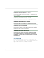
Disclaimers
Copyright © 2003 Netopia, Inc.
All rights reserved, Printed in the USA.
The information in this document is subject to change without notice. The statements, configurations, technical data, and recommendations in this document are believed to be accurate and reliable, but are presented without express or implied warranty. Users
must take full responsibility for the applications of any products specified in this document.
Portions of this software are subject to the Mozilla Public License Version 1.1. Portions created by Netscape are copyright 1994-2000
Netscape Communications Corporation. You may obtain a copy of the license at http://www.mozilla.org/MPL/. Software distributed
under the License is distributed on an “as is” basis, WITHOUT WARRANTY OF ANY KIND, either express or implied. See the License
for the specific language governing rights and limitations under the License.
Portions of this software copyright 1988, 1991 by Carnegie Mellon University. All rights reserved. Permission to use, copy, modify,
and distribute this software and its documentation for any purpose and without fee is hereby granted, provided that the above copyright notice and this permission notice appear in supporting documentation, and that the name of Carnegie Mellon University not
be used in advertising or publicity pertaining to distribution of the software without specific, written prior permission.
CARNEGIE MELLON UNIVERSITY DISCLAIMS ALL WARRANTIES WITH REGARD TO THIS SOFTWARE, INCLUDING ALL IMPLIED WARRANTIES OF MERCHANTABILITY AND FITNESS. IN NO EVENT SHALL CMU BE LIABLE FOR ANY SPECIAL, INDIRECT, OR CONSEQUENTIAL DAMAGES OR ANY DAMAGES WHATSOEVER RESULTING FROM LOSS OF USE, DATA, OR PROFITS, WHETHER IN AN
ACTION OF CONTRACT, NEGLIGENCE, OR OTHER TORTIOUS ACTION, ARISING OUT OF OR IN CONNECTION WITH THE USE OR
PERFORMANCE OF THIS SOFTWARE.
The information in this document is proprietary to Netopia, Inc.
Trademarks
Netopia and Cayman are registered trademarks, and “Making Broadband Work” is a trademark of Netopia, Inc. All rights reserved.
Ethernet is a registered trademark of Xerox Corporation. Microsoft and Windows are registered trademarks of Microsoft Corporation.
All other trademarks are the property of their respective owners. Mention of third-party products is for informational purposes only
and constitutes neither an endorsement nor a recommendation. Netopia assumes no responsibility with regard to the performance
or use of these products.
Statement of Conditions
In the interest of improving internal design, operational function, and /or reliability, Netopia, Inc. reserves the right to make changes
to the products described in this document without notice.
Netopia, Inc. does not assume any liability that may occur due to the use or application of the product(s) or network configurations described herein.
Netopia, Inc. Part Number: 6161139-00-02d4 v011503
2
Table of Contents
Table of Contents
Disclaimers
CHAPTER 1
.........................................2
Introduction . . . . . . . . . . . . . . . . . . . . . . . . . . . . . . . . . . 8
About Cayman Documentation
.........................8
Intended Audience . . . . . . . . . . . . . . . . . . . . . . . . . . . . . . . . . . 10
Documentation Conventions . . . . . . . . . . . . . . . . . . . . . . . . . . 11
General . . . . . . . . . . . . . . . . . . . . . . . . . . . . . . . . . . . . . . . . . . . . . . . . .11
Internal Web Interface . . . . . . . . . . . . . . . . . . . . . . . . . . . . . . . . . . . . . .11
Command Line Interface . . . . . . . . . . . . . . . . . . . . . . . . . . . . . . . . . . . 12
Text . . . . . . . . . . . . . . . . . . . . . . . . . . . . . . . . . . . . . . . . . . . . . . . . . . . 12
Organization . . . . . . . . . . . . . . . . . . . . . . . . . . . . . . . . . . . . . . . 13
Overview of Major Capabilities . . . . . . . . . . . . . . . . . . . . . . . . . 14
CHAPTER 2
Quickstart . . . . . . . . . . . . . . . . . . . . . . . . . . . . . . . . . 15
Important Safety Instructions
. . . . . . . . . . . . . . . . . . . . . . . . . . 16
POWER SUPPLY INSTALLATION . . . . . . . . . . . . . . . . . . . . . . . . . . . 16
TELECOMMUNICATION INSTALLATION. . . . . . . . . . . . . . . . . . . . . . 16
1. Unpack the Cayman Gateway . . . . . . . . . . . . . . . . . . . . . . . 17
2. Set up the Cayman Gateway . . . . . . . . . . . . . . . . . . . . . . . . 18
3. Configure the Cayman 3346
........................
Cayman 3346 Status Indicator Lights
...................
Home Page
.......................................
Bridged Mode Quickstart . . . . . . . . . . . . . . . . . . . . . . . . . . . . .
22
25
26
28
Important Safety Instructions . . . . . . . . . . . . . . . . . . . . . . . . . . . . . . . . 28
1. Unpack the Cayman Gateway . . . . . . . . . . . . . . . . . . . . . . . 29
2. Set up the Cayman Gateway . . . . . . . . . . . . . . . . . . . . . . . . 30
3
Table of Contents
CHAPTER 3
Basic Troubleshooting . . . . . . . . . . . . . . . . . . . . . . . . . . 32
Status Indicator Lights . . . . . . . . . . . . . . . . . . . . . . . . . . . . . . . 33
Factory Reset Switch . . . . . . . . . . . . . . . . . . . . . . . . . . . . . . . . 36
CHAPTER 4
Web-based User Interface . . . . . . . . . . . . . . . . . . . . . . . 37
Overview of Major Capabilities
. . . . . . . . . . . . . . . . . . . . . . . . . 37
Feature Keys . . . . . . . . . . . . . . . . . . . . . . . . . . . . . . . . . . . . . . . . . . . . 38
Wide Area Network Termination . . . . . . . . . . . . . . . . . . . . . . . . . . . . . . 39
PPPoE/PPPoA (Point-to-Point Protocol over Ethernet/ATM) . . . . 39
Instant-On PPP . . . . . . . . . . . . . . . . . . . . . . . . . . . . . . . . . . . . . . . 39
Simplified Local Area Network Setup . . . . . . . . . . . . . . . . . . . . . . . . . . 41
DHCP (Dynamic Host Configuration Protocol) Server . . . . . . . . . 41
DNS Proxy . . . . . . . . . . . . . . . . . . . . . . . . . . . . . . . . . . . . . . . . . . 41
Management . . . . . . . . . . . . . . . . . . . . . . . . . . . . . . . . . . . . . . . . . . . . . 42
Embedded Web Server . . . . . . . . . . . . . . . . . . . . . . . . . . . . . . . . 42
Diagnostics . . . . . . . . . . . . . . . . . . . . . . . . . . . . . . . . . . . . . . . . . . 42
IPMaps . . . . . . . . . . . . . . . . . . . . . . . . . . . . . . . . . . . . . . . . . . . . . . . . . 43
Security . . . . . . . . . . . . . . . . . . . . . . . . . . . . . . . . . . . . . . . . . . . . . . . . . 43
Remote Access Control . . . . . . . . . . . . . . . . . . . . . . . . . . . . . . . . 43
Password Protection . . . . . . . . . . . . . . . . . . . . . . . . . . . . . . . . . . . 43
Network Address Translation (NAT) . . . . . . . . . . . . . . . . . . . . . . . 44
Cayman Advanced Features for NAT . . . . . . . . . . . . . . . . . . . . . . 45
Internal Servers . . . . . . . . . . . . . . . . . . . . . . . . . . . . . . . . . . . . . . 46
Pinholes . . . . . . . . . . . . . . . . . . . . . . . . . . . . . . . . . . . . . . . . . . . . 46
Default Server . . . . . . . . . . . . . . . . . . . . . . . . . . . . . . . . . . . . . . . . 47
Combination NAT Bypass Configuration . . . . . . . . . . . . . . . . . . . 47
VPN IPSec Pass Through . . . . . . . . . . . . . . . . . . . . . . . . . . . . . . 47
Access the Web UI
. . . . . . . . . . . . . . . . . . . . . . . . . . . . . . . . . . 49
Open the Web Connection . . . . . . . . . . . . . . . . . . . . . . . . . . . . . . . . . . 49
Home Page . . . . . . . . . . . . . . . . . . . . . . . . . . . . . . . . . . . . . . . . . . . . . . 50
Home Page - Information . . . . . . . . . . . . . . . . . . . . . . . . . . . . . . . . . . . 51
Toolbar . . . . . . . . . . . . . . . . . . . . . . . . . . . . . . . . . . . . . . . . . . . 52
Navigating the Web Interface . . . . . . . . . . . . . . . . . . . . . . . . . . 53
Restart . . . . . . . . . . . . . . . . . . . . . . . . . . . . . . . . . . . . . . . . . . . 54
Help
. . . . . . . . . . . . . . . . . . . . . . . . . . . . . . . . . . . . . . . . . . . . . 56
Configure . . . . . . . . . . . . . . . . . . . . . . . . . . . . . . . . . . . . . . . . . 57
Quickstart . . . . . . . . . . . . . . . . . . . . . . . . . . . . . . . . . . . . . . . . . . . . . . . 57
How to Use the Quickstart Page . . . . . . . . . . . . . . . . . . . . . . . . . 57
4
Table of Contents
Setup Your Gateway using a PPP Connection . . . . . . . . . . . . . . 57
LAN . . . . . . . . . . . . . . . . . . . . . . . . . . . . . . . . . . . . . . . . . . . . . . . . . . . 59
WAN . . . . . . . . . . . . . . . . . . . . . . . . . . . . . . . . . . . . . . . . . . . . . . . . . . 62
Multiple VCs . . . . . . . . . . . . . . . . . . . . . . . . . . . . . . . . . . . . . . . . . . . . 63
Advanced. . . . . . . . . . . . . . . . . . . . . . . . . . . . . . . . . . . . . . . . . . . . . . . 65
Configure Specific Pinholes . . . . . . . . . . . . . . . . . . . . . . . . . . . . 68
Planning for Your Pinholes . . . . . . . . . . . . . . . . . . . . . . . . . . . . . 68
Example: A LAN Requiring Three Pinholes . . . . . . . . . . . . . . . . 68
Pinhole Configuration Procedure . . . . . . . . . . . . . . . . . . . . . . . . 71
Configure the IPMaps Feature . . . . . . . . . . . . . . . . . . . . . . . . . . . . . . 75
What are IPMaps and how are they used? . . . . . . . . . . . . . . . . . 75
What types of servers are supported by IPMaps? . . . . . . . . . . . 75
Can I use IPMaps with my PPPoE or PPPoA connection? . . . . . 75
Will IPMaps allow IP addresses from different subnets to
be assigned to my Gateway? . . . . . . . . . . . . . . . . . . . . . . . . . . . 75
IPMaps Block Diagram . . . . . . . . . . . . . . . . . . . . . . . . . . . . . . . . 76
Configure a Default Server . . . . . . . . . . . . . . . . . . . . . . . . . . . . . 77
Typical Network Diagram . . . . . . . . . . . . . . . . . . . . . . . . . . . . . . 78
NAT Combination Application . . . . . . . . . . . . . . . . . . . . . . . . . . . 79
Configuring for Bridge Mode . . . . . . . . . . . . . . . . . . . . . . . . . . . . . . . . 84
Security . . . . . . . . . . . . . . . . . . . . . . . . . . . . . . . . . . . . . . . . . . . . . . . . 92
Create and Change Passwords . . . . . . . . . . . . . . . . . . . . . . . . . 92
Install . . . . . . . . . . . . . . . . . . . . . . . . . . . . . . . . . . . . . . . . . . . . . . . . . . 95
Updating Your Gateway’s CaymanOS Version . . . . . . . . . . . . . . 96
Task 1: Required Files . . . . . . . . . . . . . . . . . . . . . . . . . . . . . . . . . . . . . 97
Task 2: CaymanOS Image File . . . . . . . . . . . . . . . . . . . . . . . . . . . . . . 97
Background . . . . . . . . . . . . . . . . . . . . . . . . . . . . . . . . . . . . . . . . . . . . 100
Obtaining Software Feature Keys . . . . . . . . . . . . . . . . . . . . . . . . . . 100
Procedure - Install a New Feature Key File . . . . . . . . . . . . . . . . . . . . 100
CHAPTER 5
Advanced Troubleshooting . . . . . . . . . . . . . . . . . . . . . 104
Home Page . . . . . . . . . . . . . . . . . . . . . . . . . . . . . . . . . . . . . . . . . . . . 105
CHAPTER 6
Command Line Interface . . . . . . . . . . . . . . . . . . . . . . . 118
Overview
. . . . . . . . . . . . . . . . . . . . . . . . . . . . . . . . . . . . . . . . 119
Starting and Ending a CLI Session
. . . . . . . . . . . . . . . . . . . . 122
Logging In . . . . . . . . . . . . . . . . . . . . . . . . . . . . . . . . . . . . . . . . . . . . . 122
Ending a CLI Session . . . . . . . . . . . . . . . . . . . . . . . . . . . . . . . . . . . . 122
Saving Settings . . . . . . . . . . . . . . . . . . . . . . . . . . . . . . . . . . . . . . . . . 123
5
Table of Contents
Using the CLI Help Facility . . . . . . . . . . . . . . . . . . . . . . . . . . . 123
About SHELL Commands . . . . . . . . . . . . . . . . . . . . . . . . . . . . 124
SHELL Prompt . . . . . . . . . . . . . . . . . . . . . . . . . . . . . . . . . . . . . . . . . . 124
SHELL Command Shortcuts. . . . . . . . . . . . . . . . . . . . . . . . . . . . . . . . 124
SHELL Commands
. . . . . . . . . . . . . . . . . . . . . . . . . . . . . . . . . 125
Common Commands . . . . . . . . . . . . . . . . . . . . . . . . . . . . . . . . . . . . . 125
DSL Commands . . . . . . . . . . . . . . . . . . . . . . . . . . . . . . . . . . . . . . . . . 134
About CONFIG Commands
. . . . . . . . . . . . . . . . . . . . . . . . . . 137
CONFIG Mode Prompt . . . . . . . . . . . . . . . . . . . . . . . . . . . . . . . . . . . . 137
Navigating the CONFIG Hierarchy . . . . . . . . . . . . . . . . . . . . . . . . . . . 137
Entering Commands in CONFIG Mode . . . . . . . . . . . . . . . . . . . . . . . 139
Guidelines: CONFIG Commands . . . . . . . . . . . . . . . . . . . . . . . . . . . . 140
Displaying Current Gateway Settings . . . . . . . . . . . . . . . . . . . . . . . . . 141
Step Mode: A CLI Configuration Technique . . . . . . . . . . . . . . . . . . . . 141
Validating Your Configuration . . . . . . . . . . . . . . . . . . . . . . . . . . . . . . . 142
CONFIG Commands
. . . . . . . . . . . . . . . . . . . . . . . . . . . . . . . 143
DSL Commands . . . . . . . . . . . . . . . . . . . . . . . . . . . . . . . . . . . . . . . . . 143
ATM Settings . . . . . . . . . . . . . . . . . . . . . . . . . . . . . . . . . . . . . . . 143
DHCP Settings . . . . . . . . . . . . . . . . . . . . . . . . . . . . . . . . . . . . . . . . . . 145
DMT Settings . . . . . . . . . . . . . . . . . . . . . . . . . . . . . . . . . . . . . . . . . . . 146
Domain Name System Settings . . . . . . . . . . . . . . . . . . . . . . . . . . . . . 146
IP Settings . . . . . . . . . . . . . . . . . . . . . . . . . . . . . . . . . . . . . . . . . . . . . 148
WAN-to-WAN Routing Settings . . . . . . . . . . . . . . . . . . . . . . . . . 154
IP-over-PPP Settings . . . . . . . . . . . . . . . . . . . . . . . . . . . . . . . . . 155
Static ARP Settings . . . . . . . . . . . . . . . . . . . . . . . . . . . . . . . . . . 158
WAN Settings . . . . . . . . . . . . . . . . . . . . . . . . . . . . . . . . . . . . . . . 160
Network Address Translation (NAT) Default Settings . . . . . . . . . . . . . 162
Network Address Translation (NAT) Pinhole Settings. . . . . . . . . . . . . 163
PPPoE Settings . . . . . . . . . . . . . . . . . . . . . . . . . . . . . . . . . . . . . . . . . 164
Configuring Basic PPP Settings . . . . . . . . . . . . . . . . . . . . . . . . . 165
Configuring Port Authentication . . . . . . . . . . . . . . . . . . . . . . . . . 168
Configuring Peer Authentication . . . . . . . . . . . . . . . . . . . . . . . . . 170
Command Line Interface Preference Settings . . . . . . . . . . . . . . . . . . 171
Port Renumbering Settings . . . . . . . . . . . . . . . . . . . . . . . . . . . . . . . . 172
System Settings . . . . . . . . . . . . . . . . . . . . . . . . . . . . . . . . . . . . . . . . . 174
6
Table of Contents
CHAPTER 7
Glossary . . . . . . . . . . . . . . . . . . . . . . . . . . . . . . . . 176
CHAPTER 8
Technical Specifications and Safety Information . . . . . 195
Description
. . . . . . . . . . . . . . . . . . . . . . . . . . . . . . . . . . . . . . . 195
Dimensions: . . . . . . . . . . . . . . . . . . . . . . . . . . . . . . . . . . . . . . . .
Communications interfaces: . . . . . . . . . . . . . . . . . . . . . . . . . . .
Power requirements . . . . . . . . . . . . . . . . . . . . . . . . . . . . . . . . . . . . .
Environment . . . . . . . . . . . . . . . . . . . . . . . . . . . . . . . . . . . . . . . . . . .
Operating temperature: . . . . . . . . . . . . . . . . . . . . . . . . . . . . . . .
Storage temperature: . . . . . . . . . . . . . . . . . . . . . . . . . . . . . . . .
Relative storage humidity: . . . . . . . . . . . . . . . . . . . . . . . . . . . . .
Software and protocols . . . . . . . . . . . . . . . . . . . . . . . . . . . . . . . . . . .
Software media: . . . . . . . . . . . . . . . . . . . . . . . . . . . . . . . . . . . .
Routing: . . . . . . . . . . . . . . . . . . . . . . . . . . . . . . . . . . . . . . . . . . .
WAN support: . . . . . . . . . . . . . . . . . . . . . . . . . . . . . . . . . . . . . .
Security: . . . . . . . . . . . . . . . . . . . . . . . . . . . . . . . . . . . . . . . . . .
Management/configuration methods: . . . . . . . . . . . . . . . . . . . .
Diagnostics: . . . . . . . . . . . . . . . . . . . . . . . . . . . . . . . . . . . . . . . .
Agency approvals
195
195
196
196
196
196
196
196
196
196
196
196
196
196
. . . . . . . . . . . . . . . . . . . . . . . . . . . . . . . . . . 197
Regulatory notices. . . . . . . . . . . . . . . . . . . . . . . . . . . . . . . . . . . . . . . 197
European Community. . . . . . . . . . . . . . . . . . . . . . . . . . . . . . . . . 197
Manufacturer’s Declaration of Conformance
. . . . . . . . . . . . . 198
United States . . . . . . . . . . . . . . . . . . . . . . . . . . . . . . . . . . . . . . . 198
Service requirements . . . . . . . . . . . . . . . . . . . . . . . . . . . . . . . . 199
Canada . . . . . . . . . . . . . . . . . . . . . . . . . . . . . . . . . . . . . . . . . . . 199
Important Safety Instructions . . . . . . . . . . . . . . . . . . . . . . . . . 201
FCC Part 68 Information
. . . . . . . . . . . . . . . . . . . . . . . . . . . . 202
Electrical Safety Advisory . . . . . . . . . . . . . . . . . . . . . . . . . . . . 203
Index . . . . . . . . . . . . . . . . . . . . . . . . . . . . . . . . . . . . . . . . . . . . . 204
7
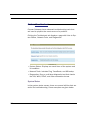
CHAPTER 1
Introduction
About Cayman Documentation
☛
NOTE:
This guide describes the wide variety of features and
functionality of the Cayman 3346, when used in
Router mode. The Cayman 3346 may also be delivered in Bridge mode. In Bridge mode, the Gateway
acts as a pass-through device and allows the workstations on your LAN to have public addresses
directly on the internet.
Netopia, Inc. provides a suite of technical information for its
Cayman-series family of intelligent enterprise and consumer
Gateways. It consists of:
• Software User Guide
8
About Cayman Documentation
• Dedicated Quickstart guides
• Specific White Papers
The documents are available in electronic form as Portable
Document Format (PDF) files. They are viewed (and printed)
from Adobe Acrobat Reader, Exchange, or any other application
that supports PDF files.
They are downloadable from Netopia’s website:
http://www.netopia.com/
9
Intended Audience
This guide is targeted primarily to residential service subscribers.
This guide may also be of use to the support staffs of broadband service providers and advanced residential service subscribers.
10
Documentation Conventions
Documentation Conventions
General
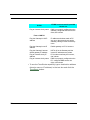
This manual uses the following conventions to present information:
Convention (Typeface)
Description
bold italic
monospaced
Menu commands
bold italic sans serif
Web GUI page links and button names
terminal
Computer display text
bold terminal
User-entered text
Italic
Italic type indicates the complete titles
of manuals.
Internal Web Interface
Convention (Graphics)
dot-dashed rectangle or
line
Description
Denotes an “excerpt” from a Web page
or the visual truncation of a Web page
Denotes an area of emphasis on a Web
page
solid rounded rectangle
with an arrow
11
Command Line Interface
Syntax conventions for the Cayman Gateway command line
interface are as follows:
Convention
Description
straight ([ ]) brackets in cmd
Optional command arguments
line
curly ({ }) brackets, with values Alternative values for an argument are
separated with vertical bars (|). presented in curly ({ }) brackets, with
values separated with vertical bars (|).
User-entered text
bold terminal type
face
italic terminal
type face
Variables for which you supply your
own values
Text
The words “Cayman Gateway” and “Gateway” refer to the Netopia Cayman 3346 Gateway.
The expressions “Release 6.3.0” and “R 6.3.0” refer to the
most recent generally available Cayman Operating System.
12
Organization
Organization
This guide consists of seven chapters, including a glossary, and
an index. It is organized as follows:
• Chapter 1, “Introduction” — Describes the Cayman docu-
•
•
•
•
•
•
•
ment suite, the purpose of, the audience for, and structure
of this guide. It gives a table of conventions and presents a
product description summary.
Chapter 2, “Quickstart” — Describes how to get up and
running with your Cayman 3346.
Chapter 3, “Basic Troubleshooting” — Gives some simple
suggestions for troubleshooting problems with your Gateway’s initial configuration.
Chapter 4, “Web-based User Interface” — Focuses on the
user interface for advanced users. It is organized in the
same way as the Web UI is organized. As you go through
each section, functions and procedures are discussed in
detail.
Chapter 5, “Advanced Troubleshooting” — Gives suggestions and descriptions of expert tools to use to troubleshoot
your Gateway’s configuration.
Chapter 6, “Command Line Interface” — Describes all the
current text-based commands for both the SHELL and CONFIG modes. A summary table and individual command examples for each mode is provided.
Chapter 7, “Glossary”
Index
13
Overview of Major Capabilities
The Netopia 3346 offers simplified setup and management features as well as advanced broadband router capabilities. The
following are some of the main features of the Netopia 3346:
• Wide Area Network Termination
The 3346 combines a traditional modem with an Internet router. It
translates protocols used on the Internet to protocols used by
home personal computers and eliminates the need for special
desktop software (i.e. PPPoE).
• Simplified Local Area Network Setup
Built-in DHCP and DNS proxy features minimize or eliminate the
need to program any network configuration into your home personal computer.
• Management
A Web server built into the Cayman Operating System makes
setup and maintenance easy using standard browsers. Diagnostic
tools facilitate troubleshooting.
• Security
Network Address Translation (NAT), password protection, and
other built-in security features prevent unauthorized remote
access to your network. Pinholes, default server, and other features permit access to computers on your home network that you
can specify.
14
CHAPTER 2
Quickstart
Most users will find that the basic Quickstart configuration is all
that they ever need to use. This section may be all that you ever
need to configure and use your Cayman 3346. The following
instructions cover installation in Router Mode.
This section covers:
• “Important Safety Instructions” on page 16
• “1. Unpack the Cayman Gateway” on page 17
• “2. Set up the Cayman Gateway” on page 18
• “3. Configure the Cayman 3346” on page 22
• “Cayman 3346 Status Indicator Lights” on page 25
• “Home Page” on page 26
If your Cayman 3346 was delivered in Bridged Mode, see
“Bridged Mode Quickstart” on page 28.
15
Important Safety Instructions
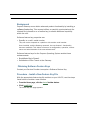
POWER SUPPLY INSTALLATION
Connect the power supply cord to the power jack on the Cayman 3346. Plug the power supply into an appropriate electrical
outlet.
☛
CAUTION:
The Cayman 3346 is designed for use only with a UL
Listed or CSA Certified Class 2 power supply or Limited Power Source, rated 12Vdc, 1A. Do not substitute other non-approved power sources.
TELECOMMUNICATION INSTALLATION
When using your telephone equipment, basic safety precautions should always be followed to reduce the risk of fire, electric shock and injury to persons, including the following:
• Do not use this product near water, for example, near a bath-
tub, wash bowl, kitchen sink or laundry tub, in a wet basement or near a swimming pool.
• Avoid using a telephone (other than a cordless type) during
an electrical storm. There may be a remote risk of electrical
shock from lightning.
• Do not use the telephone to report a gas leak in the vicinity
of the leak.
SAVE THESE INSTRUCTIONS
16
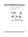
1. Unpack the Cayman Gateway
1. Unpack the Cayman Gateway
4
3
Po
w
er
2
LA
N
D
SL
1
N
LA
N
LA
N
LA
SY
N
C
Verify your package contents.
Cayman Gateway
Power
Supply
Lavender RJ-11
Telephone
Cable
Quickstart
Guide
Yellow RJ-45
Ethernet
Cable
Your package may also include
an optional desk stand and CD
with software and documentation
17
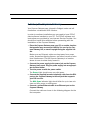
2. Set up the Cayman Gateway
1.
Place the Cayman 3346 near your PC or another location that
permits easy access and visibility.
Make sure any Ethernet cables are kept away from power
cords, fluorescent lighting fixtures, and other sources of electrical interference. Put the Cayman Gateway in a location
where air can circulate freely around it.
2.
3.
Connect the power supply to the power jack on the Cayman
3346 back panel. Plug the power supply into an appropriate
electrical outlet.
Turn the power on with the power switch.
The Power light should come on solid green.
4.
Connect the supplied lavender telephone cable from the DSL
port on the Cayman Gateway to the wall jack that supports
your DSL service.
The DSL SYNC indicator light should blink for up to two minutes and then come on solid green.
5.
Use the yellow Ethernet cable to connect one of the Cayman
Gateway’s Ethernet ports to your PC’s Ethernet port.
A LAN light should come on solid green for the port where
you connected the cable.
18
2. Set up the Cayman Gateway
Ethernet Connection
Ethernet
port
DSL
12v DC
DC Power
4
3
LAN
2
1
Power
Off / On
Power
Switch
DSL
2
3
1
Be sure to enable Dynamic Addressing on your PC. Perform
the following:
19
• Windows 95, 98 and ME.
On your computer, go to:
Open the Network window by double-clicking the Network Icon
In the list of network components,
highlight the entry that says
“TCP/IP ([your Ethernet card here])”.
Click
In the
window,
Select
In the
and click
window, click
and restart your computer.
Proceed to “3. Configure the Cayman 3346” on page 22.
• Windows 2000 and XP
• Right Click on the My Network Places icon on your Windows desktop and select Properties.
• Select your Local Area Connection.
• Right click on your Local Area Connection and select Properties.
20
2. Set up the Cayman Gateway
• Select Internet Protocol [TCP/IP].
• Click the Properties button.
• Click the Obtain IP address automatically radio button and
the Obtain DNS server address automatically radio button.
Click the OK button.
Proceed to “3. Configure the Cayman 3346” on page 22.
• Macintosh Mac OS
Your Macintosh must be using MacOS 7.6.1 or higher.
• Select Control Panels from the Apple Menu.
• Open the TCP/IP Control Panel.
• Choose Connect via Ethernet.
• Choose Configure Using DHCP Server. Close and Save.
Proceed to “3. Configure the Cayman 3346” on page 22.
• Mac OS X
• Launch System Preferences from the Dock or from the
Apple Menu.
• Select the Network Preference Pane.
• Choose Show: Built-in Ethernet.
• Click the TCP/IP tab.
• Choose Configure: Using DHCP.
• Quit System Preferences.
• You do not have to restart the Macintosh. Launch your Web
browser, such as Netscape Navigator or Internet Explorer.
Proceed to “3. Configure the Cayman 3346” on page 22.
21
3. Configure the Cayman 3346
1.
Run your Web browser application, such as Netscape Navigator or Microsoft Internet Explorer, from the computer connected to the Cayman Gateway.
Enter http://192.168.1.254 in the Location text box.
The browser displays the Welcome page.
The browser then displays the Quickstart web page.
2.
22
Enter the username and password supplied by your Internet
Service Provider. Click the Connect to the Internet button.
3. Configure the Cayman 3346
Once you enter your username and password here, you will
no longer need to enter them whenever you access the Internet. The Cayman 3346 stores this information and automatically connects you to the Internet.
The Gateway displays a message while it configures itself.
3.
When the connection succeeds, your browser will display a
success message.
Once a connection is established, your browser is redirected
to your service provider’s home page.
4.
Congratulations! Your installation is complete. You can now
surf to your favorite Web sites by typing an URL in your
browser’s location box or by selecting one of your favorite
Internet bookmarks.
23
☛
Note to Customers with Monitored Alarms or
Emergency Response Systems:
Contact your alarm or emergency response monitoring company and explain that you have installed DSL
service at your business and would like to test your
alarm system. The monitoring company will provide
you with specific instructions to complete this test.
If the alarm fails only when the modem is on, immediately contact BellSouth FastAccess Service at
1-888-321-2DSL (2375), option 2.
24
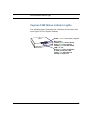
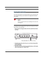
Cayman 3346 Status Indicator Lights
Cayman 3346 Status Indicator Lights
The following figure illustrates the functions of the status indicator lights on the Cayman Gateway.
er
C
4
w
Po
3
N
D
SL
SY
N
N
LA
1
N
N
LA
LA
LA
2
Power - Green when power is applied
DSL SYNC Flashes green when training.
Solid green when trained.
Flashes green for DSL traffic.
LAN 1, 2, 3, 4 Solid green when connected
to each port on the LAN.
Flash green when there is
activity on each port.
25
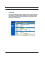
Home Page
After you have performed the basic Quickstart configuration,
any time you log in to your Cayman Gateway you will access the
Cayman 3346 Home Page.
You access the Home Page by typing http://cayman in your Web
browser’s location box.
The Cayman 3346 Home Page appears.
26
Home Page
The Home Page displays the following information in the center
section:
Item
Description
Local WAN IP
Address
This is the negotiated address of the Gateway’s WAN
interface. This address is usually dynamically
assigned.
Remote
Gateway
Address
Primary DNS
Secondary
DNS
ISP Username
Status of
Connection
Serial Number
This is the negotiated address of the remote router to
which this Gateway is connected.
These are the negotiated DNS addresses.
This is your PPPoE username as assigned by your
service provider.
‘Waiting for DSL’ is displayed while the Gateway is
training. This should change to ‘Up’ within two minutes.
‘Up’ is displayed when the ADSL line is synched and
the PPPoE session is established.
This is the unique serial number of your Gateway.
Software
Release
This is the version number of the current embedded
software in your Gateway.
Warranty Date
This is the date that your Gateway was installed and
enabled.
Ethernet Status
Local Area Network (Ethernet) is either Up or
Down
The links in the left-hand column on this page allow you to manage or configure several features of your Gateway. Each link is
described in its own section.
27
Bridged Mode Quickstart
Important Safety Instructions
POWER SUPPLY INSTALLATION
Connect the power supply cord to the power jack on the Cayman Gateway. Plug the power supply into an appropriate electrical outlet.
☛
CAUTION:
The Cayman Gateway is designed for use only with a
UL Listed or CSA Certified Class 2 power supply or
Limited Power Source, rated 12Vdc, 1A. Do not substitute other non-approved power sources.
TELECOMMUNICATION INSTALLATION
When using your telephone equipment, basic safety precautions should always be followed to reduce the risk of fire, electric shock and injury to persons, including the following:
• Do not use this product near water, for example, near a bath-
tub, wash bowl, kitchen sink or laundry tub, in a wet basement or near a swimming pool.
• Avoid using a telephone (other than a cordless type) during
an electrical storm. There may be a remote risk of electrical
shock from lightning.
• Do not use the telephone to report a gas leak in the vicinity
of the leak.
SAVE THESE INSTRUCTIONS
28
1. Unpack the Cayman Gateway
1. Unpack the Cayman Gateway
4
3
Po
w
er
2
LA
N
D
SL
1
N
LA
N
LA
N
LA
SY
N
C
Verify your package contents.
Cayman Gateway
Power
Supply
Lavender RJ-11
Telephone
Cable
Quickstart
Guide
Yellow RJ-45
Ethernet
Cable
Your package may also include
an optional desk stand and CD
with software and documentation
29
2. Set up the Cayman Gateway
Your Cayman Gateway was shipped in Bridged mode and will
function as a traditional ADSL modem.
In order to continue installation you may need to have PPPoE
client software installed on your PC. The PPPoE software and
instructions are provided by your Internet Service Provider. You
should first install this software before proceeding with the
installation of the Cayman Gateway.
1.
Place the Cayman Gateway near your PC or another location
that permits easy access and visibility. You can lay the Cayman Gateway flat, or stand it upright using the supplied cradle.
Make sure any Ethernet cables are kept away from power
cords, fluorescent lighting fixtures, and other sources of electrical interference. Put the Cayman Gateway in a location
where air can circulate freely around it.
2.
3.
Connect the power supply to the power jack on the Cayman
Gateway back panel. Plug the power supply into an appropriate electrical outlet.
Turn the power on with the power switch.
The Power light should come on solid green.
4.
Connect the supplied lavender telephone cable from the DSL
port on the Cayman Gateway to the wall jack that supports
your DSL service.
The DSL Sync indicator light should blink for up to two minutes and then come on solid green.
5.
Connect a yellow Ethernet cable to an Ethernet port on the
Cayman Gateway.
Connect the cable as shown in the following diagram for the
first computer:
30
2. Set up the Cayman Gateway
Ethernet Connection
Ethernet
port
DSL
12v DC
DC Power
4
3
LAN
2
1
Power
Off / On
Power
Switch
DSL
2
3
1
Use the yellow Ethernet cable to connect one of the Cayman
Gateway’s Ethernet ports to your PC’s Ethernet port. The
Ethernet Link light should come on solid green.
6.
Congratulations! Your installation is complete. You can now
surf to your favorite Web sites by typing an URL in your
browser’s location box or by selecting one of your favorite
Internet bookmarks.
31
CHAPTER 3
Basic
Troubleshooting
This section gives some simple suggestions for troubleshooting
problems with your Gateway’s initial configuration.
Before troubleshooting, make sure you have
• read the Quickstart Guide;
• plugged in all the necessary cables; and
• set your PC’s TCP/IP controls to obtain an IP address auto-
matically.
32
Status Indicator Lights
Status Indicator Lights
The first step in troubleshooting is to check the status indicator
lights (LEDs) in the order outlined below.
er
C
4
w
N
Po
D
3
DSL SYNC Flashes green when training.
Solid green when trained.
Flashes green for DSL traffic.
LAN 1, 2, 3, 4 Solid green when connected
to each port on the LAN.
Flash green when there is
activity on each port.
SL
SY
N
N
LA
1
N
N
LA
LA
LA
2
Power - Green when power is applied
LED Function Summary Matrix
Power
DSL SYNC
LAN
1, 2, 3, 4
Unlit
No power
No signal
No signal
Solid
Green
Power on
DSL line synched with the
DSLAM
Synched with
Ethernet card
Flashing
Green
N/A
• Attempting to train with
DSLAM
• Traffic on the DSL link
Activity on the
Ethernet cable
If a status indicator light does not look correct, look for these
possible problems:
33
LED
State
1.
2.
Power
Unlit
3.
4.
1.
2.
DSL
SYNC
Unlit
3.
4.
5.
1.
2.
LAN
1, 2, 3, 4
Unlit
3.
4.
34
Possible problems
Make sure the power switch is in the ON
position.
Make sure the power adapter is plugged
into the Gateway properly.
Try a known good wall outlet.
Replace the power supply and/or unit.
Make sure the you are using the correct
cable. The DSL cable is the thinner standard telephone cable.
Make sure the DSL cable is plugged into
the correct wall jack.
Make sure the DSL cable is plugged into
the DSL port on the Gateway.
Make sure the DSL line has been activated
at the central office DSLAM.
Make sure the Gateway is not plugged into
a micro filter.
Make sure the you are using the Ethernet
cable, not the DSL cable. The Ethernet
cable is thicker than the standard telephone
cable.
Make sure the Ethernet cable is securely
plugged into the Ethernet jack on the PC.
Make sure the Ethernet cable is securely
plugged into the Ethernet port on the Gateway.
Try another Ethernet cable if you have one
available.
Status Indicator Lights
5.
6.
7.
8.
9.
DSL
SYNC
Make sure you have Ethernet drivers
installed on the PC.
Make sure the PC’s TCP/IP Properties for
the Ethernet Network Control Panel is set to
obtain an IP address via DHCP.
Make sure the PC has obtained an address
in the 192.168.1.x range. (You may have
changed the subnet addressing.)
Make sure the PC is configured to access
the Internet over a LAN.
Disable any installed network devices
(Ethernet, HomePNA, wireless) that are not
being used to connect to the Gateway.
Launch a browser and try to browse the Internet. If
Unlit the DSL SYNC light still does not flash, then proceed to “Advanced Troubleshooting” on page 104.
35
Factory Reset Switch
Lose your password? This section shows how to reset the Cayman 3346 so that you can access the configuration screens
once again.
☛
NOTE:
Keep in mind that all of your settings will need to be
reconfigured.
If you don't have a password, the only way to access the Cayman 3346 is the following:
1.
Referring to the diagram below, find the round Reset Switch
opening.
4
3
LAN
2
1
Power
Off / On
DSL
Factory Reset Switch: Push to clear all settings
2.
3.
4.
36
Carefully insert the point of a pen or an unwound paperclip
into the opening.
Press this switch.
This will reset the unit to factory defaults and you will now be
able to reprogram the Cayman 3346.
Overview of Major Capabilities
CHAPTER 4
Web-based User
Interface
Using the Web-based user interface for the Netopia Cayman-series Gateway
you can configure, troubleshoot, and monitor the status of your Gateway.
Overview of Major Capabilities
• “Feature Keys” on page 38
Certain functionality in this release is controlled through software feature keys.
• “Wide Area Network Termination” on page 39
The Gateway combines a traditional modem with an Internet router. It translates
protocols used on the Internet to protocols used by home personal computers
and eliminates the need for special desktop software (i.e. PPPoE).
• “Simplified Local Area Network Setup” on page 41
Built-in DHCP and DNS proxy features minimize or eliminate the need to program any network configuration into your home personal computer.
37
• “Management” on page 42
A Web server built into the Cayman Operating System makes setup and maintenance easy using standard browsers. Diagnostic tools facilitate troubleshooting.
• “IPMaps” on page 43
IPMaps supports one-to-one Network Address Translation (NAT) for IP
addresses assigned to servers, hosts, or specific computers on the LAN side of
the Cayman Gateway.
• “Security” on page 43
Network Address Translation (NAT), password protection, and other built-in
security features prevent unauthorized remote access to your network. Pinholes, default server, and other features permit access to computers on your
home network that you can specify.
Feature Keys
Certain functionality in this release is controlled through software feature
keys. These keys are proprietary files with the following properties:
• They are specific to the serial number of the target unit.
• Once installed, and the Gateway restarted, the desired enhancement is
enabled, which then allows full access to:
•
•
•
•
Configuration
Operation
Maintenance
Administration
• They will not enable the desired feature on a unit with the wrong serial
number.
They are rejected upon “Restart”, not when the file is downloaded.
Enhanced capabilities requiring a feature key include:
• BreakWater Basic Firewall
• SafeHarbour IPSec Tunnel Termination
38
Overview of Major Capabilities
☛
NOTE:
Many Netopia Cayman-series Gateways ship with particular feature key sets pre-enabled. You can check the feature keys
enabled on your Gateway in the System Status web page. See
“System Status” on page 108.
Wide Area Network Termination
PPPoE/PPPoA (Point-to-Point Protocol over Ethernet/ATM). The PPPoE
specification, incorporating the PPP and Ethernet standards, allows your
computer(s) to connect to your Service Provider’s network through your
Ethernet WAN connection. The Cayman-series Gateway supports PPPoE/
PPPoA, eliminating the need to install PPPoE client software on any LAN
computers.
Service Providers may require the use of PPP authentication protocols such
as Challenge Handshake Authentication Protocol (CHAP) or Password
Authentication Protocol (PAP). CHAP and PAP use a username and password
pair to authenticate users with a PPP server.
A CHAP authentication process works as follows:
1.
2.
3.
The password is used to scramble a challenge string.
The password is a shared secret, known by both peers.
The unit sends the scrambled challenge back to the peer.
PAP, a less robust method of authentication, sends a username and password to a PPP server to be authenticated. PAP’s username and password
pair are not encrypted, and therefore, sent “unscrambled”.
Instant-On PPP. You can configure your Gateway for one of two types of
Internet connections:
39
• Always On
• Instant On
These selections provide either a continuous Internet connection or an asneeded connection.
While an Always On connection is convenient, it does leave your network
statically connected to the Internet, and therefore potentially vulnerable to
attacks.
☛
NOTE:
Although the Always On feature may be selected, there are no
guarantees that the connection will never be interrupted.
Cayman's Instant On technology furnishes almost all the benefits of an
Always-On connection while providing two additional security benefits:
• Your network cannot be attacked when it is not connected.
• Your network may change address with each connection making it more
difficult to attack.
When you configure Instant On access, you can also configure an idle timeout value. Your Gateway monitors traffic over the Internet link and when
there has been no traffic for the configured number of seconds, it disconnects the link.
When new traffic that is destined for the Internet arrives at the Gateway, the
Gateway will instantly re-establish the link.
Your service provider may be using a system that assigns the Internet
address of your Gateway out of a pool of many possible Internet addresses.
40
Overview of Major Capabilities
The address assigned varies with each connection attempt, which makes
your network a moving target for any attacker.
Simplified Local Area Network Setup
DHCP (Dynamic Host Configuration Protocol) Server. DHCP Server
functionality enables the Gateway to assign to your LAN computer(s) a “private” IP address and other parameters that allow network communication.
The default DHCP Server configuration of the Gateway supports up to 16
LAN IP addresses.
This feature simplifies network administration because the Gateway maintains a list of IP address assignments. Additional computers can be added
to your LAN without the hassle of configuring an IP address.
DNS Proxy. Domain Name System (DNS) provides end users with the ability to look for devices or web sites by typing their names, rather than IP
addresses. For web surfers, this technology allows your to enter the URL
(Universal Resource Locator) as text to surf to a desired website.
The Cayman DNS Proxy feature allows the LAN-side IP address of the Gateway to be used for proxying DNS requests from hosts on the LAN to the
DNS Servers configured in the gateway. This is accomplished by having the
Gateway's LAN address handed out as the “DNS Server” to the DHCP clients on the LAN.
☛
NOTE:
The Cayman DNS Proxy only proxies UDP DNS queries, not TCP
DNS queries.
41
Management
Embedded Web Server. There is no specialized software to install on your
PC to configure, manage, or maintain your Cayman Gateway. Web pages
embedded in the operating system provide access to the following Gateway
operations:
• Setup
• System and security logs
• Diagnostics functions
Once you have removed your Cayman Gateway from its packing container
and powered the unit up, use any LAN attached PC or workstation running a
common web browser application to configure and monitor the Gateway.
Diagnostics. In addition to the Gateway’s visual LED indicator lights, you
can run an extensive set of diagnostic tools from your Web browser.
Two of the facilities are:
• Automated “Multi-Layer” Test
The Run Diagnostics link initiates a sequence of tests. They examine the
entire functionality of the Gateway, from the physical connections to the data
traffic.
• Network Test Tools
Two test tools to determine network reachability are available:
Ping - tests the “reachability” of a particular network destination by sending an
ICMP echo request and waiting for a reply.
TraceRoute - displays the path to a destination by showing the number of hops
and the router addresses of these hops.
NSLookup - converts a domain name to its IP address and vice versa.
The system log also provides diagnostic information.
42
Overview of Major Capabilities
☛
NOTE:
Your Service Provider may request information that you acquire
from these various diagnostic tools. Individual tests may be performed at the command line. (See “Command Line Interface” on
page 118.).
IPMaps
IPMaps supports one-to-one Network Address Translation (NAT) for IP
addresses assigned to servers, hosts, or specific computers on the LAN
side of the Cayman Gateway.
With IPMaps, a Service Provider-assigned static IP address is mapped to a
specific internal device. This allows a LAN-located device to appear public
without compromising other locally attached devices. The external IP
addresses must be on the same subnet.
IPMaps is used for applications such as Web, email, and FTP servers.
See How To: Configure for IPMaps on page 52 for more information.
Security
Remote Access Control. You can determine whether or not an administrator or other authorized person has access to configuring your Gateway. This
access can be turned on or off in the Web interface.
Password Protection. Access to your Cayman device can be controlled
through two access control accounts, Admin or User.
• The Admin, or administrative user, performs all configuration, manage-
ment or maintenance operations on the Gateway.
43
• The User account provides monitor capability only.
A user may NOT change the configuration, perform upgrades or invoke
maintenance functions.
Network Address Translation (NAT). The Cayman Gateway Network
Address Translation (NAT) security feature lets you conceal the topology of a
hard-wired Ethernet or wireless network connected to its LAN interface from
routers on networks connected to its WAN interface. In other words, the
end computer stations on your LAN are invisible from the Internet.
Only a single WAN IP address is required to provide this security support
for your entire LAN.
LAN sites that communicate through an Internet Service Provider typically
enable NAT, since they usually purchase only one IP address from the ISP.
• When NAT is ON, the Cayman Gateway “proxies” for the end computer
stations on your network by pretending to be the originating host for network communications from non-originating networks. The WAN interface
address is the only IP address exposed.
The Cayman Gateway tracks which local hosts are communicating with which
remote hosts. It routes packets received from remote networks to the correct
computer on the LAN (Ethernet) interface.
• When NAT is OFF, a Cayman Gateway acts as a traditional TCP/IP router,
all LAN computers/devices are exposed to the Internet.
A diagram of a typical NAT-enabled LAN follows:
44
Overview of Major Capabilities
Cayman Gateway
WAN
Ethernet
Interface
Internet
LAN
Ethernet
Interface
NAT
NAT-protected
LAN stations
Embedded Admin Services:
HTTP-Web Server and Telnet Server Port
☛
NOTE:
1. The default setting for NAT is ON.
2. Cayman uses Port Address Translation (PAT) to implement the
NAT facility.
3. NAT Pinhole traffic (discussed below) is always initiated from
the WAN side.
Cayman Advanced Features for NAT. Using the NAT facility provides
effective LAN security. However, there are user applications that require
methods to selectively by-pass this security function for certain types of
Internet traffic.
45
Cayman Gateways provide special pinhole configuration rules that enable
users to establish NAT-protected LAN layouts that still provide flexible bypass capabilities.
Some of these rules require coordination with the unit’s embedded administration services: the internal Web (HTTP) Port (TCP 80) and the internal
Telnet Server Port (TCP 23).
Internal Servers. The internal servers are the embedded Web and Telnet
servers of the Gateway. You would change the internal server ports for Web
and Telnet of the Gateway if you wanted to have these services on the LAN
using pinholes or the Default server. Related to the pinhole configuration
rules is an internal port forwarding facility that enables you to eliminate
conflicts with embedded administrative ports 80 and 23.
Pinholes. This feature allows you to:
• Transparently route selected types of network traffic using the port for-
warding facility.
FTP requests or HTTP (Web) connections are directed to a specific host on your
LAN.
• Setup multiple pinhole paths.
Up to 32 paths are supported
• Identify the type(s) of traffic you want to redirect by port number.
Common TCP/IP protocols and ports are:
FTP (TCP 21)
SMTP (TCP 25)
SNMP (TCP 161, UDP 161)
See page 68 for How To instructions.
46
telnet (TCP 23)
HTTP (TCP 80)
Overview of Major Capabilities
Default Server. This feature allows you to:
• Direct your Gateway to forward all externally initiated IP traffic (TCP and
UDP protocols only) to a default host on the LAN.
• Enable it for certain situations:
Where you cannot anticipate what port number or packet protocol an in-bound
application might use.
For example, some network games select arbitrary port numbers when a connection is opened.
When you want all unsolicited traffic to go to a specific LAN host.
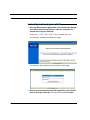
Combination NAT Bypass Configuration. Specific pinholes and Default
Server settings, each directed to different LAN devices, can be used
together.
☛
WARNING:
Creating a pinhole or enabling a Default Server allows inbound
access to the specified LAN station. Contact your Network Administrator for LAN security questions.
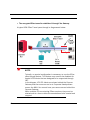
VPN IPSec Pass Through. This Cayman service supports your independent VPN client software in a transparent manner. Cayman has implemented an Application Layer Gateway (ALG) to support multiple PCs running
IP Security protocols.
This feature has three elements:
1.
2.
On power up or reset, the address mapping function (NAT) of the Gateway’s WAN configuration is turned on by default.
When you use your third-party VPN application, the Gateway recognizes
the traffic from your client and your unit. It allows the packets to pass
through the NAT “protection layer” via the encrypted IPSec tunnel.
47
3.
The encrypted IPSec tunnel is established “through” the Gateway.
A typical VPN IPSec Tunnel pass through is diagrammed below:
Cayman
Gateway
☛
NOTE:
Typically, no special configuration is necessary to use the IPSec
pass through feature. This feature may need to be disabled for
special VPN clients that are designed to be supported through
NAT.
In the diagram, VPN PC clients are shown behind the Cayman
Gateway and the secure server is at Corporate Headquarters
across the WAN. You cannot have your secure server behind the
Cayman Gateway.
When multiple PCs are starting IPSec sessions, they must be
started one at a time to allow the associations to be created and
mapped.
48
Access the Web UI
Access the Web UI
Open the Web Connection
Once your Gateway is powered up, you can use any recent version of the
best-known web browsers such as Netscape Navigator or Microsoft Internet
Explorer from any LAN-attached PC or workstation. The procedure is:
1.
2.
Enter the name or IP address of your Cayman Gateway in the Web
browser's window and press Return.
For example, you would enter http://cayman.
If an administrator or user password has been assigned to the Cayman
Gateway, enter Admin or User as the username and the appropriate password and click OK.
The Cayman Gateway Home Page opens.
49
Home Page
The Cayman Gateway Home Page is the expert summary page for your Cayman Gateway. The toolbar at the top provides links to controlling, configuring, and monitoring pages. Critical configuration and operational status is
displayed in the center section.
50
Access the Web UI
Home Page - Information
The Home page’s center section contains a summary of the Gateway’s
configuration settings and operational status.
Summary Information
Field
Status and/or Description
General Information
Hardware
Serial Number
Software Version
Product ID
Model number and summary specification
Unique serial number, located on label attached to bottom of
unit
Release and build number of running Cayman Operating System.
Refers to internal circuit board series; useful in determining
which software upgrade applies to your hardware type.
WAN
Status
Local Address
Connection Type
NAT
Data Rate
(Kbps)
Peer Address
WAN Users
Wide Area Network is either Up or Down
IP address assigned to the WAN port.
May be either Instant On or Always On
On or Off. ON if using Network Address Translation to share
the IP address across many LAN users.
Defines the Downstream (download) and Upstream (upload)
rates that your connection is capable of.
The IP address of the router to which you are connected.
Displays the number of users allotted and the total number
available for use.
LAN
IP Address
Netmask
DHCP Server
Ethernet Status
DHCP Leases
Internal IP address of the Cayman Gateway.
Defines the IP subnet for the LAN
Default is 255.255.255.0 for a Class C device
On or Off. ON if using DHCP to get IP addresses for your LAN
client machines.
Local Area Network (Ethernet) is either Up or Down
A “lease” is held by each LAN client that has obtained an IP
address through DHCP.
51
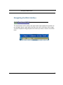
Toolbar
The toolbar is the dark blue bar at the top of the page containing the major
navigation buttons. These buttons are available from almost every page,
allowing you to move freely about the site.
Home
Configure
Quickstart
LAN
WAN
Advanced
52
Troubleshoot
Security
System StaPasswords
tus
Network Tools
Diagnostics
Install
Install Software
Restart
Help
Navigating the Web Interface
Navigating the Web Interface
Link: Breadcrumb Trail
The breadcrumb trail is built in the light brown area beneath the toolbar. As
you navigate down a path within the site, the trail is built from left to right.
To return anywhere along the path from which you came, click on one of the
links.
53
Restart
Button: Restart
The Restart button on the toolbar allows you to restart the Gateway at any
time. You will be prompted to confirm the restart before any action is taken.
The Restart Confirmation message explains the consequences of and reasons for restarting the Gateway
54
Restart
Link: Alert Symbol
The Alert symbol appears in the upper right corner if you make a database
change; one in which a change is made to the Gateway’s configuration. The
Alert serves as a reminder that you must Save the changes and Restart
the Gateway before the change will take effect. You can make many
changes on various pages, and even leave the browser for up to 8 minutes,
but if the Gateway is restarted before the changes are applied, they will be
lost. When you click on the Alert symbol, the Save Changes page appears.
Here you can select various options to save or discard these changes.
If more than one Alert is triggered, you will need to take action to clear the
first Alert before you can see the second Alert.
55
Help
Button: Help
Context-sensitive Help is provided in CaymanOS. The page shown above is
displayed when you are on the Home page or other transitional pages. To
see a context help page example, go to Security -> Passwords, then click
Help.
56
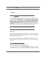
Configure
Configure
Button: Configure
The Configuration options are presented in the order of likelihood you will
need to use them. Quickstart is typically accessed during the hardware
installation and initial configuration phase. Often, these settings should
be changed only in accordance with information from your Service
Provider. LAN and WAN settings are available to fine-tune your system.
Advanced provides some special capabilities typically used for gaming or
small office environments, or where LAN-side servers are involved.
☛
This button will not be available if you log on as User.
Quickstart
How to Use the Quickstart Page. Quickstart is normally used immediately after the new hardware is installed. When you are first configuring your
Gateway, Quickstart appears first.
(Once you have configured your Gateway, logging on displays the Home
page. Thereafter, if you need to use Quickstart, choose it from the Configure menu.)
Link: Configure -> Quickstart
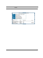
Setup Your Gateway using a PPP Connection.
This example screen is the for a PPP Quickstart configuration. Your gateway authenticates with the Service Provider equipment using the ISP User-
57
name and Password. These values are given to you by your Service
Provider.
1.
2.
Enter your ISP Username and ISP Password.
Click Connect to the Internet.
A brief message is displayed while the Gateway attempts to establish a connection.
3.
When the connection succeeds, your browser will display your Service
Provider’s home page.
If you encounter any problems connecting, refer to the chapters “Basic
Troubleshooting” on page 32 or “Advanced Troubleshooting” on page 104.
58
Configure
LAN
Link: Configure -> LAN
* Interface Enable: Enables all LAN-connected computers to share
resources and to connect to the WAN. The Interface should always be
enabled unless you are instructed to disable it by your Service Provider during troubleshooting.
* IP Address: The LAN IP Address of the Gateway. The IP Address you
assign to your LAN interface must not be used by another device on your
LAN network.
* IP Netmask: Specifies the subnet mask for the TCP/IP network connected to the virtual circuit. The subnet mask specifies which bits of the 32bit binary IP address represent network information. The default subnet
mask for most networks is 255.255.255.0 (Class C subnet mask.)
59
* Restrictions: Specifies whether an administrator can open a Web Administrator or Telnet connection to the Gateway over the LAN interface in order
to monitor and configure the Gateway. On the LAN Interface, you can enable
or disable administrator access. By default, administrative restrictions are
turned off, meaning an administrator can open a Web Administrator or Telnet connection through the LAN Interface.
• Advanced: Clicking on the Advanced link displays the Advanced LAN IP
Interface page.
• RIP Send Mode: Specifies whether the gateway should use Routing Infor-
mation Protocol (RIP) broadcasts to advertise its routing tables to other
routers on your network. You may choose from the following protocols:
• RIP-1: Routing Information Protocol version 1
• RIP-2: RIP Version 2 is an extension of the original Routing Information Protocol (RIP-1) that expands the amount of useful information in the RIP packets.
While RIP-1 and RIP-2 share the same basic algorithms, RIP-2 supports several
new features, including inclusion of subnet masks in RIP packets and implementation of multicasting instead of broadcasting (which reduces the load on
hosts which do not support routing protocols.
• RIP Receive Mode: Specifies whether the Gateway should use Routing
Information Protocol (RIP) broadcasts to update its routing tables with
information received from other routers on your network. The protocol
choices are the same as for the RIP send mode.
60
Configure
• DHCP Server: Your Gateway can provide network configuration information to computers on your LAN, using the Dynamic Host Configuration Protocol (DHCP).
If you already have a DHCP server on your LAN, you should turn this service
off.
If you want the Gateway to provide this service, click the Server Mode pulldown menu, then configure the range of IP addresses that you would like
the Gateway to hand out to your computers.
You can also specify the length of time the computers can use the configuration information; DHCP calls this period the lease time.
Your Service Provider may, for certain services, want to provide configuration from its DHCP servers to the computers on your LANs. In this case, the
Gateway will relay the DHCP requests from your computers to a DHCP
server in the Service Provider's network. Click the relay-agent and enter the
IP address of the Service Provider's DHCP server in the Server Address
field. This address is furnished by the Service Provider.
61
WAN
Link: Configure -> WAN
WAN IP Interfaces
Your IP interfaces are listed. Click on an interface to configure it.
IP Gateway
Enable Gateway: You can configure the Gateway to send packets to a default
gateway if it does not know how to reach the destination host.
Interface Type: If you have PPPoE enabled, you can specify that packets destined for unknown hosts will be sent to the gateway being used by the remote
PPP peer. If you select ip-address, you must enter the IP address of a host on a
local or remote network to receive the traffic.
Default Gateway: The IP Address of the default gateway.
Other WAN Options
62
Configure
PPPoE: You can enable or disable PPPoE. This link also allows configuration of
NAT, admin restrictions, PPPoE username/password, and connection type.
ATM: You can configure the ATM circuits and the number of Sessions. The IP
Interface(s) should be reconfigured after making changes here.
Multiple VCs
Link: Other WAN Options: ATM
With the Tiered Operating System introduced in COS 6.3, Service Providers
may offer their users a choice of 1, 3, or 8 PPPoE sessions as well as up to
8 VPI/VCIs for a single virtual circuit.
This page brings the user to the ATM Circuits page where you can select the
following parameters: VPI, VCI, Encapsulation, and Multiplexing type
To add a VC, click the Click Here link.
63
A second (or subsequent) line of parameters appears, where you can specify alternative values for each VCC.
64
Configure
Advanced
The following are links under Configure -> Advanced:
65
Link: Advanced
Selected Advanced options are discussed in the pages that follow. Many
are self-explanatory or are dictated by your service provider.
Link: IP Static Routes
A static route identifies a manually configured pathway to a remote network.
Unlike dynamic routes, which are acquired and confirmed periodically from
other routers, static routes do not time out. Consequently, static routes are
useful when working with PPP, since an intermittent PPP link may make
maintenance of dynamic routes problematic.
You can configure as many as 16 static IP routes for the Gateway.
Link: IP Static ARP
Your Gateway maintains a dynamic Address Resolution Protocol (ARP) table
to map IP addresses to Ethernet (MAC) addresses. It populates this ARP
table dynamically, by retrieving IP address/MAC address pairs only when it
needs them. Optionally, you can define static ARP entries to map IP
66
Configure
addresses to their corresponding Ethernet MAC addresses. Unlike dynamic
ARP table entries, static ARP table entries do not time out. The IP address
cannot be 0.0.0.0. The Ethernet MAC address entry is in nn-nn-nn-nn-nn-nn
(hexadecimal) format.
Link: Pinholes
Pinholes allow you to transparently route selected types of network traffic,
such as FTP requests or HTTP (Web) connections, to a specific host behind
the Gateway. Creating a pinhole allows access traffic originating from a
remote connection (WAN) to be sent to the internal computer (LAN) that is
specified in the Pinhole page.
Pinholes are common for applications like multiplayer online games. Refer
to software manufacturer application documentation for specific traffic
types and port numbers.
67
Configure Specific Pinholes. Planning for Your Pinholes. Determine if
any of the service applications that you want to provide on your LAN stations use TCP or UDP protocols. If an application does, then you must configure a pinhole to implement port forwarding. This is accessed from the
Advanced -> Pinholes page.
Example: A LAN Requiring Three Pinholes . The procedure on the following pages describes how you set up your NAT-enabled Cayman Gateway
to support three separate applications. This requires passing three kinds of
specific IP traffic through to your LAN.
Application 1: You have a Web server located on your LAN behind your Cayman Gateway and would like users on the Internet to have access to it. With
NAT “On”, the only externally visible IP address on your network is the Gateway’s WAN IP (supplied by your Service Provider). All traffic intended for that
LAN Web server must be directed to that IP address.
Application 2: You want one of your LAN stations to act as the “central
repository” for all email for all of the LAN users.
Application 3: One of your LAN stations is specially configured for game
applications. You want this specific LAN station to be dedicated to games.
A sample table to plan the desired pinholes is:
WAN Traffic Type
Web
Email
Games
Protocol
TCP
TCP
UDP
Pinhole Name
my-webserver
my-mailserver
my-games
LAN Internal IP
Address
192.168.1.1
192.168.1.2
192.168.1.3
For this example, Internet protocols TCP and UDP must be passed through
the NAT security feature and the Gateway’s embedded Web (HTTP) port
must be re-assigned by configuring new settings on the Internal Servers
page.
68
Configure
☛
TIPS for making Pinhole Entries:
1. If the port forwarding feature is required for Web services,
ensure that the embedded Web server’s port number is reassigned PRIOR to any Pinhole data entry.
2. Enter data for one Pinhole at a time.
3. Use a unique name for each Pinhole. If you choose a duplicate
name, it will overwrite the previous information without warning.
69
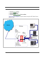
A diagram of this LAN example is:
Gateway
my-webserver
Internet
192.168.1.1
WAN
Ethernet
Interface
210.219.41.20
LAN
Ethernet
Interface
NAT
my-mailserver
192.168.1.2
NAT Pinholes
Embedded
Web Server
210.219.41.20:8100
70
my-games
192.168.1.3
Configure
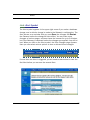
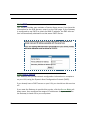
Pinhole Configuration Procedure. Use the following steps:
1.
From the Configure toolbar button -> Advanced link, select the Internal
Servers link.
Since Port Forwarding is required for this example, the Cayman embedded Web
server is configured first.
☛
NOTE:
The two text boxes, Web (HTTP) Server Port and Telnet Sever
Port, on this page refer to the port numbers of the Cayman Gateway’s embedded administration ports.
To pass Web traffic through to your LAN station(s), select a Web (HTTP) Port
number that is greater than 1024. In this example, you choose 8100.
2.
Type 8100 in the Web (HTTP) Server Port text box.
3.
Click the Submit button.
Click Advanced. Select the Pinholes link to go to the Pinhole page.
4.
71
72
5.
Click Add. Type your specific data into the Pinhole Entries table of this
page. Click Submit.
6.
Click on the Pinholes link in the Breadcrumb Trail to go to the Pinholes
entry page. Click Add. Add the next Pinhole. Type the specific data for the
second Pinhole.
Configure
7.
Click on the Pinholes link in the Breadcrumb Trail to go to the Pinholes
entry page. Click the Add. Add the next Pinhole. Type the specific data for
the third Pinhole.
☛
NOTE:
Note the following parameters for the “my-games” Pinhole:
1. The Protocol ID is UDP.
2. The external port is specified as a range.
3. The Internal port is specified as the lower range entry.
8.
Click on the Pinholes link in the Breadcrumb Trail to go to the Pinholes
entry page. Review your entries to be sure they are correct.
Click the Alert button.
10. Select the Save and Restart link to complete the entire Pinhole creation
task and ensure that the parameters are properly saved.
9.
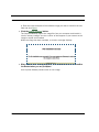
73
☛
NOTE:
REMEMBER: When you have re-assigned the port address for the
embedded Web server, you can still access this facility.
Use the Gateway’s WAN address plus the new port number.
In this example it would be
<WAN Gateway address>:<new port number> or, in this case,
210.219.41.20:8100
Link: IPMaps
IPMaps supports one-to-one Network Address Translation (NAT) for IP
addresses assigned to servers, hosts, or specific computers on the LAN
side of the Cayman Gateway.
A single static or dynamic (DHCP) WAN IP address must be assigned to support other devices on the LAN. These devices utilize Cayman’s default NAT/
PAT capabilities.
74
Configure
Configure the IPMaps Feature
FAQs for the IPMaps Feature
Before configuring an example of an IPMaps-enabled network, review these
frequently asked questions.
What are IPMaps and how are they used? The IPMaps feature allows
multiple static WAN IP addresses to be assigned to the Cayman Gateway.
Static WAN IP addresses are used to support specific services, like a web
server, mail server, or DNS server. This is accomplished by mapping a separate static WAN IP address to a specific internal LAN IP address. All traffic
arriving at the Gateway intended for the static IP address is transferred to
the internal device. All outbound traffic from the internal device appears to
originate from the static IP address.
Locally hosted servers are supported by a public IP address while LAN
users behind the NAT-enabled IP address are protected.
IPMaps is compatible with the use of NAT, with either a statically assigned
IP address or DHCP/PPP served IP address for the NAT table.
What types of servers are supported by IPMaps? IPMaps allows a Cayman Gateway to support servers behind the Gateway, for example, web,
mail, FTP, or DNS servers. VPN servers are not supported at this time.
Can I use IPMaps with my PPPoE or PPPoA connection? Yes. IPMaps
can be assigned to the WAN interface provided they are on the same
subnet. Service providers will need to ensure proper routing to all IP
addresses assigned to your WAN interface.
Will IPMaps allow IP addresses from different subnets to be assigned
to my Gateway? IPMap will support statically assigned WAN IP addresses
from the same subnet.
75
WAN IP addresses from different subnets are not supported.
IPMaps Block Diagram. The following diagram shows the IPMaps principle
in conjunction with existing Cayman NAT operations:
Cayman Gateway
Static IP Addresses
for IPMaps Applications
WAN Interface
LAN Interface
192.168.1.1
NAT/PAT Table
143.137.50.37
143.137.50.36
143.137.50.37
192.168.1.1
143.137.50.36
192.168.1.2
192.168.1.2
143.137.50.35
...
192.168.1.3
...
143.137.50.35
Static IP Addresses
or
DHCP/PPP Served IP Address
for Cayman’s default NAT/PAT
Capabilities
192.168.1.n
LAN stations with WAN IP traffic
forwarded by Cayman’s IPMaps
LAN stations with WAN IP traffic
forwarded by Cayman’s NAT function.
IPMaps:
One-to-One
Multiple Address Mapping
76
192.168.1.3
..
.
192.168.1.n
Configure
Link: Default Server
This feature allows you to:
• Direct your Gateway to forward all externally initiated IP traffic (TCP and
UDP protocols only) to a default host on the LAN.
• Enable it for certain situations:
– Where you cannot anticipate what port number or packet protocol an inbound application might use. For example, some network games select arbitrary port numbers when a connection is opened.
– When you want all unsolicited traffic to go to a specific LAN host.
Configure a Default Server. This feature allows you to direct unsolicited
or non-specific traffic to a designated LAN station. With NAT “On” in the
Gateway, these packets normally would be discarded.
For instance, this could be application traffic where you don’t know (in
advance) the port or protocol that will be used. Some game applications fit
this profile.
Use the following steps to setup a NAT default server to receive this information:
1.
2.
3.
Select the Configure toolbar button, then Advanced, then the Default
Server link.
Check the Enable Default Server checkbox. The NAT Server IP Address
field appears.
Determine the IP address of the LAN computer you have chosen to
receive the unexpected or unknown traffic.
Enter this address in the NAT Server IP Address field.
77
4.
5.
6.
Click the Submit button.
Click the Alert button.
Click the Save and Restart link to confirm.
Typical Network Diagram. A typical network using the NAT Default Server
looks like this:
Internet
Gateway
LAN STN #3
192.168.1.3
WAN
Ethernet
Interface
210.219.41.20
LAN
Ethernet
Interface
NAT
LAN STN #2
192.168.1.2
NAT protected
Embedded
Web Server
210.219.41.20
(Port 80 default)
78
NAT Pinhole
NAT Default Server
192.168.1.1
Configure
NAT Combination Application. Cayman’s NAT security feature allows you
to configure a sophisticated LAN layout that uses both the Pinhole and
Default Server capabilities.
With this topology, you configure the embedded administration ports as a
first task, followed by the Pinholes and, finally, the NAT Default Server.
When using both NAT pinholes and NAT Default Server the Gateway works
with the following rules (in sequence) to forward traffic from the Internet to
the LAN:
1.
2.
3.
If the packet is a response to an existing connection created by outbound
traffic from a LAN PC, forward to that station.
If not, check for a match with a pinhole configuration and, if one is found,
forward the packet according to the pinhole rule.
If there’s no pinhole, the packet is forwarded to the Default Server.
79
Link: DNS
Your Service Provider may maintain a Domain Name server. If you have the
information for the DNS servers, enter it on the DNS page. If your Gateway
is configured to use DHCP to obtain its WAN IP address, the DNS information is automatically obtained from that same DHCP Server.
Link: DHCP Server
Your Gateway can provide network configuration information to computers
on your LAN, using the Dynamic Host Configuration Protocol (DHCP).
If you already have a DHCP server on your LAN, you should turn this service
off.
If you want the Gateway to provide this service, click the Server Mode pulldown menu, then configure the range of IP addresses that you would like
the Gateway to hand out to your computers.
80
Configure
You can also specify the length of time the computers can use the configuration information; DHCP calls this period the lease time.
Your Service Provider may, for certain services, want to provide configuration from its DHCP servers to the computers on your LANs. In this case, the
Gateway will relay the DHCP requests from your computers to a DHCP
server in the Service Provider's network.
Click the relay-agent and enter the IP address of the Service Provider's
DHCP server in the Server Address field. This address is furnished by the
Service Provider.
Link: SNMP
The Simple Network Management Protocol (SNMP) lets a network administrator monitor problems on a network by retrieving settings on remote network devices. The network administrator typically runs an SNMP
management station program on a local host to obtain information from an
SNMP agent. In this case, the Cayman Gateway is an SNMP agent.
You enter SNMP configuration information on this page.
81
Your network administrator furnishes the SNMP parameters.
☛
WARNING:
SNMP presents you with a security issue. The community facility of SNMP behaves somewhat like a password. The community “public” is a well-known community name. It could be used
to examine the configuration of your Gateway by your service
provider or an uninvited reviewer. While Cayman's SNMP implementation does not allow changes to the configuration, the
information can be read from the Gateway.
If you are strongly concerned about security, you may delete
the “public” community.
82
Configure
Link: Advanced -> Ethernet Bridge
The Cayman Gateway can be used as a bridge, rather than a router. A
bridge is a device that joins two networks. As an Internet access device, a
bridge connects the home computer directly to the service provider’s network equipment with no intervening routing functionality, such as Network
Address Translation. Your home computer becomes just another address
on the service provider’s network. In a DSL connection, the bridge serves
simply to convey the digital data information back and forth over your telephone lines in a form that keeps it separate from your voice telephone signals.
If your service provider’s network is set up to provide your Internet connectivity via bridge mode, you can set your Cayman Gateway to be compatible.
Bridges let you join two networks, so that they appear to be part of the
same physical network. As a bridge for protocols other than TCP/IP, your
Gateway keeps track of as many as 255 MAC (Media Access Control)
addresses, each of which uniquely identifies an individual host on a network. Your Gateway uses this bridging table to identify which hosts are
accessible through which of its network interfaces. The bridging table contains the MAC address of each packet it sees, along with the interface over
which it received the packet. Over time, the Gateway learns which hosts are
available through its WAN port and/or its LAN port.
When configured in Bridge Mode, the Cayman will act as a pass-through
device and allow the workstations on your LAN to have public addresses
directly on the internet.
☛
NOTE:
In this mode the Cayman is providing NO firewall protection as is
afforded by NAT. Also, only the workstations that have a public
address can access the internet. This can be useful when you
need to use all five of your static public IP's on the LAN.
83
Configuring for Bridge Mode
1.
2.
3.
4.
84
Browse into the Cayman Gateway’s web interface.
Click on the Configure button in the upper Menu bar.
Click on the LAN link.
The LAN page appears.
In the box titled LAN IP Interface (Ethernet 100BT):
Configure
5.
6.
7.
8.
a. Check the Enable Interface selection.
*Make note of the Ethernet IP Address and subnet mask.
You can use this address to access the router in the future. b. Click Submit.
Click on DHCP Server in the box titled Other LAN Options:
a. Set Server Mode to Off.
b. Click Submit.
Click on the Advanced link in the left-hand links toolbar.
Under the heading of Services, click on the Ethernet Bridge link.
The Ethernet Bridge page appears.
Check the Enable Bridging Function selection.
The window expands.
85
Under Ethernet 100BT (LAN):
Check the Enable Bridging on Port selection.
10. Under RFC-1483 Bridged Ethernet vcc1 (WAN), or under PPP over Ethernet vcc1 (WAN) [as per your configuration]:
a. Check the Enable Bridging on Port selection.
b. Click Submit.
11. Click on the Configure link in the Breadcrumb Trail directly above the
selection box.
9.
Click on the WAN link that takes you to the WAN IP Interfaces box.
13. Click on RFC-1483 Bridged Ethernet vcc1, or on PPP over Ethernet vcc1
[as per your configuration]:
a. Uncheck the Enable Interface selection.
b. Click Submit.
12.
86
Configure
14.
Click on the WAN link in the Breadcrumb Trail directly above the selection
box.
In the box labeled IP Gateway:
a. Uncheck the Enable Gateway Option selection.
b. Click Submit.
16. Click on the Configure link in the Breadcrumb Trail directly above the
selection box.
17. At this point you should be ready to do the final save on the configuration
changes you have made.
15.
The yellow Alert symbol will show up underneath the Help button on the righthand end on the menu bar.
18. Click on this symbol and you will see whether your changes have been
verified.
87
19.
If you are satisfied with the changes you have made, click Save and
Restart in the Save Database box to Apply changes and restart Gateway.
You have now configured your Cayman Gateway for bridging, and it will
bridge all traffic across the WAN. You will need to make configurations to
your machines on your LAN. These settings must be made in accordance
with your ISP. If you ever need to get back into the Cayman Gateway again
for management reasons, you will need to manually configure your machine
to be in the same subnet as the Ethernet interface of the Cayman.
88
Configure
Link: System
The System Name defaults to your Gateway's factory identifier combined
with its serial number. Some cable-oriented Service Providers use the System Name as an important identification and support parameter. If your
Gateway is part of this type of network, do NOT alter the System Name
unless specifically instructed by your Service Provider.
The System Name can be 1-63 characters long; it can include embedded
spaces and special characters.
The Log Message Level alters the severity at which messages are collected in the Gateway's system log. Do not alter this field unless instructed
by your Support representative.
89
Link: Internal Servers
Your Gateway ships with an embedded Web server and support for a Telnet
session, to allow ease of use for configuration and maintenance. The
default ports of 80 for HTTP and 23 for Telnet may be reassigned. This is
necessary if a pinhole is created to support applications using port 80 or
23. See See “Pinholes” on page 67. for more information on Pinhole configuration.
Web (HTTP) Server Port: To reassign the port number used to access the
Cayman embedded Web server, change this value to a value greater than
1024. When you next access the embedded Cayman Web server, append
the IP address with <port number>, (e.g. Point your browser to http://
210.219.41.20:8080).
Telnet Server Port: To reassign the port number used to access your Cayman embedded Telnet server, change this value to a value greater than
1024. When you next access the Cayman embedded Telnet server, append
the IP address with <port number>, (e.g. telnet 210.219.41.20 2323).
90
Configure
Link: Clear Options
To restore the factory configuration of the Gateway, choose Clear Options.
You may want to upload your configuration to a file before performing this
function.
Clear Options does not affect the software image or BootPROM.
You must restart the Gateway for Clear Options to take effect.
91
Security
Button: Security
The Security features are available by clicking on the Security toolbar button. Some items of this category do not appear when you log on as User.
Link: Passwords
Access to your Gateway may be controlled through two optional user
accounts, Admin and User. When you first power up your Gateway, you create a password for the Admin account. The User account does not exist by
default. As the Admin, a password for the User account can be entered or
existing passwords changed.
Create and Change Passwords. You can establish different levels of
access security to protect your Cayman Gateway settings from unauthorized
display or modification.
92
Configure
• Admin level privileges let you display and modify all settings in the Cay-
man Gateway (Read/Write mode). The Admin level password is created
when you first access your Gateway.
• User level privileges let you display (but not change) settings of the Cayman Gateway. (Read Only mode)
To prevent anyone from observing the password you enter, characters in the
old and new password fields are not displayed as you type them.
To display the Passwords window, click the Security toolbar button on the
Home page.
Use the following procedure to change existing passwords or add the User
password for your Cayman Gateway:
93
1.
2.
3.
Select the password type from the Password Level pull-down list.
Choose from Admin or User.
If you assigned a password to the Cayman Gateway previously, enter
your current password in the Old Password field.
Enter your new password in the New Password field.
Cayman’s rules for a Password are:
• It can have up to eight alphanumeric characters.
• It is case-sensitive.
4. Enter your new password again in the Confirm Password field.
You confirm the new password to verify that you entered it correctly the first
time.
5. When you are finished, click the Submit button to store your modified
configuration in the Cayman unit’s memory.
Password changes are automatically saved, and take effect immediately.
94
Configure
Install
Button: Install
From the Install toolbar button you can Install new Operating System Software as updates become available.
95
Link: Install Software
This page allows you to install an updated release of the Cayman Operating
System (CaymanOS).
Updating Your Gateway’s CaymanOS Version. You install a new operating system image in your unit from the Install Operating System Software
page. For this process, the computer you are using to connect to the Cayman Gateway must be on the same local area network as the Cayman Gateway.
Required Tasks
• “Task 1: Required Files” on page 97
• “Task 2: CaymanOS Image File” on page 97
96
Configure
Task 1: Required Files
Upgrading the CaymanOS requires a Cayman Operating System image file.
Background
When you downloaded your operating system upgrade from the Netopia
website you downloaded a ZIP file containing these files:
• Software Upgrade Instructions PDF file
• Cayman Operating System image for your Gateway
Confirm CaymanOS Image Files
The CaymanOS Image file is specific to the model and the product identification (PID) number.
1.
2.
Confirm that you have received the appropriate CaymanOS Image file.
Save the CaymanOS image file to a convenient location on your PC.
Task 2: CaymanOS Image File
Install the CaymanOS Image
To install the CaymanOS software in your Cayman Gateway from the Home
Page use the following steps:
1.
2.
3.
Open a web connection to your Cayman Gateway from the computer on
your LAN.
Click the Install Software button on the Cayman Gateway Home page.
The Install New Cayman Software window opens.
Enter the filename into the text box by using one of these techniques:
The CaymanOS file name starts with the letter “c” (for “CaymanOS”).
a. Click the Browse button, select the file you want, and click Open.
-or-
97
4.
5.
98
b. Enter the name and path of the software image you want to install in the text
field and click Open.
Click the Install Software button.
The Cayman Gateway copies the image file from your computer and installs it
into its memory storage. You see a series of dots appear on your screen as the
image is copied and installed.
When the image has been installed, a success message displays.
When the success message appears, click the Restart button and confirm
the Restart when you are prompted.
Your Cayman Gateway restarts with its new image.
Configure
Verify the CaymanOS Release
To verify that the CaymanOS image has loaded successfully, use the following steps:
1.
2.
Open a web connection to your Cayman Gateway from the computer on
your LAN and return to the Home page.
Verify your CaymanOS Software Release, as shown on the Home Page.
This completes the upgrade process.
Link: Install Keys
You can obtain advanced product functionality by employing a software Feature Key. Software feature keys are specific to a Gateway's serial number.
Once the feature key file is installed and the Gateway is restarted, the new
feature's functionality becomes enabled.
99
Background
Cayman Gateway users obtain advanced product functionality by installing a
software feature key. This concept utilizes a specially constructed and distributed file (referred to as a feature key) to enable additional capability
within the unit.
Software feature key properties are:
• Specific to a unit’s serial number
They will not be accepted on a platform with another serial number.
Once installed, and the Gateway restarted, the new feature’s functionality
becomes available. This allows full access to configuration, operation, maintenance and administration of the new enhancement.
Software feature keys for the Cayman Operating System enable these
enhancements:
• BreakWater Basic Firewall
• SafeHarbour IPSec Tunnel at the Gateway
Obtaining Software Feature Keys
Contact your Service Provider to acquire a Software Feature Key.
Procedure - Install a New Feature Key File
With the appropriate feature key file resident on your LAN PC, use the steps
listed below to enable a new function.
1.
2.
100
From the Home page, click the Install toolbar button.
Click Install Keys
The Install Key File page appears.
Configure
3.
4.
5.
Enter the feature key file name in the input Text Box.
Browse your drive for the file, or
Type the full path and file name in the Text Box.
Click the Install Keys button.
Click the Restart toolbar button.
The Confirmation screen appears.
101
6.
Click the Restart the Gateway link to confirm.
To check your installed features:
1.
2.
102
Click the Install toolbar button.
Click the List of Features link.
The System Status page appears with the information from the features link
displayed below. You can check that the feature you just installed is enabled.
Configure
103
CHAPTER 5
Advanced
Troubleshooting
Advanced Troubleshooting can be accessed from the Gateway’s
Web UI. Point your browser to http://cayman. The main page displays the device status. (If this does not make the Web UI
appear, then do a release and renew in Windows networking to
see what the Gateway address really is.)
104
Home Page
The home page displays basic information about the Gateway.
This includes the ISP Username, Connection Status, Device
Address, Device Address Gateway, DNS-1, and DNS-2. If you
are not able to connect to the Internet, verify the following:
Item
Description
Local WAN IP
Address
This is the negotiated address of the Gateway’s WAN
interface. This address is usually dynamically
assigned.
Remote
Gateway
Address
This is the negotiated address of the remote router to
which this Gateway is connected.
105
Item
Description
‘Waiting for DSL’ is displayed while the Gateway is
training. This should change to ‘Up’ within two minutes.
If not, make sure an RJ-11 cable is used, the Gateway
is connected to the correct wall jack, and the Gateway
is not plugged into a micro filter.
Status of
Connection
‘No Connection’ is displayed if the Gateway has
trained but failed the PPPoE login. This usually means
an invalid user name or password. Go to Configure
and change the PPPoE name and password.
‘Up’ is displayed when the ADSL line is synched and
the PPPoE session is established.
106
ISP Username
This should be the valid PPPoE username. If not, go to
Configure and change to the correct username.
Device
Address
This is the negotiated address of the Gateway’s WAN
interface.
This address is often dynamically assigned. Make
sure this is a valid address.
If this is not the correct assigned address, go to Configure and verify the PPPoE address has not been
manually assigned.
Device
Gateway
This is the negotiated address of the remote router.
Make sure this is a valid address.
If this is not the correct address, go to Configure and
verify the address has not been manually assigned.
Primary DNS
Secondary
DNS
These are the negotiated DNS addresses. Make sure
they are valid DNS addresses.
If these are not the correct addresses, go to Configure
and verify the addresses have not been manually
assigned.
Serial
Number
This is the unique serial number of your Gateway.
Ethernet
Status
This is the status of your Ethernet connection. It
should be Up.
Item
Description
Software
Release
This is the version number of the current embedded
software in your Gateway.
Warranty Date
This is the date that your Gateway was installed and
enabled.
107
Button: Troubleshoot
Cayman Gateways have advanced troubleshooting tools that
are used to pinpoint the exact source of a problem.
Clicking the Troubleshoot tab displays a page with links to System Status, Network Tools, and Diagnostics.
• System Status: Displays an overall view of the system and
its condition.
• Network Tools: Includes Ping, TraceRoute, and NSLookup.
• Diagnostics: Runs a multi-layer diagnostic test that checks
the LAN, WAN, PPPoE, and other connection issues.
System Status
In the system status screen, there are several utilities that are
useful for troubleshooting. Some examples are given below.
108
Link: Ports: Ethernet
The Ethernet port selection shows the traffic sent and received
on the Ethernet interface. There should be frames and bytes on
both the upstream and downstream sides. If there are not, this
could indicate a bad Ethernet cable or no Ethernet connection.
Below is an example:
Ethernet Driver Statistics - Device Number 0
Ethernet Receiver ( Upstream )
Total good frames
0
Total bytes received
0
Total errors
0
Total UCast frames
0
Total MCast frames
0
Total discard frames
0
Ethernet Transmitter ( Downstream )
Total bytes sent
Total errors
612
0
Total UCast frames
14
Total MCast frames
0
Total discard frames
0
109
Link: Ports: DSL
The DSL port selection shows the state of the DSL line,
whether it is up or down and how many times the Gateway
attempted to train. The state should indicate ‘up’ for a working
configuration. If it is not, check the DSL cable and make sure it
is plugged in correctly and not connected to a micro filter. Below
is an example:
ADSL Line State:
Up
ADSL Startup Attempts:
5
SNR Margin:
Line Attenuation:
Errored Seconds:
Upstream
----------
----------
18.6
14.0 dB
0.4
4.0 dB
14
3
Loss of Signal:
4
4
Loss of Frame:
0
0
CRC Errors:
0
0
8000
800
Data Rate:
110
Downstream
Link: DSL: Circuit Configuration
The DSL Circuit Configuration screen shows the traffic sent and
received over the DSL line as well as the trained rate (upstream
and downstream) and the VPI/VCI. Verify traffic is being sent
over the DSL line. If not, check the cabling and make sure the
Gateway is not connected to a micro filter. Also verify the correct PVC is listed, which should be 8/35 (some providers use
other values, such as 0/35. Check with your provider). If not go
to the WAN setup and change the VPI/VCI to its correct value.
Below is an example:
ATM port status
: Up
Rx data rate (bps) : 8000
Tx data rate (bps) : 800
ATM Virtual Circuits:
VCC #
Type
VPI
VCI
----
----
---
-----
1
PVC
8
35
Encapsulation
-------------------------PPP over Ethernet (LLC/SNAP encapsulation)
ATM Circuit Statistics:
Rx Frames
:
17092
Tx Frames
:
25078
Rx Octets
:
905876
Tx Octets
:
1329134
Rx Errors
:
0
Tx Errors
:
0
Rx Discards
:
0
Tx Discards
:
0
No Rx Buffers :
0
Tx Queue Full :
0
111
Link: System Log: Entire
The system log shows the state of the WAN connection as well
as the PPPoE session. Verify that the PPPoE session has been
correctly established and there are no failures. If there are
error messages, go to the WAN configuration and verify the settings. The following is an example of a successful connection:
3/30/2002 19:22:58> ADSL detected
3/30/2002 19:23:4> ATM Connected
3/30/2002 19:23:4> ATM layer is up, cell delineation achieved
3/30/2002 19:23:4> ADSL connected
3/30/2002 19:23:8> PPP1 PPPoE Session is established.
3/30/2002 19:23:8> PPP PAP Authentication success
3/30/2002 19:23:8> PPP1: PPP IP address is 163.176.224.71
3/30/2002 19:23:8> PPP1: PPP Gateway IP address is 163.176.224.254
3/30/2002 19:23:8> PPP1: DNS Primary IP address is 163.176.4.10
3/30/2002 19:23:8> PPP1: DNS Secondary IP address is 163.176.4.32
3/30/2002 19:23:8> NAT/NAPT Session Start: VC# 0, WAN IP is 163.176.224.71
3/30/2002 19:23:8> NAPT: sesPVC0 session is up.
3/30/2002 19:23:9> PPP1 Session is up.
112
Diagnostics
The diagnostics section tests a number of different things at
the same time, including the DSL line, the Ethernet interface
and the PPPoE session.
Possible results are as follows:
CODE
PASS
FAIL
Description
The test was successful.
The test was unsuccessful.
113
CODE
SKIPPED
PENDING
WARNING
Description
The test was skipped because a test on which it
depended failed, or it was not supported by the service
provider equipment to which it is connected.
The test timed out without producing a result. Try running the test again.
The test was unsuccessful. The Service Provider equipment your Gateway connects to may not support this
test.
Network Tools
Three test tools are available from this page.
• NSLookup - converts a domain name to its IP address and
vice versa.
• Ping - tests the “reachability” of a particular network destination by sending an ICMP echo request and waiting for a
reply.
• TraceRoute - displays the path to a destination by showing
the number of hops and the router addresses of these hops.
114
PING: The network tools section sends a PING from the Gateway to either the LAN or WAN to verify connectivity. A PING could
be either an IP address (163.176.4.32) or Domain Name
(www.netopia.com).
• To use the Ping capability, type a destination address
(domain name or IP address) in the text box and click the
Ping button.
Example: Ping to grosso.com.
Result: The host was reachable with four out of five packets
sent.
Below are some specific tests:
Action
If PING is not successful, possible
causes are:
From the Gateway's
Network Tools page:
Ping the internet default gateway IP address
DSL is down, DSL or ATM settings are
incorrect; Gateway’s IP address or
subnet mask are wrong; gateway
router is down.
Ping an internet site by IP
address
Gateway’s default gateway is incorrect, Gateway’s subnet mask is
incorrect, site is down.
115
Action
Ping an internet site by name
If PING is not successful, possible
causes are:
DNS is not properly configured on the
Gateway; configured DNS servers are
down; site is down.
From a LAN PC:
Ping the Gateway’s LAN IP
address
IP address and subnet mask of PC
are not on the same scheme as the
Gateway; cabling or other connectivity
issue.
Ping the Gateway’s wan IP
address
Default gateway on PC is incorrect.
Ping the Gateway’s internet
default gateway IP address
NAT is off on the Gateway and the
internal IP addresses are private.
Ping an internet site by IP
address
PC's subnet mask may be incorrect,
site is down.
Ping an internet site by name
DNS is not properly configured on the
PC, configured DNS servers are
down, site is down.
• To use the TraceRoute capability, type a destination address
(domain name or IP address) in the text box and click the
TraceRoute button.
116
Example: Show the path to the grosso.com site.
Result: It took 20 hops to get to the grosso.com web site.
• To use the NSLookup capability, type an address (domain
name or IP address) in the text box and click the NSLookup
button.
Example: Show the IP Address for grosso.com.
Result: The DNS Server doing the lookup is displayed in the
Server: and Address: fields. If the Name Server can find
your entry in its table, it is displayed in the Name: and
Address: fields.
117
CHAPTER 6
Command Line
Interface
The Cayman Gateway operating software includes a command
line interface (CLI) that lets you access your Cayman Gateway
over a telnet connection. You can use the command line interface to enter and update the unit’s configuration settings, monitor its performance, and restart it.
This chapter covers the following topics:
• “Overview” on page 119
• “Starting and Ending a CLI Session” on page 122
• “Using the CLI Help Facility” on page 123
• “About SHELL Commands” on page 124
• “SHELL Commands” on page 125
• “About CONFIG Commands” on page 137
• “CONFIG Commands” on page 143
118
Overview
Overview
The CLI has two major command modes: SHELL and CONFIG.
Summary tables that list the commands are provided below.
Details of the entire command set follow in this section.
SHELL Commands
Command
arp
atmping
clear
configure
diagnose
download
help
install
log
loglevel
netstat
nslookup
ping
quit
reset
restart
show
start
status
telnet
upload
who
Status and/or Description
send ARP request
send ATM OAM loopback (DSL only)
erase all stored configuration information
set the unit’s options
run the automatic self-test
download the config file
get more information on a command: “help all” or “help
help”
download and program an image into flash
add a message to the diagnostic log
report or change diagnostic log level
show IP information
send DNS query for host
send ICMP echo request
quit this shell
reset subsystems
restart the Gateway
display specific system information
start subsystem
display basic status of Gateway
telnet to a remote host
upload config file
show who is using the shell
119
CONFIG Commands
Command
Verbs
set
define
delete
view
script
help
save
Status and/or Description
Set configuration data
Define environment data
Delete configuration list data
View configuration data
Print configuration data
Help command option
Save configuration data
Keywords
system
pppoe
dmt
atm
bncp
ip
dhcp
nat-default
dns
bridge
ppp
pinhole
security
servers
validate
preference
Gateway’s system options
PPP over Ethernet options
DMT ADSL options
ATM options (DSL only)
Bridge CP options
TCP/IP protocol options
Dynamic Host Configuration Protocol options
Network Address Translation default options
Domain Name System options
Bridge options
Peer-to-Peer Protocol options
Pinhole options
Security options
Internal Server options
Validate configuration settings
Shell environment settings
Command
Utilities
120
Overview
top
quit
exit
Go to top level of configuration mode
Exit from configuration mode; return to shell mode
Exit from configuration mode; return to shell mode
121
Starting and Ending a CLI Session
Open a telnet connection from a workstation on your network.
You initiate a telnet connection by issuing the following command from an IP host that supports telnet, for example, a personal computer running a telnet application such as NCSA
Telnet.
telnet <ip_address>
You must know the IP address of the Cayman Gateway before
you can make a telnet connection to it. By default, your Cayman
Gateway uses 192.168.1.254 as the IP address for its LAN
interface. You can use a Web browser to configure the Cayman
Gateway IP address.
Logging In
The command line interface log-in process emulates the log-in
process for a UNIX host. To logon, enter the username (either
admin or user), and your password.
• Entering the administrator password lets you display and
update all Cayman Gateway settings.
• Entering a user password lets you display (but not update)
Cayman Gateway settings.
When you have logged in successfully, the command line interface lists the username and the security level associated with
the password you entered in the diagnostic log.
Ending a CLI Session
You end a command line interface session by typing quit from
the SHELL node of the command line interface hierarchy.
122
Using the CLI Help Facility
Saving Settings
The save command saves the working copy of the settings to
the Gateway. The Gateway automatically validates its settings
when you save and displays a warning message if the configuration is not correct.
Using the CLI Help Facility
The help command lets you display on-line help for SHELL and
CONFIG commands. To display a list of the commands available
to you from your current location within the command line interface hierarchy, enter help.
To obtain help for a specific CLI command, type help <command>. You can truncate the help command to h or a question
mark when you request help for a CLI command.
123
About SHELL Commands
You begin in SHELL mode when you start a CLI session. SHELL
mode lets you perform the following tasks with your Cayman
Gateway:
• Monitor its performance
• Display and reset Gateway statistics
• Issue administrative commands to restart Cayman Gateway
functions
SHELL Prompt
When you are in SHELL mode, the CLI prompt is the name of
the Cayman Gateway followed by a right angle bracket (>). For
example, if you open a CLI connection to the Cayman Gateway
named “Coconut,” you would see Coconut> as your CLI prompt.
SHELL Command Shortcuts
You can truncate most commands in the CLI to their shortest
unique string. For example, you can use the truncated command q in place of the full quit command to exit the CLI. However, you would need to enter rese for the reset command,
since the first characters of reset are common to the restart
command.
The only command you cannot truncate is restart. To prevent
accidental interruption of communications, you must enter the
restart command in its entirety.
You can use the Up and Down arrow keys to scroll backward
and forward through recent commands you have entered. Alternatively, you can use the !! command to repeat the last command you entered.
124
SHELL Commands
SHELL Commands
Common Commands
arp nnn.nnn.nnn.nnn
Sends an Address Resolution Protocol (ARP) request to match
the nnn.nnn.nnn.nnn IP address to an Ethernet hardware
address.
clear [yes]
Clears the configuration settings in a Cayman Gateway. If you
do not use the optional yes qualifier, you are prompted to confirm the clear command.
configure
Puts the command line interface into Configure mode, which
lets you configure your Cayman Gateway with Config commands. Config commands are described starting on page 120.
diagnose
Runs a diagnostic utility to conduct a series of internal checks
and loopback tests to verify network connectivity over each
interface on your Cayman Gateway. The console displays the
results of each test as the diagnostic utility runs. If one test is
dependent on another, the diagnostic utility indents its entry in
the console window. For example, the diagnostic utility indents
the Check IP connect to Ethernet (LAN) entry, since that test
will not run if the Check Ethernet LAN Connect test fails.
125
Each test generates one of the following result codes:
CODE
PASS
FAIL
SKIPPED
PENDING
Description
The test was successful.
The test was unsuccessful.
The test was skipped because a test on
which it depended failed.
The test timed out without producing a result.
Try running the test again.
download [-fw –key server_address] [filename] [confirm]
With no flags set, this command installs a file of configuration
parameters into the Cayman Gateway from a TFTP (Trivial File
Transfer Protocol) server. The TFTP server must be accessible
on your Ethernet network.
With the –fw flag set, downloads a new firewall text configuration to the Gateway.
With the –key flag set, downloads a new feature key to the
Gateway.
You can include one or more of the following arguments with
the download command. If you omit arguments, the console
prompts you for this information.
• The server_address argument identifies the IP address of
the TFTP server from which you want to copy the Cayman
Gateway configuration file.
• The filename argument identifies the path and name of the
configuration file on the TFTP server.
• If you include the optional confirm keyword, the download
begins as soon as all information is entered.
126
SHELL Commands
install [server_address] [filename] [confirm]
Downloads a new version of the Cayman Gateway operating
software from a TFTP (Trivial File Transfer Protocol) server, validates the software image, and programs the image into the
Cayman Gateway memory. After you install new operating software, you must restart the Cayman Gateway.
The TFTP server must be accessible on your Ethernet network.
The server_address argument identifies the IP address of
the TFTP server on which your Cayman Gateway operating software is stored. The filename argument identifies the path
and name of the operating software file on the TFTP server.
If you include the optional confirm keyword, you will not be
prompted to identify a TFTP server or file name. Your Cayman
Gateway begins the software installation using its default boot
settings.
log message_string
Adds the message in the message_string argument to the
Cayman Gateway diagnostic log.
loglevel [level]
Displays or modifies the types of log messages you want the
Cayman Gateway to record. If you enter the loglevel command without the optional level argument, the command line
interface displays the current log level setting.
You can enter the loglevel command with the level argument to specify the types of diagnostic messages you want to
record. All messages with a level number equal to or greater
127
than the level you specify are recorded. For example, if you
specify loglevel 3, the diagnostic log will retain high-level informational messages (level 3), warnings (level 4), and failure
messages (level 5).
Use the following values for the level argument:
• 1 or low – Low-level informational messages or greater;
•
•
•
•
includes trivial status messages.
2 or medium – Medium-level informational messages or
greater; includes status messages that can help monitor network traffic.
3 or high – High-level informational messages or greater;
includes status messages that may be significant but do not
constitute errors.
4 or warning – Warnings or greater; includes recoverable
error conditions and useful operator information.
5 or failure – Failures; includes messages describing
error conditions that may not be recoverable.
netstat -i
Displays the IP interfaces for your Cayman Gateway.
netstat -r
Displays the IP routes stored in your Cayman Gateway.
nslookup { hostname | ip_address }
Performs a domain name system lookup for a specified host.
• The hostname argument is the name of the host for which
you want DNS information; for example, nslookup klaatu.
128
SHELL Commands
• The ip_address argument is the IP address, in dotted dec-
imal notation, of the device for which you want DNS information.
ping [-s size] [-c count]{ hostname | ip_address }
Causes the Cayman Gateway to issue a series of ICMP Echo
requests for the device with the specified name or IP address.
• The hostname argument is the name of the device you want
to ping; for example, ping ftp.cayman.com.
• The ip_address argument is the IP address, in dotted dec-
imal notation, of the device you want to locate. If a host
using the specified name or IP address is active, it returns
one or more ICMP Echo replies, confirming that it is accessible from your network.
• The -s size argument lets you specify the size of the ICMP
packet.
• The -c count argument lets you specify the number of ICMP
packets generated for the ping request.
You can use the ping command to determine whether a hostname or IP address is already in use on your network. You cannot use the ping command to ping the Cayman Gateway’s own
IP address.
quit
Exits the Cayman Gateway command line interface.
reset arp
Clears the Address Resolution Protocol (ARP) cache on your
unit.
129
reset crash
Clears crash-dump information, which identifies the contents of
the Cayman Gateway registers at the point of system malfunction.
reset dhcp server
Clears the DHCP lease table in the Cayman Gateway.
reset enet
Resets Ethernet statistics to zero
reset hosts
Clears all entries in the host name table. Thereafter, when PCs
configured as DHCP clients use the Gateway, new entries will
be rebuilt. DHCP serving must be enabled.
reset log
Rewinds the diagnostic log display to the top of the existing
Cayman Gateway diagnostic log. The reset log command does
not clear the diagnostic log. The next show log command will
display information from the beginning of the log file.
reset security-log
Clears the security monitoring log to make room to capture new
entries.
130
SHELL Commands
reset wan-users [all | ip-address]
This function disconnects the specified WAN User to allow for
other users to access the WAN. This function is only available if
the number of WAN Users is restricted and NAT is on. Use the
all parameter to disconnect all users. If you logon as Admin you
can disconnect any or all users. If you logon as User, you can
only disconnect yourself.
restart [seconds]
Restarts your Cayman Gateway. If you include the optional
seconds argument, your Cayman Gateway will restart when
the specified number of seconds have elapsed. You must enter
the complete restart command to initiate a restart.
show bridge interfaces
Displays bridge interfaces maintained by the Cayman Gateway.
show bridge table
Displays the bridging table maintained by the Cayman Gateway.
show crash
Displays the most recent crash information, if any, for your Cayman Gateway.
show dhcp server leases [ used | free ]
Displays the DHCP leases stored in RAM by your Cayman Gateway. You can include the used argument to see the list of DHCP
leases that are in use or that have been used since your Cay-
131
man Gateway was restarted. You can include the free argument
to see the list of DHCP leases that are available for use.
show dhcp server store
Displays the DHCP leases stored in NVRAM by your Cayman
Gateway.
show ip arp
Displays the Ethernet address resolution table stored in your
Cayman Gateway.
show ip igmp
Displays the contents of the IGMP Group Address table and the
IGMP Report table maintained by your Cayman Gateway.
show ip interfaces
Displays the IP interfaces for your Cayman Gateway.
show ip routes
Displays the IP routes stored in your Cayman Gateway.
show log
Displays blocks of information from the Cayman Gateway diagnostic log. To see the entire log, you can repeat the show log
command or you can enter show log all.
132
SHELL Commands
show memory [all]
Displays memory usage information for your Cayman Gateway.
If you include the optional all argument, your Cayman Gateway
will display a more detailed set of memory statistics.
show pppoe
Displays status information for each PPP socket, such as the
socket state, service names, and host ID values.
show status
Displays the current status of a Cayman Gateway, the device's
hardware and software revision levels, a summary of errors
encountered, and the length of time the Cayman Gateway has
been running since it was last restarted. Identical to the status command.
telnet { hostname | ip_address } [port]
Lets you open a telnet connection to the specified host through
your Cayman Gateway.
• The hostname argument is the name of the device to which
you want to connect; for example, telnet ftp.cayman.com.
• The ip_address argument is the IP address, in dotted dec-
imal notation, of the device to which you want to connect.
• The port argument is the number of t he port over which
you want to open a telnet session.
upload [server_address] [filename] [confirm]
Copies the current configuration settings of the Cayman Gateway to a TFTP (Trivial File Transfer Protocol) server. The TFTP
133
server must be accessible on your Ethernet network. The
server_address argument identifies the IP address of the
TFTP server on which you want to store the Cayman Gateway
settings. The filename argument identifies the path and
name of the configuration file on the TFTP server. If you include
the optional confirm keyword, you will not be prompted to
identify a TFTP server or file name.
who
Displays the names of the current shell users.
DSL Commands
atmping vpi vci [ segment | end-to-end ]
Lets you check the ATM connection reachability and network
connectivity. This command sends five Operations, Administration, and Maintenance (OAM) loopback calls to the specified
vpi/vci destination. There is a five second total timeout interval.
Use the segment argument to ping a neighbor switch.
Use the end-to-end argument to ping a remote end node
reset atm
Resets the ATM statistics to zero.
reset dsl
Resets any open DSL connection.
134
SHELL Commands
reset ppp vccn
Resets the point-to-point connection over the specified virtual
circuit. This command only applies to virtual circuits that use
PPP framing.
show atm [all]
Displays ATM statistics for the Cayman Gateway. The optional
all argument displays a more detailed set of ATM statistics.
show dsl
Displays DSL port statistics, such as upstream and downstream connection rates and noise levels.
show ppp [{ stats | lcp | ipcp | lastconnect }] [vccn]
Displays information about open PPP links. You can display a
subset of the PPP statistics by including an optional stats,
lcp, ipcp, or lastconnect argument for the show ppp
command. The optional vccn argument lets you specify the
virtual circuit for which you want statistics.
start ppp vccn
Opens a PPP link on the specified virtual circuit.
show ppp [{ stats | lcp | ipcp | lastconnect }]
Displays information about open PPP links. You can display a
subset of the PPP statistics by including an optional stats,
lcp, ipcp, or lastconnect argument for the show ppp
command.
135
start ppp
Opens a PPP link (typically PPP over Ethernet).
136
About CONFIG Commands
About CONFIG Commands
You reach the configuration mode of the command line interface by typing configure (or any truncation of configure, such
as c or config) at the CLI SHELL prompt.
CONFIG Mode Prompt
When you are in CONFIG mode, the CLI prompt consists of the
name of the Cayman Gateway followed by your current node in
the hierarchy and two right angle brackets (>>). For example,
when you enter CONFIG mode (by typing config at the SHELL
prompt), the Coconut (top)>> prompt reminds you that you
are at the top of the CONFIG hierarchy. If you move to the ip
node in the CONFIG hierarchy (by typing ip at the CONFIG
prompt), the prompt changes to Coconut (ip)>> to identify
your current location.
Some CLI commands are not available until certain conditions
are met. For example, you must enable IP for an interface
before you can enter IP settings for that interface.
Navigating the CONFIG Hierarchy
• Moving from CONFIG to SHELL — You can navigate from
anywhere in the CONFIG hierarchy back to the SHELL level by
entering quit at the CONFIG prompt and pressing RETURN.
Dogzilla (top)>> quit
Dogzilla >
• Moving from top to a subnode — You can navigate from
the top node to a subnode by entering the node name (or the
significant letters of the node name) at the CONFIG prompt
and pressing RETURN. For example, you move to the IP subnode by entering ip and pressing RETURN.
137
Dogzilla (top)>> ip
Dogzilla (ip)>>
As a shortcut, you can enter the significant letters of the node
name in place of the full node name at the CONFIG prompt. The
significant characters of a node name are the letters that
uniquely identify the node. For example, since no other CONFIG
node starts with I, you could enter one letter (“i”) to move to
the IP node.
• Jumping down several nodes at once — You can jump
•
•
•
•
•
138
down several levels in the CONFIG hierarchy by entering the
complete path to a node.
Moving up one node — You can move up through the CONFIG hierarchy one node at a time by entering the up command.
Jumping to the top node — You can jump to the top level
from anywhere in the CONFIG hierarchy by entering the top
command.
Moving from one subnode to another — You can move
from one subnode to another by entering a partial path that
identifies how far back to climb.
Moving from any subnode to any other subnode — You
can move from any subnode to any other subnode by entering a partial path that starts with a top-level CONFIG command.
Scrolling backward and forward through recent commands — You can use the Up and Down arrow keys to scroll
backward and forward through recent commands you have
entered. When the command you want appears, press Enter
to execute it.
About CONFIG Commands
Entering Commands in CONFIG Mode
CONFIG commands consist of keywords and arguments. Keywords in a CONFIG command specify the action you want to
take or the entity on which you want to act. Arguments in a
CONFIG command specify the values appropriate to your site.
For example, the CONFIG command
set ip ethernet address ip_address
consists of three keywords (ip, ethernet, and address) and
one argument (ip_address). When you use the command to
configure your Gateway, you would replace the argument with a
value appropriate to your site.
For example:
set ip ethernet address 192.31.222.57
139
Guidelines: CONFIG Commands
The following table provides guidelines for entering and formatting CONFIG commands.
Command
component
Rules for entering CONFIG commands
Command verbs CONFIG commands must start with a command verb
(set, view, delete).
You can truncate CONFIG verbs to three characters
(set, vie, del).
CONFIG verbs are case-insensitive. You can enter
“SET,” “Set,” or “set.”
Keywords
Keywords are case-insensitive. You can enter “Ethernet,” “ETHERNET,” or “ethernet” as a keyword without
changing its meaning.
Keywords can be abbreviated to the length that they are
differentiated from other keywords.
Argument Text
Text strings can be as many as 64 characters long,
unless otherwise specified.
Numbers
IP addresses
Special characters are represented using backslash
notation.
Text strings may be enclosed in double (“) or single (‘)
quote marks. If the text string includes an embedded
space, it must be enclosed in quotes.
Special characters are represented using backslash
notation.
Enter numbers as integers.
Enter IP addresses in dotted decimal notation (0 to
255).
If a command is ambiguous or miskeyed, the CLI prompts you
to enter additional information. For example, you must specify
which virtual circuit you are configuring when you are setting up
a Cayman Gateway.
140
About CONFIG Commands
Displaying Current Gateway Settings
You can use the view command to display the current CONFIG
settings for your Cayman Gateway. If you enter the view command at the top level of the CONFIG hierarchy, the CLI displays
the settings for all enabled functions. If you enter the view command at an intermediate node, you see settings for that node
and its subnodes.
Step Mode: A CLI Configuration Technique
The Cayman Gateway command line interface includes a step
mode to automate the process of entering configuration settings. When you use the CONFIG step mode, the command line
interface prompts you for all required and optional information.
You can then enter the configuration values appropriate for your
site without having to enter complete CLI commands.
When you are in step mode, the command line interface
prompts you to enter required and optional settings. If a setting
has a default value or a current setting, the command line interface displays the default value for the command in parentheses. If a command has a limited number of acceptable values,
those values are presented in brackets, with each value separated by a vertical line. For example, the following CLI step command indicates that the default value is off and that valid
entries are limited to on and off.
option (off) [on | off]: on
You can accept the default value for a field by pressing the
Return key. To use a different value, enter it and press Return.
You can enter the CONFIG step mode by entering set from the
top node of the CONFIG hierarchy. You can enter step mode for
141
a particular service by entering set service_name. For example:
Dogzilla (top)>> set system
Stepping set mode (press Control-X
<Return/Enter> to
exit)
...
system
name (“Dogzilla”): Mycroft
Diagnostic Level (High): medium
Stepping mode ended.
Validating Your Configuration
You can use the validate CONFIG command to make sure
that your configuration settings have been entered correctly. If
you use the validate command, the Cayman Gateway verifies
that all required settings for all services are present and that
settings are consistent.
Dogzilla (top)>> validate
Error: Subnet mask is incorrect
Global Validation did not pass
inspection!
You can use the validate command to verify your configuration settings at any time. Your Cayman Gateway automatically
validates your configuration any time you save a modified configuration.
142
CONFIG Commands
CONFIG Commands
This section describes the keywords and arguments for the various CONFIG commands.
DSL Commands
ATM Settings. You can use the CLI to set up each ATM virtual
circuit.
set atm option {on | off }
Enables the WAN interface of the Cayman Gateway to be configured using the Asynchronous Transfer Mode (ATM) protocol.
set atm [vccn] option {on | off }
Selects the virtual circuit for which further parameters are set.
Up to eight VCCs are supported; the maximum number is
dependent on your Cayman Operating System tier and the capabilities that your Service Provider offers.
set atm [vccn] vpi { 0 ... 255 }
Select the virtual path identifier (vpi) for VCC n.
Your Service Provider will indicate the required vpi number.
set atm [vccn] vci { 0 ... 65535 }
Select the virtual channel identifier (vci) for VCC n.
Your Service Provider will indicate the required vci number.
143
set atm [vccn] encap
{ ppp-vc
| ppp-llc | ether-vcmux | ether-llc |
ip-vcmux | ip-llc | ppoe-vcmux | pppoe-llc }
Select the encapsulation mode for VCC n. The options are:
ppp-vc
PPP over ATM, VC-muxed
ppp-llc
PPP over ATM, LLC-SNAP
ether-vcmux
RFC-1483, bridged Ethernet, VC-muxed
ether-llc
RFC-1483, bridged Ethernet, LLC-SNAP
ip-vcmux
RFC-1483, routed IP, VC-muxed
ip-llc
RFC-1483, routed IP, LLC-SNAP
pppoe-vcmux
PPP over Ethernet, VC-muxed
pppoe-llc
PPP over Ethernet, LLC-SNAP
Your Service Provider will indicate the required encapsulation
mode.
set atm [vccn] pppoe-sessions { 1 ... 8 }
Select the number of PPPoE sessions to be configured for VCC
n. Up to eight can be configured on the first VCC; one on the
other VCCs. The total must be less than or equal to eight.
set atm [vccn] tx-priority [ low | high ]
Select the transmission priority for vcc n. The Gateway transmits traffic for high priority VCCs before it transmits traffic for
low priority VCCs. Bandwidth is split between VCCs of equal priority.
144
CONFIG Commands
set atm [vccn] tx-max-kbps [ 0 <no limit> | 1 -1000 ]
Specifies the maximum upstream (transmission) rate of the virtual circuit (measured in kilobytes per second). Zero (0) indicates no restriction on transmission rate.
DHCP Settings
As a Dynamic Host Control Protocol (DHCP) server, your Cayman Gateway can assign IP addresses and provide configuration information to other devices on your network dynamically. A
device that acquires its IP address and other TCP/IP configuration settings from the Cayman Gateway can use the information
for a fixed period of time (called the DHCP lease).
Common Commands
set dhcp option { off | server | relay-agent }
Enables or disables DHCP services in the Cayman Gateway.
You must enable DHCP services before you can enter other
DHCP settings for the Cayman Gateway.
If you turn off DHCP services and save the new configuration,
the Cayman Gateway clears its DHCP settings.
set dhcp start-address ip_address
If you selected server, specifies the first address in the
DHCP address range. The Cayman Gateway can reserve a
sequence of up to 253 IP addresses within a subnet, beginning
with the specified address for dynamic assignment.
145
set dhcp end-address ip_address
If you selected server, specifies the last address in the DHCP
address range.
set dhcp lease-time lease-time
If you selected server, specifies the default length for DHCP
leases issued by the Cayman Gateway. Enter lease time in
dd:hh:mm:ss (day/hour/minute/second) format.
DMT Settings
DSL Commands
set dmt type [ lite | dmt | ansi | multi ]
Selects the type of Discrete Multitone (DMT) asynchronous digital subscriber line (ADSL) protocol to use for the WAN interface.
Domain Name System Settings
Domain Name System (DNS) is an information service for TCP/
IP networks that uses a hierarchical naming system to identify
network domains and the hosts associated with them. You can
identify a primary DNS server and one secondary server.
Common Commands
set dns domain-name domain-name
Specifies the default domain name for your network. When an
application needs to resolve a host name, it appends the
146
CONFIG Commands
default domain name to the host name and asks the DNS
server if it has an address for the “fully qualified host name.”
set dns primary-address ip_address
Specifies the IP address of the primary DNS name server.
set dns secondary-address ip_address
Specifies the IP address of the secondary DNS name server.
Enter 0.0.0.0 if your network does not have a secondary DNS
name server.
147
IP Settings
You can use the command line interface to specify whether
TCP/IP is enabled, identify a default Gateway, and to enter
TCP/IP settings for the Cayman Gateway LAN and WAN ports. If
PPPoE is turned off, you must specify settings for Ethernet A
and B separately. If PPPoE is turned on, you can omit the A|B
labels.
Common Settings
set ip option { on | off }
Enables or disables TCP/IP services in the Cayman Gateway.
You must enable TCP/IP services before you can enter other
TCP/IP settings for the Cayman Gateway. If you turn off TCP/IP
services and save the new configuration, the Cayman Gateway
clears its TCP/IP settings.
set ip ipsec-passthrough (on) {on | off}
IPSec PassThrough supports VPN clients running on LAN-connected computers. Turn this setting off if your LAN-side VPN client includes its own NAT interoperability solution.
DSL Settings
set ip dsl vccn address ip_address
Assigns an IP address to the virtual circuit. Enter 0.0.0.0 if you
want the virtual circuit to obtain its IP address from a remote
DHCP server.
148
CONFIG Commands
set ip dsl vccn broadcast broadcast_address
Specifies the broadcast address for the TCP/IP network connected to the virtual circuit. IP hosts use the broadcast address
to send messages to every host on your network simultaneously.
The broadcast address for most networks is the network number followed by 255. For example, the broadcast address for
the 192.168.1.0 network would be 192.168.1.255.
set ip dsl vccn netmask netmask
Specifies the subnet mask for the TCP/IP network connected to
the virtual circuit. The subnet mask specifies which bits of the
32-bit binary IP address represents network information. The
default subnet mask for most networks is 255.255.255.0
(Class C subnet mask).
set ip dsl vccn restriction { admin-disabled | admin-only|
none }
Specifies restrictions on the types of traffic the Cayman Gateway accepts over the DSL virtual circuit. The admin-disable
argument means that router traffic is accepted but that administrative commands are ignored. The admin-only argument
means that router traffic is ignored by that administrative commands are accepted. The none argument means that all traffic
is accepted. RIP and ICMP traffic is still accepted.
set ip dsl vccn addr-mapping { on | off }
Specifies whether you want the Cayman Gateway to use network address translation (NAT) when communicating with
remote routers. Address mapping lets you conceal details of
149
your network from remote routers. It also permits all LAN
devices to share a single IP address.
By default, address mapping is turned “On”.
set ip dsl vccn proxy-arp { on | off }
Specifies whether you want the Gateway to respond when it
receives an address resolution protocol for devices behind it.
By default, proxy ARP is turned “Off”.
Ethernet Hub Settings
set ip ethernet option { on | off }
Enables or disables communications through the designated
Ethernet port in the Gateway. You must enable TCP/IP functions
for and Ethernet port before you can configure it network settings
set ip ethernet address ip_address
Assigns an IP address to the Cayman Gateway on the local area
network. The IP address you assign to the local Ethernet interface must be unique on your network. By default, the Cayman
Gateway uses 192.168.1.254 as its LAN IP address.
set ip ethernet broadcast broadcast_address
Specifies the broadcast address for the local Ethernet interface. IP hosts use the broadcast address to send messages to
every host on your network simultaneously.
150
CONFIG Commands
The broadcast address for most networks is the network number followed by 255. For example, the broadcast address for
the 192.168.1.0 network would be 192.168.1.255.
set ip ethernet netmask netmask
Specifies the subnet mask for the local Ethernet interface. The
subnet mask specifies which bits of the 32-bit binary IP
address represent network information. The default subnet
mask for most networks is 255.255.255.0 (Class C subnet
mask).
set ip ethernet A restrictions { none | admin-disabled }
Specifies whether an administrator can open a telnet connection to a DSL Cayman Gateway over the Ethernet interface to
monitor and configure the unit.
151
set ip ethernet restrictions
{ none | admin-disabled }
set ip ethernet restrictions
{ none | admin-disabled | admin-only }
Specifies whether an administrator can open a telnet connection to a Cayman Gateway over the Ethernet interface to monitor and configure the unit. On the WAN port, you can enable or
disable administrator access or specify that the WAN port can
only be used for administrative traffic. By default, administrative restrictions are turned off, meaning an administrator can
open a telnet connection.
set ip ethernet proxy-arp { on | off }
Specifies whether you want the Cayman Gateway to respond
when it receives an address resolution protocol for devices
behind it. By default, proxy ARP is turned off.
set ip ethernet rip-send
{ off | v1 | v2 | v1-compat | v2-MD5 }
Specifies whether the Cayman Gateway should use Routing
Information Protocol (RIP) broadcasts to advertise its routing
tables to other routers on your network. RIP Version 2 (RIP-2) is
an extension of the original Routing Information Protocol (RIP-1)
that expands the amount of useful information in the RIP packets. While RIP-1 and RIP-2 share the same basic algorithms,
RIP-2 supports several new features, including inclusion of subnet masks in RIP packets and implementation of multicasting
instead of broadcasting (which reduces the load on hosts which
do not support routing protocols. RIP-2 with MD5 authentication
is an extension of RIP-2 that increases security by requiring an
authentication key when routes are advertised.
152
CONFIG Commands
Depending on your network needs, you can configure your Cayman Gateway to support RIP-1, RIP-2, or both.
set ip ethernet rip-receive
{ off | v1 | v2 | v1-compat | v2-MD5 }
Specifies whether the Cayman Gateway should use Routing
Information Protocol (RIP) broadcasts to update its routing
tables with information received from other routers on your network.
Default IP Gateway Settings
set ip gateway option { on | off }
Specifies whether the Cayman Gateway should send packets to
a default Gateway if it does not know how to reach the destination host.
set ip gateway interface { ip-address | ppp }
Specifies how the Cayman Gateway should route information to
the default Gateway. If you select ip-address, you must enter
the IP address of a host on a local or remote network. If you
specify ppp, the Cayman unit uses the default gateway being
used by the remote PPP peer.
set ip gateway interface { ip-address | ppp-vccn}
Specifies whether a DSL Gateway is reached using a fixed IP
address or through a PPP virtual circuit.
set ip gateway default ip_address
Specifies the IP address of the default IP Gateway.
153
WAN-to-WAN Routing Settings. Use the following command
to configure settings for routing between WAN connections.
set ip interwan-routing { on | off }
Enables or disables routing between WAN connections.
154
CONFIG Commands
IP-over-PPP Settings. Use the following commands to configure settings for routing IP over a virtual PPP interface.
☛
NOTE:
For the DSL platform you must identify the virtual
PPP interface [vccn], a number from 1 to 8.
set ip ip-ppp [vccn] option { on | off }
Enables or disables IP routing through the virtual PPP interface.
By default, IP routing is turned off. You must enable IP routing
before you can enter other IP routing settings for the virtual PPP
interface. If you turn off IP routing and save the new configuration, the Cayman Gateway clears IP routing settings
set ip ip-ppp [vccn] address ip_address
Assigns an IP address to the virtual PPP interface. If you specify an IP address other than 0.0.0.0, your Cayman Gateway will
not negotiate its IP address with the remote peer. If the remote
peer does not accept the IP address specified in the
ip_address argument as valid, the link will not come up.
The default value for the ip_address argument is 0.0.0.0,
which indicates that the virtual PPP interface will use the IP
address assigned to it by the remote peer. Note that the
remote peer must be configured to supply an IP address to your
Cayman Gateway if you enter 0.0.0.0 for the ip_address
argument.
155
set ip ip-ppp [vccn] peer-address ip_address
Specifies the IP address of the peer on the other end of the PPP
link. If you specify an IP address other than 0.0.0.0, your Cayman Gateway will not negotiate the remote peer's IP address. If
the remote peer does not accept the address in the
ip_address argument as its IP address (typically because it
has been configured with another IP address), the link will not
come up.
The default value for the ip_address argument is 0.0.0.0,
which indicates that the virtual PPP interface will accept the IP
address returned by the remote peer. If you enter 0.0.0.0, the
peer system must be configured to supply this address.
set ip ip-ppp [vccn] restriction
{ admin-disabled | admin-only | none }
Specifies restrictions on the types of traffic the Cayman Gateway accepts over the PPP virtual circuit. The admin-only argument means that router traffic is ignored but that administrative
commands are accepted. The none argument means that all
traffic is accepted.
set ip ip-ppp [vccn] addr-mapping { on | off }
Specifies whether you want the Cayman Gateway to use network address translation (NAT) when communicating with
remote routers. Network address translation lets you conceal
details of your network from remote routers. By default,
address mapping is turned on.
156
CONFIG Commands
set ip ip-ppp [vccn] vj-compression { on | off }
Specifies whether you want to negotiate Van Jacobson header
compression for asynchronous PPP links. By default, TCP/IP
header compression is turned on.
When Van Jacobson header compression is turned on, your Cayman Gateway allocates memory for 16 slots (headers) by
default. The number of slots may be reduced during link configuration if the remote peer can only support a lower number.
set ip ip-ppp [vccn] ipcp-subnet { on | off }
Specifies whether you want your Cayman Gateway to negotiate
allocation of an IP subnet, rather than a single IP address, from
a remote access server. You should only enable this feature if
you are told to do so by your Internet Service Provider.
set ip ip-ppp [vccn] rip-send {off | v1 | v2 | v1-compat}
Specifies whether the Cayman Gateway unit should use Routing
Information Protocol (RIP) broadcasts to advertise its routing
tables to routers on the other side of the PPP link. An extension
of the original Routing Information Protocol (RIP-1), RIP Version
2 (RIP-2) expands the amount of useful information in the packets. While RIP-1 and RIP-2 share the same basic algorithms,
RIP-2 supports several new features. For example, inclusion of
subnet masks in RIP packets and implementation of multicasting instead of broadcasting. This last feature reduces the load
on hosts which do not support routing protocols.
This command is only available when address mapping for the
specified virtual circuit is turned “off”.
157
set ip ip-ppp [vccn] rip-receive {off | v1 | v2 | v1-compat}
Specifies whether the Cayman Gateway should use Routing
Information Protocol (RIP) broadcasts to update its routing
tables with information received from other routers on the other
side of the PPP link.
This command is only available when address mapping for the
specified virtual circuit is turned “off”.
set ip ip-ppp [vccn] flush-routes { on | off }
Specifies whether the Cayman Gateway should flush (delete)
entries from its routing table when the specified virtual circuit is
down and those routes are inaccessible.
This command is only available when address mapping for the
specified virtual circuit is turned “off”.
Static ARP Settings. Your Cayman Gateway maintains a
dynamic Address Resolution Protocol (ARP) table to map IP
addresses to Ethernet (MAC) addresses. Your Cayman Gateway
populates this ARP table dynamically, by retrieving IP address/
MAC address pairs only when it needs them. Optionally, you can
define static ARP entries to map IP addresses to their corresponding Ethernet MAC addresses. Unlike dynamic ARP table
entries, static ARP table entries do not time out.
You can configure as many as 16 static ARP table entries for a
Cayman Gateway. Use the following commands to add static
ARP entries to the Cayman Gateway static ARP table:
158
CONFIG Commands
set ip static-arp ip-address ip_address
Specifies the IP address for the static ARP entry. Enter an IP
address in the ip_address argument in dotted decimal format. The ip_address argument cannot be 0.0.0.0.
set ip static-arp hardware-address MAC_address
Specifies the Ethernet hardware address for the static ARP
entry. Enter an Ethernet hardware address in the
MAC_address argument in nn.nn.nn.nn.nn.nn (hexadecimal)
format.
159
WAN Settings.
☛
NOTE:
For the DSL platform you must identify the virtual
PPP interface [vccn], a number from 1 to 8.
set ip wan [vccn] option { on | off }
Enables or disables communications through the specified VCC
Interface in the Cayman Gateway. You must enable TCP/IP [or
BNCP] functions for the WAN port before you can configure its
network settings.
set ip wan [vccn] address ip_address
Assigns an IP address to the Cayman Gateway on the specified
VCC interface. The IP address you assign must be unique on
your network.
set ip wan [vccn] broadcast broadcast_address
Specifies the broadcast address for the TCP/IP network connected to the specified VCC interface. IP hosts use the broadcast address to send messages to every host on your network
simultaneously.
The broadcast address for most networks is the network number followed by 255. For example, the broadcast address for
the 192.168.1.0 network would be 192.168.1.255.
160
CONFIG Commands
set ip wan [vccn] netmask netmask
Specifies the subnet mask for the TCP/IP network connected to
the specified VCC interface. The subnet mask specifies which
bits of the 32-bit binary IP address represent network information. The default subnet mask for most networks is
255.255.255.0 (Class C subnet mask).
set ip wan [vccn] restrictions
{ admin-disabled | admin-only | none }
Specifies whether an administrator can open a telnet connection to the Cayman Gateway over the specified VCC interface to
monitor and configure the Cayman Gateway. The admin-only
argument means that router traffic is ignored but that administrative commands are accepted. The none argument means
that all traffic is accepted.
☛
WARNING:
If you specify admin-only access for the Cayman
Gateway WAN port, you will turn off routing services
through that port or interface.
Do NOT turn on admin-only access without consulting with your network administrator.
set ip wan [vccn] addr-mapping { off | on }
Specifies whether network address translation (NAT) is enabled
for the specified VCC interface on the Cayman Gateway.
161
set ip wan [vccn] proxy-arp { on | off }
Specifies whether you want the Cayman Gateway to respond
when it receives an address resolution protocol for devices
behind it.
By default, proxy ARP is turned “off”.
Network Address Translation (NAT) Default
Settings
NAT default settings let you specify whether you want your Cayman Gateway to forward NAT traffic to a default server when it
doesn’t know what else to do with it. The NAT default host function is useful in situations where you cannot create a specific
NAT pinhole for a traffic stream because you cannot anticipate
what port number an application might use. For example, some
network games select arbitrary port numbers when a connection is being opened. By identifying your computer (or another
host on your network) as a NAT default server, you can specify
that NAT traffic that would otherwise be discarded by the Cayman Gateway should be directed to a specific hosts.
set nat-default option { off | on }
Specifies whether you want your Cayman Gateway to forward
NAT traffic to a default server when it doesn’t know what else
to do with it.
set nat-default address ip-address
Specifies the IP address of the NAT default server.
162
CONFIG Commands
Network Address Translation (NAT) Pinhole
Settings
NAT pinholes let you pass specific types of network traffic
through the NAT interfaces on the Cayman Gateway. NAT pinholes allow you to route selected types of network traffic, such
as FTP requests or HTTP (Web) connections, to a specific host
behind the Cayman Gateway transparently.
To set up NAT pinholes, you identify the type(s) of traffic you
want to redirect by port number, and you specify the internal
host to which each specified type of traffic should be directed.
The following list identifies protocol type and port number for
common TCP/IP protocols:
• FTP (TCP 21)
• telnet (TCP 23)
• SMTP (TCP 25),
• TFTP (UDP 69)
• SNMP (TCP 161, UDP 161)
set pinhole name name
Specifies the identifier for the entry in the router's pinhole
table. You can name pinhole table entries sequentially (1, 2, 3),
by port number (21, 80, 23), by protocol, or by some other
naming scheme.
set pinhole protocol-select
{ tcp | udp | icmp | pptp | other }
Specifies the type of protocol being redirected.
163
set pinhole numerical-protocol [ 0 - 65535 ]
If you select other, specifies the number of the protocol you
want to translate.
set pinhole external-port-start [ 0 - 65535 ]
Specifies the first port number in the range being translated.
set pinhole external-port-end [ 0 - 65535 ]
Specifies the last port number in the range being translated.
set pinhole internal-ip internal-ip
Specifies the IP address of the internal host to which traffic of
the specified type should be transferred.
set pinhole internal-port internal-port
Specifies the port number your Cayman Gateway should use
when forwarding traffic of the specified type. Under most circumstances, you would use the same number for the external
and internal port.
PPPoE Settings
You can use the following commands to configure basic settings, port authentication settings, and peer authentication settings for PPP interfaces on your Cayman Gateway.
164
CONFIG Commands
Ethernet WAN Settings
set pppoe { on | off }
Enables or disables PPP over Ethernet on your Gateway. You
must enable PPPoE before you can enter other PPP settings.
Configuring Basic PPP Settings.
☛
NOTE:
For the DSL platform you must identify the virtual
PPP interface [vccn], a number from 1 to 8.
set PPP module [vccn] option { on | off }
Enables or disables PPP on the Cayman Gateway.
set PPP module [vccn] mru integer
Specifies the Maximum Receive Unit (MRU) for the PPP interface. The integer argument can be any number between 128
and 2048.
set PPP module [vccn] magic-number { on | off }
Enables or disables LCP magic number negotiation.
set PPP module [vccn] protocol-compression { on | off }
Specifies whether you want the Cayman Gateway to compress
the PPP Protocol field when it transmits datagrams over the PPP
link.
165
set PPP module [vccn] lcp-echo-requests { on | off }
Specifies whether you want your Cayman Gateway to send LCP
echo requests. You should turn off LCP echoing if you do not
want the Cayman Gateway to drop a PPP link to a nonresponsive peer.
set PPP module [vccn] failures-max integer
Specifies the maximum number of Configure-NAK messages the
PPP module can send without having sent a Configure-ACK message. The integer argument can be any number between 1 and
20.
set PPP module [vccn] configure-max integer
Specifies the maximum number of unacknowledged configuration requests that your Cayman Gateway will send. The integer
argument can be any number between 1 and 10.
set PPP module [vccn] terminate-max integer
Specifies the maximum number of unacknowledged termination
requests that your Cayman Gateway will send before terminating the PPP link. The integer argument can be any number
between 1 and 10.
set PPP module [vccn] restart-timer integer
Specifies the number of seconds the Cayman Gateway should
wait before retransmitting a configuration or termination
request. The integer argument can be any number between 1
and 30.
166
CONFIG Commands
set PPP module [vccn] connection-type
{ instant-on | always-on }
Specifies whether a PPP connection is maintained by the Cayman Gateway when it is unused for extended periods. If you
specify always-on, the Cayman Gateway never shuts down
the PPP link. If you specify instant-on, the Cayman Gateway
shuts down the PPP link after the number of seconds specified
in the time-out setting (below) if no traffic is moving over the
circuit.
set PPP module [vccn] time-out integer
If you specified a connection type of instant-on, specifies the
number of seconds, in the range 30-600, the Cayman Gateway
should wait for communication activity before terminating the
PPP link.
167
Configuring Port Authentication. You can use the following
commands to specify how your Cayman Gateway should
respond when it receives an authentication request from a
remote peer.
The settings for port authentication on the local Cayman Gateway must match the authentication that is expected by the
remote peer. For example, if the remote peer requires CHAP
authentication and has a name and CHAP secret for the Cayman Gateway, you must enable CHAP and specify the same
name and secret on the Cayman Gateway before the link can be
established.
set PPP module [vccn] port-authentication
chap-option { on | off }
Specifies whether CHAP authentication is enabled. CHAP
authentication must be enabled before you can enter other
CHAP information. If CHAP is turned on, it will be the first
authentication method offered to the remote peer during link
negotiation.
If you turn port authentication off and peer authentication on,
the PPP software still uses the port authentication chap-name
and pap-name for authentication. As a result, the port authentication names for PAP and CHAP must be identical to the peer
names for your Cayman Gateway on the remote peer. If you do
not configure a chap-name or pap-name, then the authentication packets sent by the local peer will have blank name values.
This may cause authentication to fail for some PPP implementations.
set PPP module [vccn] port-authentication
168
CONFIG Commands
chap-name chap_name
Specifies the name the Cayman Gateway sends in a CHAP
response packet. The chap_name argument is 1-64 alphanumeric characters. The information you enter must match the
CHAP username configured in the remote PPP peer's authentication database.
set PPP module [vccn] port-authentication
chap-secret secret
Specifies the CHAP secret for CHAP authentication. The secret
argument is 1-64 alphanumeric characters. The information you
enter must match the CHAP secret used by the PPP peer.
set PPP module [vccn] port-authentication
pap-option { on | off }
Specifies whether PAP authentication is enabled for a port. By
default, PAP authentication is turned off. PAP authentication
must be enabled before you can enter other PAP information. If
you disable PAP authentication and save the modified configuration, your Cayman Gateway retains its PAP settings.
set PPP module [vccn] port-authentication
pap-name pap_name
Specifies the name the Cayman Gateway sends in a PAP
response packet. The pap_name argument is 1- 64 alphanumeric characters. The information you enter must match the
PAP username configured in the PPP peer's authentication database.
set PPP module port-authentication
169
pap-password password
Specifies the password the Cayman Gateway sends when a PPP
peer sends a PAP authentication request. The password argument is 1-64 alphanumeric characters. The information you
enter must match the PAP password used by the PPP peer.
Configuring Peer Authentication. You can specify that your
Cayman Gateway will use PAP, CHAP, or both to authenticate a
remote peer as a PPP link is being completed. Perform the following steps to specify how your Cayman Gateway should
authenticate remote peers.
set PPP module [vccn] peer-authentication
chap-option { on | off }
Specifies whether the Cayman Gateway will use CHAP to
authenticate connections to PPP peers.
set PPP module [vccn] peer-authentication pap-option
{ on | off }
Specifies whether the Cayman Gateway will use PAP to authenticate connections to PPP peers.
set PPP peer-database peer-name hostname
Specifies the hostname for an authorized PPP peer. The hostname argument is 1-64 alphanumeric characters. The information you enter must match the username that will be returned
by the PPP peer when it is being authenticated.
set PPP peer-database peer-name hostname
170
CONFIG Commands
chap-secret secret
Specifies the secret associated with a PPP peer. The secret
argument is 1-64 alphanumeric characters. The information you
enter must match the secret that will be returned by the PPP
peer when it is being authenticated.
set PPP peer-database peer-name hostname
pap-password password
Specifies the password associated with a PPP peer. The password argument is 1-64 alphanumeric characters. The password
you enter for that peer must match the password that will be
returned by the PPP peer when it is being authenticated.
Command Line Interface Preference Settings
You can set command line interface preferences to customize
your environment.
set preference verbose { on | off }
set define verbose { on | off }
Specifies whether you want command help and prompting information displayed. By default, the command line interface verbose preference is turned off. If you turn it on, the command
line interface displays help for a node when you navigate to that
node.
set preference more lines
set define more lines
Specifies how many lines of information you want the command
line interface to display at one time. The lines argument specifies the number of lines you want to see at one time. By
171
default, the command line interface shows you 16 lines of text
before displaying the prompt: More …[y|n] ?.
If you enter 0 for the lines argument, the command line interface displays information as an uninterrupted stream (which is
useful for capturing information to a text file).
Port Renumbering Settings
If you use NAT pinholes to forward HTTP or telnet traffic through
your Cayman Gateway to an internal host, you must change the
port numbers the Cayman Gateway uses for its own configuration traffic. For example, if you set up a NAT pinhole to forward
network traffic on Port 80 (HTTP) to another host, you would
have to tell the Cayman Gateway to listen for configuration connection requests on a port number other than 80, such as
6080.
After you have changed the port numbers the Cayman Gateway
uses for its configuration traffic, you must use those port numbers instead of the standard numbers when configuring the Cayman Gateway. For example, if you move the router's Web
service to port “6080” on a box with a DNS name of “superbox”, you would enter the URL http://superbox:6080 in a Web
browser to open the Cayman Gateway graphical user interface.
Similarly, you would have to configure your telnet application to
use the appropriate port when opening a configuration connection to your Cayman Gateway.
set servers web-http [ 0 - 32767 ]
Specifies the port number for HTTP (web) communication with
the Cayman Gateway. Because port numbers in the range 01024 are used by other protocols, you should use numbers in
172
CONFIG Commands
the range 2000-32767 when assigning new port numbers to
the Cayman Gateway web configuration interface.
set servers telnet-tcp [ 0 - 32767 ]
Specifies the port number for telnet (CLI) communication with
the Cayman Gateway. Because port numbers in the range 01024 are used by other protocols, you should use numbers in
the range 2000-32767 when assigning new port numbers to
the Cayman Gateway telnet configuration interface.
173
System Settings
You can configure system settings to assign a name to your
Cayman Gateway and to specify what types of messages you
want the diagnostic log to record.
set system name name
Specifies the name of your Cayman Gateway. Each Cayman
Gateway is assigned a name as part of its factory initialization.
The default name for a Cayman Gateway consists of the word
“Cayman-XX” and the serial number of the device; for example,
Cayman-2E810700. A system name can be 1-64 characters
long. Once you have assigned a name to your Cayman Gateway,
you can enter that name in the Address text field of your browser
to open a connection to your Cayman Gateway.
☛
NOTE:
Some broadband cable-oriented Service Providers
use the System Name as an important identification
and support parameter. If your Gateway is part of
this type of network, do NOT alter the System Name
unless specifically instructed by your Service Provider
set system diagnostic-level level
Specifies the types of log messages you want the Cayman
Gateway to record. All messages with a level number equal to
or greater than the level you specify are recorded. For example,
if you specify set system diagnostic-level 3, the diagnostic log
174
CONFIG Commands
will retain high-level informational messages (level 3), warnings
(level 4), and failure messages (level 5).
Use the following values for the level argument:
• 1 or low - Low-level informational messages or greater;
•
•
•
•
includes trivial status messages.
2 or medium - Medium-level informational messages or
greater; includes status messages that can help monitor network traffic.
3 or high - High-level informational messages or greater;
includes status messages that may be significant but do not
constitute errors.
4 or warning - Warnings or greater; includes recoverable
error conditions and useful operator information.
5 or failure - Failures; includes messages describing
error conditions that may not be recoverable.
set system password { admin | user }
Specifies the administrator or user password for a Cayman
Gateway. When you enter the set system password command, you are prompted to enter the old password (if any) and
new password. You are prompted to repeat the new password
to verify that you entered it correctly the first time. To prevent
anyone from observing the password you enter, characters in
the old and new passwords are not displayed as you type them.
A password can be as many as eight characters. Passwords are
case-sensitive.
Passwords go into effect immediately. You do not have to
restart the Cayman Gateway for the password to take effect.
Assigning an administrator or user password to a Cayman Gateway does not affect communications through the device.
175
CHAPTER 7
Glossary
10Base2. IEEE 802.3 specification for Ethernet that uses thin
coaxial cable to run at 10 Mbps. Limited to 185 meters per
segment. 10Base5 IEEE 802.3 baseband physical layer specification for Ethernet that uses thick coaxial cable to run at 10
Mbps. Limited to 500 meters per segment.
10Base-T. IEEE 802.3 specification for Ethernet that uses
unshielded twisted pair (UTP) wiring with RJ-45 eight-conductor
plugs at each end. Runs at 10 Mbps.
-----A----ACK. Acknowledgment. Message sent from one network device
to another to indicate that some event has occurred. See NAK.
176
access rate. Transmission speed, in bits per second, of the circuit between the end user and the network.
adapter. Board installed in a computer system to provide network communication capability to and from that computer system.
address mask. See subnet mask.
ADSL. Asymmetric Digital Subscriber Line. Modems attached
to twisted pair copper wiring that transmit 1.5-9 Mbps downstream (to the subscriber) and 16 -640 kbps upstream,
depending on line distance.
AH. The Authentication Header provides data origin authentication, connectionless integrity, and anti-replay protection services. It protects all data in a datagram from tampering,
including the fields in the header that do not change in transit.
Does not provide confidentiality.
ANSI. American National Standards Institute.
ASCII. American Standard Code for Information Interchange
(pronounced ASK-ee). Code in which numbers from 0 to 255
represent individual characters, such as letters, numbers, and
punctuation marks; used in text representation and communication protocols.
asynchronous communication. Network system that allows
data to be sent at irregular intervals by preceding each octet
with a start bit and following it with a stop bit. Compare synchronous communication.
177
AUI. Attachment Unit Interface. Connector by which a thick
(802.3) Ethernet transceiver cable is attached to a networked
device.
Auth Protocol. Authentication Protocol for IP packet header.
The three parameter values are None, Encapsulating Security
Payload (ESP) and Authentication Header (AH).
-----B----backbone. The segment of the network used as the primary
path for transporting traffic between network segments.
baud rate. Unit of signaling speed equal to the number of number of times per second a signal in a communications channel
varies between states. Baud is synonymous with bits per second (bps) if each signal represents one bit.
binary. Numbering system that uses only zeros and ones.
Blowfish. A 64-bit block cipher, contains a variable length key
of maximum 448 bits.
bps. Bits per second. A measure of data transmission speed.
BRI. Basic Rate Interface. ISDN standard for provision of lowspeed ISDN services (two B channels (64 kbps each) and one
D channel (16 kbps)) over a single wire pair.
bridge. Device that passes packets between two network segments according to the packets' destination address.
broadcast. Message sent to all nodes on a network.
178
broadcast address. Special IP address reserved for simultaneous broadcast to all network nodes.
buffer. Storage area used to hold data until it can be forwarded.
-----C----carrier. Signal suitable for transmission of information.
CAST. Encryption algorithm using variable key length of maximum 128 bits.
CCITT. Comité Consultatif International Télégraphique et
Téléphonique or Consultative Committee for International Telegraph and Telephone. An international organization responsible
for developing telecommunication standards.
CD. Carrier Detect.
CHAP. Challenge-Handshake Authentication Protocol. Security
protocol in PPP that prevents unauthorized access to network
services. See RFC 1334 for PAP specifications Compare PAP.
client. Network node that requests services from a server.
CPE. Customer Premises Equipment. Terminating equipment
such as terminals, telephones and modems that connects a
customer site to the telephone company network.
CO. Central Office. Typically a local telephone company facility
responsible for connecting all lines in an area.
compression. Operation performed on a data set that reduces
its size to improve storage or transmission rate.
179
crossover cable. Cable that lets you connect a port on one
Ethernet hub to a port on another Ethernet hub. You can order
an Ethernet crossover cable from Netopia, if needed.
CSU/DSU. Channel Service Unit/Data Service Unit. Device
responsible for connecting a digital circuit, such as a T1 link,
with a terminal or data communications device.
CTS. Clear to Send. Circuit activated in hardware flow control
when a modem (or other DCE) is ready to accept data from the
computer (or other DTE). Compare RTS, xon/xoff.
-----D----data bits. Number of bits used to make up a character.
datagram. Logical grouping of information sent as a networklayer unit. Compare frame, packet.
DCE. Digital Communication Equipment. Device that connects
the communication circuit to the network end node (DTE). A
modem and a CSU/DSU are examples of a DCE.
dedicated line. Communication circuit that is used exclusively
to connect two network devices. Compare dial on demand.
DES. Data Encryption Standard is a 56-bit encryption algorithm developed by the U.S. National Bureau of Standards (now
the National Institute of Standards and Technology).
3DES. Triple DES, with a 168 bit encryption key, is the most
accepted variant of DES.
DH Group. Diffie-Hellman is a public key algorithm used
between two systems to determine and deliver secret keys
180
used for encryption. Groups 1, 2 and 5 are supported. Also,
see Diffie-Hellman listing.
DHCP. Dynamic Host Configuration Protocol. A network configuration protocol that lets a router or other device assign IP
addresses and supply other network configuration information
to computers on your network.
dial in . Port setting that specifies that other routers can initiate a connection to the local router but that the local router
cannot initiate a connection to other routers. A port can be set
as both dial in and dial out. Compare dial out.
dial on demand. Communication circuit opened over standard
telephone lines when a network connection is needed.
dial out. Port setting that specifies that it can initiate a connection to other routers but that other routers cannot initiate a connection to it. A port can be set as both dial in and dial out.
Compare dial in.
Diffie-Hellman. A group of key-agreement algorithms that let
two computers compute a key independently without exchanging the actual key. It can generate an unbiased secret key over
an insecure medium.
domain name. Name identifying an organization on the Internet. Domain names consists of sets of characters separated by
periods (dots). The last set of characters identifies the type of
organization (.GOV, .COM, .EDU) or geographical location (.US,
.SE).
domain name server. Network computer that matches host
names to IP addresses in response to Domain Name System
(DNS) requests.
181
Domain Name System (DNS). Standard method of identifying
computers by name rather than by numeric IP address.
DSL. Digital Subscriber Line. Modems on either end of a single
twisted pair wire that delivers ISDN Basic Rate Access.
DTE. Data Terminal Equipment. Network node that passes
information to a DCE (modem) for transmission. A computer or
router communicating through a modem is an example of a DTE
device.
DTR. Data Terminal Ready. Circuit activated to indicate to a
modem (or other DCE) that the computer (or other DTE) is ready
to send and receive data.
-----E----echo interval. Frequency with which the router sends out echo
requests.
Enable. This toggle button is used to enable/disable the configured tunnel.
encapsulation. Technique used to enclose information formatted for one protocol, such as AppleTalk, within a packet formatted for a different protocol, such as TCP/IP.
Encrypt Protocol. Encryption protocol for the tunnel session.
Parameter values supported include NONE or ESP.
encryption. The application of a specific algorithm to a data
set so that anyone without the encryption key cannot understand the information.
182
ESP. Encapsulation Security Payload (ESP) header provides
confidentiality, data origin authentication, connectionless integrity, anti-replay protection, and limited traffic flow confidentiality.
It encrypts the contents of the datagram as specified by the
Security Association. The ESP transformations encrypt and
decrypt portions of datagrams, wrapping or unwrapping the datagram within another IP datagram. Optionally, ESP transformations may perform data integrity validation and compute an
Integrity Check Value for the datagram being sent. The complete IP datagram is enclosed within the ESP payload.
Ethernet crossover cable. See crossover cable.
-----F----FCS. Frame Check Sequence. Data included in frames for error
control.
flow control. Technique using hardware circuits or control characters to regulate the transmission of data between a computer
(or other DTE) and a modem (or other DCE). Typically, the
modem has buffers to hold data; if the buffers approach capacity, the modem signals the computer to stop while it catches up
on processing the data in the buffer. See CTS, RTS, xon/xoff.
fragmentation. Process of breaking a packet into smaller units
so that they can be sent over a network medium that cannot
transmit the complete packet as a unit.
frame. Logical grouping of information sent as a link-layer unit.
Compare datagram, packet.
FTP. File Transfer Protocol. Application protocol that lets one IP
node transfer files to and from another node.
183
FTP server. Host on network from which clients can transfer
files.
-----H----Hard MBytes. Setting the Hard MBytes parameter forces the
renegotiation of the IPSec Security Associations (SAs) at the
configured Hard MByte value.
The value can be configured between 1 and 1,000,000 MB and
refers to data traffic passed.
Hard Seconds. Setting the Hard Seconds parameter forces
the renegotiation of the IPSec Security Associations (SAs) at
the configured Hard Seconds value. The value can be configured between 60 and 1,000,000 seconds
hardware handshake. Method of flow control using two control lines, usually Request to Send (RTS) and Clear to Send
(CTS).
HDLC. High-level Data Link Control.
HDSL. High-data-rate Digital Subscribe Line. Modems on either
end of one or more twisted pair wires that deliver T1 or E1
speeds. T1 requires two lines and E1 requires three. Compare
ADSL, SDSL.
header. The portion of a packet, preceding the actual data,
containing source and destination addresses and error-checking fields.
HMAC. Hash-based Message Authentication Code
184
hop. A unit for measuring the number of routers a packet has
passed through when traveling from one network to another.
hop count. Distance, measured in the number of routers to be
traversed, from a local router to a remote network. See metric.
hub. Another name for a repeater. The hub is a critical network
element that connects everything to one centralized point. A
hub is simply a box with multiple ports for network connections.
Each device on the network is attached to the hub via an Ethernet cable.
-----I----IKE. Internet Key Exchange protocol provides automated key
management and is a preferred alternative to manual key management as it provides better security. Manual key management is practical in a small, static environment of two or three
sites. Exchanging the key is done through manual means.
Because IKE provides automated key exchange, it is good for
larger, more dynamic environments.
INSPECTION. The best option for Internet communications
security is to have an SMLI firewall constantly inspecting the
flow of traffic: determining direction, limiting or eliminating
inbound access, and verifying down to the packet level that the
network traffic is only what the customer chooses. The Cayman
Gateway works like a network super traffic cop, inspecting and
filtering out undesired traffic based on your security policy and
resulting configuration.
interface. A connection between two devices or networks.
internet address. IP address. A 32-bit address used to route
packets on a TCP/IP network. In dotted decimal notation, each
185
eight bits of the 32-bit number are presented as a decimal number, with the four octets separated by periods.
IPCP. Internet Protocol Control Protocol. A network control protocol in PPP specifying how IP communications will be configured and operated over a PPP link.
IPSEC. A protocol suite defined by the Internet Engineering
Task Force to protect IP traffic at packet level. It can be used for
protecting the data transmitted by any service or application
that is based on IP, but is commonly used for VPNs.
ISAKMP. Internet Security Association and Key Management
Protocol is a framework for creating connection specific parameters. It is a protocol for establishing, negotiating, modifying,
and deleting SAs and provides a framework for authentication
and key exchange. ISAKMP is a part of the IKE protocol.
ISDN. Integrated Services Digital Network. A digital network
with circuit and packet switching for voice and data communications at data rates up to 1.544 or 2.048 Mbps over telephone
networks.
-----K----Key Management . The Key Management algorithm manages
the exchange of security keys in the IPSec protocol architecture. SafeHarbour supports the standard Internet Key
Exchange (IKE)
-----L----LCP. Link Control Protocol. Protocol responsible for negotiating
connection configuration parameters, authenticating peers on
186
the link, determining whether a link is functioning properly, and
terminating the link. Documented in RFC 1331.
LQM Link Quality Monitoring. Optional facility that lets PPP
make policy decisions based on the observed quality of the link
between peers. Documented in RFC 1333.
loopback test. Diagnostic procedure in which data is sent from
a devices's output channel and directed back to its input channel so that what was sent can be compared to what was
received.
-----M----magic number. Random number generated by a router and
included in packets it sends to other routers. If the router
receives a packet with the same magic number it is using, the
router sends and receives packets with new random numbers
to determine if it is talking to itself.
MD5. A 128-bit, message-digest, authentication algorithm used
to create digital signatures. It computes a secure, irreversible,
cryptographically strong hash value for a document. Less
secure than variant SHA-1.
metric. Distance, measured in the number of routers a packet
must traverse, that a packet must travel to go from a router to a
remote network. A route with a low metric is considered more
efficient, and therefore preferable, to a route with a high metric.
See hop count.
modem. Modulator/demodulator. Device used to convert a digital signal to an analog signal for transmission over standard
telephone lines. A modem at the other end of the connection
converts the analog signal back to a digital signal.
187
MRU. Maximum Receive Unit. The maximum packet size, in
bytes, that a network interface will accept.
MTU. Maximum Transmission Unit. The maximum packet size,
in bytes, that can be sent over a network interface.
MULTI-LAYER. The Open System Interconnection (OSI) model
divides network traffic into seven distinct levels, from the Physical (hardware) layer to the Application (software) layer. Those in
between are the Presentation, Session, Transport, Network,
and Data Link layers. Simple first and second generation firewall technologies inspect between 1 and 3 layers of the 7 layer
model, while our SMLI engine inspects layers 2 through 7.
-----N----NAK. Negative acknowledgment. See ACK.
Name. The Name parameter refers to the name of the configured tunnel. This is mainly used as an identifier for the administrator. The Name parameter is an ASCII and is limited to
31characters. The tunnel name is the only IPSec parameter
that does not need to match the peer gateway.
NCP. Network Control Protocol.
Negotiation Method. This parameter refers to the method
used during the Phase I key exchange, or IKE process. SafeHarbour supports Main or Aggressive Mode. Main mode requires 3
two-way message exchanges while Aggressive mode only
requires 3 total message exchanges.
null modem. Cable or connection device used to connect two
computing devices directly rather than over a network.
188
-----P----packet. Logical grouping of information that includes a header
and data. Compare frame, datagram.
PAP. Password Authentication Protocol. Security protocol within
the PPP protocol suite that prevents unauthorized access to
network services. See RFC 1334 for PAP specifications. Compare CHAP.
parity. Method of checking the integrity of each character
received over a communication channel.
Peer External IP Address. The Peer External IP Address is the
public, or routable IP address of the remote gateway or VPN
server you are establishing the tunnel with.
Peer Internal IP Network. The Peer Internal IP Network is the
private, or Local Area Network (LAN) address of the remote
gateway or VPN Server you are communicating with.
Peer Internal IP Netmask. The Peer Internal IP Netmask is the
subnet mask of the Peer Internal IP Network.
PFS-DH. Perfect Forward Secrecy Diffie Hellman Group. PFS
forces a DH negotiation during Phase II of IKE-IPSec SA
exchange. You can disable this or select a DH group 1, 2, or 5.
PFS is a security principle that ensures that any single key
being compromised will permit access to only data protected by
that single key. In PFS, the key used to protect transmission of
data must not be used to derive any additional keys. If the key
was derived from some other keying material, that material
must not be used to derive any more keys.
189
PING. Packet INternet Groper. Utility program that uses an
ICMP echo message and its reply to verify that one network
node can reach another. Often used to verify that two hosts can
communicate over a network.
PPP. Point-to-Point Protocol. Provides a method for transmitting
datagrams over serial router-to-router or host-to-network connections using synchronous or asynchronous circuits.
Pre-Shared Key. The Pre-Shared Key is a parameter used for
authenticating each side. The value can be an ASCII or Hex and
a maximum of 64 characters.
Pre-Shared Key Type. The Pre-Shared Key Type classifies the
Pre-Shared Key. SafeHarbour supports ASCII or HEX types
protocol. Formal set of rules and conventions that specify how
information can be exchanged over a network.
PSTN. Public Switched Telephone Network.
-----R----repeater. Device that regenerates and propagates electrical
signals between two network segments. Also known as a hub.
RFC. Request for Comment. Set of documents that specify the
conventions and standards for TCP/IP networking.
RIP. Routing Information Protocol. Protocol responsible for distributing information about available routes and networks from
one router to another.
RJ-45. Eight-pin connector used for 10BaseT (twisted pair
Ethernet) networks.
190
route. Path through a network from one node to another. A
large internetwork can have several alternate routes from a
source to a destination.
routing table. Table stored in a router or other networking
device that records available routes and distances for remote
network destinations.
RTS. Request to Send. Circuit activated in hardware flow control when a computer (or other DTE) is ready to transmit data to
a modem (or other DCE). See CTS, xon/xoff.
-----S----SA Encrypt Type. SA Encryption Type refers to the symmetric
encryption type. This encryption algorithm will be used to
encrypt each data packet. SA Encryption Type values supported
include DES, 3DES, CAST and Blowfish.
SA Hash Type. SA Hash Type refers to the Authentication
Hash algorithm used during SA negotiation. Values supported
include MD5 SHA1. N/A will display if NONE is chose for Auth
Protocol.
Security Association. From the IPSEC point of view, an SA is
a data structure that describes which transformation is to be
applied to a datagram and how. The SA specifies:
• The authentication algorithm for AH and ESP
• The encryption algorithm for ESP
• The encryption and authentication keys
• Lifetime of encryption keys
• The lifetime of the SA
• Replay prevention sequence number and the replay bit table
191
An arbitrary 32-bit number called a Security Parameters Index
(SPI), as well as the destination host’s address and the IPSEC
protocol identifier, identify each SA. An SPI is assigned to an SA
when the SA is negotiated. The SA can be referred to by using
an SPI in AH and ESP transformations. SA is unidirectional. SAs
are commonly setup as bundles, because typically two SAs are
required for communications. SA management is always done
on bundles (setup, delete, relay).
serial communication. Method of data transmission in which
data bits are transmitted sequentially over a communication
channel
SHA-1. An implementation of the U.S. Government Secure
Hash Algorithm; a 160-bit authentication algorithm.
SLIP. Serial Line Internet Protocol. Predecessor to PPP that
allows communication over serial point-to-point connections
running TCP/IP. Defined in RFC 1055.
Soft MBytes. Setting the Soft MBytes parameter forces the
renegotiation of the IPSec Security Associations (SAs) at the
configured Soft MByte value. The value can be configured
between 1 and 1,000,000 MB and refers to data traffic passed.
If this value is not achieved, the Hard MBytes parameter is
enforced.
Soft Seconds. Setting the Soft Seconds parameter forces the
renegotiation of the IPSec Security Associations (SAs) at the
configured Soft Seconds value. The value can be configured
between 60 and 1,000,000 seconds.
SPI . The Security Parameter Index is an identifier for the
encryption and authentication algorithm and key. The SPI indicates to the remote firewall the algorithm and key being used to
192
encrypt and authenticate a packet. It should be a unique number greater than 255.
STATEFUL. The Cayman Gateway monitors and maintains the
state of any network transaction. In terms of network requestand-reply, state consists of the source IP address, destination
IP address, communication ports, and data sequence. The Cayman Gateway processes the stream of a network conversation,
rather than just individual packets. It verifies that packets are
sent from and received by the proper IP addresses along the
proper communication ports in the correct order and that no
imposter packets interrupt the packet flow. Packet filtering monitors only the ports involved, while the Cayman Gateway analyzes the continuous conversation stream, preventing session
hijacking and denial of service attacks.
static route. Route entered manually in a routing table.
subnet mask. A 32-bit address mask that identifies which bits
of an IP address represent network address information and
which bits represent node identifier information.
synchronous communication. Method of data communication requiring the transmission of timing signals to keep PPP
peers synchronized in sending and receiving blocks of data.
-----T----T1 link. Digital transmission link capable of speeds up to 1544
kilobits per second.
TA. Terminal adaptor. Device that connects a network or terminal to an ISDN network.
193
telnet. IP protocol that lets a user on one host establish and
use a virtual terminal connection to a remote host.
twisted pair. Cable consisting of two copper strands twisted
around each other. The twisting provides protection against
electromagnetic interference.
-----U----UTP. Unshielded twisted pair cable.
-----V----VJ. Van Jacobson. Abbreviation for a compression standard
documented in RFC 1144.
-----W----WAN. Wide Area Network. Private network facilities, usually
offered by public telephone companies but increasingly available from alternative access providers (sometimes called Competitive Access Providers, or CAPs), that link business network
nodes.
WWW. World Wide Web.
-----X----xon/xoff. Special characters used for software flow control to
regulate communication between a device and a modem.
194
Description
CHAPTER 8
Technical
Specifications
and Safety
Information
Description
Dimensions: 13.5 cm (w) x 13.5 cm (d) x 3.5 cm (h)
5.25” (w) x 5.25” (d) x 1.5” (h)
Communications interfaces: The Netopia 3300 Series Gateways
have an RJ-11 jack for WAN line connections and 1 or 4–port 10/100Base-T
Ethernet switch for your LAN connections. Some models have a USB port
that can be used to connect to your PC.
195
Power requirements
■
12 VDC input
■
1.0 amps
Environment
Operating temperature: 0° to +40° C
Storage temperature: 0° to +70° C
Relative storage humidity: 20 to 80% noncondensing
Software and protocols
Software media: Software preloaded on internal flash memory; field
upgrades done via download to internal flash memory via TFTP or web
upload.
Routing: TCP/IP Internet Protocol Suite, RIP
WAN support: PPPoE, DHCP, static IP address
Security: PAP, UI password security
Management/configuration methods: HTTP (Web server),Telnet
Diagnostics: Ping, event logging, routing table displays, traceroute,
statistics counters, web-based management
196
Agency approvals
Agency approvals
North America
Safety Approvals:
■
United States – UL: 1950 Third Edition
■
Canada – CSA: CAN/CSA-C22.2 No. 950-95
EMC:
■
United States – FCC Part 15 Class B
■
Canada – ICES-003
Telecom:
■
United States – FCC Part 68
■
Canada – CS-03
International
Safety Approvals:
■
Low Voltage (European directive) 73/23
■
EN60950 (Europe)
EMI Compatibility:
■
89/336/EEC (European directive)
■
EN55022:1994
■
EN300 386 V1.2.1
CISPR22 Class B
Regulatory notices
European Community. This Netopia product conforms to the
European Community CE Mark standard for the design and manufacturing of
information technology equipment. This standard covers a broad area of
product design, including RF emissions and immunity from electrical
disturbances.
197
The Netopia 3300 Series complies with the following EU directives:
■
Low Voltage, 73/23/EEC
■
EMC Compatibility, 89/336/EEC, conforming to EN 55 022
Manufacturer’s Declaration of
Conformance
☛
Warnings:
This is a Class B product. In a domestic environment this product may cause radio interference, in which case the user may
be required to take adequate measures. Adequate measures
include increasing the physical distance between this product
and other electrical devices.
Changes or modifications to this unit not expressly approved by
the party responsible for compliance could void the user’s
authority to operate the equipment.
United States. This equipment has been tested and found to comply
with the limits for a Class B digital device, pursuant to Part 15 of the FCC
Rules. These limits are designed to provide reasonable protection against
harmful interference in a residential installation. This equipment generates,
uses, and can radiate radio frequency energy and, if not installed and used
in accordance with the instructions, may cause harmful interference to radio
communications. However, there is no guarantee that interference will not
occur in a particular installation. If this equipment does cause harmful
interference to radio or television reception, which can be determined by
turning the equipment off and on, the user is encouraged to try to correct
the interference by one or more of the following measures:
198
■
Reorient or relocate the receiving antenna.
■
Increase the separation between the equipment and receiver.
■
Connect the equipment into an outlet on a circuit different from that to
Manufacturer’s Declaration of Conformance
which the receiver is connected.
■
Consult the dealer or an experienced radio TV technician for help.
Service requirements. In the event of equipment malfunction, all
repairs should be performed by our Company or an authorized agent. Under
FCC rules, no customer is authorized to repair this equipment. This
restriction applies regardless of whether the equipment is in or our of
warranty. It is the responsibility of users requiring service to report the need
for service to our Company or to one of our authorized agents. Service can
be obtained at Netopia, Inc., 6001 Shellmound Street, Emeryville,
California, 94608.
☛
Important
This product was tested for FCC compliance under conditions
that included the use of shielded cables and connectors
between system components. Changes or modifications to this
product not authorized by the manufacturer could void your
authority to operate the equipment.
Canada. This Class B digital apparatus meets all requirements of the
Canadian Interference -Causing Equipment Regulations.
Cet appareil numérique de la classe B respecte toutes les exigences du
Réglement sur le matériel brouilleur du Canada.
Declaration for Canadian users
The Canadian Industry Canada label identifies certified equipment. This
certification means that the equipment meets certain telecommunications
network protective, operation, and safety requirements. The Department
does not guarantee the equipment will operate to the user’s satisfaction.
199
Before installing this equipment, users should ensure that it is permissible
to be connected to the facilities of the local telecommunications company.
The equipment must also be installed using an acceptable method of
connection. In some cases, the company’s inside wiring associated with a
single line individual service may be extended by means of a certified
connector assembly (telephone extension cord). The customer should be
aware that compliance with the above conditions may not prevent
degradation of service in some situations.
Repairs to the certified equipment should be made by an authorized
Canadian maintenance facility designated by the supplier. Any repairs or
alterations made by the user to this equipment, or equipment malfunctions,
may give the telecommunications company cause to request the user to
disconnect the equipment.
Users should ensure for their own protection that the electrical ground
connections of the power utility, telephone lines, and internal metallic water
pipe system, if present, are connected together. This precaution may be
particularly important in rural areas.
Caution
Users should not attempt to make such connections themselves, but should
contact the appropriate electric inspection authority, or electrician, as
appropriate.
The Ringer Equivalence Number (REN) assigned to each terminal device
provides an indication of the maximum number of terminals allowed to be
connected to a telephone interface. The termination on an interface may
consist of any combination of devices subject only to the requirement that
the sum of the Ringer Equivalence Numbers of all the devices does not
exceed 5.
200
Important Safety Instructions
Important Safety Instructions
Australian Safety Information
The following safety information is provided in conformance with Australian
safety requirements:
Caution
DO NOT USE BEFORE READING THE INSTRUCTIONS: Do not connect the
Ethernet ports to a carrier or carriage service provider’s telecommunications network or facility unless: a) you have the written consent of the
network or facility manager, or b) the connection is in accordance with a
connection permit or connection rules.
Connection of the Ethernet ports may cause a hazard or damage to the telecommunication network or facility, or persons, with consequential liability for
substantial compensation.
Caution
■
The direct plug-in power supply serves as the main power disconnect;
locate the direct plug-in power supply near the product for easy access.
■
For use only with CSA Certified Class 2 power supply, rated 12VDC,
1.0A.
Telecommunication installation cautions
■
Never install telephone wiring during a lightning storm.
■
Never install telephone jacks in wet locations unless the jack is
specifically designed for wet locations.
■
Never touch uninsulated telephone wires or terminals unless the
telephone line has been disconnected at the network interface.
■
Use caution when installing or modifying telephone lines.
■
Avoid using a telephone (other than a cordless type) during an electrical
storm. There may be a remote risk of electric shock from lightning.
■
Do not use the telephone to report a gas leak in the vicinity of the leak.
201
FCC Part 68 Information
a) This equipment complies with Part 68 of the FCC rules and the
requirements adopted by the ACTA. On the bottom of this equipment is a
label that contains, among other information, a product identifier in the
format US:AAAEQ##TXXXX. If requested, this number must be provided to
the telephone company.
b) List all applicable certification jack Universal Service Order Codes
(“USOC”) for the equipment: RJ11.
c) A plug and jack used to connect this equipment to the premises wiring
and telephone network must comply with the applicable FCC Part 68 rules
and requirements adopted by the ACTA. A compliant telephone cord and
modular plug is provided with this product. It is designed to be connected to
a compatible modular jack that is also compliant. See installation
instructions for details.
d) The REN is used to determine the number of devices that may be
connected to a telephone line. Excessive RENs on a telephone line may
result in the devices not ringing in response to an incoming call. In most but
not all areas, the sum of RENs should not exceed five (5.0). To be certain of
the number of devices that may be connected to a line, as determined by
the total RENs, contact the local telephone company. For products approved
after July 23, 2002, the REN for this product is part of the product identifier
that has the format US:AAAEQ##TXXXX. The digits represented by ## are
the REN without a decimal point (e.g., 03 is a REN of 0.3). For earlier
products, the REN is separately shown on the label.
e) If this equipment, the Netopia 3300 Series router, causes harm to the
telephone network, the telephone company will notify you in advance that
temporary discontinuance of service may be required. But if advance notice
isn’t practical, the telephone company will notify the customer as soon as
possible. Also, you will be advised of your right to file a complaint with the
FCC if you believe it is necessary.
f) The telephone company may make changes in its facilities, equipment,
operations or procedures that could affect the operation of the equipment. If
this happens the telephone company will provide advance notice in order for
you to make necessary modifications to maintain uninterrupted service.
g) If trouble is experienced with this equipment, the Netopia 3300 Series
router, for repair or warranty information, please contact:
202
Electrical Safety Advisory
Netopia Technical Support
510-597-5400
www.netopia.com.
If the equipment is causing harm to the telephone network, the telephone
company may request that you disconnect the equipment until the problem
is resolved.
h) This equipment not intended to be repaired by the end user. In case of
any problems, please refer to the troubleshooting section of the Product
User Manual before calling Netopia Technical Support.
i) Connection to party line service is subject to state tariffs. Contact the
state public utility commission, public service commission or corporation
commission for information.
j) If your home has specially wired alarm equipment connected to the
telephone line, ensure the installation of this Netopia 3300 Series router
does not disable your alarm equipment. If you have questions about what
will disable alarm equipment, consult your telephone company or qualified
installer.
Electrical Safety Advisory
Telephone companies report that electrical surges, typically lightning
transients, are very destructive to customer terminal equipment connected
to AC power sources. This has been identified as a major nationwide
problem. Therefore it is advised that this equipment be connected to AC
power through the use of a surge arrestor or similar protection device.
203
Index
Symbols
!! command 124
A
Access the GUI 49
Address mapping 161
Address resolution table 132
Administrative restrictions 156
Administrator password 49, 93,
122
Arguments, CLI 139
ARP
Command 125, 134
Proxy 152, 162
Authentication 168
B
Broadcast address 149, 150, 160
C
Cayman 3220-H-W
Home window 49
Challenge Handshake Authentication Protocol 168
CHAP 168
Secret 169
CLI 118
!! command 124
Arguments 139
Command shortcuts 124
204
Command truncation 138
Configuration mode 137
Keywords 139
Navigating 137
Prompt 124, 137
Restart command 124
SHELL mode 124
View command 141
Command
ARP 125, 134
Ping 129
Telnet 133
Command line interface (see
CLI)
Compression, protocol 165
CONFIG
Command List 120
Configuration mode 137
D
Default IP address 49
denial of service 193
DHCP 145
DHCP lease table 130
Diagnostic log 130, 132
Level 174
Diagnostics 42
DNS 146
DNS Proxy 41
Documentation conventions 11
Domain
Name
System
(DNS) 146
E
Echo request 166
Embedded Web Server 42
Ethernet statistics 130
SNMP 81
Local Area Network 41
Log 132
Logging in 122
F
M
Feature Key 99
Feature Keys 38
Obtaining 100
FTP 162
Magic number 165
Memory 133
Multiple VCs 63
H
Nameserver 146
NAT 44, 156, 161, 162
Traffic rules 79
NAT Default Server 47
Negotiation, IP subnet 157
Netmask 151, 161
Network
Address
Translation 44
Network Test Tools 42
NSLookup 42
hijacking 193
Home window 49
HTTP traffic 172
I
ICMP Echo 129
Install 95
IP address 148, 150, 160
Default 49
IP interfaces 132
IP routes 132
IPCP subnet allocation 157
K
Keywords, CLI 139
L
LCP echo request 166
Link
Install Software 95
Quickstart 57, 59, 62
N
P
PAP 39, 169
Password 93
Administrator 49, 93, 122
User 49, 93, 122
Password
Authentication
Protocol 169
Ping 42
Ping command 129
Pinholes 46, 162
Planning 68
Port authentication 168
205
Port forwarding 46
Port renumbering 172
PPP 135
PPPoE 39
Primary nameserver 146
Prompt, CLI 124, 137
Protocol compression 165
Proxy
ARP 162
Proxy ARP 152
R
Restart 131
Restart command 124
Restart timer 166
Restrictions 156
RIP 152
Routing Information Protocol
(RIP) 152
S
Secondary nameserver 146
Secret 169
Set bncp command 143, 144,
145
Set dns commands 146
Set
preference
more
command 171
Set
preference
verbose
command 171
Set servers command 172
Set
servers
telnet-tcp
command 173
Set system diagnostic-level
206
command 174
Set system name command 174
Set
system
password
command 175
SHELL
Command Shortcuts 124
Commands 124
Prompt 124
SHELL level 137
SHELL mode 124
Show ppp 135
SMTP 162
SNMP 162
Step mode 141
Subnet allocation 157
Subnet mask 151, 161
System diagnostics 174
T
Telnet 122, 162
Telnet command 133
Telnet traffic 172
TFTP 162
TFTP server 127
Toolbar 52
TraceRoute 42
Trivial
File
Transfer
Protocol 127
Truncation 138
U
User name 122
User password 49, 93, 122
V
Van
Jacobson
header
compression 157
View command 141
VPN
IPSec Pass Through 47
W
Wide Area Network 39
207
Cayman 3000 series by Netopia
Netopia, Inc.
6001 Shellmound Street
Emeryville, CA 94608
January, 2003