1
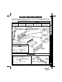
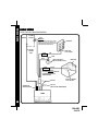
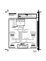
OWNER'S MANU
AL
MANUAL
AND INST
ALLA
TION GUIDE
INSTALLA
ALLATION
LOC
T/F
VOL
MONO
BAND/LOUD
SEL
VOL
EQ
MUTE
PAU
SCN
RPT
SHF
1
2
3
4
MODE
POWER
AS/PS
5
6
ACD-27
AM/FM/MPX RADIO
WITH DETACHABLE FRONT PANEL
COMPACT DISC PLAYER,
CD CHANGER CONTROLS
AND QUARTZ CLOCK
Released 2-28-03.
128-6691
1 of 16
INST
ALL
AT ION INSTRUC
INSTALL
ALLA
INSTRUCTT IONS
INSTALLATION INSTRUCTIONS
This unit is designed for installation in cars, trucks, and vans with an existing radio opening. In many cases, a special
installation kit will be required to mount the radio to the dashboard. These kits are available at electronics supply
stores and car stereo specialist shops. Always check the kit application before purchasing to make sure the kit
works with your vehicle. If you need a kit but cannot find it available, call our toll-free “HELP” line (1-800-645-4994).
UNIVERSAL INSTALLATION PROCEDURE USING MOUNTING SLEEVE
1. Remove the detachable front panel if it is attached to the chassis by pushing the “Release” button. Slide the
mounting sleeve off of the chassis. If it is locked into position, use the removal tools (supplied) to disengage it.
2. Check the dashboard opening size by sliding the mounting sleeve into it. If the opening is not large enough, carefully
cut or file as necessary until the sleeve easily slides into the opening. Do not force the sleeve into the opening
or cause it to bend or bow. Check that there will be sufficient space behind the dashboard for the radio chassis.
3. Locate the series of bend tabs along the top, bottom, and sides of the mounting sleeve. With the sleeve fully inserted
into the dashboard opening, bend as many of the tabs outward as necessary so that the sleeve is firmly secured
to the dashboard.
4. Place the radio in front of the dashboard opening so that the wiring can be brought through the mounting sleeve.
Follow the wiring diagram carefully and make certain all connections of the wiring harness are secure and insulated
with wire nuts or electrical tape to insure proper operation of the unit. After completing the wiring connections,
attach the front panel and turn the unit on to confirm operation (ignition switch must be “on”). If unit does not operate,
re-check all wiring until problem is corrected. Once proper operation is achieved, turn off the ignition switch and
proceed with final mounting of the chassis.
5. Carefully slide the radio into the mounting sleeve making sure it is right-side-up until it is fully seated and the spring
clips lock it into place.
6. Attach one end of the perforated support strap (supplied) to the screw stud on the rear of the chassis using
the hex nut provided. Fasten the other end of the perforated strap to a secure part of the dashboard either above
or below the radio using the screw and hex nut provided. Bend the strap to position it as necessary.
CAUTION: The rear of the radio must be supported with the strap to prevent damage to the dashboard from the
weight of the radio or improper operation due to vibration.
7. Re-attach the front panel to the chassis. Establish a location for the remote input jack (usually the underside of
the dashboard) if it is a feature of the radio. Anchor it in place using two self-tapping screws (M5x6). Do
not over-tighten screws. Test radio operation by referring to the Operating Instructions for the unit.
INSTALLATION USING KITS
1. If your vehicle requires the use of an installation kit to mount this radio, follow the instructions included with the
installation kit to attach the radio to the mounting plate supplied with the kit.
2. Wire and test the radio as described in Step 4 above.
3. Install the radio/mounting plate assembly to the sub-dashboard according to the instructions of the installation kit.
4. Attach the support strap to the radio and dashboard as described in Step 6 above.
5. Replace the dashboard trim panel.
ISO INSTALLATION PROCEDURE
2
This unit has threaded holes in the chassis side panels which may be used with the original factory mounting
brackets of some Toyota, Nissan, Mitsubishi, Isuzu, Hyundai and Honda vehicles to mount the radio to the
dashboard. Please consult with your local car stereo specialist shop for assistance on this type of installation.
1. Remove the existing factory radio from its dashboard or center console mounting. Save all hardware and
brackets as they will be used to mount the new radio.
2. Carefully un-snap the plastic frame from the front of the new radio chassis. Remove and discard the frame.
3. Remove the factory mounting brackets and hardware from the existing radio and attach them to the new radio.
CAUTION: DO NOT EXCEED M5 X 6 MM MAXIMUM SCREW SIZE.
LONGER SCREWS MAY TOUCH AND DAMAGE COMPONENTS INSIDE THE CHASSIS.
4. Wire the new radio to the vehicle as per step 4 of the Installation Instructions.
5. Mount the new radio assembly to the dashboard or center console using the reverse procedure of step 1.
128-6691
2 of 16
DAY
MON. - FRI.
SATURDAY
PACIFIC
5:30AM - 4PM
6AM - 2PM
MOUNTAIN
6:30AM - 5PM
7AM - 3PM
CENTRAL
7:30AM - 6PM
8AM - 4PM
EASTERN
8:30AM - 7PM
9AM - 5PM
UNIVERSAL INSTALLATION USING MOUNTING SLEEVE
NUT (5MM)
PERFORATED STRAP
FASTEN THIS END TO SCREW
STUD ON REAR OF CHASSIS
EXISTING DASH OPENING
FILE EDGES TO FIT IF NECESSARY - DO NOT OVERFILE
NOTE: IF DASH IS SOLID, USE REAR SIDE (WITHOUT THE LIP) OF
MOUNTING SLEEVE AS A TEMPLATE & CUT OPENING
BEND TOP
TABS UPWARD
SCREW
(5MM)
INST
ALL
AT ION INSTRUC
INSTALL
ALLA
INSTRUCTT IONS
TOLL-FREE INST
ALL
AT ION ASSIST
A NCE
INSTALL
ALLA
ASSISTA
The installation and wiring connections for this unit are so simple, we doubt you'll need our help, but, if you
do, we're here to help you. Just call our toll-free telephone assistance line at 1-800-645-4994 during the days
and hours shown (U.S.A. and Canada only).
BEND BOTTOM
TABS DOWNWARD
RADIO
SCREW STUD
NUT (5MM)
MOUNTING SLEEVE
FASTEN THIS END TO SECURE PART OF DASHBOARD. DRILL HOLE IF NECESSARY.
CAUTION:
FOR PROPER OPERATION OF THE CD PLAYER, THE CHASSIS
MUST BE MOUNTED WITHIN 20° OF HORIZONTAL. MAKE
SURE THE UNIT IS MOUNTED WITHIN THIS LIMITATION.
REMOVAL TOOLS
DETACHABLE
FRONT PANEL
20° MAX.
SIDE VIEW
OF
CHASSIS
FRONT PANEL
ISO INSTALLATION
TYPICAL INSTALLATION
REMOVE THE PLASTIC FRAME FROM THE FRONT OF THE
CHASSIS BY CAREFULLY UN-SNAPPING IT.
UN-SNAP AT 2 PLACES
EACH ON TOP AND BOTTOM
PLASTIC FRAME
MAXIMUM
SCREW SIZE
M5 x 6
MAXIMUM
SCREW SIZE
M5 x 6
FACTORY MOUNTING
BRACKETS
3
128-6691
3 of 16
RADIO WIRING
R A DIO WIRING
REFER TO PAGE 5 FOR SPEAKER WIRING
ANTENNA
AUTOMATIC
ANTENNA
BLUE
IMPORTANT
THE BLUE WIRE CAN BE USED TO REMOTELY ACTIVATE AN AUTOMATIC ANTENNA OR AN EXTERNAL AMPLIFIER (SEE
ANTENNA OR AMPLIFIER MANUAL)
EXISTING
ANTENNA
CABLE
0.5 AMP
FUSE
FUSEBLOCK
“RADIO” FUSE
+12V ACCESSORY
RED
SCREW
BLACK
15 AMP
FUSE
METAL PART OF DASH
(DRILL HOLE IF NECESSARY)
CAR BATTERY
YELLOW
IMPORTANT
YELLOW WIRE MUST BE CONNECTED
AS SHOWN OR RADIO WILL NOT
OPERATE PROPERLY
4-PIN PLUGS
POSITIVE (+) TERMINAL
12 VOLT BATTERY
9 PIN PLUG
(SEE PAGE 5 FOR SPEAKER WIRING)
ANTENNA LEAD
ON REAR OF RADIO
RADIO
4
33
128-6691
4 of 16
WARNING!
! THE AMPLIFIERS IN THIS RADIO ARE ONLY DESIGNED FOR USE WITH 4 SPEAKERS.
! NEVER COMBINE (BRIDGE) OUTPUTS FOR USE WITH 2 SPEAKERS.
! NEVER GROUND NEGATIVE SPEAKER LEADS TO CHASSIS GROUND.
! FAILURE TO WIRE EXACTLY AS SHOWN BELOW MAY CAUSE ELECTRICAL DAMAGE TO
THE RADIO.
REFER TO PAGE 4
FOR RADIO WIRING
RCA LINE OUT JACKS
FOR USE WITH OPTIONAL
EXTERNAL AMPLIFIERS
SPE
A K ER WIRING
SPEA
SPE
A K ER WIRING
SPEA
RADIO
RED=RIGHTREAR
WHITE=LEFT REAR
4-PIN PLUGS
9-PIN PLUGS
SEE PAGE 4 FOR
RADIO WIRING
LEFT FRONT SPEAKER
RIGHT FRONT SPEAKER
GRAY w/BLACK STRIPE
WHITE w/BLACK STRIPE
WHITE
GRAY
GREEN
VIOLET
GREEN w/BLACK STRIPE
VIOLET w/BLACK STRIPE
HELP!
1-800-645-4994
LEFT REAR SPEAKER
Monday - Friday
Saturday
8:30am - 7:00pm Eastern
9:00am - 5:00pm Eastern
RIGHT REAR SPEAKER
128-6691
5 of 16
5
OPER
AT ING INSTRUC
OPERA
INSTRUCTT IONS
OPER
AT ING INSTRUC
OPERA
INSTRUCTT IONS
27
24
8
14
15
25
22
10
T/F
LOC
11
16
17
VOL
BAND/LOUD
MONO
2
SEL
VOL
3
4
5
6
7
EQ
MUTE
PAU
SCN
RPT
SHF
1
2
3
4
MODE
POWER
AS/PS
5
6
26
9
28,29
(BEHIND PANEL)
12
18
21
Press this button to turn the unit on or off. If
the unit is off and the ignition switch is on,
the unit will turn on automatically when a disc
is inserted, or when the MODE switch or
BAND switch is pressed.
2 VOLUME / LEVEL CONTROL
To increase the volume level, press the VOL +
button. The volume will increase and the level
will be shown on the display panel from a minimum of VOL 00 to a maximum of VOL 100. To
increase the volume quickly, keep the button
pressed. To decrease the volume level, press
the VOL - button. Keep the button pressed to
decrease the volume quickly. The display will
automatically return to the normal indication 5 seconds after the last volume adjustment or when another function is activated.
These buttons are also used in conjunction
to adjust
with the Audio Select (SEL) button
the bass, treble, balance, and fader levels as
described in , ,
and .
3
456
7
3 AUDIO SELECT (SEL) BUTTON
This button is used to select the audio function (volume, treble, bass, balance, or fade) to
be adjusted using the Volume/Level Controls
. Pressing the SELbutton will select bass
2
19
20
1
13
1 ON/OFF POWER BUTTON
6
23
(BAS on the display), treble (TRB), balance
(BAL), fader (FAD) or volume (VOL). The
display will automatically return to the normal indication 5 seconds after the last adjustment or when another function is activated.
4 BASS CONTROL
To adjust the bass level, first select the Bass
mode by pressing the SEL button
so that
the BAS indication appears on the display
panel. Within 5 seconds of choosing the Bass
to
mode, press the VOL + or VOL - button
adjust the bass response as desired. The
bass level will be shown on the display panel
from a minimum of BAS--10 to a maximum of
BAS 10 (BAS 00 represents flat response).
The display will automatically return to the
normal indication 5 seconds after the last
adjustment or when another function is activated. Adjusting the bass level will automatically return the equalizer setting to the FLAT
mode from its previous setting.
3
2
5 TREBLE CONTROL
To adjust the treble level, first select the Treble
mode by pressing the SEL button
so that
the TRB indication appears on the display
panel. Within 5 seconds of choosing the Treble
mode, press the VOL + or VOL - button
to
3
2
128-6691
6 of 16
6 LEFT/RIGHT BALANCE CONTROL
To adjust the left-right speaker balance, first
select the Balance mode by pressing the SEL
button
so that the BAL indication appears
on the display panel. Within 5 seconds of
choosing the Balance mode, press the
VOL + or VOL - button
to adjust the balance as desired. The balance position will be
shown on the display panel from BAL 10L (full
left) through BAL 10R (full right). When the
volume level between the left and right speakers is equal, BAL L=R will be shown on the
display panel. The display will automatically
return to the normal indication 5 seconds after
the last adjustment or when another function is
activated.
3
2
7 FRONT/REAR FADER CONTROL
To adjust the front-rear speaker balance, first
select the Fader mode by pressing the SEL
so that the FAD indication appears
button
on the display panel. Within 5 seconds of
choosing the Fader mode, press the VOL + or
VOL - button
to adjust the front-rear speaker
balance as desired. The fader position will be
shown on the display panel from FAD 10R (full
rear) through FAD 10F (full front). When the level
between the front and rear speakers is equal,
FAD F=R will be shown on the display panel.
The display will automatically return to the
normal indication 5 seconds after the last
adjustment or when another function is activated.
3
2
8 LOCAL (LOC) OPERATION
This feature is used to select the strength of the
signals at which the radio will stop during
Automatic Seek Tuning. Pressing the button
will select the Local setting (LOCAL will appear
on the display panel for 5 seconds and LOC will
remain in the center of the display) and only
strong (local) stations will be received. Pressing
and holding the button again will select the
Distant setting (Dx will appear on the display
panel for 5 seconds) and the radio will stop at
a wider range of signals, including weaker
(more distant) stations.
9 AUDIO MUTE (MUTE)
This button is used to mute the volume from
the system. By pressing the button, a flashing MUTE indication will appear on the display panel and the volume will be muted.
Pressing the Mute button again, or activating
any other function of the unit will return the volume level to the setting in use before the Mute
function was activated.
OPER
AT ING INSTRUC
OPERA
INSTRUCTT IONS
adjust the treble response as desired. The
treble level will be shown on the display panel
from a minimum of TRB--10 to a maximum of
TRB 10 (TRB 00 represents flat response). The
display will automatically return to the normal indication 5 seconds after the last adjustment or when another function is activated.
Adjusting the treble level will automatically
return the equalizer setting to the FLAT mode
from its previous setting.
bl BAND/LOUDNESS CONTOUR SELECTION
(BAND/LOUD)
During radio operation, each momentary
press of this button will change the radio band.
The indication AM, F1, F2, or F3 will appear on
the display panel according to your selection.
When listening to music at low volume levels,
the loud feature will boost the bass and
treble ranges to compensate for the characteristics of human hearing. Press the
BAND/LOUD button for at least 2 seconds to
activate this feature as indicated by a beep
tone and LOUD ON appearing on the display
panel for about 5 seconds. (LOUD remains on the display.) Pressing the button again for 2 seconds will sound a beep
tone and LOUD OFF will appear on the display for about 5 seconds.
7
128-6691
7 of 16
OPER
AT ING INSTRUC
OPERA
INSTRUCTT IONS
bm MANUAL UP/DOWN TUNING (+
/
-)
AUTOMATIC SEEK TUNING
Each time the +
button is pressed, the
radio will tune higher, seeking the next strong
station and stop. Similarly, each press of the
- button will tune lower and stop at the next
strong station. To manually seek a specific station, press the button of the appropriate direction until the desired frequency is reached.
Pressing either button for longer than 2.0 seconds will cause MANUAL to appear on the display. Now when the Up or Down tuning button
is pressed momentarily, tuning will occur two
frequency steps at a time. If either button is
pressed and held in Manual mode for 2 seconds, the manual Seek Tuning function is
initiated, whereby the radio will tune rapidly in
the appropriate direction and stop on, or close
to, the desired frequency when the button is
released.
If no further tuning is performed after 5 seconds, AUTO will appear momentarily on the
display, and tuning will revert to the original
tuning mode.
bn AUTO-STORE TUNING (AS)
PRE-SET SCAN TUNING (PS)
During radio operation, press this button momentarily to scan the 6 stations in the pre-set
memories of the FM band in use. The unit will
stop at each pre-set station for 10 seconds
before continuing to the next pre-set station
(the frequency on the display panel will flash
during Pre-Set Scan operation). Press the button again momentarily to stop Pre-Set Scan
operation and remain on the selected frequency in that band.
Pressing the button for longer than 2 seconds
will activate the Auto-Store Tuning feature. The
radio will automatically scan the band in use
and enter strong stations into the pre-set
memory positions for that band. If you have
already set the pre-set memories of that band
to your favorite stations, activating the AutoStore Tuning feature will erase those stations
and enter the new strong stations. This feature
is most useful when traveling in a new area
where you are not familiar with the local stations.
bo STATION PRE-SET MEMORIES
To set any of the 6 pre-set memory buttons,
use the following procedure:
1. Turn the radio on and select the desired
band.
2. Select the first station to be pre-set using
the Manual Up/Down or Automatic Seek
.
Tuning Controls
3. Press the pre-set button (1-6) to be set
and continue to hold it in. After approximately 2 seconds, the pre-set number
will appear on the display panel, indicating that the station is now set into that preset memory position. The station can now
be recalled at any time by pressing that
button.
4. Repeat the above procedure for the remaining pre-sets on that band and for the
other 3 bands on the unit.
bm
bp LIQUID CRYSTAL DISPLAY PANEL
FUNCTIONS
The Liquid Crystal Display (LCD) panel displays the frequency, time, and all activated functions, including five bar graphs which provide a
visual representation of the audio signal level.
NOTE: It is a characteristic of LCD panels that,
if subjected to cold temperatures for
an extended period of time, they may take
longer to illuminate than under normal
conditions. In addition, the visibility of
the numbers on the LCD may slightly
decrease. The LCD readout will return to normal when the temperature
increases to a normal range.
8
7
128-6691
8 of 16
With the label surface facing up, gently insert
the disc into the slot until the soft-loading
mechanism engages and disc play begins.
indiS--CDP will appear momentarily; the
cation will become animated, and CDP appears together with the track number and
elapsed time.
CAUTION: This unit is designed for play
of standard 5" (12cm) Compact
Discs ONLY. Do not attempt to use
3" (8cm) CD-Singles in this unit,
either with or without an adaptor,
as damage to the player and/or
disc can occur. Such damage will
not be covered by the Warranty
on this product.
br TRACK SELECT
These buttons are used to quickly select the beginning of a particular track. With each momentary press of the Forward Track Select button
), the next higher track number will be
(+
selected as shown on the display panel. Similarly, with each momentary press of the Backward Track Select button (
- ), the next lower
track number will be selected.
bs CUE/REVIEW FUNCTIONS
High-speed audible search to any section of
the disc can be made by the Cue and Review
functions. Press and hold the Cue button
) to advance rapidly in the forward direc(+
-) to advance raption or the Review button (
idly in the backward direction. During either
function, the elapsed time within each track will
automatically be shown on the display panel.
bt DISC PAUSE (PAU) SELECT
The Pause function is used to freeze disc play
when the CD player is in use.S--PAUSE will
appear on the display. Press this button again
to resume disc play; the S--PAUSE indication
will disappear.
bu REPEAT PLAY SELECTOR (RPT)
During disc play, press this button to repeat
the play of the selected track (S--RPT will
appear on the display panel). Play of the track
will continue to repeat until the button is
pressed again and the S--RPT indication disappears from the display panel. Repeat Play
mode will also be cancelled by activating the
or Track Scan
functions.
Shuffle Play
cl
cm
cl SHUFFLE PLAY SELECTOR (SHF)
During disc play, press this button to play the
tracks on the disc in a random shuffled order
(S--SHF) will appear on the display panel). In
Shuffle Play mode, pressing the Forward
) or Backward Track SeTrack Select (+
lect (
-) will also select tracks in a random
order instead of the normal progression. Additional presses will select tracks in random
order. The Shuffle Play mode can be cancelled by pressing the button again (S--SHF)
indication will disappear from the display
or
panel) or by activating the Repeat Play
Track Scan
functions.
OPER
AT ING INSTRUC
OPERA
INSTRUCTT IONS
bq DISC SLOT
bu
cm
cm TRACK SCAN (SCN)
During disc play, press this button to play the
first 10 seconds of each track on the disc
(S--SCN will appear on the display panel with
the track number). When a desired track is
reached, press the Scan button again to cancel the function and play of the selected
track will continue. Track Scan mode will
also be cancelled by activating the Repeat
or Shuffle Play
functions.
Play
bu
cl
cn DISC EJECT (
)
When this button is pressed, disc play is
stopped, the disc is ejected and the unit will
change to radio operation. If the disc is not removed from the unit within 15 seconds, the
disc will be reloaded (CDP will reappear).
9
128-6691
9 of 16
OPER
AT ING INSTRUC
OPERA
INSTRUCTT IONS
co TIME/FREQUENCY SELECTOR (T/F)
This unit can display the clock time, radio frequency or CD player functions on the display
panel. Pressing the Time/Frequency Selector button when the radio frequency or CD
player track indication is shown, will change
the display to show the time. The time display
will automatically return to the radio frequency
or CD player function indication after 5 seconds.
cp
FM MONO/STEREO SELECTOR (MONO)
During FM radio operation, this button is used
to select mono or stereo reception of the broadcast signal. Under normal reception conditions,
the unit should be left in the stereo mode, as
indicated by ST on the display panel when listening to an FM stereo signal. If the stereo signal is too weak for comfortable listening, press
the button to switch to mono reception (the ST
indication will disappear and MONO appears
on the display panel). To return to the stereo
reception mode, press the button again so that
the ST indication returns.
cq EQUALIZER SELECTOR (EQ)
The EQ button applies preset sound effects to
the unit’s audio output signal. The EQ button,
when pressed, will activate one of the following
operating modes: CLASSICS, POP M, ROCK M,
DSP OFF, or FLAT. When the EQ function is
active, as displayed (EQ ----CLAS, POP, ROCK)
on the panel, the bass and treble levels can still
be changed to accommodate the listener’s ear.
However, when the levels are changed, the
equalizer function is disabled. When the EQ
function is not active, the unit returns to the userset bass and treble levels. The FLAT selection
indicates no equalizer enhancement of the program, thereby removing the preset sound effects, unless otherwise desired. DSP OFF
disables display of the equalizer setting.
cr MODE SELECTOR (MODE)
10
This button is used to select the radio, or the
playback mode for the CD player. Each press
of the button will select a different mode
as indicated on the display panel.
During CD player operation, this button may
be used to change to radio without ejecting
the disc (the CDP indication will remain on
the display panel to show that a disc is still
loaded in the unit). Press the button again to
return to CD player mode.
cs FRONT PANEL RELEASE BUTTON
This button is used to release the mechanism that holds the front panel to the chassis.
To detach the front panel, press the button so
that the left side of the panel is released.
Grasp the released side and pull it off of the
chassis.
To re-attach the panel, position the right side
of the panel in place first and then press in the
left side of the panel until the mechanism
locks it into place.
ct THEFT-DETERRENT LED
The theft-deterrent Light Emitting Diode (LED)
is located behind the front panel and is accessible when the front panel is removed.
The flashing light serves as a visual warning
to the would-be thief that the unit has been
disabled by removal of the front panel.
cu RESET BUTTON
A RESET button is located on the front of the
chassis (front panel must be removed to
access the button). The RESET circuitry is
provided to protect the microprocessor circuitry and should only be activated under the
following circumstances as it will erase the
time and pre-set memories:
1. Upon initial installation after all wiring is
completed.
2. If there is a malfunction of any of the
switches on the unit, pressing the RESET
button may clear the system and return to
normal operation.
128-6691
10 of 16
1. Make sure the front panel is right-sideup when attaching it to the chass is
as it cannot be attached when up-side
down.
2. Do not press very hard on the front panel
when attaching it to the chassis. No
more than light to moderate pressure
should be needed.
3. When attaching the front panel, make
sure the right side is correctly engaged
before pressing the left side to lock it
into position.
4. When taking the front panel with you,
please use the supplied carrying case
to protect the panel from dirt and damage. Make sure there is no dust or dirt
on the electrical terminals on the back
of the panel as this could cause intermittent operation or other malfunctions.
DETACHING THE FRONT PANEL
Release Button
ATTACHING THE FRONT PANEL
Engage right
side first
SET
SETTT ING THE CLOCK
1. Turn the vehicle ignition and radio on (radio frequency or disc track number will be shown
on the display panel).
2. Momentarily press the Time/Frequency (T/F) button co to display the time of day. Then
press and hold the T/F button until the time display flashes.
) to adjust the hours and
3. While the display is flashing, press the Up Tuning button (+
-) to adjust the minutes to the
the A or P indication, and the Down Tuning button (
correct time.
NOTES
FRONT
REMOTE
SETTT ING THE CLOCK
NO
TES ON FR
ONT PPA
A NEL / REMO
TE INPUT JACK / SET
NOTES ON USE OF FRONT PANEL
4. When the correct time is shown on the display panel, press and release the T/F button
(or wait 5 seconds) for the display to return to the normal indication.
11
128-6691
11 of 16
SPECIFICA
SPECIFICATT IONS
SPECIFICATIONS
Size:
7" W x 2" H x 6-5/16" D
178 mm x 50 mm x 163 mm
Operating Voltage:
12 volts DC, negative ground
Output Power:
160 watts maximum
(40 watts x 4 channels)
Output Wiring:
Floating-ground type designed for 4 speaker use.
Front and rear channels CANNOT be combined (bridged)
for use with 2 speakers.
RCA low-level outputs (rear channels).
Output Impedance:
Compatible with 4 ohm speakers.
Low-Level Output:
0.8 volt (800 mv, 600mV Limit)
Tuning Range:
AM: 530 - 1,710 kHz. (10 kHz. step)
FM: 87.5 - 107.9 MHz. (200 kHz. step)
Sensitivity:
4.0 uV
FM Stereo Separation:
25 dB
CD Frequency Response: 20 - 20,000 Hz. +0 / -3 dB
CD Signal/Noise Ratio:
55 dB
CD Channel Separation: 1kHz Limit: 50 dB, 10kHz Limit: 40 dB
CD Distortion:
0.2%
*Specifications are subject to change without notice.
CD-R AND CD-RW PLAYBACK CAPABILITY
This model can play most CD-R and CD-RW media that contains audio programs.
Playback of both CD-R and CD-RW depends on the conditions of the recording equipment
and the CD-R or CD-RW disc quality. In some cases, a CD-R or CD-RW disc cannot be played
on this unit.
12
128-6691
12 of 16
If a problem should develop while operating the CD player, an error code (ER-1, ER-2, ER-3,
etc.) may appear on the display panel. This can indicate a number of problems with the unit,
including a mechanical error or an error in the microprocessor control of the player. If an error
code should appear, try ejecting and re-loading the disc into the player. While the disc is out of
the unit, make sure it is clean, undamaged, and loaded correctly (label surface up). You may
also try activating the RESET button
on the unit, but this will also erase the time and pre-set
memories.
If the suggested measures do not solve the problem, contact an approved warranty station near
you for further assistance.
cu
13
PLA
AND
CHA
ERROR
CD PL
AYER A
ND CD CH
A NGER ERR
OR CODES
CD PL
AYER ERR
OR CODES
PLA
ERROR
13
128-6691
13 of 16
CA
RE A
ND MA
INTENA
NCE
CARE
AND
MAINTENA
INTENANCE
CA
RE A
ND MA
INTENA
NCE
CARE
AND
MAINTENA
INTENANCE
CARE AND MAINTENANCE
The radio section of your new sound system does not require any maintenance. We
recommend that you keep this manual for reference on the many features found in this unit as
well as how to set the clock.
The compact disc player section also requires no routine maintenance, but proper
understanding of its use and handling will help you obtain maximum enjoyment of its
capabilities. The following points should be observed:
! When cleaning the interior of the vehicle, do not get water or cleaning fluids on the unit.
! The CD player is a precision instrument and will not operate properly in extreme heat or cold.
In case of such conditions, wait until the interior temperature of the vehicle reaches a normal
temperature before using the player.
! If the temperature inside the player gets too hot, a protective circuit will automatically stop
play of the disc. In this case, allow the unit to cool off before operating the player again.
! Never insert anything other than a 5" (12 cm) compact disc into the player as the mechanism
can be damaged by foreign objects.
! Do not attempt to use 3" (8 cm) CD-Single discs in this unit, either with or without an adaptor,
as damage to the player and/or disc may occur. Such damage will not be covered by the
Warranty on this product.
! When not using the disc player, always remove the compact disc. Do not leave an ejected
disc sitting in the disc slot as this can expose it to sunlight and other causes of damage.
! Do not attempt to open the unit chassis. There are no user serviceable parts or adjustments inside.
! When the vehicle warms up during cold weather or under damp conditions, moisture may
condense on the lens of the disc player. Should this occur, the player will not operate
properly until the moisture has evaporated.
! The unit is designed with a vibration dampening CD mechanism to minimize interruption of
disc play due to normal vibration in a moving vehicle. When driving on very rough roads,
however, occasional sound skips may occur. This will not scratch or damage the disc and
normal play will resume when the rough conditions cease.
HANDLING COMPACT DISCS
Dirt, dust, scratches, and warpage can cause skips in the playback and deterioration of sound
quality. Please follow these guidelines to take care of your compact discs:
! Use only compact discs with the mark
.
! Fingerprints, dust, and dirt should be carefully wiped off the disc’s playing surface (shiny side)
with a soft cloth. Wipe in a straight motion from the inside to the outside of the disc.
! Never use chemicals such as record sprays, household cleaners or thinner to clean compact
discs. Such chemicals can irreparably damage the disc’s surface.
! Discs should be kept in their storage cases when not in use.
! Do not expose discs to direct sunlight, high temperatures or high humidity for extended periods.
14
! Do not stick paper, tape, or labels on the disc surfaces nor write on them with any type of marker.
128-6691
14 of 16
AUDIOVOX ELECTRONICS CORPORATION (the Company) warrants to the original
retail purchaser of this product that should this product or any part thereof, under
normal use and conditions, be proven defective in material or workmanship within 12
months from the date of original purchase, such defect(s) will be repaired or replaced
with new or reconditioned product (at the Company's option) without charge for parts
and repair labor.
To obtain repair or replacement within the terms of this Warranty, the product is to be
delivered with proof of warranty coverage (e.g. dated bill of sale), specification of defect(s),
transportation prepaid, to the warranty center at the address shown below.
This Warranty does not extend to the elimination of car static or motor noise, to correction
of antenna problems, to costs incurred for installation, removal, or reinstallation of the
product, or damage to tapes, compact discs, speakers, accessories, or vehicle electrical
systems.
W A RR A NT Y
12 MONTH LIMI
TED W
A RR
A NT
Y
LIMITED
WA
RRA
NTY
This Warranty does not apply to any product or part thereof which, in the opinion of the
Company, has suffered or been damaged through alteration, improper installation,
mishandling, misuse, neglect, accident, or by removal or defacement of the factory serial
number/bar code label(s). THE EXTENT OF THE COMPANY'S LIABILITY UNDER
THIS WARRANTY IS LIMITED TO THE REPAIR OR REPLACEMENT PROVIDED
ABOVE AND, IN NO EVENT, SHALL THE COMPANY'S LIABILITY EXCEED THE
PURCHASE PRICE PAID BY PURCHASER FOR THE PRODUCT.
This Warranty is in lieu of all other express warranties or liabilities. ANY IMPLIED
WARRANTIES, INCLUDING ANY IMPLIED WARRANTY OF MERCHANTABILITY,
SHALL BE LIMITED TO THE DURATION OF THIS WRITTEN WARRANTY. ANY
ACTION FOR BREACH OF ANY WARRANTY HEREUNDER INCLUDING ANY IMPLIED
WARRANTY OF MERCHANTABILITY MUST BE BROUGHT WITHIN A PERIOD OF 30
MONTHS FROM DATE OF ORIGINAL PURCHASE. IN NO CASE SHALL THE
COMPANY BE LIABLE FOR ANY CONSEQUENTIAL OR INCIDENTAL DAMAGES
FOR BREACH OF THIS OR ANY OTHER WARRANTY, EXPRESS OR IMPLIED,
WHATSOEVER. No person or representative is authorized to assume for the Company
any liability other than expressed herein in connection with the sale of this product.
Some states do not allow limitations on how long an implied warranty lasts or the
exclusion or limitation of incidental or consequential damage so the above limitations or
exclusions may not apply to you. This Warranty gives you specific legal rights and you
may also have other rights which vary from state to state.
U.S.A.: AUDIOVOX ELECTRONICS CORPORATION, 150 MARCUS BLVD., HAUPPAUGE, NEW YORK 11788 • 1-800-645-4994
CANADA: CALL 1-800-645-4994 FOR LOCATION OF WARRANTY STATION SERVING YOUR AREA
Form No. 128-4270A
15
128-6691
15 of 16
© 2003 Audiovox Electronics Corp., Hauppauge, NY 11788
Printed in China
128-6691
128-6691
16 of 16